

Page 1

1 UBS-VI-V08E
U
U
B
B
S
S
S
S
e
errii
e
ess
U
U
B
B
S
S
S
S
e
errii
e
ess
B
Brr
u
uss
h
hll
e
essss
D
D
C
C
M
M
o
ott
o
orr
D
Drriivv
e
err
U
Uss
e
err
’
’
ss M
M
a
a
n
n
u
u
a
all
Page 2

2 UBS-VI-V08E
Precautions
Precautions for using
1.Thank you for purchasing TROY products. Please read this user’s manual thoroughly before
installing and operating the driver, and always keep the manual where it is readily available.
2. The products described in this manual has been designed and manufactured for use in
industrial machinery, and must not be used for any other purpose. We are not responsible for
any damage caused through failure to observe this warning.
3.Check that the motor, driver and any accessories are all present. If an accessory is missing or
damaged, contact the nearest our branches.
4.Never disassemble the motor and driver. Damage or performance impairment may result.
Disassembly voids all warranties.
Precautions for maintenance
Check the ambient environments, clean the system equipment to remove dust and tighten the
screws periodically. Also pay attention to the followings.
1. Contact us when repairs become necessary.
2. Since the temperature of the frame of the driver can rise high, be careful when conducting
maintenance work or inspection work.
Precautions for warranty period
Within the period of one year after delivery of the system equipment, when failures occurring
from design error or fabrication error attributable to the manufacture side occur, we will be
repairing the failure free of charge within the reparable range or will replace with substitute.
(We cannot hold ourselves responsible for breakage and accidents occurring from your use
beyond the specified range described in this document.)
Precautions for disposal
When disposing of the driver and the motor, treat them as ordinary industrial waste.
Page 3

3 UBS-VI-V08E
1
Contents
1.UDB system………………………………………………………2
2.Specification……………………………………………………..3
2.1Specs…………………………………………………………….3
2.2Specs of motor/driver………………………………………...3
3.Verifying the combination……………………………………..4
3.1Verifying the content of package……………………………4
3.2Verifying the product name and spec……………………...4
4.Function of driver……………………………………………….5
5.Installation………………………………………………………..7
5.1Wiring ……………………………………………………………7
5.2Operation………………………………………………………..7
6.Installation of driver…………………………………………….10
6.1Installation………………………………………………………10
6.2Installation condition………………………………………….11
7.Dimensions……………………………………………………….12
Page 4
2 UBS-VI-V08E
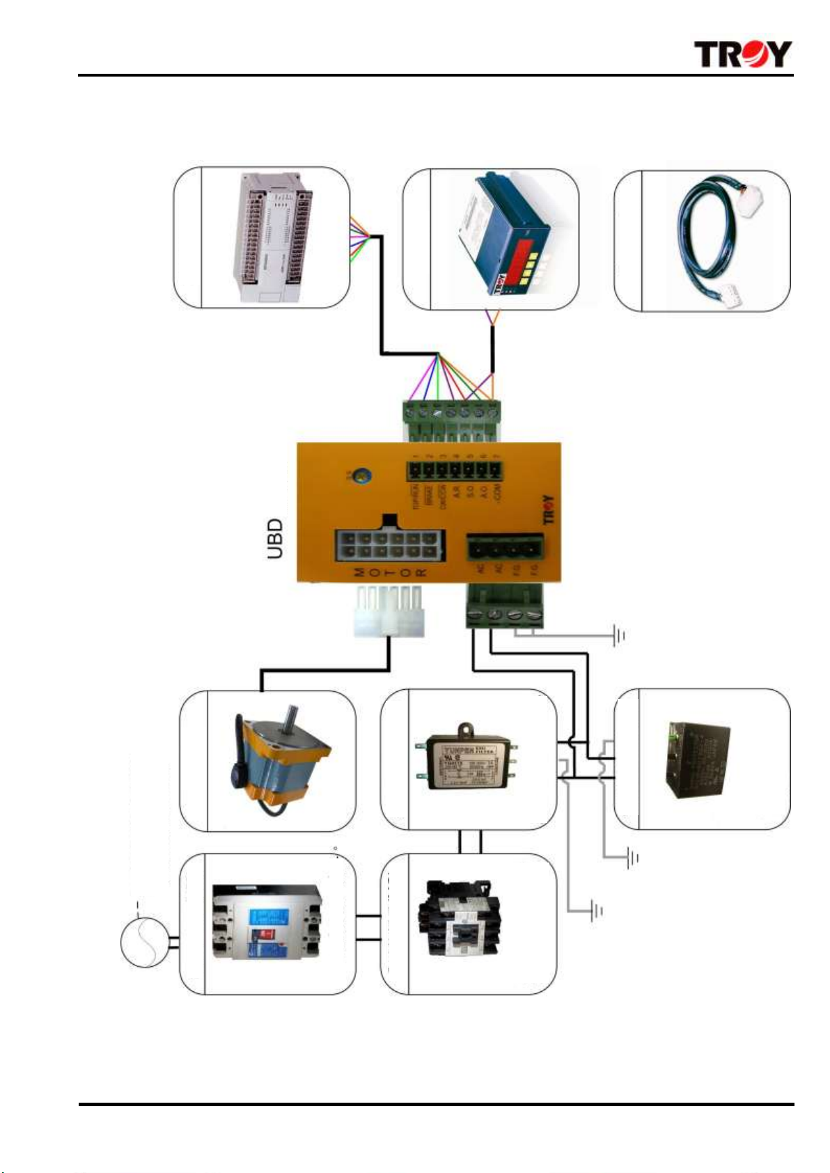
System
Programmable
Controller
Speed Indicator
Accessories
Extension Cable
Power 110V or 220V
(Depending on driver model)
Motor
Noise Filter (NSF)
Surger Protector
(SPD)
Prevent the damage
from surge or lightening
strike
1.UBD System
Page 5
3 UBS-VI-V08E
Motor output
20W
40W
60W
90W
Round shaft
6B020S-□N
6B040S-□N
9B060S-□N
9B090S-□N
Pinion shaft
6B020P-□N
6B040P-□N
9B060P-□N
9B090P-□N
Input
Power
-Type 1
AC110~115
V 15%
50 / 60 Hz
Max
Current
2.4A
2.4A
2.5A
2.9A
Rated
Current
0.59A
0.99A
1.48A
1.93A
-Type 2
AC220~230
V15%
50 / 60 Hz
Max
Current
1.7A
1.7A
1.7A
1.7A
Max
Current
0.33A
0.56A
0.82A
1.05A
Starting torque (Kgcm/Nm)
Rated Torque (Kgcm/Nm)
1.5 / 0.15
1.0 / 0.10
2.5 / 0.25
2.0 / 0.20
4.5 / 0.45
3.0 / 0.30
6.5 / 0.65
5.0 / 0.50
Permissible load inertia (GD2)
14.01Kgcm2
23.23Kgcm2
39.42Kgcm2
54.23Kgcm2
Speed regulation
250~2000RPM(All ranges output by rated torque)
Speed
variation
To load
-1%(At 2000 rpm within no-load ~rated load)
To voltage
±1% (Power voltage variation: -1±15%. At 2000 rpm with no-load).
To temp.
±2% (0~40℃ At 2000 rpm with no-load)
Speed control
●Controlled by the knob on the front panel
Signal input
●Photocoupler input interface.
●Start/Stop input. Brake input. CW/CCW input. Alarm release input
Signal output
●Open collector output
●SPEED OUT ALARM OUT
Functions
●Controlling the motor run and stop via 「RUN/STOP」
●Speed range 250~2000RPM, motor outputs by FLAT TORQUE
●It has the instantaneous brake stop,CW/CCW,natural stop,slow start/slow
down
●When brake stop activated it has electrical holding torque function
●The protection function activated, motor will stop and the 「ALARM」red
light lit up during motor over load/over speed/over heat/driver low
voltage/driver over voltage/motor cable broken
Item
Driver
Motor
Insulating resistance
When tested with DC500V high
resistance meter, the resistance
between power, F.G ground, and I/O
contact terminal is over 100MΩ.
When tested with DC500V
high resistance meter, the
resistance between wires and
motor case is over 100MΩ.
Insulating voltage resistance
No abnormal symptoms when
supplying 1.8KV/60Hz voltage
between the power and the F.G
ground connection terminal and
3KV/60Hz voltage between the
power and I/O connection terminal
for one minute.
No abnormal symptoms when
supplying 1.8KV/60Hz voltage
continued 1 sec.
Operating
environmental
conditions
Temperature
0~40℃
0~50℃
Humidity
Within 85%
Atmosphere
No corrosive gases,dust and flammable gas
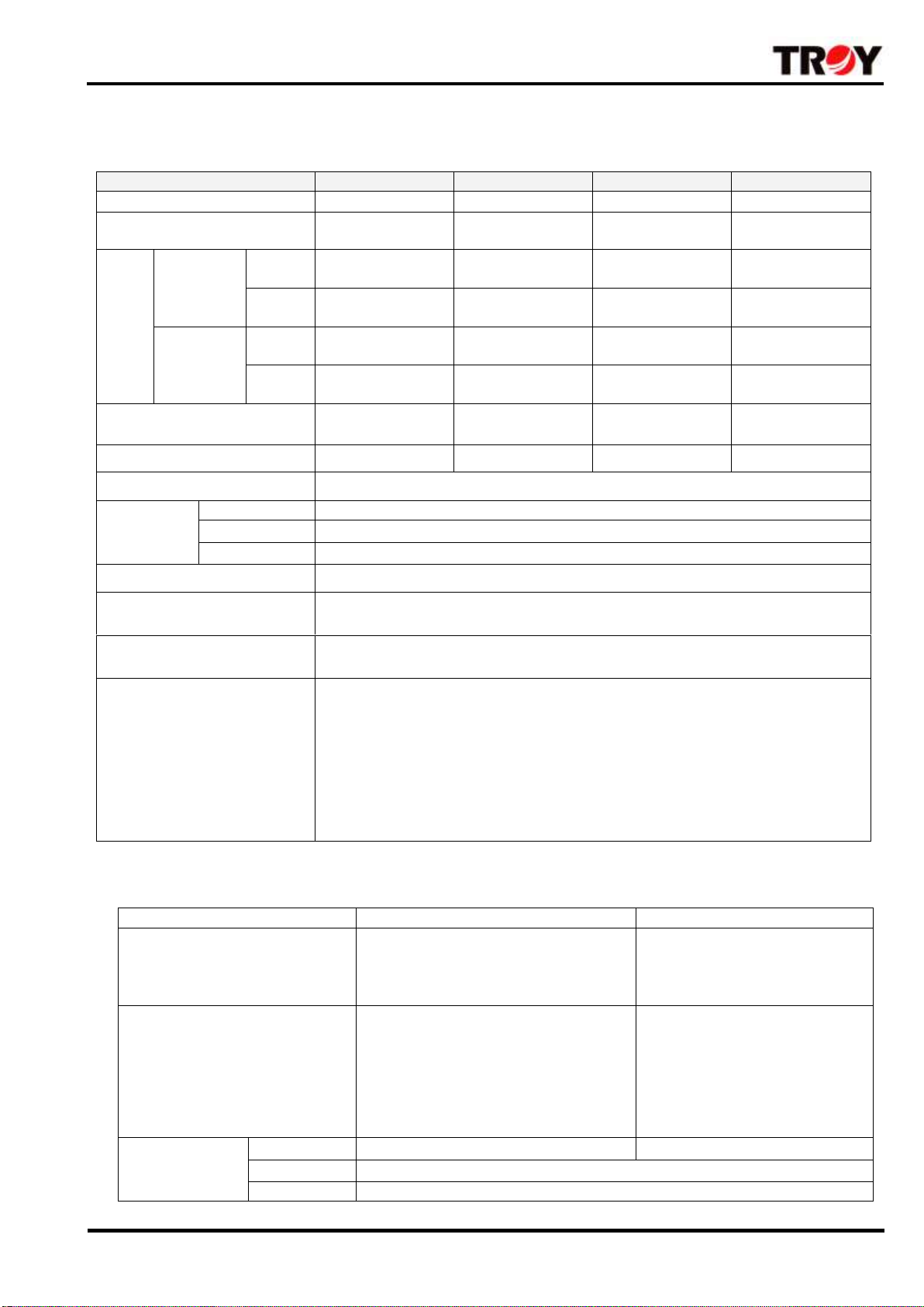
2 Specification
2.1Specs
※Please fill the power in the box-□,”1” indicates AC110V-115V±15%.’’-2’’ indicates AC220V-230V±15%.
2.2 Motor/Controller specs
Page 6

4 UBS-VI-V08E
Item
Quantity
Driver
1
Connector (4 pins)
1
User’s manual
1
Motor
1
Power
Voltage spec
Name of motor
Name of driver
20W
AC110V~115V
6B020S-1N
UBD020-1
AC220V~230V
6B020S-2N
UBD020-2
40W
AC110V~115V
6B040S-1N
UBD040-1
AC220V~230V
6B040S-2N
UBD040-2
60W
AC110~115V
9B060S-1N
UBD060-1
AC220~230V
9B060S-2N
UBD060-2
90W
AC110V~115V
9B090S-1N
UBD090-1
AC220V~230V
9B090S-2N
UBD090-2
Power
Voltage spec
Name of motor
Name of driver
Name of
gearhead
20W
AC110V~115V
6B020P-1N
UBD020-1
6D□
AC220V~230V
6B020P-2N
UBD020-2
40W
AC110V~115V
6B040P-1N
UBD040-1
6D□
AC220V~230V
6B040P-2N
UBD040-2
60W
AC110~115V
9B060P-1N
UBD060-1
9D□
AC220~230V
9B060P-2N
UBD060-2
90W
AC110V~115V
9B090P-1N
UBD090-1
9D□
AC220V~230V
9B090P-2N
UBD090-2
3Verifying the combination when purchased
Upon opening the package, verify that the items listed below are included then install, wring and
operating. If there is any problem please contact our branch.
3.1Verifying the content of package
Round type/Pinion type ※Note:The pinion type has to attached with「GEARHEAD」then it can install
3.2Verifying the product number code
●If you purchased is the 「Round type」please check the combination as below:
●If you purchased is the 「Pinion type」please check the combination as below:
※Note: If you purchased is the 「Pinion type」please select the 「GEARHEAD」to attached with
Page 7

5 UBS-VI-V08E
AC
F.G.
F.G.
AC
R
O
T
O
M
7
COM
-
STOP/RUN
BRAKE
CW/CCW
A.R.
S.O.
A.O.
4
5
6
2
3
1
馬達
連接座
AC電源輸入
連接座
後面板
緩慢起動/停止時間設定器
輸入/輸出信號
連接座
RUN
STOP
UNIT DC BRUSHLESS MOTOR DRIVER
0
10
20
30
40
50
60
70
80
90
100
ALARM
POWER
速度設定
刻度
異常燈號
(紅色)
速度設定
旋鈕
電源燈
(綠色)
運轉/停止
開關
前面板
Scale of speed
setting
ALARM LED
(Red)
Front panel
RUN/STOP
switch
POWER LED
(Green)
External speed
potentiometer
Back side of panel
Input/Output signal
connector
Acceleration/Deceleration
time potentiometer
Motor
connector
AC power input
connector
4.Names and functions of driver
Page 8

6 UBS-VI-V08E
Item
Functions
Front panel
External speed
potentiometer
Regulating the motor speed「Clockwise rotation」from slow to fast
Speed setting scale
0~100 total 10 scales
Scales-Speed contrast chart please refer to the Page 8
Power LED (Green)
When AC power is on, the 「POWER」green light on the front panel will lit up
ALARM LED (Red)
The protection function activated, motor will stop and the 「ALARM」red light lit up
during motor over load/ driver low voltage/ driver over voltage
RUN/STOP Switch
The motor runs or stops which controlled by switch
Switching to the 「RUN」side→motor starts to run
Switching to the 「STOP」side→motor comes to a natural stop
Back side of panel
Motor connector
Please insert the motor cable
AC power input
connector
Please input the AC power voltage according to the specs of driver
「AC」contact:Please connect power line N and L
「FG」contact:Please contact to frame ground of the system
「NC」contact:Not used
Note:The mark of driver voltage specs
「-1」indicates→Single phase AC110~115V±15% 50/60Hz
「-2」indicates→Single phase AC220~230V±15% 50/60Hz
Acceleration/Deceleration
time potentiometer
SS(Slow-start)Acceleration time max 8 sec( 0~2000RPM within no load)
SD(Slow-down)Deceleration time max7 sec( 2000RPM~0RPM within no load)
Input/Output signal
connector
No.
Terminal
name
Name of functions
Functions
1
STOP/RUN
STOP/RUN
Input signal level「L」→ Start
「H」→Stop ※2
2
BRAKE
Brake stop
Input signal level「L」→
Brake stop 「H」→Stop
normally
3
CW/CCW
Clockwise rotation
input/Counterclockwise
rotation input
Input signal level「L」→
Counterclockwise rotation
「H」→Clockwise rotation
4
A.R.
ALARM release
Alarm Reset, input
「Negative trigger signal」→
ALARM release
5
S.O.
Speed output signal
Used when monitoring the
rate of rotation, pulse
signals output 12Pulse/
rotation
6
A.O.
ALARM output signal
The signal is output when
motoroverload/overspeed/
overheat/ driver
overvoltage/driver low
voltage/motor cable broken.
At the same time motor will
stop normally
7
-COM
Output signal power GND
Ground terminal for
input/output signals and
external DC power GND
※1.Acceleration/Deceleration time will be different from the load type (Ex:Inertia,friction)
※2.「L」means contact connected with 「-COM」;「H」means no connect (About the details please refer
to the wiring)
Page 9

7 UBS-VI-V08E
BRAKE
3
5
4
2
1
異常警示信號輸出(動作時L準位輸出)
速度脈波信號輸出(12pulse/回轉)
2k * 2pcs
DC +24V
ON時--剎車停止 / OFF--自然停止
觸發ON時--解除異常狀態
ON時--逆轉 / OFF時--正轉
ON時--啟動 / OFF時--停止
SW1
馬達
減速機
F.G.
F.G.
AC
AC
R
O
O
T
M
-
6
A.O.
COM
7
CW/CCW
STOP/RUN
S.O.
A.R.
控制器面板側
輸入AC電源
L線
N線
馬達電纜線連接器請確實插入控制
器連接座,完全插入時,連接器上
的卡榫會發出輕微的喀答聲
馬達電纜線
Gearhead
Motor
Be sure the motor connector is
fully inserted to the driver
connector
Motor cable
AC power input
A
B
L line
N line
Driver side
C
D
E
F
0
10
20
30
40
50
60
70
80
90
100
UNIT DC BRUSHLESS MOTOR DRIVER
RUN
POWER
STOP
ALARM
1.Turn the AC power SW-ON then
the LED”POWER” of the front
panel will lit up
2. The front side of pane
「RUN/STOP Switch」and back
side「RUN/STOP Contact」must be
set on「RUN」then the motor can
run.
3.Turning the knob「Speed
potentiometer」to CW direction and
the motor speed will increase.
4.Motor stop running「STOP」:
Please switch the button『RUN/STOP』 of
the front panel to the 「STOP」side or
setting to the 「STOP」contact of the back
panel at the moment the motor speed will be
slow down by inertia
Motor
5.Installation
5.1Wiring
A:Speed signal output (12 pulses are output for each rotation)
B:Alarm signal output (It is activated when L level output)
C:ON--Start/OFF--Stop
D:ON--Brake stop/OFF--Stop normally
E:ON—Counterclockwise/OFF--clockwise
F:When triggered ON--Alarm release
※Note: Note: The front side of panel「RUN/STOP Switch」and back side 「RUN/STOP Contact」
must be set on 「RUN」then the motor runs. But there is one of them which set on「STOP」
then motor stops.
5.2 Operation mode
●Operation steps
Page 10

8 UBS-VI-V08E
Type of protection
function
Action
Motor over load
●Activated when a load exceeding the rated torque is applied to the motor
for 7 sec
Over speed
●When motor speed over 3000RPM
Over heat
●Activated when the driver’s ambient temperature exceeds 80℃
Over voltage
●When the motor is driving an inertial load exceeding the permissible
inertial load,or the load do the operation vertically
Low voltage
●When motor running, the AC power input to the driver AC110V or AC220V
which is lower around 20%
Motor cable
broken
●When motor cable was broken
Pay attention to the following details when operated
1.Do not using「Power SW」to control the motor RUN/STOP directly. Because the power turns on
and the motor starts to run at the same time. It will has surge current and driver will damaged
easily.
2.The switch「RUN/STOP」is not a power ON/OFF switch of driver. When the motor is to be
stopped for a long time, please turn the driver 「Power SW」-OFF, push the switch 「RUN/STOP」
to the 「STOP」side and regulated the 「Speed potentiometer knob」counterclockwise to the
scale「0」
3.Before starting the motor, regulated the「Speed potentiometer knob」counterclockwise to the
scale「0」then push the switch「RUN/STOP」to the 「RUN」side. And regulated the 「Speed
potentiometer knob」clockwise to make the speed increasing to the demanded rotation. Please
do not start the motor under the high speed it will has load inertia overshoot and cause the motor
fault.
●Clockwise rotation/Counterclockwise rotation
Note:
When change the direction of rotation「CW/CCW」,please push the switch「RUN/STOP」to the
「STOP」side. Motor can not be reversed instantaneously it will cause the motor fault and wait
the motor comes to a complete stop before switching
●Protection function
The protection function activated, motor will stop and the 「ALARM」red light LED of the front
panel will light up during motor over load/over speed/over heat/over voltage/ low voltage/motor
broken
Note:If there is any exceptional conditions during motor running, please turn the driver’s 「POWER SW 」
OFF,then do the wiring, check the load and power voltage. When the expectional conditions eliminated and
repeat the above-mentioned steps. At this time 「ALARM」light will go out.
Page 11

9 UBS-VI-V08E
Model of extension cable
Length(m)
CB-010
1
CB-020
2
CB-030
3
CB-050
5
CB-100
10
延長電纜線
Extension cable
速度設定器刻度 - 轉速 變化曲線
0
200
400
600
800
1000
1200
1400
1600
1800
2000
2200
0 1 1.5 2.0 2.6 3.5 5.1 6.1 7.5 8.5 9.9 11.3 12.9 14.2 15.5 16.5 17.4 18.5 19.2 19.5 20
0 5 10 15 20 25 30 35 40 45 50 55 60 65 70 75 80 85 90 95 100
速度設定器刻度
轉速
(RPM)
電阻值
(k
Ω
)
Resistance
(KΩ)
Speed potentiometer graduation-Speed(RPM)
After electrify the 「ALARM」light lit up, please contact to our local seller.
「ALARM」release:(1)「A.R.」input contact keep at the「L」condition 10ms then back to the「H」
condition.
(2)Please turn the「POWER SW」OFF more than 5SEC then input the power
●Connecting the motor
The motor is connected to the driver using the connectors provided.Be sure the motor connector
is fully inserted to the driver connector. Please turn the 「POWER SW」OFF while connecting
which avoid the improper connection to cause the driver damaged.
The cable can be extended to a maximum of 10m using an extension cable (Sold
separately).Please choose the suitable extension cable while ordering.
The total length from motor to driver=Motor lead length 45cm+Extension cable length
※Actual cable length = Required length + 10cm
●Connecting the AC Power
The CE and UL certified terminal board shall be used for the power input. When connecting the
driver, fix the power supply wire at the terminal (4-pin accessory) and then insert the terminal into
the power terminal jack on the driver. Use AWG18 power source cable (in profile over 0.75mm2).
The driver power ground (FG) terminal should be connected with Class 3 grounding. Use as
short grounding wires as possible (The ground impedance should be less than 100Ω).
Page 12

10 UBS-VI-V08E
請預留控制器與左右裝置間平
行的間距,作為通風散熱之用
請預留與機殼的間隔空間
,作為空氣流通散熱之用
控制器安裝的機殼
安裝固定板加工圖
採用M4螺絲2顆
安裝固定板
3
90
81
53
26.5
50mm
50mm
M3(4)
M3(4)
25mm
Driver case
Leave sufficient space
for air to pass between the
case
Mounting plate
M4 Screws X2
Leave sufficient space
for air to pass between the driver
Note: When mounting the driver must
be sure to the driver ambient
temperature is not exceeds 40℃ or
cool the driver with fan
6.Driver installation
6.1 Driver installation
Page 13

11 UBS-VI-V08E
以上
6.2Installation condition
●Install and use the driver in the environment described as the following:
※Indoor (without direct sun light exposure) or the place that is well ventilated and easy for
heat
radiation. Don’t not expose to the sunlight directly.
※Ambient temperature:
Controller0℃~+40℃ (Avoid freezing).
Motor 0℃~+50℃ (Avoid freezing)
※Ambient humidity: Below 85% (Avoid condensation).
※The place that will not be affected by water, oil, corrosive and flammable gas or dust.
※The place that will not affected by continuous vibration.
●When the driver is installed in an enclosed place or a place where a heating source exists
nearby, please watch out for the temperature rise of the driver. It is recommended to use
a fan for forced cooling and maintaining the temperature of the driver at below 400C so
as to avoid excessive temperature inside the driver and activation of the overheat
protection function.
●Keep conductive objects (cutting powders, bolts and electrical wire chips, etc.) from
getting into the driver.
●Installing multiple drivers:
When you install and anchor multiple drives together, be sure to keep a spacing over 20mm
between each drive and the drive should have a spacing over 25mm from other peripherals.
Page 14

12 UBS-VI-V08E
0
10
20
30
40
50
60
70
80
90
100
RUN
STOP
UNIT DC BRUSHLESS MOTOR DRIVER
ALARM
POWER
F.G.
F.G.
AC
AC
R
O
O
T
M
-
6
A.O.
COM
7
CW/CCW
STOP/RUN
S.O.
A.R.
BRAKE
3
5
4
2
1
側視圖
俯視圖
前面板
後面板
End View
The front side
of panel
The back side
of panel
Vertical view
7.Dimension
Model:UBD020-□,UBD040-□,UBD060-□,UBD090-□ Common size
Page 15

13 UBS-VI-V08E
COPYRIGHT © 2011 TROY ENTERPRISE CO., LTD.
TROY ENTERPRISE CO., LTD
Professional manufacturer
Website:www.troy.com.tw
E-mail: sales@troy.com.tw
TEL:+886-2-2999-4500
ISO14001
A n l a g e n t e c h n i
k
G m b
H
Certificate No.: 09 104 9351
*For environment protection, paper saving and resources preservation, please download the user’s manual directly from TROY
website:http:// www.troy.com.tw
※ Environmental Responsibility
● TROY is always committed to environment protection. All packaging material is recyclable and reusable.
● If disposing of used product, please recycle by type as per waste disposal procedures.
----------Protect the green earth with your care and commitment----------
※ The product is subject to design modification for performance improvement without prior notice. For more details, please
contact with your local seller.
 Loading...