

Troybilt 21A-675B766 Owner’s Manual

Operator's Manual
r®
Rear-tine Tiller
Model 675B
Model 675B Shown (bumper styles vary)
IMPORTANT: READ SAFETY RULES AND INSTRUCTIONS CAREFULLY
WARNING: This unit isequippedwith an internal combustion engineand should notbe usedon or near any unimproved forest-covered, brush-covered or
grass-covered land unless the engine's exhaust system isequipped with a spark arrester meeting applicablelocal or state laws(if any). If aspark arrester isused, it
should be maintained in effective working order by the operator. In the State of California the above is required by law (Section 4442 of the California Public
ResourcesCode). Otherstates may havesimilar laws. Federallaws apply on federal lands. A spark arrester for the muffler isavailable through your nearest engine
authorized servicedealer or contact the service department P.O. Box 361131Cleveland, Ohio 44136-0019.
TROY-BILT LLC, P.O. BOX 361131 CLEVELAND, OHIO 44136-0019
PRINTEDIN U.S.A. FORMNO. 769-00586B
9/13/04
TABLEOFCONTENTS
Content Page Content Page
Customer Support 2 Maintenance 16
Safety 3 Troubleshooting 23
Assembly 6 Parts List 24
Features and Controls 9 Warranty Back Cover
Operation 11
FINDINGMODELNUMBER
This Operator's Manual is an important part of your new lawn tractor. It will help you assemble, prepare and maintain the
unit for best performance. Please read and understand what it says.
Before you start assembling your new equipment, please locate the model plate on the equipment and
copy the information from it in the space provided below. A sample model plate is also given below. You can
locate the model plate by looking at the rear of the tine shield. This information will be necessary to use the
manufacturer's web site and/or help from the Customer Support Department or an authorized service dealer.
Copy the model number here:
OTRDV-BILT T,OV-BmLTLLC
www.troybilt.com CLEVELAND,OH44136
,. 1-800-520-552_
P. O. BOX 361131
330-558-7220
Copy the serial number here:
CUSTOMERSUPPORT
PleasedoNOTreh/m thel/nit totheretailer withoutfirstcontactingCustomerSupport.
If you have difficulty assembling this product or have any questions regarding the controls, operation or maintenance of
this unit, you can seek help from the experts. Choose from the options below:
Visit troy-bilt.com for many useful suggestions. Click on Customer Support button and you
will get the four options reproduced here. Click on the appropriate button and help is
immediately available.
_ 7>,,,,
/;/ ,> ;'V }/ )
..... f ; @; t ;D
j;_ ?" #'s " 4t, ' F_ i/!s ,
* ;,, #FOX }_ j,"
,,, >,, rL;," ¢j ,_ <# ft, *x J ,7;; _
'_,-., _tf';_'ivc ,l
,v yO, ,_;7f'_;:'
If you prefer to reach a Customer Support Representative, please call 1(800) 520-5520.
The engine manufacturer is responsible for all engine-related issues with regard to
performance, power-rating, specifications, warranty and service. Please refer to the engine
manufacturer's Owner's/Operator's Manual, packed separately with your unit, for more
information.
SECTION1: SAFETY
This machine meets voluntary safetystan-
dard B71.8-1996, which is sponsored bythe
Outdoor Power Equipment Institute, Inc.,
and is published by the American National
Standards Institute.
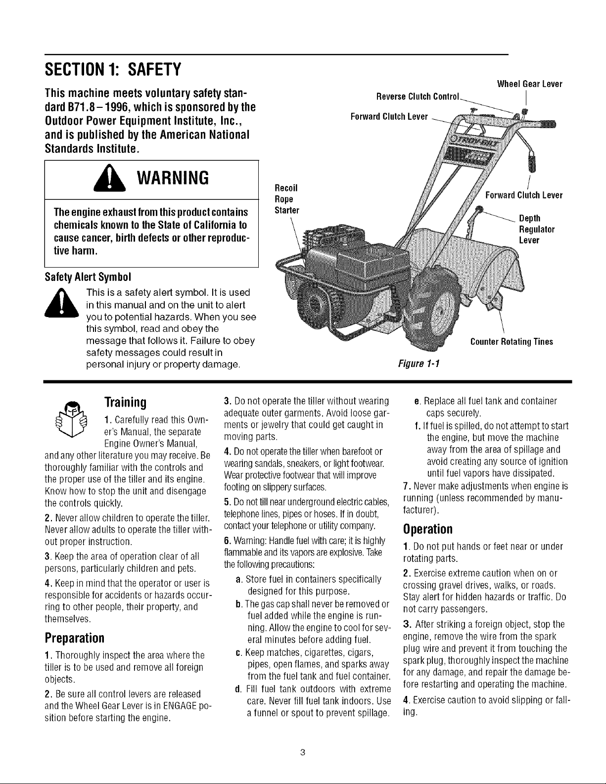
Wheel GearLever
ReverseClutch Control_ I
ForwardClutch Lever
WARNING
The engine exhaustfrom this productcontains
chemicals known to the State of California to
cause cancer, birth defects or other reproduc-
tive harm.
SafetyAlertSymbol
,_ This is a safety alert symbol. It is used
andanyotherliteratureyou mayreceive.Be
thoroughly familiar with the controls and
the proper use ofthe tiller and its engine.
Know howto stop the unit and disengage
the controls quickly.
2. Neverallow childrento operatethetiller.
Neverallow adultsto operatethetiller with-
out proper instruction.
3. Keepthe area of operationclear of all
persons, particularly children and pets.
4. Keepin mind that the operatoror user is
responsiblefor accidents or hazardsoccur-
ring to other people,their property, and
themselves.
Preparation
1. Thoroughly inspect the areawherethe
tiller is to be usedand removeall foreign
objects.
2. Besure allcontrol leversare released
andthe WheelGearLever isin ENGAGEpo-
sition beforestarting the engine.
in this manual and on the unit to alert
you to potential hazards. When you see
this symbol, read and obey the
message that follows it. Failure to obey
safety messages could result in
personal injury or property damage.
3. Donot operatethetiller without wearing
1. Carefullyreadthis Own-
Training
er's Manual,the separate
EngineOwner's Manual,
adequateouter garments. Avoid loosegar-
ments orjewelry that could getcaught in
moving parts.
4. Donotoperatethetillerwhenbarefootor
wearingsandals,sneakers,or light footwear.
Wearprotectivefootwearthatwill improve
footingonslipperysurfaces.
5. Donottillnearundergroundelectriccables,
telephonelines,pipesor hoses.If indoubt,
contactyour telephoneorutilitycompany.
6.Warning:Handlefuelwith care;itis highly
flammableandits vaporsareexplosive.Take
thefollowingprecautions:
a. Storefuel in containers specifically
b.Thegascapshall neverberemovedor
c. Keepmatches,cigarettes, cigars,
d. Fill fuel tank outdoors with extreme
Recoil
Rope
Starter
designedfor this purpose.
fuel addedwhile the engine is run-
ning.Allow theengineto coolfor sev-
eral minutes beforeadding fuel.
pipes, openflames, andsparksaway
from the fueltank and fuel container.
care. Neverfill fueltank indoors. Use
a funnel or spout to prevent spillage.
/
ForwardClutchLever
Depth
Regulator
Lever
CounterRotatingTines
Figl/re 1-1
e. Replaceall fueltank and container
caps securely.
f. If fuel isspilled, donot attemptto start
the engine,but move the machine
awayfrom the area of spillageand
avoidcreating anysource of ignition
until fuelvapors havedissipated.
7. Nevermakeadjustments whenengineis
running (unless recommendedby manu-
facturer).
Operation
1. Do not put hands orfeet near or under
rotating parts.
2. Exerciseextreme caution when on or
crossing gravel drives, walks, or roads.
Stay alertfor hidden hazardsor traffic. Do
not carry passengers.
3. After striking a foreign object, stop the
engine,remove thewire from the spark
plug wire and prevent it from touching the
spark plug,thoroughly inspectthe machine
for any damage,and repairthe damagebe-
fore restarting and operatingthe machine.
4. Exercisecautionto avoidslipping or fall-
ing.

5.Iftheunitshouldstarttovibrateabnormally,
stoptheengine,disconnectthesparkplug
wireandpreventitfromtouchingthespark
plug,andcheckimmediatelyforthecause.Vi-
brationisgenerallyawarningoftrouble.
6.Stoptheengine,disconnectthespark
plugwireandpreventitfromtouchingthe
sparkplugwheneveryouleavetheoperat-
ingposition,beforeuncloggingthetines,
orwhenmakinganyrepairs,adjustments
orinspections.
7.Takeallpossibleprecautionswhenleav-
ingthemachineunattended.Stoptheen-
gine.Disconnectsparkplugwireandmove
itawayfromthesparkplug.MoveWheel
GearLevertoENGAGE.
8.Beforecleaning,repairing,orinspect-
ing,stoptheengineandmakecertainall
movingpartshavestopped.Disconnect
thesparkplugwireandpreventitfrom
touchingthesparkplugtopreventacci-
dentalstarting.
9.Alwayskeepthetillertinehoodflap
down.
10.Neverusethetillerunlessproper
guards,plates,orothersafetyprotectivede-
vicesareinplace.
11.Donotrunengineinanenclosedarea.
Engineexhaustcontainscarbonmonoxide
gas,adeadlypoisonthatisodorless,col-
orless,andtasteless.
12.Keepchildrenandpetsaway.
13. Neveroperate thetiller underengine
powerif the WheelGearLever is in DIS-
ENGAGE(FREEWHEEL).Inthis position,
thewheels will notholdthe tiller back
andthe revolvingtines could propelthe
tiller rapidlybackward,possiblycausing
lossofcontrol. Always move theWheel
GearLeverto ENGAGEbefore starting the
engine or engagingthe tines4Nheelswith
the Forward Clutch or the ReverseClutch.
14. Beawarethat the tiller may unexpect-
edly bounceupward or jump backward if
the tines should strike extremely hard
packedsoil, frozen ground, or buried ob-
stacleslike largestones, roots, or stumps.
If in doubt aboutthe tilling conditions, al-
ways usethe following operating precau-
tions to assist you in maintaining control
of thetiller:
a. Walkbehindand to one sideof the
tiller, usingone handon thehan-
dlebars.Relax yourarm, butuse a
securehandgrip.
b. Use slower enginespeeds.
c. Clear thetilling areaof all large
stones,rootsand other debris.
d. Avoidusingdownwardpressureon
handlebars.If needbe, useslight
upwardpressureto keepthe tines
from diggingtoo deeply.
e. Beforecontacting hardpackedsoil
at the endof a row,reduceengine
speedand lift handlebarsto raise
tines out of thesoil.
f. In an emergency, stoptines and
wheels by releasingwhichever
ClutchLeverisengaged.Donotat-
temptto restrainthe tiller.
15. Donot overloadthe tiller's capacityby
attempting to till too deeplyat too fast a
rate.
16. Neveroperatethetiller at hightrans-
port speedsonslippery surfaces. Lookbe-
hind and use care when backing up.
17. Donot operatethetiller on aslopethat
is too steep for safety.When onslopes,
slow down and makesure you havegood
footing. Neverpermit thetiller to freewheel
down slopes.
18. Neverallow bystandersnearthe unit.
19. Onlyuse attachmentsand accessories
that are approved byGardenWay Inc.
20. Usetiller attachmentsandaccessories
when recommended.
21. Neveroperatethetiller withoutgoodvis-
ibility or light.
22. Neveroperatethetillerif youaretired,or
underthe influenceofalcohol,drugsormedi-
cation.
23.Operatorsshallnottamperwiththeengine-
governorsettingsonthemachine;thegovernor
controlsthemaximumsafeoperatingspeedto
protecttheengineandallmovingpartsfrom
damagecausedby overspeed.Authorizedser-
viceshallbesoughtif a problemexists.
24. Donottouchenginepartswhichmaybe
hotfromoperation.Letpartscooldown
25.Pleaseremember:Youcanalwaysstopthe
tinesandwheelsby releasingtheForward
ClutchLeverortheReverseClutchControl
(whicheverleveryou haveengaged)orbymov-
ingtheThrottleControlLeverto STOP.
26.Toloador unloadthetiller,seetheinstruc-
tionsinSection4ofthisManual.
27. Useextremecautionwhenreversingor
pullingthe machinetowardsyou.
28.Starttheenginecarefullyaccordingtoin-
structionsandwithfeetwellawayfromthe
tines.
29.Neverpickupor carryamachinewhilethe
engineis running.
MaintenanceandStorage
1. Keepthe tiller, attachmentsand acces-
sories in safeworking condition.
2. Checkall nuts, bolts, andscrews at fre-
quent intervalsfor proper tightness to be
surethe equipment is in safeworking con-
dition.
3. Neverstorethetillerwithfuelinthefueltank
insideabuildingwhereignitionsourcesare
presentsuchashotwaterandspaceheaters,
furnaces,clothesdryers,stoves,electricmo-
tors,etc.).Allowenginetocoolbeforestoringin
anyenclosure.
4.Toreducethechancesofafirehazard,keep
theenginefreeofgrass,leaves,or excessive
grease.
5. Storegasoline in acool, well-ventilated
area,safelyawayfrom any spark- orflame-
producingequipment. Store gasolinein an
approvedcontainer,safelyawayfrom the
reachof children.
6. Referto the storageinstructions in the
Maintenancesectionof this Manualandthe
separateEngineOwner'sManualfor in-
structions ifthe tiller is to be storedforan
extendedperiod.
7. Neverperformmaintenancewhiletheen-
gine is running orthe spark plugwire is
connected,exceptwhen specificallyin-
structedto do so.
8. If the fueltank hasto be drained,dothis
outdoors.
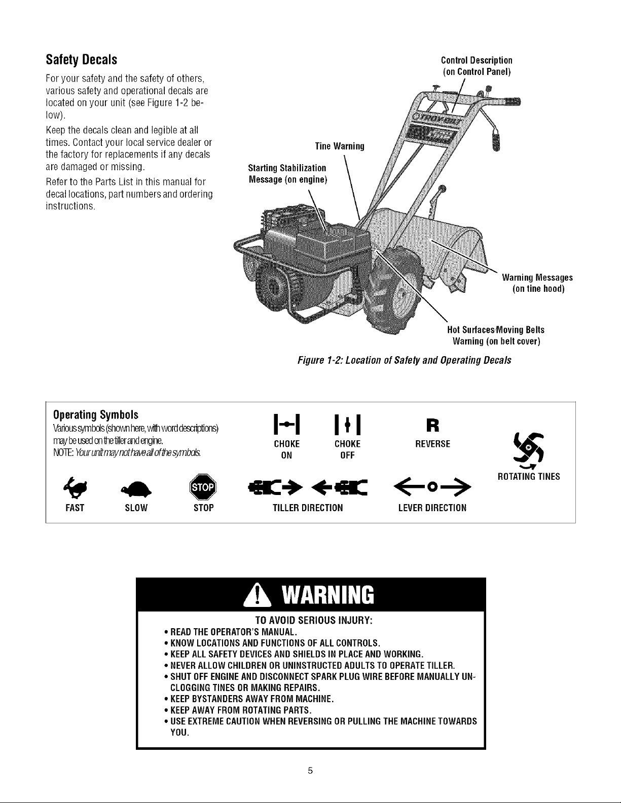
SafetyDecals
Foryour safety andthe safety of others,
various safety andoperationaldecals are
located on your unit (seeFigure 1-2be-
low).
Keepthe decalscleanand legible atall
times. Contactyour local service dealeror
the factory for replacementsif anydecals
are damagedor missing.
Referto the Parts List in this manual for
decallocations, partnumbersand ordering
instructions.
ControlDescription
(onControlPanel)
TineWarning
StartingStabilization
Message(onengine)
WarningMessages
(onlinehood)
HotSurfacesMovingBelts
Warning(onbeltcover)
OperatingSymbols
Varioussymbds(shownhere,withworddescriptions)
mayheusedon'dle'dllerandengine.
NOTE:Yourunitmaynothaveallof_esymbds.
FAST SLOW STOP
* READTHEOPERATOR'SMANUAL.
* KNOWLOCATIONSAND FUNCTIONSOFALLCONTROLS.
* KEEPALLSAFETYDEVICESANDSHIELDSIN PLACEANDWORKING.
. NEVERALLOWCHILDRENORUNINSTRUCTEDADULTSTO OPERATETILLER.
° SHUTOFFENGINEAND DISCONNECTSPARKPLUGWIREBEFOREMANUALLYUN-
CLOGGINGTINESORMAKINGREPAIRS.
. KEEPBYSTANDERSAWAYFROM MACHINE.
. KEEPAWAYFROM ROTATINGPARTS.
° USEEXTREMECAUTIONWHENREVERSINGOR PULLINGTHEMACHINETOWARDS
YOU.
Figure 1-2:Locationof Safetyand OperatingDecals
I-.-I I,I
CHOKE CHOKE
ON OFF
TILLERDIRECTION
TO AVOID SERIOUS INJURY:
R
REVERSE
ROTATINGTINES
<--
LEVERDIRECTION
SECTION2: ASSEMBLY
WARNING: Toprevent
personalinjury or property
damage,do notstartthe engine
until allassemblysteps are
completeandyou haveread
and understandthe safety and
operatinginstructions in this
Manual.
Introduction
Carefullyfollow these assemblysteps to
correctly prepareyour tiller for use. It is
recommendedthatyou readthis Sectionin
its entirety beforebeginning assembly.
Inspect unit
Inspect the unitand carton for damageim-
mediatelyafter delivery.Contactthe carrier
(trucking company) if you find or suspect
damage. Inform them of the damageand
request instructions for filing a claim. To
protect your rights, put your claim in writ-
ing and maila copyto the carrierwithin 15
days after the unit has beendelivered.
Contact usatthe factory ifyou needassis-
tance in this matter.
Unpackingand Assembly
Instructions
STEP1:UNPACKINGINSTRUCTIONS
1. Removeanycard-board inserts and
packaging materialfrom the carton. Re-
move anystaples from the bottom ofthe
carton and removethe carton.
2. Cutthe large,plastictie strapthat se-
curesthe transmissiontubeto theshipping
pallet. Leavethe handlebarson top ofthe
tiller to avoid damaginganycables.
3. Abag with loosehardware is inside the
literature envelope.Checkthe contents
againstthe following list and Figure2-1.
Contactyour local dealeror the factory if
anyitems are missing or damaged.
NOTE:Forelectric start units, a second
hardwarebag is locatednearthe battery.
4. Thetiller is heavy.Youshould not at-
tempt to removeit from the shipping plat-
form until instructed to do so in these
"Assembly" steps.
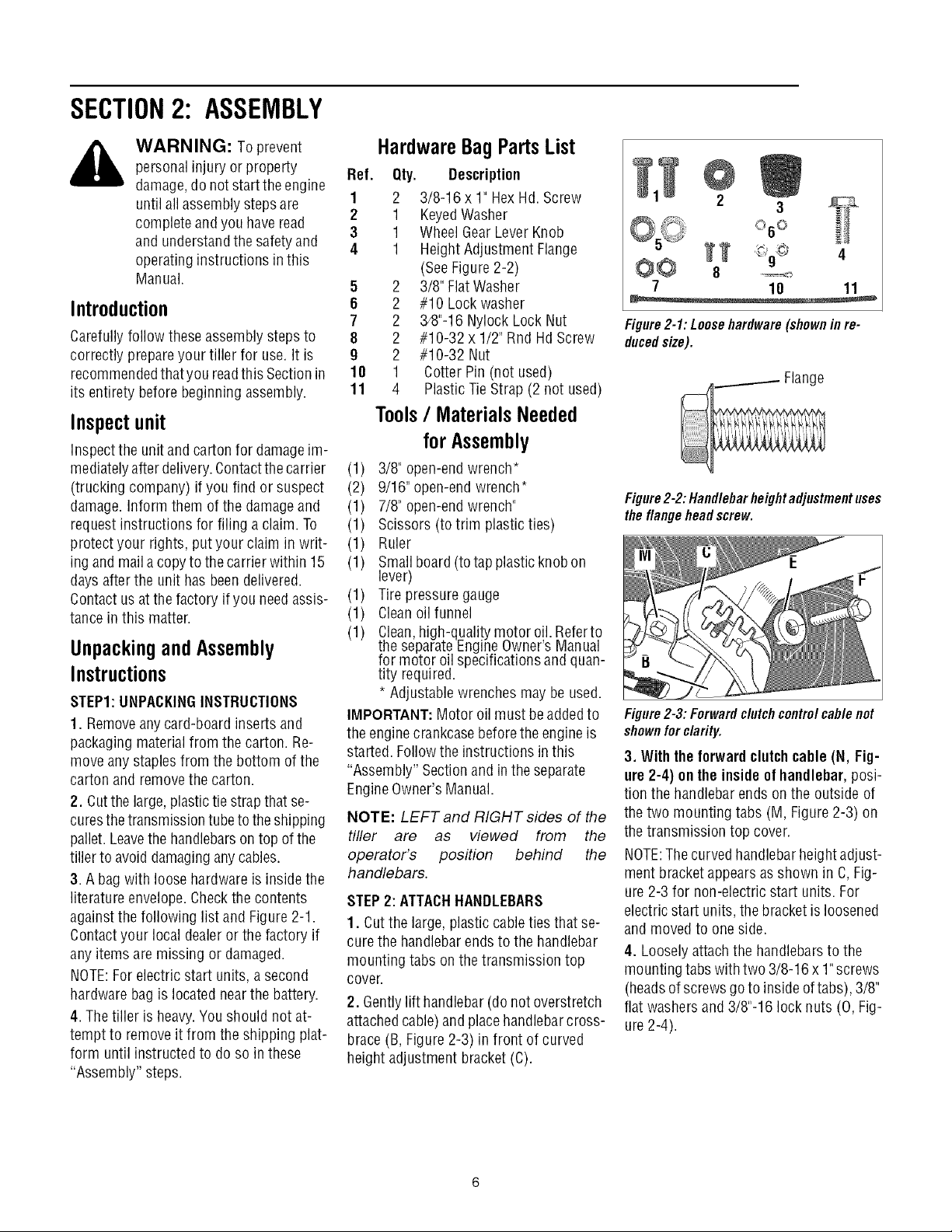
HardwareBagPartsList
Ref. Qty. Description
1 2 3/8-16 x 1" HexHd. Screw
2 1 KeyedWasher
3 1 WheelGearLeverKnob
4 1 Height Adjustment Flange
(SeeFigure2-2)
5 2 3/8" FlatWasher
6 2 #10 Lockwasher
7 2 3/8"-16Nylock Lock Nut
8 2 #10-32 x 1/2" Rnd HdScrew
9 2 #10-32 Nut
18 1 CotterPin (not used)
11 4 PlasticTieStrap (2 not used)
Tools/ MaterialsNeeded
forAssembly
(1) 3/8" open-endwrench*
(2) 9/16" open-endwrench*
(1) 7/8" open-endwrench"
(1) Scissors (totrim plasticties)
(1) Ruler
(1) Smallboard (totap plastic knobon
lever)
(1) Tirepressure gauge
(1) Cleanoil funnel
(1) Clean,high-quality motor oil. Referto
the separateEngineOwner'sManual
for motor oil specificationsand quan-
tity required.
* Adjustablewrenchesmay be used.
IMPORTANT:Motor oil must beaddedto
the enginecrankcasebeforethe engine is
started. Followthe instructions inthis
"Assembly" Sectionand in the separate
EngineOwner'sManual.
NOTE: LEFT and RIGHT sides of the
tiller are as viewed from the
operator's position behind the
handlebars.
STEP2: ATTACHHANDLEBARS
1. Cutthe large, plastic cableties that se-
curethe handlebarends to the handlebar
mounting tabs onthe transmission top
cover.
2. Gentlylift handlebar(do not overstretch
attachedcable) and placehandlebarcross-
brace(B, Figure2-3) in front of curved
height adjustmentbracket (C).
4
O@ 8
7 10 11
Figure2-1:Loosehardware(shownin re-
ducedsize).
Figure2-2: Handlebarheightadjustmentuses
the flangehead screw.
Figure2-3:Forwardclutchcontrolcablenot
shownforclarity.
3. Withtheforwardclutchcable (N, Fig-
ure 2-4) ontheinside of handlebar,posi-
tion the handlebarends onthe outside of
thetwo mounting tabs (M, Figure 2-3) on
thetransmission top cover.
NOTE:Thecurved handlebarheightadjust-
ment bracket appearsas shown in C, Fig-
ure 2-3 for non-electric start units. For
electricstart units, the bracketisloosened
and moved to one side.
4. Loosely attach the handlebarsto the
mounting tabs withtwo 3/8-16 x 1"screws
(headsof screws goto inside of tabs), 3/8"
flat washersand 3/8"-16 lock nuts (O, Fig-
ure2-4).
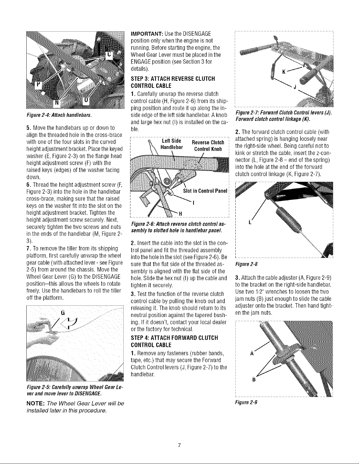
Figure2-4: Attachhandlebars.
5. Move the handlebarsup or downto
align thethreaded hole in the cross-brace
with one of thefour slots in the curved
heightadjustment bracket.Placethekeyed
washer (E, Figure2-3) on the flange head
height adjustmentscrew (F)with the
raised keys(edges)of the washerfacing
down.
6. Threadthe height adjustment screw (F,
Figure2-3) into the holein the handlebar
cross-brace, makingsurethat the raised
keyson the washerfit intothe slot on the
height adjustmentbracket. Tightenthe
height adjustmentscrew securely.Next,
securelytighten thetwo screws and nuts
in the ends of the handlebar (M,Figure2-
3).
7. Toremovethe tiller from its shipping
platform, first carefully unwrap the wheel
gearcable(with attached lever- seeFigure
2-5) from around the chassis. Movethe
WheelGearLever(G) to the DISENGAGE
position--this allows the wheelsto rotate
freely. Usethe handlebarsto roll the tiller
off the platform.
IMPORTANT:Usethe DISENGAGE
position onlywhenthe engineis not
running. Beforestartingthe engine,the
WheelGear Levermust be placedin the
ENGAGEposition (seeSection3 for
details).
STEP3: ATTACHREVERSECLUTCH
CONTROLCABLE
1. Carefullyunwrap the reverseclutch
control cable(H, Figure 2-6) from its ship-
ping position and route it upalong the in-
sideedgeofthe left sidehandlebar.Aknob
and large hexnut (I) is installed on theca-
ble.
Left Side ReverseClutch
Handlebar Control Knob
SlotinControlPanel
'1
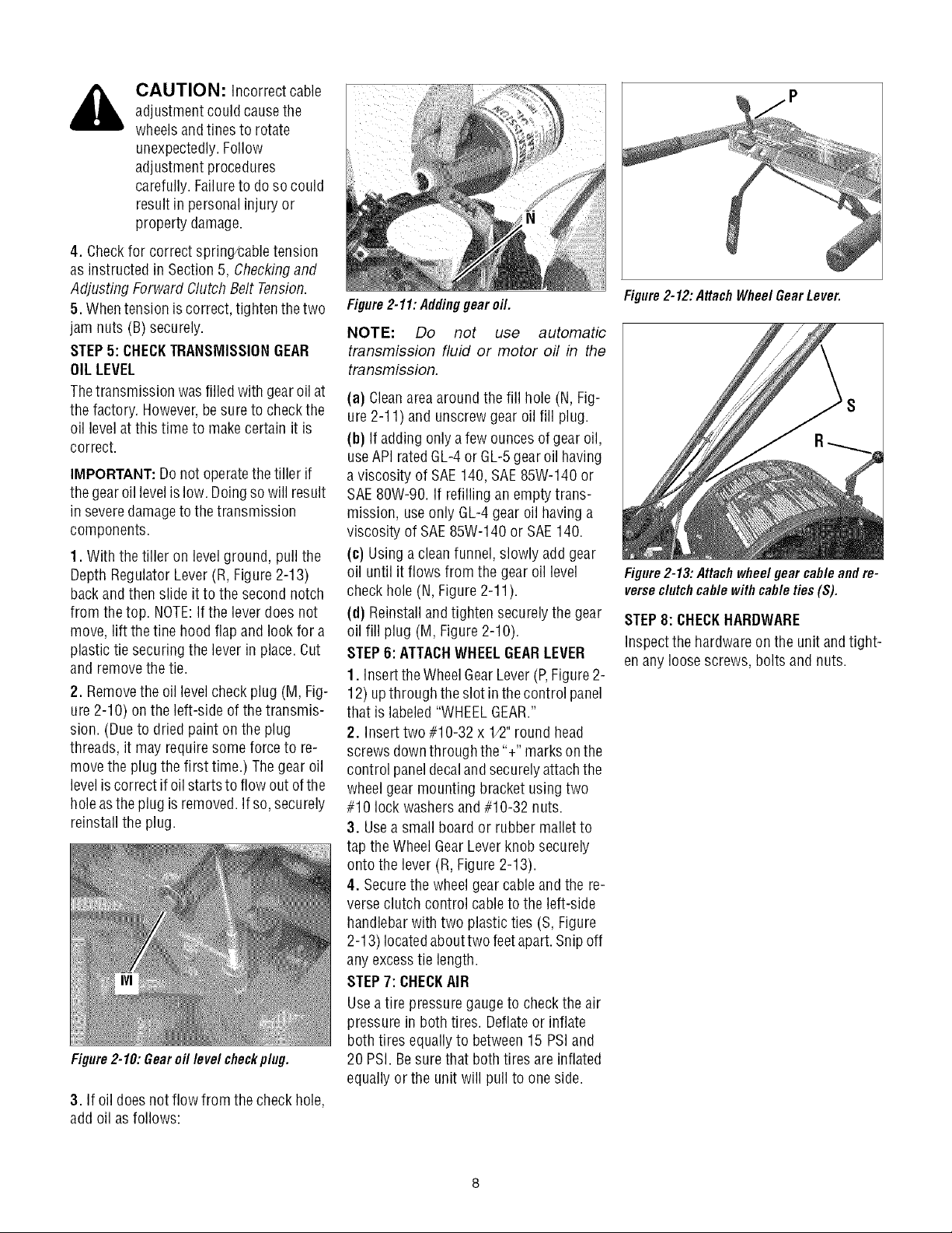
Figure2-6:Attachreverseclutchcontrolas-
semblytodotted holeinhandlebarpanel.
2. Insert the cableinto the slot inthe con-
trol paneland fit the threaded assembly
intothe holein theslot (seeFigure2-6). Be
surethat the flat sideof the threaded as-
sembly is aligned with theflat side of the
hole.Slide the hexnut (I) upthecable and
tighten it securely.
3. Testthe function ofthe reverseclutch
control cableby pulling the knob out and
releasingit. Theknob should return to its
neutral position againstthe taperedbush-
ing. If it doesn't, contact your local dealer
or the factory for technical.
STEP4: ATTACHFORWARDCLUTCH
CONTROLCABLE
1. Removeany fasteners (rubber bands,
tape, etc.) that may securethe Forward
ClutchControl levers(J, Figure 2-7) to the
handlebar.
Figure2-7: ForwardClutchControllevers(J).
Forwarddutch controllinkage (K).
2. Theforward clutch control cable (with
attachedspring) is hanging looselynear
the right-side wheel. Beingcareful not to
kink or stretch the cable,insert the z-con-
nector (L, Figure2-8 - end of the spring)
into the hole atthe end ofthe forward
clutch control linkage(K, Figure2-7).
Figure2-8
3. Attachthecableadjuster (A, Figure2-9)
to the bracketon the right-side handlebar.
Usetwo 1/2"wrenchesto loosenthe two
jam nuts (B)just enoughto slidethe cable
adjuster ontothe bracket.Then handtight-
enthe jam nuts.
Figure2-5:CarefullyunwrapWheelGearLe-
verandmoveleverto DISENGAGE.
NOTE: The Wheel Gear Lever will be
installed later in this procedure.
Figure2-9
CAUTION: Incorrect cable
adjustment couldcausethe
wheelsandtines to rotate
unexpectedly.Follow
adjustment procedures
carefully. Failureto dosocould
result in personal injury or
property damage.
4. Checkfor correct spring/caNetension
as instructedin Section 5, Checkingand
Adjusting Forward Clutch Belt Tension.
5. Whentension is correct, tightenthe two
jam nuts (B) securely.
STEP5: CHECKTRANSMISSIONGEAR
OILLEVEL
Thetransmission was filled with gearoil at
the factory. However,besure to checkthe
oil levelatthis time to makecertain it is
correct.
IMPORTANT:Do not operatethe tiller if
the gearoillevelislow. Doingso will result
in severedamagetothe transmission
components.
1. With the tiller on level ground, pull the
Depth Regulator Lever(R, Figure 2-13)
backand then slide it to the second notch
from thetop. NOTE:Ifthe lever does not
move, lift thetine hood flapand look for a
plastic tie securing the lever in place.Cut
and removethe tie.
2. Removethe oil levelcheck plug (M, Fig-
ure 2-10) on the left-side of thetransmis-
sion. (Dueto dried paint onthe plug
threads, it mayrequire some forceto re-
move the plug the first time.) Thegear oil
levelis correct if oilstarts to flow out ofthe
holeastheplug isremoved.If so, securely
reinstall the plug.
Figure2-10: Gear oil level checkplug.
3. If oil doesnot flow from the checkhole,
add oil as follows:
Figure2-11:Addinggearoil.
NOTE: Do not use automatic
transmission fluid or motor oil in the
transmission.
(a) Cleanareaaround the fill hole (N, Fig-
ure 2-11) and unscrewgear oil fill plug.
(b) If adding onlya fewounces ofgear oil,
useAPI rated GL-4or GL-5gearoil having
a viscosity of SAE140, SAE85W-140 or
SAE80W-90. If refilling an emptytrans-
mission, useonly GL-4gear oil havinga
viscosity of SAE85W-140 or SAE140.
(c) Using aclean funnel, slowly add gear
oil until it flows from the gear oil level
checkhole (N, Figure 2-11).
(d) Reinstalland tighten securelythe gear
oil fill plug (M, Figure2-10).
STEP6: ATTACHWHEELGEARLEVER
1. Insertthe WheelGearLever(P,Figure2-
12) upthrough theslot in thecontrol panel
that is labeled"WHEELGEAR."
2. Insert two#10-32 x 1/2"round head
screws downthrough the'%" marks onthe
control paneldecalandsecurelyattachthe
wheelgear mounting bracket usingtwo
#10 lock washersand #10-32 nuts.
3. Usea small board or rubber malletto
tap the Wheel GearLever knob securely
onto the lever (R, Figure2-13).
4. Securethe wheelgear cable and the re-
verseclutch control cableto the left-side
handlebarwith two plastic ties (S, Figure
2-13) locatedabouttwo feetapart.Snip off
anyexcesstie length.
STEP7: CHECKAIR
Usea tire pressuregauge to checkthe air
pressure in both tires. Deflateor inflate
both tires equallyto between15 PSiand
20 PSI. Besure that both tires are inflated
equallyor the unit will pull to one side.
Figure2-12: Attach Wheel GearLever.
Figure2-13:Attachwheelgearcableandre-
verseclutchcablewithcableties(S).
STEP8: CHECKHARDWARE
Inspectthe hardwareon the unit andtight-
en anyloose screws, boltsand nuts.
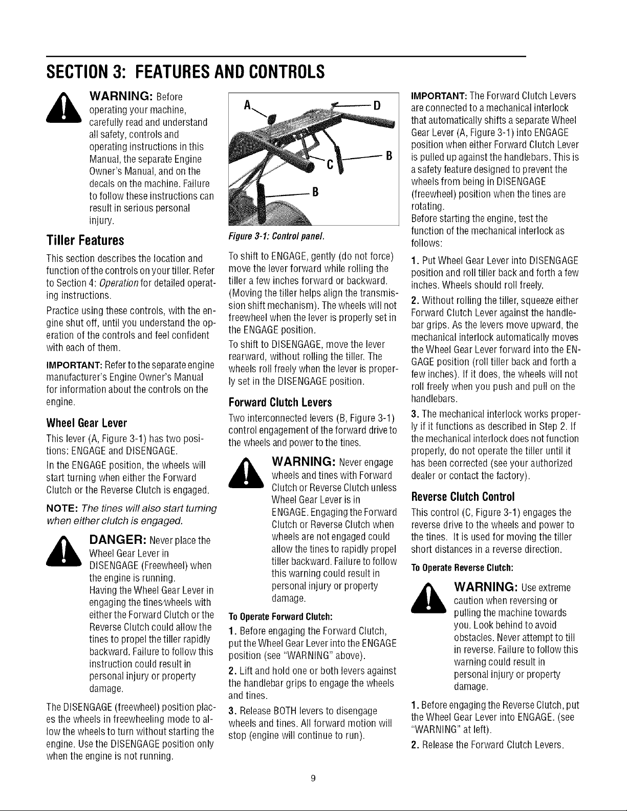
SECTION3: FEATURESANDCONTROLS
_ ARNING: Before
Tiller Features
This section describesthe locationand
function ofthecontrols on yourtiller. Refer
to Section4: Operationfor detailedoperat-
ing instructions.
Practice usingthese controls, with the en-
gine shut off, until you understandthe op-
eration ofthe controls and feel confident
with eachof them.
IMPORTANT:Referto theseparateengine
manufacturer's EngineOwner's Manual
for information about thecontrols onthe
engine.
Wheel Gear Lever
This lever (A,Figure3-1) hastwo posi-
tions: ENGAGEand DISENGAGE.
In the ENGAGEposition, the wheelswill
start turning when either the Forward
Clutch orthe ReverseClutch is engaged.
NOTE: The tines will also start turning
when either clutch is engaged.
,_ DANGER: Neverplacethe
TheDISENGAGE(freewheel)position plac-
esthe wheels infreewheeling modeto al-
low thewheelsto turn without starting the
engine.Usethe DISENGAGEposition only
whenthe engine is not running.
operatingyour machine,
carefully readand understand
all safety,controls and
operatinginstructions in this
Manual,the separateEngine
Owner's Manual,andon the
decalson the machine.Failure
to follow these instructions can
result in serious personal
injury.
WheelGearLever in
DISENGAGE(Freewheel)when
the engineis running.
HavingtheWheelGearLeverin
engagingthetines_vheelswith
eitherthe Forward Clutchorthe
ReverseClutch couldallow the
tines to propel thetiller rapidly
backward.Failureto follow this
instruction could result in
personalinjury or property
damage.
Figure3-1: Controlpanel.
Toshift to ENGAGE,gently (do not force)
move the leverforward while rolling the
tiller afew inches forward or backward.
(Moving thetiller helpsalign the transmis-
sionshift mechanism). Thewheelswill not
freewheelwhenthe leveris properly setin
the ENGAGEposition.
Toshift to DISENGAGE,move the lever
rearward, without rolling the tiller.The
wheels roll freelywhen the leveris proper-
ly setin the DISENGAGEposition.
ForwardClutchLevers
Twointerconnected levers (B, Figure3-1)
control engagementofthe forward driveto
the wheelsandpowerto the tines.
,_ WARNING: Neverengage
ToOperateForwardClutch:
1. Beforeengagingthe ForwardClutch,
putthe Wheel GearLeverintothe ENGAGE
position (see "WARNING"above).
2. Lift and holdone or both leversagainst
the handlebargrips to engagethe wheels
andtines.
3. ReleaseBOTHleversto disengage
wheelsand tines. All forward motion will
stop (engine will continue to run).
wheelsandtines with Forward
Clutchor ReverseClutchunless
WheelGearLever is in
ENGAGE.EngagingtheForward
Clutchor ReverseClutchwhen
wheelsare not engagedcould
allowthe tinesto rapidly propel
tiller backward.Failureto follow
this warning could result in
personalinjury or property
damage.
IMPORTANT:The ForwardClutch Levers
areconnectedto amechanicalinterlock
that automaticallyshifts a separateWheel
GearLever(A,Figure3-1) into ENGAGE
position when eitherForwardClutch Lever
is pulledupagainstthe handlebars.This is
asafety featuredesignedto preventthe
wheelsfrom being in DISENGAGE
(freewheel)position when the tines are
rotating.
Beforestarting the engine,testthe
function ofthe mechanicalinterlock as
follows:
1. PutWheel GearLeverinto DISENGAGE
position and roll tiller backand forth a few
inches.Wheels should roll freely.
2. Without rollingthe tiller, squeezeeither
Forward Clutch Leveragainst the handle-
bargrips. Asthe levers move upward,the
mechanicalinterlock automatically moves
theWheel GearLeverforward into the EN-
GAGEposition (roll tiller backand forth a
few inches). If it does,the wheels will not
roll freely whenyou push and pull on the
handlebars.
3. The mechanicalinterlock works proper-
ly if it functions as describedin Step 2. If
themechanical interlock does not function
properly, do not operatethe tiller until it
hasbeencorrected (seeyour authorized
dealeror contact the factory).
Reverse Clutch Control
This control (C,Figure3-1) engagesthe
reversedrive to the wheels andpower to
thetines. It is usedfor moving thetiller
short distances in a reversedirection.
ToOperateReverseClutch:
_ ARNING: Useextreme
1. Beforeengagingthe ReverseClutch,put
theWheel GearLever into ENGAGE.(see
"WARNING"at left).
2. Releasethe Forward ClutchLevers.
caution whenreversing or
pulling the machinetowards
you. Look behindto avoid
obstacles.Neverattemptto till
in reverse.Failureto follow this
warningcould result in
personalinjury or property
damage.

3.Tomovethetillerinreverse,firststopall
forwardmotion.Liftupthehandlebarsun-
tilthetinesclearthegroundandpullthe
ReverseClutchleverout.
Thewheelswillrotateinareversedirection
aslongastheleverisheldinREVERSE.To
stopthewheelsandtines,releasethelever
anditwillreturntoNEUTRAL.Neverat-
temptto till whilemovingin reversedi-
rection.
DepthRegulatorLever
This lever (E,Figure3-2) controls the till-
ing depthof the tines. Pullthe lever
straight backandslide it upor downto en-
gagethe notchedheight settings.
Figure3-2:DepthRegulatorLever.
Thehighest notch(leverall the way down)
raisesthe tinesapproximately1-1/2inches
off the ground. This"travel" position al-
lows the tiller to bemoved without the
tines digging into the ground.
Moving the lever up increasesthetilling
depth. Thelowest notch allows a tilling
depthof approximatelysix to eight inches,
dependingon soil conditions.
Forbest results, always begin tilling at a
very shallow depth setting and gradually
increasetilling depth.
Handlebar HeightAdjustment
Handlebarheight is adjustableto four dif-
ferent settings. Whensetting the height,
keepin mindthat the handlebarswill be
lower whenthe tines areengagedin the
soil.
WARNING: Wheneverthe
handlebarheight ischanged,
the ForwardClutchshift
mechanism must be
readjusted.Beforeadjusting or
checkingthe ForwardClutch
mechanism,shut engineoff,
disconnect spark plugwire and
prevent itfrom touching spark
plug. Failureto follow this
warningcould causethe
ForwardClutch mechanismto
operateimproperly which could
result in personal injury or
property damage.
ToAdjustHandlebarHeight:
1. Stopengine, wait for all parts to stop
moving andthen disconnectspark plug
wire.
2. Loosenthe two screws atlower endsof
handlebar.
3. Loosenheight adjustment screw (F,Fig-
ure 3-3) and pull keyedwasher (G)free
from slots in curved height adjustment
bracket.
EngineControls
IMPORTANT:Theengineis equippedwith
eithera chokecontrol ora primer bulb.
Referto the EngineOwner's Manual(in-
cluded intiller literature package)to iden-
tify which deviceis on your engine.
Recoil Starter
Therecoil starter (H, Figure3-4) is usedto
"pull-start" theengine.SeeEngineStarting
and Stopping in Section4 for detaileden-
gine starting instructions.
H
Figure3-4: Recoil starter handle.
EngineThrottle Lever
Thethrottle lever (D, Figure3-1) is usedto
adjust enginespeedas wellas stop the en-
gine. Usethe STARTposition whenstart-
ing the engine. Pullthe lever all way back
tothe STOPpositionto shut the engineoff.
,_ WARNING: PlaceDepth
to follow this warning could result in
personalinjury or property damage.
Regulator Leverin "travel"
position beforestarting engine.
This position preventsthetines
from touching the ground until
you arereadyto begintilling .Do
notattempt to till too deeplytoo
quickly. Graduallywork down
to deepertilling depths.Failure
Figure3-3: Handlebarheight adjustment.
4. Move handlebarsto a new slot setting
and insert the raisedkeyon the keyed
washer intothe slot. Tightenthe heightad-
justment screw securely.
5. Retightenthe two screws atends of
handlebar.
lO
SECTION3: OPERATION
WARNING: Before
operatingyour machine,
carefully readand understand
all safety (Section1),controls
(Section 3) andoperating
instructions (Section4) inthis
Manual,in the separateEngine
Owner's Manual,andon the
decalson the machine.Failure
to follow these instructions can
result in serious personal
injury.
Introduction
Readthis Section of the manualthorough-
ly beforeyou start the engine.Then,take
time to familiarizeyourself with the basic
operation of the tiller before using it. Find
an open, levelareaand practiceusing the
tiller controls without engagingthe tines in
the soil (put tines in "travel" setting). Only
after you've becomecompletely familiar
with thetiller should you begin using it in
the garden.
Break-In Operation
Perform thefollowing maintenanceduring
the first hours of newoperation (seeSec-
tion 5: Maintenanceandthe maintenance
section of the EngineOwner'sManual).
1. Changemotor oil after first 2 hours of
newengine operation.
2. Checkfor loose or missinghardwareon
unit. Tighten or replaceas needed.
3. Checktension on forward drive belt af-
ter first 2 hours of operation.
4. Checktransmission gear oil levelafter
first 2 hours of operation.
STARTING AND STOPPING ENGINE
Thefollowing steps describehow to start
and stop the engine. Donot engagethe
tinesorwheels untilyouhavereadall of
theoperatinginstructionsinthisSection.
Alsoreviewthe safetyrules in Section1:
Safetyand the tiller andenginecontrols
informationin Section3: Featuresand
Controls.
Pre-StartChecklist
Dothe following beforestarting the en-
gine.
1. Checkunit for looseor missing hard-
ware. Serviceas required.
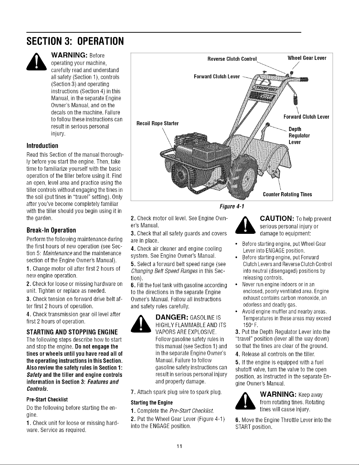
ReverseClutchControl
ForwardClutchLever
RecoilRopeStarter
Figure4-1
2. Checkmotor oil level.SeeEngineOwn-
er's Manual.
3. Checkthat allsafety guards andcovers
are in place.
4. Checkair cleanerand enginecooling
system. SeeEngineOwner's Manual.
5. Selectaforward belt speedrange (see
ChangingBelt SpeedRangesin this Sec-
tion).
6. Fillthefueltank with gasolineaccording
to the directions inthe separate Engine
Owner's Manual.Follow allinstructions
and safety rules carefully.
_k ANGER: GASOLINEIS
7. Attachspark plug wire to spark plug.
Startingthe Engine
1. Completethe Pre-Start Check/isL
2. Putthe WheelGear Lever(Figure4-1)
into the ENGAGEposition.
HIGHLYFLAMMABLEAND ITS
VAPORSAREEXPLOSIVE.
Followgasolinesafety rules in
this manual (seeSection 1)and
in the separateEngineOwner's
Manual.Failureto follow
gasolinesafety instructions can
result in seriouspersonalinjury
and property damage.
WheelGearLever
/
\
ForwardClutchLever
Depth
Regulator
Lever
CounterRotatingTines
_, AUTION: To helpprevent
• Beforestartingengine,putWheelGear
• Beforestartingengine,putForward
• Neverrunengineindoorsor inan
• Avoid enginemufflerand nearbyareas.
3. Putthe DepthRegulatorLeverinto the
"travel" position (lever all the way down)
sothat the tinesare clear ofthe ground.
4. Releaseall controls on the tiller.
5. If the engine is equipped with afuel
shutoff valve,turn the valveto the open
position, asinstructed in the separateEn-
gine Owner's Manual.
_ WARNING: Keepaway
6. Movethe EngineThrottle Leverinto the
STARTposition.
serious personalinjury or
damageto equipment:
LeverintoENGAGEposition.
ClutchLeversandReverseClutchControl
intoneutral (disengaged)positions by
releasingcontrols.
enclosed,poorlyventilatedarea.Engine
exhaustcontainscarbonmonoxide,an
odorlessanddeadlygas.
Temperaturesintheseareasmayexceed
150oF.
from rotating tines. Rotating
tines will causeinjury.
11
 Loading...