

Troybilt 21A-675B063 Owner’s Manual

_i_)iiiiiiiiiiiiiiiiiiiiiiiiiiiiiiiiiiiiiiiiiiiiii
Rear, tineTillerModel
M0del 675B ShOwn(bumper sy!eSVa_)
I MPO RTANT:READ SAFETY RUL ES AND INSTRUCTIONS CAR EFULLY
Warning: This unit is equipped with an interna ! combustion engine and shou!d not be used on or near any un!mproved forest-covered; brush-
covered or grass-covered land unless the eng!nels exhaust system !sequip_d with a spark arrester meet!ng app]!cab!e Iota! or state laws (if any) i
!f a spark arrester is used, !t shou!d be maintained in effect_e working order by the operatori In the State of California the above is requ!red by law
(Sect!on 4442 of the California Pub!ic Resources Code)i Other states may have s!mi!ar !awsi Federa! !aws apply on federal landsi A spark arrester
for the muff!er is ava!lab!e by contacting the service department at Troy-Bi!t LLC; PiOi Box 361131 Cleveland, Ohio 44136-0019i
TROY-BILT LLC, ROi BOX 361131i CLEVELAND, OH 44136,0019
PRINTED IN USA FROM NO: 769,00586
TABLEOFCONTENTS
Content Page
Calling Customer Support : : i i..i i :: : : i i.i i : :: : i i..i i : : : i i i.i i : : : : i i.i i i :: :2
Safety::::.i;:; ; ; ; ; ;; ;:3
Assemblyi i. i ; i ; ; ; ; ; ;; ; i6
Features and Controls:.:::;: : : :..: : : : : : : :.: : : :: : : :..: : : : : : : :.: : : : : : : :.: : : : : :8
Operation : : : : : :: : :t t
Maintenance iii ; iiii.iiii; iii..iii; iiii.iiii; iii.iiii; iiii.iii;; iii.iiii; it6
Troubleshooting ::::i.;;;::::i..;;:::::i.;;:::::i.;;;::::ii.;;:::::i.;;;::;22
Parts List : : : : : : : :24
War,any Information : :. i i i :; ; ; ; ;; ; :Back Co_er
FINDING
This Operator's Manual is an important part of your new Rear,tine Tillerilt will help you assemble; prepare and main,
tain the unit for best performance: Please read and understand what it says:
Before you start assem bling you r new eq uipment; please locate the model plate on the equipment and copy the infor,
mation from it in the space provided below: This information is ve_ important if you need help from our Customer
Support Department oKan authorized dealeri
• You can locate the model number by looking at the rear surface of the tine shield: A sample model plate is
explained below. For futu re refefence; please copy the model number and the serial number of the equipment
in the space below
Copy Model Number Here
www:t rovbilt:com CLEVELANDi0H44136
_ 866-840-6483
_ 330;558,7220
ENGINEINFORMATION
_he engine manufacturer is responsible for all engine-related issues with regards to performance; power-_ating, speci-
ficationsi warranty and servicei Please refer to the engine manufactureCs Owner's/Operator's Manual packed sepa,
rarely with your unit for more informationi
CALLINGCUSTOMER
If you have difficulty assembling this product or have any questions regarding the controls; operation or maintenance
of this unit, please call the Customer Support Department;
Call 1-(330)558,7220 or 1, (866) 840-6483 to reach a Custome r Support representativei Please have
'_ your unit!s model number and serial number ready when you Call:See previous section to locate this infor,
mationi You will be asked to enter the seiial numbei in oidei to piocess your call
SPARK ARRESTER WARNINGTO RESIDENTS OF
CALIFORNIAAND SEVERALOTHERSTATES
Under Oalifornialawiand Under the laws of several
other states; you are not permitted to operate an inter.
halcombustion engine usinghyd rocarbon fuels on any
foresL brushi hay;grainiorg rass covered land;or land
Covered by any flammable agtic ultural Ctop without an
engine spark arrester in continuous effective working
order.
Theengine on theunit is aninternal cornbustionengine
which burns gasolinei a hydrocarbon fueli and must be
eq uipped with aspark arrester muffler in continuous
effective working orderi The spark arrester must be
attached to the engine exhaust sYstem in such a
manner that flames or heatfrom the system willnot
ignite flammable material: Failureof the owner/opera-
tor of the unit to cornply with this regulation is a mis,
demeanor under California law (and other states) and
may also be a violation of other state and!or federal
reg ulations, laws; ordinances or codesi Conrad your
localfi remarshal or forest servicefor specific informa,
tion aboutwhich regulations apply inyour area.
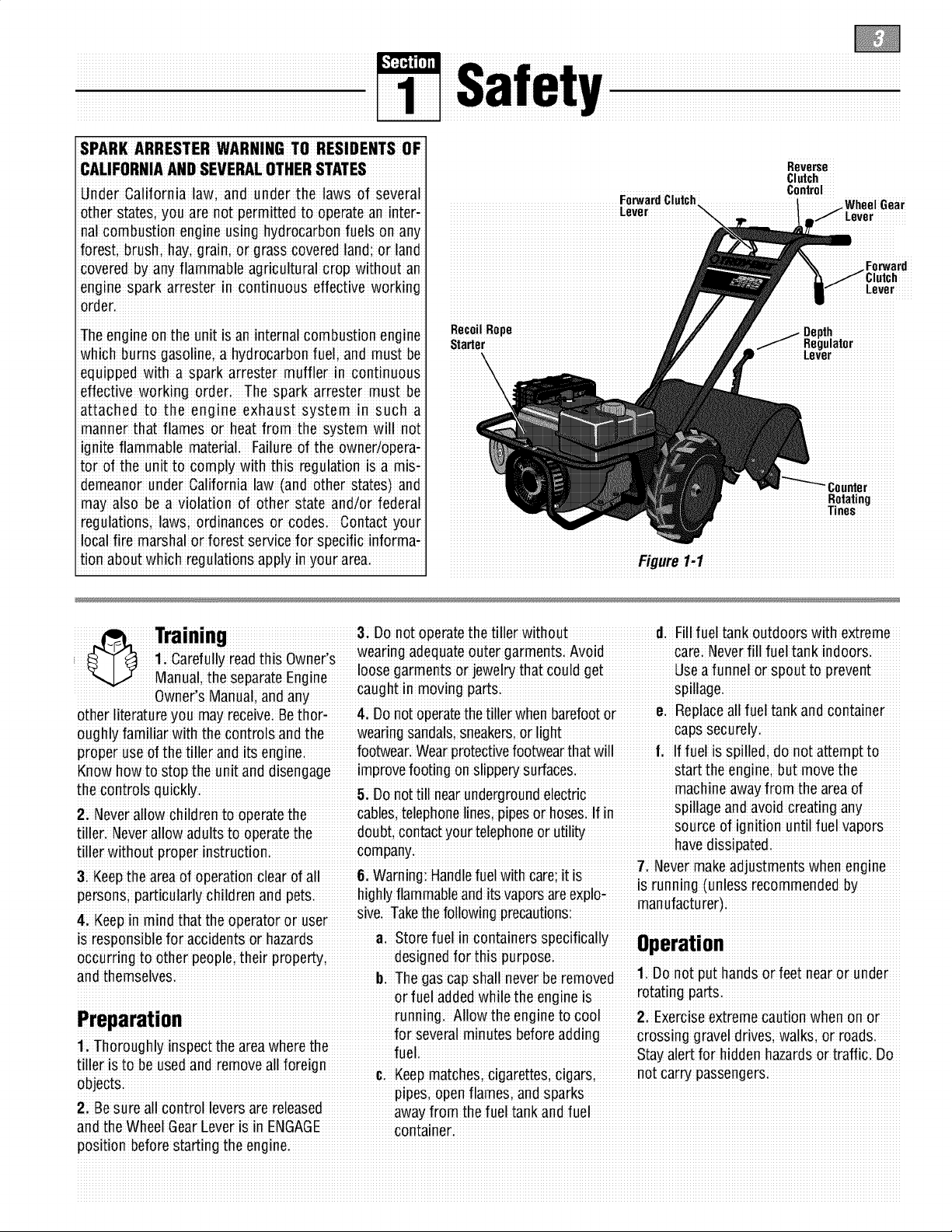
Reverse
Clutch
ForwardClutch i ...... luh,,,, n,,_,_
Leve I ..............
RecoilRope
Starter lulator
Control
Forward
iiiiiiiiiiiiil
Rotatingiiiiiiii
Tines
iiiiiiiiiiiiiiiiiiiiiiiiiiiiiiiiiiiiiiiiiiiiiiiiiiiiiiiiiiiiiii_urei1i.1iiiiiiiiiiiiiiiiiiiiiiiiiiiiiiiiiiiiiiiiiiiiiiiiiiiiiiiiiiiiiiii
h
Training 3: Donot operatethe tiller without d. Fill fuel tankoutdoorswith extreme
1 r f ii-i ihi wn r, wear'ng adequateouter garmentS Avo'd care Neverf ' fue tank'ndoors
,,Ca e u y Bad sO e
Manual, the separateEngine ........ .......
............... wnii Mn I nd n................caught in moving parts...........................................................spillage............................................................
0 e s ia ua,a a
other literature you may receive Bethori 4: Donotoperatethetiller whenbarefootore. Replaceall fuel tank andcontainer
oughlyfamiliar with the controls and the wear ngsandals;Sneakersior light capssecurely
proper useof the tiller andits engine: footwear.Wearprotectivefootwear that will l, lffuel is spilledi donor attempt to
Know how to Stopthe unit and disengage improvefooting onslippe_ surfaces, start the enginei butmove the
thecontrols .machine away from the areaof
• 5, Donott!ll nearundergroundelectnc :
2, Neverallow children to operatethe cables,telephone nesiplpeso hose& If n,, : :
iiller Neverallow adultsto operatethe doubt contactyourtelephoneor utility !
r': r coman havedissipated
tille withoutproperlnstuctloni P Yi _ i i ,: il i i :
&Keep the areaof operation clearof all&Warning: Handlefuelwith care;it isis r_nnin" _unless"_ _"_'_ _:
pe#sons;pa#ticuladychildren and pets highlyflammableanditsvaporsareeXplo; _, ;,_; ;_
4 KeG inmin thtth oertor r......er..........slve taKe[neToliowlngprecau1:ions..............................................................................................................
p d a: e p a: o us
is responsiblefor accidentsor hazards a; Storefuel in containers specifically 88eratiGn
occurring to other people;their property; designedfor th s purposei _,-c--_-_
and themselves Th h II n v r r m v 1 Donot put hands or feet nearor under
i iii i i!. b; egascapsiaii ieeibe e ioed.
............. ........ running AIIow the engine to cool 2 ExerciseextremeCautionwhen onor
Preparation ...... ............
1/horoughly inspect the areawherethe
fue Stay alertfor hidden hazardsor traffic. Do
; i. for several rainutes beforeadd gravel drives; walksi or roads
tiller is to beused andremove all foreign _ _L_LL_ Li_L_L_,._ not cai"' _assen'_ers
UUJUUL;5.............................................................................................. ....................................................................................................................................................................
2; Be Sureall control leversare released awayfrom thefuel tank andfuel
andihe WheelGearLe_er iSin ENGAGE cont'aineri
position beforestarting the engine.
loosegarmentsor ]ewel_ that could get Useafunnel or spout toprevent
li' r i spillage ariaavOIOcrea:lngany.............
source of ignition until fuel vapors
. : ; t\Jevermake aejusl:menl:swnen engine
g _ ruuul_mluuuuu uy
÷ _. I I IdllU_dbLU EUE,li
or fueladded while the engine iS rotat!ngparts.
pipes,open flamesi and
3. After striking a foreign object, stopthe 14: Beawarethat the tiller may unexpeCb Speed:Authorizedserviceshallbesoughtif
engirle,remove the wire from the ;spark edly bounceupward or jump backward if a problemexistsi
plug wire and preVentit from touchingthe thetinessh ould strikeextremel!i hard 24 DonoitouchengineDa_swhichmavbe
spark plugi thoroughly respectthe packedsoil, frozengroundi or buried hoifrom oDerationiLet Da2rtscool down
machinefor any damagei and repair the obstacles likelarge stones, roots; or sufficientli
damagebefore restart!ng and operating stumps; If !ndoubt about the t!lhng cond!-L _
the machinei tionsi alwaysuse thefollowing operating 2_i _!easeremem_e_:_ou cana_waysStop
the l:lnesandWlleelsby releasingtile
4i E×ercisecautiontoavoid slipping or precaut!°nst° ass!st Y°u !n mamta!mng F_rw_P"1 i_h L"v_i _iih" RXv_r_ _1 i_h
_.i_ control of the tiller: U _u_u_ u _ _u
Control(whicheverleveryouhave engaged)
5i Ifthou nit shouIdstartto Vibrateabnori a+ Walk beh_ndand to ones_dee! the orbYmo_ingtheThiottle ControlLeVei to
mallv sfonfhe ermine disconnectfhesnark tiller, usingone handon the han-
p"iug'wiieandpie've'ntlit from'i"ou_h_"rlgihe_ i Relaxyourarm; but pi_ thi tillii iii thi
's_anu_i
causei Vibiaiion isgeneially a waining of Useslower engine speodsi ,
troublei Clearthe tilling area otall large i
6Sto L ihe engine disconneciihe s_aik stonesi roots and otherdebris:pull! ngthe machinetowardsyoui
• _ i ; !lJ
zt use extremecaul:lOnwren reversingor
plug wire and preventit from touching the d; Avoid usingdownward pressure on 28: Sta_the enginecare!ull_accord[rlgto
spaik plugwhe neveryou leavethe opeiaii handlebarsi I1need bei useslight nstruo:lonsandwireTee_WellawayTromme
ing positiom before unclogging thetines, upwardpressure to keepthe tines ! nes
or when making any repairs;adjustments lrom digging too deeply; 29: Neverpick upor car_ a machinewhile
or inspectionsi e; Beforecontactinghardpackedsoil theengineis runningi
moving partshavestoppedi Disconnect 15: Donot o_erloadthe tiller's capaci_ by dition
the sparkplug wire andprevent it from attempting totill too deeplyat too fast a __
[OUgrllng£nespark plugI:oprevemaccl-a
aen_als[amng
: r:t: _. t_Jevers_orethe[lller wenTUelIn[ReTUel
[aRK InsIge a OUIIOlng wnere Ignl£10n sources
16; Neveroperate thetiller at high transi arepresent suchashot waterandspace
9. Alwayskeep the tiller tinehood flap port speedson Slippe_ su_aces. Look heaters;furnaces;clothesdryers;stoves
down behineand usecare when backing uP electricmotors;etc;)Allow engineto Cool
10: Neveruse thetiller unlesSproper 17: Donot operatethe tiller ona Slope befo[estoringinany enclosu[e:
gaards; plates;orother Safe_ protective that is too Steepfor safety:When o[14. Toreducethechancesof a fire hazard;
devicesare in placei slopesi slow down and make sureyou keepthe enginefree Ofgrass,leaves;or
11i Donot Curlengine in anenclosed aiea. i i !i i ii
Erlgne exhaustcontains carborl monox!de 5_Storegasohrle macool, well-verlblated
havegood footing Never permetthe teller excesseverease
: to freewheeldown Slopesi i.
gas; a deadlypc isonthat is odorless coI-18 :Never allow bystandersnearthe unit: areaisafely awayfrom anyspark: or flame:
oflessi and !as!eless. 19: Only useattachments and accessories p[oducing equipment store gasoline in an
12: Keepchild tenandpets away. that areapproved by GardenWay Inci approvedcontainer,safelyawayfrom the
ENGAGEtFREEWHEE[_ In this-osition :.ii ..: Maintenancesection ofthis ManUaland
thewheelswill not hold thetiller back visibilih_or linht e ,_e_:: u _ _ a u,,
...... ,, Z'l, Neveropera_:eme_:lllerwl_:nou_gooa thx _r_t. ,Enfin" nwnXi'_ M_ni_1f"r
andthe revolvingtines cozddpropelthe " _' instructionsif thetiller iSto be Storedfor
tiller rapidly bac_ardi possiblycausing 22i Neveroperatethetiller ifyou aretired, or an extendedperiod
loss ofcontrol Alwa"s movethe Wheel undertheinflUenCeof alcoholidrugsor ,.
Gear Leverto ENGAGEbeforesta_ing iurlning or thespaik plug wiie
mealcaEiofl
engineo[ engagingthe tines/wheels with 23i Operatorsshallnot tampei withthe _onnected,except whensPecificall7
the Forward Clutch orthe ReverseClutch: engine-governorse_ingson themachine; instructedto dosoi
!he_;m° ic_ln_r°lsthett_ximu mSafned & If thefuel tank hasto bedrained,do this
ope_ g;_ ;_ _ outdoors
!o gpa!s o !oa agecauseeD_oe- i
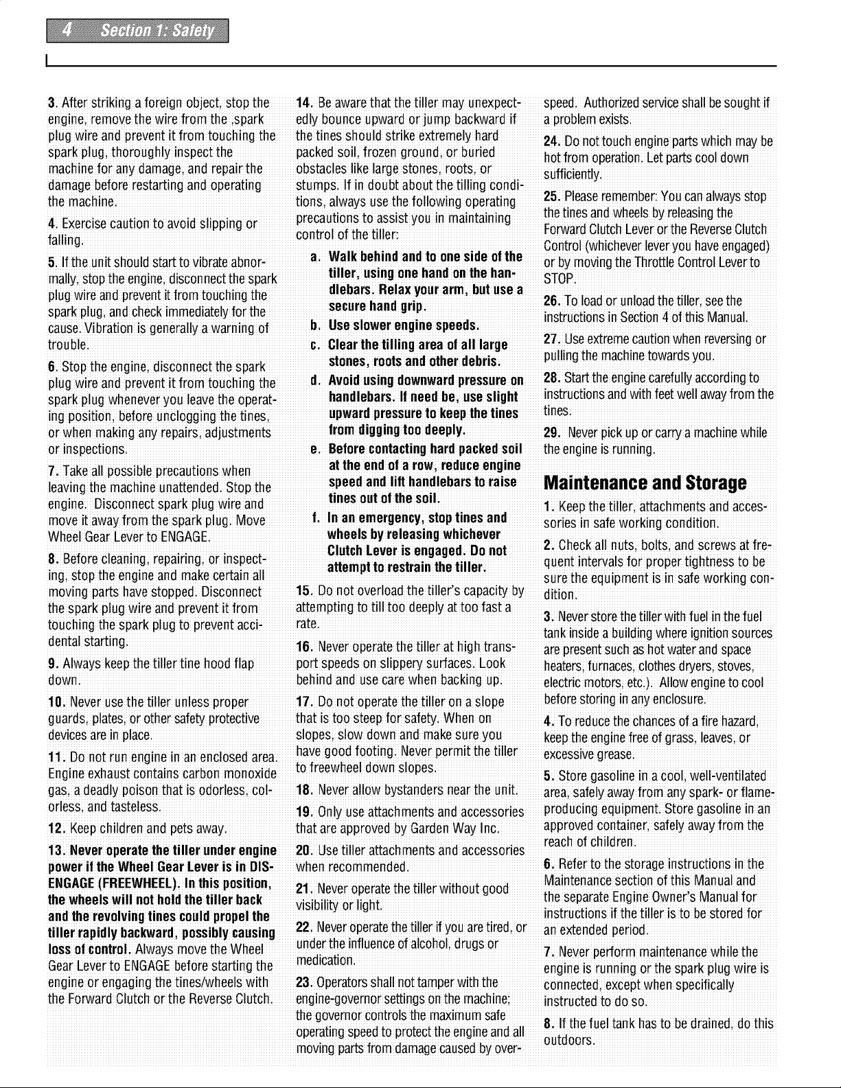
Safety Decals
For your safety and the safe_ of others, Keep the decals €lean and legible at all Refer to the Parts List in thisman ual for
various safetyand operationaldecalsare times. Contactyour local Servicedealeror decalIocations, partnumbers and order-
located on your unit (see Figure1-2 thefactop¢for replacementsif any decals ing instructions
below)i aredamagedor missing:
Con#ol Descriptions
TineWarning(on controlPanel)
(onright side of
hoodflap)
Message(on engine)
(ontine hood)
Belts
Warning(on belt cover)
Figure1,2: LocationofSafetyand OperatingDecals
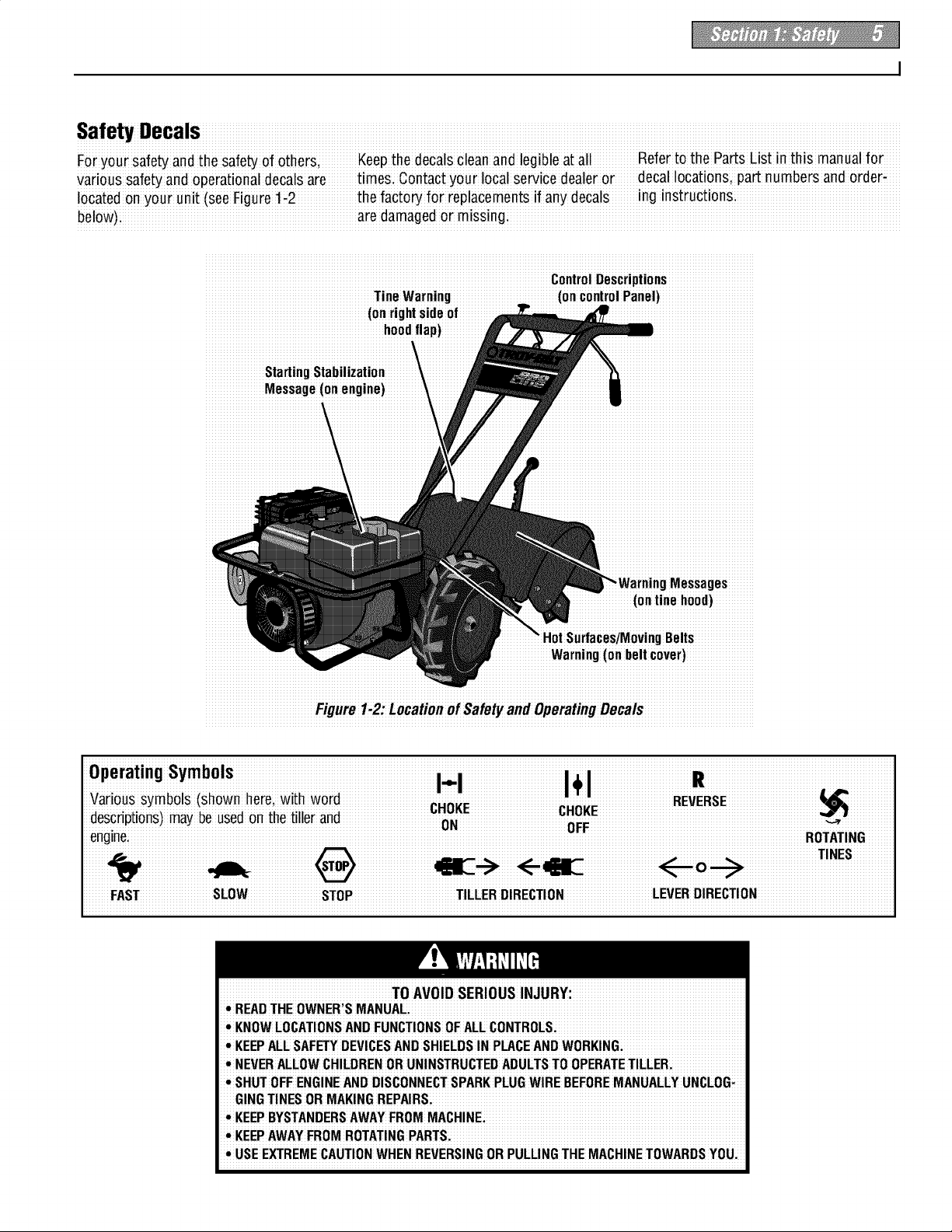
FAST SLOW STOP TILLERDIRECTION LEVERDIRECTION
TO AVOID SERIOUS INJURY:
• READTHE OWNER'SMANUAL
• KNOWLOCATIONSAND FUNCTIONSOFALL CONTROLS:
• KEEPALLSAF_Y DEVICESANDSHIELDSIN PLACEANDWORKING:
• NEVERALLOWCHILDRENOR UNINSTRUCTEDADULTSTOOPERATETILLER.
!•SHUTOFF ENGINEANDDISCONNECTSPARKPLUGWIRE BEFOREMANUALLYUNCLOG_
GING TINESOR MAKINGREPAIRS:
• KEEPBYSTANDERSAWAYFROMMACHINE:
• KEEPAWAYFROM ROTATINGPARTS.
!• USEEXTREMECAUTIONWHENREVERSINGOR PULLINGTHE MACHINETOWARDSYOU;
To prevent personal injury or property
damagei do notstart the engine until aII
assembly steps are complete and you
haveread andunderstandthe safetyand
operatinginstructionsinthis Manual:
INTRODUCTION
Carefullyfollow theseassembly steps to
correctly prepareyour tiller for use. It is
recommendedthat you readthis Section
in itsentirety beforebeginning assembly.
INSPECTUNIT
Inspect the unit andcartonfor damage
immediately after delivery. Contactthe
carrier (trucking company) if you find or
suspect damage. Inform them of the
damageand request instructions for filing
a claim. To protect your rights, put your
claim inwriting and mail a copyto the
carrier within 15 daysafter the unit has
beendelivered. Contactus at the factory if
you needassistanceinthis matter.
UNPACKINGANDASSEMBLY
INSTRUCTIONS
STEP 1: UNPACKING INSTRUCTIONS
1. Removeanycardboard inserts and
packaging materialfrom the carton.
Removeany staplesfrom the bottom of
the carton and removethe carton.
2. Cutthe large,plastictie strap that
securesthe transmission tube to the ship-
ping pallet. Leavethe handlebarson top of
the tiller to avoid damaginganycables.
3. A bagwith loosehardwareis insidethe
literature envelope. Checkthe contents
againstthe following list and Figure2-1.
Contactyour localdealerorthe factory if
anyitemsare missing or damaged.
NOTE: Forelectric start units, a second
hardwarebag is located nearthe battery.
4. The tiller is heavy. You should not
attempt to remove itfrom the shipping
platform until instructed to do so in these
"Assembly" steps.
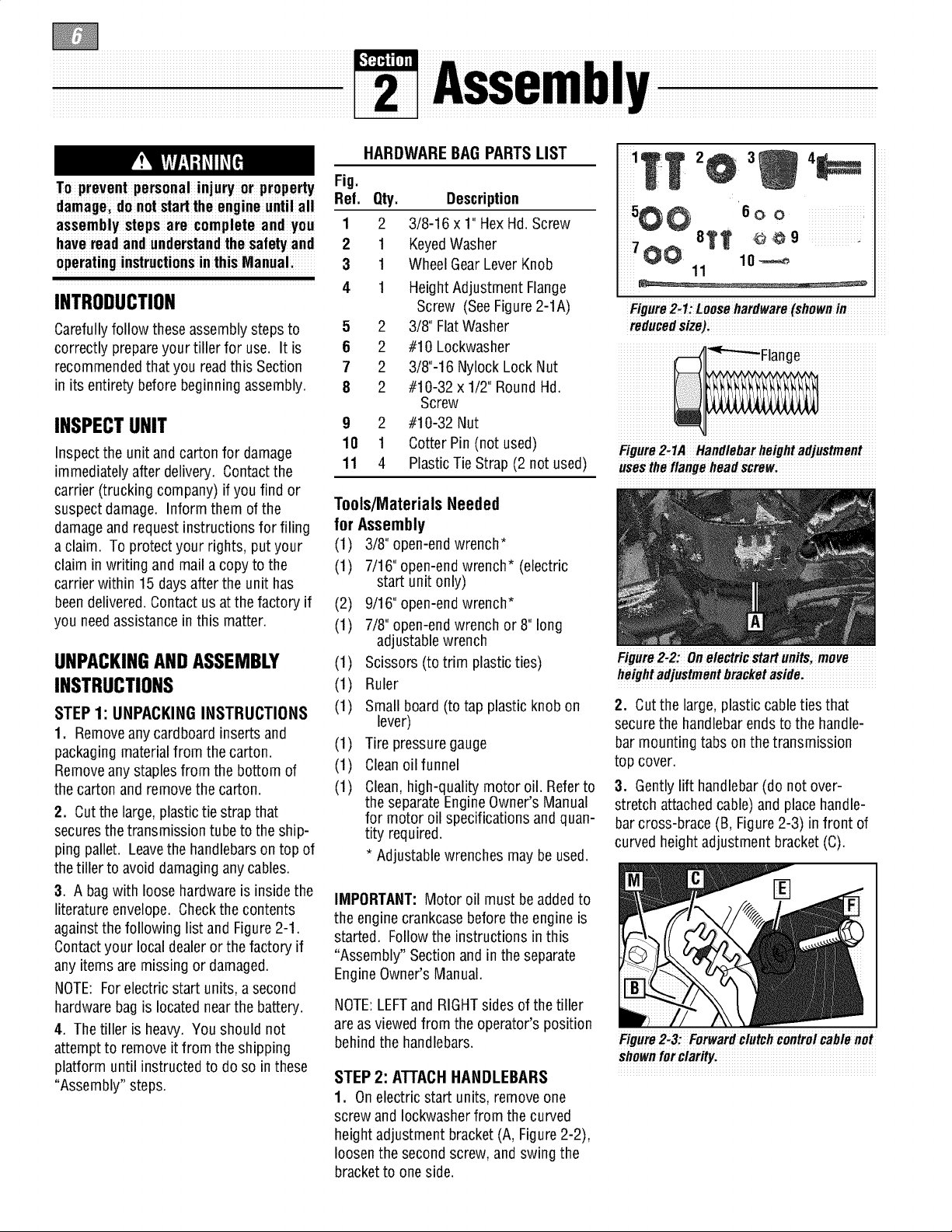
HARDWARE BAG PARTS LIST
Fig.
Ref. Qty. Description
1 2 3/8-16 x 1"HexHd.Screw
2 1 KeyedWasher
3 1 WheelGearLever Knob
4 1 HeightAdjustment Flange
Screw (SeeFigure2-1A)
5 2 3/8" FlatWasher
6 2 #10 Lockwasher
7 2 3/8"-16 Nylock Lock Nut
8 2 #10-32 x 1/2" RoundHd.
Screw
9 2 #10-32 Nut
10 1 Cotter Pin (not used)
11 4 Plastic Tie Strap (2 not used)
Tools/Materials Needed
for Assembly
(1) 3/8" open-end wrench*
(1) 7/16" open-end wrench* (electric
start unit only)
(2) 9/16" open-endwrench*
(1) 7/8" open-end wrench or 8" long
adjustablewrench
(1) Scissors (to trim plasticties)
(1) Ruler
(1) Small board (to tap plastic knob on
lever)
(1) Tire pressuregauge
(1) Cleanoilfunnel
(1) Clean,high-quality motor oil. Referto
the separateEngineOwner's Manual
for motor oil specifications and quan-
tity required.
* Adjustablewrenches maybe used.
IMPORTANT:Motor oil must beaddedto
the engine crankcasebefore the engine is
started. Followthe instructions in this
"Assembly" Sectionand in theseparate
EngineOwner's Manual.
NOTE:LEFTandRIGHTsides ofthe tiller
areasviewed from the operator's position
behind the handlebars.
STEP2: ATTACHHANDLEBARS
1. Onelectric start units, removeone
screwand Iockwasherfrom the curved
heightadjustment bracket (A, Figure2-2),
loosenthe secondscrew,andswing the
bracketto oneside.
4_
_iiiiiiiiiiiiiii_ iii
11
iiiiii iii
Figure2-1:Loosehardware(shownin
reducedsize):
Figure2,1A Handlebarheightadjustment
usestheflange headscrewi
Figure2:2:0n electric start unitsi move
height adjustmentbracket aside:
2. Cut the large,plastic cableties that
securethe handlebar ends to the handle-
bar mounting tabs onthe transmission
top cover.
3. Gently lift handlebar(do not over-
stretch attachedcable) andplace handle-
bar cross-brace (B, Figure2-3) infront of
curved height adjustment bracket(C).
Figure2.3: Forwardclutchcontroicable not
shownforclarity.
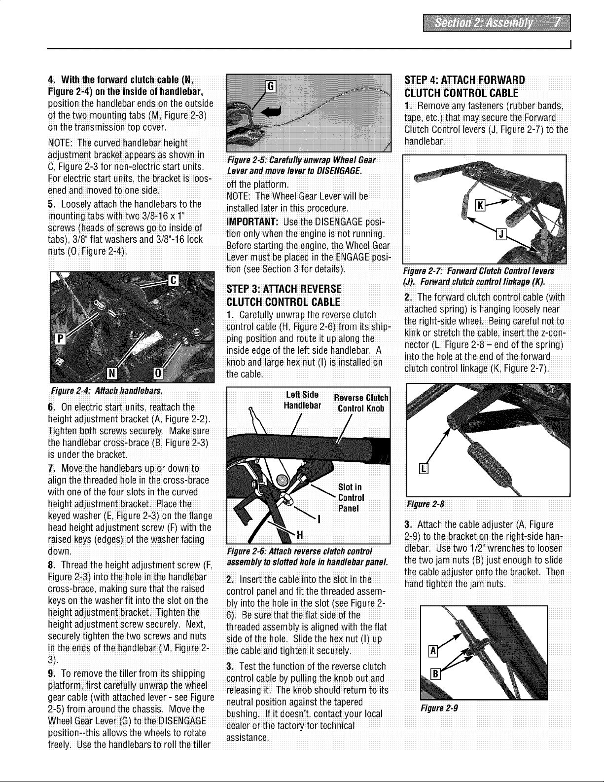
4: Withtheforwardclutchcable(N,
Figure2-4)on the insideofhandlebar,
position the handlebarends onthe outside
ofthe two mounting tabs (M, Figure2-3)
onthe transmission top covc
NOTE:The curved handlebar height
adjustment bracketappearsasshown In Fi..ure2 5: Carefull;unwra"Wheel r
....... _.............................................. ..................... ;................. y _ , y p U_a: ..................
C; Figure2i3 for non-electric start un!tSl_everan #moveleverto
Forelectric stag units, the bracket is Ioos-of f the la_oim _
ened and movedto oneside P
' NOTE:The WheelGearLeverwill be
handlebari
5i Loosely attach the handlebarsto the installed later inins p¢oceduie I
mounting tabs with two 3/8#16×1 1 I
screws (headsof screwsgoto Inside of : ....
_,_ ._0ii_1_ _,_._ _ only when the engineis riot running
tau_.l;,_/o mw<_s,ers<_nao/o!, v,OuK'
,. _i_;;_ ,, Before starting theengine; theWheelGear
i : IMPORTANT' Usethe DISENGAGEposi.
,uL_!ui rluu_ 5i_!' Levermust be placedin the ENGAGEposii
tion (seeSection 3 for details). Figure2;7:FetwardClMcfl Controllevers
CLIITCH CONTROLCABLE 2: Theforward clUtChcontrol cable(with
STEP4: ATTACH FORWARD
CLUTCH CONTROL CABLE
1: Removeany fasteners (rubber bands;
tape, etci) that maysecurethe Forward
ClutchControl levers (JiFigure2-7)to the
control cable(H,F gure2:6)from its Sh i22 _ _i_.2_22_ _2,1 ,u :_
ping posll:lOnano rou[e i[ upalong [ne x,x..x; r=xi;, _o _ _.__., xx;i
', ;_ kink or s[reLcnthecal_,eiinset[ [l]e z-con-
inslde edgeof the left slde handlebar: A :: :_ ;
isinstalled on 'n[° me no,eal:me eno
the cable, Je(Ki Figuie2i 7)
Left Side ReverseClutch
61 Onelectric start units, reattachthe
Handlebar ControlKnob
heightadjustment bracket (A; Figure2-2)
Tighten bothscrews securelyi Makesure
the handlebarcross-brace (B; Figure2-3)
isunder the bracket.
7: Movethe handlebars u) or downto
align the threadedhole inthe cross-brace
with oneof the four slots in the curved
heightadjustment bracket: Placethe
Slotin
Control
Figure2,8
keyedwasher (E Figure2-3)onthe flange
headheightadjustment screw (F)with the 3; Attachthe cableadjuster (A; Figure
raisedkeys (edges)of thewasher facing 2-9)to the bracketonthe right-side han-
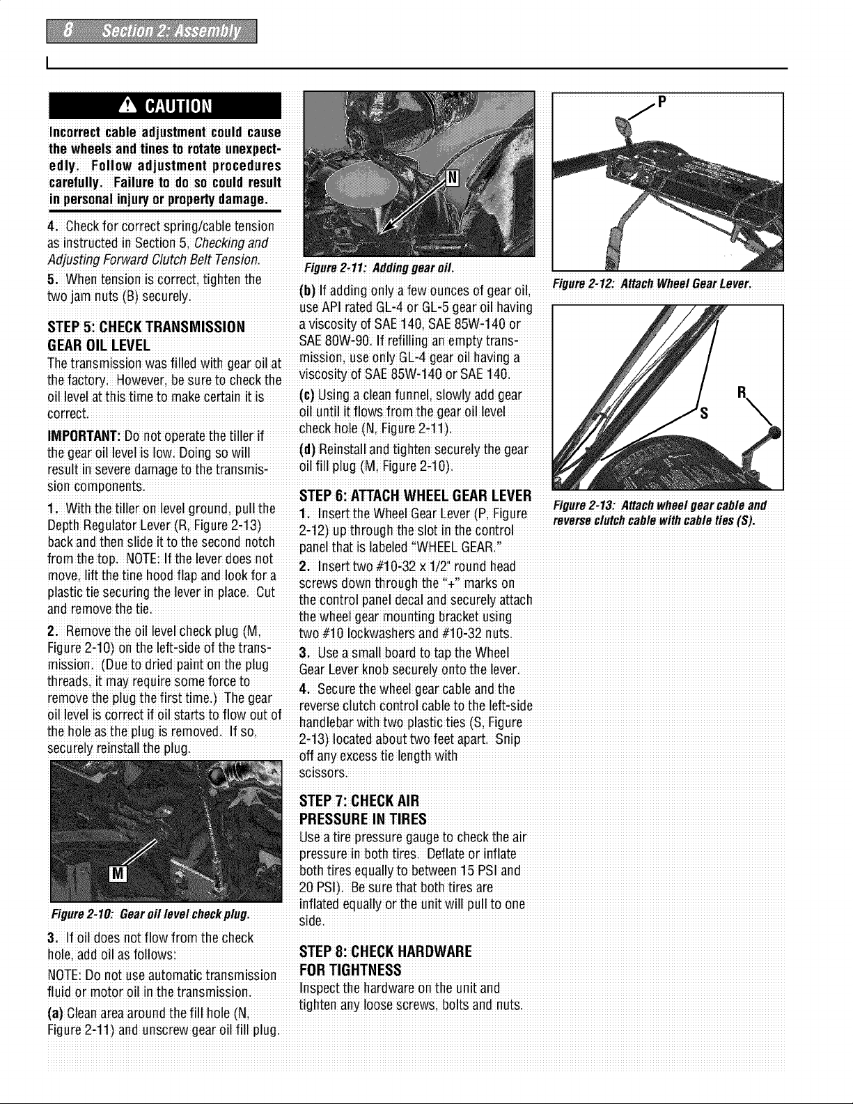
downi Figure2,6:Attach reverseclutch control !n
Thi._ih _h_inhi _rli,mtm_ni _r_w i assemblytoslottedholeinhandlebar the two jam nuts (B}jast enough to slid
Fiour'e2"3: i_o _ hole'_nthe hand eba'r' the Cableadjusteronto the bracket: Then
g-) 2i Insert the cable intothe slot in the handti, htenthe iam nuts
crossfbrace; making suie !hat !he raised coniiol paneland fii the threadedassemi
keysonthe washerfit into theslot onthe bly into the holeinthe slot (seeFigure2-
heightadjustment bracketi Tightenthe 6)Be surethat the flat side ofthe
heightadjustment screw securely. Nexti threadedassembly is aligned with theflat
securelytighten thetwo screws andnuts side of the holei Slidethe hexnut (I)up
in theends of the handlebar(Mi Figure2- the cableand tighten it securely
3)
9 To removethe tiller from its shipp ng
pla_ormi first carefully unwrap the wheel il in it TI_ h I r t rnt it
gear cable(wzth attachedlever, see Rgure :i : r
2:5) from aroundthe chassis Movethe :. Figure 2_9
_,,7 ;" _.Z_C2_.._ bushingi If It doesnt, contactyour local
wnee bear Lever_Ll_:omeu_l:i'_L1ALll: ir it h f t f r t hni I
.;idea e o e ac o_ o ec ca
...... eeas g. e obs cud eu o s
...... ...... .... neutralpositon againstthe tape ed .................................................................................
control cable bypulhngthe knob out and
pos!t!oni4h!s allowsthe wheels to rotate assistance'
freely;Use thehandlebars to roll the tiller
Incorrect cable adjustmentcouId cause
the wheels andtines to rotate unexpect-
edlyi Follow adjustment procedures
carefullyi Failure to do so could result
in personalinlu_ or prope_ damage.
4 Checkfor correct spring/cable tension
aSinstructedinSection5;Checkingand
Adjusting ForwardClutchBelt Tension. ,,, ..., __ ,,_,,, .,,, ,.,
..
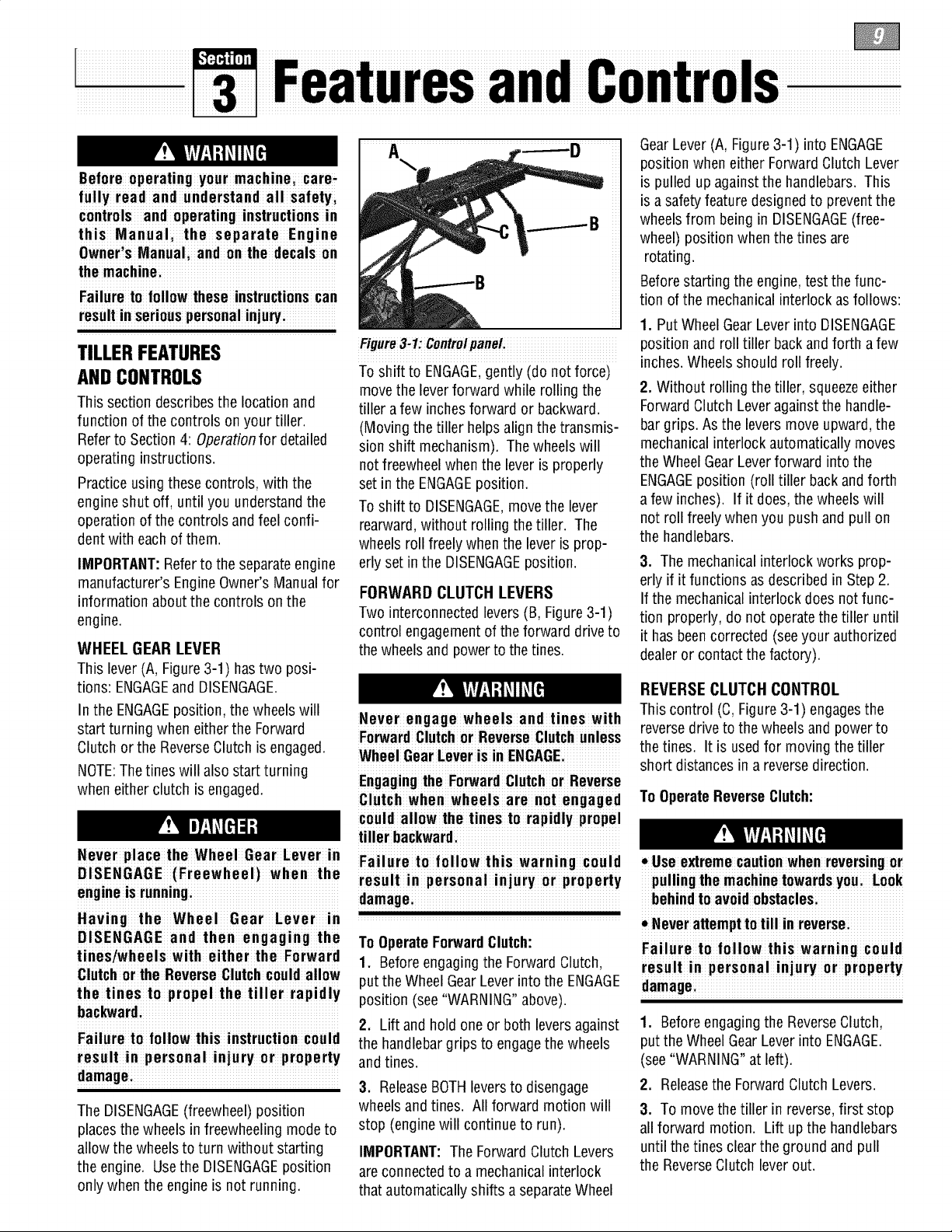
5. Whentension is correct; tighten the Figure2.12: AttachWfleei Gear Lever
two iam nuts (B_securely (b)If adding only a few ounces of gearoil
_ uSeAP iaied GLi4 oi GEi5geai oil havng
STEP 5: CHECKTRANSMISSION a viscosity of SAE 140;SAE85W,140or
• : mission useonly GL,4gear oil having a...........
Thetransmiss!on was f!lled w!th gearo!lat. i., k,; _;:
the factoryi However;besure to checkthe-
VISOOSll:yOf hAL UbVV14U or bat: ]qU
oil levelatth istime to makecertainit is (c)Usi ngacleanfunnel; slowly add gear R
correct, oil until it flows from the gearoil level i
IMPORTANTiDo noi oieraie i heiiller if checkh ole(N, Figure 2-11)
the gear oil levelis Iowi going so will (d) Reinstalland tighten securelythegear
iesuli in seveie damageto thetransmisi oilfill plug (Mi Figure2-1 O)
sloncomponents.
1 With the tiller o e egou d;pu '
DepthRegulatorLe (R, F!gu e 2,12)up through the slot !n thecontrol
n I v I r n Ilth Figure2 13 Attachwheelgear cable and
v r " r utchcablewlthcab eties(S).
backand then slide it to the second notch .....
.fromthe mp NOTP If the roverdoes _i_ _C _}_i _X,_
:1 ..' i'. Insert two#_U-o/x UZ round Ilead
move, h.fttne tlne hOOdflap ano lOOK.foraii _..#X
plastictlesecurlngtheeverlnplac Cut th cntil ne I nd e reI tt h
_:.:.'e _o o pa e _aa scu ya ac
i screwsdown through the irl_o M,,
STEP6: ATTACHWHEEL GEARLEVER
1, Insert the WheelGearLever(Pi Figure i . i .
: panel that is labeled WHEELGEA&
and removeme _mi ihe wheel geai mouniing biacket using
2i Removethe oil levelCheckplug (M; two #t0 Iockwashersand #10:32 nutS:
Figure2-10)on the left-side of thetrans-3 Used small board to tad theWheel
mission. (Dueio dried paint onihe plug Gear Leverknobsecurely onto the levei.
threads itmay require some forceto
..... ...... 4 Secure the wheelgearcable and the
removethe plug the first time )The gear
: :i reverseclutch control cableto the left-side
011level is correc[ i.f Oll sEar[s £o TIOWOU£01" ;.-
_i; _ ,._; _i;_ nanaleoarWl1:nl:woplasl:lCl:les i-igure
then°iea_tu_piuui_'em°veu "Su' 2 1 Itd ottw let _
securelyreinstall the plug
. ' -3) ocaeab u o eapa 4S p
' offany excesstie length with
SClSSOrS_
STEP7: CHECKAIR
PRESSUREIN TIRES
Useatire pressuregauge to check theair
pressurein bothtire& Deflateor inflate
bothtires equally to between15PSI and
20 PSI)i Be surethat bothtires are
,,,inflated equally or the unit will pull to one
I-#gurez-Tu: _earo# mve#cnecKpmgi sidei
3; If oil doesnot flow from the check
fluid or motor oil inthe transmissioni Inspect the hardwareon the unit and
Li _'_ _ _i _ ;_ _iiiL_i_ tighten any loose Screws;bolts and nuts
(a] umanareaaround _nefin Ilo_e tin,
Figure2,11)and unscrew gear Oilfill plug:
Before operating your machinei care,
fully read and understand all safetyi
controls and operating instructions in
this Manual, the separate Engine
Owner,sManuali and on the decals on
the machinei
Failureto follow these instructionscan
resultin seriouspersonalinjury,
TILLERFEATURES
ANDCONTROLS
This section describesthe location and
function of the controls on your tiller.
Referto Section4: Operationfor detailed
operating instructions.
Practiceusing thesecontrols, withthe
engine shut off, until you understandthe
operation of the controls and feelconfi-
dentwith eachof them.
IMPORTANT:Referto the separateengine
manufacturer's EngineOwner's Manualfor
information aboutthe controls on the
engine.
WHEEL GEAR LEVER
This lever(A, Figure3-1) hastwo posi-
tions: ENGAGEand DISENGAGE.
In the ENGAGEposition, the wheels will
start turning when either the Forward
Clutchor the ReverseClutch is engaged.
NOTE:Thetines will alsostart turning
when either clutch isengaged.
Never place the Wheel Gear Lever in F il r I II w hi w rnin I
DISENGAGE (Freewheel) when the
engme is running, damage
Having the Wheel Gear Lever in
DISENGAGE and then engaging the
tines/whe els with eithe r the Forward
Clutchor the ReverseCIutchcouId allow
the tines to propel the tiller rapidly
hac_ard:
Failure to follow thisi nstruction couId
result in personal injury or property
damagei
The DISENGAGE(freewheel) position
placesthe wheels in freewheeling mode to
allow the wheelsto turn without starting
the engine. Usethe DISENGAGEposition
only when the engine is not running.
Figure3-1:ControipaneL
To shift to ENGAGE,gently (do not force)
movethe leverforward while rolling the
tiller a few inchesforward or backward.
(Moving the tiller helps align the transmis-
sion shift mechanism). Thewheelswill
notfreewheel when the leveris properly
set inthe ENGAGEposition.
To shift to DISENGAGE,movethe lever
rearward,without rolling thetiller. The
wheels roll freelywhen the lever is prop-
erly set in the DISENGAGEposition.
FORWARD CLUTCH LEVERS
Two interconnectedlevers(B, Figure3-1)
control engagementof the forward drive to
the wheelsand power to the tines.
Never engage wheels and tines with
ForwardClutchor Reverse Clutchunless
Wheel Gear Leveris in ENGAGE:
Engagingthe Forward CIutch or Reverse
Clutch when wheelsarenotengaged
could allow the tines to rapidly propel
tiller backward.
a u eto o o t s a gcou d
result in personal injury or property
!
To OperateForwardClutch:
1. Before engagingthe Forward Clutch,
putthe Wheel GearLever intothe ENGAGE
position (see"WARNING"above).
2. Lift andhold oneor both leversagainst
the handlebargrips to engagethe wheels
and tines.
3. ReleaseBOTHleversto disengage
wheels and tines. All forward motion will
stop (enginewill continue to run).
IMPORTANT:The Forward Clutch Levers
are connectedto a mechanicalinterlock
that automaticallyshifts a separateWheel
GearLever(A, Figure3-1) into ENGAGE
position when either ForwardClutch Lever
is pulled up against the handlebars. This
isa safety feature designedto prevent the
wheelsfrom being in DISENGAGE(free-
wheel) position whenthe tines are
rotating.
Beforestarting the engine,test the func-
tion ofthe mechanicalinterlock asfollows:
1. Put WheelGearLeverinto DISENGAGE
position and roll tiller backandforth a few
inches.Wheelsshould roll freely.
2. Without rolling the tiller, squeezeeither
ForwardClutch Leveragainst the handle-
bargrips. Asthe levers move upward, the
mechanicalinterlock automatically moves
the Wheel GearLeverforward into the
ENGAGEposition (roll tiller back andforth
a few inches). If it does, the wheelswill
not roll freely whenyou pushand pull on
the handlebars.
3. The mechanicalinterlock works prop-
erly if it functions as describedin Step 2.
If the mechanical interlock does notfunc-
tion properly, do not operate thetiller until
it has beencorrected (seeyour authorized
dealer or contact the factory).
REVERSECLUTCH CONTROL
This control (C, Figure3-1) engagesthe
reversedriveto the wheels and power to
the tines. It is used for moving the tiller
short distancesin areversedirection.
To OperateReverseClutch:
• Use extremecautionwhen reversingor
pulling the machinetowardsyou Look
behindto avoidobstaclesi
• Neverattemptto till in reversei
Failure to follow this warning could
result in personal injury or property
damagei
1. Beforeengaging the ReverseClutch,
putthe WheelGearLeverinto ENGAGE.
(see"WARNING"at left).
2. Releasethe ForwardClutch Levers.
3. To movethetiller in reverse,first stop
all forward motion. Lift up the handlebars
until the tines clearthe ground and pull
the ReverseClutch lever out.
Thewheelswillrotateinareversedirec-
tionaslongastheleverisheldin
REVERSE.Tostopthewheelsandtines,
releasetheleveranditwillreturnto
NEUTRAL.Neverattemptto till while
movingin reversedirection.
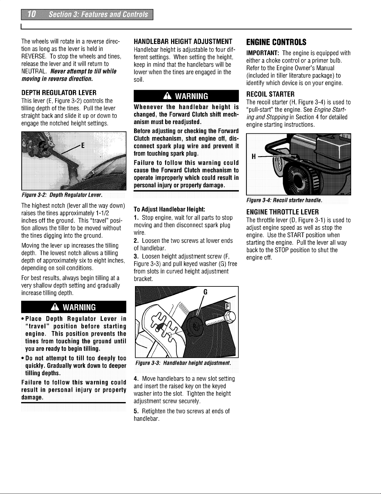
DEPTH REGULATOR LEVER
This lever (E, Figure3-2) controls the
tilling depth of thetines. Pull the lever
straight backand slide it upor down to
engagethe notched heightsettings.
Figure3-2: Depth RegulatorLever:
Thehighest notch (lever allthe waydown)
raisesthe tines approximately 1-1/2
inches off the ground. This "travel" posi-
tion allows the tiller to be moved without
thetines digging into the ground.
Moving the leverup increasesthetilling
depth. The lowest notchallows atilling
depth of approximatelysixto eight inches,
depending on soil conditions.
Forbest results, alwaysbegintilling at a
very shallow depthsetting andgradually
increasetilling depth.
HANDLEBAR HEIGHT ADJUSTMENT
Handlebarheight is adjustableto four dif-
ferent settings. When setting the height,
keepin mind that the handlebarswill be
lower when the tines are engagedinthe
soil.
Whenever the handlebar height is
changed,the ForwardClutchshift mech,
anismmustbe readjusted:
Beforeadjustingor checkingthe Forward
Clutchmechanismi shut engine oil dis,
connectspark plug wire and prevent it
fromtouchingsparkplug:
Failureto follow this warning could
causethe ForwardClutchmechanismto
operateimproperlywhich could result in
personalinjuryor prope_y damagei
To AdjustHandlebarHeight:
1. Stop engine,wait for all parts to stop
moving and then disconnect spark plug
wire.
2. Loosen the two screws at lower ends
of handlebar.
3. Loosen heightadjustment screw (F,
Figure3-3) and pull keyedwasher (G) free
from slots incurved heightadjustment
bracket.
G
ENGINECONTROLS
IMPORTANT:The engine is equippedwith
either a choke control or a primer bulb.
Referto the EngineOwner's Manual
(included intiller literature package)to
identifywhich deviceison your engine.
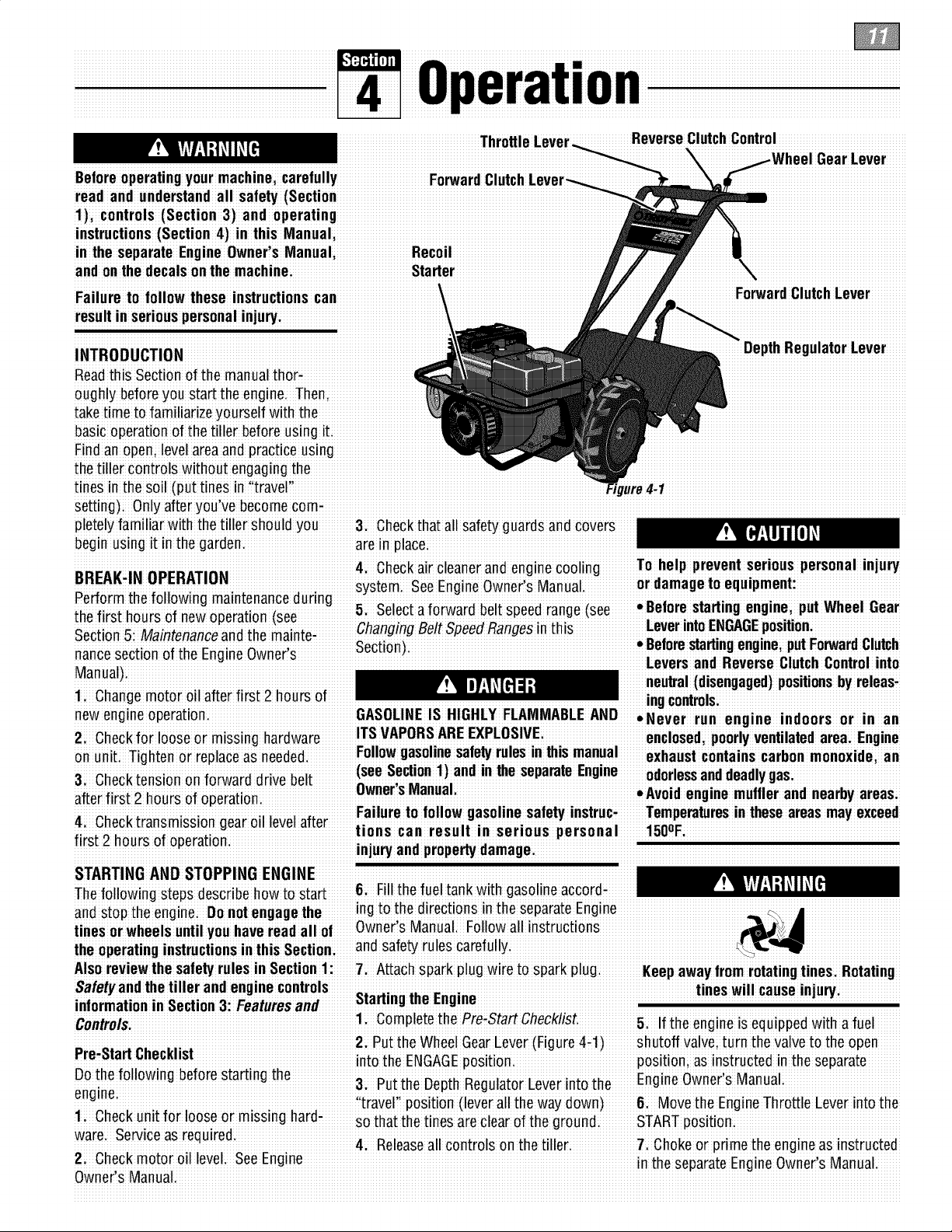
RECOIL STARTER
The recoil starter (H, Figure3-4) is usedto
"pull-start" the engine. SeeEngineStart-
ing and Stopping in Section 4 for detailed
engine starting instructions.
Figure3_4:Recoilstarterhandle:
ENGINETHROTTLE LEVER
Thethrottle lever(D, Figure 3-1) is usedto
adjust enginespeedaswell as stopthe
engine. Usethe STARTposition when
starting the engine. Pullthe leverall way
backto the STOPposition to shut the
engine off.
• Place Depth Regulator Lever in
iltraveli' position before starting
enginei This position prevents the
tines from touching the ground until
youare readyto begintilling;
• Do not attempt to tilltoo deeplytoo
quicklyi Graduallywork downto deeper
tilling depthsi
Failureto follow this warning could
result in personal injury or property
damagei
Figure3_3!Handlebarheightadjustment!
4. Move handlebars to a newslot setting
and insert the raised keyonthe keyed
washer into the slot. Tighten the height
adjustment screw securely.
5. Retighten thetwo screws at endsof
handlebar.
Beforeoperatingyour machinei carefull!
read and understandalI safety (Section
1), controls(Sect ion 3) and operating
instructions (Section 4) in this Manual
in the separate EngineOwner's Manual Recoil
and onthedecalson the machine: Starter
Failure to follow these instructionscan
resuIt in seriouspersonalin]ury
Thr
ReverseClutchControl
INTRODUCTION
DepthRegulatorLever
Readthis Section ofthe manualthor
oughlybefore you start the engine. Then,
take time to familiarizeyourself with the _
basic o Fit
Findan open; levelarea and practiceusing
thetiller controls withoutengagingthe
tines inthe soil (put tines in "traver' FJ ,re4.1
Setting)i Onlyafter'you've becomecom-
pletely uardSand covers
begin using it in the garden, are m place
.r,r_,s i...r..-,-,.. 4i Checkair cleanei andenginecooling To help prevent serious personalinju_
Dnz:MA-II_ urEn_llu. System. SeeEngineOwner's Manual. or damagetoequipment:
venorm 1:neTonowmgmalm:enanceeunn0 _. Belore startin" endne "ut Wheel Gear
th_ first hm,r_ _f n_w _,r_ti_n (_, _; _e!ec_a xorwaroDe!_speeorange _see u u
Secti_5_Maintenanceandt'he mai'niei ChangingBelt SpeedRangesinthis. _e_erintoE:GAGEiP_sitionFrw r :1 ih
noncesection ofihe Engine Owneris Secti°n) L:[,°erresSZanr__eev_U_c_°C_rt_o_ ui_Cto
Manual)
i neutral(disengaged)positionsby releasi
STARTING AND STOPPING ENGINE
the operatinginstructionsinthis Section: and safetyrules carefully
Control&li Oomple!e!he PreiStartChecklist. 5: If the engine isequipped with a fuel
:::: 2:Put the WheelGearLever (Figure4-1)shutoff Valve;turnthe valve to the open
re,atan L;neCKB_SZ nto the ENGAGEposit oni positioni as instructed in theseparate
eDn°4hnef° I°win! bef°re star!ing !he & Put the Depih RegulatoiEeverinto the EngineOwnerls Manua
'iiiavelii position (leveiall the way downi 6. Moveihe EngineThiottle Eeveiinto the
1 Checkunit for looseor missing hardi Sothat thetinesareclear of the groundi STARTposition:
ware. Service as r.equired. 4. Releaseall conirols on ihe tillei 7. Chokeoi prime ihe engine as instiucted
2 Checkmotor oll level SeeEngme Rnth rt En in wn r' M n I
...... ...... esepaia!e! igiieO ie s !aiaa!.
Owner'sManual.
 Loading...