

Troybilt 21A-634F063, 21A-634B063, 21A-630C063 Owner’s Manual
O TRO_ BILT
Operator's Manual
Rear-tine Tiller Models
630C Tuffy_
634Fm BroncoTM
634Bm Super BroncoTM
Model 634B Shown
IMPORTANT: READ SAFETY RULES AND INSTRUCTIONS CAREFULLY
WARNING: This unit is equipped with an internal combustion engine and should not be used on or near any unimproved forest-
covered, brush-covered or grass-covered land unless the engine's exhaust system is equipped with a spark arrester meeting applicable
local or state laws (if any). If a spark arrester is used, it should be maintained in effective working order by the operator. In the State of
California the above is required by law (Section 4442 of the California Public Resources Code). Other states may have similar laws.
Federal laws apply on federal lands. A spark arrester for the muffler is available through your nearest engine authorized service dealer or
contact the service department, P.O. Box 361131 Cleveland, Ohio 44136-0019.
TROY-BILT LLC, P.O. BOX 361131 CLEVELAND, OHIO 44136-0019
PRINTEDINU.S.A. FORM NO. 770-10594C
11/25/02
TABLEOFCONTENTS
Content Page
CallingCustomerSupport.......................................................................................................2
Safety......................................................................................................................................3
Assembly................................................................................................................................6
FreaturesandControls............................................................................................................lg
Operation................................................................................................................................12
Maintenance...........................................................................................................................17
Off-SeasonStorage.................................................................................................................21
Troubleshooting......................................................................................................................22
Parts List ................................................................................................................................23
WarrantyInformation..............................................................................................................BackCover
FINDINGMODELNUMBER
This Operator'sManualisan important partof your newRear-tineTiller. It will helpyouassemble, prepareandmaintain the unit for
best performance. Pleasereadand understandwhat it says.
information from itinthespace providedbelow.This information isvery importantif you needhelpfrom our Customer
Beforeyoustart assemblingyour new equipment,pleaselocatethe modelplateon the equipment andcopy the
Support Departmentor an authorizeddealer.
You can locatethe model number by lookingon the rearsurfaceof thetine shield.A sample model plate is explainedbelow. For
future reference,pleasecopy the modelnumber andtheserial numberof the equipment inthe spacebelow.
Copythe model numberhere:
Copythe serial numberhere:
O TRII_BILT • _."__-_ _. _
www.troybilt.com CLEVELAND,OH44136
• 866-840-648_
330-558-7220
ENGINEINFORMATION
Theengine manufacturer is responsiblefor allengine-relatedissueswith regardto performance,power-rating, specifications,
warrantyand service. Pleasereferto the enginemanufacturer's Owner's/Operator'sManualpackedseparatelywith your unitfor more
information.
CALLINGCUSTOMERSUPPORT
If you havedifficulty assemblingthis product or haveanyquestionsregarding thecontrols, operationor maintenanceofthis unit,
pleasecall the CustomerSupport Department.
Call1- (330) 558-7228 or 1- (866) 848-6483to reacha Customer Support representative.Pleasehaveyour unit's
model numberandserial number readywhen you call.Seeprevioussection to locatethis information. You will be
askedto enterthe serial
SECTION1: SAFETY
Thismachinemeetsvoluntarysafetystan-
dardB71.8-1996, whichissponsoredbythe
OutdoorPowerEquipmentInstitute,Inc.,
andis publishedbythe AmericanNational
StandardsInstitute.
WARNING
The engine exhaust from this productcontains
chemicals known to the State ofCalifornia to
cause cancer, birth defects or other reproduc-
SafetyAlertSymbol
in this manual and on the unit to alert
This is a safety alert symbol. Itis used
you to potential hazards. When you
see this symbol, read and obey the
message that follows it. Failu re to obey
safety messages could result in
persona t injury or property damage.
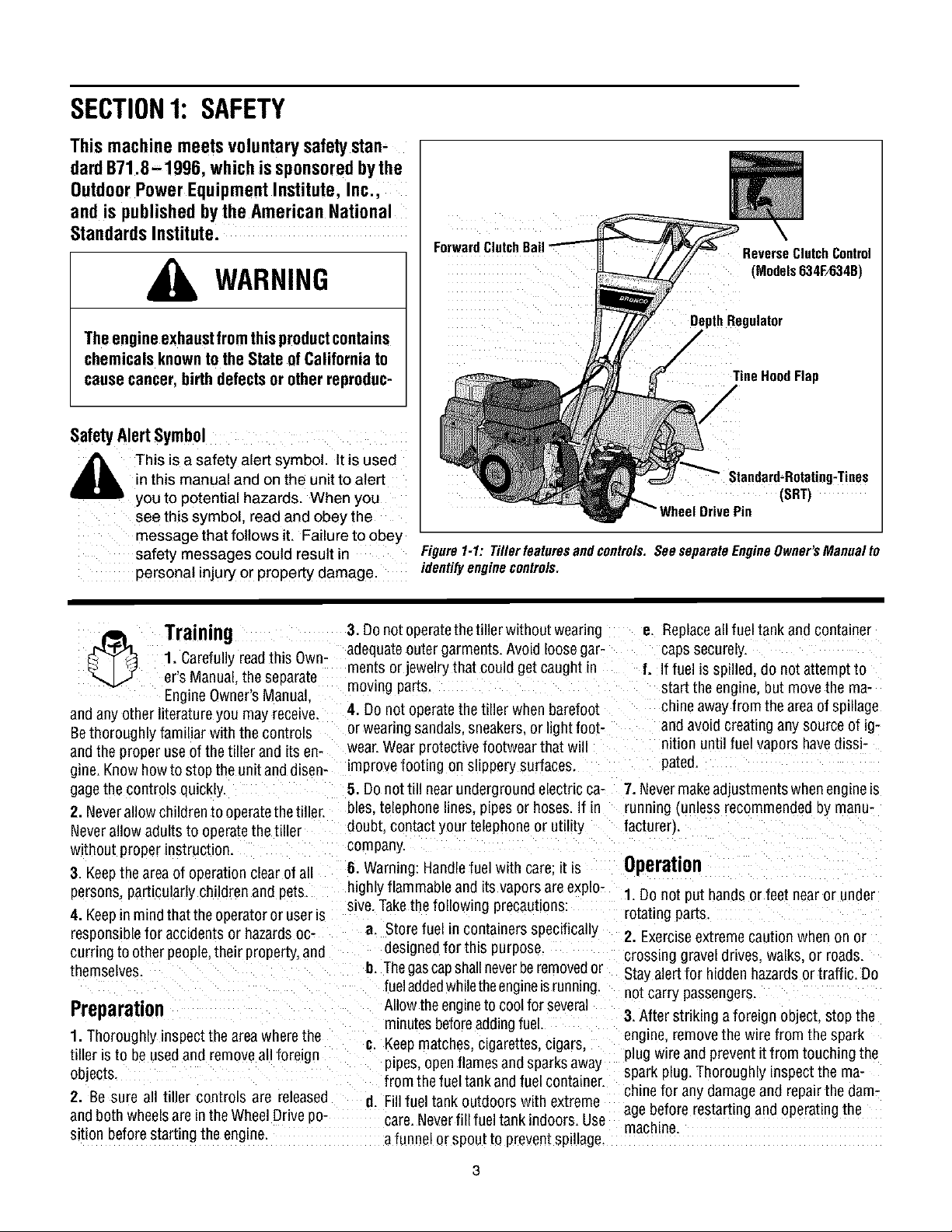
ForwardClutchB_
DepthRegulator
ReverseClutchControl
(Models634F/634B)
TineHoodFlap
/
(SRT)
Figure1-1:Tillerfeaturesandcontrols.SeeseparateEngineOwner'sManualto
identifyenginecontrols.
3. Donot operatethetiller without wearing
1. Carefullyreadthis Own-
Training
er's Manual.the separate
EngineOwner'sManual
andany other literatureyou may receive.
Bethoroughly familiar withthe controls
andthe proper use of the tiller and its en-
gine.Know howto stop the unitand dlsen- improve footing on slippery surfaces.
gagethe controls quickly.
2. Neverallow children to operatethetiller.
Neverallow adults to operatethe tiller
without proper instruction.
3. Keepthe area of operation clear of all
persons,particularly children and pets
4. Keepin mindthat theoperatoror useris
responsiblefor accidents or hazardsoc-
curring to other people,their property,and
themselves.
Preparation
1.Thoroughly inspectthe areawherethe
tiller isto be usedand removeall foreign
objects.
2. Be sure all tiller controls are released
andboth wheelsare in theWheelDrive po-
sition beforestarting the engine.
adequateouter garments. Avoid loosegar-
ments or jewelry that could get caught in
moving parts.
4. Do not operatethe tiller when barefoot
or wearing sandals,sneakers,or light foot-
wear.Wearprotective footwear that wi
5. Donottill near underground electricca- 7. Nevermakeadjustments when engine_s
bles. telephone lines, pipes or hoses.If in running {unlessrecommended oy manu-
doubt contact your telephoneor utility facturer).
company.
6. Warning: Handlefuel with care: it is Operation
highly flammableand its vaporsare explo-
sive.Takethe following precautions:
a. Storefuel in containersspecifically
desLgnedfor this 3urpose.
I]. Thegascapshallneverberemovedor
fueladdedwhiletheengineis running.
Allow theengineto coolfor several
m_nutesbeforeaddingfuel.
#. Keepmatches, cigarettes, cigars,
ptpes,openflames and sparksaway
from the fueltank and fuel container.
d. Fillfuel tank outdoors with extreme
care.Neverfill fueltank indoors. Use
a funnel orspou[ to preventspillage.
e. Replaceall fuel tank and container
caps securely.
f. If fuel is spilled, do not attempt to
start the engine, but movethe ma-
chine awayfrom the areaof sp_llage
and avoid creating any source of ig-
lit{on until fuel vapors havedissi-
pated.
1. Do not put hands or feet near or under
rotating parts
2. Exerciseextremecaution when on or
crossing gravel drives, walks, or roads.
Stayalertfor hidden hazardsor traffic. Do
not carry passengers.
3.Nter striking a foreign object, stop the
engine,removethe wire from the spark
plug wire andpreventitfrom touching the
spark plug. Thoroughly inspectthe ma-
chinefor any damageand repairthe dam-
agebefore restarting andoperatingthe
machine.
4. Exercisecautionto avoid slippingor fall- If indoubtaboutthetilling conditions,al- 24. Donot touch engine parts which may
ing.
5. If the unit should start to vibrate aonor-
really,stop the engine,disconnect the
spark plug wire and prevent itfrom touch-
ing the sparkplug,and checkimmediately
for the cause. Vibration is generally a
warning of trouble.
6. Stopthe eng he.disconnectthe spark
plugwire and prevent itfrom touching the
spark plug, whenever you leavethe oper-
atingposition, beforeuncloggingthetines.
or whenmaking any repairs, adjustments
or inspections.
7. Takeall possible precautionswhen leav-
ing the machineunattended. Stop the en-
gine. Disconnectthe spark plug wire and
move it awayfrom thespark plug. Besure
that both wheelsare inthe Wheel Drive po-
sition.
8. Beforecleaning, repairing, or inspect-
ing, stop the engine and makecertain all
mowng parts havestopped. Disconnect
thespark plugwire and prevent itfrom
touching the spark plug to preventacci-
dentalstarting.
9. Theflapon thetine hood must bedown
when operatingthetiller.
tO. Neverusethetiller unless proper
guards, plates, or other safety protective
devicesare in place.
11. Donot run the engineman enclosed
area. Engineexhaust contains careen
monoxide gas. a deadlypoison that is
odorless, colorless, and tasteless.
12. Keepchildren andpetsaway.
13.Neveroperatethetiller underengine wheeldown slopes.
powerif the wheels are in theFreewheel
position.Inthe Freewheelposition, the
wheelswill not holdthe tiller backand the
revolving Linescould propelthetiller rapid-
ly,possibly causingloss of control. Always
engagethe wheels with the wheeldrive
pins in the Wheel Drive position before
starting the engineor engagingthe
tines/wheelswith the Forward ClutchBail
(all models_orthe ReverseClutchcontrol
(Models 634F/634Bonly}.
14. Be aware that the tiller may unex-
pectedlybounceupwardorjumpforward
if the tines shouldstrikeextremelyhard
packedsoil, frozenground,or buriedob-
stacleslike large stones, roots,or
stumps.
waysusethe followingoperatingprecau- behot from operation. Letparts cool down
tionsto assistyou inmaintainingcontrol sufficiently.
ofthe tiller: 25. Pleaseremember:Youcanalwaysstop
a. Walk behindandto oneside of the thetines andwheels by releasingthe For-
tiller, usingonehandonthe handle ward Clutch Bailor on Models 634Fand
barsRelax your arm, but usea 634B the ReverseClutchcontrol. _which-
securehandgrip.
b. Useshallower depthregulator
settings,workinggraduallydeeper
with each pass.
c. Useslowerenginespeeds.
d. Clearthe tilling area of all large
stones,rootsorotherdebris.
e. Avoidusingdownwardpressureon
thehandlebars.If needbe, use
slightupwardpressureto keep the
tines from diggingtoodeeply.
f. Beforecontactinghardpackedsoil
at the end of a row.reduceengine
speedandlift the handlebarsto
raise the tines outof the soil.
g. Inanemergency,stopthetinesand
wheels byreleasingwhichever
clutchcontrolis engaged.Do not
attemptto restrainthetiller.
15. Donot overloadthe tiller's capacityDy
attempting to till too deeplyattoo fast a
rate
16. Neveroperatethe tiller at high trans-
port speeds on hard or slippery surfaces.
Look behindand usecarewhen backing
up
17. Do not operatethetiller ona slopethai
is too steepfor safety.When onslopes,
slow down and makesure you havegood
footing. Never permit the tiller to free-
18. Neverallow bystandersnearthe umt.
19. Onlyuseattachments andaccessories
that areapprovedby the manufacturero1
the tiller.
20. Usetiller attachmentsand accessories
when recommended.
21. Neveroperatethe tiller without good
wsibility orlight.
22. Neveroperatethe tiller if you aretired:
or underthe influence ofalcohol, drugs or
medication.
23. Operatorsshall not tamper with the en-
gine-governor settings onthe machine:
the governor controls the maximum safe
operatingspeedto protectthe engine and
all movingparts from damagecaused by
overspeed. Authorized serviceshall be
sought if a problem exists.
evercontrol isengaged),or by movingthe
_gnitionswitch and/orthrottle control lever
on the engineto "OFF"or "STOP".
26. To load or unloadthe tiller, seethe in-
structions in Section4 of this Manual.
27. Useextreme caution when reversing
or pullingthe machinetowards you.
28. Start the enginecarefullyaccording to
instructionsand with feet well awayfrom
thetines.
29. Neverpickupor carry amachinewhile
theengine is running.
MaintenanceandStorage
1. Keepthe tiller, attachmentsand acces-
sories insafeworking condition.
2. Checkall nuts bolts, andscrews at
ervalsfor proper t_ghtnessto be surethe
equipment is insafeworking condition.
3. Neverstore thetiller with fuel inthefuel
tank insidea building where ignition sourc-
esare presentsuchashotwater andspace
heaters,furnaces, clothesdryers, stoves,
electric motors, etc.L Allow the engineto
cool neforestoring the unit inan'yenclo-
sure.
4. To reducethe chancesof afire hazard.
keepthe enginefree ofgrass, leaves,or ex-
cessivegrease.
5. Storegasolinein a cool. well-ventilated
area,safelyaway from any spark- or
flame-producing equLpment. Store gaso-
line in an approvedcontainer,safelyaway
from the reachof children.
6. Refedto the Maintenancesections of
this Manualand the separateEngineOwn-
er'sManualfor instructions if the unit isto
be stored for an extendedperiod.
7. Neverperform maintenancewhilethe
engineis runmng orthe spark plug wire is
connected,exceptwhen specificahy in-
structed to doso.
8. Ifthefueltankhastobedrained dothis
outdoors.
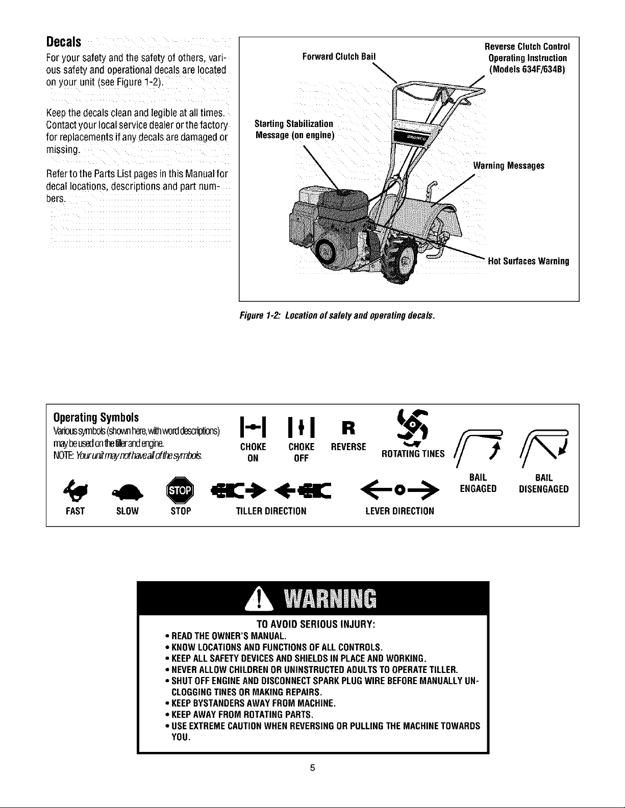
Decals
Foryour safety and the safetyof others, vari-
ous safetyand operationaldecalsare located
on your unit (seeFigure1-2)t
Keepthe decalsclean and legibleat alltimes.
Contactyour localservicedealerorthefactory
for replacementsif any decalsare damagedor
missing.
Referto the PartsList pagesinthis Manualfor
decallocations, descriptions and part num-
bers.
ForwardClutchBail
StartingStabilization
Message(onengine)
Figure1-2:Locationofsafetyandoperatingdecals.
ReverseClutchControl
OperatingInstruction
(Models634F/634B)
WarningMessages
HotSurfacesWarning
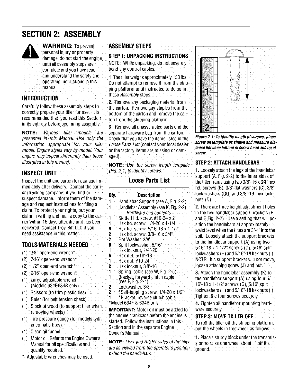
OperatingSymbols
w_s _bo_ (shownr_re,_ _crd_)
maybeusedonthellera_lmgine.
NOTEYour_mayr_thavealiof_s_.
FAST SLOW
STOP TILLERDIRECTION LEVERDIRECTION
• READTHEOWNER'SMANUAL.
• KNOWLOCATIONSAND FUNCTIONSOFALLCONTROLS.
• KEEPALLSAFETYDEVICESANDSHIELDSIN PLACEAND WORKING.
• NEVERALLOWCHILDRENORUNINSTRUCTEDADULTSTOOPERATETILLER.
• SHUTOFFENGINEANDDISCONNECTSPARKPLUGWIREBEFOREMANUALLYUN"
CLOGGINGTINESORMAKINGREPAIRS.
• KEEPBYSTANDERSAWAYFROMMACHINE.
• KEEPAWAYFROMROTATINGPARTS.
• USEEXTREMECAUTIONWHEN REVERSINGOR PULLINGTHEMACHINETOWARDS
YOU.
I-'-I Itl R
CHOKE CHOKE REVERSE
ON OFF ROTATINGTINES
<--o-->
TO AVOID SERIOUS INJURY:
BAIL BAIL
ENGAGED DISENGAGED
SECTION2: ASSEMBLY
WARNING: To prevent
personalinjury or property
damage,do notstart the engine
until all assemblysteps are
completeandyou have read
and understandthe safetyand
operatinginstructions in this
manual.
INTRODUCTION
Carefullyfollow these assemblysteps to
correctly prepareyour tiller for use. It is
recommendedthat you readthis Section
in itsentirety before beginning assembly.
NOTE: Various tiller models are
presented in this Manual Use only the Checkthat you havethe items listedin the
information appropriate for your tiller LooseParts List (contactyour localdealer
model Engine styles varyby model Your or the factory itemsare missing or dam-
engine may appear differently than those aged).
illustratedin thismanual.
INSPECTUNIT
Inspectthe unitand carton for damageLm-
mediatelyafter delivery. Contactthe cam-
er (trucking company) if you find or
suspectdamage. Inform them of the dam-
ageand request instructions for filing a 1
claim. Toprotect your rights, put your
claim inwriting andma_la copyto the car- 1
rier within 15 days after the unit has been 1
delive'ed. Contact Troy-Bilt LLCil you 6
needassistancein this matter. 2
TOOLSMATERIALSNEEDED
Ill 3,8" open-endwrench* 6 Hex nut. 5/16"-18 Iockwashers(.H)and5/16"-18 hexnuts (I).
(.2) 7/16' open-end wrench" 1 Hexnut #10-24 NOTE: If a support bracketwill not move
12_ 1/2" open-endwrench* 2 HexIocknut.3,8"-16 loosenattaching screw (J) and nut.
(2) 946"open-end wrench* 1 Spring, cable(see W, Fig.2-5_ 3. Attach the handlebarassembly (.K_to
(1) Largead Jstablewrench (.seeP, Fig.2-4_ 16"-18x 1-1/2" screws (.G_,5/16" split
_Models634F/634Bonly} 2 Lockwasher 3/8
(.1J Scissors to trim plasticties/
(1) Ruler (for belttension check_
111 Blockof wood (to support tiller when
remowng wheels)
111 Tire pressure gauge(for modelswith
pneumatictires_
Ill Cleanoil funnel
111 Motoroil Refertothe Engine0wner's
Manualfor oilspecificationsand
quantityrequired.
* Adjustablewrenches mayDeused,
ASSEMBLYSTEPS
STEP 1: UNPACKING INSTRUCTIONS
NOTE:While unpacking, do not severely
bendany control cables.
1.Thetiller weighsapproximately133 lbs.
Donot attempt to remove it from the ship-
ping platform until instructed to do so m
these Assembly steps.
2. Removeanypackagingmaterialfrom
the carton. Removeany staplesfrom the
bottom ofthe carton and removethe car-
ton from the shipping platform.
3. Removeall unassembledpartsand the
separatehardwarebagfrom the carton.
NOTE: Use the screw length template
(Fig.2-1) toidentify screws
LoosePartsList
Qty. Description
1
HandlebarSupport (seeA, Fig. 2-2_
HandlebarAssembly(seeK,Fig.2-2)
Hardwarebag contents:
Slotted hd. screw #10-24 x 2'
Hex hd. screw 1/4-20 x 1-1 '4
Hex hd. screw 5/16-18 x 1-1 2"
Hex hd. screw. 3/8-16 x 3/4
2
FlatWasher.3/8
6 Split Iockwashe_5/16"
1 HexIocknut. 1/4"-20 5Pi6"-18x 1-1/2" screws (G).5/16" split
1 Bracket.forward clutchcable the handlebarsupport (A) usingfour 5.
2
*Self-tappingscrew.1/4-20 x 1/2" IockwashersIHI and5/16"-18 hexnuts (I).
1 *Bracket reverseclutch cable
*Model 634F& 634B only
IMPORTANT:Motor oil must beaddedto
the enginecrankcase beforetheengine is
started. Followthe instructions inthis
Sectionand in the separateEngine
Owner'sManual.
NOTE: LEFTandRIGHTsidesofthetiller sion to raise one wheelabout l" off the
are as viewedfrom the operator's position ground.
behind the handlebars.
Figure2-1: Toidentifylengthofscrews,place
screwontemplateasshownandmeasuredis-
tancebetweenbottomofscrewheadandtipof
scrBw,
STEP 2: ATTACH HANDLEBAR
1. Looselyattach the legsof the handlebar
support (A, Fig.2-2) to the innersides of
thetiller frame usingtwo 3/8"-16x 3/4"hex
hd. screws (B), 3/8"flat washers(C), 3/8"
lock washers (GG_,and 3/8"-16 hexlock-
nuts (D_,
2. Therearethree height adjustment holes
in the two handlebarsupport brackets (.E
and E Fig. 2-2). Usea setting that will po-
sition the handlebarsat approximately
waist levelwhenthetines are3"-4"intothe
so_l. Looselyattachthe support brackets
to the handlebarsupport (.A_using two
Tightenthe four screwssecurely
4. Tighten all handlebarmounting hard-
waresecurely.
STEP3: MOVE TILLER OFF
Toroll thetiller off the shipping platform.
put the wheels in freewhee asfollows:
1. Placeasturdy block underthe transmis-
m
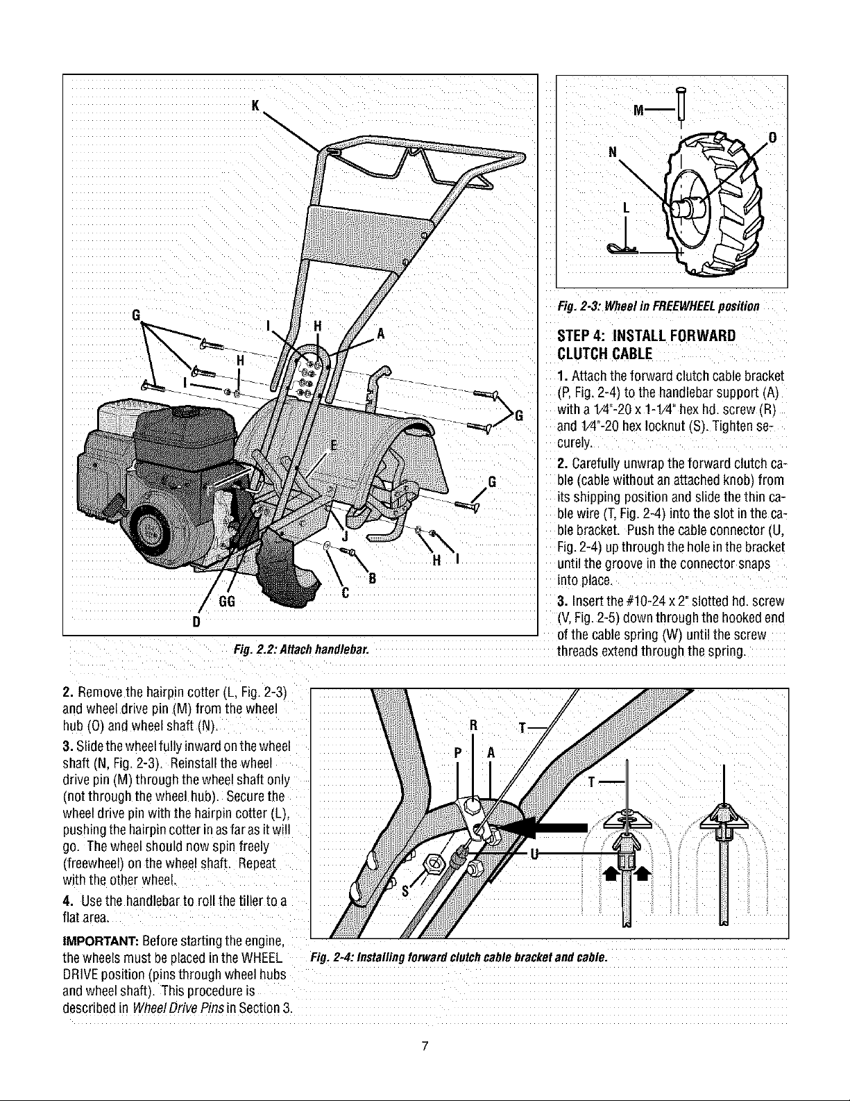
Fig.2,2:AHachhandlebar, threads extendthrough the spring.
2. Removethe hairpin cotter (L, Fig.2-3)
and wheel drive pin (M) from the wheel
hub (0) and wheel shaft (N).
3. Slidethe wheelfully inwardonthewheel
shaft (N, Fig.2-3). Reinstallthe wheel
drive pin (M) through the wheelshaft only
(not through the wheel hub). Securethe
wheeldrive pin with the hairpin cotter (L),
pushingthe hairpincotter inasfar asit will
go. Thewheel should now spin freely
(freewheel) on the wheel shaft. Repeat
with the other wheel.
4. Usethe handlebarto roll the tiller to a
flat area.
Fig. 2-3: Wheelin FREEWHEELposition
STEP4: INSTALL FORWARD
CLUTCH CABLE
1. Attach the forward clutch cablebracket
(P,Fig.2-4) to the handlebarsupport AI
with a1/4"-20x 1-1/42hexhd. screw (R)
and V4"-20 hexIocknut (S). Tightense-
curely.
2. Carefullyunwrapthe forward clutch ca-
ble (cable without anattachedknob, from
its shipping position and slidethe thin ca-
ble wire (T.Fig.2-4 intothe slot in the ca-
ble bracket. Pushthe cable connector (U.
Fig.2-4) upthrough the holein the bracket
until the groove inthe connector snaps
into place.
3. Insertthe #10-24 x 2"slotted hd.screw
(V,Fig.2-5) downthrough the hookedend
of the cable spring (W) until the screw
IMPORTANT:Beforestarting theengine,
thewheels must beplacedin the WHEEL Fig.2=4:Installingforwardclutchcablebracketandcable.
DRIVEposition (pins through wheelhubs
andwheelshaft). This procedureis
described in WheelDrivePinsin Section3.
4. Threadthe #10-24 hexnut (Z,Fig. 2-5)
halfwayonto the screw (V).
5. Threadthe screw IV_into thecable ad-
juster (X).
6. Hookthe cable spring (W,Fig.2-6) into
theV-shaoedbend in the ForwardClutch
Bail _Y).
7. Checkfor correcttension ontheforward
drive belt by taking two measurementsof
thecablespnng, asfollows:
a. With the ForwardClutch Bail(Y,Fig.2-
6/in an open(released)position, measure
thelength ofthecablespring (W from the
outermost coil to the outermost coil.
n. Squeezethe ForwardClutchBailagainst
the handlebar(see Fig. 2-7_and re-mea-
surethe spring length, Thebelt tensionis
correct if this second measurementis be-
Fig.2-7: Tocheckforwardbelttension,taketwomeasurementsofthelengthofthecoilsinthe
spring-- firstwiththebailopen,thenwiththebailheldagainstthehandlebar.
tween 1/16"to 3/16"longer than thefirst
measurement. If so. turn the hexnut (Z.
Fig.2-7) tightly against the cableadjuster
(X_while preventingthe cableadjuster
from turnmg.
c. Ifthe spring length is incorrect, you
mustadjust the cabletension asdescribed
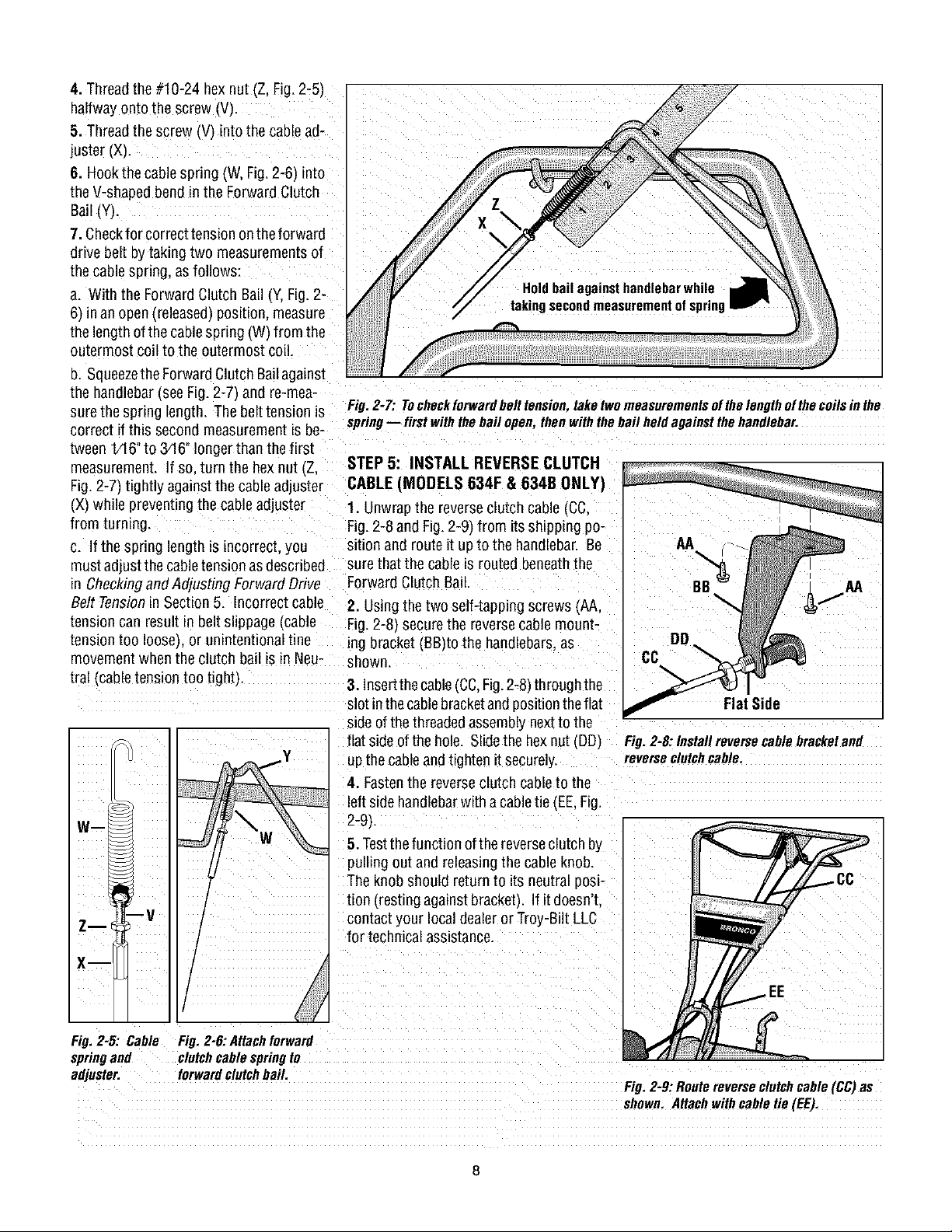
STEP 5: INSTALL REVERSECLUTCH
CABLE (MODELS 634F & 634B ONLY)
1. Unwrapthe reverseclutch cable(CC.
Fig.2-8 and Fig.2-9_from itsshipping po-
sition and route it upto the handlebar. Be
surethat the cableis routed beneaththe
in Checkingand Adjustin_ ForwardDrive Forward Clutch Bail.
Belt Tensionin Section 5. Incorrectcable
tension can result in belt slippage Icable
tension too IooseLor unintentional tine
movement when the clutch bail is in Neu-
tral Icable tension too tight}
2. Usingthe two self-tapping screws (AA,
Fig.2-8) securethe reversecable mount-
ing bracket(BB)to the handlebars,as
show_
3. Insertthe cable(CC,Fig.2-8) through the
slot inthecablebracketandpositiontheflat
sideofthe threadedassemblynextto the
flat sideof the hole. Slidethe hex nut (DD/
up the cable andtighten it securely
4. Fastenthe reverseclutch cable to the
left side handlebarwith a cabletie (EE,Fig.
Wm
2-9L
5. Testthefunction ofthe reverseclutch by
pulling out and releasing the cableknob.
Theknob should return to its neutral posi-
tion (resting against bracketL Ifit doesn't.
Zm
contact your localdealer or Troy-Bilt LLC
for technical assistance.
X--
CC
Flat Side
Fig. 2-8: Install reverse cable bracketand
reverseclutch cable,
Fig, 2-5: Cable
springand
adjuster.
Fig. 2-6: Attachforward
clutch cable spring to
forwardclutchbail.
Fig.2-9:Routereverseclutchcable(CC)as
shown.Attachwithcabletie(EL:).
31bY I_: L;I'IEL;KLEVEL UI-
Thetransmission wasfilled with gearoil at
thefactory.However,youshouldcheckthe
gearoil levelatthis timeto makecertain it
is correct.
IMPORTANT:Donot operatethe tiller if the
gearoil levelis low. Doingso will result in
severedamageto thetransmission com-
ponents.
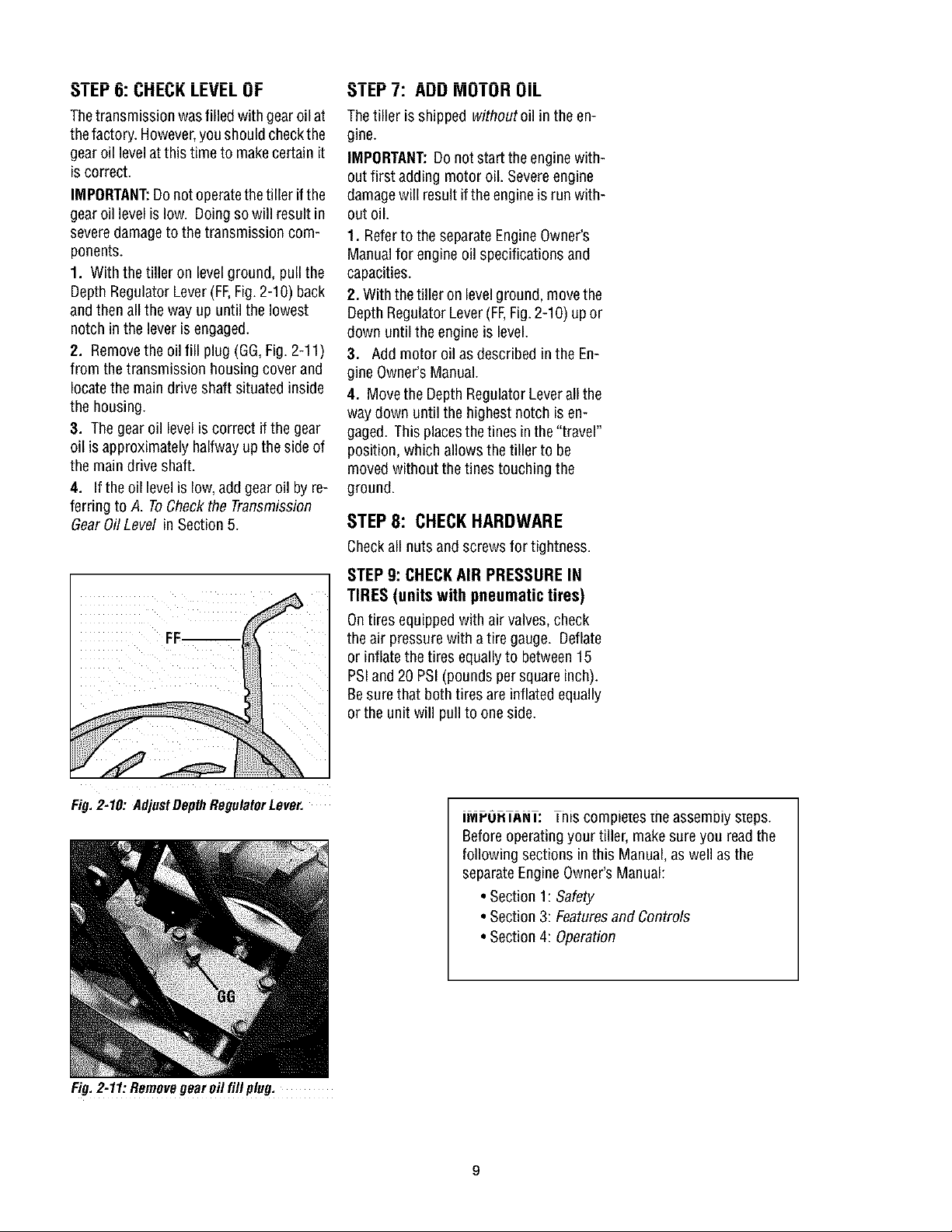
1. With the tiller on levelground, pull the
Depth RegulatorLever(FF,Fig.2-10) back
andthen all the way up until the lowest
notch inthe lever isengaged.
2. Removethe oil fill plug (GG,Fig.2-11)
from the transmission housingcover and
locatethe main drive shaft situated inside
the housing.
3. Thegear oil level is correct ifthe gear
oil isapproximately halfwayup theside of
the maindrive shaft.
4. If the oil levelis low,add gear oil byre-
ferring to A. ToCheckthe Transmission
GearOil Level inSection 5.
_IbY I: AUU MUIUH UIL
Thetiller isshipped withoutoil in theen-
gine.
IMPORTANT:Do not start theengine with-
outfirst adding motor oil. Severeengine
damagewill resultifthe engineis run with-
out oil.
1. Referto the separateEngineOwner's
Manualfor engine oil specifications and
capacities.
2. With thetiller on levelground, movethe
Depth RegulatorLever(FF,Fig.2-10) upor
down until the engineis level.
3. Add motor oil asdescribed in the En-
gine Owner'sManual.
4. Movethe DepthRegulatorLeverall the
way down until the highest notch is en-
gaged. This placesthetines in the "travel"
position, which allows the tiller to be
moved without thetines touching the
ground.
STEP8: CHECKHARDWARE
Checkall nuts and screws for tightness.
STEP 9: CHECKAIR PRESSURE IN
TIRES (units with pneumatic tires)
Ontires equipped with air valves, check
theair pressurewith atire gauge. Deflate
or inflatethe tires equallyto between15
PSIand20 PSI(pounds per squareinch).
Besure that both tires are inflated equally
orthe unit will pullto one side.
Fig. 2-10: AdjustDepth RegulatorLever.
Fig.2-11:Removegearoil fill plug,
IMrU. lANl: his compie[esme assemoiy steps.
Beforeoperatingyour tiller, makesure you readthe
following sections in this Manual,as well as the
separateEngineOwner'sManual:
• Section1: Safety
• Section3: Featuresand Controls
• Section4: Operation
SECTION3: FEATURESANDCONTROLS
WARNING: Before
operatingyour machine,
carefully readand understand
all safety, controls and
operatinginstructions in this
Manual,the separateEngine
Owner's Manual,and on the
decalson the machine.
Failureto follow these
instructions canresult in
serious personal injury.
INTRODUCTION
This Section describesthe location and
function of the controls onyour tiller. Re-
ferto thefollowing Section,Operationfor
detailedoperating instructions.
Practiceusing these controls, with the en-
gine shut off, until you understandthe op-
eration ofthe controls andfeelconfident
with eachof them.
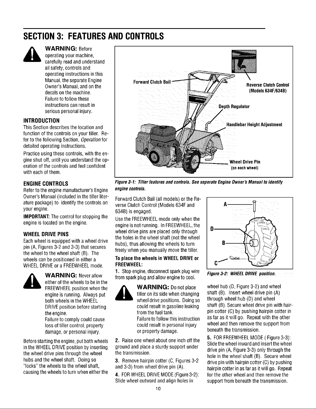
Forward
Reverse ClutchControl
(Models634F/634B)
DepthRegulator
Handlebar HeightAdjustment
Wheel Drive Pin
(oneachwheel)
ENGINE CONTROLS
Referto the engine manufacturer's Engine
Owner'sManual (included inthe tiller liter-
ature package)to identify the controls on
your engine.
IMPORTANT:Thecontrol for stopping the
engine is locatedon the engine.
WHEEL DRIVE PINS
Eachwheel is equippedwith awheeldrive
pin (A, Figures3-2 and 3-3) that secures
thewheelto the wheel shaft (B). The
wheelscan be positioned ineither a
WHEELDRIVEora FREEWHEELmode.
WARNING: Neverallow
eitherof thewheelsto bein the
FREEWHEELposition whenthe
engineis running. Alwaysput
both wheelsin theWHEEL
DRIVEposition beforestarting
theengine.
Failureto comply could cause
loss of tiller control, property
damage,or personalinjury.
Beforestarting theengine,put both wheels
in the WHEELDRIVEposition byinserting
thewheel drive pins through the wheel
hubsand the wheel shaft. Doingso
"locks" the wheels to the wheel shaft,
causingthe wheelsto turn wheneitherthe
Figure3-1: Tillerfeaturesandcontrols.SeeseperateEngineOwner'sManualtoidentify
enginecontrols.
Forward Clutch Bail (all models) or the Re-
verseClutch Control (Models 634Fand
634B) is engaged.
Usethe FREEWHEELmode only whenthe
engineis not running. In FREEWHEEL,the
wheeldrive pins are placed only through
theholes in thewheelshaft (not the wheel
hubs), thus allowing the wheelsto turn
freely whenyou manuallymovethe tiller.
Toplacethe wheels in WHEELDRIVEot
FREEWHEEL:
1. Stopengine,disconnectsparkplugwire
from sparkplug andallowengineto cool.
WARNING: Donot place
tiller on its side when changing
wheeldrive positions. Doing so
could result in gasoline leaking
from thefuel tank.
Failureto follow this instruction
could result in personal injury
or propertydamage.
2. Raiseonewheelabout one inch off the
ground and placea sturdy support under
thetransmission.
3. Removehairpin cotter (C, Figures3-2
and 3-3) from wheel drive pin (A).
4. FORWHEELDRIVEMODE(Figure3-2):
Slide wheel outward and align holes in
10
Figure3-2: WHEELDRIVE position.
wheelhub (D,Figure3-2) and wheel
shaft (B). Insert wheeldrive pin (A)
through wheel hub (D)and wheel
shaft (B). Securewheeldrive pinwith hair-
pin cotter (C) by pushing hairpincotter in
asfar as it will go. Repeatwith the other
wheeland then removethesupport from
beneaththe transmission.
5. FORFREEWHEELMODE( Figure3-3):
Slidethe wheelinwardand insertthewheel
drive pin (A, Figure3-3) onlythrough the
hole in the wheel shaft (B). Secure wheel
drive pinwith hairpincotter (C)by pushing
hairpin cotter inasfaras it will go. Repeat
for the other wheeland then removethe
support from beneaththe transmission.
 Loading...