

Troybilt 21A-634A766 Owner’s Manual
®
O m m 'W//////aI&_AIIIIIIIIIIIIIF
Operator's Manual
/ m mllllllllllllllllml m
Rear-tine Tiller Models
630C--Tuffy
634AmSuper BroncoTM
Mode1634A Shown
IMPORTANT: Read safety rules and instructions carefully before operating equipment.
Warning: This unit is equipped with an internal combustion engine and should not be used on or near any unimproved forest-covered, brush-
covered or grass-covered land unless the engine's exhaust system is equipped with a spark attester meeting applicable local or state laws (if
any). If a spark arrester is used, it should be maintained in effective working order by the operator. In the State of California the above is required
by law (Section 4442 of the California Public Resources Code). Other states may have similar laws. Federal laws apply on federal lands. A spark
arrester for the muffler is available through your nearest engine authorized service dealer or contact the service department, P.O. Box 361131
Cleveland, Ohio 44136-0019.
Troy-Bilt LLC,P.O.BOX361131CLEVELAND,OHIO44136-0019
PRINTEDINU.S.A. FORMNO. 770-10594E
9/9/04
TABLEOFCONTENTS
Content Page Content Page
Customer Support 2 Maintenance 17
Safety 3 Off-season Storage 21
Assembly 6 Troubleshooting 22
Features and Controls 10 Parts List 23
Operation 12 Warranty Back Cover
FINDINGMODELNUMBER
This Operator's Manual is an important part of your new lawn tractor. It will help you assemble, prepare and maintain the
unit for best performance. Please read and understand what it says.
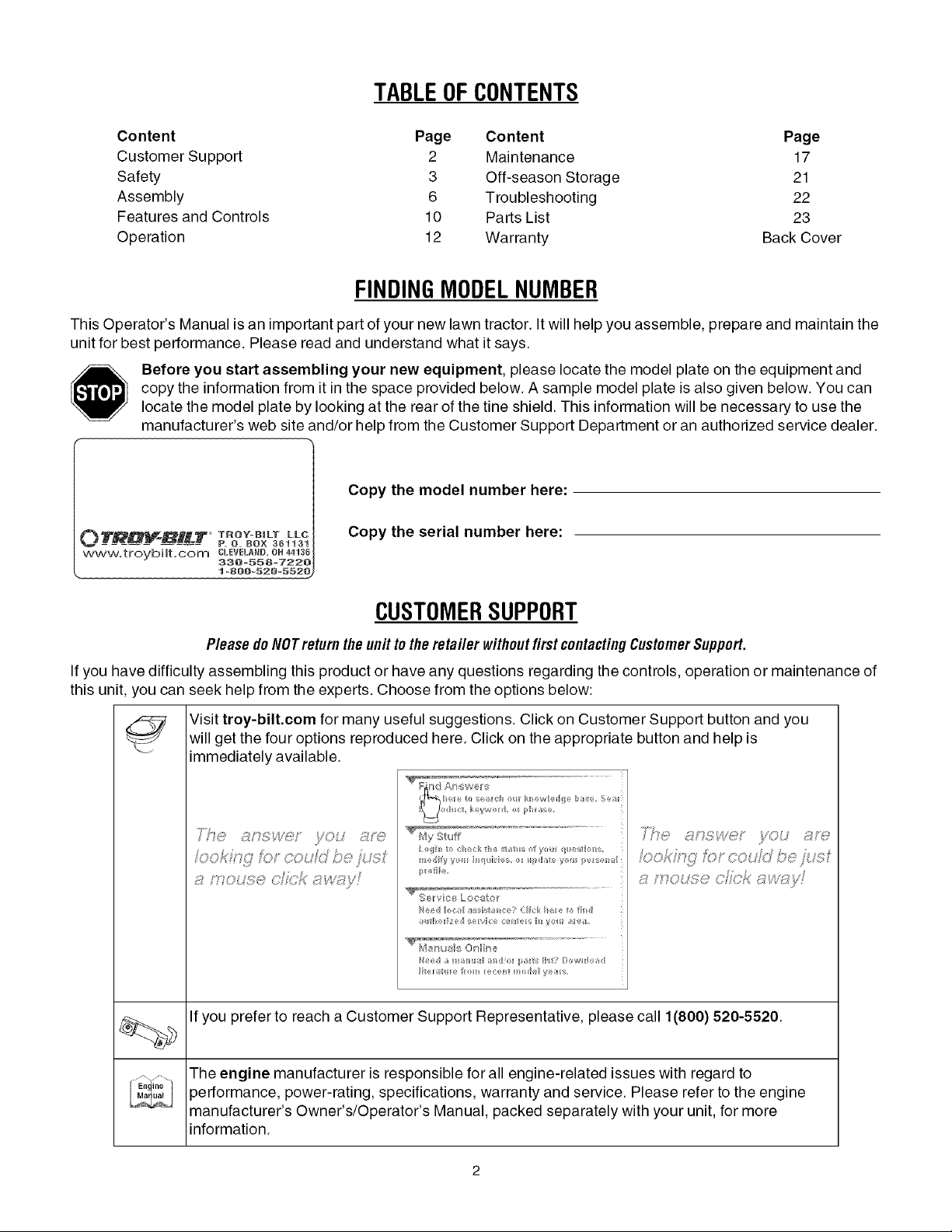
Before you start assembling your new equipment, please locate the model plate on the equipment and
copy the information from it in the space provided below. A sample model plate is also given below. You can
locate the model plate by looking at the rear of the tine shield. This information will be necessary to use the
manufacturer's web site and/or help from the Customer Support Department or an authorized service dealer.
Copy the model number here:
OTRDV-BILT T,OV-BmLTLLC
www.troybilt.com CLEVELAND,OH44136
,. 1-800-520-552_
P. O. BOX 361131
330-558-7220
Copy the serial number here:
CUSTOMERSUPPORT
PleasedoNOTreh/m thel/nit totheretailer withoutfirstcontactingCustomerSupport.
If you have difficulty assembling this product or have any questions regarding the controls, operation or maintenance of
this unit, you can seek help from the experts. Choose from the options below:
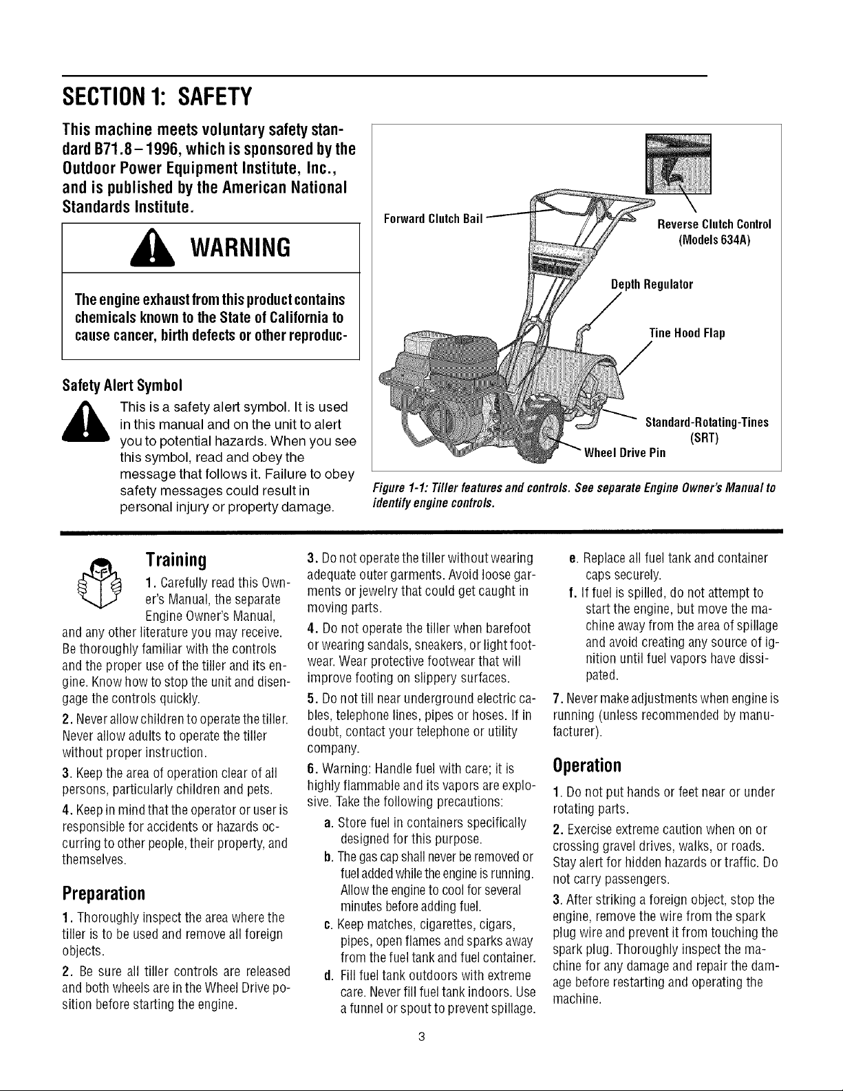
Visit troy-bilt.com for many useful suggestions. Click on Customer Support button and you
will get the four options reproduced here. Click on the appropriate button and help is
immediately available.
_ 7>,,,,
/;/ ,> ;'V }/ )
..... f ; @; t ;D
j;_ ?" #'s " 4t, ' F_ i/!s ,
* ;,, #FOX }_ j,"
,,, >,, rL;," ¢j ,_ <# ft, *x J ,7;; _
'_,-., _tf';_'ivc ,l
,v yO, ,_;7f'_;:'
If you prefer to reach a Customer Support Representative, please call 1(800) 520-5520.
The engine manufacturer is responsible for all engine-related issues with regard to
performance, power-rating, specifications, warranty and service. Please refer to the engine
manufacturer's Owner's/Operator's Manual, packed separately with your unit, for more
information.
SECTION1: SAFETY
This machine meets voluntary safety stan-
dard B71.8-1996, which is sponsoredbythe
Outdoor Power Equipment Institute, Inc.,
and is published by the American National
Standards Institute.
WARNING
The engine exhaustfromthisproductcontains
chemicals known to the State of California to
cause cancer, birth defects or other reproduc-
SafetyAlertSymbol
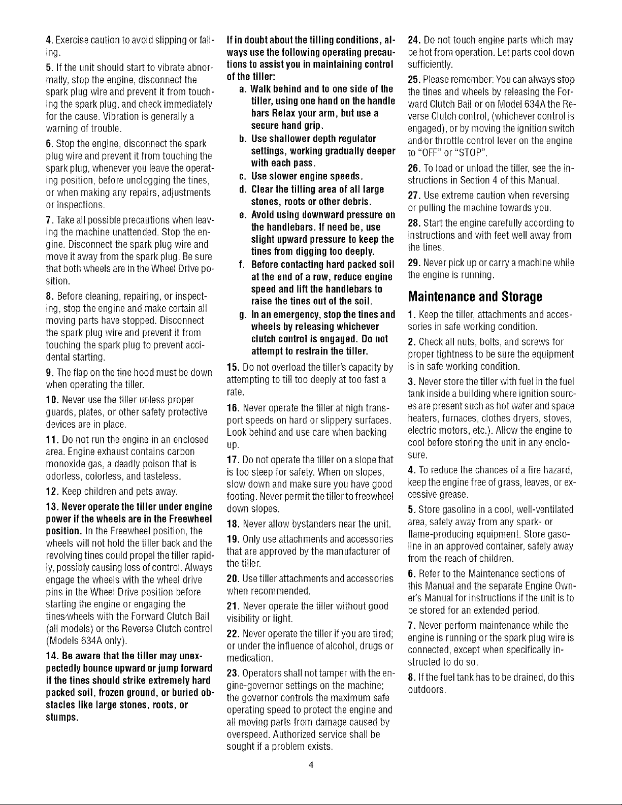
ForwardClutchBail
ReverseClutchControl
(Models634A)
DepthRegulator
TineHoodFlap
,_ This is a safety alert symbol. It is used
and anyother literature you may receive.
Bethoroughly familiar with the controls
andthe proper useof the tiller and its en-
gine. Knowhowto stopthe unit and disen-
gagethe controls quickly.
2. Neverallow childrento operatethe tiller.
Neverallow adults to operatethe tiller
without proper instruction.
3. Keepthe areaof operationclear of all
persons, particularly children and pets.
4. Keepin mindthattheoperatoror useris
responsible for accidents or hazardsoc-
curring to otherpeople,their property,and
themselves.
in this manual and on the unit to alert
you to potential hazards. When you see
this symbol, read and obey the
message that follows it. Failure to obey
safety messages could result in
personal injury or property damage.
3. Donot operatethetiller without wearing
1. Carefully readthis Own-
Training
er's Manual,the separate
Engine Owner'sManual,
adequateouter garments.Avoid loosegar-
ments or jewelry that could get caught in
moving parts.
4. Do not operatethe tiller when barefoot
or wearingsandals, sneakers,or light foot-
wear.Wear protective footwear that will
improve footing on slippery surfaces.
5. Do nottill nearundergroundelectric ca-
bles,telephone lines, pipes or hoses.If in
doubt, contact your telephoneor utility
company.
6. Warning: Handlefuel with care; it is
highly flammableandits vapors areexplo-
sive.Takethe following precautions:
a. Storefuel in containers specifically
b. Thegascapshall neverberemovedor
Preparation
1. Thoroughly inspect the areawherethe
tiller is to be usedand removeallforeign
objects.
2. Be sure all tiller controls are released
and bothwheels arein theWheelDrive po-
sition beforestarting the engine.
c. Keepmatches,cigarettes, cigars,
d. Fillfuel tank outdoors with extreme
Standard-Rotating-Tines
(SRT)
DrivePin
Figure 1-1: Tiller featuresand contre/s. SeeseparateEngine Owner'sManua/ to
identifyenginecontre/s.
e. Replaceall fueltank and container
caps securely.
f. If fuel isspilled, do not attempt to
start the engine,but move the ma-
chineawayfrom the areaof spillage
and avoidcreating any source of ig-
nition until fuel vapors havedissi-
pated.
7. Nevermakeadjustments whenengineis
running (unless recommendedby manu-
facturer).
Operation
1. Do not put hands or feet nearor under
rotating parts.
designedfor this purpose.
fueladdedwhiletheengineis running.
Allowthe engineto coolforseveral
minutesbeforeaddingfuel.
pipes, openflamesandsparks away
from thefueltank andfuelcontainer.
care.Neverfill fuel tank indoors. Use
a funnelor spout to preventspillage.
2. Exerciseextremecautionwhen on or
crossing gravel drives,walks, or roads.
Stayalert for hiddenhazardsor traffic. Do
not carry passengers.
3. After striking a foreign object, stop the
engine,removethe wire from the spark
plug wire and prevent it from touching the
spark plug. Thoroughly inspectthe ma-
chine for any damageand repairthe dam-
agebefore restarting and operatingthe
machine.
4.Exercisecautiontoavoidslippingorfall-
ing.
5.Iftheunitshouldstarttovibrateabnor-
mally,stoptheengine,disconnectthe
sparkplugwireandpreventitfromtouch-
ingthesparkplug,andcheckimmediately
forthecause.Vibrationisgenerallya
warningoftrouble.
6. Stopthe engine, disconnectthe spark
plug wire and prevent it from touching the
spark plug,wheneveryou leavethe operat-
ing position, before unclogging thetines,
or whenmakingany repairs, adjustments
or inspections.
7. Takeall possible precautionswhen leav-
ing the machine unattended.Stopthe en-
gine. Disconnectthespark plug wire and
move it awayfrom thespark plug. Besure
that both wheelsarein the WheelDrive po-
sition.
8. Before cleaning,repairing,or inspect-
ing, stop the engine and make certain all
moving parts havestopped. Disconnect
the spark plug wire and prevent it from
touching thespark plug to preventacci-
dentalstarting.
9. Theflapon thefine hood must bedown
when operatingthetiller.
10. Neverusethetiller unless proper
guards, plates,or other safety protective
devicesare in place.
11. Do not run the engine in an enclosed
area.Engineexhaust containscarbon
monoxide gas,adeadlypoison that is
odorless, colorless, and tasteless.
12. Keepchildren and pets away.
13. Never operate the tiller underengine
powerif thewheels areinthe Freewheel
position.In the Freewheelposition, the
wheelswill not hold the tiller back andthe
revolvingtines could propel thetiller rapid-
ly,possibly causingloss of control. Always
engagethe wheels with the wheel drive
pins in theWheel Drive position before
starting the engineorengagingthe
tines4Nheelswith the Forward Clutch Bail
(all models) or the ReverseClutchcontrol
(Models 634A only).
14. Be awarethat the tiller may unex-
pectedlybounceupwardorjumpforward
if the tinesshouldstrike extremelyhard
packedsoil, frozen ground,or buriedob-
stacleslike large stones,roots,or
stumps.
If indoubtaboutthetilling conditions, al-
ways usethe following operating precau-
tionsto assistyouin maintainingcontrol
of the tiller:
a. Walk behindandto one side of the
tiller, usingone handonthehandle
barsRelax yourarm, but use a
securehandgrip.
b. Useshallowerdepthregulator
settings,working graduallydeeper
with eachpass.
¢. Useslowerenginespeeds.
d. Clearthetilling area of all large
stones,rootsor other debris.
e. Avoidusingdownwardpressureon
thehandlebars. If needbe, use
slight upwardpressuretokeep the
tinesfrom diggingtoodeeply.
f. Beforecontacting hardpackedsoil
at the endof a row, reduceengine
speedand lift thehandlebarsto
raise thetines out of the soil.
g. In anemergency,stopthetinesand
wheels byreleasingwhichever
clutch controlis engaged.Do not
attemptto restrainthetiller.
15. Do not overloadthe tiller's capacityby
attempting to till too deeply at too fast a
rate.
16. Neveroperatethetiller at high trans-
port speeds on hard or slippery surfaces.
Look behind and usecare when backing
up.
17. Donot operatethetiller on aslopethat
is too steepfor safety.When onslopes,
slow down and makesure you havegood
footing. Neverpermit thetillerto freewheel
down slopes.
18. Neverallowbystandersnearthe unit.
19. Onlyuseattachmentsand accessories
that are approved bythe manufacturerof
the tiller.
20. Usetiller attachmentsand accessories
when recommended.
21. Neveroperatethetiller without good
visibility or light.
22. Neveroperatethe tiller ifyou aretired;
or underthe influence ofalcohol, drugs or
medication.
23. Operatorsshall nottamper with theen-
gine-governor settings onthe machine;
the governor controls the maximum safe
operatingspeed to protect the engine and
all moving parts from damagecaused by
overspeed.Authorized serviceshall be
sought if a problem exists.
24. Do nottouch engine parts which may
behot from operation.Let partscool down
sufficiently.
25. Pleaseremember:Youcan alwaysstop
thetines andwheelsby releasingthe For-
ward ClutchBailoron Model634Athe Re-
verseClutchcontrol, (whichevercontrol is
engaged),or bymovingthe ignition switch
and/orthrottle control lever on the engine
to "OFF" or"STOP".
26. To loador unloadthe tiller, seethe in-
structions in Section4 of this Manual.
27. Useextremecaution when reversing
or pulling the machinetowards you.
28. Starttheenginecarefully accordingto
instructions and with feet well away from
thetines.
29. Neverpick up or carry a machinewhile
the engineis running.
MaintenanceandStorage
1. Keepthe tiller, attachmentsand acces-
sories in safeworking condition.
2. Checkall nuts, bolts, and screws for
proper tightnessto besurethe equipment
is in safeworking condition.
3. Neverstore thetiller with fuel in thefuel
tank insidea building whereignition sourc-
esare presentsuchas hot waterandspace
heaters,furnaces, clothes dryers, stoves,
electric motors, etc.). Allow the engineto
cool beforestoring the unit in anyenclo-
sure.
4. To reducethe chancesof a fire hazard,
keepthe enginefreeof grass, leaves,or ex-
cessivegrease.
5. Store gasolinein acool, well-ventilated
area,safely awayfrom any spark- or
flame-producing equipment. Store gaso-
line in anapprovedcontainer,safelyaway
from the reachof children.
6. Refertothe Maintenancesectionsof
this Manualandthe separateEngineOwn-
er'sManualfor instructions ifthe unitis to
bestored for an extendedperiod.
7. Neverperform maintenancewhilethe
engineis running orthe spark plug wire is
connected,exceptwhen specifically in-
structed to do so.
8. Ifthefueltank hasto be drained,dothis
outdoors.
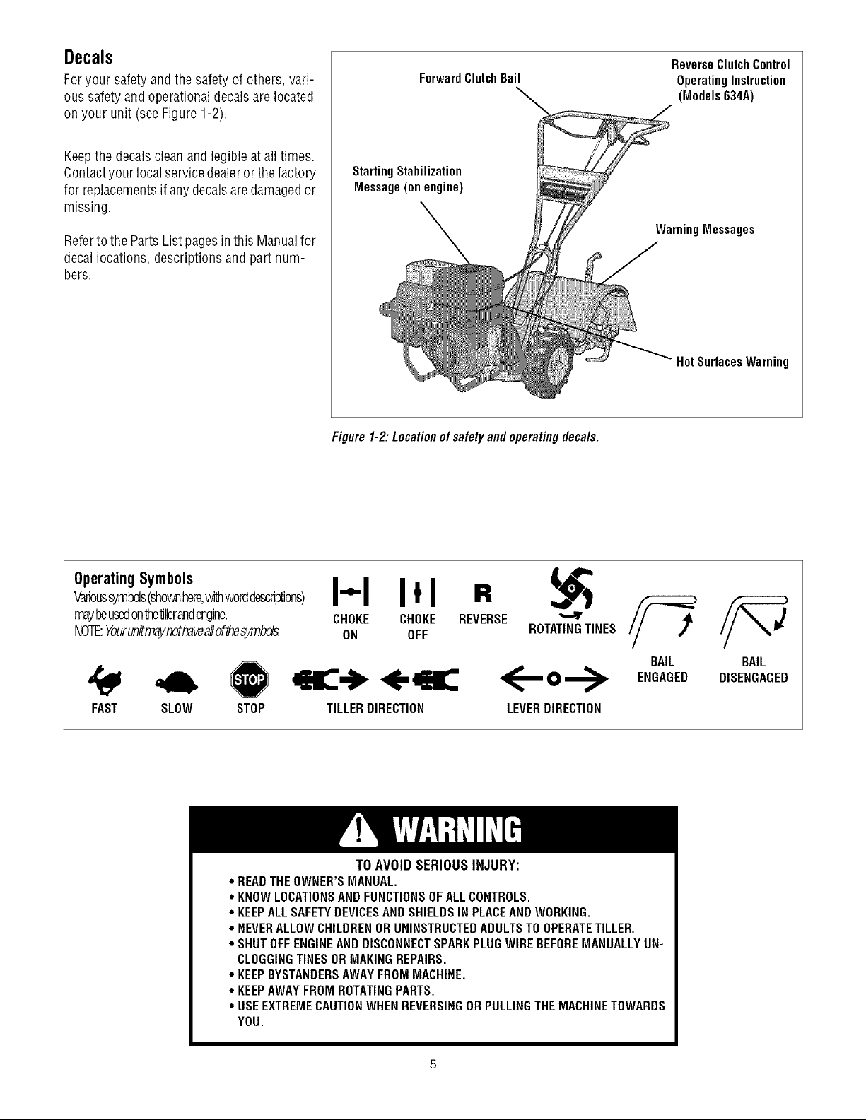
Decals
Foryour safety and the safety of others, vari-
ous safety and operationaldecalsarelocated
on your unit (seeFigure 1-2).
Keepthe decalsclean and legibleatall times.
Contactyour localservicedealeror thefactory
for replacementsif anydecalsaredamagedor
missing.
Referto the PartsListpagesin this Manualfor
decallocations, descriptionsandpart num-
bers.
ForwardClutchBail
StartingStabilization
Message(on engine)
Figure 1-2: Locationofsafety and operatingdeca/s.
ReverseClutch Control
OperatingInstruction
(Models 634A)
WarningMessages
HotSurfacesWarning
OperatingSymbols
Varioussymbols(shownhere,withworddescriptions)
mayheusedonte'dllerandengine.
NOTE:Yourunitmaynothaveallof_esymbds.
FAST SLOW STOP
* READTHEOWNER'SMANUAL.
* KNOWLOCATIONSAND FUNCTIONSOFALLCONTROLS.
* KEEPALLSAFETYDEVICESANDSHIELDSIN PLACEAND WORKING.
° NEVERALLOWCHILDRENORUNINSTRUCTEDADULTSTO OPERATETILLER.
° SHUTOFFENGINEANDDISCONNECTSPARKPLUGWIREBEFOREMANUALLYUN-
CLOGGINGTINESORMAKINGREPAIRS.
° KEEPBYSTANDERSAWAYFROMMACHINE.
° KEEPAWAYFROM ROTATINGPARTS.
° USEEXTREMECAUTIONWHENREVERSINGOR PULLINGTHEMACHINETOWARDS
YOU.
I"1 I*1 R
CHOKE CHOKE REVERSE
ON OFF ROTATINGTINES
TILLERDIRECTION LEVERDIRECTION
TO AVOID SERIOUS INJURY:
BAIL
ENGAGED
BAIL
DISENGAGED
SECTION2: ASSEMBLY
WARNING: Toprevent
personalinjury or property
damage,do notstart the engine
until all assemblysteps are
completeandyou haveread
and understandthesafety and
operatinginstructions in this
manual.
INTRODUCTION
Carefullyfollow theseassemblysteps to
correctly prepareyour tiller for use. It is
recommendedthatyou readthis Sectionin
its entirety beforebeginning assembly.
NOTE: Various rifler models are
presented in this Manual. Use only the
information appropriate for your tiller
model. Engine styles vary by model, Your
engine may appear differently than those
illustrated in this manual
INSPECTUNIT
Inspect the unitandcarton for damageim-
mediatelyafter delivery.Contactthe carrier
(trucking company) if you find or suspect
damage. Inform them of the damageand
request instructions for filing a claim. To
protect your rights, put your claim in writ-
ing andmaila copyto the carrierwithin 15
days afterthe unit has beendelivered.
ContactTroy-Bilt LLCif you needassis-
tance in this matter.
TOOLS/ MATERIALSNEEDED
(2) 1/2" open-end wrench*
(2) 9/16" open-endwrench*
(1) 3/8" open-endwrench*
(1) Largeadjustable wrench
(Models 634F/634Aonly)
(1) Scissors (totrim plasticties)
(1) Ruler (for belttension check)
(1) Block of wood (to support tiller when
removing wheels)
(1) Tirepressuregauge (for models with
pneumatictires)
(1) Cleanoil funnel
(1) Motor oil. Refertothe EngineOwner's
Manualfor oil specificationsand
quantityrequired.
* Adjustable wrenchesmay be used.
ASSEMBLYSTEPS
STEP 1: UNPACKING INSTRUCTIONS
NOTE:While unpacking,do not severely
bend anycontrol cables.
1.The tiller weighs approximately 133 Ibs.
Do notattemptto remove it from the ship-
ping platform until instructed to do so in
these Assemblysteps.
2. Removeany packagingmaterial from
the carton. Removeany staplesfrom the
bottom of the carton and removethe car-
ton from the shipping platform.
3. Removeall unassembledpartsandthe
separatehardwarebagfrom the carton.
Checkthat you havethe items listed in the
LooseParts List (contactyour local dealer
or the factory items aremissing or dam-
aged).
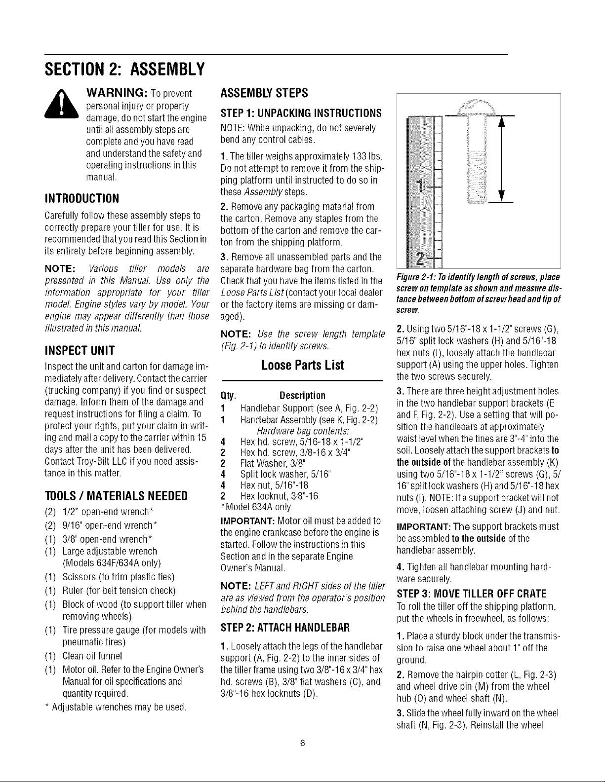
NOTE: Use the screw length template
(Fig,2-1) to identify screws,
LoosePartsList
Qty. Description
1 HandlebarSupport (seeA, Fig. 2-2)
1 HandlebarAssembly(seeK,Fig.2-2)
Hardwarebag contents:
4 Hexhd. screw,5/16-18 x 1-1/2"
2 Hexhd. screw,3/8-16 x 3/4"
2 FlatWasher,3/8"
4 Split lockwasher,5/16"
4 Hex nut, 5/16"-18
2 HexIocknut, 34}"-16
*Model 634A only
IMPORTANT:Motor oil must beaddedto
the enginecrankcasebefore theengine is
started. Followthe instructions inthis
Sectionand in the separateEngine
Owner's Manual.
NOTE: LEFTand RIGHTsidesof thetiller
are as viewedfrom the operator's position
behind thehandlebars.
STEP 2: ATTACHHANDLEBAR
1. Looselyattachthe legsof thehandlebar
support (A, Fig. 2-2) to the inner sides of
the tiller frameusingtwo 3/8"-16x3/4" hex
hd. screws (B), 3/8" flat washers(C), and
3/8"-16 hex Iocknuts (D).
_iiii
Figure2-1: Toidentifylengthofscrews,place
screwontemplateasshownandmeasuredis-
tancebetweenbottomofscrewheadandtipof
screw.
2. Usingtwo5/16"-18 x 1-1/2"screws(G),
5/16" split lock washers (H) and 5/16"-18
hexnuts (I), loosely attachthe handlebar
support (A) usingthe upperholes.Tighten
thetwo screws securely.
3. Therearethree height adjustmentholes
in the two handlebar support brackets (E
and F,Fig.2-2). Usea setting that will po-
sition the handlebarsat approximately
waist levelwhenthe tines are3"-4"intothe
soil. Looselyattachthe support bracketsto
theoutsideofthe handlebarassembly(K)
usingtwo 5/16"-18x 1-1/2" screws (G),5/
16"split lockwashers(H)and5/16"-18 hex
nuts (I). NOTE:Ifa support bracketwill not
move, loosenattaching screw (J) and nut.
IMPORTANT:The support bracketsmust
beassembledto theoutsideof the
handlebarassembly.
4. Tightenall handlebarmounting hard-
waresecurely.
STEP 3: MOVE TILLER OFF CRATE
Toroll the tiller off the shipping platform,
put the wheelsinfreewheel,asfollows:
1. Placeasturdy block underthetransmis-
sion to raiseonewheel about 1" off the
ground.
2, Removethe hairpin cotter (L, Fig.2-3)
and wheeldrive pin (M) from the wheel
hub (0) and wheelshaft (N).
3. Slidethe wheelfully inward onthewheel
shaft (N, Fig.2-3). Reinstallthe wheel
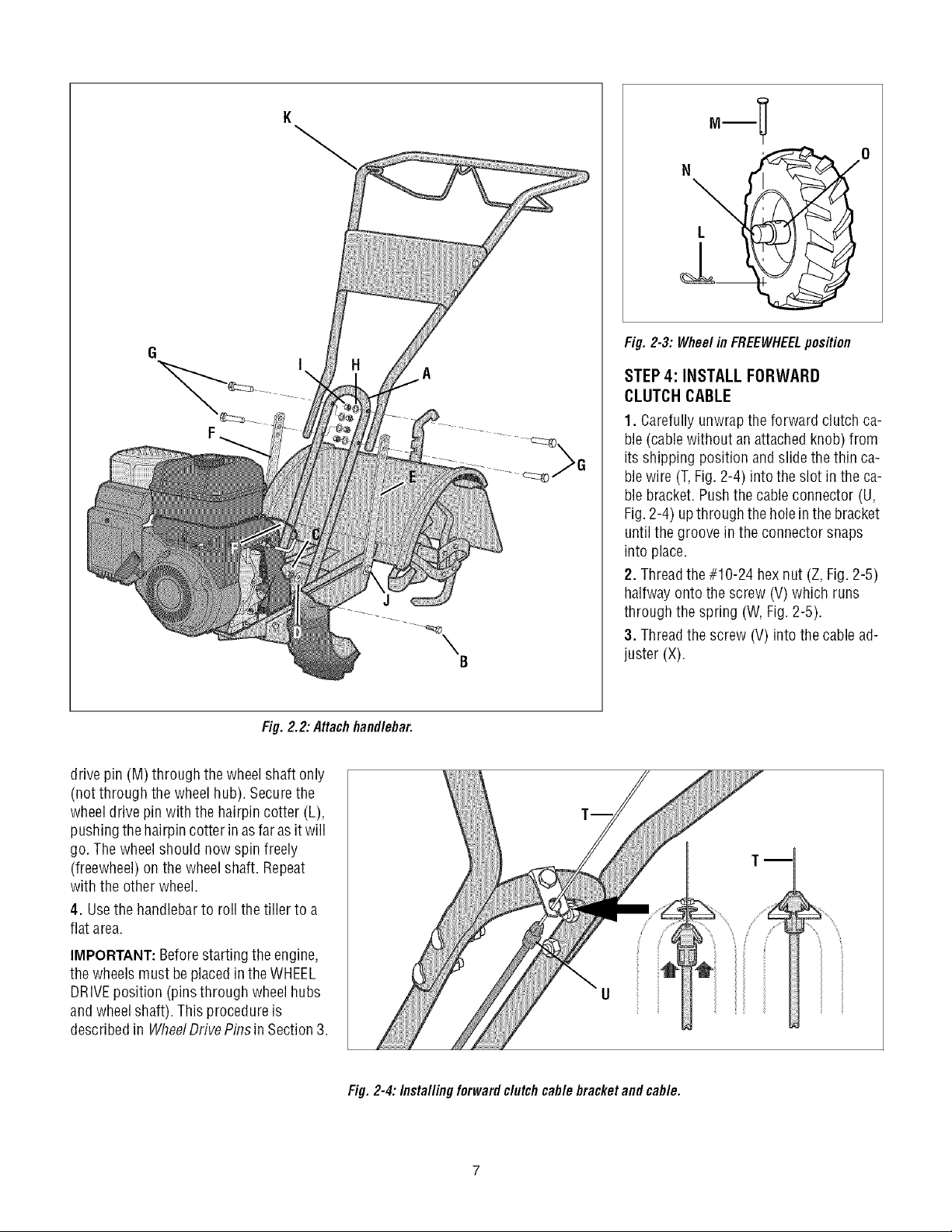
°-! °
Fig. 2-3: Wheel in FREEWHEELposition
Fig. 2.2: Attachhandlebar.
drive pin (M) through thewheelshaft only
(not through the wheel hub). Securethe
wheeldrive pin with the hairpin cotter (L),
pushingthe hairpincotter in as faras it will
go. Thewheelshould now spin freely
(freewheel) onthe wheelshaft. Repeat
with the other wheel.
4. Usethehandlebarto roll the tiller to a
flat area.
A
J
B
STEP 4: INSTALL FORWARD
CLUTCH CABLE
1. Carefully unwrapthe forward clutch ca-
ble(cablewithout an attachedknob) from
its shipping position and slide the thin ca-
blewire (T,Fig. 2-4) into the slot in the ca-
blebracket. Pushthe cableconnector (U,
Fig.2-4) upthrough the holein thebracket
untilthe groove in the connector snaps
into place.
2. Threadthe#10-24 hex nut (Z, Fig. 2-5)
halfway ontothe screw (V) which runs
through the spring (W, Fig.2-5).
3. Threadthe screw (V) into the cablead-
juster (X).
IMPORTANT: Beforestartingthe engine,
the wheels must beplacedin theWHEEL
DRIVEposition (pins through wheel hubs
andwheelshaft). This procedureis
describedin WheelDrivePinsin Section3.
Fig. 2-4: Installingforward clutchcable bracketand cable.
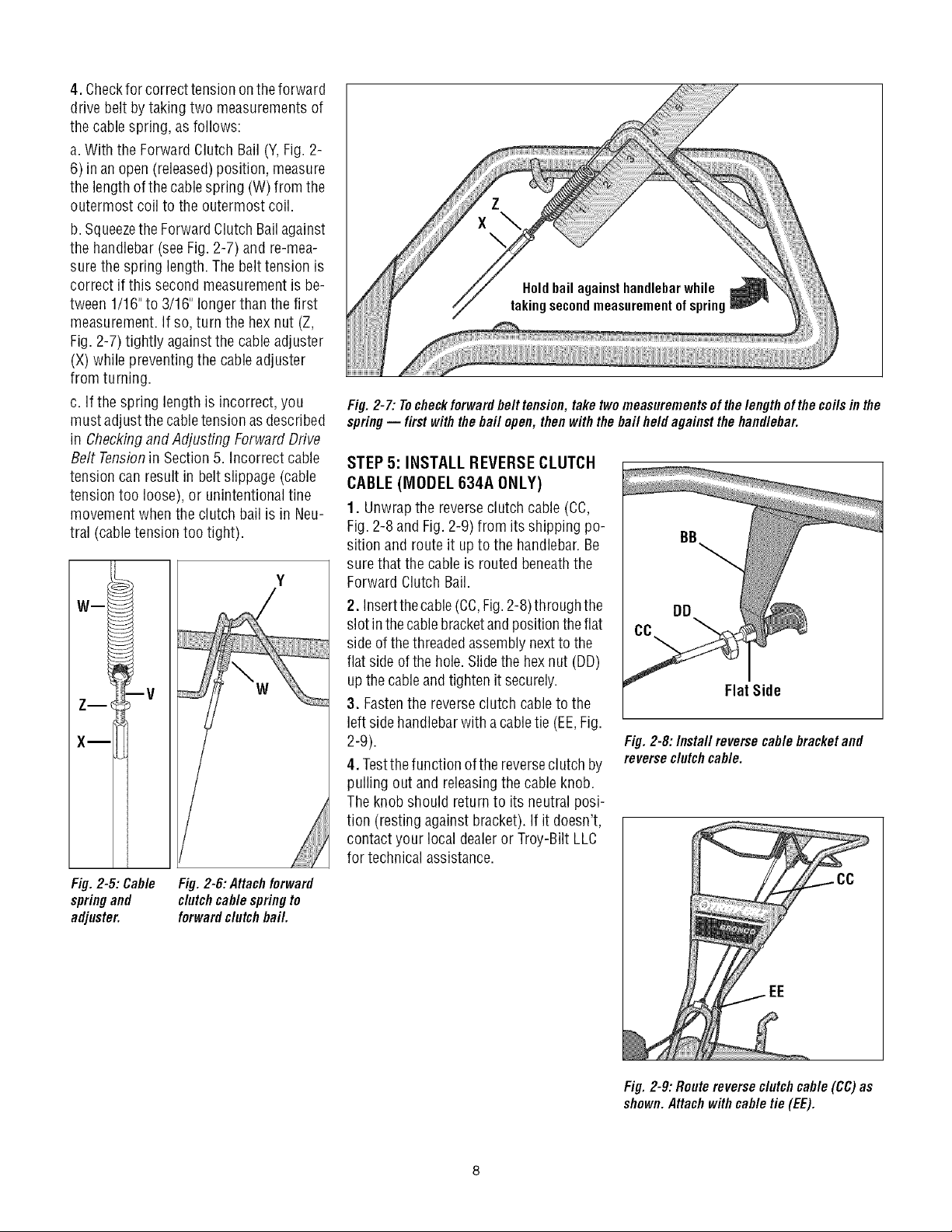
4. Checkfor correcttensionontheforward
drive belt bytaking two measurements of
the cablespring, as follows:
a.With the Forward Clutch Bail (Y,Fig. 2-
6) inanopen(released)position, measure
the length ofthe cablespring (W) from the
outermost coil to the outermost coil.
b. Squeezethe ForwardClutch Bailagainst
the handlebar(see Fig. 2-7) andre-mea-
surethe spring length. Thebelt tension is
correct if this second measurementis be-
tween 1/16"to 3/16" longer thanthe first
measurement.If so,turn the hex nut (Z,
Fig. 2-7)tightly against the cable adjuster
(X) while preventingthe cableadjuster
from turning.
c. If the spring lengthis incorrect, you
must adjustthe cabletension asdescribed
in Checkingand Adjusting Forward Drive
Belt Tensionin Section 5. Incorrect cable
tension can result in belt slippage (cable
tension too loose), or unintentional tine
movement whenthe clutch bail is in Neu-
tral (cabletension too tight).
Wm
W
iiiiiiiiiiiiiiii
Fig. 2-7: Tocheckforwardbelttension,take twomeasurementsofthelengthof the coilsinthe
spring-- first withthebail open, then withthe bail held against thehandlebar.
STEP 5: INSTALL REVERSECLUTCH
CABLE (MODEL 634A ONLY)
1. Unwrapthe reverseclutch cable (CC,
Fig.2-8 and Fig.2-9) from its shipping po-
sition and route it up to the handlebar. Be
surethat the cableis routedbeneaththe
Forward Clutch Bail.
2. Insertthecable(CC,Fig.2-8)through the
slot inthecablebracketandpositiontheflat
sideof thethreadedassemblynextto the
flat side ofthe hole.Slidethe hexnut (DD)
up thecable andtighten it securely.
Flat Side
3. Fastenthe reverseclutch cableto the
left sidehandlebarwith acabletie (EE,Fig.
2-9).
4. Testthefunction ofthe reverseclutch by
Fig. 2-8:/nsta//reverse cablebracketand
reverseclutchcable.
pulling out and releasingthe cableknob.
Theknob should return to its neutral posi-
tion (resting againstbracket).Ifit doesn't,
contact your local dealeror Troy-Bilt LLC
for technical assistance.
Fig.2-5: Cable
springand
adjuster.
Fig. 2-6: Attachforward
clutchcable springto
forwardclutch bail.
Fig. 2-9: Route reverseclutchcable (CC)as
shown.Attach withcable tie (EE).
5! 6: CHECKTRAHSMiSSiOH
OILLEVEL
Thetransmission was filledwith gearoil at
thefactory. However,you shouldcheckthe
gear oillevelatthis time to makecertain it
is correct.
IMPORTANT:Donot operatethe tiller ifthe
gear oillevel islow. Doingso will result in
severedamageto the transmission com-
ponents.
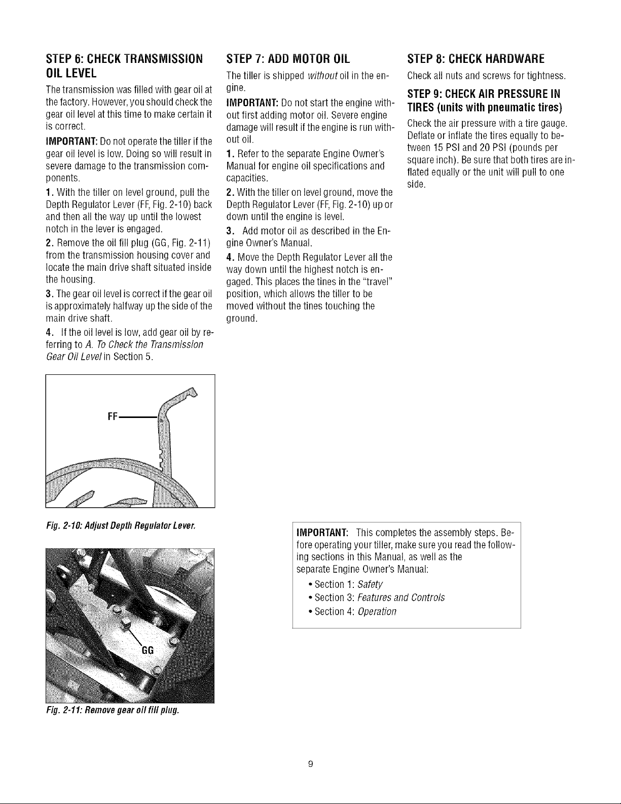
1. With the tiller on level ground, pull the
Depth RegulatorLever(FF,Fig. 2-10) back
andthen all the way up until the lowest
notch in the lever is engaged.
2. Removethe oil fill plug (GG,Fig. 2-11)
from the transmission housing cover and
locatethe maindrive shaft situated inside
the housing.
3. Thegear oilleveliscorrect ifthegear oil
isapproximately halfway upthe sideofthe
main driveshaft.
4. Ifthe oil levelislow, addgearoilby re-
ferring to A. ToCheckthe Transmission
dear 0il Levelin Section5.
I El-'/: AUU IVlUI UH UIL
Thetiller is shipped withoutoil in the en-
gine.
IMPORTANT:Donot start the engine with-
out first adding motor oil. Severeengine
damagewill result ifthe engineis run with-
out oil.
1. Refertothe separateEngineOwner's
Manualfor engine oil specifications and
capacities.
2. With thetiller on levelground, movethe
Depth RegulatorLever(FF,Fig.2-1O)up or
down until the engine is level.
3. Addmotor oil as describedin the En-
gine Owner's Manual.
4. Movethe DepthRegulator Leverall the
way down untilthe highest notch is en-
gaged.This placesthe tines in the"travel"
position, which allows the tiller to be
moved without thetines touching the
ground.
_1 El-'8: I.;HEI.;K HAHUWAHE
Checkall nuts and screws for tightness.
STEP g: CHECKAIR PRESSURE IN
TIRES (unitswithpneumatictires)
Checkthe air pressurewith a tire gauge.
Deflateor inflatethetires equally to be-
tween 15 PSIand 20 PSI (pounds per
squareinch). Besurethat both tires arein-
flated equallyor the unit will pull to one
side.
Fig. 2-10: AdjustDepth RegulatorLever.
Fig. 2-11: Removegear oil fill plug.
IMPORTANT: This completesthe assemblysteps. Be-
fore operatingyour tiller, makesureyou readthefollow-
ing sections inthis Manual,as well asthe
separateEngineOwner'sManual:
• Section1: Safety
• Section3: Featuresand Controls
• Section4: Operation
SECTION3: FEATURESANDCONTROLS
_ ARNING: Before
operatingyour machine,
carefully readand understand
all safety,controls and
operatinginstructions in this
Manual,the separateEngine
Owner's Manual,and on the
decalson the machine.
Failureto follow these
instructions can resultin
serious personalinjury.
INTRODUCTION
This Sectiondescribesthe locationand
function ofthecontrols on your tiller.Refer
to the following Section, Operationfor de-
tailed operating instructions.
Practice usingthesecontrols, with the en-
gine shut off, until you understandthe op-
eration ofthe controls and feel confident
with eachofthem.
ENGINE CONTROLS
Referto the enginemanufacturer's Engine
Owner'sManual(included in the tiller liter-
aturepackage)to identify the controls on
your engine.
IMPORTANT:Thecontrol for stopping the
engine is located onthe engine.
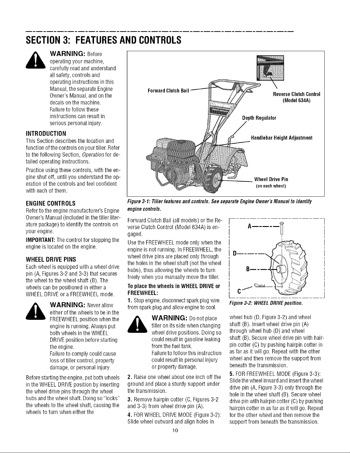
WHEEL DRIVE PINS
Eachwheel is equippedwith a wheeldrive
pin (A, Figures3-2 and 3-3) that secures
the wheelto the wheel shaft (B). The
wheelscan be positioned in either a
WHEELDRIVEor a FREEWHEELmode.
_ WARNING: Neverallow
either ofthewheelsto bein the
FREEWHEELposition whenthe
engineis running. Alwaysput
both wheelsin theWHEEL
DRIVEposition beforestarting
the engine.
Failureto comply could cause
loss of tiller control, property
damage,or personalinjury.
Beforestarting the engine,put bothwheels
in the WHEELDRIVEposition byinserting
the wheel drive pins through the wheel
hubsandthewheelshaft.Doingso "locks"
the wheels to the wheelshaft,causing the
wheelsto turn when either the
ForwardClutch
Figure3-1: Tiller features and controls.See separateEngineOwner's Manual to identify
enginecontrols.
Bail ReverseClutchControl
(Model 634A)
gulator
HandlebarHeight Adjustment
Wheel Drive Pin
(oneachwheel)
Forward ClutchBail (all models) or the Re-
verse ClutchControl (Model 634A) is en-
gaged.
Usethe FREEWHEELmode only whenthe
engineis not running, in FREEWHEEL,the
wheeldrive pins are placedonly through
the holes inthewheelshaft (notthe wheel
hubs), thus allowing the wheels to turn
freely whenyou manually movethe tiller.
ToplacethewheelsinWHEELDRIVEor
FREEWHEEL:
1. Stop engine,disconnectsparkplug wire
Figure3-2: WHEELDRIVEposition.
from sparkplug andallowengineto cool.
wheelhub (D, Figure3-2) and wheel
_ WARNING: Donotplace
tiller on its side whenchanging
wheeldrive positions. Doingso
could result in gasolineleaking
from the fuel tank.
Failureto follow this instruction
could result in personalinjury
or property damage.
2. Raiseonewheel about one inch off the
ground and placeasturdy support under
the transmission.
shaft (B). Insertwheel drive pin (A)
through wheel hub (D)and wheel
shaft (B). Securewheeldrive pin with hair-
pin cotter (C) by pushing hairpin cotter in
asfar as it will go. Repeatwith the other
wheeland then removethe support from
beneaththe transmission.
5. FORFREEWHEELMODE(Figure3-3):
Slidethewheelinwardandinsertthe wheel
drive pin (A, Figure3-3) onlythrough the
hole inthe wheel shaft (B). Securewheel
3. Removehairpin cotter (C,Figures3-2
and 3-3) from wheel drive pin (A).
4. FORWHEELDRIVEMODE(Figure3-2):
Slide wheeloutward and align holes in
lO
drivepin with hairpincotter (C)by pushing
hairpin cotter in asfar asit will go. Repeat
for the other wheelandthen removethe
support from beneaththetransmission.
 Loading...