

Troy-Bilt 208cc FLEX Operator's Manual
Safe Operation Practices • Assembly & Set-Up • Controls & Features • Operation • Maintenance • Warranty
OperatOr’s Manual
208cc FLEX™ Power Base — 23A-1AXA711
WARNING
READ AND FOLLOW ALL SAFETY RULES AND INSTRUCTIONS IN THIS MANUAL
BEFORE ATTEMPTING TO OPERATE THIS MACHINE.
FAILURE TO COMPLY WITH THESE INSTRUCTIONS MAY RESULT IN PERSONAL INJURY.
TROY-BILT LLC, P.O. BOX 361131 CLEVELAND, OHIO 44136-0019
Printed In USA
Form No. 769-10247
(January 15, 2015)

To The Owner
Thank You
Thank you for purchasing the Troy-Bilt FLEX™ Power Base. It was
carefully engineered to provide excellent performance when
properly operated and maintained.
Please read this entire manual prior to operating the equipment.
It instructs you how to safely and easily set up, operate and
maintain your machine. Please be sure that you, and any other
persons who will operate the machine, carefully follow the
recommended safety practices at all times. Failure to do so could
result in personal injury or property damage.
All information in this manual is relative to the most recent
product information available at the time of printing. Review
this manual frequently to familiarize yourself with the machine,
its features and operation. Please be aware that this Operator’s
Manual may cover a range of product specifications for various
models. Characteristics and features discussed and/or illustrated
in this manual may not be applicable to all models. We reserve
the right to change product specifications, designs and
equipment without notice and without incurring obligation.
Table of Contents
Safe Operation Practices ........................................ 3
Assembly & Set-Up .................................................. 9
Controls & Features ................................................13
Operation ................................................................15
Maintenance & Adjustment ................................ 20
1
If applicable, the power testing information used to establish
the power rating of the engine equipped on this machine can be
found at www.opei.org or the engine manufacturer’s web site.
If you have any problems or questions concerning the machine,
phone an authorized Troy-Bilt service dealer or contact us
directly. Troy-Bilt’s Customer Support telephone numbers,
website address and mailing address can be found on this page.
We want to ensure your complete satisfaction at all times.
Throughout this manual, all references to right and left side of the
machine are observed from the operating position
Troubleshooting .................................................... 27
Replacement Parts ................................................ 28
Attachments & Accessories .................................. 29
Emission Warranty ................................................ 30
Product Warranty .................................................. 32
Record Product Information
Before setting up and operating your new equipment, please
locate the model plate on the equipment and record the
information in the provided area to the right. You can locate the
model plate by standing at the operator’s position and looking
down at the rear of the power base. This information will be
necessary, should you seek technical support via our web site,
Customer Support Department, or with a local authorized service
dealer.
Model NuMber
Serial NuMber
Customer Support
Please do NOT return the machine to the retailer or dealer without first contacting the Customer Support Department.
If you have difficulty assembling this product or have any questions regarding the controls, operation, or maintenance of
this machine, you can seek help from the experts. Choose from the options below:
◊ Visit us on the web at www.troybilt.com
See How-to Maintenance and Parts Installation Videos at www.troybilt.com/tutorials
◊ Call a Customer Support Representative at (800) 828-5500 or (330) 558-7220
◊ Write to Troy-Bilt LLC • P.O. Box 361131 • Cleveland, OH • 44136-0019
2
Important Safe Operation Practices
WARNING: This symbol points out important safety instructions which, if not followed,
could endanger the personal safety and/or property of yourself and others. Read and follow
all instructions in this manual before attempting to operate this machine. Failure to comply
with these instructions may result in personal injury.
When you see this symbol. HEED ITS WARNING!
CALIFORNIA PROPOSITION 65
WARNING: Engine Exhaust, some of its constituents, and certain vehicle components
contain or emit chemicals known to State of California to cause cancer and birth defects
or other reproductive harm.
WARNING: Battery posts, terminals, and related accessories contain lead and lead
compounds, chemicals known to the State of California to cause cancer and reproductive
harm. Wash hands after handling.
DANGER: This machine was built to be operated according to the safe operation practices in
this manual. As with any type of power equipment, carelessness or error on the part of the
operator can result in serious injury. This machine is capable of amputating fingers, hands,
toes and feet and throwing objects. Failure to observe the following safety instructions could
result in serious injury or death.
2
General Operation
1. Read this operator’s manual carefully in its entirety before
attempting to assemble this machine. Read, understand,
and follow all instructions on the machine and in the
manual(s) before operation. Keep this manual in a safe
place for future and regular reference and for ordering
replacement parts.
2. Be completely familiar with the controls and the proper use
of this machine before operating it.
3. This machine is a precision piece of power equipment,
not a plaything. Therefore, exercise extreme caution at all
times. Do not use it for any other purposes other than what
it was designed for.
4. Never allow children under 14 years of age to operate this
machine. Children 14 and over should read and understand
the instructions and safe operation practices in this manual
and on the machine and should be trained and supervised
by an adult.
5. Only responsible individuals who are familiar with these
rules of safe operation should be allowed to use this
machine.
6. Thoroughly inspect the area where the equipment is to be
used. Remove all stones, sticks, wire, bones, toys and other
foreign objects, which could be tripped over or picked up
and thrown by the blade. Thrown objects can cause serious
personal injury.
7. Plan your mowing pattern to avoid discharge of material
toward roads, sidewalks, bystanders and the like. Also,
avoid discharging material against a wall or obstruction,
which may cause discharged material to ricochet back
toward the operator.
8. To help avoid blade contact or a thrown object injury,
stay in operator zone behind handles and keep children,
bystanders, helpers and pets at least 75 feet from mower
while it is in operation. Stop machine if anyone enters area.
9. Always wear safety glasses or safety goggles during
operation and while performing an adjustment or repair
to protect your eyes. Thrown objects which ricochet can
cause serious injury to the eyes.
10. Wear sturdy, rough-soled work shoes and close-fitting
slacks and shirts. Shirts and pants that cover the arms
and legs and steel-toed shoes are recommended. Never
operate this machine in bare feet, sandals, slippery or lightweight (e.g. canvas) shoes.
11. Do not put hands or feet near rotating parts or under the
cutting deck. Contact with blade can amputate fingers,
hands, toes and feet.
12. A missing or damaged discharge cover can cause blade
contact or thrown object injuries.
13. Many injuries occur as a result of the mower being pulled
over the foot during a fall caused by slipping or tripping.
Do not hold on to the mower if you are falling; release the
handle immediately.
3

14. Never pull the mower back toward you while you are
walking. If you must back the mower away from a wall or
obstruction first look down and behind to avoid tripping
and then follow these steps:
a. Step back from mower to fully extend your arms.
b. Be sure you are well balanced with sure footing.
c. Pull the mower back slowly, no more than half way
toward you.
d. Repeat these steps as needed.
15. Do not operate the mower while under the influence of
alcohol or drugs.
16. Do not engage the self-propelled mechanism on machines
so equipped while starting engine.
17. The blade control is a safety device. Never attempt to
bypass its operation. Doing so makes the safety device
inoperative and may result in personal injury through
contact with the rotating blade. The blade control must
operate easily in both directions and automatically return
to the disengaged position when released.
18. Never operate the mower in wet grass. Always be sure of
your footing. A slip and fall can cause serious personal
injury. If you feel you are losing your footing, release the
blade control handle immediately and the blade will stop
rotating within three seconds.
19. Mow only in daylight or good artificial light. Walk, never
run.
20. Stop the blade when crossing gravel drives, walks or roads.
21. If the equipment should start to vibrate abnormally, stop
the engine and check immediately for the cause. Vibration
is generally a warning of trouble.
22. Shut the engine off and wait until the blade comes to
a complete stop before removing the grass catcher or
unclogging the chute. The cutting blade continues to
rotate for a few seconds after the blade control is released.
Never place any part of the body in the blade area until you
are sure the blade has stopped rotating.
23. Never operate mower without proper trail shield,
discharge cover, grass catcher, blade control or other safety
protective devices in place and working. Never operate
mower with damaged safety devices. Failure to do so can
result in personal injury.
24. Muffler and engine become hot and can cause a burn. Do
not touch.
25. Never attempt to make a wheel or cutting height
adjustment while the engine is running.
26. Only use parts and accessories made for this machine by
the manufacturer. Failure to do so can result in personal
injury.
27. When starting engine, pull cord slowly until resistance
is felt, then pull rapidly. Rapid retraction of starter cord
(kickback) will pull hand and arm toward engine faster than
you can let go. Broken bones, fractures, bruises or sprains
could result.
28. If situations occur which are not covered in this manual, use
care and good judgement. Contact Customer Support for
assistance or the name of the nearest service dealer.
Slope Operation
Slopes are a major factor related to slip and fall accidents, which
can result in severe injury. Operation on slopes requires extra
caution. The machine is heavy and can speed up when going
downhill. Be prepared to maintain control of the machine. If you
feel uneasy on a slope, do not mow it. For your safety, use the
slope gauge included as part of this manual to measure slopes
before operating this machine on a sloped or hilly area. If the
slope is greater than 10 degrees, do not mow it.
Do:
1. Mow across the face of slopes; never up and down, to avoid
loss of control.
2. Exercise extreme caution when changing direction on slopes.
Turn uphill, not downhill.
3. Watch for holes, ruts, rocks, hidden objects, or bumps
which can cause you to slip or trip. Tall grass can hide
obstacles.
4. Always be sure of your footing. A slip and fall can cause
serious personal injury. If you feel you are losing your
balance, release the blade control handle immediately and
the blade will stop rotating within three (3) seconds.
Do Not:
1. Do not mow near drop-offs, ditches or embankments, you
could lose your footing or balance.
2. Do not mow slopes greater than 10 degrees as shown on
the slope gauge.
3. Do not mow on wet grass. Unstable footing could cause
slipping.
Children
Tragic accidents can occur if the operator is not alert to the
presence of children. Children are often attracted to the mower
and the mowing activity. They do not understand the dangers.
Never assume that children will remain where you last saw them.
1. Keep children out of the mowing area and under watchful
care of a responsible adult other than the operator.
2. Be alert and turn mower off if a child enters the area.
3. Before and while moving backwards, look behind and
down for small children.
4. Use extreme care when approaching blind corners,
doorways, shrubs, trees, or other objects that may obscure
your vision of a child who may run into the mower.
5. Keep children away from hot or running engines. They can
suffer burns from a hot muffler.
6. Never allow children under 14 years of age to operate this
machine. Children 14 and over should read and understand the
instructions and safe operation practices in this manual and on
the machine and be trained and supervised by an adult.
7. After stopping engine, remove Electric Start Push Key (if
equipped) and keep it in a safe place out of the reach of
children.
4 Section 2 — important Safe operation practiceS

Service
Safe Handling Of Gasoline:
1. To avoid personal injury or property damage use extreme
care in handling gasoline. Gasoline is extremely flammable
and the vapors are explosive. Serious personal injury can
occur when gasoline is spilled on yourself or your clothes,
which can ignite. Wash your skin and change clothes
immediately.
2. Use only an approved gasoline container.
3. Never fill containers inside a vehicle or on a truck or trailer
bed with a plastic liner. Always place containers on the
ground away from your vehicle before filling.
4. Remove gas-powered equipment from the truck or
trailer and refuel it on the ground. If this is not possible,
then refuel such equipment on a trailer with a portable
container, rather than from a gasoline dispenser nozzle.
5. Keep the nozzle in contact with the rim of the fuel tank or
container opening at all times until fueling is complete. Do
not use a nozzle lock-open device.
6. Extinguish all cigarettes, cigars, pipes and other sources
of ignition.
7. Never fuel machine indoors because flammable vapors will
accumulate in the area.
8. Never remove gas cap or add fuel while engine is hot or
running. Allow engine to cool at least two minutes before
refueling.
9. Never over fill fuel tank. Fill tank to the bottom of filler
neck, leaving space to provide for fuel expansion.
10. Replace gasoline cap and tighten securely until it clicks
indicating that it is properly tightened.
11. If gasoline is spilled, wipe it off the engine and equipment.
Move machine to another area. Wait 5 minutes before
starting engine.
12. Never store the machine or fuel container near an open
flame, spark or pilot light as on a water heater, space
heater, furnace, clothes dryer or other gas appliances.
13. To reduce fire hazard, keep machine free of grass, leaves,
or other debris build-up. Clean up oil or fuel spillage and
remove any fuel soaked debris.
14. Allow machine to cool at least 5 minutes before storing.
General Service:
1. Never run an engine indoors or in a poorly ventilated area.
Engine exhaust contains carbon monoxide, an odorless
and deadly gas.
2. Before cleaning, repairing, or inspecting, make certain the
blade and all moving parts have stopped. Disconnect the
spark plug wire and ground against the engine and remove
Electric Start Push Key (if equipped) to prevent unintended
starting.
3. Check the blade and engine mounting bolts at frequent
intervals for proper tightness. Also, visually inspect blade
for damage (e.g., bent, cracked, worn) Replace blade with
the original equipment manufacture’s (O.E.M.) blade only,
listed in this manual. “Use of parts which do not meet the
original equipment specifications may lead to improper
performance and compromise safety!”
4. Mower blades are sharp and can cut. Wrap the blade or
wear gloves, and use extra caution when servicing them.
5. Keep all nuts, bolts, and screws tight to be sure the
equipment is in safe working condition.
6. Never tamper with safety devices. Check their proper
operation regularly.
7. After striking a foreign object, stop the engine and
remove the key. Thoroughly inspect the power base and
attachment for any damage. Repair the damage before
starting and operating the equipment.
8. Never attempt to make a wheel or cutting height
adjustment while the engine is running.
9. Grass catcher components, discharge cover, and trail shield
are subject to wear and damage which could expose
moving parts or allow objects to be thrown. For safety
protection, frequently check components and replace
immediately with original equipment manufacturer’s
(O.E.M.) parts only, listed in this manual. “Use of parts which
do not meet the original equipment specifications may
lead to improper performance and compromise safety!”
10. Do not change the engine’s governor setting or over-speed
the engine. The governor controls the maximum safe
operating speed of the engine.
11. Check fuel line, tank, cap, and fittings frequently for cracks
or leaks. Replace if necessary.
12. Do not crank engine with spark plug removed.
13. Maintain or replace safety and instruction labels, as
necessar y.
14. Observe proper disposal laws and regulations. Improper
disposal of fluids and materials can harm the environment.
15. According to the Consumer Products Safety Commission
(CPSC) and the U.S. Environmental Protection Agency (EPA),
this product has an Average Useful Life of seven (7) years,
or 140 hours of operation. At the end of the Average Useful
Life have the machine inspected annually by an authorized
service dealer to ensure that all mechanical and safety
systems are working properly and not worn excessively.
Failure to do so can result in accidents, injuries or death.
Do not modify engine
To avoid serious injury or death, do not modify engine in any
way. Tampering with the governor setting can lead to a runaway
engine and cause it to operate at unsafe speeds. Never tamper
with factory setting of engine governor.
Notice Regarding Emissions
Engines which are certified to comply with California and federal
EPA emission regulations for SORE (Small Off Road Equipment)
are certified to operate on regular unleaded gasoline, and
may include the following emission control systems: Engine
Modification (EM), Oxidizing Catalyst (OC), Secondary Air
Injection (SAI) and Three Way Catalyst (TWC) if so equipped.
5Section 2 — important Safe operation practiceS
Spark Arrestor
WARNING: This machine is equipped with an
internal combustion engine and should not be used
on or near any unimproved forest-covered, brush
covered or grass-covered land unless the engine’s
exhaust system is equipped with a spark arrestor
meeting applicable local or state laws (if any).
If a spark arrestor is used, it should be maintained in effective
working order by the operator. In the State of California the
above is required by law (Section 4442 of the California Public
Resources Code). Other states may have similar laws. Federal laws
apply on federal lands.
A spark arrestor for the muffler is available through your
nearest engine authorized service dealer or contact the service
department, P.O. Box 361131 Cleveland, Ohio 44136-0019.
Safety Symbols
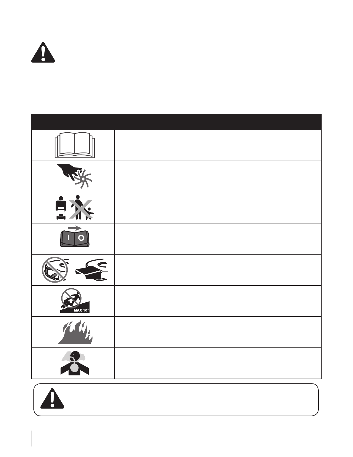
This page depicts and describes safety symbols that may appear on this product. Read, understand, and follow all instructions on the
machine before attempting to assemble and operate.
Symbol Description
READ THE OPERATOR’S MANUAL(S)
Read the power base and attachment operator’s manuals before operating.
DANGER — MOVING PARTS
Keep hands and feet away from moving parts.
ON OFF
DANGER — BYSTANDERS
Keep bystanders away. Look behind while backing.
CAUTION — STOP ENGINE
Wait for engine to come to a complete stop before removing attachment. Another means
for stopping the engine is to remove the key.
DANGER — ROTATING BLADES
Keep safety devices in place and working. If damaged, repair or replace immediately.
DANGER — SLOPES
Use extra c aution on slopes. The machine is heav y and can speed up when going downhill. Be prepared to
maintain control of the machine. To avoid loss of control, operate across slop es, not up and down. When turning,
turn uphill, not down. Do not operate on slo pes greater than 10°. Operate across slopes, never up and down.
WARNING—GASOLINE IS FLAMMABLE
Allow the engine to cool at least two minutes before refueling.
WARNING— CARBON MONOXIDE
Never run an engine indoors or in a poorly ventilated area. Engine exhaust contains carbon
monoxide, an odorless and deadly gas.
WARNING: Your Responsibility—Restrict the use of this power machine to persons who read, understand and
follow the warnings and instructions in this manual and on the machine.
6 Section 2 — important Safe operation practiceS
SAVE THESE INSTRUCTIONS!
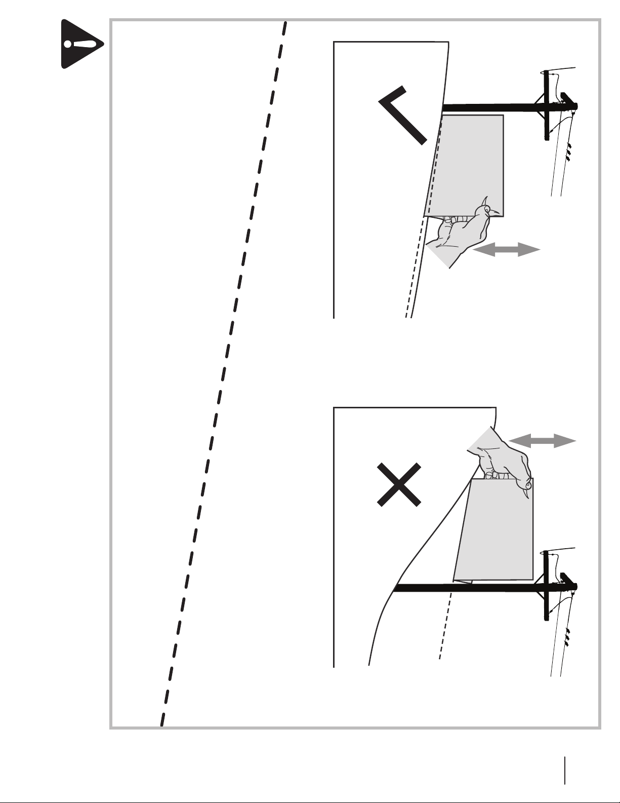
To check the slope, proceed as follows:
1. Remove this page and fold along the dashed line.
2. Locate a vertical object on or behind the slope (e.g. a pole, building, fence, tree, etc.)
3. Align either side of the slope gauge with the object (See Figure 1 and Figure 2 ).
4. Adjust gauge up or down until the left corner touches the slope (See Figure 1 and Figure 2).
5. If there is a gap below the gauge, the slope is too steep for safe operation (See Figure 2 above).
WARNING! Slopes are a major factor related to tip-over and roll-over accidents which can result in severe injury or death.
The machine is heavy and can speed up when going downhill. Be prepared to maintain control of the machine. To avoid loss
of control, operate across slopes, not up and down. When turning, turn uphill, not down. Do not operate machine on slopes
in excess of 10 degrees.
(OK) (TOO STEEP)
IF A SLOPE IS TOO STEEP FOR SAFE OPERATION!
USE THIS SLOPE GAUGE TO DETERMINE
10° dashed line
10° Slope
Slope Gauge
Figure 2Figure 1
10° Slope
7Section 2 — important Safe operation practiceS
Assembly & Set-Up
A
A
B
C
C
NOTE: All references in this manual to the left or right side
of the FLEX™ Power Base is from the operating position only.
Exceptions, if any, will be specified.
IMPORTANT: This unit is shipped WITHOUT the engine full of
oil.
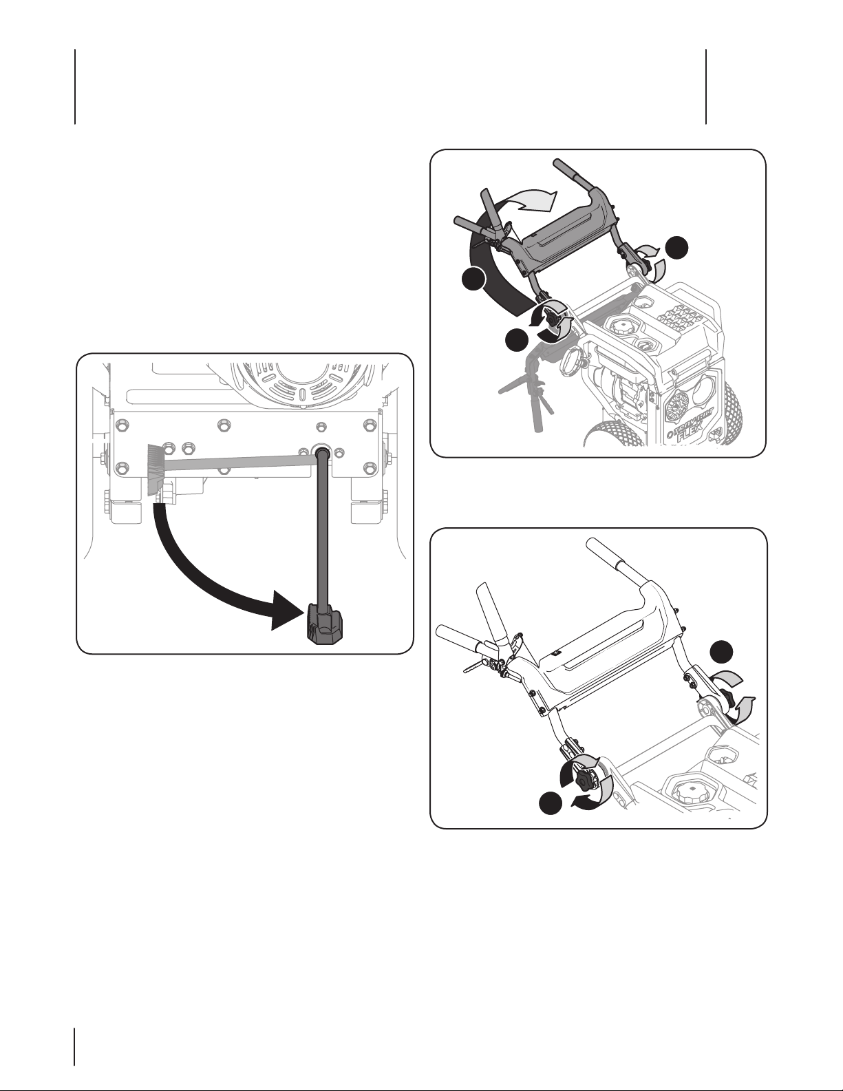
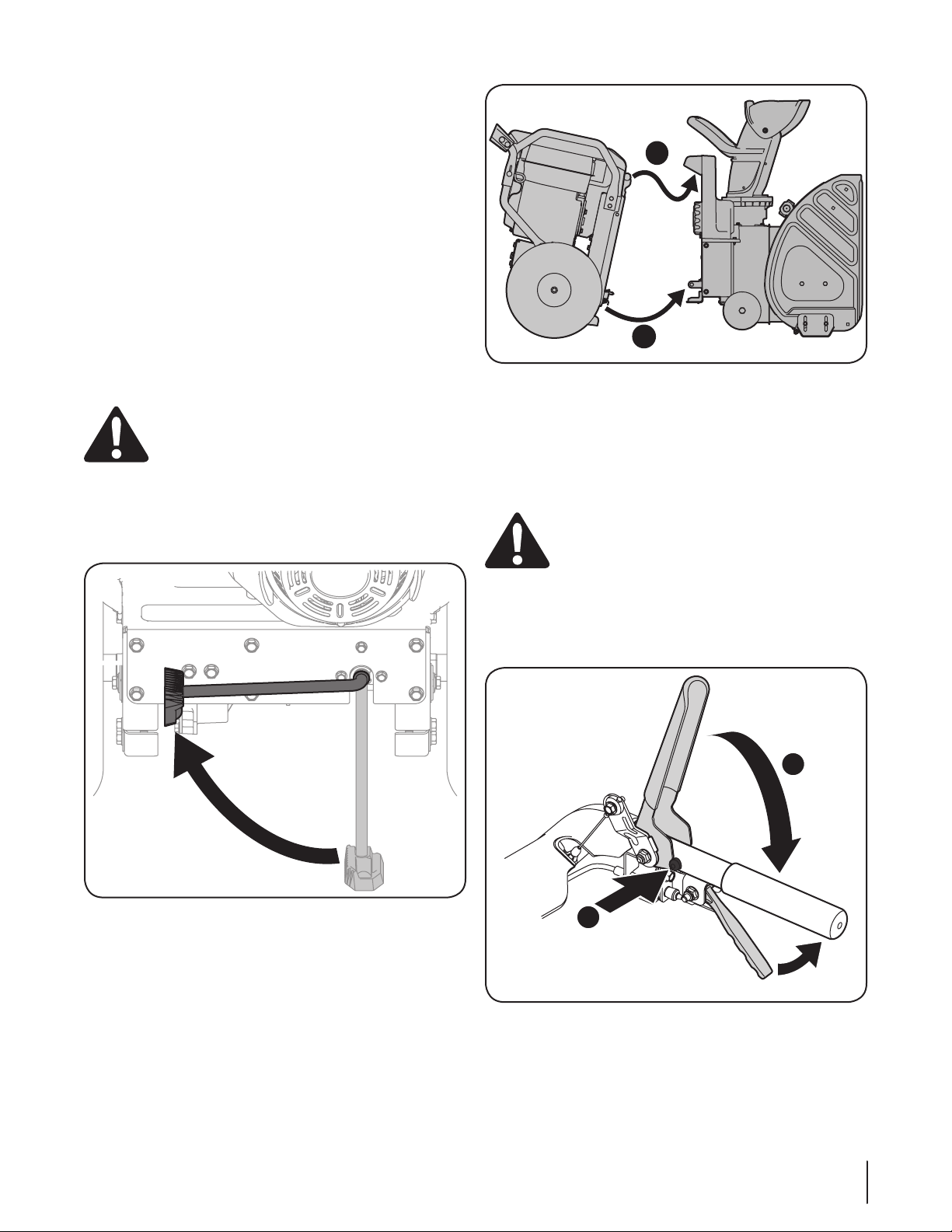
FLEX™ Power Base Parking Position
To rest the FLEX™ Power Base after unpacking it from the
shipping carton, and/or when no attachment is present, a
convenient Latch’n Lock™ kickstand has been provided on the
rear of the unit. Simply deploy the Latch’n Lock™ kickstand to
park the FLEX™ Power Base when no attachment is present. See
Figure 3-1.
3
Figure 3-2
3. Tighten the two star knobs (C) to firmly secure the upper
handle and support tubes. See Figure 3-3.
Figure 3-1
Installing and Adjusting the Handle
1. Remove any packaging material from the upper handle.
2. Loosen the star knobs (A) as shown in Figure 3-2, and pivot
the upper handle assembly upwards (B) until it reaches
the optimal operating position based on the operator’s
preference.
Note: The handle adjustment range is not infinate, and
can only be adjusted within a range. Once reaching the
stop point in either the upward or downward position, it is
imporant not to attempt for force the handle any further.
8
Figure 3-3
Note: The convenient star knobs, detailed in C of Figure 3-3, are
available for the operator to simply make a handle adjustment,
based on preference and/or application, quickly, and easily.
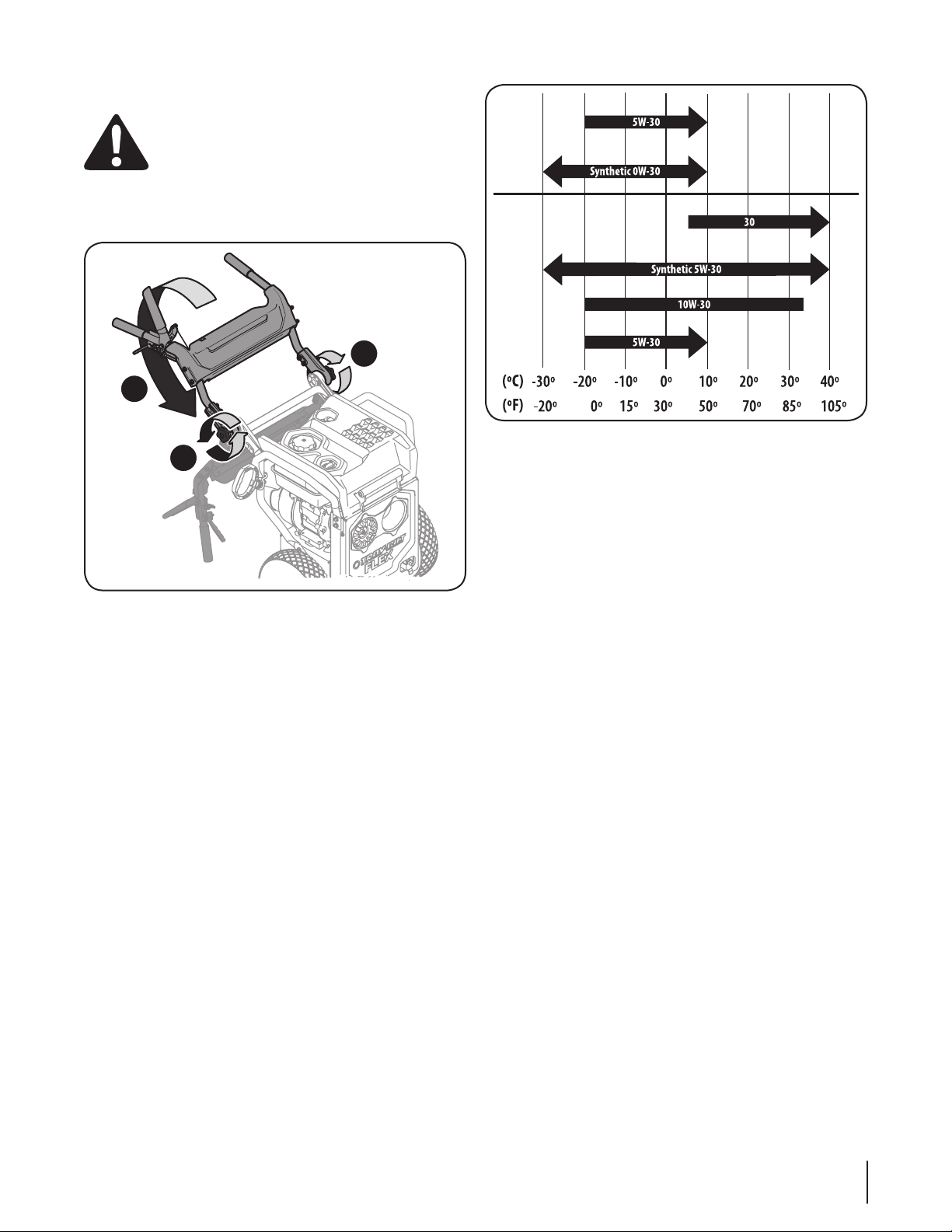
Placing Upper Handle Into the “Stowed” Position
A
A
B
Cold Weather
(Below 32 F.)
Warm Weather
(Above 32 F. )
WARNING! DO NOT attempt to fold the handle
down while the engine is hot!
1. Loosen the star knobs (A) as shown in Figure 3-4, and pivot
the upper handle assembly downwards (B) until it reaches
the bottom of it’s pivot motion.
Figure 3-5
Checking the Oil Level
NOTE: Be sure to check the oil while on a level surface with the
engine stopped.
To avoid engine damage, it is important to:
• Check oil level before each use and every 5 operating
hours when engine is warm.
• Keep oil level between “H” and “L” marks on dipstick.
Figure 3-4
2. Lightly tighten the two star knobs (C) to secure the upper
handle into the stowed position. See Figure 3-3.
Oil & Fuel Specifications
IMPORTANT: The engine is shipped without oil and gasoline
in the engine. See the following instructions for adding oil and
gasoline.
1. Remove the oil filler cap/dipstick and wipe the dipstick
2. Insert the cap/dipstick into the oil filler neck, and tighten
3. Remove the oil filler cap/dipstick. If the level is low, slowly
IMPORTANT: It is very important to check the oil level before
operating the engine and to add oil if necessary. Running the
engine with insufficient oil can cause serious engine damage and
void the engine warranty
4. Replace and tighten cap/dipstick firmly before starting
Oil Recommendations
The FLEX Power Unit is shipped with a container of oil, to be
added before its first usage. Follow the instructions below for
adding oil, and oil types thereafter.
Before starting engine, fill with motor oil, capacity is 600
ml/20 oz. Refer to the viscosity chart (Figure 3-5) for oil
recommendations. Do not over-fill. Use a 4-stroke, or an
equivalent high detergent, premium quality motor oil certified to
meet or exceed U.S. automobile manufacturer’s requirements for
service classification of a minimum level SJ (higher letter ratings
are acceptable such as SL and SM grades). Motor oil will display
this designation on the container.
NOTE: Do not use non-detergent oil or 2-stroke engine oil. It
could shorten the engine’s service life.
NOTE: To change the oil, see Changing Oil instructions in the
Maintenance Section of this manual.
See Figure 3-6.
• Be sure oil fill cap/plug is tightened securely when
checking.
clean. See Figure 3-6.
the cap until seated.
add oil until oil level registers between high (H) and low (L),
Figure 3-6.
engine.
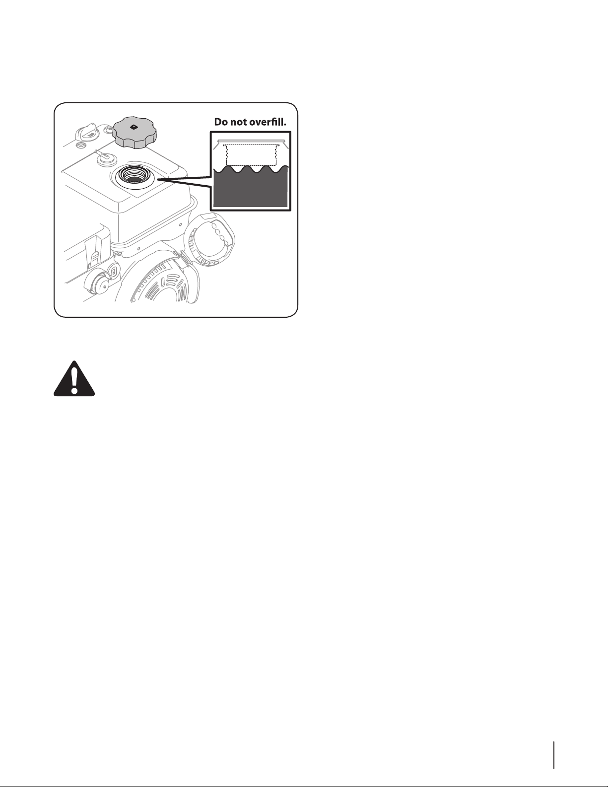
NOTE: Do not overfill. Overfilling with oil may cause
smoking, hard starting, or spark plug fouling.
NOTE: DO NOT allow oil level to fall below the “L” mark
on the dipstick. Doing so may result in equipment
malfunctions or damage.
9Section 3 — ASSembly & Set-Up
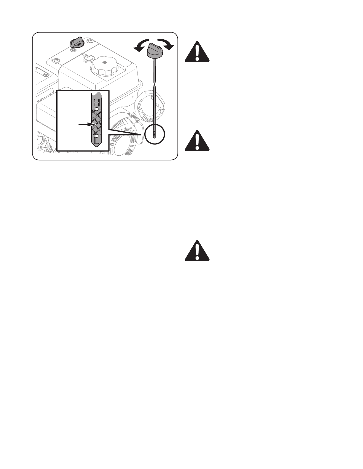
Fill
between
high
and low
marks
Figure 3-6
Adding Oil (If Needed)
IMPORTANT: This unit is shipped WITHOUT the engine full of
oil. Using the oil included with the FLEX™ Power Base, follow the
instructions below to add oil to the engine for it’s first time use.
1. Be sure the engine is upright and level.
2. Remove the oil fill cap dipstick from oil filler tube by
rotating counter-clockwise and lifting the dipstick out of
the engine. Wipe the dipstick clean with a shop rag.
3. Insert oil fill cap dipstick back into oil filler tube. On quarterturn oil fill caps, tighten by rotating the cap clockwise until
firmly seated.
4. Loosen and remove the oil fill cap dipstick from the oil
filler tube. Note the oil level, if oil reading on the dipstick
is below the “L” mark, slowly add oil to reach the “H” level.
See Figure 3-6.
5. Insert oil fill cap dipstick back into oil filler tube. Tighten by
rotating the cap clockwise until firmly seated.
6. Wipe away any spilled oil.
NOTE: To change the oil, see Changing Oil instructions in the
Maintenance Section of this manual.
Fuel Recommendations
CAUTION: Operating the engine with E15 or E85
fuel, an oil/gasoline mixture, dirty gasoline, or
gasoline over 30 days old that has not been
stabilized using a fuel additive, may result in
damage to your engine’s carburetor. Subsequent
damage would not be covered under the
manufacturer’s warranty.
Use automotive gasoline (unleaded or low leaded to minimize
combustion chamber deposits) with a minimum of 87 octane.
Gasoline with up to 10% ethanol or 15% MTBE (Methyl Tertiary
Butyl Ether) can be used. Never use an oil/gasoline mixture or
dirty gasoline. Avoid getting dirt, dust, or water in the fuel tank.
DO NOT use E15 or E85 gasoline.
WARNING! Gasoline is extremely flammable and is
explosive under certain conditions.
• Refuel in a well-ventilated area with the engine stopped.
Do not smoke or allow flames or sparks in the area where
the engine is refueled or where gasoline is stored.
• Do not overfill the fuel tank. After refueling, make sure the
tank cap is closed properly and securely.
• Be careful not to spill fuel when refueling. Spilled fuel or
fuel vapor may ignite. If any fuel is spilled, make sure the
area is dry before starting the engine.
• Avoid repeated or prolonged contact with skin or
breathing of vapor.
Adding Fuel
WARNING! An adult should fuel this engine. NEVER
allow children to refuel this engine. Gasoline (fuel)
vapors are highly flammable and can explode. Fuel
vapors can spread and be ignited by a spark or flame
many feet away from engine. To prevent injury or
death from fuel fires, follow these instructions:
• DO NOT use leaded fuel.
• Fuel must be fresh and clean. NEVER use fuel left over
from last season or stored for longer than 30 days.
• NEVER mix oil with fuel.
• DO NOT use fuel containing Methanol (Wood
Alcohol)
1. Before refueling, allow the engine to cool for two minutes.
2. Be sure engine is outdoors and in a well-ventilated area.
3. Clean area around the fuel fill cap and remove the fuel fill cap.
4. Using an approved red GASOLINE container, add fuel
slowly, being careful to avoid spilling. Fill tank until the fuel
reaches the bottom of the filler neck to allow space for fuel
expansion. Be careful not to overfill.
10 Section 3 — ASSembly & Set-Up
5. Replace the fuel cap and tighten securely. Wipe up spilled
fuel before starting engine. If fuel is spilled DO NOT start
engine. Move machine away from area of spillage. Avoid
creating any source of ignition until fuel vapors are gone.
Figure 3-7
Tire Pressure
WARNING: Under any circumstance do not exceed
manufacturer’s recommended psi. Equal tire
pressure should be maintained at all times. Excessive
pressure when seating beads may cause tire/rim
assembly to burst with force sufficient to cause
serious injury. Refer to sidewall of tire for
recommended pressure.
The tires are over-inflated for shipping purposes. Check the tire
pressure before operating the FLEX™ Power Base. Refer to the tire
side wall for tire manufacturer’s recommended psi and deflate
(or inflate) the tires as necessary. Use a manual pump or portable
electric tire inflator to prevent over-inflation. NEVER USE AN AIR
COMPRESSOR!
Note: Equal tire pressure is to be maintained at all times for
performance purposes.
11Section 3 — ASSembly & Set-Up
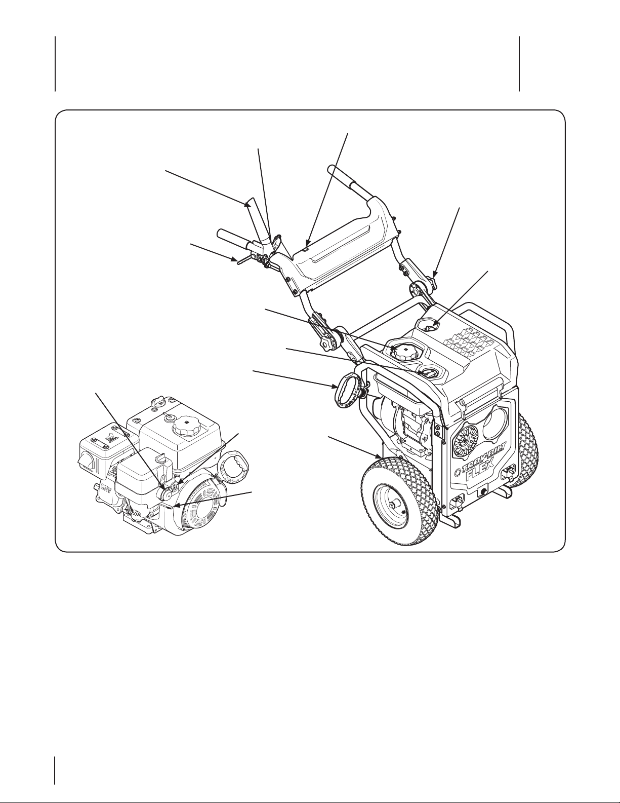
Controls & Features
Attachment Control Safety Lock
Kickstand
Cold Weather/Warm
Weather Control
Handle Adjustment Knob
On/Off Switch
Attachment Control Lever
Drive Control Lever
Fuel Cap
Oil Fill Cap
Recoil Starter
Choke
Key
Primer
4
Attachment Control Lever
The attachment control lever is for deploying power to the
various available attachments. See also Figure 4-2.
Handle Adjustment Knobs
Utilize these two knobs to adjust the height and position of the
FLEX™ Power Base’s handle assembly. Refer to Installing and
Adjusting the Handle in the Assembly and Setup Section of this
manual for specific instructions regarding adjusting the handle.
Cold Weather/Warm Weather Control
This control is utilized throughout the year. Turn the control to
Winter for Winter operation (below 32F, and Summer (above
32F for Summer operation.
Figure 4-1
Kickstand
The kickstand is utilized to hold the FLEX™ Power Base in an
upright and parked position when there is NO attachment
present. It also locks the attachment to the power base (when in
“Up” position) and unlocks the attachment when placed in the
down position.
Recoil Starter
The recoil starter employs a starter rope and handle used to pullstart the engine.
12
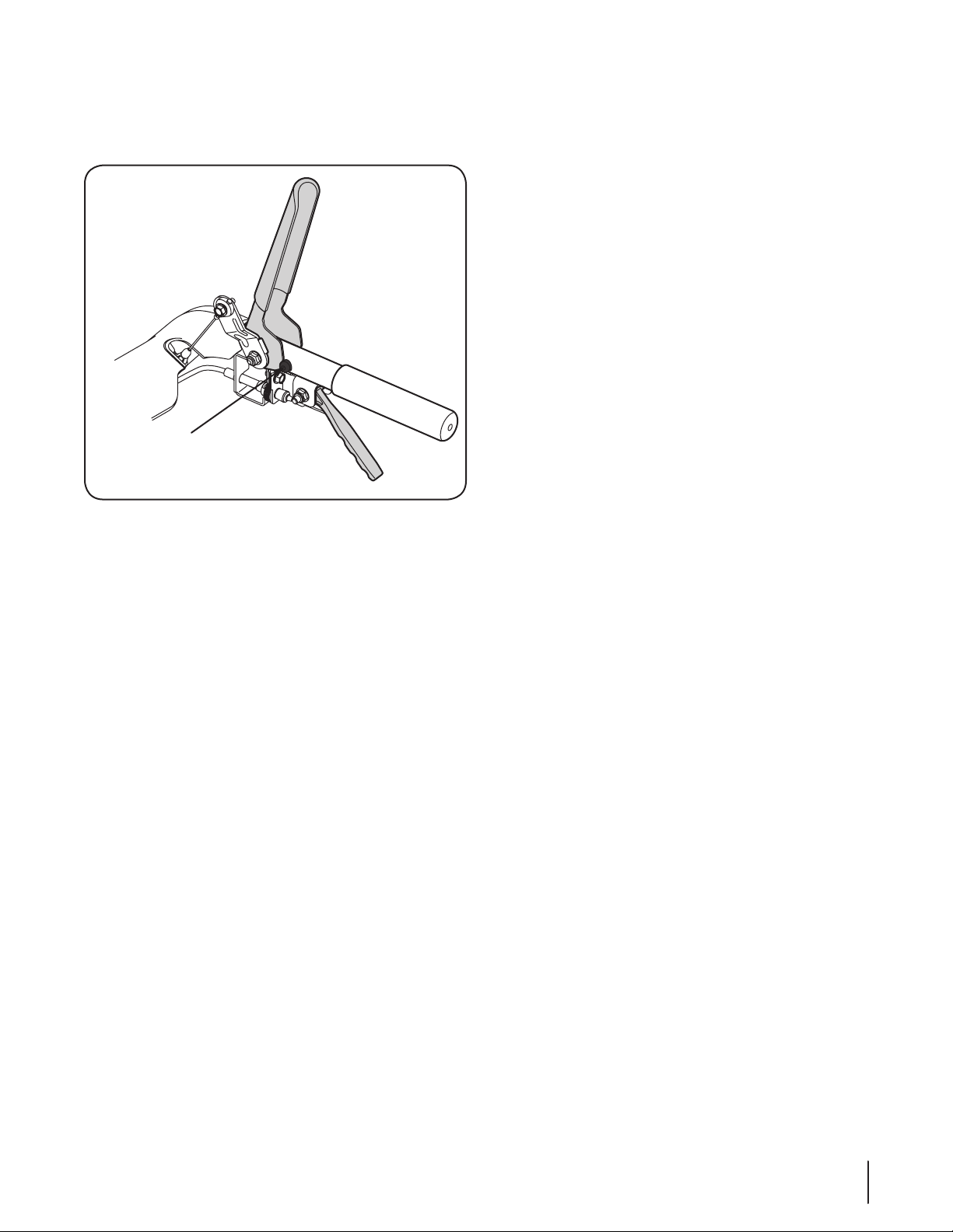
Attachment Control Safety Lock
Drive Control
Lever
Attachment Control
Safety Lock
Attachment Control
Lever
The attachment control safety lock is a red button beside the
lever that must be pressed in order to actuate the attachment
control lever. See Figure 4-2.
Figure 4-2
Engine Controls
Primer Bulb
Pressing the primer bulb forces fuel directly into the engine’s
carburetor to aid in starting a “Cold” engine.
Key
The key is a safety device. It must be fully inserted in order for the
engine to start. Remove the key when the power base is not in
use.
IMPORTANT: Do not attempt to turn the key once inserted into
the FLEX™ Power Base engine. For the engine to be in the “Run”
position, the key only need be fully inserted into the engine key
hole. Do not turn the key in an attempt to start the engine. Doing
so may cause it to break.
Choke
Activating the choke closes the choke plate on the carburetor
and aids in starting the engine.
Fuel Cap
Remove the fuel cap to fill the FLEX™ Power Base with gasoline.
Refer to the Assembly & Set-Up section of this manual for
complete fuel type and filling instructions.
Oil Fill Cap
Remove the oil fill cap to check and/or fill the FLEX™ Power
Base with engine oil. Refer to Adding Oil in the Assembly &
Set-Up section of this manual for complete fuel type and filling
instructions.
On/Off Switch
The On/Off Switch is used to remove the power to the engine,
causing the engine to come to a complete stop. Once pressed
and held, the engine will shut down. Upon releasing the On/Off
Switch, the switch will return to the ON position.
Note: The On/Off switch is a “Momentary Switch” which means
the operator must hold the switch in the OFF position until the
motor comes to a complete stop.
Note: Another way to remove power to the engine is to remove
the key by pulling it outward. DO NOT attempt to turn the key.
13Section 4 — controlS & FeatureS

Operation
ChokeRun
Fast Slow/Idle Engine Off
Primer
5
Pre-Operation Check
IMPORTANT: The engine is shipped without gasoline in the
engine. See the Set-Up Section of this manual for instructions on
adding gasoline.
IMPORTANT: Some engines are shipped with oil already in
the engine, others without oil already in the engine. It is very
important to check the oil before operating the engine and
to add if necessary. See the Set-Up Section of this manual for
instructions on checking and adding oil.
For your safety, and in order to maximize the service life of this
equipment, it is very important to check its condition before you
operate this engine. Make certain to service, correct or fix any
problem that might be identified before attempting to operate
this engine.
WARNING! Improperly maintaining this engine, or
failure to correct any problem before operation can
cause a malfunction which could result in serious
injury or even death.
Always perform a pre-operation inspection before
each operation, and correct any problem.
Before you start the engine, always check the following items:
1. Fuel Recommendations (See Set-Up Section)
2. Checking Oil Level (See Set-Up Section)
3. Air filter (if equipped) (See Maintenance Section)
4. General Overall Inspection. Check for any fluid leaks or
discharges, and loose or damaged parts.
5. Review this owner’s manual for any precautions and
procedures that should be followed before starting the
engine.
Starting the Engine
WARNING! Always keep hands and feet clear of
moving parts. Do not use a pressurized starting
fluid. Vapors are flammable.
WARNING! An adult should start the engine. Only
allow children to start the engine if an adult has
determined they are experienced and capable of
such operation.
WARNING! If you are unable to start this engine
after following instructions in this manual, contact
an authorized Troy-bilt Service Dealer. To avoid
serious burn injuries or damage to your engine, DO
NOT attempt to start or troubleshoot this engine in
any other way. For example:
• DO NOT use starting fluid.
• DO NOT spray flammable vapors into the
carburetor.
• DO NOT put flammable liquids into carburetor.
• DO NOT operate engine or pull on starter rope
with spark plug removed. Fuel can spray from
spark plug hole and ignite.
NOTE: Allow the engine to warm up for a few minutes after
starting. The engine will not develop full power until it reaches
operating temperatures.
Familiarize yourself with the engine symbols shown in Figure
5-1 before attempting to start this engine.
Figure 5-1
NOTE: The following starting instructions are for several different
types of engines. In order to locate the instructions that apply to
your engine, first determine what type of starter you have. If you
have an electric starter, see Engines With Electric Starters. If you
have a manual recoil starter, see Engines with Recoil Starters later
in this section.
The Recoil Starter
WARNING! DO NOT pull starter rope with engine
running. Doing so may VOID YOUR WARRANTY.
IMPORTANT: The FLEX™ Power Base will not start without an
attachment fully installed onto the unit.
1. To avoid carbon monoxide poisoning, be sure engine is
outdoors in a well-ventilated area.
2. Insert key into slot. Make sure it snaps into place. Do not
attempt to turn the key. See Figure 5-2.
NOTE: The engine cannot start without the key fully
inserted into the switch.
NOTE: The engine will not start without an attachment
installed onto the power base.
3. Set the unit’s On/Off switch to the “On” position.
14
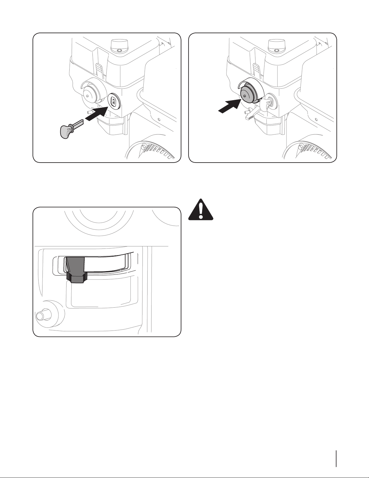
Figure 5-2
4. Be sure fuel valve, if present (see the Engine Operator’s
Manual instructions), is open.
5. Set the choke control to “FULL CHOKE” position. See Figure
5-3.
Figure 5-3
6. Hold the primer bulb in for one full second each time you
press it.
• Make sure you cover the vent hole with your
thumb.
• Prime between 3 and 5 times.
Note: Primer bulb should only be used in cold weather.
Figure 5-4
NOTE: DO NOT use the primer bulb to restart a warm
engine after a short shutdown. Doing so will flood the
engine and may result in equipment malfunction.
WARNING! When pulling the starter rope, the
rope can unexpectedly jerk back toward the engine
causing serious injury. To avoid this risk, carefully
follow these instructions:
7. Grasp the starter cord handle.
• Pull rope out slowly until you feel drag.
• Without allowing the rope to retract, continue
pulling the rope with one rapid full arm stroke.
• Return the rope slowly to the original position.
NOTE: Following the instructions listed in the steps above
avoids potential damage to the recoil mechanism.
NOTE: If the recoil starter handle is frozen and will not
operate the engine, proceed as follows:
• Pull as much rope out of the starter as possible.
• Release the starer handle and let it snap back
against the starter to break up ice; these two
steps should only be done when the starter is
frozen.
8. If the engine fails to start after 3 attempts, repeat steps 1
through 7 and try again.
9. When the Engine starts:
• Move the choke control to 1/2 “CHOKE” position
until the engine runs smoothly.
• Next, move the choke control to the NO CHOKE
position.
NOTE: If the engine starts but falters when the choke
control is moved to the “NO CHOKE” position:
15Section 5 — oper ation
• Momentarily move choke control back to “FULL
Cold Weather
Warm Weather
CHOKE” position.
• Next, move the choke control to “1/2 CHOKE”
position until engine runs smoothly.
• Finally, move the choke control to the NO
CHOKE position.
If the engine shots down after choke control is moved to “NO
CHOKE” position, repeat steps 3 through 10 to restart engine.
10. If the engine fails to start after 3 attempts in the “NO
CHOKE” position, move the choke control to “FULL CHOKE”
position and start engine.
11. If engine does not start after following steps 1 through 11,
contact your Authorized Troy-bilt Service Dealer. DO NOT
attempt to troubleshoot this engine in any other way.
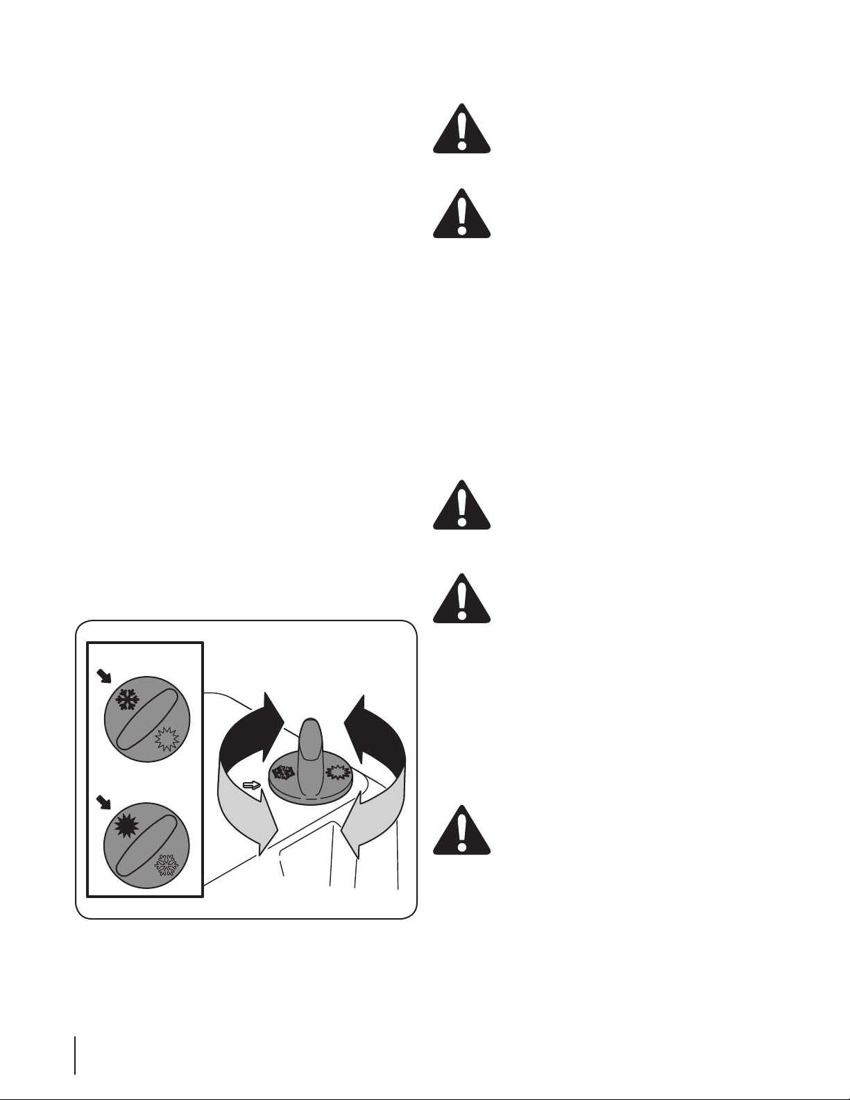
Cold Weather / Warm Weather Control
A weather control knob is available on the topside of the air filter.
This control is utilized to control the flow of air during the warm
and cold months of the year.
Note: 32 F is the general recommendation to switch
between the warm and cold setting.
To set the weather control knob:
1. In colder months, especially when operating the snow
throwing attachment, turn the knob to the position in
which the snow flake on the knob aligns with the arrow on
the air filter cover. See the top portion of the inset in Figure
5-5.
2. In warmer months, most likely when operating the
pressure washer, cutting deck, etc., place the weather
control knob in which the Sun image on the knob aligns
with the arrow on the air filter cover. See the bottom of the
inset in Figure 5-5.
Stopping the Engine & Short Term Storage
WARNING! To avoid unsupervised engine
operation, especially by children, NEVER leave the
engine unattended while running. Always turn off
the engine after use and remove the key, if
equipped.
WARNING! NEVER store the engine with fuel in the
fuel tank inside a building with potential sources of
ignition such as hot water tank and space heaters,
clothes drivers, electric motors, etc.
Stopping The Engine
1. If operating the engine in the snow or rain, run the engine
for a few minutes to help dry off any moisture.
2. Push the On/Off switch to the off position and hold until
the engine comes to a c complete stop.
Note: It is also possible to stop the engine by removing the
key, as shown in the Controls section of this manual.
3. Remove the key, if provided (see equipment Operator’s
Manual).
NOTE: Removing the key will reduce the possibility of
unauthorized starting of the engine while equipment is not
in use.
WARNING! NEVER store the engine with fuel in the
fuel tank inside a building with potential sources of
ignition such as hot water tank and space heaters,
clothes dryers, electric motors, etc.
After the Engine is Stopped
WARNING! To prevent the possible freeze-up of
engine controls, follow instructions with engine
STOPPED, listed below:
1. Wipe all snow and moisture from the engine control lever
and choke areas.
2. Move the engine choke back and forth several times and
leave in the “FULL CHOKE” position.
3. Be sure the Fuel Shut-Off Valve, if present, is off.
16 Section 5— operation
Operating Tips
NOTE: Allow the engine to warm up for a few minutes. The
engine will not develop full power until it reaches operating
temperature.
WARNING: The temperature of the muffler and
the surrounding areas may exceed 150° F. Avoid
these areas.
Figure 5-5
Connecting an Attachment
1
2
1
2
Drive Control
Lever
Note: This FLEX™ Power Base is designed to couple with a series
of attachments that will be powered by this unit. The coupling of
the various attachments are engineered with precise tolerances.
It is imperative that the operator keeps the coupling mechanisms
free from dirt and debris. Refer to the individual attachment
manuals for detailed instructions for connecting the various
attachments.
If you experience difficulty coupling these devices, possible
reasons could be dirt or debris affecting mounting pins and
latches. Clean and inspect the mounting points regularly.
The FLEX™ Power Base incorporates a special locking system,
called the Latch’n Lock™. To connect the FLEX™ Power Base to an
attachment, follow these simple steps:
1. Be sure to release the Attachment Control Lever before
attempting to connect or disconnect the FLEX™ Power
Base from any of the various attachments.
WARNING! Always be sure to release the
Attachment Control Lever before attempting to
couple or uncouple the power base from an
attachment. Failure to do so can result in damage to
your equipment, as well as possible injury resulting from
accidentally activating an attachment.
2. Put the Latch’n Lock™ kickstand into the lock (Up) position,
see Figure 5-6.
Figure 5-7
To Engage the PTO (Power Take Off)
To apply power to a FLEX attachment, follow these instructions:
NOTE: For complete operator control instructions, see the
accompanying manual included with each of the various
available attachments.
CAUTION: NEVER deploy the operator’s bail
without first putting the Latch’n Lock™ kickstand up
into its attachment lock position. Failure to do so
can cause damage to the FLEX™ Power Base.
1. Press the Attachment Control Safety Lock(red button) on
the right handle, as shown in 1 of Figure 5-8.
2. With the red button pressed in, pivot the Attachment
Control Lever downward towards the handle (2).
Figure 5-6
3. Tip the FLEX™ Power Base forward and engage the top
locking handle on the various attachment.
4. Rock the FLEX™ Power Base backwards to lock in the
bottom mounts. The operator should feel it engage and
hear an audible “click,” indicating that the attachment has
been properly connected.
Note: Try pivoting the FLEX™ Power Base forward to make
sure a connection has been established.
Figure 5-8
17Section 5 — operation
Propelling the Power Base Forward
To propel the power base forward, simply pull up on the Drive
Control Lever. To stop, simply release the lever.
Disconnecting an Attachment
Fully stop the power base engine before attempting to perform
any maintenance steps or uncoupling of the attachment.
WARNING! Always turn off the FLEX™ Power Base
engine and remove the key prior to attempting to
uncouple of the power base from the attachment.
1. Fully stop the power base, and wait for all moving parts to
come to a complete stop.
2. Release the Attachment Control Lever.
WARNING! Always be sure to release the
Attachment Control Lever before attempting to
couple or uncouple the power base from an
attachment. Failure to do so can result in damage to
your equipment.
3. With both hands on the handle grips, move the Latch’n
Lock™ kickstand into the unlock (Down) position, see
Figure 5-9.
Figure 5-9
4. Lift up on the handles, pivoting the power base forward
and move the power base backwards, away from the
attachment.
5. Park the power base utilizing the deployed Latch’n Lock™
kickstand, which should still be in the downward position.
18 Section 5— operation

Cold Weather
(Below 32 F.)
Warm Weather
(Above 32 F. )
Maintenance
Maintenance Schedule
6
Clean Engine Cooling Fins
Check Engine Oil Level
Change Engine Oil
Check Air Cleaner
Service Air Cleaner
Check Spark Plug
Replace Spark Plug
Clean Engine Shroud
Clean around Muer
Replace Fuel Filter (If equipped)
First 5 Hours
Each Use or
Every 5 Hrs.
Every Season
or 25 Hours
P
P
P P
P
P
P
P
Every Season
or 50 Hours
Every Season
or 100 Hours
P
P
P
Service Dates
Periodic inspection and adjustment of the engine is essential if
high level performance is to be maintained. Regular maintenance
will also ensure a long service life. The required service intervals
and the kind of maintenance to be performed are described
in the table above. Follow the hourly or calendar intervals,
whichever occur first. More frequent service is required when
operating in adverse conditions.
WARNING! Shut off the engine before performing
any maintenance. To prevent accidental start-up,
disconnect the spark plug boot.
NOTE: If engine must be tipped to transport equipment or to
inspect, keep the spark plug side of the engine up. Transporting
or tipping the engine spark plug side down may cause smoking,
hard starting, spark plug fouling, or oil saturation of air cleaner.
WARNING! If the engine has been running, the
muffler will be very hot. Be careful not to touch the
Oil Recommendations
Refer to the viscosity chart (Figure 6-1) for oil recommendations.
Do not over-fill. Use a 4-stroke, or an equivalent high detergent,
premium quality motor oil certified to meet or exceed
U.S. automobile manufacturer’s requirements for service
classification of a minimum level SF or SG (higher letter ratings
are acceptable such as SJ, SL and SM grades). Motor oil will
display this designation on the container.
muffler.
NOTE: Do not use non-detergent oil or 2-stroke engine oil. It
could shorten the engine’s service life.
Figure 6-1
19
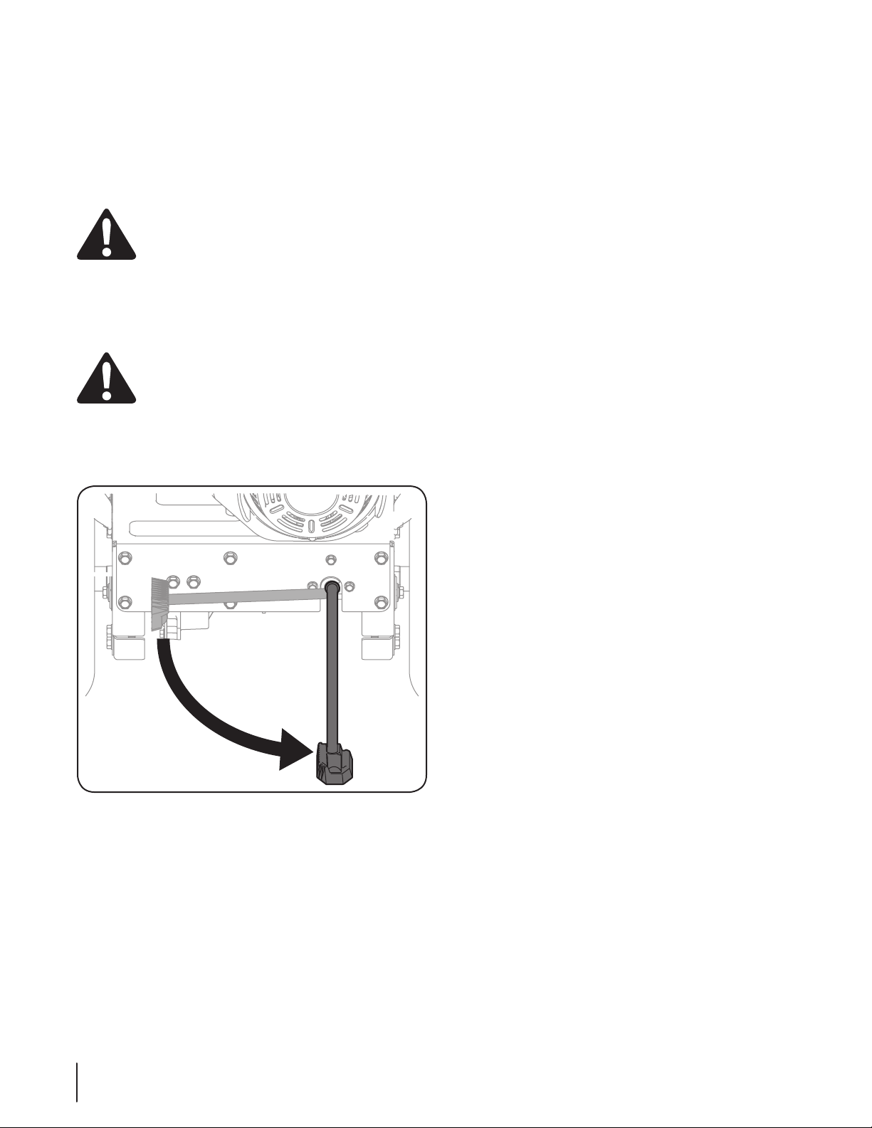
Changing Oil
To avoid engine damage, it is important to:
• Check oil level before each use and every 5 operating hours
when the engine is warm.
• Change the oil after the first 5 operating hours and every
50 operating hours thereafter. Engine should still be warm
but NOT hot from recent use.
Oil Fill Cap and Dipstick
WARNING! Before tipping engine or equipment to
drain oil, drain fuel from tank by running engine
until fuel tank is empty.
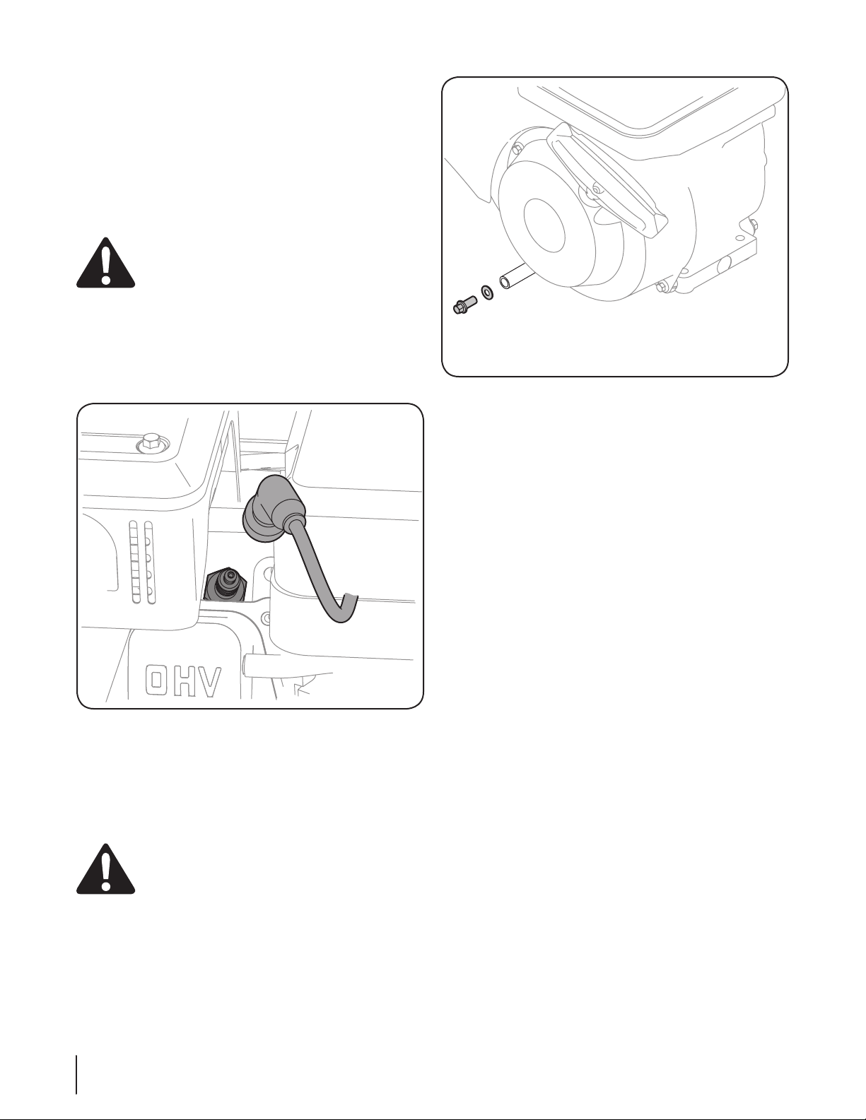
1. Carefully disconnect the spark plug wire and keep it away
from the spark plug. Refer to Figure 6-2 for spark plug
location.
• Keep the disconnected spark plug wire securely
away from the metal parts where arcing could
occur.
Figure 6-2
2. Be sure that the fuel fill cap is on and securely tightened.
3. Clean area around the oil drain plug.
4. Place an approved recyclable oil container under the oil
drain plug.
5. Remove the oil drain plug. See Figure 6-3.
WARNING! Used motor oil may cause skin cancer
if repeatedly left in contact with the skin for
prolonged periods. Although this is unlikely unless
you handle used oil on a daily basis, it is still
advisable to thoroughly wash your hands with soap
and water as soon as possible after handling used
oil.
Figure 6-3
6. Drain the oil into an approved recyclable oil container.
NOTE: Please dispose of used motor oil in a manner that is
compatible with the environment. We suggest you take it in a
sealed container to your local service station for reclamation.
Do not throw it in the trash or pour it on the ground.
7. Install the oil drain plug and tighten securely.
8. Remove the oil fill cap dipstick.
9. Fill with the recommended Oil. See Figure 6-1.
NOTE: DO NOT overfill. Doing so may result in oil carry-over
to the equipment and cause malfunction or damage.
NOTE: DO NOT allow oil level to fall below and “L” mark on
dipstick. Doing so may result in equipment malfunction or
damage.
10. Wipe away any spilled oil.
11. Check the oil level by installing the Oil Fill Cap/Dipstick.
• The Oil Fill Cap/Dipstick requires a quarter-turn
to tighten. Be sure to tighten down the cap to
check the oil level.
NOTE: See the Set-Up section earlier in this manual for
detailed instructions on checking the oil.
12. Remove the oil filler cap/dipstick. If the level is low, slowly
add oil until oil level registers between the high (H) and low
(L) mark on the dipstick. See Figure 3-6 in the Assembly &
Set-Up section for reference.
13. Repeat Steps 11 & 12 to be sure that the correct oil level has
been achieved.
14. Once the proper oil level has been confirmed, install the Oil
Fill Cap/Dipstick. Tighten securely
15. Carefully reconnect the spark plug wire to the spark plug.
NOTE: It is advisable to recheck the oil level after you have
operated the engine for a short while, and the normal engine
operating temperature has been achieved.
20 Section 6— Maintenance
 Loading...