

Page 1
Manual of Operation and Instruction
Model 5850
Gyratory Compactor
NOTE
Before using the Model 5850 Gyratory Compactor,
carefully read this manual. It is especially important to
understand the Safety Warnings on page 1–2. Keep this
manual in a safe place that is always easily accessible
during the use of the Model 5850.
Troxler Electronic Laboratories, Inc.
3008 E. Cornwallis Road P.O. Box 12057
Research Triangle Park, NC 27709 U.S.A.
Phone: 1.877.TROXLER
Outside the U.S.A.: +1.919.549.8661
Fax: +1.919.549.0761
www.troxlerlabs.com
Page 2

Troxler products are protected by U.S. and foreign patents.
Copyright 2009 – 2011
Troxler Electronic Laboratories, Inc.
All Rights Reserved
No part of this manual may be reproduced or transmitted in any
form or by any means, electronic or mechanical, including
photocopying, recording, or information storage and retrieval
systems, for any purpose without the express written permission of
Troxler Electronic Laboratories, Inc.
Bindoff is a registered trademark of Chemical Solutions, Inc.
Magnalube-G is a registered trademark of Magnalube, Inc.
Superpave is a trademark of the Strategic Highway Research
Program.
PN 116901
April 2012
Edition 2.1
ii
Page 3

TROXLER SERVICE CENTERS
Troxler Corporate Headquarters
3008 E. Cornwallis Road • P.O. Box 12057
Research Triangle Park, NC 27709
Phone: 1.877.TROXLER (1.877.876.9537)
Outside the U.S.A.: +1.919.549.8661
Fax: +1.919.549.0761
Web: www.troxlerlabs.com
Technical Support
Phone: 1.877.TROXLER (1.877.876.9537)
E-mail: TroxTechSupport@troxlerlabs.com
NORTH CAROLINA SERVICE
CENTER
3008 E. Cornwallis Road
Research Triangle Park, NC 27709
Phone: +1.919.549.8661
Fax: +1.919.549.0761
TroxTechSupport@troxlerlabs.com
FLORIDA BRANCH OFFICE &
SERVICE CENTER
2376 Forsyth Road
Orlando, FL 32807
Phone: +1.407.681.4221
Fax: +1.407.681.3188
TroxTechSupport@troxlerlabs.com
MIDWESTERN BRANCH
OFFICE & SERVICE CENTER
1430 Brook Drive
Downers Grove, IL 60515
Phone: +1.630.261.9304
Fax: +1.630.261.9341
TroxTechSupport@troxlerlabs.com
WESTERN BRANCH OFFICE &
SERVICE CENTER
11300 Sanders Drive, Suite 7
Rancho Cordova, CA 95742
Phone: +1.916.631.0234
Fax: +1.916.631.0541
TroxTechSupport@troxlerlabs.com
SOUTHWESTERN BRANCH
OFFICE & SERVICE CENTER
2016 East Randol Mill Road
Suite 406
Arlington, TX 76011
Phone: +1.817.275.0571
Fax: +1.817.275.8562
TroxTechSupport@troxlerlabs.com
TROXLER EUROPE &
SERVICE CENTER
Troxler Electronics GmbH
Gilchinger Strasse 33
D.82239 Alling nr.
Munich, Germany
Phone: ++ 49.8141.71063
Fax: ++49.8141.80731
troxler@t-online.de
TROXLER ELECTRONIC TECHNOLOGIES (ZHANGJIAGANG)
1F, Building G, No. 1 Guotai North Road
ZJG, China, 215600
Phone: 0086.512.56793702 Fax: 0086.512.56793701
kjin@troxlerlabs.cn
To locate an independent, Troxler-authorized service
partner near you, call 1.877.TROXLER (1.877.876.9537).
Model 5850 iii
NOTE
Page 4

ABOUT THIS MANUAL
The Model 5850 Manual of Operation and Instruction provides
detailed information about the compactor. The manual includes
product safety information, as well as instructions for the proper
installation and use of the compactor.
This manual is organized as follows:
Chapter 1, Introduction to the Model 5850 – Provides
information on the safe use of the compactor; a brief overview
of the compactor and its features; a list of parts and accessories;
and instructions for unpacking and inspection.
Chapter 2, Setup and Operation – Describes the compactor
keypad, and provides instructions for setting up, starting, and
operating the compactor.
Chapter 3, Setup Menu – Provides a detailed description of the
options available from the compactor’s Setup menu.
Chapter 4, Calibration and Verification – Includes instructions
for calibrating the compactor and verifying its calibration.
Chapter 5, Special Functions – Describes the functions available
from the compactor’s Special menu.
Appendix A, Troubleshooting and Service – Provides
maintenance and service information, as well as instructions on
basic troubleshooting.
Appendix B, Menu Map – Shows a map of the compactor’s Setup
menu.
Appendix C, Specifications – Contains the environmental,
performance, electrical, and mechanical specifications of the
compactor.
iv
Page 5

HOW TO USE THIS MANUAL
Congratulations on the purchase of the Model 5850 Gyratory
Compactor.
The Model 5850 Manual of Operation and Instruction contains
information on safely using this unit. Also included in this manual
are safety warnings, basic parameter setup, system troubleshooting,
and general maintenance.
Do not attempt to operate the Model 5850 before reading this
manual and the safety warnings posted on the unit. Troxler stresses
that the user is solely responsible for ensuring the safe use of the
Model 5850. The manufacturer, its subsidiary, representatives, and
distributors cannot assume responsibility for any mishaps, damage,
or personal injury that may occur from failure to observe the safety
warnings in this manual and posted on the unit.
Model 5850 v
Page 6
CONVENTIONS USED IN THIS MANUAL
Throughout this manual, symbols and special formatting are used to
reveal the purpose of the text as follows:
WARNING
Warnings indicate conditions or procedures that, if
not followed correctly, may cause personal injury.
CAUTION
Cautions indicate conditions or procedures that, if not
followed correctly, may cause equipment damage.
NOTE
Notes indicate important information that must be read
to ensure proper operation.
KEY Angle brackets and a different typestyle indicate a
key or character (number or letter) to press on the
compactor keypad. For example, “Press START”
means to press the key labeled START.
DISPLAY A different typestyle is used in text to indicate
information or messages displayed on the
compactor.
DISPLAY- Typestyle and
shading used to
simulate the control
panel display
Numbers indicate a procedure with multiple steps.
11..
Diamonds indicate a list of things needed (such as
equipment) or things to know.
Triangles indicate that more than one option is
available. Carefully select the option that applies.
vi
Page 7

TABLE OF CONTENTS
CHAPTER 1. INTRODUCTION TO THE MODEL 5850
Safety Warnings ............................................................................ 1–2
Cautions and Warnings ................................................................. 1–3
Introduction ................................................................................... 1–4
Parts and Accessories.................................................................... 1–8
Inspection ...................................................................................... 1–9
Unpacking ................................................................................... 1–10
Site Selection .............................................................................. 1–11
Assembly .................................................................................... 1–12
CHAPTER 2. SETUP AND OPERATION
Control Panel ................................................................................ 2–2
Turning the System On ................................................................. 2–4
Compacting a Specimen ............................................................... 2–7
Cleaning and Lubricating.............................................................. 2–8
Preparing a Specimen ................................................................. 2–10
Compacting the Specimen .......................................................... 2–12
Shear Options & Performance Tests ........................................... 2–13
CHAPTER 3. SETUP MENU
Setup Menu ................................................................................... 3–2
View Settings ................................................................................ 3–3
Change Settings ............................................................................ 3–4
Home Position ............................................................................ 3–13
Calibration .................................................................................. 3–13
Special......................................................................................... 3–13
CHAPTER 4. CALIBRATION
Angle Verification ........................................................................ 4–3
Calibration .................................................................................... 4–5
Model 5850 vii
Page 8

CHAPTER 5. SPECIAL FUNCTIONS
Special Menu ................................................................................. 5–2
Clock/Calendar .............................................................................. 5–3
Erase Records ................................................................................ 5–6
Reset Software ............................................................................... 5–7
APPENDIX A. TROUBLESHOOTIGN AND SERVICE
Troubleshooting.............................................................................A-2
General Maintenance Schedule .....................................................A-4
Replacing the Batteries ..................................................................A-7
Replacement Parts .........................................................................A-8
Returning Parts for Service ...........................................................A-9
APPENDIX B. MENU MAP
Menu Map Description .................................................................. B-2
APPENDIX C. SPECIFICATIONS
Environmental Conditions ............................................................. C-2
Electrical Specifications ................................................................ C-3
Mechanical Specifications ............................................................. C-4
INDEX
WARRANTY
viii
Page 9

LIST OF FIGURES
Figure Title Page
Figure 1–1. Model 5850 Gyratory Compactor ............................. 1–7
Figure 1–2. Hydraulic Reservoir ................................................ 1–12
Figure 1–3. Proper Reservoir Fill Level ..................................... 1–13
Figure 1–4. Place a Funnel in Reservoir Fill Tube ..................... 1–13
Figure 2–1. Model 5850 Control Panel Layout ............................ 2–3
Figure 2–2. Compaction Chamber ................................................ 2–9
Figure 2–3. Loading the Mold .................................................... 2–11
Figure 3–1. Sample Height Versus Gyration Table .................... 3–12
Figure 4–1. Aligning the Internal Angle Device Probes ............... 4–3
Figure 4–2. Puck Centered on Lower Carriage Plate ................... 4–7
Figure 4–3. Routing Load Cell Cables ......................................... 4–8
Figure A–1. Hydraulic Filter Bypass Indicator............................. A-6
Figure B–1. Model 5850 Menu Map ............................................ B-3
Model 5850 ix
Page 10

LIST OF TABLES
Table Title Page
2–1 Control Panel Keys and Button ................................. 2–2
x
Page 11

1. INTRODUCTION
CHAPTER 1
INTRODUCTION TO THE MODEL 5850
The Model 5850 is Troxler’s newest Superpave™ Gyratory
Compactor and the most advanced, easiest to use gyratory
compactor on the market today. This chapter introduces the Model
5850 and provides information on operating the compactor safely.
This chapter also includes a list of parts and accessories, and
instructions for unpacking and inspecting the system.
CONTENTS
Safety Warnings ............................................................................ 1–2
Cautions and Warnings ................................................................. 1–3
Introduction ................................................................................... 1–4
Safe Operation ........................................................................ 1–4
Ease of Operation ................................................................... 1–5
Performance Tests and Shear Options .................................. 2–13
Care and Maintenance ............................................................ 1–6
Parts and Accessories.................................................................... 1–7
Inspection ...................................................................................... 1–9
Unpacking ................................................................................... 1–10
Site Selection .............................................................................. 1–11
Assembly .................................................................................... 1–12
Model 5850 1–1
Page 12

SAFETY WARNINGS
The Troxler Model 5850 is a safe, durable gyratory compactor.
Troxler cannot anticipate every example of improper or
unauthorized use of this unit that may lead to malfunction or
accident. Thus, if a particular use is not specifically mentioned in
this manual as authorized, then consult Troxler about the alternate
use. Otherwise, it is assumed that the use is unauthorized and
improper.
To ensure minimal operator risk, Troxler recommends the following
safety precautions:
Wear safety glasses when preparing an asphalt specimen.
Always wear heat-resistant gloves when handling any hot
substance.
When moving the mold, grasp it firmly on either side under the
top flange.
Remove all objects, except the mold and asphalt specimen, from
the compaction chamber before pressing the START key.
Do not operate the compactor with the chamber door or any
panels removed.
Do not wear loose clothing or jewelry when operating the
compactor.
Keep hands away from the gyratory compactor when the unit is
in motion.
With the service panels removed, the gyratory compactor poses
an electrical hazard. Unplug the gyratory compactor before
removing the panels.
1–2
Page 13
1. INTRODUCTION
CAUTIONS AND WARNINGS
Identification of Interconnects:
Lower Left Side of Compactor
Connection for 100 – 240 VAC, 50/60 Hz power to the
compactor
Upper Left Side of Compactor
9-pin RS-232C serial interface for connecting the
compactor to a computer or serial device
USB port for connecting the compactor to a USB
printer or memory device
Model 5850 1–3
Page 14
INTRODUCTION
The Troxler Model 5850 Superpave Gyratory Compactor
provides compaction of asphalt specimens at a given pressure,
angle, and number of gyrations. The Model 5850 meets or exceeds
all Federal Highway Administration (FHWA) Superpave
specifications.
The Model 5850 Gyratory Compactor provides safe, reliable
gyratory compaction of asphalt specimens using a compaction
pressure and gyration angle selected by the operator. The method of
specimen compaction is crucial to creating asphalt specimens that
behave similar to asphalt used in construction and in obtaining
meaningful test results.
Building upon the successes of Troxler’s Model 4140 and 4141
Gyratory Compactors, the Model 5850 has been completely
redesigned with improved electronics, a robust compaction system,
and software-adjustable angle of gyration. The durable Model 5850
will consistently stand up to the rigors of any asphalt lab.
SAFE OPERATION
For operator safety, all moving parts are covered and cannot be
physically accessed during compaction. An interlock switch
prevents the gyratory compactor from operating with the
compaction chamber door open. The red EMERGENCY safety
switch located at the bottom of the control panel stops all moving
parts.
WARNING
Do not operate the Model 5850 Gyratory Compactor
with the chamber door or any panels removed.
1–4
Page 15

1. INTRODUCTION
EASE OF OPERATION
The Model 5850 is calibrated and ready to use upon arrival. The
unit will compact asphalt samples to a specific height or a specific
number of gyrations, as selected by the operator. The angle of
gyration is recorded with every gyration, assuring angle stability.
As selected by the operator, the Model 5850 provides a compaction
pressure of 200 to 1000 kPa and an angle of gyration between 0.00
and 1.50 degrees. Angle and pressure adjustments can be performed
quickly and easily using the keypad.
For ease of operation, the Model 5850 provides a fully automatic
method of compaction. The Model 5850 compacts an asphalt
specimen at the touch of a single key.
NOTE
Do not attempt to operate the Model 5850 before
reading this manual and the safety warnings posted on
the unit. Troxler stresses that the operator is solely
responsible for ensuring the safe use of the Model 5850.
The manufacturer, its subsidiaries, distributors, or
representatives cannot assume responsibility for any
mishaps, damage, or personal injury which may occur
from failure to observe the safety warnings in this
manual and posted on the unit.
The Model 5850 can be equipped with 150-mm, 100-mm, or 4-inch
diameter molds, and can compact specimens with heights of up to
185 mm.
The Model 5850 features USB and serial ports for transferring data
to USB or serial devices. The operator may choose to automatically
send the compaction data to a computer, printer, or USB device
upon completion of a compaction cycle.
NOTE
A list of USB memory devices and printers that are
compatible with the Model 5850 Gyratory Compactor is
available on the 5850 product page of the Troxler
website (www.troxlerlabs.com).
Model 5850 1–5
Page 16

The Model 5850 also provides storage for and allows manual
printing of the last 20 compacted specimens. All output is in SI units
as described in American Society of Testing and Materials (ASTM)
SI10, Standard for Use of the International System of Units (SI):
The Modern Metric System.
CARE AND MAINTENANCE
The Model 5850 requires little maintenance. To reduce the effects
of gyration on moving parts, the gyratory compactor requires
regular cleaning and lubrication. For a schedule of machine
maintenance, refer to Appendix A.
1–6
Page 17
1. INTRODUCTION
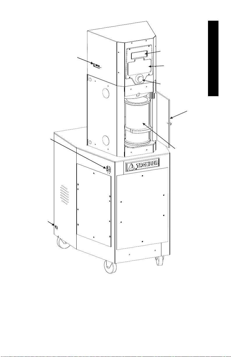
CHAMBER
DOOR
(IN OPEN
POSITION)
KEYPAD
DISPLAY
EMERGENCY
STOP SWITCH
SERIAL & USB
PORTS
AC POWER
INLET
POWER
SWITCH
MOLD
Figure 1–1. Model 5850 Gyratory Compactor
Model 5850 1–7
Page 18

PARTS AND ACCESSORIES
The Model 5850 includes the electrical and mechanical parts
required to continuously compact hot-mix asphalt. Use Figure 1–1
to locate and identify the following parts:
The power switch is located on the left side of the compactor.
The emergency stop switch stops all machine movement.
The keypad and display provide the interface.
The mold with the lower puck inserted receives the asphalt for
making specimens. Troxler offers molds with inside diameters
of 150 mm, 100 mm, and 4 inches. (Part numbers 116066 and
116069)
The USB and serial ports enable the operator to print or
download data to a USB or serial device.
The USB cable (not shown) connects the compactor to the
printer or other USB device. (Part number 110697)
The serial cable (not shown) connects the compactor to a serial
device, such as a computer. (Part number 106514)
The gravity extruder (not shown) is used to remove a
compacted specimen from the mold. (Part number 110665)
The height standard assembly (not shown) is used to calibrate
the specimen height. (Part number 106989)
The Model 5850 Manual of Operation and Instruction (not
shown) provides the operating instructions for the compactor.
The printer (not shown) allows the operator to print data. (Part
number 116220)
The specimen papers (not shown) prevent the asphalt specimen
from sticking to the puck and ram head. (Part number 106953)
The optional Pressure Verification Kit (not shown) allows the
operator to verify the pressure calibration. The pressure is
initially calibrated at the factory. (Part number 108706)
1–8
Page 19

1. INTRODUCTION
INSPECTION
Upon receiving the Model 5850 Gyratory Compactor from the
factory, perform a complete inspection and inventory as described
below.
Check to see that the following are included:
Model 5850 Gyratory Compactor
Mold
Power cord
Height standard assembly
Specimen papers (500 per package)
Printer
USB cable
Serial cable
Manual of Operation and Instruction
Gravity extruder
Inspect each part for damage that may have occurred during
shipment. If any parts or accessories appear damaged, notify the
carrier and your Troxler representative immediately.
Model 5850 1–9
Page 20
UNPACKING
WARNING
The Model 5850 Gyratory Compactor weighs
approximately 227 kg (500 lb). To prevent personal
injury or equipment damage, exercise care while
unpacking and lifting the unit.
NOTE
Troxler recommends that all packaging material be
saved. It may be reused to pack the compactor for
shipping.
To remove the shipping carton from the top of the unit, cut each
11..
side of the carton approximately 2 inches above the pallet. Lift
the carton up and off the unit.
Remove the metal strap and bolts that secure the compactor
22..
to the pallet.
Remove the two brackets that secure the front casters in
33..
place. The compactor is now free to roll on the pallet.
WARNING
To prevent personal injury or equipment damage,
do not tip the compactor while lifting it from the
pallet.
Using a forklift, lift the compactor from the pallet.
44..
CAUTION
When using a forklift, lift the compactor from the side to
prevent equipment damage.
1–10
Page 21

1. INTRODUCTION
SITE SELECTION
After unpacking and inspecting the compactor as described in the
previous sections, select a suitable site for installation. Apply the
following criteria in selecting the installation site:
Place the compactor on a flat, level location.
Locate the compactor no more than 1.2 m (4 ft) from the
required electrical power source (see Appendix C). Ensure that
the distance does not place stress on the power cord. The power
source must be wired by a qualified electrician.
The power switch is located on the left side panel, as shown in
Figure 1–1. Ensure that the placement of the compactor
provides easy access to the power switch.
Model 5850 1–11
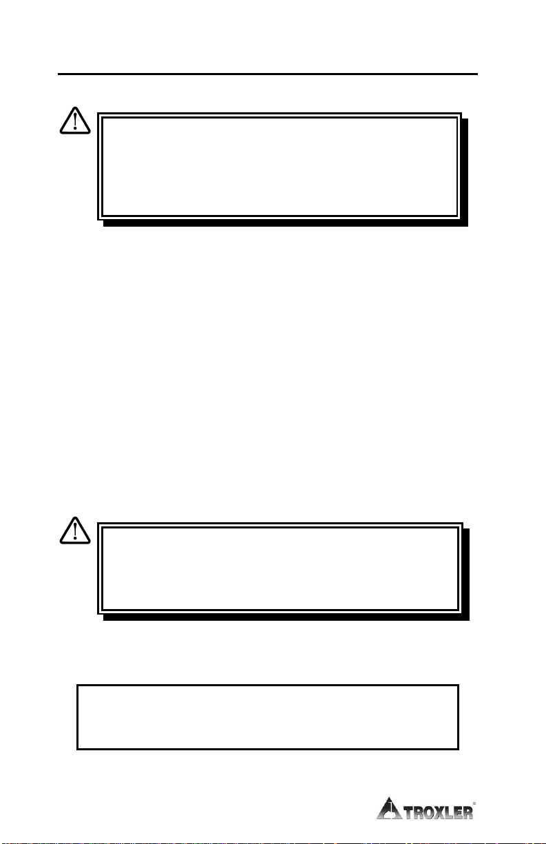
Page 22
RESERVOIR
FILL CAP
FILL LEVEL
SIGHT GLASS
ASSEMBLY
The hydraulic reservoir is filled with a premium quality, light
11..
grade (ISO VG 32, SAE 10) hydraulic oil prior to shipping.
Before using the compactor, check the oil level as follows:
Remove the rear service panel from the compactor.
aa..
Locate the fill level sight glass as shown in Figure 1–2.
bb..
NOTE
Use only a light grade (ISO VG 32, SAE 10, Troxler part
number 018203) hydraulic oil to fill the hydraulic
reservoir.
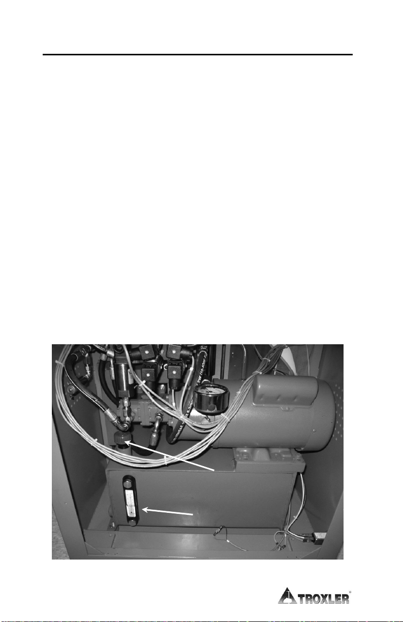
Ensure that the oil level is at the 30-degree mark on the sight
22..
glass, as shown in Figure 1–3. If oil is needed:
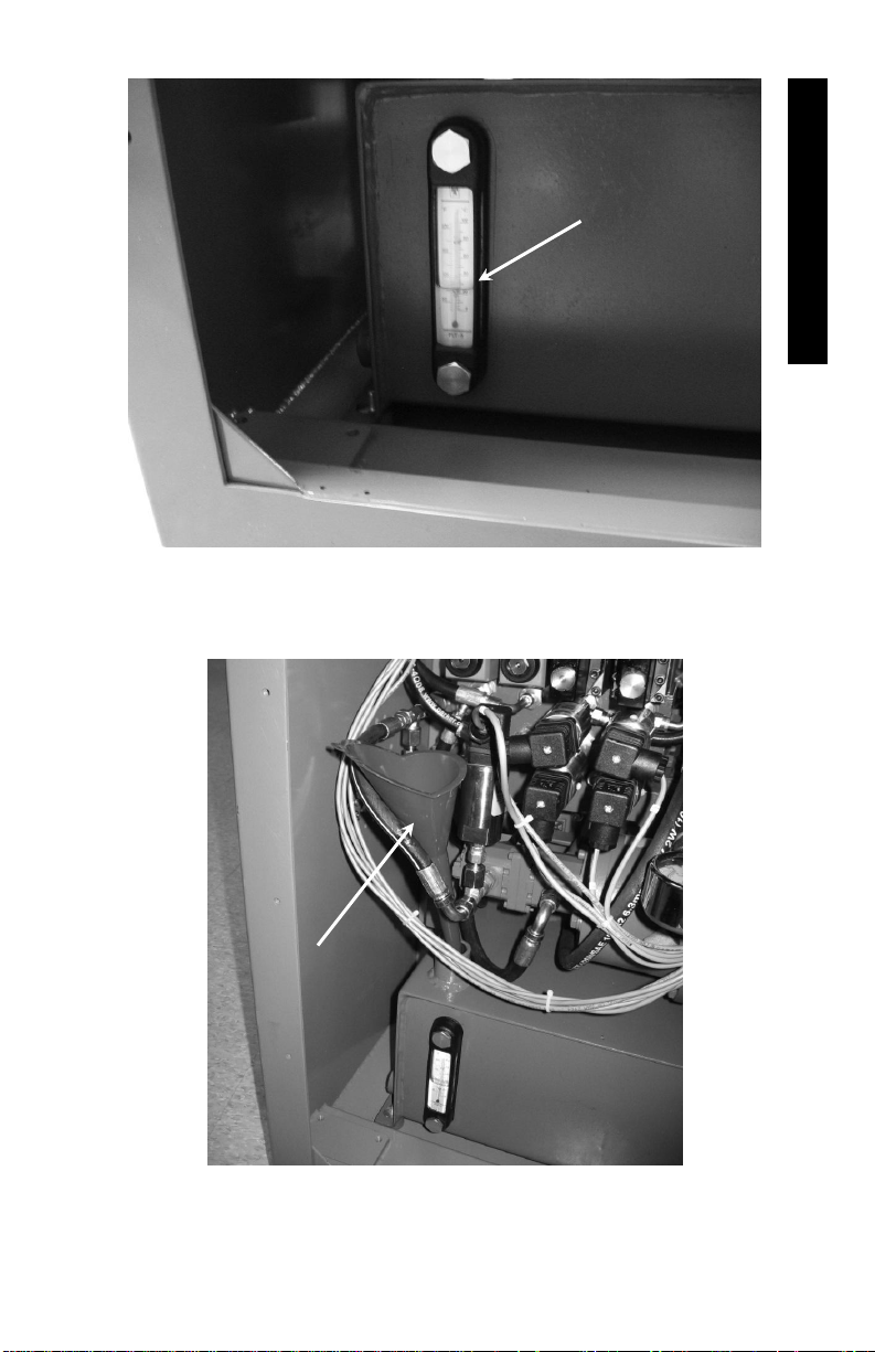
Remove the reservoir fill cap (see Figure 1–2) and place a
aa..
funnel into the fill tube as shown in Figure 1–4.
Add oil until the level is at the 30-degree mark.
bb..
Remove the funnel and replace the reservoir fill cap.
cc..
Re-install the rear service panel.
dd..
1–12
Figure 1–2. Hydraulic Reservoir
Page 23
1. INTRODUCTION
ENSURE
FLUID LEVEL
IS AT 30-DEGREE
MARK
FUNNEL
Figure 1–3. Proper Reservoir Fill Level
Figure 1–4. Place a Funnel in Reservoir Fill Tube
Model 5850 1–13
Page 24

Following the site selection guidelines in the previous section,
33..
set the compactor in place.
Lock the casters so that the unit remains in place.
44..
Plug the ac power cord into the ac power inlet on the
55..
compactor’s lower left panel (see Figure 1–1 on page 1–7).
Connect the ac power cord to the required ac power source
66..
(refer to Appendix C).
NOTE
On 240 VAC units, a connector must be installed on the
ac power cord. The connector must meet local safety and
electrical code requirements. Refer to the Electrical
Specifications section on page C–3 for the current and
voltage ratings for the compactor.
If using the compactor with a USB printer or memory device,
77..
connect the device to the USB port located on the upper left side
of the compactor (see Figure 1–1 on page 1–7).
NOTE
A list of USB memory devices and printers that are
compatible with the Model 5850 Gyratory Compactor is
available on the 5850 product page of the Troxler
website (www.troxlerlabs.com).
If using the compactor with a computer, use a serial cable to
88..
connect the computer to the serial port located on the upper left
side of the compactor (see Figure 1–1 on page 1–7).
1–14
Page 25

2. SETUP & OPERATION
CHAPTER 2
SETUP AND OPERATION
This chapter describes how to get started using the Model 5850
Gyratory Compactor. This information includes a brief description
of the control panel and instructions for turning the compactor on,
setting it up, and compacting an asphalt specimen.
CONTENTS
Control Panel ................................................................................ 2–2
Turning the System On ................................................................. 2–4
First Time Setup ..................................................................... 2–4
Compacting a Specimen ............................................................... 2–7
Cleaning and Lubricating.............................................................. 2–8
Preparing a Specimen ................................................................. 2–10
Compacting the Specimen .......................................................... 2–12
Model 5850 2–1
Page 26
KEY
FUNCTION
EMERGENCY
Stops all machine movement. To release
the button, rotate it clockwise.
START
Begins automatic compaction of asphalt
specimen.
SETUP
Accesses the Setup functions. These
include setting or viewing the run options,
setting the data output options, calibrating
the compactor, verifying the calibration,
and clearing project data.
ESC
Returns to the next higher-level menu
without updating or storing data. In
response to Yes/No questions, it has the
same effect as pressing NO/CE. During
gyration, it aborts the compaction cycle.
YES
Responds Yes to Yes/No questions.
NO/CE
Responds No to Yes/No questions. Also
clears an incorrect entry and allows for reentry.
Scrolls through menu options or views
screens.
0...9
Enters numeric values.
.
Enters a decimal point.
ENTER
Enters data or views screens.
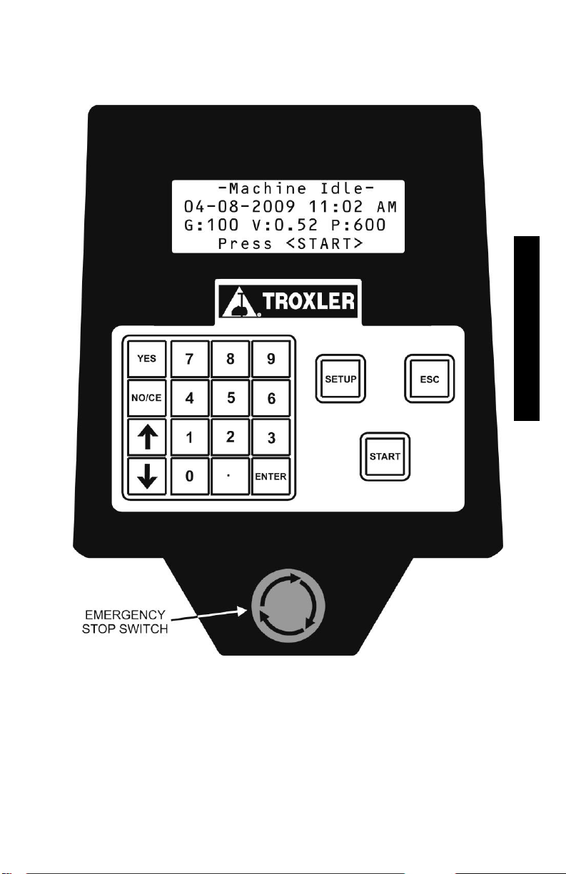
CONTROL PANEL
Figure 2–1 shows the layout of the Model 5850 Gyratory
Compactor control panel. Table 2–1 lists the functions for each key
and button on the panel.
Table 2–1. Control Panel Keys and Button
2–2
Page 27
2. SETUP & OPERATION
Figure 2–1. Model 5850 Control Panel Layout
Model 5850 2–3
Page 28
TURNING THE SYSTEM ON
NOTE
Control panel screens in this manual are intended as
examples only. Values on your displays may differ
slightly from those shown.
The power switch is located on the left side panel of the compactor
(see Figure 1–1). After the compactor is turned on, it briefly
displays the model and software version number, then performs a
series of brief self-tests. After self-tests are completed, the
compactor displays the Machine Idle screen shown below:
-Machine Idle04-08-2008 11:02 AM
G:100 AI:1.16 P:600
Press <START>
Where:
G = Operator-selected number of gyrations (this value is
999 if the compactor is set to compact to a target
specimen height)
AI = Operator-selected internal angle of gyration
P = Operator-selected compaction pressure
FIRST TIME SETUP
The Model 5850 is shipped with the current date and time (Eastern
Standard Time) stored in its memory. By default, the date is
displayed in mm/dd/yyyy format and the time in AM/PM format. To
change the date, time, or display format, refer to page 5–3.
The Model 5850 provides a number of operator-definable options
that control its operation. From the Setup menu, the operator can:
Select whether the compactor will run for a specified number of
gyrations (from 1 to 999) or until the specimen has been
compacted to a specified height (50 to 200 mm). Then define
the desired ram pressure (200 to 1000 kPa)
Set the desired gyration angle (0.00 to 1.50 degrees)
2–4
Page 29

2. SETUP & OPERATION
Before using the compactor for the first time, ensure that these
options are set properly. Press SETUP on the keypad to access
the Setup menu:
-Setup-
1- View Settings
2- Change Settings
3- Data Output
Press 1 to access the View Settings selection. The compactor
displays:
Selected run count (number of gyrations)
Selected mode (number of gyrations or specimen height)
Specimen height
Gyration angle
Ram pressure
Mold diameter
Gyrate Delay
Refer to Chapter 3 for instructions on changing any of these
selections.
The Model 5850 also provides numerous options for automatically
outputting or printing data following a compaction cycle. The
compactor can send the data to a computer or serial printer via the
serial (RS-232) port, or to a USB printer or memory device (thumb
drive) via the USB port.
NOTE
A list of compatible USB memory devices and printers is
available on the 5850 product page on Troxler’s website
at www.troxlerlabs.com.
Model 5850 2–5
Page 30

The output data can be formatted either in a height-versus-gyration
table format or in a full table format which includes the height, ram
pressure, gyration angle, and gyration rate for each gyration.
To automatically output gyration versus height data, connect the
compactor to the computer or printer and turn on the Auto Output
option as described on page 3–10.
NOTE
Before outputting data to a printer or computer, ensure
that the Model 5850 is properly connected to the output
device.
2–6
Page 31

2. SETUP & OPERATION
COMPACTING A SPECIMEN
WARNING
To prevent personal injury or equipment damage,
before operating the Model 5850 Gyratory
Compactor, become familiar with the safety
warnings on page 1–2.
The following is a checklist for compacting an asphalt specimen
with the Model 5850 Gyratory Compactor. Each step is discussed in
detail in the following sections.
Set up the gyratory compactor.
11..
Clean the mold tray, ram head, lower carriage, upper carriage
22..
assembly, and upper puck plate.
Lubricate the ram head and upper puck plate with Magnalube-
33..
G.
Prepare the asphalt mixture and place it in the mold.
44..
Place the mold in the compactor chamber, and compact the
55..
specimen.
Remove the mold containing the compacted specimen from the
66..
compactor chamber and extrude the asphalt specimen using the
gravity extruder provided with the compactor. A pneumatic
extruder is also available from Troxler (part number 116089).
Model 5850 2–7
Page 32

CLEANING AND LUBRICATING
CAUTION
Failure to properly clean and lubricate the Model 5850
before each use may result in compaction errors,
premature equipment wear, and other problems.
Before operating the compactor:
Vacuum the mold tray and compaction chamber.
11..
Clean the mold tray, lower carriage plate, and ram head (see
22..
Figure 2–2, View A), as well as the upper carriage assembly and
upper puck plate (View B) with Bindoff or similar cleaner.
Lubricate the ram head and the upper puck plate with
33..
Magnalube-G.
Clean the mold and pucks with Bindoff or similar cleaner.
44..
CAUTION
Do not use a degreasing cleaner or glass cleaner to clean
the clear chamber door. To prevent damage to the door
surface, use a mild detergent only.
Before each use:
If necessary, clean the mold tray, lower carriage plate, and ram
11..
head (see Figure 2–2, View A), as well as the upper carriage
assembly and upper puck plate (View B) with Bindoff or similar
cleaner.
Ensure that the exterior surface of the mold is free of dirt and
22..
asphalt residue.
Lubricate the ram head with Magnalube-G.
33..
Inspect the upper puck plate. If dry, lubricate it with Magnalube.
44..
2–8
Page 33

2. SETUP & OPERATION
LOWER
CARRIAGE
PLATE
RAM HEAD
MOLD TRAY
UPPER PUCK
PLATE
UPPER
CARRIAGE
ASSEMBLY
VIEW A
VIEW B
Figure 2–2. Compaction Chamber
Model 5850 2–9
Page 34

PREPARING A SPECIMEN
Lay the mold on its side and slowly insert the lower puck, with the
small face down, into the mold. For the rest of this chapter, the
mold with the puck inserted will be referred to as the mold.
WARNING
Always wear heat-resistant gloves when handling
any hot substance. When moving the mold, firmly
grasp it on either side under the top flange.
Place the asphalt mixture into an oven. Also place the mold
(containing the lower puck) into the oven. Heat the asphalt mixture
and mold to the compaction temperature of the mixture.
CAUTION
Do not heat the mold above 175 C (350 F). Heating
above this temperature may warp the mold and create
errors in the angle of gyration.
NOTE
Do not place the asphalt mixture into the mold while
heating.
Remove the asphalt mixture from the oven, and place it on a work
surface. Remove the heated mold from the oven and place it next to
the hot-mix asphalt.
Place a specimen paper in the heated mold on top of the lower puck
(see Figure 2–3). Load the hot asphalt mixture into the mold.
NOTE
To maintain the specimen temperature and prevent
segregation of the specimen, the asphalt mixture must
be loaded into the mold in one continuous motion. The
paper thickness will affect compactor results; it is
recommended that you use Troxler specimen papers
(part numbers 106952 or 106953).
2–10
Page 35

2. SETUP & OPERATION
MOLD (WITH
LOWER PUCK
INSTALLED)
ASPHALT
SPECIMEN
PAPERS
MOLD
PULL
UPPER PUCK
Figure 2–3. Loading the Mold
Place another specimen paper on top of the asphalt mix. Place the
upper puck, with its large side down, into the mold. Keep the upper
puck oriented horizontally while inserting it to prevent it from
becoming wedged in the mold.
CAUTION
If the upper or lower puck becomes wedged in the mold,
it must be removed and inserted correctly before
compacting the asphalt specimen.
Wearing heat-resistant gloves and safety glasses, place the hot
mold on the mold tray (see Figure 2–2, View A, on page 2–9).
Slide the mold into the compaction chamber so that it rests against
the two locating pins at the back of the lower carriage plate. Close
the chamber door.
Model 5850 2–11
Page 36

Gyration # =
Number of gyrations completed
Spec. Ht. =
The current specimen height
G =
Operator-selected number of gyrations (this value
is 999 if the compactor is set to compact to a
target specimen height)
AI =
Internal angle of gyration
P =
Operator-selected compaction pressure
COMPACTING THE SPECIMEN
The Model 5850 Gyratory Compactor provides a fully automatic
method of controlling compaction. In Automatic mode, the operator
begins the compaction cycle using a single keystroke. The Model
5850 compacts the specimen based on the number of gyrations or
the target specimen height specified by the operator. In Automatic
mode, the compactor can also automatically print or download
compaction data upon completion of the compaction cycle.
Place the loaded mold into the compaction chamber and close the
chamber door. Press START.
If there is no mold in the chamber, or if the mold is not in the proper
location, the compactor displays an error message.
If the mold is in place, the compactor begins the compaction cycle.
The compactor clamps the mold, raises the ram into position,
induces the angle of gyration, and begins compaction. During the
compaction cycle, the compactor displays a screen similar to the
one shown below:
-Gyrating-
Gyration: #:##
Spec. Ht.: ###.# mm
G:100 AI:1.16 P:600
Where:
2–12
Page 37

2. SETUP & OPERATION
The compactor continues until the desired number of gyrations or
target specimen height, as selected by the operator, is reached. The
compactor then unclamps the mold, removes the angle of gyration,
and lowers the ram to its home position.
If the Post Gyrate Delay function is enabled (see page 3–8), the
compactor will center itself and maintain a minimal pressure for five
minutes before unclamping the mold and lowering the ram.
If the Auto Output function (see page 3–10) is enabled, the
compactor automatically outputs the gyration versus height data.
The compactor then returns to the Machine Idle display shown on
page 2–4.
Open the chamber door and, wearing heat-resistant gloves,
remove the mold from the compaction chamber. Extrude the
specimen from the mold using the extruder provided with the unit.
You can also use the pneumatic extruder, available from your
Troxler representative.
SHEAR OPTIONS & PERFORMANCE TESTS
The Model 5850 can compact samples as tall as 185mm for use with
AMPT (Asphalt Mix Performance Tester). The compactor also
offers a shear option, either before or after purchase. This optional
feature includes transducers that measure the shear forces acting on
the specimen during gyration.
The Model 5850 also utilizes the Gyratory Shear Kit (GSK), which
turns any gyratory compactor into a shear-enabled unit without the
expense of purchasing the shear option. Place the 1.125” tall device
in your 150mm mold, fill with mix, and run the specimen. The GSK
calculates the shear moment at each rotation.
For more information about the shear option, or to learn more about
the Gyratory Shear Kit, contact Troxler at 1-877-TROXLER or visit
our website at www.troxlerlabs.com.
Model 5850 2–13
Page 38

NOTES
2–14
Page 39

3. SETUP MENU
CHAPTER 3
SETUP MENU
The compactor’s Setup menu enables the operator to select and
define the operating parameters of the Model 5850 Gyratory
Compactor. This chapter describes the many menu options.
CONTENTS
Setup Menu ................................................................................... 3–2
View Settings ................................................................................ 3–3
Change Settings ............................................................................ 3–4
Operation Mode...................................................................... 3–5
Number of Gyrations .............................................................. 3–5
Specimen Height .................................................................... 3–6
Gyration Angle ....................................................................... 3–6
Pressure .................................................................................. 3–7
Mold Diameter ....................................................................... 3–7
Post Gyrate Delay................................................................... 3–8
Data Output ................................................................................... 3–9
Output Record ...................................................................... 3–10
Auto Output .......................................................................... 3–10
Output Device ...................................................................... 3–11
Output Format ...................................................................... 3–11
Home Position ............................................................................ 3–13
Calibration .................................................................................. 3–13
Special......................................................................................... 3–13
Model 5850 3–1
Page 40

SETUP MENU
The compactor’s Setup menu enables the operator to select and
define the operating parameters of an automatic compaction cycle,
to determine the destination and format for outputting or
downloading compaction data, to calibrate the compactor, and to
perform other special functions.
To access the Setup menu, press SETUP on the keypad. Use the
arrow keys to scroll through the menu options. To select an option,
press the numeric key that corresponds to desired option. The
following sections describe each selection.
-Setup-
1- View Settings
2- Change Settings
3- Data Output
-Setup-
4- Home Position
5- Calibration
6- Special
3–2
Page 41

3. SETUP MENU
VIEW SETTINGS
To view the currently selected run options, select View Settings
from the Setup menu shown on page 3–2. The compactor displays:
Selected run count (number of gyrations)
Selected mode (number of gyrations or specimen height)
Specimen height
Gyration angle
Ram pressure
Mold diameter
Gyrate Delay
Press ESC to return to the Setup menu.
Model 5850 3–3
Page 42

CHANGE SETTINGS
The Change Settings selection from the Setup menu allows
you to:
Select whether the compactor will run for a specified number of
gyrations or until the specimen has been compacted to a
specified height
Specify the number of gyrations (from 1 to 999) the compactor
will run when compacting a specimen
Set the desired specimen height
Set the desired gyration angle (0.00 to 1.50 degrees)
Define the desired ram pressure (200 to 1000 kPa)
Select the mold diameter (150-mm, 100-mm, or 4-inch)
To access these options, press 2 from the Setup menu (see page
3–2). The Change Settings menu displays, as shown below. Use
the arrow keys to scroll through the menu options. To select an
option, press the numeric key that corresponds to desired option.
The following sections describe each selection.
3–4
-Change Settings-
1- Operation Mode
2- # of Gyrations
3- Height
-Change Settings-
4- Angle
5- Pressure
6- Mold Diameter
-Change Settings-
7- Post Gyrate Delay
Page 43

3. SETUP MENU
OPERATION MODE
The Model 5850 provides two modes of gyration. Based on operator
selection, the unit may either compact the specimen for a set number
of gyrations or until the specimen reaches a specified target height.
The default mode of gyration is the number of gyrations.
To select the gyration mode, press 1 from the Change Settings
menu shown on page 3–4. The compactor displays the Operation
Mode menu shown below.
-Operation Mode1- # Gyrations
2- Specimen Height
Press # to Select
Press the numeric key that corresponds to the desired operation
mode. The compactor displays a brief confirmation message, and
then returns to the Change Settings menu.
NUMBER OF GYRATIONS
To enter the number of gyrations for a compaction cycle, press 2
from the Change Settings menu shown on page 3–4. The
compactor displays:
Input Number of
Gyrations
100
Press <ENTER>
Use the number keys to enter the desired number of gyrations (from
1 to 999). Use the NO/CE key to backspace. Press ENTER. The
display returns to the Change Settings menu.
Model 5850 3–5
Page 44

SPECIMEN HEIGHT
The Model 5850 can also compact the asphalt specimen to a
specified target height. The operator can specify a height of 50 to
200 mm. The final specimen height may vary slightly from the
value entered. Differences in specimen height are mix dependent. If
the height is not acceptable, modify the height set on the unit.
To set the desired specimen height, press 3 from the Change
Settings menu shown on page 3–4. The compactor displays:
Input Target
Specimen Height (mm)
115.0
Press <ENTER>
Use the number keys to enter the specimen height (50 to 200 mm).
Use the NO/CE key to backspace. Press ENTER. The display
returns to the Change Settings menu.
GYRATION ANGLE
The Model 5850 can be set to an internal gyration angle of 0.00 to
1.50 degrees. To set the angle, press 4 from the Change
Settings menu shown on page 3–4. The compactor displays:
Input Gyration
Internal Angle
1.16
Press <ENTER>
Use the number keys to enter the desired gyration angle (from 0.00
to 1.50 degrees). Use the NO/CE key to backspace. Press
ENTER. The display returns to the Change Settings menu
shown on page 3–4.
3–6
Page 45

3. SETUP MENU
PRESSURE
NOTE
To ensure proper compactor operation, calibrate the
angle as described in Chapter 4 after changing the ram
pressure.
The Model 5850 ram pressure can be set between 200 and
1000 kPa. To set the ram pressure, press 5 from the Change
Settings menu shown on page 3–4. The compactor displays:
Input Compaction
Pressure (kPa)
600
Press <ENTER>
Use the number keys to enter the desired ram pressure (from 200 to
1000 kPa). Use the NO/CE key to backspace. Press ENTER.
The display returns to the Change Settings menu.
MOLD DIAMETER
CAUTION
Ensure that the mold diameter selected in the compactor
software is correct for the mold size in use before
compacting a specimen. Failure to select the proper
mold diameter in the software can cause erroneous
compaction results or equipment damage.
NOTE
To ensure proper compactor operation, calibrate the
compaction pressure and specimen height as described
in Chapter 4 after changing the mold diameter.
The Model 5850 can produce 150-mm, 100-mm, or 4-inch asphalt
specimens.
Model 5850 3–7
Page 46

To configure the compactor software for the diameter of the mold in
use, press 6 from the Change Settings menu on page 3–4. The
compactor displays:
-Mold Diameter1- 150mm
2- 100mm
3- 4in
Press the numeric key that corresponds to the desired mold
diameter. The compactor displays a brief confirmation message, and
then returns to the Mold Diameter menu shown above. Press ESC
to return to the Change Settings menu shown on page 3–4.
POST GYRATE DELAY
The Model 5850 provides the option for a five-minute delay upon
completing the compaction of a specimen. This delay maintains a
minimum pressure on the sample and allows low gyration
specimens to cool before the ram lowers.
To enable the Post Gyration Delay, press 7 from the Change
Settings menu. The compactor displays:
-Post Gyrate Delay1- Enable
2- Disable
Press 1 to enable the function and press 2 to disable it. The
compactor briefly displays the message Post Gyration Delay
is Enabled (or Disabled), and then returns to Change
Settings menu.
3–8
Page 47

3. SETUP MENU
DATA OUTPUT
The Model 5850 provides numerous options for outputting or
printing data. Compaction data can be printed manually from the
compactor’s memory or automatically upon completion of a
compaction cycle.
The compactor can send the data to a computer or serial printer via
the serial (RS-232) port, or to a USB printer or memory device
(thumb drive) via the USB port.
NOTE
A list of USB memory devices and printers that are
compatible with the Model 5850 Gyratory Compactor is
available on the 5850 product page on the Troxler
website (www.troxlerlabs.com).
The output data can be presented in either a height-versus-gyration
or full table format. These options are described on page 3–11.
NOTE
Before outputting data to a printer or computer, ensure
that the Model 5850 is properly connected to the output
device.
To configure the data output options, press 3 from the Setup
menu (see page 3–2). The compactor displays the Data Output
menu shown below. Use the arrow keys to scroll through the menu
options. To select an option, press the numeric key that corresponds
to desired option. The following sections describe each selection.
-Data Output-
1- Output Record
2- Auto Output
3- Output Device
-Data Output-
4- Output Format
Model 5850 3–9
Page 48

OUTPUT RECORD
The Output Record function allows the operator to manually
download or print compaction data stored in the compactor’s
memory. The compactor stores up to 20 data records that contain
information on the last 20 compaction cycles. Each data record
includes the sample height (in mm), ram pressure, gyration angle,
and gyration rate versus the gyration number for a specimen, as well
as the date and time of compaction. Printed table format data sets
also include a blank for the Sample ID.
To manually download or print a data record, press 3 from the
Data Output menu shown on page 3–9. The compactor searches
the data records and then displays the specimens currently stored in
memory, as shown below:
>04/08/09 04:24P
04/08/09 01:52P
04/08/09 08:45A
04/08/09 08:15A
Using the arrow keys, move the cursor () to the desired data record
and press ENTER. The compactor sends the specimen data in the
desired format to the selected device (see page 3–11), then returns to
the Data Output menu.
AUTO OUTPUT
Upon completion of a compaction cycle, the Model 5850 can
automatically download or print gyration data via the serial or USB
port.
To toggle the Auto Output feature on or off, press 2 from the Data
Output menu shown on page 3–9. The compactor briefly displays
the message Auto Output Is Now ON (or OFF), then returns to
the Data Output menu.
3–10
Page 49

3. SETUP MENU
OUTPUT DEVICE
The compactor can send the data to a computer or serial printer via
the serial (RS-232) port, or to a USB printer or memory device
(thumb drive) via the USB port. To select the destination for the
output data, press 3 from the Data Output menu shown on page
3–9. The compactor displays:
-Output Destination1- Serial Port
2- USB Printer
3- Thumb Drive
Press the numeric key that corresponds to the desired output
destination. The compactor displays a brief confirmation message
and returns to the Output Destination menu. Press ESC to
return to the Data Output menu.
The GyroImport software is used to convert the data on the USB
memory device to a Microsoft Excel workbook. The software may
be downloaded from the 5850 product page on the Troxler website
(www.troxlerlabs.com) or it can be requested from Customer
Service at 1-877-TROXLER.
OUTPUT FORMAT
The Model 5850 outputs data in a height-versus-gyration format,
similar to the one shown in Figure 3–1, and shows the specimen
height, or thickness, for each gyration during a compaction cycle. A
full table output includes specimen height, gyration angle, ram
pressure, and shear stress (if enabled) for each gyration.
To print the output data, press 4 from the Data Output menu
(shown on page 3–9). The compactor displays:
Model 5850 3–11
-Output Format1- Table
2- Formatted
3- GyroPave
Page 50

Press 1 to select the Table format. The compactor displays a
brief confirmation message, and then returns to the Data
Output menu.
Figure 3–1. Sample Height Versus Gyration Table
Press 2 to select the formatted data. The data is output in
Comma Separated Variable (.csv) format. The compactor
displays a confirmation message, and then returns to the
Data Output menu.
Press 3 to select GyroPave software compatible data format.
The data is similar to the Table format, but only height
measurements are output. The compactor displays a
confirmation message and then returns to the Data Output
menu.
NOTE
If Thumb Drive is the selected output device, the result
will be the following files: Ax.hdr (header file); Ax.txt
(formatted data format); AxGP.txt (GyroPave data
format); AxTABLE.txt (table data format). (Where “x”
represents the file index number of the data stored in
the compactor’s memory.)
3–12
Page 51

3. SETUP MENU
HOME POSITION
The Model 5850 contains hydraulic actuators that control specimen
compaction. One actuator applies ram pressure; another actuator
clamps the mold; and two actuators inside the compaction chamber
set and control the gyration angle.
The Home Position function returns all the hydraulic actuators to
their home position. To access this function, press 4 from the
Setup menu (see page 3–2). The compactor drives the four
actuators to their home position, while displaying Moving
Gyratory to Home Position. When the actuators are in their
home position, the compactor returns to the Setup menu.
CALIBRATION
Chapter 4 describes the calibration functions available from the
compactor’s Calibration menu. To access this menu, press 5
from the Setup menu (see page 3–2).
SPECIAL
Chapter 5 describes the functions available from the compactor’s
Special menu. To access this menu, press 6 from the Setup
menu (see page 3–2).
Model 5850 3–13
Page 52

NOTES
3–14
Page 53

4. CALIBRATION
CHAPTER 4
CALIBRATION
The Model 5850 allows for simple calibration of the specimen
height and compaction pressure, and for offsetting the angle of
gyration. This chapter provides a recommended schedule for
calibration and verification of these parameters, as well as
instructions for performing these procedures.
CONTENTS
Calibration Schedule ..................................................................... 4–2
Pressure Calibration ............................................................... 4–2
Specimen Height Calibration ................................................. 4–2
Angle Verification and Offset ................................................ 4–2
Angle Verification ........................................................................ 4–3
Calibration .................................................................................... 4–5
Pressure .................................................................................. 4–6
Specimen Height .................................................................. 4–10
Angle Offset ......................................................................... 4–12
Print Calibration ................................................................... 4–13
Model 5850 4–1
Page 54

CALIBRATION SCHEDULE
The Troxler Model 5850 Gyratory Compactor is calibrated at the
factory, and requires no initial calibration upon receipt.
Troxler recommends the following calibration schedule for the
Model 5850. If calibrating the compaction pressure and specimen
height, calibrate the pressure first and then calibrate the height.
NOTE
To ensure proper compactor operation, calibrate the
compaction pressure and specimen height after
changing the ram pressure (see page 3–7).
PRESSURE CALIBRATION
See page 4–6 for details on pressure calibration.
Calibrate the compaction pressure every 3 months.
SPECIMEN HEIGHT CALIBRATION
See page 4–10 for details on specimen height calibration.
Calibrate the specimen height daily.
Calibrate the specimen height after calibrating the compaction
pressure.
ANGLE VERIFICATION AND OFFSET
See page 4–3 for details on angle verification.
Verify the angle as described on page 4–3 after every 800 samples
or once per year, whichever comes first. If the angle is more than
±0.03° from the target, use the Angle Offset function as described on
page 4–12.
4–2
Page 55

4. CALIBRATION
ANGLE VERIFICATION
The operator-selected internal angle of gyration is displayed on the
Machine Idle screen as well as during gyration. This angle can be
easily verified using an internal angle device, such as the Dynamic
Angle Verification (DAV) device available from Troxler (part
number 108706).
To verify the internal angle, follow the instructions in Chapter 3 to:
Set the operation mode to number of gyrations.
11..
Set the number of gyrations to 20.
22..
Set the compaction pressure to 600 kPa.
33..
Set the gyration angle to 1.16.
44..
NOTE
To ensure the accuracy of internal angle measurements,
the probes of the internal angle device must be aligned
with the edge of the mold pull as shown below.
Figure 4–1. Aligning the Internal Angle Device Probes
Model 5850 4–3
Page 56

Follow the instructions provided with the internal angle device
55..
to measure the bottom angle. Ensure that the probes of the
internal angle device are aligned along Position 1 with the edge
of the mold pull as shown in Figure 4–1.
Remove the mold from the chamber and record the measured
66..
angle from the internal angle device (if you use a device with
recording capabilities).
Repeat the two previous steps to obtain a second bottom angle
77..
measurement where the device is aligned along Position 2.
Follow the instructions provided with the internal angle device
88..
to measure the top angle. Ensure that the probes of the internal
angle device are aligned along Position 1 with the edge of the
mold pull as shown in Figure 4–1.
Remove the mold from the chamber and record the measured
99..
angle from the internal angle device.
Repeat the two previous steps to obtain a second top angle
1100..
measurement where the device is aligned along Position 2.
Calculate the average of the bottom angle and top angle
1111..
measurements (four measurements total).
Compare the average to the entered angle of 1.16. If the
1122..
difference is more than ±0.03°, refer to the Angle Offset section
on page 4–12.
4–4
Page 57

4. CALIBRATION
CALIBRATION
WARNING
To prevent personal injury or equipment damage,
before operating the Model 5850 Gyratory
Compactor, become familiar with the safety
warnings on page 1–2.
The Model 5850 allows for simple calibration of the compaction
pressure and specimen height, and for offsetting the gyration angle.
To access the Calibration menu, press 5 from the Setup menu
shown on page 3–2. The compactor displays:
-Calibration-
1- Pressure
2- Height
3- Angle Offset
-Calibration-
4- Print Calibration
Use the arrow keys to scroll through the menu options. To select an
option, press the numeric key that corresponds to desired option.
The following sections describe each selection.
Model 5850 4–5
Page 58

PRESSURE
NOTE
For optimum performance—if operating the compactor
at a ram pressure other than 600 kPa—calibrate the
specimen height and gyration angle after changing the
ram pressure (see page 3–7).
The Pressure Verification Kit includes all the equipment needed to
calibrate and/or verify the compaction pressure, including a
calibration load cell.
Before calibrating or verifying the pressure, clean the compactor
and connect the load cell as described below:
To remove any grease or asphalt, clean the mold tray, ram head,
11..
lower carriage plate, upper carriage assembly, and upper puck
plate (see Figure 2–2 on page 2–9) with Bindoff or similar
cleaner.
Connect the load cell as follows:
22..
Using the supplied serial cable, connect the load cell to the
aa..
control unit’s serial port.
Connect the dc charger to the load cell, and plug the charger
bb..
into an electrical outlet.
To begin pressure calibration, press 1 at the Calibration menu
shown on page 4–5. The compactor displays:
Connect Load cell to
ser. Port. Set it in
chamber (ON A PUCK!)
Press <ENTER>
CAUTION
Ensure that the load cell is placed on a puck as
described below. Failure to do so will cause damage to
the load cell.
4–6
Page 59

4. CALIBRATION
PUCK
LOWER
CARRIAGE PLATE
LOAD
CELL
Place the lower puck, larger edge down, in the center of the
11..
lower carriage plate as shown in Figure 4–2.
Place the calibration load cell in the center of the puck as shown
22..
below.
Place the upper puck, larger edge down, centered on top of the
33..
load cell.
Route the load cell cables through the notch in the upper center
44..
of the chamber opening as shown in Figure 4–3. Close the
chamber door.
Model 5850 4–7
Figure 4–2. Puck Centered on Lower Carriage Plate
Page 60

ROUTE CABLES
THROUGH
NOTCH
LOAD
CELL
Figure 4–3. Routing Load Cell Cables
4–8
Page 61

4. CALIBRATION
CAUTION
Use caution when opening and closing the chamber door
to prevent catching or pinching the load cell cables.
Press ENTER. The compactor measures the unloaded
55..
pressure on the load cell. During this measurement, the control
unit displays:
Pressure Cal/Verify
Testing Calibration
Load Cell
Please Wait
NOTE
If the load cell is not properly connected, the control
unit briefly displays the following error message. Check
the load cell connection. Press ENTER to continue.
Pressure Cal/Verify
Communication Error
Check Load Cell
Press <ENTER>
After measuring the unloaded pressure on the load cell, the
66..
compactor raises the ram until the load cell contacts the upper
puck plate. The compactor then applies pressure and displays:
Pressure Cal/Verify
Applying Pressure
During calibration and verification, the compactor raises the
compaction ram and performs a series of pressure measurements at
high and low pressure. Upon completion, the compactor verifies the
pressure calibration, and then displays the compaction pressure as
measured internally by the compactor (System) and as measured by
the load cell (Load Cell):
Model 5850 4–9
Page 62

-Pressure Readings System: ###
Load Cell: ###
Press <ENTER>
If the System pressure differs from the Load Cell pressure by
77..
more than 10 kPa, or if the System pressure is not within 600
18 kPa, check all cable connections and the position of the
load cell and puck. Repeat the calibration. If repeated attempts
to calibrate the pressure fail, contact your Troxler
representative.
Press ENTER. The compactor stores new calibration
88..
constants based on the System and Load Cell values. It then
lowers the ram and returns to the Calibration menu shown on
page 4–5.
Open the chamber door and remove the calibration load cell and
99..
pucks. Unplug the dc charger from the electrical outlet, and
disconnect the load cell from the dc charger and control unit.
Return all parts to the Performance Verification Kit case.
SPECIMEN HEIGHT
If calibrating the height and pressure, calibrate the pressure first.
Then calibrate the specimen height.
NOTE
For optimum performance—if operating the compactor
at a ram pressure other than 600 kPa—calibrate the
specimen height and gyration angle after changing the
ram pressure.
NOTE
Before calibrating the specimen height, clean the ram
head, lower carriage plate, upper carriage assembly,
and upper puck plate with de-greaser. Failure to do so
may cause the height calibration to be inaccurate.
4–10
Page 63

4. CALIBRATION
A height standard assembly is supplied with each compactor. This
standard, along with two pucks and two specimen papers, is used to
calibrate the specimen height.
To begin height calibration, press 2 at the Calibration menu
11..
shown on page 4–5. The compactor displays:
Put Height Std,
Pucks and Papers
Into the Chamber
Press <ENTER>
Place a clean puck, with the large side down, in the center of the
22..
carriage plate. Place two specimen papers and the height
standard assembly in the center of the puck. Place a second
clean puck on the top of the height standard assembly.
Close the chamber door and press ENTER. The compactor
33..
displays:
Height Calibration
Enter Std Height
###.##
Press <ENTER>
The height of the height standard assembly is stamped on its side.
Enter the height to the nearest hundredth and press ENTER. The
compactor finds its home position and then raises the ram until the
upper puck reaches the upper puck plate.
The compactor then applies pressure and waits for the pressure to
stabilize. When the pressure has stabilized, the compactor takes a
series of measurements and then verifies the height calibration.
When the calibration is complete, the compactor displays the
Measured height and the Standard height, as shown below. The
displayed height should be within 0.10 mm of the value stamped
on the height standard assembly. If not, repeat the height calibration.
Model 5850 4–11
Page 64

Height Calibration
Measured:###.##mm
Standard:###.##mm
Press <ENTER>
Press ENTER. The compactor stores the new calibration
44..
constants based on the Measured and Standard values. It then
displays the message Calibration Finished and lowers the
ram to its home position. When the ram reaches the home
position, the compactor returns to the Calibration menu shown
on page 4–5. Open the chamber door and remove the height
standard assembly, pucks, and specimen papers.
ANGLE OFFSET
The Model 5850 can be set to a gyration angle of 0.00 to 1.50
degrees. As noted earlier, Troxler recommends verifying the angle
after every 800 samples or once per year using an internal angle
device, such as the Dynamic Angle Verification (DAV) device
available from Troxler. Refer to page 4–3 for instructions on
verifying the angle.
Use the internal angle device during verification to take two bottom
angle measurements and two top angle measurements. Determine
the average of these four measurements. If the average angle is more
than ±0.03° from the target, the Angle Offset function can be used to
compensate for the difference by comparing control system
feedback parameters to the average measured internal angle.
To use the Angle Offset function, press 3 at the Calibration menu
shown on page 4–5. The compactor displays:
-Angle Offset-
0.00 Degrees
1- Change
2- Enable
4–12
Page 65

4. CALIBRATION
Press 1 to enter the average of the four internal angle
measurements. The compactor displays:
Input Measured
Internal Angle
#.###
Press <ENTER>
Enter the measured angle and press ENTER. The compactor
displays the following (where #.## is the value just entered):
-Angle Offset #.## Degrees
1- Change
2- Enable
To enable the Angle Offset function using this value, press 2.
PRINT CALIBRATION
The Print Calibration function can be used to manually download
or print calibration data from the compactor. To use this function,
press 4 at the Calibration menu shown on page 4–5. The
compactor sends the calibration data to the selected output device
(see page 3–11), then returns to the Calibration menu.
Model 5850 4–13
Page 66

NOTES
4–14
Page 67

5. SPECIAL FUNCTIONS
CHAPTER 5
SPECIAL FUNCTIONS
The Model 5850 Gyratory Compactor firmware includes a number
of functions that typically are not used on a day-to-day basis. These
functions are accessed from the Special menu, which is a submenu
of the Setup menu.
CONTENTS
Special Menu ................................................................................ 5–2
Clock/Calendar ............................................................................. 5–3
Change Time .......................................................................... 5–3
Change Date ........................................................................... 5–4
Time Format ........................................................................... 5–5
Date Format ............................................................................ 5–5
Erase Records ............................................................................... 5–6
Reset Software .............................................................................. 5–7
Model 5850 5–1
Page 68

SPECIAL MENU
The Special menu provides access to a number of functions that
typically are not used on a day-to-day basis. These functions enable
the operator to set the date and time, to clear all project (specimen)
data, and to reset the software.
To access these functions, press 6 from the Setup menu. The
compactor displays the Special menu shown below.
-Special-
1- Clock/Calendar
2- Erase Records
3- Reset Software
Use the arrow keys to scroll through the menu options. To select an
option, press the numeric key that corresponds to the desired option.
The following sections describe each selection.
5–2
Page 69

5. SPECIAL FUNCTIONS
CLOCK/CALENDAR
The compactor stores the gyration data for the last 20 specimens,
using the date and times to identify each specimen. The time and
date of compaction are downloaded with the data.
To set the current time and date, press 1 from the Special menu
shown on page 5–2. The compactor displays the Clock/Calendar
menu shown below. Use the arrow keys to scroll through the menu
options. To select an option, press the numeric key that corresponds
to desired option. The following sections describe each selection.
-Clock/Calendar-
1- Change Time
2- Change Date
3- Time Format
-Clock/Calendar-
4- Date Format
CHANGE TIME
To set the time, press 1 from the Clock/Calendar menu shown
above. The compactor displays:
08:45 AM
Arrows toggle AM/PM
Input Time and
Press <ENTER>
Note that in this example, the time is displayed in AM/PM format.
To change the format, see the Time Format section on page 5–5.
Model 5850 5–3
Page 70

The top line of the display shows the current clock setting. To
accept this setting, press ENTER. The compactor returns to the
Clock/Calendar menu. To change the clock setting, enter the
current time using the numeric keys and press ENTER. The
compactor returns to the Clock/Calendar menu.
NOTE
The hour and minutes must be entered as two-digit
numerals, with leading zeroes as required. For example,
to set the time to 7:06, press 0 7 0 6, and then
press ENTER.
CHANGE DATE
To set the date, press 2 from the Clock/Calendar menu shown
on page 5–3. The compactor displays:
04/08/2009
mm/dd/yyyy
Input Date and
Press <ENTER>
Note that in this example, the date is displayed in mm/dd/yyyy
format. To change the format, see the Date Format section on page
5–5.
The top line of the display shows the current date setting. To accept
this date and return to the Clock/Calendar menu, press ENTER.
To change the date, enter the current date using the numeric keys
and press ENTER. The compactor returns to the
Clock/Calendar menu.
NOTE
The month and day must be entered as two-digit
numerals, with leading zeroes as required. The year
must be entered as a four-digit numeral. For example, to
set the date to April 8, 2009, press 0 4 0 8 2 0
0 9, then press ENTER.
5–4
Page 71

5. SPECIAL FUNCTIONS
TIME FORMAT
The compactor can display the time in either AM/PM or 24-hour
format. To set the desired format, press 3 from the
Clock/Calendar menu shown on page 5–3. The compactor
displays:
-Time Format1- AM/PM
2- 24-Hour
Press the numeric key that corresponds to the desired time format.
The compactor returns to the Clock/Calendar menu.
DATE FORMAT
The compactor can display the date in either mm/dd/yyyy or
dd/mm/yyyy format, where mm = month, dd = day, and yyyy = year.
To set the desired format, press 4 from the Clock/Calendar
menu shown on page 5–3. The compactor displays:
-Date Format1- mm/dd/yyyy
2- dd/mm/yyyy
Press the numeric key that corresponds to the desired date format.
The compactor returns to the Clock/Calendar menu.
Model 5850 5–5
Page 72

ERASE RECORDS
The Erase Records function erases all data records stored in the
compactor’s memory. To erase data records, press 2 from the
Special menu shown on page 5–2. The compactor displays:
Permanently Erase
all Data Records?
<YES> or <NO>
To erase all data records, press YES. The compactor restores
the default settings, displays a brief confirmation message, and
returns to the Special menu.
To return to the Special menu without erasing the data records,
press NO/CE or ESC.
5–6
Page 73

5. SPECIAL FUNCTIONS
RESET SOFTWARE
The Reset Software function restores all software functions and
settings to their default (factory) settings.
NOTE
The Reset Software function does not erase data records
or calibration constants stored in the compactor
memory.
To use this function, press 3 from the Special menu shown on
page 5–2. The compactor displays:
System Reset Sets
System Variables to
Defaults! Continue?
<YES> or <NO>
To restore the default settings, press YES. The compactor
restores the default settings, displays a brief confirmation
message, and returns to the Special menu.
To return to the Special menu without restoring the default
settings, press NO/CE or ESC.
Model 5850 5–7
Page 74

NOTES
5–8
Page 75

A. TROUBLESHOOTING
APPENDIX A
TROUBLESHOOTING AND SERVICE
This appendix contains information on servicing and maintaining
the Model 5850 Gyratory Compactor.
CONTENTS
Troubleshooting ........................................................................... A–2
General Maintenance Schedule ................................................... A–4
Daily, Before Use .................................................................. A–4
Before Each Cycle ................................................................. A–4
Every 80 Hours of Operation ................................................ A–5
Every 500 Hours of Operation or Once a Year ..................... A–6
Replacing the Batteries ................................................................ A–7
Replacement Parts ....................................................................... A–8
Optional Accessories ............................................................. A–8
Returning Parts for Service .......................................................... A–9
Model 5850 Appendix A–1
Page 76

TROUBLESHOOTING
WARNING
To prevent personal injury or equipment damage,
become familiar with the safety warnings on page
1–2 before operating the compactor.
Gyratory compactor does not turn on
Ensure that the unit is plugged in.
11..
Check that the power switch is in the ON position.
22..
Ensure the Emergency Stop button is not engaged.
33..
Check the power to the wall outlet.
44..
Check that the fuse for the wall outlet is not blown or that the
55..
circuit breaker is not tripped.
Moving parts are not moving
Ensure the unit is turned on.
11..
Check that the chamber door is closed.
22..
A switch may be broken. Check the service panels and
33..
emergency switches.
Verify that the hydraulic oil in the reservoir is at the proper
44..
level, as described on page 1–12. Fill, if necessary, with light
grade (ISO VG 32, SAE 10) hydraulic oil.
Gyration data does not download to the computer
Check that the computer is properly connected to the
11..
compactor’s serial port.
Check that the Auto Output feature is enabled (see page 3–10).
22..
Check that the serial port is specified as the output device (see
33..
page 3–11).
Appendix A–2
Page 77

A. TROUBLESHOOTING
Gyration data does not print automatically following a
compaction cycle
Ensure that the Auto Output feature is enabled (see page 3–10).
11..
Ensure that the proper output device is selected (see page 3–11).
22..
Gyration data does not print or download properly
Ensure that the Auto Output feature is enabled (see page 3–10).
11..
If printing or downloading data to a USB device, ensure that the
22..
device is compatible with the compactor. A list of compatible
USB memory devices and printers is available on the 5850
product page at www.troxlerlabs.com/.
General calibration problems
Check all cable connections.
11..
For the height calibration, ensure that the puck, specimen
22..
papers, and height standard assembly are located properly on
the lower carriage plate.
For the pressure calibration, ensure that the pucks and the load
33..
cell are located properly on the lower carriage plate.
Repeat the calibration once. If you still have problems with the
44..
calibration, call your Troxler representative.
Compactor displays: Pressure Calibration
Communication Error
Check all connections between the compactor and the external
11..
load cell.
Check the power connection to the load cell.
22..
All other compactor error messages
Record the error message, and then contact Troxler at
1.877.TROXLER (1.877.876.9537) for further information.
Model 5850 Appendix A–3
Page 78

GENERAL MAINTENANCE SCHEDULE
The following sections provide a recommended schedule for
performing regular maintenance on the Model 5850 Gyratory
Compactor.
CAUTION
Do not use a degreasing cleaner or glass cleaner to clean
the clear chamber door. To prevent damage to the door
surface, use a mild detergent only.
NOTE
Use any degreasing cleaner and a clean rag to clean
metal parts. See the safety warnings on page 1–2.
DAILY, BEFORE USE
Vacuum the mold tray and compaction chamber.
11..
Clean the mold tray, lower carriage plate (including the mold
22..
positioning pins), and ram head (see Figure 2–2, View A, on
page 2–9), as well as the upper carriage assembly and upper
puck plate (View B) with Bindoff or similar cleaner.
Clean the mold and pucks with Bindoff or similar cleaner.
33..
BEFORE EACH CYCLE
If necessary, clean the mold tray, lower carriage plate (including
11..
the mold positioning pins), and ram head (see Figure 2–2,
View A, on page 2–9), as well as the upper carriage assembly
and upper puck plate (View B) with Bindoff or similar cleaner.
Ensure that the exterior surface of the mold is free of dirt and
22..
asphalt residue.
Lubricate the ram head with Magnalube-G.
33..
Inspect the upper puck plate. If dry, lubricate it with
44..
Magnalube-G.
Appendix A–4
Page 79

A. TROUBLESHOOTING
EVERY 80 HOURS OF OPERATION
Wipe or scrape away any asphalt residue that has adhered to the
11..
mold tray, lower carriage plate, ram head, upper carriage
assembly, or upper puck plate (see Figure 2–2, View A, on page
2–9)
After cleaning, wipe the areas with a clean, dry cloth.
22..
Inspect the ram head. Check for pitting or chipping. If
33..
replacement is necessary, contact your Troxler representative.
Check the following for excessive wear (damage beyond the
44..
point of operation) or damage:
Lower carriage plate and upper carriage assembly – Ensure
that the surface is reasonably flat. Check for deep gouges,
pitting or chipping. If replacement is necessary, contact
your Troxler representative.
Ram head – Ensure that the surface is reasonably flat.
Check for deep gouges, pitting or chipping. If replacement
is necessary, contact your Troxler representative.
Mold positioning pins (in the lower carriage plate) – Check
for wear or flattening. Replace if necessary.
Pucks – Ensure that the surfaces are reasonably flat. Check
for pitting or chipping. Replace if necessary.
Mold – Check for pitting or chipping. Check upper and
lower flanges for wear (flat area wider than 0.2 inches).
Replace if necessary.
Retaining ring (inside the bottom of the mold) – Ensure that
the ring is in place. If necessary, return the mold to Troxler
for servicing.
Remove the rear service panel and perform the following steps:
55..
Hydraulic oil level – Locate the fill level sight glass as
shown in Figure 1–2 on page 1–12. Ensure that the oil level
is at the 30-degree mark on the sight glass, as shown in
Figure 1–3 on page 1–13. If oil is needed, remove the
reservoir fill cap (see Figure 1–2), place a funnel into the fill
tube as shown in Figure 1–4, and add a light grade (ISO VG
32, SAE 10) hydraulic oil as necessary. Remove the funnel
and replace the reservoir fill cap.
Model 5850 Appendix A–5
Page 80

ENSURE
BYPASS INDICATOR
IS GREEN
NOTE
Use only a light grade (ISO VG 32, SAE 10) hydraulic
oil to fill the hydraulic reservoir.
Hydraulic power unit – Examine all hoses and fittings for
leaks.
Hydraulic hoses and braided sleeve – Examine the hydraulic
hoses and their braided sleeves for wear. If the sleeve is
worn through and the rubber hydraulic hose is worn, replace
the hose and sleeve.
Open the chamber door and examine each hydraulic hose for
66..
wear. If the rubber cover is worn, replace the hose.
EVERY 500 HOURS OF OPERATION OR ONCE A
YEAR
Remove the right-side service panel. Locate the hydraulic filter
11..
(see Figure A–1). Verify that the bypass indicator on the top of
the filter housing is green. If the bypass indicator is red, the
filter element must be changed. Contact your Troxler
representative for more information.
Figure A–1. Hydraulic Filter Bypass Indicator
Appendix A–6
Page 81

A. TROUBLESHOOTING
REPLACING THE BATTERIES
The compactor uses two AA batteries to maintain the real-time
clock (date and time). To avoid loss of the real-time clock settings,
replace the batteries at least once a year.
WARNING
Carefully note the polarity of the batteries when
installing them in the battery holder. A battery may
explode or leak if installed improperly.
The battery holder is located behind the control panel. To replace
the batteries:
Turn the power switch off and disconnect the ac power cord
11..
from the left side connector (see Figure 1–1 on page 1–7).
Remove the four screws that secure the control panel.
22..
Carefully remove the control panel, using care not to damage
33..
any of the cables connected to it.
The battery holder is located on the rear of the control panel.
44..
Note the polarity of the AA batteries.
Remove the old batteries and install new AA batteries.
55..
NOTE
If the new batteries are installed within approximately
one minute after the old ones are removed, the real-time
clock settings should be maintained.
Install the control panel using the four screws removed in
66..
step 2.
Reconnect the ac power cord and turn the power switch on.
77..
Verify that the compactor displays the current date and time.
88..
Reset, if necessary, as described on page 5–3.
Model 5850 Appendix A–7
Page 82

REPLACEMENT PARTS
The list below shows part numbers for parts that are replaced often.
Other replacement parts can be ordered by calling 1-877-
TROXLER or visiting our online catalog at www.troxlerlabs.com.
PART # DESCRIPTION
106514 Cable, serial, 8-ft
110697 Cable, USB communications
110665 Gravity extruder
106989 Height standard assembly
116066 Mold assembly, 100 mm
116069 Mold assembly, 150 mm
116901 Model 5850 Manual of Operation and Instruction
108664 Power cord, 13 A, 10-ft
116220 Printer, 5850
106953 Specimen paper, 150 mm (1 package)
OPTIONAL ACCESSORIES
PART # DESCRIPTION
108706 Pressure Verification Kit
110062 Dynamic Angle Verification (DAV) II with HMS system
116089 Pneumatic Extruder
018141 Bindoff (1 gallon)
012786 Lubricant, Magnalube-G (1-lb can)
018290 Lubricant brush
018682 Heat-resistant gloves
Call GyroImport Software and Operator Manual
Call Shear Measurement Upgrade
Appendix A–8
Page 83

A. TROUBLESHOOTING
RETURNING PARTS FOR SERVICE
All shipments to the factory must be accompanied by a Returned
Goods Authorization (RGA) number, and a description of the
instrument, and its problem. This information is used by Troxler
shipping and service personnel to expedite the repair work.
To obtain an RGA number, please call or fax the factory or branch
office with your request. Please have the following information
available when contacting Troxler for an RGA number:
Unit (or part) model and serial number.
Part number/serial number (if applicable).
Is the unit (part) still under warranty?
Problem or difficulty you are having with the unit.
Shipment method to Troxler and for return shipment.
Shipping and billing address (not P.O. Box) – street address and
zip.
Telephone number/contact (for questions from Troxler).
Will an estimate be required prior to performing any work on
the part?
Payment method: credit card, account number, or purchase
order number. All government agencies (city, county, state,
and federal) are required to send purchase order numbers.
NOTE
To prevent order duplication, if an order has been
placed by telephone, please write “Confirming Order”
on any follow-up written requests.
Model 5850 Appendix A–9
Page 84

NOTES
Appendix A–10
Page 85

B. MENU MAP
APPENDIX B
MENU MAP
This appendix provides a map of the menus in the Model 5850
Gyratory Compactor control software.
CONTENTS
Menu Map Description ................................................................. B–2
Model 5850 Appendix B–1
Page 86

MENU MAP DESCRIPTION
Figure B–1 is a map of the compactor’s Setup menu and each of its
submenus. To access the Setup menu, press Setup. Where
applicable, the default (as shipped) menu settings are shown in
shaded text.
The menu map uses indentation to indicate submenus that result
from selection of a menu item. For example, the first eight lines of
Figure B–1 are:
-Setup1– View Settings
2- Change Settings
-Change Settings1- Operation Mode
-Operation Mode1- # Gyrations
2- Specimen Height
This indicates that the first two menu items under the –Setup-
menu are View Settings and Change Settings. When the
Change Settings item is selected, the compactor displays the
Change Settings submenu.
The first menu item under the Change Settings submenu is
Operation Mode. When this item is selected, the compactor
displays the Operation Mode submenu, which has two menu
items, # Gyrations and Specimen Height.
NOTE
The menu map contains only the displays that allow or
require a choice by the operator. Other displays (such as
numerical entries, status information, confirmation
messages, or error displays) are not included.
Appendix B–2
Page 87

B. MENU MAP
Figure B–1. Model 5850 Menu Map
-Setup1– View Settings
2- Change Settings
-Change Settings1- Operation Mode
-Operation Mode1- # Gyrations
2- Specimen Height
2- # of Gyrations
3- Height
4- Angle
5- Pressure
6- Mold Diameter
-Mold Diameter1- 150mm
2- 100mm
3- 4in
7- Post Gyrate Delay
-Post Gyrate Delay1- Enable
2- Disable
3- Data Output
-Data Output1- Output Record
2- Auto Output
3- Output Device
-Output Destination1- Serial Port
2- USB Printer
3- Thumb Drive
4- Output Format
-Output Format1- Table
2- Formatted
3- GyroPave
4- Home Position
Model 5850 Appendix B–3
Page 88

Figure B–1. Model 5850 Menu Map (Continued)
-Setup5- Calibration
-Calibration1- Pressure
2- Height
3- Angle Offset
4- Print Calibration
6- Special
-Special1- Clock/Calendar
-Clock/Calendar1- Change Time
2- Change Date
3- Time Format
-Time Format1- AM/PM
2- 24-Hour
4- Date Format
-Date Format1- mm/dd/yyyy
2- dd/mm/yyyy
2- Erase Records
3- Reset Software
Appendix B–4
Page 89

C. SPECIFICATIONS
APPENDIX C
SPECIFICATIONS
This appendix provides environmental conditions and specifications
for the Model 5850 Gyratory Compactor.
CONTENTS
Environmental Conditions ............................................................ C–2
Electrical Specifications ............................................................... C–3
Mechanical Specifications ............................................................ C–4
Model 5850 Appendix C-1
Page 90

ENVIRONMENTAL CONDITIONS
Ambient Storage –55 to 85 C
Temperature (–67 to 185 F)
Ambient Operating 10 to 50 C
Temperature (50 to 122 F)
Altitude Rating 2000 meters maximum
Main Supply Voltage 10%
Fluctuation
Pollution Degree 2
Installation Categories II
(Overvoltage Categories)
Humidity 92% maximum
Appendix C–2
Page 91

C. SPECIFICATIONS
ELECTRICAL SPECIFICATIONS
Power Requirements:
120 V units 120 VAC (±10%), 12 A, 60 Hz
240 V units 240 VAC (±10%), 6 A, 50/60 Hz,
Single Phase
Serial Port:
Connector 9-pin male D-subminiature connector
RS-232 standard
Data format 8 data bits, 1 stop bit, no parity
Baud rate 9600
Cable type RS-232 null modem
9-pin female – 9 (25) pin female
USB Port A list of compatible USB memory
devices and printers is available on the
5850 product page at
www.troxlerlabs.com.
Modes of Operation Compact to operator-specified number of
gyrations or specimen height
Data Acquisition Gyration number, specimen height
(to nearest 0.1 mm), angle of gyration,
shear value (optional)
Unit of Measure SI Units
Internal Data Storage Results from 20 tests stored in memory
Model 5850 Appendix C-3
Page 92

MECHANICAL SPECIFICATIONS
Size 174 H x 76 D x 65 W cm
(68.5 H x 30 D x 25.7 W in.)
Weight Approximately 227 kg (500 lb)
Shipping Weight (est.) 328.8 kg (725 lb)
Unit with Packaging
Shipping Weight, (est.) 487.6 kg (1075 lb)
with All Accessories
Mold Weight 11.6 kg (25.5 lb)
Puck Weight 3 kg (6.6 lb)
Compaction Pressure 200 – 1000 kPa (29 – 145 psi)
Pressure Accuracy Meets or exceeds FHWA
specifications
Number of Gyrations Adjustable from 1 – 999
Angle of Gyration 0.00 – 1.50 0.02 degrees
Internal or external
Mold Dimensions 150 mm ID x 317.5 mm height
(100 mm and 4 in. ID also available)
50.0 mm minimum specimen height
Maximum Mold 175 C (350 F)
Temperature
Speed of Gyration 30 ± 0.5 gyrations/minute
Hydraulic Oil Light grade (ISO VG 32, SAE 10)
hydraulic oil
Appendix C–4
Page 93

INDEX
A
Accessories ................................................................................... 1–8
Altitude rating ...............................................................................C–2
Ambient temperature ....................................................................C–2
American Society of Testing and Materials (ASTM) ................... 1–6
Angle............................................................................. 1–5, 3–6, C–4
Offset .............................................................................. 4–2, 4–12
Verification ....................................................................... 4–2, 4–3
Arrow keys .................................................................................... 2–2
Assembly .................................................................................... 1–12
Auto output ................................................................................. 3–10
Automatic mode .......................................................................... 2–12
B
Batteries, replacing ...................................................................... A–7
Baud rate .......................................................................................C–3
Bindoff ...................................................................... ii, 2–8, 4–6, 4, 8
C
Cable
Serial ......................................................................................... 1–8
USB........................................................................................... 1–8
Calibration .................................................................................... 4–1
Calibration constants ............................................ 4–10, 4–12, 5–7
Menu ......................................................................................... 4–5
Pressure ............................................................................. 4–2, 4–6
Print......................................................................................... 4–13
Problems .................................................................................. A–3
Schedule .................................................................................... 4–2
Specimen height .............................................................. 4–2, 4–10
Centers, service ................................................................................ iii
Change settings ............................................................................. 3–4
Cleaning and lubricating ............................................................... 2–8
Clock/Calendar ............................................................................. 5–3
Compaction
Pressure ............................................................................. 1–5, C–4
Specimen................................................................................. 2–12
Control panel ........................................................................ 1–8, 2–2
Model 5850 Index
Page 94

D
Data output .................................................................................... 3–9
Destination .............................................................................. 3–11
Device ...................................................................................... 3–11
Date
Change ....................................................................................... 5–4
Format ....................................................................................... 5–5
Decimal key ................................................................................... 2–2
Destination, data output ............................................................... 3–11
Dynamic Angle Verification (DAV) device ........................ 4–3, 4–12
E
Electrical specifications ................................................................ C–3
EMERGENCY switch ........................................................... 1–4, 2–2
Environmental conditions ............................................................. C–2
Erase records ................................................................................. 5–6
Error messages ............................................................................. A–3
ESC key ......................................................................................... 2–2
F
Fluctuation, supply voltage .......................................................... C–2
Full table output format ................................................................. 3–9
G
Gravity extruder ............................................................................ 1–8
Gyration
Angle ........................................................................ 1–5, 3–6, C–4
Number ............................................................................. 3–5, C–4
GyroImport .................................................................................. 3–11
GyroPave ..................................................................................... 3–12
Index
Page 95

H
Height standard assembly ................................................... 1–8, 4–11
Height versus gyration format ...................................................... 3–9
Height, specimen .......................................................................... 3–6
Home position ............................................................................. 3–13
Humidity .......................................................................................C–2
Hydraulic oil ..................................................... 1–12, C–4, A–5, A–2
I
Inspection ...................................................................................... 1–9
Installation categories ...................................................................C–2
K
Keypad .......................................................................................... 2–2
Kit, pressure verification....................................................... 1–8, 4–6
L
Loading specimen ....................................................................... 2–11
M
Maintenance schedule .................................................................. A–4
Mechanical specifications .............................................................C–4
Menu map .....................................................................................B–1
Mold
Assembly .................................................................................. 1–8
Diameter ................................................................................... 3–7
Maximum temperature ..............................................................C–4
N
NO/CE key .................................................................................... 2–2
Number
Gyrations........................................................................... 3–5, C–4
Keys .......................................................................................... 2–2
Model 5850 Index
Page 96

O
Offset, angle ................................................................................ 4–12
Oil, hydraulic .................................................... 1–12, C–4, A–5, A–2
Operating temperature .................................................................. C–2
Operation mode ............................................................................. 3–5
Optional accessories ..................................................................... A–8
Output
Auto ......................................................................................... 3–10
Destination .............................................................................. 3–11
Device ...................................................................................... 3–11
Full table format ........................................................................ 3–9
GyroPave ................................................................................. 3–12
Height versus gyration format ................................................... 3–9
Record ..................................................................................... 3–10
P
Papers, specimen ................................................................. 1–8, 2–10
Parts ...................................................................................... 1–8, A–8
Returning .................................................................................. A–9
Port
Serial ....................................................................... 1–3, 1–14, C–3
USB ........................................................................ 1–3, 1–14, C–3
Power
Requirements ............................................................................ C–3
Switch ................................................................................ 1–8, 2–4
Pressure ......................................................................................... 3–7
Accuracy ................................................................................... C–4
Calibration ......................................................................... 4–2, 4–6
Compaction ...................................................................... 1–5, C–4
Verification kit .................................................................. 1–8, 4–6
Print Calibration .......................................................................... 4–13
Printer ............................................................................................ 1–8
Puck ............................................................................................... 1–8
Index
Page 97

R
Ram
Pressure ..................................................................................... 3–7
Replacement parts ........................................................................ A–8
Replacing batteries ....................................................................... A–7
Reset software ............................................................................... 5–7
Returning parts ............................................................................. A–9
S
Safety Warnings ............................................................................ 1–2
Schedule, maintenance................................................................. A–4
Serial
Cable ......................................................................................... 1–8
Port .......................................................................... 1–3, 1–14, C–3
Service centers ................................................................................. iii
Settings
Change ...................................................................................... 3–4
View .................................................................................. 3–2, 3–4
Setup ............................................................................................. 3–2
SETUP key ................................................................................... 2–2
Shear ........................................................................................... 2–13
Output ..................................................................................... 3–11
Size ...............................................................................................C–4
Software, GyroImport ................................................................. 3–11
Software, GyroPave .................................................................... 3–12
Software, reset .............................................................................. 5–7
Special functions ........................................................................... 5–2
Specifications ................................................................................C–1
Electrical ...................................................................................C–3
Mechanical ................................................................................C–4
Specimen
Compaction ............................................................................. 2–12
Height ....................................................................................... 3–6
Height calibration ........................................................... 4–2, 4–10
Loading ................................................................................... 2–11
Papers .............................................................................. 1–8, 2–10
Preparing ................................................................................. 2–10
START key ................................................................................... 2–2
Storage temperature ......................................................................C–2
Supply voltage fluctuation ............................................................C–2
Switch, EMERGENCY ........................................................ 1–4, 2–2
Switch, power ....................................................................... 1–8, 2–4
Model 5850 Index
Page 98

T
Target height.................................................................................. 3–6
Temperature
Mold ......................................................................................... C–4
Operating .................................................................................. C–2
Storage ...................................................................................... C–2
Time
Change ....................................................................................... 5–3
Format ....................................................................................... 5–5
Troubleshooting............................................................................ A–2
U
Unpacking ................................................................................... 1–10
USB
Cable .......................................................................................... 1–8
Port ......................................................................... 1–3, 1–14, C–3
V
Verification, angle ................................................................. 4–2, 4–3
View settings ................................................................. 2–5, 3–2, 3–4
W
Weight .......................................................................................... C–4
Y
YES key ......................................................................................... 2–2
Index
Page 99

NOTES
Page 100

TROXLER ELECTRONIC LABORATORIES, INC.
LIMITED WARRANTY
TROXLER ELECTRONIC LABORATORIES, INC., and subsidiary, TROXLER
INTERNATIONAL, LTD., hereinafter referred to as “TROXLER,” warrants this
instrument, Model 5850, Serial Number __________, against defects in material and
workmanship for a period of twelve (12) months from date of shipment. For products
sold through authorized TROXLER representatives, the date of shipment will be as of
the transfer from representative to purchaser. During the applicable warranty period,
TROXLER’s obligation under this warranty shall be limited exclusively to the repair at
a TROXLER facility at no charge, except for shipping to and from TROXLER’S plant,
of any instrument which may prove defective under normal use and which
TROXLER’s examination shall disclose to its satisfaction to be thus defective. Normal
use is defined for the purpose of this warranty as operation under normal load, usage,
and conditions with proper care and maintenance and competent supervision. In no
event shall TROXLER be held liable for damages, delays, or losses consequential,
incidental, or otherwise attributable to the failure of this instrument. TROXLER’s
liability being specifically limited to repair as stated hereinabove. This warranty is
automatically initiated except where modified by contractual or other written and
signed agreement.
THERE ARE NO WARRANTIES WHICH EXTEND BEYOND THE
DESCRIPTION ON THE FACE HEREOF, AND THIS WARRANTY IS
EXPRESSLY IN LIEU OF ALL OTHER WARRANTIES, EXPRESSED
OR IMPLIED, AND TROXLER NEITHER ASSUMES, NOR
AUTHORIZES ANYONE TO ASSUME FOR IT ANY OTHER
LIABILITY IN CONNECTION WITH THE SALE OF THE
INSTRUMENT. THIS WARRANTY SHALL NOT APPLY TO THE
INSTRUMENT OR ANY PART THEREOF, WHICH HAS BEEN
SUBJECTED TO DAMAGE BY ACCIDENT, NEGLIGENCE,
ALTERATION, ABUSE, MISUSE, OR SERVICE NOT AUTHORIZED
IN WRITING BY TROXLER. SUCH DAMAGE TO INCLUDE BUT
NOT BE LIMITED TO BURNING OF CIRCUIT BOARDS AND
HARNESS FROM IMPROPER SOLDERING TECHNIQUES AND
DAMAGE TO THE INSTRUMENT DUE TO PURCHASER’S
FAILURE TO PERFORM MAINTENANCE AS OUTLINED IN THE
AUTHORIZED OPERATOR’S MANUAL. DUE TO THE NATURE OF
THEIR USE, MECHANICAL ACCESSORY PARTS AND BATTERIES
ARE WARRANTED FOR 90 DAYS ONLY FROM DATE OF
SHIPMENT.
TROXLER ELECTRONIC LABORATORIES, INC.
Troxler International, Ltd.
3008 Cornwallis Road
Post Office Box 12057
Research Triangle Park, NC 27709 USA
NOTICE TO CONSUMERS
Any disclaimer or limitation on the remedies expressed above shall
not be effective to the extent prohibited by state or federal law.
NOTE: THIS WARRANTY EXCLUDES DAMAGE INCURRED IN SHIPMENT. IF
THIS INSTRUMENT IS RECEIVED IN DAMAGED CONDITION, THE CARRIER
SHOULD BE CONTACTED IMMEDIATELY. ALL CLAIMS FOR DAMAGE IN
TRANSIT SHOULD BE FILED WITH THE CARRIER. IF REQUESTED,
TROXLER WILL AID IN FILING OF CLAIMS AND/OR LOCATING PRODUCTS
LOST IN TRANSIT.
Index–12
 Loading...