TROXLER 3241 User Manual

Manual of Operation and Instruction
Model 3241 Series
Asphalt Content
Gauges
Troxler Electronic Laboratories, Inc.
3008 E. Cornwallis Road P.O. Box 12057
Research Triangle Park, NC 27709 U.S.A.
Phone: 1.877.TROXLER
Outside the U.S.A.: +1.919.549.8661
Fax: +1.919.549.0761
www.troxlerlabs.com

Troxler products are protected by U.S. and foreign patents.
Copyright 1989 - 2011
Troxler Electronic Laboratories, Inc.
All Rights Reserved
No part of this manual may be reproduced or transmitted in any form or by any means, electronic or mechanical, including photocopying, recording, or information storage and retrieval systems, for any purpose without the express written permission of Troxler Electronic Laboratories, Inc.
PN 104575
Edition 13
February 2012
ii
TROXLER SERVICE CENTERS
Troxler Corporate Headquarters
P.O. Box 12057
Research Triangle Park, NC 27709
Phone: 1.877.TROXLER (1.877.876.9537)
Outside the U.S.A.: +1.919.549.8661
Fax: +1.919.549.0761
Technical Support |
North Carolina Service Center |
Phone: 1.877.TROXLER |
3008 E. Cornwallis Road |
(1.877.876.9537) |
Research Triangle Park, NC 27709 |
TroxTechSupport@troxlerlabs.com |
Phone: +1.919.549.8661 |
|
Fax: +1.919.549.0761 |
|
TroxTechSupport@troxlerlabs.com |
Florida Office & Service Center |
Midwestern Office & Service |
2376 Forsyth Road |
Center |
Orlando, FL 32807 |
1430 Brook Drive |
Phone: +1.407.681.4221 |
Downers Grove, IL 60515 |
Fax: +1.407.681.3188 |
Phone: +1.630.261.9304 |
TroxTechSupport@troxlerlabs.com |
Fax: +1.630.261.9341 |
|
TroxTechSupport@troxlerlabs.com |
Western Office & Service Center |
Southwestern Office & Service |
11300 Sanders Drive, Suite 7 |
Center |
Rancho Cordova, CA 95742 |
2016 East Randol Mill Rd., Suite 406 |
Phone: +1.916.631.0234 |
Arlington, TX 76011 |
Fax: +1.916.631.0541 |
Phone: +1.817.275.0571 |
TroxTechSupport@troxlerlabs.com |
Fax: +1.817.275.8562 |
|
TroxTechSupport@troxlerlabs.com |
Troxler Europe & Service Center |
Troxler Electronic Technologies |
Troxler Electronics GmbH |
(Zhangjiagang) |
Gilchinger Strasse 33 D.82239 |
1F, Bldg G, No. 1 Guotai North Road |
Alling nr. Munich, Germany |
ZJG, China, 215600 |
Phone: ++ 49.8141.71063 |
Phone: 0086.512.56793702 |
Fax: ++49.8141.80731 |
Fax: 0086.512.56793701 |
troxler@t-online.de |
kjin@troxlerlabs.cn |
To locate an independent, Troxler-authorized service partner near you, call 1.877.TROXLER (1.877.876.9537).
Model 3241 Series |
iii |

HOW TO USE THIS MANUAL
Congratulations on the purchase of the Troxler Model 3241 Series Asphalt Content Gauge.
The Model 3241 Series Manual of Operation and Instruction contains information on setting up and operating the gauge. Basic parameter set up, sample preparation, reading storage and advanced operation are included. Basic maintenance and troubleshooting are also included to keep the gauge in the best condition possible.
iv
CONVENTIONS USED IN THIS MANUAL
Throughout this manual the following symbols and special formatting are used to reveal the purpose of the text.
WARNING
Warnings indicate conditions or procedures that, if not followed correctly, may cause personal injury.
CAUTION
Cautions indicate conditions or procedures that, if not followed correctly, may cause equipment damage.
NOTE
Notes indicate important information that must be read to ensure proper operation.
KEY This style indicates a key or character on the keypad.
1.Indicates a procedure with multiple steps.
Indicates a list of things needed (such as equipment) or important points to know.
Indicates that more than one option is available. Carefully select the option that applies.
Model 3241 Series |
v |

TABLE OF CONTENTS
CHAPTER 1: GENERAL INFORMATION |
|
Introduction........................................................................................................... |
1-2 |
Unpacking and Inspection ............................................................................... |
1-4 |
Site Selection......................................................................................................... |
1-6 |
CHAPTER 2: THEORY OF OPERATION |
|
Theory ...................................................................................................................... |
2-2 |
CHAPTER 3: OPERATING THE GAUGE |
|
Turning the Gauge On....................................................................................... |
3-2 |
Setting Parameters.............................................................................................. |
3-4 |
Taking Background Counts ............................................................................. |
3-7 |
Preparing Samples .............................................................................................. |
3-8 |
Taking a Measurement...................................................................................... |
3-9 |
CHAPTER 4: CALIBRATIONS |
|
Equipment Needed............................................................................................. |
4-2 |
Preparing Calibration Samples....................................................................... |
4-3 |
Sample Mixing...................................................................................................... |
4-5 |
Performing the Calibration ............................................................................ |
4-10 |
Reviewing a Calibration .................................................................................. |
4-14 |
Enabling a Stored Calibration....................................................................... |
4-15 |
Manually Entering Calibration Data ........................................................... |
4-16 |
CHAPTER 5: PROJECTS |
|
The Project Function .......................................................................................... |
5-2 |
Storing a Measurement .................................................................................... |
5-4 |
Printing Measurement Data ............................................................................ |
5-5 |
Erasing a Project .................................................................................................. |
5-6 |
vi
CHAPTER 6: SHIFT FUNCTIONS |
|
Introduction........................................................................................................... |
6-2 |
Status........................................................................................................................ |
6-3 |
Offset........................................................................................................................ |
6-4 |
Special...................................................................................................................... |
6-8 |
Project ...................................................................................................................... |
6-8 |
Auto-Store / Auto-Print .................................................................................... |
6-8 |
Erase.......................................................................................................................... |
6-9 |
Recall ...................................................................................................................... |
6-10 |
Target Precision.................................................................................................. |
6-10 |
Calculator.............................................................................................................. |
6-11 |
Calibration Sample Preparation................................................................... |
6-12 |
CHAPTER 7: SPECIAL FUNCTIONS |
|
Stat Test................................................................................................................... |
7-2 |
Drift Test.................................................................................................................. |
7-4 |
Recover Erase........................................................................................................ |
7-6 |
Time/Date............................................................................................................... |
7-6 |
Calibration Transfer ............................................................................................ |
7-7 |
Baud Rate ............................................................................................................. |
7-14 |
Customer Name................................................................................................. |
7-15 |
Serial Number ..................................................................................................... |
7-15 |
Pan Weight Display........................................................................................... |
7-16 |
APPENDIX A: RADIOLOGICAL INFORMATION |
|
Radiation Theory.................................................................................................. |
A-2 |
Radiation Safety ................................................................................................... |
A-7 |
3241-C (100 mCi) Radiation Profile........................................................... |
A-10 |
3241-C (300 mCi) Radiation Profile........................................................... |
A-11 |
3241-D (80 mCi) Radiation Profile............................................................. |
A-12 |
Source Encapsulation...................................................................................... |
A-13 |
Model 3241 Series |
vii |

APPENDIX B: SPECIFICATIONS |
|
Measurement Specifications........................................................................... |
B-2 |
Radiological Specifications .............................................................................. |
B-3 |
Electrical Specifications ..................................................................................... |
B-4 |
Mechanical Specifications................................................................................ |
B-5 |
APPENDIX C: MAINTENANCE & TROUBLESHOOTING |
|
Troubleshooting................................................................................................... |
C-2 |
Leak Testing........................................................................................................... |
C-5 |
Battery Charging.................................................................................................. |
C-6 |
Replacement Parts .............................................................................................. |
C-7 |
Returning the Gauge for Service................................................................... |
C-9 |
APPENDIX D: TRANSPORTATION & SHIPPING |
|
U.S. Shipping Requirements........................................................................... |
D-2 |
Canadian Shipping Requirements ............................................................... |
D-4 |
APPENDIX E: SPECIAL CALIBRATION SAMPLES |
|
Sealed Asphalt Samples.................................................................................... |
E-2 |
APPENDIX F: CALIBRATION FORMS
INDEX
WARRANTY
viii
LIST OF FIGURES
Figure 1. Gauge Parts............................................................................ |
1-3 |
||
Figure 2. 3241 Connections................................................................ |
3-2 |
||
Figure 3. Filling the Blank Sample Pan........................................... |
4-4 |
||
Figure 4. Sample Slope Offset Graph ............................................. |
6-5 |
||
Figure 5. Example Relative Offset Graph....................................... |
6-5 |
||
Figure 6. |
Example Slope/Intercept Offset Graph ....................... |
6-6 |
|
Figure 7. |
Sample Stat Test Printout ................................................. |
7-5 |
|
Figure 8. |
Serial Device Connection............................................... |
7-14 |
|
Figure 9. |
Diagram of an Atom.......................................................... |
A-3 |
|
Figure 10. Variation of Radioactive Emission.............................. |
A-6 |
||
Figure 11. Effect of Distance on Exposure ................................... |
A-9 |
||
Figure 12. 3241 (100 mCi) Radiation Profile ............................. |
A-10 |
||
Figure 13. |
3241 (300 mCi) Radiation Profile ............................. |
A-11 |
|
Figure 14. |
3241-D (80 mCi) Radiation Profile........................... |
A-12 |
|
Figure 15. |
Sealed Asphalt Sample ................................................... |
E-3 |
|
Figure 16. |
Calibration Data Sheet .................................................... |
F-4 |
|
Model 3241 Series |
ix |

LIST OF TABLES
Table 1. |
Shift Combinations................................................................ |
6-2 |
Table 2. |
Range of Standard Deviation Ratios............................... |
7-2 |
x

Chapter 1:
General Information
This chapter covers the following topics and tasks:
Introduction
Gauge parts and accessories
Unpacking and inspection
Site selection
Model 3241 Series |
1-1 |

Introduction
The Model 3241 Series gauges can quickly and precisely determine the asphaltic cement (or bitumen) content of an asphalt-aggregate mix without the use of volatile or hazardous chemicals. Using the proven principle of neutron thermalization, the gauge determines asphalt content. Hydrogen in the asphalt slows neutrons emitted from an Americium-241:Beryllium source. A series of Helium-3 detectors located in the base detects the slowed neutrons and the gauge converts the count into a precise measurement of asphalt content.
The gauge may be calibrated to accommodate different mixes and the calibrations may be transferred to other gauges. The sample temperature is always monitored allowing the gauge to compensate for variations which have been known to cause problems in other gauges.
The nuclear method of asphalt content testing has been approved by the American Society of Testing and Materials (ASTM) and the Model 3241 Series gauges meet or exceed all the requirements of ASTM D-4125-10, Standard Test Method for the Asphalt Content of Bituminous Mixtures by the Nuclear Method.
Owners are encouraged to require study of this manual by operator(s) before allowing any use of the instrument. While no radiation hazard exists for operator(s) during normal use, a potential hazard does exist if improperly used. The sections of the manual covering radiological safety should be required reading for all operators and potential operators. If these sections are not completely understood, seek assistance from a Troxler representative. Additional nuclear safety information is available in the Troxler Nuclear Gauge Safety training course. Visit our website at www.troxlerlabs.com for more information.
As changes are made to local, state and federal regulations on a continuing basis, the owner/user must maintain a current status with these regulations. The responsibility for compliance ultimately falls upon the owner. The owner may also wish to purchase and subscribe to Titles 10 and 49 of the Code of Federal Regulations in addition to applicable local/state regulations.
1-2
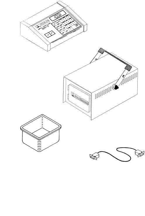
Control Unit
Sample Chamber
Sample Pans (4)
Control Unit/Chamber
Interface Cable
Figure 1. Gauge Parts
Model 3241 Series |
1-3 |

Unpacking and Inspection
Unpacking
Upon receipt of the gauge from the factory, perform a complete inspection and inventory. If the shipping case or any other part of the container is damaged contact the shipper immediately.
Save the box and any packing material for possible shipment of the gauge to another location or back to the factory.
Inspection
After removal from the transport case from the cardboard box, check to see if the following have been included (the first four are shown in Figure 1 on the previous page).
Control Unit – provides the operator interface to the system. The console contains the keypad, display and the microprocessor used to process the sample data.
Sample Chamber – contains the radioactive source, the detectors and the high voltage electronics used for measuring the asphalt content of the sample.
Sample Pans (4) – used to hold an exact amount of asphalt for testing. Four pans are supplied with the gauge.
Control Unit/Chamber Interface Cable – connects the console to the sample chamber.
Documentation (manual of operation and instruction; source certificate; data sheet; transportation guide).
Power Adapter – connects the gauge to a 115/230 VAC, 50/60 Hz power source.
Power Adapter (DC Charger).
Optional Serial Printer connects to the control unit for printing sample data.
Water Resistant Transport Case – a DOT-approved shipping container for the sample chamber and control unit.
1-4
Serial Interface Cable (optional accessory) connects the gauge to a printer or computer.
Lift the gauge from the case and inspect the outside surface for damage. Check the lock on the sample chamber. Make sure the keys fit the lock. Return the gauge to the transport case.
If the gauge appears to be damaged notify the carrier and your Troxler representative immediately.
Model 3241 Series |
1-5 |

Site Selection
When choosing a gauge location site, take into consideration the ambient temperature and location of power outlets, large objects and any other nuclear gauges.
Ensure that the room where the gauge is to be located is well ventilated and does not experience abrupt temperature or humidity changes.
Place the gauge on a level, sturdy surface.
Install the gauge with the control unit within reach of the operator's workstation and the sample chamber, connected to the control unit, readily accessible for sampling. The background count will account for any external hydrogen sources (Chapter 3: Operating the Gauge). If the system is moved or objects containing hydrogen and/or larger objects are moved near the sample chamber after taking the background count, a new background count should be taken.
Do not stand close to the sample chamber due to possible measurement effects and radiation safety.
The line voltage should not vary by more than 10%.
The ambient temperature should be between 10 and 33 °C (50 - 91 °F), and the relative humidity should be between 20 and 90 percent.
The gauge must be installed at least ten meters (33 feet) from any other nuclear gauge.
Do not expose the gauge to open flames, dust, direct sunlight, or ammonia and other corrosive fumes.
1-6

Chapter 2:
Theory of Operation
This chapter covers the following topics and tasks:
Operating principles
Model 3241 Series |
2-1 |

Theory
The Model 3241 Series Asphalt Content Gauges measure the amount of asphalt (bitumen) in a bituminous mixture by determining the hydrogen content of the material. The amount of asphalt and the amount of moisture can be related to hydrogen content since both contain hydrogen.
In all 3241 configurations, the fast neutrons emitted are thermalized (slowed) by the hydrogen in the asphalt. The Helium-3 detectors located in the gauge detect the slowed neutrons, since helium-3 detectors are insensitive to fast neutrons. The thermalized neutrons are counted over time and this “count” is proportional to the asphalt content of the sample.
2-2

Chapter 3:
Operating the Gauge
This chapter covers the following topics and tasks:
First-time setup
Taking background counts
Preparing samples
Taking measurements
Model 3241 Series |
3-1 |

Turning the Gauge On
Figure 2 shows all 3241 connections. Connect the sample chamber to the control unit with the main interface cable. Connect the power adapter to the control unit and a 120 VAC outlet.
Figure 2. 3241 Connections
3-2
Turn the gauge on by pressing ON .
|
|
|
|
After the RAM test the gauge will enter the 120-second Self Test. In this mode the version number and customer name are displayed. After the test the display will be:
|
|
|
|
The second line displays the time and date. The third line displays the count time. The last line displays the current enabled calibration.
Model 3241 Series |
3-3 |

Setting Parameters
After unpacking and turning “On” the gauge, several parameters can be initialized. These parameters usually do not require changing and include the count time, time/date, and company name.
Setting the Count Time
Press TIME for the display:
|
|
|
|
To accept the displayed count time, press ENTER . To change the displayed count time, press YES .
|
|
|
|
Make the selection by pressing the number that corresponds to your selection. The display will return to the Ready mode.
NOTE
The longer the count time the better the measurement precision.
3-4

Setting the Time/Date
Press SHIFT and 9 for the Special menu. The display will be:


To select this feature, press 4 .
The Time/Date function is a restricted function and requires an access code for operation. This is to ensure that the time and date are not changed by unauthorized personnel.
Input the access code and press ENTER . The display will be:
|
|
|
|
To accept the displayed date, press NO .
To change the date, press YES .
Select the format to be used: dd/mm/yy or mm/dd/yy.
Input the new date and press ENTER . To change the time, repeat the above procedure.
Model 3241 Series |
3-5 |
Changing the Customer Name
The gauge may be programmed to display your name or any other message (not to exceed 16 characters) during the powerup / self-test stage.
Press SHIFT and 9 for the Special menu. The display will be:


Scroll through the menu options by pressing YES twice. Select
Customer Name by pressing 7 .
|
|
|
|
To change the customer name, press YES .
The Customer Name function is a restricted function and requires an access code for operation. This is to ensure that the name/message is not changed by unauthorized personnel.
Input the access code and press ENTER . The display will be:
|
|
|
|
To scroll up through the letters, press SHIFT . To scroll down through the letters, press TIME .
To select the letter and move to the next position, press YES . Complete the operation by pressing ENTER .
3-6
Taking Background Counts
Prior to performing any testing, measuring, or calibrating with the gauge, take a background count. The background count adjusts for changes in the gauge environment and location.
The Model 3241 gauge is influenced by external sources of hydrogen. Once a background count is made, do not change the surrounding sources of large hydrogen content (e.g., draining a water bath, moving large containers of liquids). Take a new background count if changes occur or are suspected. During and after a background count the test samples should not be within 1 meter (3 feet) of the sample chamber.
The neutron source used in the gauge is Americium241:Beryllium and has a half-life of 432 years (or will undergo a natural decay of 0.2% per year). The background count also adjusts for source decay.
Press BKG for the display:
|
|
|
|
To take a new background count, press YES .
Prepare the sample chamber as instructed and press START .
After the count is complete and acceptable, press YES . To take another background count, press NO .
Model 3241 Series |
3-7 |

Preparing Samples
NOTE
Prior to measuring asphalt content, the gauge must contain a calibration corresponding to the asphalt samples to be tested (see Chapter 4:). The percent
(%) asphalt of the test samples must be within the range of the gauge calibration (see the example on page 4-3).
To prepare measurement samples:
1.Obtain the weight of an empty sample pan using an accurate balance scale or electronic scale. Record the pan weight.
2.Partially fill (1/3 full) the pan with the asphalt mix. Lightly tamp the mix with a spoon or spatula. Do not pack the material with a press or hammer.
3.Continue adding hot asphalt in layers, settling and tamping each layer until the pan is full and the asphalt is above the pan top. The asphalt sample should be level with the top of the pan, so place a piece of wax paper over the asphalt and press down on the sample with a wooden board or other flat object.
4.Remove the wax paper and place the full sample pan on the scale and obtain the weight. Record the value.
5.Repeat the above procedure for each sample. Make sure each sample has the same weight (±4 g).
6.Take a measurement as described the following section.
7.Upon measurement completion, remove the asphalt from the sample pan by reheating the pan in an oven. Turn the pan upside down and lightly tap on the bottom. Do not dent the bottom of the pan!
3-8
Taking a Measurement
NOTE
Ensure measurement consistency by marking the sample pans so they are inserted into the chamber the same way eat time the pan is used.
Place the asphalt sample into the test chamber and close the door.
If the Pan Weight Display function is enabled, the gauge will request the weight of the empty sample pan and the weight of the pan containing asphalt (see page 7-16).
Enable the appropriate mix calibration by pressing CALIB .
Press START to begin the measurement sequence. The display will be:


Input the recorded empty sample pan weight and press ENTER .
|
|
|
|
Make sure the unknown % asphalt content sample is the same weight as the calibration samples (±8 g) for the mix being tested.
Model 3241 Series |
3-9 |

Press START for the display:
|
|
|
|
The gauge will count down as the asphalt content measurement is obtained. After the count time has elapsed, the results will be displayed. For storing results, refer to Chapter 5.
3-10

Chapter 4:
Calibrations
This chapter covers the following topics and tasks:
Preparing calibration samples
Performing calibrations
Model 3241 Series |
4-1 |

Equipment Needed
In order to obtain precise asphalt content measurements, use a consistent method of sample preparation. Using the same approved equipment for preparing each sample helps ensure the best possible results.
Necessary Equipment
The following equipment will be needed during calibration and test sample preparation:
Balance/Electronic scale readable to 1 g (0.002 lb).
Drying oven, capable of heating to 177 C (350 F).
Two 76 x 30 x 6 cm (30 x 12 x 2.5 in.) stainless steel utility pans.
(2) 41 cm (16 in.) stainless steel mixing bowls.
Steel straightedge, approximately 20 cm (8 in.) long.
Plywood or metal plate having an area slightly larger than the sample pans.
Thermometer with temperature range of 10 to 260 C (50 to 500 F).
Assorted spoons, spatulas, heat resistant gloves, etc.
Suggested Equipment
The following equipment will aid mixing and sample preparation:
Large commercial grade electric blender with a mixing bowl capable of holding a sample weighing up to 10 kg (22 lb).
Heated asphalt reservoir with temperature control.
4-2
 Loading...