

TROXLER 3216 User Manual

Instruction Manual
MODEL 3216
ROOF MOISTURE
GAUGE
Troxler Electronic Laboratories, Inc.
3008 Cornwallis Rd. · P.O. Box 12057
Research Triangle Park, NC 27709
Phone: 1.877.TROXLER
Outside the USA: +1.919.549.8661
Fax: +1.919.549.0761
www.troxlerlabs.com

Troxler Gauges are protected by U.S.
and foreign patents
Copyright © 1981 - 2006
Troxler Electronic Laboratories, Inc.
All Rights Reserved
No part of this manual may be reproduced or
transmitted in any form or by any means, electronic
or mechanical, including photocopying, recording,
or information storage and retrieval systems, for
any purpose without the express written permission
of Troxler Electronic Laboratories, Inc.
PN 103367
October 2006
Edition 4.1

TROXLER SERVICE CENTERS
Troxler Corporate Headquarters
3008 Cornwallis Road
Research Triangle Park, NC 27709
Phone: 1.877.TROXLER (1.877.876.9537)
Outside the U.S.A.: +1.919.549.8661
P.O. Box 12057
Fax: +1.919.549.0761
Web: www.troxlerlabs.com
Phone: 1.877.TROXLER (1.877.876.9537)
Technical Support
E-mail: TroxTechSupport@troxlerlabs.com
Midwestern Branch Office
1430 Brook Drive
Downers Grove, IL 60515
Fax: 630.261.9341
Western Regional Branch Office
11300 Sanders Drive, Suite 7
Rancho Cordova, CA 95742
Fax: 916.631.0541
Southwestern Branch Office
2016 East Randol Mill Road
Suite 406
Arlington, TX 76011
Fax: 817.275.8562
Florida Service Center
2376 Forsyth Road
Orlando, FL 32807
Fax: 407.681.3188
Canadian Branch Office
7125 Pacific Circle, Unit 13
Mississauga, Ontario L5T-2A5
Canada
Fax: 905.564.7092
Troxler European Subsidiary
Troxler Electronics GmbH
Gilchinger Strasse 33
D.82239 Alling nr.
Munich, Germany
Phone: ++49.8141.71063
Fax: ++49.8141.80731
E-mail: troxler@t-online.de

NOTES

TABLE OF CONTENTS
I. INTRODUCTION AND SPECIFICATIONS
II. OPERATING INSTRUCTIONS
III. FIELD MEASUREMENTS
IV. SENSITIVITY DATA ................. 4-1
V. PERIODIC MAINTENANCE
VI. SERVICE
I-A. Introduction . . . . . . . . . . . . . . . 1-1
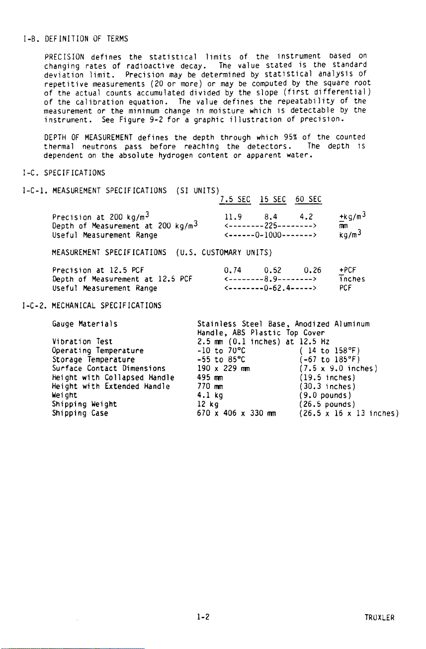
I-B. Definition of Terms . . . . . . . . . . . 1-2
I-C. Specifications . . . . . . . . . . . . . . 1-2
II-A. Getting Acquainted . . . . . . . . . . . . 2-1
II-B. Control Functions and Operations . . . . . 2-1
II-C. Test Functions . . . . . . . . . . . . . . 2-2
III-A. Data Collection . . . . . . . . . . . . . 3-1
III-B. Manual Analysis of Data . . . . . . . . . 3-4
III-C. Computer Aided Analysis of Data . . . . . 3-11
III-D. Vertical Wall Measurements . . . . . . . . 3-12
V-A. Battery Charging . . . . . . . . . . . . . 5-1
V-B. Cleaning ................. 5-1
V-C. Internal Condensation . . . . . . . . . . 5-1
V-D. Gauge Disassembly . . . . . . . . . . . . 5-2
V-E. Leak Test Procedure . . . . . . . . . . . 5-2
VI-A. Equipment Required . . . . . . . . . . . . 6-1
VI-B. Gauge Electronics . . . . . . . . . . . . 6-2
VI-C. Statistical Stability . . . . . . . . . . 6-5
VI-D. Troubleshooting Hints . . . . . . . . . . 6-7
VI-E. Service Centers . . . . . . . . . . . . . 6-8
VII. PARTS LIST
VIII. THEORY OF MEASUREMENT
IX. FACTORY CALIBRATION
X. RADIATION THEORY AND SAFETY
VII-A. Replacement Parts . . . . . . . . . . . . 7-1
VII-B. Accessories . . . . . . . . . . . . . . . 7-1
VIII-A. Neutron Radiation and Matter . . . . . . . 8-1
VIII-B. Moisture Geometry . . . . . . . . . . . . 8-3
IX-A. Moisture Calibration . . . . . . . . . . . 9-1
IX-B. Moisture Performance Parameters . . . . . 9-2
X-A. Radiation Theory . . . . . . . . . . . . . 10-1
X-A-1. Atomic Structure . . . . . . . . . . . . . 10-1
X-A-2. Radiation Theory . . . . . . . . . . . . . 10-2
X-A-3. Radiation Terminology . . . . . . . . . . 10-2
X-B-1. Radiation Statistics . . . . . . . . . . . 10-2
X-B. Radiation Safety . . . . . . . . . . . . . 10-3
X-B-1. Types of Radiation . . . . . . . . . . . . 10-3
X-B-2. Limiting Exposure . . . . . . . . . . . . 10-4
X-B-4. Monitoring Radiation . . . . . . . . . . . 10-5
i

Table of Contents (cont'd)
X-B-4. 3216 Radiation Profile . . . . . . . . . . 10-6
X-B-5. Source Encapsulation . . . . . . . . . . . 10-7
X-B-6. Emergency Procedures . . . . . . . . . . . 10-7
XI. TRANSPORTATION AND SHIPPING
APPENDIX A
XI-A. Requirements . . . . . . . . . . . . . . . 11-1
XI-A-1. Certificate of Competent Authority . . . . 11-1
XI-A-2. Results of Type A Package Testing . . . . 11-2
XI-A-3. Emergency Response Sheet . . . . . . . . . 11-2
XI-A-4. Emergency Response Telephone Number . . . 11-2
XI-A-5. Labeling Requirements . . . . . . . . . . 11-2
XI-A-6. "Bill of Lading" Requirements . . . . . . 11-2
XI-A-7. Locking or Sealing of Package . . . . . . 11-3
XI-A-8. Inspection of Package Prior to Shipment . 11-3
XI-A-9. Accident Notification Requirements . . . . 11-3
XI-A-10 Hazmat Training . . . . . . . . . . . . . 11-3
XI-B. Shipping Forms . . . . . . . . . . . . . . 11-3
BASIC Listing for Standard Deviation . . . . . . . AI
Sample Output from Standard Deviation Program . . . AII
ii

LIST OF ILLUSTRATIONS
Figure Description Page
3-1 Gridded Roof Plan 3-3
3-2 Roof Measurement Data 3-3
3-3 Histogram of Sample Data 3-4
3-4 Normal Distribution With
Confidence Limits
3-5 Normal Distribution Overlaying
Histogram
3-6 Standard Deviation for Grouped
Data
3-7 Percent Moisture Correlation Graph
Data
3-8 Graphic Interpretation of Roof
Survey
3-9 Computer Aided Plot 3-11
5-1 Leak Test Analysis Form 5-3
6-1 Interior Layout 6-3
6-2 Block Diagram of Gauge Electronics 6-4
6-3 Statistical Test Data 6-5
8-1 Neutron Interaction Data 8-3
8-2 Effect of Neutron Source-Detector
Distance
8-3 Effect of Moisture on Depth of
Measurement
9-1 3216 Calibration Data 9-4
9-2 Graphic Interpretation of Moisture
Calibration
10-1 Diagram of an Atom 10-1
10-2 Variation of Radioactive Emission 10-3
10-3 Effect of Distance on Exposure 10-4
10-4 3216 Radiation Profile 10-6
11-1 Sample Intra-company "Bill of
Lading"
11-2 Sample Common Carrier "Bill of
Lading"
11-3 Sample Shipper's Declaration of
Dangerous Goods
11-4 Sample Federal Express Form 11-7
3-5
3-6
3-7
3-8
3-9
8-4
8-5
9-6
11-4
11-5
11-6
iii

This page intentionally blank
iv


I-C-3. CALIBRATION SPECIFICATIONS
Number of Standards 2
Accuracy of Standards ±4.0%
I-C-4. RADIOLOGICAL SPECIFICATIONS
Neutron Source 1.48 ± 10% GBq
Source Form Stainless steel,
Source Classification ANSI-C54444
per ANSI N542-1977
Shielding Lead and Polyethylene
Maximum Surface Dose Rates See Radiation Profile on
Shipping Case DOT 7A, Type A, Yellow II
Special Form Approval Am-241, SPECIAL FORM
Gauge Classification per ANSI-54-685-685-R2
ANSI N538-1979
I-C-5. ELECTRICAL SPECIFICATIONS
Time Accuracy and Stability ± 0.005% ± 0.0002%/°C
Power Supply Stability ± 0.01%/°C
Battery Capacity 14 W-hr
(40 ± 10% mCi)
70,000 n/sec yield,
TEL A-102451
encapsulated
page 10-6
Label, 0.1 TI
Certificate GB:SFC 7
Charge Source 115/230 V, 50-60 Hz
Battery Recharge Time
AC Charger 14 hr
DC Charger 3 hr
LCD 4 digits
Largest Number Displayable 9999
Count Registers 1
Power Consumption 0.08 W
Power Consumption after 0.001 W
Automatic Battery Cutoff
Battery packs are fully protected against overcharge and
overdischarge. Low Battery alarm is indicated on the display
several hours prior to automatic cutoff.
TROXLER 1-3
or 12-15 VDC


III-A-2. LAYOUT GRID ON ROOF
The grid pattern (at the selected size) must be laid out
on the roof. Paint, strings, marked ropes, or other
methods can be used to define the grid intersections on
the roof.
One popular method is to use two marked ropes, placed
parallel on opposite sides of the roof. A third marked
rope is stretched between the two parallel ropes. With
spray paint can spot the roof at each marking on the
rope. The "marking stick" listed in the Accessories
Parts List (Section VII-B) is especially useful for this
purpose.
III-A-3. DRAWING OF ROOF PLAN
Make a scaled drawing of the roof's top view. Note on
this drawing all roof structures (drains, heating and
air conditioning units, ventilation shafts, etc.). If
there are no roof structures or other details that
indicate building orientation, then note the north
orientation on the drawing.
Any roof structures the user wishes included on a plot
must also by shown on the roof plan.
III-A-4. COLLECT MEASUREMENT DATA
Set the POWER/TIME switch to the desired accumulation
time period. Use the gauge to make a measurement count
at each grid intersection. Record this count at the
correct position.
III-A-5. CUT CORE SAMPLES
Nuclear gauges register relative hydrogen levels. If
absolute moisture levels are needed, one must correlate
count rates and actual moisture levels. Correlation is
normally done via core samples.
The core samples should be chosen to include the widest
range of count rates possible. The roof plan count rate
data will be useful in choosing where to cut core
samples. If a limited number of core samples are to be
cut, then they should be made at sites (determined from
the count data) that indicate a transition from dry to
wet.
3-2 TROXLER


 Loading...