

Page 1

Manual of Operation and Instruction
Model 3451
Enhanced
RoadReader™ Plus
Surface Moisture-Density Gauge
NOTE
The Model 3451 Enhanced RoadReader Plus is equipped with a
global positioning system (GPS) receiver. If the gauge is moved
a long distance between uses, the GPS system must be allowed
to initialize. In some instances, initialization may take as long as
30 to 45 minutes from the time the gauge is powered on with the
GPS enabled. Note also that the gauge must be positioned such
that the GPS receiver can receive signals from the GPS
satellites (see page 1–5 for more information). If the GPS does
not initialize within 45 minutes, contact your Troxler
representative.
Troxler Electronic Laboratories, Inc.
3008 Cornwallis Rd. P.O. Box 12057
Research Triangle Park, NC 27709 U.S.A.
Phone: 1.877.TROXLER
Outside the USA: +1.919.549.8661
Fax: +1.919.549.0761
www.troxlerlabs.com
Page 2

Troxler gauges are protected by U.S. and foreign patents
Copyright 2004 – 2009
Troxler Electronic Laboratories, Inc.
All Rights Reserved
No part of this manual may be reproduced or transmitted in any
form or by any means, electronic or mechanical, including
photocopying, recording, or information storage and retrieval
systems, for any purpose without the express written permission of
Troxler Electronic Laboratories, Inc.
Bluetooth is a registered trademark of the Bluetooth Special Interest
Group (SIG).
Federal Express is a registered trademark of the Federal Express
Corporation.
Intermec is a registered trademark of Intermec Technologies Corp.
Magnalube-G is a registered trademark of Carleton-Stuart
Corporation.
Microsoft, Windows, Windows XP, Excel, and ActiveSync are
registered trademarks of Microsoft Corporation.
Pentium is a registered trademark of Intel Corporation.
RoadReader is a trademark of Troxler Electronic Laboratories, Inc.
WD-40 is a registered trademark of the WD-40 Company.
PN 110399
July 2009
Edition 3.1
ii
Page 3

TROXLER SERVICE CENTERS
Troxler Corporate Headquarters
3008 Cornwallis Road
P.O. Box 12057
Research Triangle Park, NC 27709
Phone: 1.877.TROXLER (1.877.876.9537)
Outside the U.S.A.: +1.919.549.8661
Fax: +1.919.549.0761
Web: www.troxlerlabs.com
Technical Support
Phone: 1.877.TROXLER (1.877.876.9537)
E-mail: TroxTechSupport@troxlerlabs.com
Florida Service Center
2376 Forsyth Road
Orlando, FL 32807
Fax: 407.681.3188
Texas Service Center
2016 East Randol Mill Road
Arlington, TX 76011
Fax: 817.275.8562
Illinois Service Center
1430 Brook Drive
Downers Grove, IL 60515
Fax: 630.261.9341
Northern California Service Center
11300 Sanders Drive, Suite 7
Rancho Cordova, CA 95742
Fax: 916.631.0541
Troxler European Subsidiary
Troxler Electronics GmbH
Gilchinger Strasse 33
D.82239 Alling nr. Munich, Germany
Phone: ++49.8141.71063
Fax: ++49.8141.80731
E-mail: troxler@t-online.de
To locate an independent, Troxler-authorized service
partner near you, call 1.877.TROXLER
(1.877.876.9537).
Suite 406
NOTE
Model 3451 iii
Page 4

HOW TO USE THIS MANUAL
Congratulations on the purchase of the Troxler Model 3451
Enhanced RoadReader Plus. Troxler continues the proven
technology of its 3400 Series surface moisture-density gauges with
the Troxler Model 3451 Enhanced RoadReader Plus.
The Model 3451 Manual of Operation and Instruction contains
information on safely using this gauge. Also included in this manual
are safety warnings, gauge setup, troubleshooting, and general
maintenance.
iv
Page 5

CONVENTIONS USED IN THIS MANUAL
Throughout this manual, symbols and special formatting are used to
reveal the purpose of the text as follows:
WARNING
Indicates conditions or procedures that, if not followed
correctly, may cause personal injury.
CAUTION
Indicates conditions or procedures that, if not followed
correctly, may cause equipment damage.
NOTE
Indicates important information that must be read to
ensure proper operation.
Button Angle brackets and a different typestyle indicate a
button or character (number or letter) to press on
the handheld personal digital assistant (PDA) or on
the keyboard of a personal computer (PC) when
using the Data Manager software provided with the
gauge. For example, “Press Start” means to press
the button labeled Start.
Display A different typestyle is used in text to indicate
information or messages displayed on the PDA or
computer.
Diamonds indicate a list of things needed (such as
equipment) or things to know.
Check marks indicate the performance of an action.
With lists of check marks, follow the instructions in
the order of the check marks.
Triangles indicate that more than one option is
available. Carefully select the option that applies.
Model 3451 v
Page 6

NOTES
vi
Page 7

TABLE OF CONTENTS
CHAPTER 1. INTRODUCTION TO THE MODEL 3451
Introduction................................................................................... 1–2
Global Positioning System Accuracy ........................................... 1–5
Gauge Parts and Accessories........................................................1–8
Unpacking and Inspection .......................................................... 1–11
CHAPTER 2. THEORY OF OPERATION
Density..........................................................................................2–2
Moisture........................................................................................ 2–3
Thin Layer .................................................................................... 2–5
Calibration .................................................................................... 2–6
CHAPTER 3. GETTING STARTED
Model 3451 Illustration ................................................................ 3–3
Source Rod Positions.................................................................... 3–5
Before Using the Gauge and PDA................................................ 3–6
Turning the Gauge and PDA On................................................... 3–8
Troxler Menu.............................................................................. 3–10
RoadReader Plus Main Menu..................................................... 3–16
Project Files................................................................................ 3–19
Status........................................................................................... 3–24
CHAPTER 4. USING THE GAUGE
Taking a Standard Count .............................................................. 4–2
Preparing a Test Site..................................................................... 4–7
Taking Measurements................................................................. 4–10
CHAPTER 5. SETUP AND TARGET MENUS
Gauge Setup Menu ....................................................................... 5–2
Target.......................................................................................... 5–14
Model 3451 vii
Page 8

TABLE OF CONTENTS (Continued)
CHAPTER 6. ADJUSTING MEASUREMENTS
Calibration Offset..........................................................................6–2
Special Calibration......................................................................6–14
CHAPTER 7. USING DATA MANAGER
Introduction...................................................................................7–3
System Requirements....................................................................7–4
Starting the Data Manager Program..............................................7–5
Manage Project Data .....................................................................7–6
View Project Configuration.........................................................7–11
Recover Projects..........................................................................7–19
APPENDIX A. RADIATION THEORY AND SAFETY
Radiation Theory..........................................................................A–2
Radiation Safety...........................................................................A–5
Regulatory Requirements...........................................................A–14
Gauge Use Precautions...............................................................A–17
3451 Radiation Profile................................................................A–18
APPENDIX B. 3451 SPECIFICATIONS
Measurement Specifications.........................................................B–2
Radiological Specifications..........................................................B–5
Electrical Specifications............................................................... B–6
Mechanical Specifications............................................................ B–7
APPENDIX C. TROUBLESHOOTING AND SERVICE
Diagnostics Menu ......................................................................... C–2
Troubleshooting............................................................................C–9
Batteries...................................................................................... C–24
Replacing Fuse...........................................................................C–26
Mechanical Maintenance............................................................ C–27
Replacement Parts...................................................................... C–29
Returning the Gauge for Service................................................ C–32
viii
Page 9

TABLE OF CONTENTS (Continued)
APPENDIX D. TRANSPORTATION AND SHIPPING
U.S. Shipping Requirements........................................................ D–2
Canadian Shipping Requirements................................................ D–5
APPENDIX E. STANDARD COUNT LOG
APPENDIX F. UNIT CONVERSION
Measurement Units.......................................................................F–2
Radiological Units ........................................................................ F–2
APPENDIX G. SPECIAL EUROPEAN CONSIDERATIONS
Declaration of Conformity........................................................... G–2
Safety Warnings........................................................................... G–3
INDEX
WARRANTY
Model 3451 ix
Page 10

LIST OF FIGURES
Figure
1–1 Model 3451 Parts and Accessories............................1–9
2–1 Effect of Moisture on Depth of Measurement...........2–4
3–1 Model 3451 Illustration .............................................3–3
3–2 Back Panel Details.....................................................3–4
3–3 Source Rod Positions.................................................3–5
3–4 Troxler Menu...........................................................3–10
3–5 Notes Screen............................................................3–10
3–6 Calculator.................................................................3–11
3–7 Intermec Launcher Display......................................3–12
3–8 Windows Desktop....................................................3–12
3–9 Return to Troxler Menu...........................................3–13
3–10 Battery Status Display .............................................3–17
3–11 RoadReader Plus Software Main Menu...................3–18
3–12 Project Menu............................................................3–20
3–13 New Project Setup Wizard, Page 1..........................3–20
3–14 Project File Selector.................................................3–22
3–15 Project Data Display................................................3–22
3–16 Project Erase Prompt ...............................................3–23
3–17 Gauge Tools Menu...................................................3–24
3–18 Gauge Status Menu..................................................3–24
3–19 View Status Display.................................................3–25
3–20 View Constants Display...........................................3–25
3–21 Source Decay Menu.................................................3–27
3–22 GPS Location Display.............................................3–28
4–1 Standard Menu...........................................................4–2
4–2 Standard Count Position ............................................4–3
4–3 Standard Count Results..............................................4–5
4–4 View Standard Screen................................................4–6
4–5 Drill Rod Assembly...................................................4–8
4–6 Marking the Test Area...............................................4–8
4–7 Entering Project Notes.............................................4–12
4–8 Count Results, Soil Mode........................................4–13
4–9 Count Results, Asphalt Mode..................................4–16
4–10 Gauge Positioned Around a Core Site.....................4–18
Title Page
x
Page 11

LIST OF FIGURES (Continued)
Figure
4–11 Gauge Positioned Over Designated Test Site..........4–19
4–12 Individual Count Results, Thin Layer Mode........... 4–20
4–13 Averaged Count Results, Thin Layer Mode............ 4–20
5–1 Change Settings Menu ..............................................5–2
5–2 Gauge Setup Menu....................................................5–2
5–3 View Setup Display................................................... 5–3
5–4 Set Units Menu.......................................................... 5–4
5–5 Mode Change Display...............................................5–6
5–6 Count Time Menu..................................................... 5–7
5–7 Enter Code Menu ...................................................... 5–8
5–8 Enter Customer Name Menu.....................................5–8
5–9 Change User Code Menu .......................................... 5–9
5–10 Depth Indicator Menu............................................. 5–10
5–11 Leak Test Menu.......................................................5–11
5–12 Leak Test Interval Menu......................................... 5–12
5–13 Leak Test Date Menu..............................................5–13
5–14 Target Menus ..........................................................5–15
5–15 Proctor Value Menu................................................ 5–15
5–16 Input Proctor Value Display.................................... 5–16
5–17 Proctor File Selector................................................ 5–17
6–1 Offset Menu .............................................................. 6–3
6–2 Wet Density Offset Select......................................... 6–4
6–3 Input Wet Density Offset .......................................... 6–4
6–4 Moisture Offset Select............................................... 6–5
6–5 Input True Percent Moisture .....................................6–7
6–6 Enter Moisture Offset File Name.............................. 6–7
6–7 Input Moisture Value from Gauge............................ 6–8
6–8 Input True Moisture .................................................. 6–8
6–9 Offset File Selector ................................................... 6–9
6–10 Moisture Offset Erase Prompt.................................6–11
6–11 Trench Offset Select................................................6–12
6–12 New Trench Offset Confirmation ........................... 6–13
6–13 Soil Special Calibration Menu................................ 6–15
6–14 Gauge Positioned Over Designated Test Site..........6–16
6–15 Input True Density ..................................................6–17
Title Page
Model 3451 xi
Page 12

LIST OF FIGURES (Continued)
Figure
6–16 Enter File Name.......................................................6–17
6–17 Special File Selector................................................6–18
6–18 Special Calibration Erase Prompt............................6–18
6–19 Enter Rod Position...................................................6–19
6–20 Taking Measurements Around a Core Site..............6–20
6–21 Thin Lift Special Calibration Menu.........................6–21
6–22 Input Top Layer Thickness......................................6–22
6–23 Input True Density...................................................6–24
6–24 Thin Layer Special Calibration Results...................6–24
6–25 Enter File Name.......................................................6–24
6–26 Thin Lift File Selector..............................................6–25
6–27 Thin Lift Special Calibration Erase Prompt.............6–25
6–28 Input Number of Averages ......................................6–27
7–1 Data Manager Main Menu.........................................7–5
7–2 Manage a Project Menu.............................................7–6
7–3 Connect PDA to PC Prompt ......................................7–8
7–4 View a Project Display..............................................7–8
7–5 Project Data Spreadsheet .........................................7–10
7–6 Print Active Project Menu .......................................7–11
7–7 Gauge Constants Display.........................................7–13
7–8 Project Setup Display...............................................7–14
7–9 Standard Counts Display .........................................7–14
7–10 Project Status Display..............................................7–16
7–11 Source Decay Display..............................................7–16
7–12 Stat Test Display......................................................7–18
7–13 Drift Test Display....................................................7–18
7–14 Recover Project Menu.............................................7–19
7–15 Connect Gauge to PC Prompt..................................7–20
A–1 Diagram of an Atom.................................................A–2
A–2 Effect of Distance on Exposure ................................A–7
A–3 Cleaning the Sliding and Fixed Blocks...................A–12
A–4 Model 3451 Gauge and Transport Case..................A–18
Title Page
xii
Page 13

LIST OF FIGURES (Continued)
Figure
C–1 Diagnostics Menu......................................................C–3
C–2 Stat Test Menu ..........................................................C–3
C–3 View Stat Co unts.......................................................C–4
C–4 Stat Test Results........................................................C–4
C–5 Review Stat Test .......................................................C–4
C–6 Drift Test Menu.........................................................C–6
C–7 View Drift Counts.....................................................C–7
C–8 Drift Test Results ......................................................C–7
C–9 Review Drift Test......................................................C–7
C–10 Replacing NiMH Battery Pack or Fuse...................C–25
D–1 Type A Package Testing Results.............................. D–4
Title Page
Model 3451 xiii
Page 14

LIST OF TABLES
Title Page
Table
1–1 GPS Position Accuracy..............................................1–7
A–1 Radiation Profile for Model 3451 Gauge................A–19
xiv
Page 15

ATTENTION 3451 GAUGE OWNER
This unit contains functions that require an ACCESS CODE.
This code must be entered before these functions may be used.
The ACCESS CODE for this gauge is:
4012
This page should be removed if the access code is not to be
distributed to other parties or users of this gauge.
Model 3451 xv
Page 16

NOTES
xvi
Page 17

CHAPTER 1
INTRODUCTION TO THE MODEL 3451
This chapter provides a brief overview of the Troxler Model 3451
Enhanced RoadReader Plus, as well as an explanation of the
global positioning system (GPS). This chapter also includes a list of
the gauge parts and accessories, and instructions for unpacking and
inspecting the gauge.
CONTENTS
Introduction................................................................................... 1–2
Global Positioning System Accuracy ........................................... 1–5
Gauge Parts and Accessories........................................................ 1–8
Unpacking and Inspection .......................................................... 1–11
1. INTRODUCTION
Model 3451 1–1
Page 18

INTRODUCTION
Troxler’s Model 3451 Enhanced RoadReader Plus combines the
impressive features of the Model 3450 RoadReader Plus with
advanced global positioning system (GPS) and wireless
technologies to provide unparalleled performance, flexibility, ease
of use, and operator safety.
Like the 3450 gauge, the Model 3451 incorporates the proven
capabilities of Troxler’s 3400 (moisture/density) and 4640 (thinlayer density) gauges in a single unit that can perform thin-layer,
backscatter, direct transmission, and moisture measurements. In
addition to the features found in the 3450 gauge:
The Model 3451 is controlled using a handheld personal digital
assistant (PDA), which allows the operator to stand away from
the gauge while operating it via Bluetooth wireless
communications.
An onboard GPS receiver enables the Model 3451 to store
precise GPS coordinates, along with the standard date and time
stamp, for each measurement.
The Data Manager PDA to PC Model 3451 for Windows XP
software included with the gauge enables the operator to collect
project data from the PDA or gauge on a personal computer
(PC), print project configuration information, and recover data
from the gauge in case of an emergency (such as the loss of the
PDA).
With the Model 3451, the operator can quickly and precisely
measure the moisture content and density of construction materials.
The gauge’s features include:
Three measurement modes (soil, asphalt, and thin layer) for
precise compaction control readings in most construction
materials:
Soil Mode: For moisture/density determinations in soil, soil-
stone materials in layers of 4 inches or greater.
Asphalt Mode: For density determinations in asphalt or
hardened concrete layers of 4 inches or greater.
Thin Layer Mode: For density determinations in asphalt layers
of less than 4 inches.
1–2
Page 19

Calibration offsets (wet density, moisture, and trench) and
special calibrations (soil and thin layer) to expand measurement
possibilities, and to enhance gauge readings on materials that
may fall outside the range of factory calibration.
Over 30 functions to facilitate all phases of testing compaction
on construction materials.
To preserve battery life, the gauge shuts down automatically
after five hours of inactivity.
The Model 3451 meets or exceeds all applicable American Society
of Testing and Materials (ASTM) standards (or corresponding
equivalent), including:
ASTM D-2950: Standard Test Method for Density of
Bituminous Concrete in Place by Nuclear Method.
ASTM D-6938: Standard Test Methods for In-Place Density
and Water Content of Soil and Soil-Aggregate by Nuclear
Methods (Shallow Depth)
NOTE
As of November 2006, ASTM D-6938 replaced ASTM
D-2922: Standard Test Methods for Density of Soil and
Soil-Aggregate in Place by Nuclear Methods (Shallow
Depth) and ASTM D-3017: Standard Test Method for
Water Content of Soil and Rock in Place by Nuclear
Methods (Shallow Depth).
Any licensing issues discussed in this manual are for the United
States. To purchase a Model 3451 in Canada, owners must obtain a
radioisotope license from the Canadian Nuclear Safety Commission
(CNSC). The owner should obtain copies of the AECB Regulations
and the Transportation of Dangerous Goods Act and Regulations
(TDG). For other countries, please consult your local regulatory
agency.
1. INTRODUCTION
Model 3451 1–3
Page 20

Owners are encouraged to require study of this manual before
allowing anyone to use the gauge. A potential hazard does exist if
improperly used. Appendices A and D, which cover radiological
safety, should be required reading for all users and potential users.
If these appendices are not completely understood, users should
seek assistance from Troxler, an appointed Troxler
representative, or others designated within the user's
organization.
Additional radiation safety information is available by attending a
Troxler Nuclear Gauge Training Course.
Before operating the Model 3451 gauge, users in European
countries must refer to Appendix G for special considerations,
additional safety warnings, and the Declaration of Conformity.
Since changes are made to local, state, and federal regulations on a
continuing basis, the owner/operator must maintain awareness of
current requirements. The responsibility for compliance ultimately
falls on the owner. An owner in the United States may also wish to
purchase and subscribe to Titles 10 and 49 of the Code of Federal
Regulations (CFR) in addition to applicable local/state regulations.
1–4
Page 21

GLOBAL POSITIONING SYSTEM ACCURACY
As described earlier, the Model 3451 is equipped with a global
positioning system (GPS) receiver that provides accurate
information on the location (latitude and longitude) of the gauge.
This information is stored with each gauge measurement. The GPS
receiver used in the Model 3451 has Wide Area Augmentation
System (WAAS) capabilities, which provides accuracy to within 3 m
(10 ft). However, the accuracy is dependent upon the user’s location
and other factors as described below.
The global positioning system (GPS) is a satellite-based navigation
system that consists of 24 satellites and a network of ground stations
that monitor and control those satellites. The satellites orbit the earth
at an altitude of approximately 11,000 miles, and constantly
transmit signal information back to earth. A GPS receiver uses this
information to determine its location.
To determine its latitude and longitude, a GPS receiver must receive
the signals from at least three satellites.
On average, the receiver used in the Model 3451 gauge is accurate
to with 15 m (approximately 50 ft) when receiving GPS data alone.
However, the WAAS capabilities can increase the accuracy to
within 3 m (10 ft), as shown in Table 1–1.
The accuracy of GPS information can be affected by a number of
atmospheric forces and other conditions. The Wide Area
Augmentation System (WAAS) corrects for these factors by placing
GPS receivers at 25 known, precisely surveyed locations, called
reference stations, across the United States. The reference stations
determined a measured distance to each satellite using the signals
received from the satellites. For each satellite, the stations compare
the measured distance to the actual range (as calculated from its
known position) to determine a differential correction for each
satellite
1. INTRODUCTION
Model 3451 1–5
Page 22

Two master stations, located on either coast, collect data from the
reference stations to create a GPS correction message. This message
is then broadcast through two geostationary satellites that are in a
fixed position over the equator. The GPS receiver applies the
correction factors contained in the correction message to increase
the accuracy of its measurements.
Note that the signals from the WAAS satellites may not be available
to gauge users in locations where trees, mountains, and other large
objects obstruct the view of the horizon. On other occasions, the
GPS receiver may not be able to access the signals from the three
satellites required to determine a position. As noted earlier, the
gauge stores location information with the results of each
measurement. The measurement display also denotes the quality of
the location fix as follows:
If WAAS information is available during a gauge measurement,
the fix quality for that measurement will be denoted as DGPS
fix.
If a GPS location is determined, but the WAAS information is
unavailable, the fix quality will be denoted as GPS fix.
If the GPS receiver cannot determine a location, the latitude and
longitude will be denoted as 0.
NOTE
The Wide Area Augmentation System (WAAS) is
currently functional only in the United States.
NOTE
If the gauge is moved a long distance between uses, the
GPS system must be allowed to initialize. In some
instances, initialization may take as long as 30 to 45
minutes from the time the gauge is powered on with the
GPS enabled. Note also that the gauge must be
positioned such that the GPS receiver can receive signals
from the GPS satellites as described above. If the GPS
does not initialize within 45 minutes, contact your
Troxler representative.
1–6
Page 23

Table 1–1. GPS Position Accuracy
Quality of
GPS Data
1. INTRODUCTION
Accuracy Fix Quality
GPS reading
with WAAS
GPS reading
without WAAS
No GPS reading N/A
Within 3 m
(10 ft)
Within 15 m
(50 ft)
DGPS fix
GPS fix
Latitude and longitude
displayed as 0.
Model 3451 1–7
Page 24

GAUGE PARTS AND ACCESSORIES
Figure 1–1 shows the gauge and its accessories.
1. The Gauge is the portable instrument containing electronic
modules, a cordless serial adapter with Bluetooth wireless
technology, a rechargeable battery pack, detectors, and the
radioactive sources.
2. The Intermec
provides the operator interface with the gauge. Included with
the PDA are a stylus, a rechargeable battery pack, a serial cable,
a dc adapter used to charge the PDA from an automobile
cigarette lighter, a universal ac adapter and ac power cord used
to charge the PDA from an ac outlet, a Quick Start Guide, and a
Pocket PC Companion CD containing Microsoft ActiveSync
software.
3. The Transport Case for the Model 3451 is a Type A package.
Always use a Type A package to ship the Model 3451.
4. The Reference Standard Block provides a measurement
standard for standard counts. It is also used during stability and
drift tests.
5. The Scraper Plate/Drill Rod Guide is used to prepare the test
site and to guide the drill rod when preparing the source rod
hole for direct transmission measurements.
6. The Drill Rod is used to drill holes for direct transmission
measurements. Do not use the gauge source rod to drill holes.
7. The Extraction Tool provides leverage to remove the drill rod
from soil materials.
8. The Model 3451 Manual of Operation and Instruction details
how to use the gauge. Both the manual and the Transportation
Guide discuss radiation safety and gauge shipping concerns.
9. The AC Charger and DC Adapter are used to charge the gauge
batteries. The ac charger accepts 110 (220 and European
optional) V ac, 50/60 Hz and supplies 12 V dc. The dc adapter
allows recharging from an automobile cigarette lighter.
10. The Data Manager PDA to PC Model 3451 for Windows XP
software includes tools for retrieving and managing project data
from the PDA or gauge. This software is provided on CD-ROM
(not shown).
700 Series Color Mobile Computer, or PDA,
1–8
Page 25
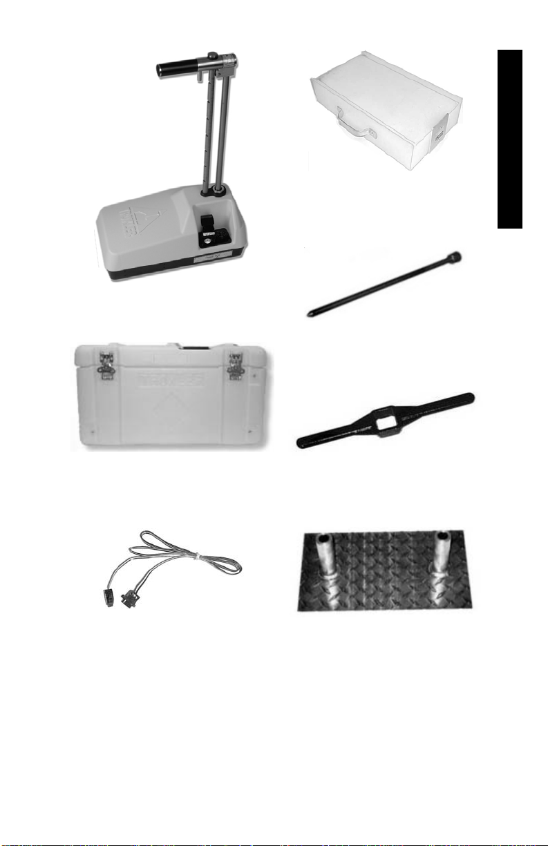
1. INTRODUCTION
MODEL 3451 GAUGE
TRANSPORT CASE
PN 110422.3451
REFERENCE STANDARD BLOCK
PN 107830
DRILL ROD
PN 100421
EXTRACTION TOOL
PN 103680.1000
SERIAL CABLE,
PN 110708
(GAUGE TO PC)
SCRAPER PLATE/
DRILL ROD GUIDE
PN 107795
Note: Images not to scale.
Figure 1–1. Model 3451 Parts and Accessories
Model 3451 1–9
Page 26

AC CHARGER
PN 110403
(FOR GAUGE)
INTERMEC 700 SERIES
MOBILE COMPUTER (PDA)
PN 110687
DC (AUTO) ADAPTER
UNIVERSAL AC ADAPTER
PN 104156
(FOR GAUGE)
PN 110691
&
AC POWER CORD
PN 110690
(FOR PDA)
DC (AUTO) ADAPTER
PN 110692
(FOR PDA)
SERIAL CABLE ASSEMBLY
PN 110693
(PDA to PC)
Note: Images not to scale.
Figure 1–1. Model 3451 Parts and Accessories (Continued)
1–10
Page 27

UNPACKING AND INSPECTION
Troxler recommends that the operator wear a dosimeter while
working with the gauge. Upon receipt of the gauge from the factory,
perform a complete inspection and inventory. If the shipping case
and/or any other part or accessory appears damaged, notify the
carrier and your Troxler Representative immediately.
Check the shipping cases for the items listed on page 1–8. In
addition, the shipping cases should contain the Gauge Warranty and
a Source Certificate.
For shipping to another location or back to the factory, save the
boxes and any packing material. For shipping instructions and
regulations, please see Appendix D.
NOTE
Charge the 3451 batteries for 2.5 hours prior to initial
use. Install the PDA battery pack and charge the PDA as
directed in the Quick Start Guide provided with the unit.
NOTE
If the PDA battery pack is completely discharged when
the gauge and accessories are unpacked, charge the PDA
for 4 hours before use. Refer to the Quick Start Guide
provided with the unit for instructions on installing and
charging the battery pack.
Lift the gauge from the transport case and inspect the outside
surface for damage. Check the lock on the source rod handle and
make sure the keys fit. Remove the lock, release the trigger, and
check the source rod operation. It should move up and down with
little effort. Return the gauge to the transport case.
1. INTRODUCTION
Model 3451 1–11
Page 28

NOTES
1–12
Page 29

CHAPTER 2
THEORY OF OPERATION
This chapter provides a brief description of the theory of operation
of the Troxler Model 3451 Enhanced RoadReader Plus. The direct
transmission and backscatter modes of operation are illustrated,
along with an explanation of the cesium-137 source,
americium-241:beryllium source, and detector geometry.
CONTENTS
Density.......................................................................................... 2–2
Moisture........................................................................................ 2–3
Thin Layer .................................................................................... 2–5
Calibration .................................................................................... 2–6
Offsets .................................................................................... 2–6
2. THEORY OF OPERATION
Model 3451 2–1
Page 30

DENSITY
The Troxler Model 3451 Enhanced RoadReader Plus uses two
modes of operation: direct transmission mode (with the source rod
extended into the material to be measured) and backscatter mode
(with the source rod in the backscatter position). Source rod
positions are described in Chapter 3.
Direct transmission mode is used on materials with layers four
inches thick or more. This mode is most commonly used on soils,
but can also be used to measure asphalt and concrete. In the direct
transmission position, the source rod extends through the base of the
gauge into a pre-drilled hole to a desired depth. Photons from the
cesium-137 (Cs-137) source in the source rod pass through the test
material. While passing through the test material, the photons
collide with electrons and lose energy. A high material density
increases the probability of these photon collisions. This decreases
the number of photons that reach the Geiger-Mueller (G-M)
detectors in the base of the gauge. Thus, the number of photons
reaching the detectors is inversely related to the density of the
material: the higher the density of the material, the fewer the
photons that reach the detectors. Using the gauge calibration, the
gauge software converts the G-M detector counts to a density value.
Backscatter mode is used on concrete, asphalt, and soil layers
approximately four inches thick. In the backscatter position, the
source rod is lowered to the first notch below the SAFE (shielded)
position. This places the source and the detectors in the same plane.
Shielding between the source and detectors greatly reduces the
number of photons reaching the detectors in a direct path from the
source. Thus, the photons from the Cs-137 source must travel into
the test material and scatter (or reflect) at least once to reach the
G-M detectors. The detectors in the gauge base count these scattered
photons. For thin layer readings, the gauge uses two sets of G-M
detectors. Refer to the Thin Layer section on page 2–5.
2–2
Page 31

MOISTURE
The Model 3451 uses the principle of neutron thermalization to
monitor the moisture content of a material. The gauge includes an
americium-241:beryllium (Am-241:Be) source that is fixed in the
gauge’s base. Fast neutrons emitted by the Am-241:Be source pass
into the test material. Multiple collisions between the fast neutrons
and a similarly sized mass (such as the nuclei of hydrogen atoms)
cause the neutrons to slow to the point where further collisions with
hydrogen or other materials will not continue to reduce the neutron
energy further. These neutrons are said to have been thermalized.
The 3451 gauge contains a helium-3 detector that is sensitive only
to thermalized, or “slow,” neutrons. As a result, the moisture counts
relate directly to the amount of hydrogen in the material. Using the
gauge calibration, the gauge software converts the helium-3 detector
counts to a moisture content. (Note that the helium-3 detector is in
the same plane as the Am-241:Be source. Therefore, moisture
measurement is similar to a density measurement taken in
backscatter mode, as described earlier in this chapter.)
The depth of measurement is defined in terms of a maximum depth
beneath the surface of the material being measured. Of the neutrons
counted by the gauge, 98 percent will penetrate no deeper than the
depth of measurement. The depth of measurement is a function of
moisture content. The following equations can be used to determine
the approximate depth of measurement.
Depth (inches) = 11 – (0.17
Depth (mm) = 280 - (0.27
The normalized curve set shown in Figure 2–1 illustrates the effects
of moisture content on the depth of measurement.
M), where: M = moisture in pcf
or
M), where: M = moisture in kg/m3
2. THEORY OF OPERATION
Model 3451 2–3
Page 32

Figure 2–1. Effect of Moisture on Depth of Measurement
2–4
Page 33

THIN LAYER
The Model 3451 contains two sets of G-M tubes for photon
detection. The set closest to the source rod is referred to as System 1,
while the set farthest from the source rod is System 2. When the
source rod is in the backscatter position, the source and the detectors
are on approximately the same plane.
Both System 1 and System 2 tube sets will primarily detect photons
that have been scattered by the material as described in the Density
theory of operation (see page 2–2). However, due to its greater
distance from the source, System 2 is more likely to detect scattered
photons from deeper in the material than is System 1. The density
measured by each system, the factory calibration, and mathematical
modeling allow the 3451 gauge to determine the density of the top
layer of material.
2. THEORY OF OPERATION
Model 3451 2–5
Page 34

CALIBRATION
Troxler calibrates the 3451 gauge at the factory. The calibration
standards used represent “average” soil, covering a density range of
1100 to 2700 kg/m
Troxler also calibrates the Model 3451 for thin layer measurements.
The thin layer factory calibration covers a thickness range of 2.5 to
10 cm (1.0 to 4.0 in.).
OFFSETS
The factory calibration provides accurate results for the majority of
materials found in the field. If the gauge is to be used to test
materials not covered by the factory calibration, the readings can be
adjusted using either an offset as described below or a special
calibration as described in Chapter 6.
Perform a wet density offset if the test material is outside the density
range for average soil or if the material composition varies from
average soil/asphalt. Perform a moisture offset if the test material
contains hydrogenous materials other than water or materials that
absorb neutrons. Materials such as cement, gypsum, coal, mica, and
lime are all hydrogenous. Material such as boron and cadmium are
neutron absorbers.
Vertical structures scatter neutrons and gamma photons back to the
gauge. This could result in inaccurate moisture and density readings.
To take readings in a trench or within 0.6 m (2 ft) of a large vertical
structure, perform a trench offset.
If the composition of the test material differs greatly from average
soil and an offset does not provide adequate measurement accuracy,
then the gauge may need to be calibrated specifically for that
material. A special calibration allows the operator to calculate new
calibration constants. For more information on the Special
Calibration feature, see Chapter 6.
3
(70 to 170 pcf).
2–6
Page 35

CHAPTER 3
GETTING STARTED
This chapter provides details on getting started with the Troxler
Model 3451 Enhanced RoadReader Plus. It provides instructions for
turning the gauge and PDA on, and explains how to set up and
manage project files and how to check the gauge status.
CONTENTS
Model 3451 Illustrations............................................................... 3–3
Source Rod Positions.................................................................... 3–5
Before Using the Gauge and PDA................................................ 3–6
Turning the Gauge and PDA On................................................... 3–8
Troxler Menu.............................................................................. 3–10
Notes .................................................................................... 3–10
Calculator............................................................................. 3–11
System.................................................................................. 3–12
PDA ActiveSync Configuration........................................... 3–13
Bluetooth Communication Configuration............................ 3–14
RoadReader Plus Main Menu..................................................... 3–16
Project Files................................................................................ 3–19
New Project.......................................................................... 3–19
View Project......................................................................... 3–21
Erase Project......................................................................... 3–22
Enable Project ...................................................................... 3–23
Disable Project ..................................................................... 3–23
3. GETTING STARTED
Model 3451 3–1
Page 36

CONTENTS (Continued)
Status...........................................................................................3–24
View Status...........................................................................3–25
View Constants.....................................................................3–25
Gauge Temperature...............................................................3–26
Battery Status........................................................................3–26
Source Decay........................................................................3–27
GPS Location........................................................................3–28
3–2
Page 37

MODEL 3451 ILLUSTRATIONS
Figure 3–1 illustrates various components of the Model 3451
Enhanced RoadReader Plus referred to throughout this chapter and
the remainder of the manual. Figure 3–2 is a detailed view of the
gauge back panel.
DEPTH
INDICATOR
TRIGGER
STRIP
INDEX ROD
Figure 3–1. Model 3451 Illustration
SOURCE
ROD
3. GETTING STARTED
BACK PANEL
(SEE DETAILS,
FIGURE 3–2)
Model 3451 3–3
Page 38

POWER
SWITCH
9-PIN SERIAL
PORT W/
BLUETOOTH
ADAPTER
BEEPER
CHARGER
CONNECTOR
Figure 3–2. Back Panel Details
NOTE
To adjust the volume of the gauge beeper, open or close
the beeper’s built-in shutters.
3–4
Page 39

A
SOURCE ROD POSITIONS
As shown in Figure 3–3, the source rod can be placed in the SAFE,
backscatter, or direct transmission positions. When not taking
measurements, keep the source rod in the SAFE position. When
measuring thin layer or other materials through which you cannot
drill a hole, use the backscatter position. In the direct transmission
positions, the source rod extends into a pre-drilled hole.
NOTE
The source rod should always be in the SAFE position
when the gauge is not in use.
NOTE
As shown below, the Model 3451 is available with
maximum source depths of 200 mm (8 in.) and 300 mm
(12 in.). The index rod can be incremented at either
25-mm (1-in.) or 50-mm (2-in.) intervals.
SAFE POSITION
lways use for storage
()
TRIGGER
BACKSCATTER POSITION
3. GETTING STARTED
50 mm (2 in.)
SOURCE
ROD
INDEX
ROD
TRANSMISSION
300 mm (12 in.) or
200 mm (8 in.)
DIRECT
POSITIONS
Figure 3–3. Source Rod Positions
Model 3451 3–5
Page 40

BEFORE USING THE GAUGE AND PDA
Before using the gauge and PDA for the first time:
Review the Quick Start Guide provided with the PDA, and
become familiar with the use and operation of the unit.
Install the PDA battery pack as described in the Quick Start
Guide provided with the unit.
NOTE
If the PDA battery pack is completely discharged,
charge the PDA for 4 hours before use.
NOTE
Because of the advanced features installed in the PDA,
its battery life is approximately 6 hours. Troxler
recommends charging the PDA battery pack when the
unit is not in use. As listed below, additional PDA
battery packs and a battery pack charger kit are
available from Troxler, and are recommended:
Part #
Description
110705 PDA Battery Pack, Lithium Ion, Spare
110709 PDA Battery Pack Charger Kit
Refer to the Quick Start Guide provided with the PDA
for more information on charging and/or changing the
battery pack.
CAUTION
DO NOT change the Regional Settings in the PDA. If
these settings are changed, the RoadReader Plus
software in the PDA will be unable to calculate test
results.
3–6
Page 41

If desired, follow the instructions in the Quick Start Guide
provided with the PDA to install the Microsoft ActiveSync
software included on the Pocket PC Companion CD provided
with the unit. The ActiveSync software enables the user to link
the PDA to the computer when using applications other than the
Troxler Data Manager software.
NOTE
Before installing the Troxler Data Manager PDA to PC
Model 3451 for Windows XP software, ensure that the
computer meets the system requirements listed on page
7–4.
Install the Troxler Data Manager PDA to PC Model 3451 for
Windows XP software as follows. Refer to Chapter 7 for
information on managing project data using the Data Manager
software.
Insert the Data Manager CD-ROM into the computer’s
CD-ROM drive.
From the Windows XP desktop, click on the Start button in
the taskbar.
Select R
un.
In the displayed dialog box, type d:setup (where d: is the
letter designation of the CD-ROM drive) and press the
Enter key or click on the OK button. Follow the
instructions on the screen to complete the installation.
The installation program adds a DataManager group to
rograms menu, with one program item:
the P
DataManager.
Model 3451 3–7
3. GETTING STARTED
Page 42

TURNING THE GAUGE AND PDA ON
NOTE
The gauge should be inspected each day before use to
ensure proper operation of all safety features. Refer to
page A–10 for the daily inspection procedure.
NOTE
Charge the 3451 batteries for 2.5 hours prior to initial
use. Charge the PDA as directed in the documentation
provided with the unit.
NOTE
When controlling the gauge with the PDA, the PDA
should be within 4.6 m (15 ft) of the gauge. The
operating range may be as much as 15.2 m (50 ft)
depending upon various conditions.
CAUTION
DO NOT change the Regional Settings in the PDA. If
these settings are changed, the RoadReader Plus
software in the PDA will be unable to calculate test
results.
To turn on the gauge, press the power switch located on the rear
panel of the gauge (see Figure 3–2). The internal beeper will sound
to signify that the gauge is ready for use.
Press the power switch (labeled I/O) located in the upper left corner
of the PDA keypad. The PDA powers up, then displays the Troxler
menu shown in Figure 3–4.
NOTE
If the PDA has been completely discharged, the first
time it is powered up after recharging, it will go through
a series of reboots, during which it reloads the
RoadReader Plus software and other applications.
Please be patient, as this process may take several
minutes. Do not attempt to use the PDA until it displays
the menu shown in Figure 3–4.
3–8
Page 43

NOTE
If the gauge is moved a long distance between uses, the
GPS system must be allowed to initialize. In some
instances, initialization may take as long as 30 to 45
minutes from the time the gauge is powered on with the
GPS enabled. Note also that the gauge must be
positioned such that the GPS receiver can receive signals
from the GPS satellites (see page 1–5 for more
information). If the GPS does not initialize within 45
minutes, contact your Troxler representative.
Model 3451 3–9
3. GETTING STARTED
Page 44

TROXLER MENU
Figure 3–4 shows the Troxler menu that is displayed when the
PDA is powered up. From this menu, the user can start the
RoadReader Plus software, launch the Windows Notes or
Calculator function, or display the Windows desktop. A description
of the RoadReader Plus software begins on page 3–16.
NOTES
To launch the Notes function, press the Notes button. The PDA
displays a Notes screen similar to that shown in Figure 3–5. This
function allows the user to capture information as written or typed
notes, or as audio recordings. For more information on using the
Notes function, press the Notes button in the upper left corner of
the screen and select Help from the dropdown menu.
NOTE
The Notes function described here is not related to the
project notes that can be stored with measurement data
(see Figure 4–7 on page 4–12).
Figure 3–4. Troxler Menu
3–10
Figure 3–5. Notes Screen
Page 45

CALCULATOR
To launch the Calculator function, press the Calculator button.
The PDA displays the Calculator shown in Figure 3–6. For more
information on using the Calculator, press the Calculator button
in the upper left corner and select Help from the dropdown menu.
Figure 3–6. Calculator
Model 3451 3–11
3. GETTING STARTED
Page 46

SYSTEM
To display the Windows desktop, press the Options button in the
lower right of the Troxler menu. The PDA displays the Intermec
Launcher screen shown in Figure 3–7. This screen shows the
status of the PDA battery pack. To return to the Troxler menu, press
the Back button.
To continue to the Windows desktop, press System. When
prompted for a password, leave the password field blank and press
OK. The PDA displays the Windows desktop, as shown in Figure
3–8.
To return to the Troxler menu, press the Start button in the upper
left and select Intermec Launcher from the dropdown menu, as
shown in Figure 3–9.
Figure 3–7. Intermec
Launcher Display
3–12
Figure 3–8. Windows Desktop
Page 47
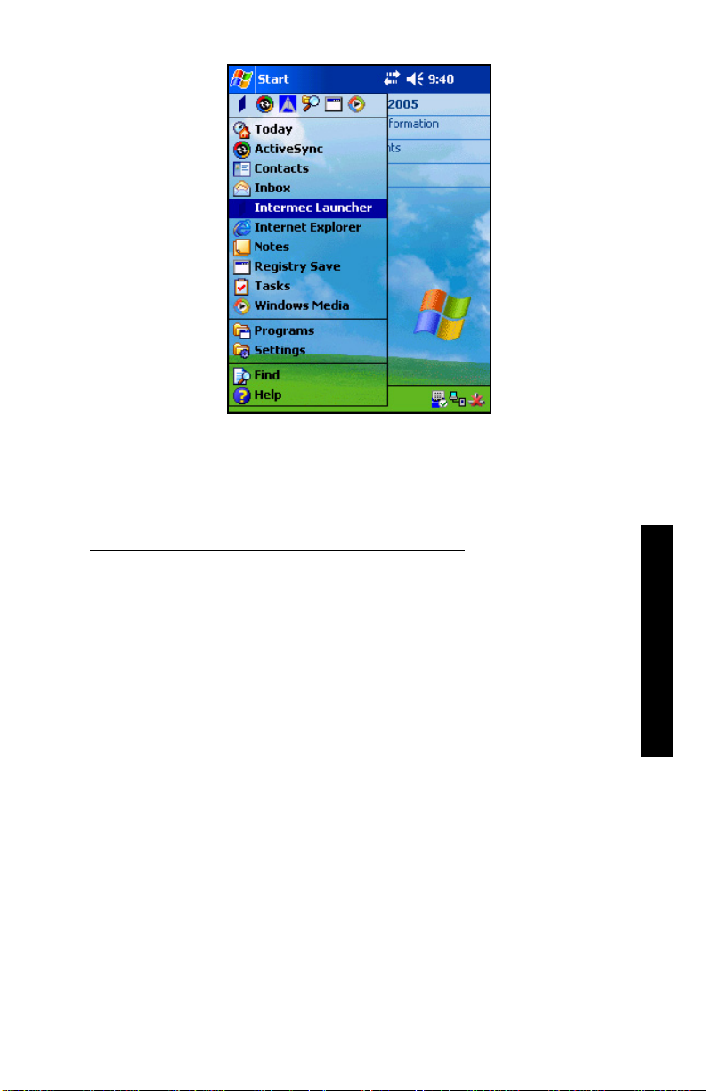
Figure 3–9. Return to Troxler Menu
PDA ACTIVESYNC CONFIGURATION
The Microsoft ActiveSync software provided on the Pocket PC
Companion CD allows the user create a partnership between the
PDA and a desktop computer using the serial cable provided with
the PDA. ActiveSync must be properly configured in order to use
the Data Manager software included with the gauge.
If the PDA becomes completely discharged, verify the ActiveSync
configuration after the unit is recharged.
To check the PDA’s ActiveSync settings:
Follow the directions on page 3–12 to display the Windows
desktop.
Press the Start button in the upper left corner of the desktop
and select ActiveSync from the dropdown menu.
3. GETTING STARTED
Model 3451 3–13
Page 48

Press the Tools button in the lower left corner of the
ActiveSync display and select Options… from the menu.
The ActiveSync PC Synchronization screen is displayed.
Press the Options… button. The ActiveSync PC
Synchronization Options screen is displayed.
Ensure that the Enable PC sync using this connection
checkbox is checked, and that 115200 Default is selected from
the dropdown menu. Also ensure that the Maintain
connection radio button is selected.
Press the ok button to return to the ActiveSync PC
Synchronization screen.
Press the ok button to the ActiveSync display.
Press the X button to return to the Windows desktop.
Follow the directions on page 3–12 to return to the Troxler
menu.
BLUETOOTH COMMUNICATION CONFIGURATION
The PDA is configured at the factory to enable Bluetooth
communications with the gauge. If communications between the
PDA and gauge cannot be established, check the Bluetooth
configuration as follows:
Follow the directions on page 3–12 to display the Windows
desktop.
Press the Start button in the upper left corner of the desktop
and select Settings from the dropdown menu.
Select the Connections tab at the bottom of the Settings
display.
Press the Bluetooth icon. A Bluetooth Settings window is
displayed with the Mode tab selected.
3–14
Page 49

Ensure that the On radio button is selected.
Select the File Transfer tab at the bottom of the display.
Ensure that the Enable radio button is selected.
Select the Wireless Printing tab at the bottom of the display.
Ensure that a gauge (3451-XXXX) is displayed in the lower
Connected box. If not:
Ensure that the gauge is turned on as described on page 3–8.
Press the Device Discovery button on the PDA. The PDA
will attempt to establish communications with (or discover)
the gauge. Upon discovery, the gauge will be listed in the
upper Devices box.
Highlight the 3451-XXXX listing in the Devices box and
press the Connect button. The 3451-XXXX listing should
move to the Connected box.
Highlight 3451-XXXX listing in the Connected box and press
the Properties button.
In the Choose COM Port box, ensure that the Com 6 radio
button is selected.
Ensure that the Enable Wireless Printing box is checked.
Press the ok button to return to the Bluetooth Settings
display.
Press the ok but
ton to return to the Settings display.
Press X to return to the Windows desktop.
Follow the directions on page 3–12 to return to the Troxler
menu.
3. GETTING STARTED
Model 3451 3–15
Page 50

ROADREADER PLUS MAIN MENU
NOTE
To ensure proper communications between the PDA and
gauge, always power the gauge on before starting the
RoadReader Plus software.
To start the RoadReader Plus software, press the Troxler 3451
button on the Troxler menu (see Figure 3–4 on page 3–10). The
software displays a splash screen that includes the software version
and gauge serial number. The software then establishes Bluetooth
wireless communications between the PDA and gauge.
When communications have been established, the software checks
the leak test interval and the date of the last leak test stored in the
PDA memory (see page 5–11). If the leak test interval has been
exceeded, the software displays Warning! Leak test is due. If
this warning appears, perform a leak test (see page A–13 and update
the leak test date (see page 5–13). Press the ok button to continue.
The software then checks the date of the last gauge calibration. If
the gauge is due for calibration, the software displays Warning!
Calibration is due. If this warning appears, Troxler recommends
returning the gauge and PDA to the nearest service center (refer to
page C–Error! Bookmark not defined.) for calibration. Press the
ok button to continue.
The software then communicates with the gauge to check the status
of the gauge battery. If the PDA cannot establish communications
with the gauge, the PDA displays Error! Checking Battery
Voltage. If this error message is displayed:
Check that the gauge is powered on.
Ensure that the gauge was powered on before the RoadReader
Plus software was started.
Ensure that the PDA is within 4.6 m (15 ft) of the gauge.
Verify the PDA’s Bluetooth communications configuration as
described on page 3–14.
Verify the PDA’s ActiveSync configuration as described on
page 3–13.
3–16
Page 51

Once the PDA establishes communications with the gauge, the
software displays the status of the gauge’s nickel-metal hydride
(NiMH) batteries, as shown in Figure 3–10. This display includes
the charger status (ON or OFF), the actual battery voltage, and the
battery status (OK or LOW). Press the Done button to continue.
NOTE
If the battery voltage falls below 5.5 V, the gauge shuts
off. Recharge the NiMH batteries as described on page
C–24.
The gauge then enters a five-minute warmup period, which allows
the baseboard electronics to warm up, and the gauge to acquire GPS
data.
NOTE
If the operator presses Abort to bypass the gauge
warmup, Troxler does not guarantee the accuracy of the
GPS location data.
NOTE
To preserve battery life, the gauge shuts down
automatically after five hours of inactivity.
3. GETTING STARTED
Figure 3–10. Battery Status Display
Model 3451 3–17
Page 52

When all of the checks performed at power on are complete, the
RoadReader Plus software displays the main menu shown in Figure
3–11). From this menu, the operator can take a reading or standard
count, change the gauge settings, or access a set of gauge tools.
The main menu also displays the measurement mode (Soil, Asphalt,
or Thin Layer), count time (15 seconds, 1 minute, or 4 minutes), and
the selected project name (if any).
Before taking measurements, read this manual carefully. If you do
not completely understand the sections that cover radiation safety,
contact your company radiation safety officer (RSO) or the nearest
Troxler representative.
NOTE
Pressing the Exit button on the main menu shuts down
the RoadReader Plus software and commands the gauge
to power off.
Figure 3–11. RoadReader Plus Software Main Menu
3–18
Page 53

PROJECT FILES
The Model 3451 stores measurement results in files called projects,
which are named by the operator. The Project function allows the
operator to create a new project, view project data, erase projects,
enable a project (make an existing project active so that additional
data may be added to it), or disable the active project.
NOTE
The gauge will not take a reading unless a project has
been created and is active.
To access the Project function, press Project Access on the
main menu (see Figure 3–11). The PDA displays the Project
Menu shown in Figure 3–12.
When checked, the Disable Storage to Gauge check box
prevents the PDA from storage measurement data to the gauge for
storage following a reading. The Disable Project Notes check
box disables the Would you like to add project notes? prompt
that otherwise is displayed following a measurement.
The following sections describe the other functions available from
the Project Menu.
NOTE
The Project function cannot be used to enter target
values, offsets, or special calibrations. For information
on entering target values, see page 5–14. For
information on using offsets and special calibrations,
refer to Chapter 6.
NEW PROJECT
To create a new project, press the New button on the Project
Menu shown in Figure 3–12. The PDA displays the first page of the
setup Wizard for a new project, as shown in Figure 3–13.
3. GETTING STARTED
Model 3451 3–19
Page 54

Figure 3–12. Project Menu
The Wizard is a series of screens that provides step-by-step
instructions for setting up a new project. Using the wizard, the
operator is prompted to:
Select the measurement mode (Soil, Asphalt, or Thin Layer).
For more information, refer to page 5–5.
Select the desired measurement units. For more information on
measurement units, refer to page 5–4.
Set the count time. For more information, see page 5–6.
For thin layer mode, enter the thickness of the top layer.
Enable any previously entered target values. For more
information on target values, see page 5–14.
The Wizard displays the operator selections for review. To change
a setting, press the Back button to return to the page for that
function or press the Cancel button to start over. When all
settings are correct, press the Next button to continue.
Figure 3–13. New Project
Setup Wizard, Page 1
3–20
Page 55

The Wizard displays an information screen, then requests a project
name. Enter a descriptive name for the project using the PDA’s
Block Recognizer, Keyboard, Letter Recognizer, or Transcriber
functions. For more information on these functions, refer to the
documentation provided with the PDA.
Press the Ok button when finished. The PDA displays the
confirmation message Gauge configuration has been set
according to your specifications. Press ok to continue.
VIEW PROJECT
The Model 3451 allows the operator to view measurement data
stored in any of the defined project files. To view project data, press
the View button on the Project Menu (see Figure 3–12). The
PDA displays the Project File Selector screen shown in Figure 3–14.
To select a project, press the project file name twice. The PDA
displays the measurement data stored in the project, as shown in
Figure 3–15. The data is stored sequentially, with the earliest
measurement listed first. To scroll through the data, press the scroll
bar using the stylus. If the selected project contains no measurement
data, the display will be blank. Press the Done button to return to
the Project Menu.
NOTE
The View Project function is intended to view
measurement data. To view setup information for the
active project, use the View Status function described on
page 3–25 and the View Setup function described on
page 5–3.
3. GETTING STARTED
Model 3451 3–21
Page 56

Figure 3–14. Project
File Selector
Figure 3–15. Project
Data Display
ERASE PROJECT
The Erase function enables the operator to delete a project file and
any data stored in it. To erase a project file, press the Erase
button on the Project Menu (see Figure 3–12). The PDA displays
the Project File Selector, as shown in Figure 3–14.
To select a project file, press the project file name twice. The PDA
displays the prompt shown in Figure 3–16.
Press OK to erase the project file. The PDA displays Project
file XXX has been erased. Press ok to continue.
If the erased project was not previous active, the PDA
returns to the Project Menu.
If the erased project was previously active, the PDA
displays Project XXX disabled! Press ok to return to
the Project Menu.
Press Cancel to exit without erasing the project file. The
PDA displays The project file named XXX will not be
erased! Press ok to return to the Project Menu.
3–22
Page 57

Figure 3–16. Project Erase Prompt
ENABLE PROJECT
To enable a project file, press the Enable button on the Project
Menu (see Figure 3–12). The PDA displays the Project File
Selector, as shown in Figure 3–14.
To select a project file, press the project file name twice. The PDA
displays The project XXX has been enabled. Press ok to
return to the Project Menu.
DISABLE PROJECT
To disable the currently active project file, press the Disable
button on the Project Menu (see Figure 3–12). The PDA displays
Do you wish to disable the currently active project, XXX?
Press Yes to disable the project. The PDA displays Project
XXX disabled! Press ok to return to the Project Menu.
Press No to return to the Project Menu without disabling the
project.
3. GETTING STARTED
Model 3451 3–23
Page 58

STATUS
The RoadReader Plus software enables the operator to view
information concerning the current gauge status, calibration
constants, temperature, battery status, and source decay. To access
these functions, press the Gauge Tools button on the main menu
(see Figure 3–11). The software displays the Gauge Tools menu
shown in Figure 3–17.
Press the Gauge Status button on the Gauge Tools menu to
access the Gauge Status Menu (see Figure 3–18).
NOTE
The PDA queries the gauge during the Gauge
Temperature and Battery Status functions. Therefore,
these functions can also be used to verify that the PDA
and gauge can communicate properly.
Figure 3–17. Gauge
Tools Menu
3–24
Figure 3–18. Gauge
Status Menu
Page 59

VIEW STATUS
The gauge status information includes the software version;
measurement units; count time; measurement mode; Marshall,
Proctor, and voidless density values; measurement mode status;
percent air voids status; specific gravity; and offset status and
values. To view this information, press the View Status button
on the Gauge Status Menu. The PDA displays a View Status
screen similar to the one shown in Figure 3–19. To scroll through
the various gauge values, press the scroll bar using the stylus. Press
the Done button to return to the Gauge Status Menu.
VIEW CONSTANTS
The constants include the calibration constants, as well as the date
of the most recent calibration. To view this information, press the
View Constants button on the Gauge Status Menu. The
PDA displays the View Constants screen shown in Figure 3–20.
To scroll through the calibration constant values, press the scroll bar
using the stylus. Press the Done button to return to the Gauge
Status Menu.
3. GETTING STARTED
Figure 3–19. View
Status Display
Figure 3–20. View
Constants Display
Model 3451 3–25
Page 60

GAUGE TEMPERATURE
To view the gauge temperature, press the Gauge Temperature
button on the Gauge Status Menu (see Figure 3–18). The PDA
displays the gauge temperature both in degrees Fahrenheit and in
degrees Celsius. Press the Done button to return to the Gauge
Status Menu.
BATTERY STATUS
To view the current status of the gauge’s NiMH batteries, press the
Battery Status button on the Gauge Status Menu (see Figure
3–18). The software displays the status of the batteries, as shown in
Figure 3–10 on page 3–17. This display includes the charger status
(ON or OFF), the actual battery voltage, and the battery status (OK
or LOW). Press the Done button to return to the Gauge Status
Menu.
NOTE
If the battery voltage falls below 5.5 V, the gauge shuts
off. Recharge the NiMH batteries as described on page
C–24.
3–26
Page 61

SOURCE DECAY
The strength of radioactive material is measured by its activity, or
rate of decay. This activity decreases with time. The length of time
it takes a given amount of radioactive material to decay to half of its
original strength is referred to as the half-life. The half-life of the
Am-241:Be source is 432 years. The half-life of the Cs-137 source
is 30 years.
The Source Decay Menu (see Figure 3–21) allows the operator
to view how the decrease in the radiation intensity of the source
affects standard counts. It displays the actual standard count, the
predicted standard count, and the difference between the two counts.
The gauge calculates the predicted standard count by adjusting the
calibration standard count for source decay.
To access the Source Decay Menu, press the Source Decay
button on the Gauge Status Menu (see Figure 3–18). Press the
Done button to return to the Gauge Status Menu.
3. GETTING STARTED
Figure 3–21. Source Decay Menu
Model 3451 3–27
Page 62

GPS LOCATION
To view the gauge’s current GPS location, press the GPS
Location button on the Gauge Status Menu (see Figure 3–18).
The PDA queries the gauge to take a GPS reading, and displays the
message Collecting GPS Data. Upon completion, the PDA
displays the gauge’s GPS location as shown in Figure 3–22. Press
OK to return to the Gauge Status Menu.
Figure 3–22. GPS Location Display
3–28
Page 63

CHAPTER 4
USING THE GAUGE
This chapter explains the basic use of the Troxler Model 3451
Enhanced RoadReader Plus. Basic use includes taking the daily
standard count, preparing measurement sites, setting the
measurement mode, and taking measurements.
CONTENTS
Taking a Standard Count .............................................................. 4–2
Take a New Standard Count................................................... 4–3
View Standard Counts............................................................ 4–6
Preparing a Test Site..................................................................... 4–7
Direct Transmission Mode..................................................... 4–7
Backscatter Mode................................................................... 4–9
Taking Measurements................................................................. 4–10
Soil Mode............................................................................. 4–11
Asphalt Mode....................................................................... 4–15
Thin Layer Mode.................................................................. 4–18
Model 3451 4–1
4. USING THE GAUGE
Page 64

TAKING A STANDARD COUNT
To adjust readings for source decay (see Appendix A) and natural
background radiation, take a daily standard count. A four-minute
daily standard count helps ensure the highest measurement
accuracy.
Locate the reference standard block shipped with the gauge. Always
take standard counts using the reference standard block.
Choose a standard count site. The standard count site should be:
Dry and flat
At least 3 meters (10 ft) from any large vertical surface
At least 10 meters (33 ft) from any other radioactive source
On asphalt, concrete, or compacted soil at least 10 centimeters
(4 in.) thick
Turn the gauge and PDA on as described on page 3–8. At the
RoadReader Plus main menu (see Figure 3–11 on page 3–18), press
the Standard Count button. The PDA displays the Standard
Menu (see Figure 4–1), which shows the last standard counts for
moisture (MS) and density (DS1 and DS2).
4–2
Figure 4–1. Standard Menu
Page 65

L
TAKE A NEW STANDARD COUNT
To take a new standard count, press the Take New Count
button. The PDA displays the prompt Place the gauge on the
standard block with the source rod in the STD position
and click OK.
Place the reference standard block on the standard count site. As
shown in Figure 4–2, place the gauge on the reference standard
block, with the right side (Troxler logo side) of the gauge against
the metal butt plate. Ensure that the source rod is in the standard
(SAFE) position and is firmly seated.
4. USING THE GAUGE
META
BUTT
REFERENCE STANDARD BLOCK
PLATE
Figure 4–2. Standard Count Position
Model 3451 4–3
Page 66

Press the OK button to begin the standard count. After taking the
standard count, the gauge software displays the results, as shown in
Figure 4–3.
Troxler recommends that the operator keep a daily log of the
standard counts (see Appendix E). To verify gauge stability,
compare the daily standard count to a reliable reference as follows:
During the first four days of operation of a new or recalibrated
gauge, compare the daily standard count to the factorycalibrated values.
After the first four days of operation (or after taking four
standard counts), compare the daily standard count to the
average of the last four counts. Acceptable standard count limits
are:
1% each day for DS1 (density standard),
1.3% each day for DS2 (density standard), and
2% each day for MS (moisture standard).
If the standard count passes, record the standard counts, then
press the Yes button. The PDA displays the prompt Do you
wish to erase the last four standard counts? Press
No. The PDA displays Standard counts have been
stored. Press the ok button to return to the Standard
Menu.
If the standard count fails by less than 10% and it has been more
than a month since the last standard count, then accept the
standard count by pressing the Yes button. At the Do you
wish to erase the last four standard counts? prompt,
press the Yes button. The PDA displays Standard counts
have been stored. Previous four standard counts were
erased from memory.
Press the ok button to return to the Standard Menu. Take
four additional standard counts. The last of these counts will be
compared to the previous four, and the standard counts should
pass. If not, repeat the procedure. If it still fails, perform a stat
test (see page C–2) and a drift test (see page C–5), then contact
your Troxler representative.
4–4
Page 67

Figure 4–3. Standard Count Results
If the standard count fails and it has been less than a month
since the last standard count, but the count was performed
correctly and the failure is less than 5%, press the Yes button.
If the failure is more than 5%, press the No button. Ensure
that the gauge is properly positioned on the reference standard
block (Figure 4–2). Verify that the standard count site meets the
criteria listed on page 4–2. Take another standard count and
accept it if it fails by less than 5%. If the standard count fails
four times, perform a stat test (see page C–2) and a drift test
(see page C–5), and then contact your Troxler representative.
After the standard count passes, the operator can take measurements
with the gauge. When not taking readings, always keep the source
rod in the SAFE position. For added operator safety, the source rod
automatically retracts to the SAFE position when the gauge is lifted
using the handle.
4. USING THE GAUGE
Model 3451 4–5
Page 68

VIEW STANDARD COUNTS
To view the last four standard counts, press the View Counts
button on the Standard Menu (see Figure 4–1). The PDA displays
the View Standard screen shown in Figure 4–4. Press the Done
button to return to the Standard Menu.
4–6
Figure 4–4. View Standard Screen
Page 69

PREPARING A TEST SITE
To ensure measurement accuracy, properly prepare the test site
before taking gauge measurements. This section describes how to
prepare test sites properly for direct transmission and backscatter
measurement modes. For a description of these measurement
modes, refer to page 2–2.
DIRECT TRANSMISSION MODE
Direct transmission mode is used on materials with layers four
inches thick or more. This mode is most commonly used on soils,
but can also be used to measure asphalt and concrete.
Locate a smooth site on the test material free from any large
holes, cracks, or debris.
If necessary, smooth the surface by moving the scraper plate in
a back and forth motion.
Fill any voids or depressions with fine sand. Strike off any
excess fill.
Place the scraper plate back on the surface and press down
slightly to level the surface.
Drill a hole in the test material as follows:
Put the drill rod through the extraction tool and then through
one of the guides on the scraper plate (Figure 4–5).
Wear safety glasses and a radiation dosimeter.
Place the drill rod assembly on the test site.
Step on the scraper plate.
Hammer the drill rod at least fifty millimeters (2 in.) deeper
than the desired test depth. The drill rod increments include
the additional depth.
Model 3451 4–7
4. USING THE GAUGE
Page 70

Figure 4–5. Drill Rod Assembly
Mark the test area before removing the scraper plate to ensure
the gauge is placed over the same area as the scraper plate
(Figure 4–6).
CAUTION
Under no circumstances should the source rod of the
gauge be used to drill holes.
MARK FOR SCRAPER
PLATE CENTER
4–8
SCRAPER
PLATE
METHOD 1
MARK FOR DRILL
ROD CENTER
Figure 4–6. Marking the Test Area
SCRAPER
PLATE
METHOD 2
EDGE
MARKS
Page 71

Remove the drill rod by pulling straight up and twisting the
extraction tool. Do not loosen the drill rod by tapping from side
to side with a hammer. Also, do not rock the extraction tool
from side to side. This will distort the hole or cause loose
material to fall into the hole.
Carefully pick up the scraper plate.
BACKSCATTER MODE
Backscatter mode is used on concrete, asphalt, and soil layers
approximately four inches thick.
Locate a smooth site on the test material.
Fill the voids on open mixes with sand or cement.
NOTE
The gauge base must rest on the test material, not the fill
material.
Ensure that the gauge does not rock. To ensure accurate
readings, the gauge base must be completely in contact with the
test material. If the gauge rocks, then find a more suitable test
site. If taking a measurement around a core, the gauge may be
moved a few inches away from the core to level it.
Model 3451 4–9
4. USING THE GAUGE
Page 72

TAKING MEASUREMENTS
NOTE
When not taking readings, always keep the source rod
in the SAFE (shielded) position. For added operator
safety, the source rod automatically retracts to the
SAFE position when the gauge is lifted by the handle.
If you do not hear a click when the gauge is raised to the SAFE
position, look at the bottom of the gauge to verify that the tungsten
sliding block is completely closed. If the gauge base opening is not
completely closed by the sliding block, the sliding block and fixed
tungsten block may require cleaning. Refer to page A–11 for
cleaning instructions.
WARNING
Do not store or transport the gauge unless the
sliding block is completely closed. Increased
radiation levels may cause excessive personnel
radiation exposure and may violate transportation
regulations.
The Gauge Status Menu (see page 3–24) allows the operator to
view the current gauge status. This feature provides a quick
overview of all enabled functions (mode of operation, enabled
offsets, displayed units, etc.). Check the gauge’s current status
before taking measurements. To change any of the gauge
parameters, refer to Chapter 5.
NOTE
Always take a standard count each day the gauge is to
be used (see page 4–2).
NOTE
A project must be enabled before taking a measurement.
Refer to page 3–19 for instructions on creating and
enabling projects.
4–10
Page 73

NOTE
During a measurement, if communications between the
PDA and gauge are interrupted, the PDA displays the
warning Please move closer to the gauge. Move the
PDA to within 1.5 m (5 ft) of the gauge and press ok.
SOIL MODE
To measure the moisture and density of soil, soil-stone aggregate,
and similar materials, follow the steps below:
Prepare the test site as described on page 4–7.
Place the gauge on the test area.
Insert the source rod into the hole made by the drill rod or
source rod adapter. Use care when inserting the source rod. Try
not to disturb the soil around the hole.
Lower the source rod to the measurement depth. Release the
trigger. Gently push down on the handle over the source rod to
lock the source rod into position. You should hear a click when
the source rod locks into position.
Gently slide the gauge to the right (towards the Troxler logo) so
the source rod makes contact with the wall of the hole.
Press the Take a Reading button on the RoadReader Plus
main menu (see Figure 3–11).
In the Manual depth mode (see page 5–10), the PDA
prompts for the source rod depth. Enter the source rod depth
and press the Ok button.
In the Automatic depth mode, the gauge software reads the
source rod depth strip to determine the source rod depth.
Note that the Proctor value is based on soil particles 3/8
inches or less in diameter (or those passing a #4 sieve). If an
unusual reading is obtained and oversize particles are
suspected, rotate the gauge 90. Use the same drill hole to
take a second reading.
4. USING THE GAUGE
Model 3451 4–11
Page 74

While the gauge is taking a measurement, the PDA displays the
time remaining.
After the count time, the gauge collects the count information
and GPS data, and then transmits this data to the PDA.
The PDA displays the prompt Would you like to add
project notes? This enables the operator to enter project
notes to be stored with the measurement results.
To continue without entering project notes, press No.
To add project notes, press Yes. The PDA displays the
Project Notes screen shown in Figure 4–7. Enter the
desired notes and press Ok. Troxler recommends that the
information entered as project notes does not exceed 40
characters.
The PDA displays the measurement results as shown in Figure
4–8. Note that the Fix Quality is displayed as GPS fix. This
indicates that the gauge’s GPS receiver was able to determine a
GPS location, but the Wide Area Augmentation System
(WAAS) was not available. For more information on GPS
accuracy, refer to page 1–5. Press the ok button to continue.
4–12
Figure 4–7. Entering Project Notes
Page 75

Figure 4–8. Count Results, Soil Mode
The PDA stores the measurement results in the active project,
then displays the confirmation message Soil results stored
in project: XXX, where XXX is the active project name. Press
the ok button to continue.
The PDA then stores the project data in the gauge. Upon
completion, the PDA displays Project storage to gauge
complete. Press the ok button to return to the main menu.
NOTE
If the gauge is unable to obtain GPS data after taking a
count, it will still send the count results to the PDA and
the results will be stored in the active project.
Lift the gauge from the test site by the source rod handle. This
returns the source rod to the SAFE (shielded) position. When
not taking readings, always keep the source rod in the SAFE
position. If you do not hear a click when the gauge is raised to
the SAFE position, look at the bottom of the gauge to verify
that the tungsten sliding block is completely closed. If the gauge
base opening is not completely closed by the sliding block, the
sliding block may require cleaning. Refer to page A–11 for
cleaning instructions.
4. USING THE GAUGE
Model 3451 4–13
Page 76

WARNING
Do not store or transport the gauge unless the
sliding block is completely closed. Increased
radiation levels may cause excessive personnel
radiation exposure and may violate transportation
regulations.
NOTE
To preserve battery life, the gauge shuts down
automatically after five hours of inactivity.
4–14
Page 77

ASPHALT MODE
To measure the density of asphalt, or hardened concrete of 4 inches
or more, follow the steps below:
Prepare the test site as described on page 4–9.
Place the gauge on the test area.
Lower the source rod to the backscatter position. Release the
trigger. Gently tap on the handle over the source rod to lock the
source rod into position. You should hear a click when the
source rod locks into position.
Press the Take a Reading button on the RoadReader Plus
main menu (see Figure 3–11).
In the Manual depth mode (see page 5–10), the PDA
prompts for the source rod depth. Enter the source rod depth
and press the Ok button.
In the Automatic depth mode, the gauge software reads the
depth strip on the source rod to determine the source rod
depth.
While the gauge is taking a measurement, the PDA displays the
time remaining.
After the count time, the gauge collects the count information
and GPS data, and then transmits this data to the PDA.
The PDA displays the prompt Would you like to add
project notes? This enables the operator to enter project
notes to be stored with the measurement results.
To continue without entering project notes, press No.
To add project notes, press Yes. The PDA displays a
Project Notes screen similar to the one shown in Figure
4–7 on page 4–12. Enter the desired notes and press Ok.
Troxler recommends that the information entered as project
notes does not exceed 40 characters.
Model 3451 4–15
4. USING THE GAUGE
Page 78

The PDA displays the measurement results as shown in Figure
4–9. Note that:
WetDensity
Voids
Note also that the Fix Quality is displayed as GPS fix. This
indicates that the gauge’s GPS receiver was able to determine a
GPS location, but the Wide Area Augmentation System
(WAAS) was not available. For more information on GPS
accuracy, refer to page 1–5. Press the ok button to continue.
The PDA stores the measurement results in the active project,
then displays the confirmation message Asphalt results
stored in project: XXX, where XXX is the active project
name. Press the ok button to continue.
The PDA then stores the project data in the gauge. Upon
completion, the PDA displays Project storage to gauge
complete. Press the ok button to return to the main menu.
Voidless
1001%
4–16
Figure 4–9. Count Results, Asphalt Mode
Page 79

NOTE
If the gauge is unable to obtain GPS data after taking a
count, it will still send the count results to the PDA and
the results will be stored in the active project.
Lift the gauge from the test site by the source rod handle. This
returns the source rod to the SAFE (shielded) position. When
not taking readings, always keep the source rod in the SAFE
position. If you do not hear a click when the gauge is raised to
the SAFE position, look at the bottom of the gauge to verify
that the tungsten sliding block is completely closed. If the gauge
base opening is not completely closed by the sliding block, the
sliding block may require cleaning. Refer to page A–11 for
cleaning instructions.
WARNING
Do not store or transport the gauge unless the
sliding block is completely closed. Increased
radiation levels may cause excessive personnel
radiation exposure and may violate transportation
regulations.
NOTE
To preserve battery life, the gauge shuts down
automatically after five hours of inactivity.
Model 3451 4–17
4. USING THE GAUGE
Page 80

THIN LAYER MODE
To measure the density of a top layer of asphalt, follow the steps
below. When taking counts after a core has been removed, Troxler
recommends averaging four one-minute readings taken around the
core site, as shown in Figure 4–10. If no core has been removed,
place the gauge over the test site, as shown in Figure 4–11.
Prepare the test site as described on page 4–9 for a backscatter
measurement.
Press the Take a Reading button on the RoadReader Plus
main menu (see Figure 3–11).
The PDA displays Position the gauge for count 1 out of
X and click OK, where X is the selected number of readings
per site.
Figure 4–10. Gauge Positioned Around a Core Site
(If Core Has Been Removed)
4–18
Page 81

Figure 4–11. Gauge Positioned Over Designated Test Site
Place the gauge on the test area and lower the source rod to the
backscatter position. Release the trigger. Gently tap down on the
handle over the source rod to lock the source into position. You
should hear a click when the source rod locks into position.
When the gauge is in position, press the OK button on the
PDA. While the gauge is taking a measurement, the PDA
displays the time remaining.
After the count time, the gauge collects the count information
and GPS data, and then transmits this data to the PDA.
The PDA displays the prompt Would you like to add
project notes? This enables the operator to enter project
notes to be stored with the measurement results.
To continue without entering project notes, press No.
To add project notes, press Yes. The PDA displays the
Project Notes screen shown in Figure 4–7 on page 4–12.
Enter the desired notes and press Ok. Troxler
recommends that the information entered as project notes
does not exceed 40 characters.
The PDA displays the results of the count (see Figure 4–12).
Note that the Fix Quality is displayed as GPS fix. This
indicates that the gauge’s GPS receiver was able to determine a
GPS location, but the Wide Area Augmentation System
(WAAS) was not available. For more information on GPS
accuracy, refer to page 1–5. Press the ok button to continue.
Model 3451 4–19
4. USING THE GAUGE
Page 82

Figure 4–12. Individual Count
Results, Thin Layer Mode
Reposition the gauge as prompted by the PDA and repeat the
above procedure at each position.
After the final count is completed, the gauge collects the count
information and GPS data, and then transmits this data to the
PDA.
The PDA displays the averaged measurement results as shown
in Figure 4–13. Press the ok button to continue.
If the gauge is unable to obtain GPS data after taking a
count, it will still send the count results to the PDA and
the results will be stored in the active project.
Figure 4–13. Averaged Count
Results, Thin Layer Mode
NOTE
4–20
Page 83

The PDA stores the measurement results in the active project,
then displays the confirmation message Thin lift results
stored in project: XXX, where XXX is the active project
name. Press the ok button to continue.
The PDA then stores the project data in the gauge. Upon
completion, the PDA displays Project storage to gauge
complete. Press the ok button to return to the main menu.
Lift the gauge from the test site by the source rod handle. This
returns the source rod to the SAFE (shielded) position. When
not taking readings, always keep the source rod in the SAFE
position. If you do not hear a click when the gauge is raised to
the SAFE position, look at the bottom of the gauge to verify
that the tungsten sliding block is completely closed. If the gauge
base opening is not completely closed by the sliding block, the
sliding block may require cleaning. Refer to page A–11 for
cleaning instructions.
WARNING
Do not store or transport the gauge unless the
sliding block is completely closed. Increased
radiation levels may cause excessive personnel
radiation exposure and may violate transportation
regulations.
NOTE
To preserve battery life, the gauge shuts down
automatically after five hours of inactivity.
Model 3451 4–21
4. USING THE GAUGE
Page 84

NOTES
4–22
Page 85

CHAPTER 5
SETUP AND TARGET MENUS
The RoadReader Plus software includes a Gauge Setup menu,
which allows the operator to manually set or change operating
parameters usually configured when setting up a project file. This
chapter describes these parameters, as well as the use of target
values.
CONTENTS
Gauge Setup Menu ....................................................................... 5–2
View Setup............................................................................. 5–3
Units....................................................................................... 5–4
Mode ...................................................................................... 5–5
Count Time............................................................................. 5–6
Customer Name...................................................................... 5–7
User Code............................................................................... 5–9
Depth Strip........................................................................... 5–10
Leak Test.............................................................................. 5–11
Target.......................................................................................... 5–14
Enter a Target Value ............................................................ 5–16
View a Target Value ............................................................ 5–17
Erase a Target Value............................................................ 5–17
Enable a Target Value.......................................................... 5–18
Disable the Target Value...................................................... 5–18
5. SETUP & TARGET MENUS
Model 3451 5–1
Page 86

GAUGE SETUP MENU
The Model 3451 software groups all the setup features in the
Gauge Setup menu. To access the Gauge Setup menu, press
the Gauge Settings button on the main menu (see Figure 3–11
on page 3–18). The PDA displays the Change Settings menu
shown in Figure 5–1. Press the Gauge Setup button to display
the Gauge Setup menu shown in Figure 5–2.
To select a menu option, press the button that corresponds to the
option. Press the Done button to return to the main menu. The
following sections describe the setup options.
NOTE
Most of the setup options described in the following
sections are configured by the setup wizard during the
creation of a new project (see page 3–19). If the operator
later changes any of the gauge settings using the Gauge
Setup menu, those changes will be saved in the active
project file.
Figure 5–1. Change
Settings Menu
5–2
Figure 5–2. Gauge
Setup Menu
Page 87

VIEW SETUP
To view the current gauge setup, press the View Setup button.
The PDA displays the View Setup screen (see Figure 5–3), which
shows the software version, gauge serial number, source rod type,
charger and battery status, count time, measurement units,
measurement mode, and depth mode. To scroll through the display,
press the scroll bar using the stylus. Press the Done button to
return to the Gauge Setup menu.
5. SETUP & TARGET MENUS
Figure 5–3. View Setup Display
Model 3451 5–3
Page 88

UNITS
The Model 3451 can display measurement results in either metric
(SI) or U.S. units. To set the units, press the Units button on the
Gauge Setup menu shown on page 5–2. The PDA displays the
Set Units Menu shown in Figure 5–4.
The current units selection is shown at the top of the menu. To
select new measurement units, press the corresponding button. The
PDA sets the new units and displays a confirmation message. Press
the ok button to return to the Set Units Menu.
Press the Done button to return to the Gauge Setup menu.
5–4
Figure 5–4. Set Units Menu
Page 89

MODE
The Model 3451 provides three measurement modes (Soil, Asphalt,
and Thin Layer) for precise readings on base and thin layer asphalt,
concrete, soil, soil-stone aggregate, and similar materials.
Use the Soil mode when measuring soil or a soil-stone
aggregate.
Use Asphalt mode when measuring concrete or asphalt layers of
4 inches or greater.
Select the Thin Layer mode when measuring thin-layer asphalt
of less than 4 inches. In thin layer mode, the gauge can average
up to 20 readings from a single test location. When using this
function, the PDA automatically prompts for repositioning of
the gauge from a test location and begins another measurement.
After all measurements have been completed, the gauge
calculates the average density of the test material. When taking
counts on thin layer asphalt, Troxler recommends averaging
four one-minute readings.
NOTE
The Model 3451 gauge can store measurements
performed using different modes under a single project
name. For example, the operator may select the Soil
mode when setting up the project (see page 3–19), but
can also save Asphalt mode measurements under the
same project.
To change the measurement mode for the current project, press the
Mode button on the Gauge Setup menu shown on page 5–2.
The PDA displays the message shown in Figure 5–5.
5. SETUP & TARGET MENUS
To maintain the current measurement mode, press Cancel.
To change measurement modes, press OK. The PDA displays
the setup Wizard (see page 3–20). Follow the prompts in the
wizard to select the mode, measurement units, count time, and
so on. Upon completion, the wizard requests a project name
while displaying the currently named project file. To change the
project name, enter a new one, or press ok to accept the
current name.
Model 3451 5–5
Page 90

Figure 5–5. Mode Change Display
COUNT TIME
The count time defines how long the gauge reads. Longer count
times produce better measurement precision. Troxler recommends a
count time of one minute for most sample measurements.
To change the count time, press the Time button on the Gauge
Setup menu (see page 5–2). The PDA displays the Count Time
Menu shown in Figure 5–6. The current count time is displayed at
the top of the menu.
To select the desired count time, press the corresponding button.
The PDA sets the count time and displays a confirmation message.
Press the ok button to return to the Count Time Menu.
Press the Done button to return to the Gauge Setup menu
5–6
Page 91

Figure 5–6. Count Time Menu
CUSTOMER NAME
The Model 3451 can store a customer name or other messages up to
20 characters. To enter a customer name, press the Name button
on the Gauge Setup menu (see page 5–2).
As shown in Figure 5–7, the Customer Name option requires an
access code. The initial access code is shown on page xv. For
instructions on changing the user code, see page 5–9.
To enter the access code, use the PDA’s Block Recognizer,
Keyboard, Letter Recognizer, or Transcriber functions. For more
information on these functions, refer to the documentation provided
with the PDA.
After the correct access code is entered, press the Done button.
The PDA displays the question Do you want to change name?
Press the OK button to continue to the Enter Customer Name
Menu shown in Figure 5–8.
5. SETUP & TARGET MENUS
Model 3451 5–7
Page 92

Figure 5–7. Enter Code Menu
The customer name currently stored in the gauge memory is
displayed. To change the name, use the PDA’s Block Recognizer,
Keyboard, Letter Recognizer, or Transcriber functions. For more
information on these functions, refer to the documentation provided
with the PDA.
Enter the new name and press the Done button. The PDA stores
the new customer name and returns to the Gauge Setup menu.
Figure 5–8. Enter
Customer Name Menu
5–8
Page 93

USER CODE
The User Code function enables the operator to change the code
used to access certain gauge functions. The code can be any numeric
value from 1 to 9999. When shipped, the access (user) code is set to
the value shown on page xv.
To change the code, press the User Code button on the Gauge
Setup menu. The PDA requests the current user code, as shown in
Figure 5–7 on page 5–8. Enter the access code using the PDA’s
Block Recognizer, Keyboard, Letter Recognizer, or Transcriber
functions, and press the Done button. (For more information on
these functions, refer to the documentation provided with the PDA.)
The PDA displays the Change User Code Menu shown in
Figure 5–8. Enter the new code and press the Done button. The
PDA displays a confirmation message showing the entered code and
the question Is this correct? Press the OK button to accept the
new code and return to the Gauge Setup menu, or the Cancel
button to return to the Change User Code Menu.
5. SETUP & TARGET MENUS
Figure 5–9. Change User Code Menu
Model 3451 5–9
Page 94

DEPTH STRIP
The Depth Strip feature allows the operator to set the depth mode.
The depth mode determines how the gauge will receive data about
the source rod depth. The Model 3451 offers two depth modes:
Automatic and Manual. In the Automatic mode, the gauge software
reads a depth strip on the index rod to determine the source rod
depth. In the Manual mode, the operator enters the source rod depth
at a gauge prompt whenever taking a measurement.
NOTE
In the Manual mode, the gauge uses the source rod
depth entered by the operator. If the operator enters an
incorrect depth, the measurement results will be invalid.
To access the Depth Indicator Menu (see Figure 5–10), press the
Depth Strip button on the Gauge Setup menu (see page 5–2).
To select a depth mode, press either the Automatic or Manual
button. The PDA sets the mode and displays a confirmation
message. Press ok to return to the Depth Indicator Menu.
Press the Done button to return to the Gauge Setup menu.
5–10
Figure 5–10. Depth Indicator Menu
Page 95

LEAK TEST
To ensure the integrity of the radioactive source encapsulation, the
Model 3451 must be periodically leak tested. For instructions on
performing the leak test, see page A–13.
The gauge uses the leak test interval and leak test date values to
determine when a leak test is due. To change these values, press the
Leak Test button on the Gauge Setup menu (see page 5–2).
The PDA displays the Leak Test Menu shown in Figure 5–11.
NOTE
The Leak Test function does not replace the leak test
analysis records that must be maintained for review by
your licensing agency.
5. SETUP & TARGET MENUS
Figure 5–11. Leak Test Menu
Model 3451 5–11
Page 96

Leak Test Interval
By default, the leak test interval is set to six months (183 days). In
countries outside of the United States, the time required between
leak tests may vary from six months to three years. Check local
regulations, and then refer to the following instructions on setting
the leak test interval.
To change the leak test interval, press the Leak Test Interval
button. The PDA displays the Leak Test Interval Menu shown in
Figure 5–12.
The current leak test interval is displayed at the top of the menu.
Press the Abort button to return to the Leak Test Menu without
changing the value. To change the leak test interval, enter the
desired number of days using the PDA’s Block Recognizer,
Keyboard, Letter Recognizer, or Transcriber functions. (For more
information on these functions, refer to the documentation provided
with the PDA.) Press the Done button. The PDA sets the new
value and returns to the Leak Test Menu.
5–12
Figure 5–12. Leak Test Interval Menu
Page 97

Leak Test Date
The Leak Test Date function allows the operator to view or change
the date of the last leak test. The gauge alerts the operator if the leak
test interval has been exceeded. To view or change the leak test
date, press the Leak Test Date button. The PDA displays the
Leak Test Date Menu shown in Figure 5–13.
The current leak test date is displayed at the top of the menu. Press
the Abort button to return to the Leak Test Menu without
changing the value. To change the leak test date, enter the desired
date using the PDA’s Block Recognizer, Keyboard, Letter
Recognizer, or Transcriber functions. (For more information on
these functions, refer to the documentation provided with the PDA.)
Press the Done button. The PDA sets the new value and returns to
the Leak Test Menu.
NOTE
The month and day must each be entered as two-digit
numerals, with leading zeroes as required. The year
must be entered as a four-digit numeral. For example, to
set the leak test date to April 8, 2005, enter 04/08/2005.
5. SETUP & TARGET MENUS
Figure 5–13. Leak Test Date Menu
Model 3451 5–13
Page 98

TARGET
Target values include Proctor, percent air voids, Marshall, and
voidless density values.
The gauge uses the Proctor value to calculate the compaction level
when taking counts in the Soil mode. The gauge uses the specific
gravity of the material to calculate percent air voids and void ratio.
The gauge uses a default value of 2.7, which may not be appropriate
for all soil types. If the true percent air voids is desired, a specific
gravity for the soil being measured must be entered.
The gauge uses the Marshall and/or voidless density values to
calculate the compaction level in the Asphalt and Thin Layer modes.
The voidless density is the maximum theoretical density for the test
material as obtained in laboratory tests.
The gauge uses the target values to determine the percent
compaction after it has determined the density of the test material.
The Target function enables the operator to enter and store a new
target value, as well as to view, erase, enable, or disable a stored
value. To access this function, press the Target button on the
main menu (see Figure 3–11). Depending on the current
measurement mode (Soil, Asphalt, or Thin Layer), the PDA displays
one of the two menus shown in Figure 5–14.
In Soil mode, the Target Menu is used to enter, view, erase,
enable, or disable Proctor and percent air void values. In the Asphalt
and Thin Layer modes, the Target Menu is used to manage the
Marshall and voidless density values. To manage a target value,
press the corresponding button on the Target Menu. The PDA
displays a menu similar to the one shown in Figure 5–15.
NOTE
Because the menus for managing the Proctor, percent
air voids, Marshall, and voidless density values are
essentially the same, the following sections describe only
the Proctor Value Menu.
5–14
Page 99

5. SETUP & TARGET MENUS
Soil Mode
Asphalt or Thin Layer Mode
Figure 5–14. Target Menus
Figure 5–15. Proctor Value Menu
Model 3451 5–15
Page 100

ENTER A TARGET VALUE
To enter a new target value, press the New button on the Proctor
Value Menu (see Figure 5–15). As shown in Figure 5–16, the PDA
displays its onscreen keyboard and requests the new value. Enter the
target value using the selected measurement units (see page 5–4),
then press the Ok button.
The PDA then requests a descriptive name for the target value.
Enter an alphanumeric name (up to 20 characters) for the target
value and press the Ok button. The name should be as descriptive
as possible, to ensure that the target value can be easily identified.
The PDA stores the new value and asks if the new value is to be
activated. To activate the new value, press the Yes button.
Pressing the No button allows the operator to store the value for
later use. The PDA returns to the Proctor Value Menu.
5–16
Figure 5–16. Input Proctor Value Display
 Loading...