

Page 1
OFFSET FUNCTION
The gauge can be adjusted using an offset. The gauge applies
the offset to measurements until the offset is disabled or the
gauge is turned off.
Press 〈OFFSET〉. The gauge displays the Offset menu.
WET DENSITY OFFSET
To select wet density offset from the Offset menu, press 〈1〉. If
the function is disabled, enable it by pressing 〈YES〉. To
change the current factor, press 〈YES〉. To enter a new wet
density offset, select either + (positive) or – (negative) to
display:
-WD Offset-
Press Enter
when completed
Enter the new factor and press 〈ENTER〉.
MOISTURE OFFSET
To select moisture offset from the Offset menu, press 〈2〉. After
selection, enable the function by pressing 〈YES〉.
When prompted Do you want a new M–Offset?, press
〈YES〉. For a gauge-derived offset, value 〈1〉. For a stored
value, press 〈2〉.
For more information on offsets, see the Model 3440
Manual of Operation and Instruction.
TESTING AND MEASUREMENT
Ensure that the gauge is in the correct mode. Press 〈SHIFT〉
and 〈MODE〉.
For Soils mode, press 〈1〉. For Asphalt mode, press 〈2〉.
Ensure that the count time is correct.
Ensure that the depth is set properly. If not, see if the Depth
function is set to Automatic. To check the mode, press 〈SHIFT〉
then 〈DEPTH〉.
When the gauge is in the correct position, press 〈START〉 to
begin the test.
SOIL AND BASE COURSES
After the measurement is complete, the gauge displays:
%PR = xxxx%
DD = xxxx
WD = xxxx
M = xxx% M = xxx
To store the reading, press 〈STORE〉 (see Storage Function).
ASPHALT SURFACE
After the measurement is complete, the gauge displays:
%MA = xxxx
WD = xxxx
M= xxxx %M= xxxx
%VOIDS = xxxx
To store the reading, press 〈STORE〉 (see Storage Function).
STORAGE FUNCTION
When storing a reading, the gauge can also prompt the operator
for information required on U.S. Federal Highway
Administration (FHWA) projects. To select this option, select
Special Rdwy from the Special functions menu. The gauge
displays the current storage status. Press 〈YES〉 to toggle the
function ON or OFF. To accept the displayed status, press
〈NO/CE〉.
Assign a project number before storing readings by pressing
〈SHIFT〉 and 〈PROJECT〉. If the displayed project number is
correct, press 〈NO〉. If the project number is incorrect, press
〈YES〉 and enter a new project number (up to 12 characters).
To store readings, press 〈STORE〉. Follow the gauge prompts
to enter any additional project information.
Model 3440
Surface Moisture-Density Gauge
QUICK
REFERENCE
CARD
Troxler Electronic Laboratories, Inc.
3008 Cornwallis Road
P.O. Box 12057
Research Triangle Park, NC 27709
Tel (919) 549-8661 Fax (919) 549-0761
PN 104337
October 1999
Edition 1.1
Page 2
GAUGE START UP
NOTE
The operator should wear a dosimeter or radiation
badge when working with the 3450 Surface MoistureDensity Gauge.
Press 〈ON〉. The display will come on and the gauge performs a
short self-test routine. Following the self-test, the gauge
displays:
READY mm/dd/yyyy
Depth: XXXX
Time: XXXXXX
Batt volts: XX
While displaying the count time, depth, and remaining battery
life, the screen alternates between displaying the current time
and date.
GAUGE SET UP
TIME FUNCTION
To view the current time for test measurements, press 〈TIME〉.
Make the desired time selection with the numeric keys and
press 〈ENTER〉.
CHANGING THE DATE AND TIME
To access the current date and time settings, press 〈SHIFT〉
then 〈SPECIAL〉. Press 〈1〉, 〈9〉, and 〈ENTER〉. Enter the
access code and press 〈ENTER〉. To select the Time/Date
function, press 〈1〉.
Current Date:
mm/dd/yyyy
Do you want to
change Date?
To change the date and time, press 〈YES〉. Both the date and
time must include leading zeros. For example, September 5,
1999 must be entered as 09051999 and 9:05 must be entered as
0905. Enter the new date and, when prompted, the new time.
CHANGING MARSHALL/PROCTOR/VOIDLESS VALUES
To select or change a Marshall, Proctor, or voidless density
value, press 〈PROCTOR/MARSHALL〉. At the Want to
change? display, press 〈YES〉. At the next display, use the
numeric keys to select the type of value you are using.
Marshall or Proctor Value
If changing either a Marshall or Proctor value, the gauge
prompts for either a Stored value (press 〈1〉) or a New value
(press 〈2〉).
If enabling a stored value, the gauge displays the values. Press
the numeric key that corresponds to the desired value.
For a new value, use the numeric keys number keys to enter the
new value, then press 〈ENTER〉. At the Do you want to
save this value for later use? prompt, press 〈YES〉. As
when enabling a stored value, select the desired value.
Density Value
Enter the voidless density value and press 〈ENTER〉.
THE STANDARD COUNT
To check the gauge operation and allow the gauge to
compensate for natural source decay, take a standard count
daily. Use the reference standard block for this operation.
Place the reference standard block on a dry, flat surface of
asphalt or compacted soil with a density of at least 100 pcf
(1600 kg/m
any building or vertical structure and 10 m (33 ft) from any
other nuclear gauge or radioactive source.
Ensure that the top surface of the reference standard block and
bottom of the gauge are clean of debris. Place the gauge
between the grooves on the reference standard block with the
source rod to the left and the right side of the gauge against the
metal butt plate on the block.
For the first display, press 〈STANDARD〉. For the second
display, press 〈YES〉.
-Standard Count Is gauge on Ref.
block & Source
rod in SAFE pos?
To begin the count, press 〈YES〉. Upon completion of the
count, the gauge will “beep.” Write the count in the standard
count log and accept the count by pressing 〈YES〉. When in the
Ready mode, the gauge is ready to take test measurements.
3
). The location should be at least 2 m (6 ft) from
-Standard Count DS=xxxx
MS=xxxx
Take new count?
SITE PREPARATION
Surface preparations are critical to gauge performance and test
result accuracy. The following procedures will help ensure
accurate test results.
SOIL AND BASE COURSES
CAUTION
Safety glasses must be worn during this procedure.
Place the scraper plate on the test surface. Smooth the area by
sliding the plate back and forth. Lift the plate from the surface
and fill any voids or
depressions. Replace the plate
and press down slightly to
further level the surface.
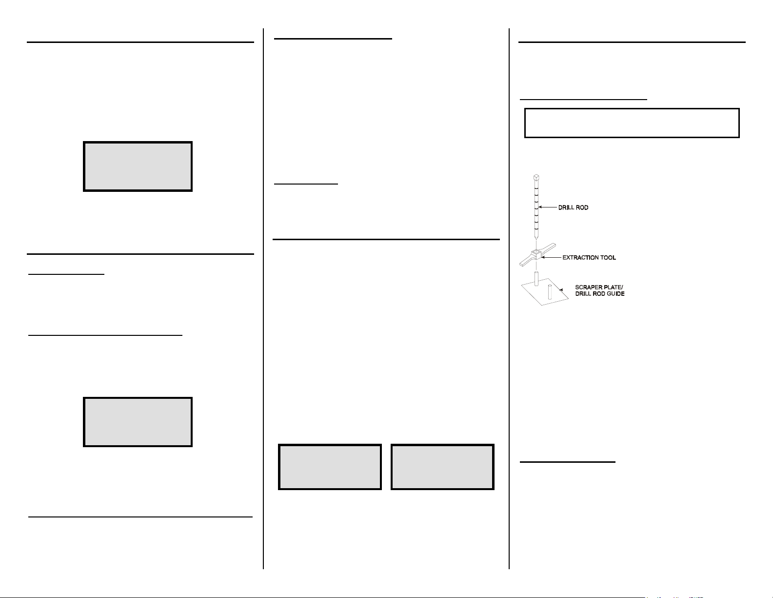
Put the drill rod through the
extraction tool then through
one of the guides on the
scraper plate (see figure).
Wearing safety glasses, step
on the scraper plate and
hammer the drill rod at least
50 millimeters (2 in) deeper
than the desired test depth.
The drill rod increment
markings include the additional depth. Mark the test area.
Remove the drill rod by pulling straight up on the drill rod
extraction tool. Do not loosen the drill rod by moving it from
side-to-side.
To ensure no debris falls into the hole, remove the scraper plate
by lifting it straight up.
Place the gauge on the smoothed surface and ensure the source
rod is over the drilled hole. Lower the source rod to the correct
depth and release the trigger. Gently slide the gauge to the
right, so the source rod touches the side of the hole.
ASPHALT SURFACE
Locate a smooth, level site on the asphalt. Fill the voids on
open mixes with sand or cement. The gauge base must rest on
the asphalt, not the fill material! Ensure that the gauge does
not "rock." It must remain level and steady. If the gauge rocks,
then find a more suitable test site.
Place the source rod in the backscatter position (lower the
source rod one notch) and release the trigger. Ensure that the
source rod is in the proper index rod notch and not resting
on the asphalt.
 Loading...