

Page 1

Manual of Operation and Instruction
Model 3430 Plus & 3440 Plus
Surface Moisture-Density Gauge
Troxler Electronic Laboratories, Inc.
3008 Cornwallis Rd. • P.O. Box 12057
Research Triangle Park, NC 27709
Phone: 1.877.TROXLER
Outside the USA: +1.919.549.8661
Fax: +1.919.549.0761
www.troxlerlabs.com
Page 2

Troxler gauges are protected by U.S. and foreign patents
Copyright © 2007
Troxler Electronic Laboratories, Inc.
All Rights Reserved
No part of this manual may be reproduced or transmitted in any
form or by any means, electronic or mechanical, including
photocopying, recording, or information storage and retrieval
systems, for any purpose without the express written permission of
Troxler Electronic Laboratories, Inc.
Fantastic is a trademark of Dow Consumer Products, Inc.
Federal Express is a registered trademark of the Federal Express
Corporation.
409 is a trademark of the Clorox Company.
Magnalube-G is a registered trademark of Carleton-Stuart
Corporation.
Microsoft, Excel, HyperTerminal, Windows, and Word are
registered trademarks of Microsoft Corporation.
WD-40 is a registered trademark of the WD-40 Company.
PN 110890
February 2007
Edition 1.0
ii
Page 3

TROXLER SERVICE CENTERS
Troxler Corporate Headquarters
3008 Cornwallis Road
P.O. Box 12057
Research Triangle Park, NC 27709
Phone: 1.877.TROXLER (1.877.876.9537)
Outside the U.S.A.: +1.919.549.8661
Fax: +1.919.549.0761
Web: www.troxlerlabs.com
Technical Support
Phone: 1.877.TROXLER (1.877.876.9537)
E-mail: TroxTechSupport@troxlerlabs.com
Midwestern Branch Office
1430 Brook Drive
Downers Grove, IL 60515
Fax: 630.261.9341
Western Regional Branch Office
11300 Sanders Drive, Suite 7
Rancho Cordova, CA 95742
Fax: 916.631.0541
Southwestern Branch Office
2016 East Randol Mill Road
Suite 406
Arlington, TX 76011
Fax: 817.275.8562
To locate an independent, Troxler-authorized service
center near you, call 1.877.TROXLER (1.877.876.9537).
Florida Service Center
2376 Forsyth Road
Orlando, FL 32807
Fax: 407.681.3188
Troxler European Subsidiary
Troxler Electronics GmbH
Gilchinger Strasse 33
D.82239 Alling nr. Munich, Germany
Phone: ++49.8141.71063
Fax: ++49.8141.80731
E-mail: troxler@t-online.de
NOTE
Model 3430 Plus & 3440 Plus iii
Page 4

HOW TO USE THIS MANUAL
Congratulations on the purchase of a Troxler Model 3430 Plus or
3440 Plus Surface Moisture-Density Gauge. Troxler continues the
proven technology of its 3400 Series surface moisture-density
gauges with the Troxler Model 3430 Plus and 3440 Plus.
The Model 3430 Plus & 3440 Plus Manual of Operation and
Instruction contains information on safely using this gauge. Also
included in this manual are safety warnings, gauge setup,
troubleshooting, and general maintenance.
NOTE
Before operating the gauge, read this manual carefully.
If you do not completely understand the sections that
cover radiation safety, contact your company radiation
safety officer (RSO) or the nearest Troxler
representative.
iv
Page 5
CONVENTIONS USED IN THIS MANUAL
Throughout this manual, symbols and special formatting are used to
reveal the purpose of the text as follows:
WARNING
Indicates conditions or procedures that, if not
followed correctly, may cause personal injury.
CAUTION
Indicates conditions or procedures that, if not followed
correctly, may cause equipment damage.
NOTE
Indicates important information that must be read to
ensure proper operation.
〈KEY〉 Angle brackets and a different typestyle indicate a
key or character (number or letter) to press on the
gauge keypad. For example, “Press 〈START〉”
means to press the key labeled START.
DISPLAY A different typestyle is used in text to indicate
information or messages displayed on the gauge.
DISPLAY - Typestyle
and shading used to
simulate the gauge
display
♦ Diamonds indicate a list of things needed (such as
equipment) or things to know.
Check marks indicate the performance of an action.
With lists of check marks, follow the instructions in
the order of the check marks.
Triangles indicate that more than one option is
available. Carefully select the option that applies.
Model 3430 Plus & 3440 Plus v
Page 6

NOTES
vi
Page 7

TABLE OF CONTENTS
CHAPTER 1. INTRODUCTION
Introduction................................................................................... 1–2
Gauge Parts and Accessories........................................................1–5
Unpacking and Inspection ............................................................ 1–7
CHAPTER 2. THEORY OF OPERATION
Density..........................................................................................2–2
Moisture........................................................................................ 2–3
Calibration .................................................................................... 2–5
CHAPTER 3. GETTING STARTED
Gauge Illustration ......................................................................... 3–2
Control Panel................................................................................ 3–3
Source Rod Positions.................................................................... 3–5
Daily Inspection............................................................................ 3–6
Turning the Gauge On .................................................................. 3–7
Setup............................................................................................. 3–9
CHAPTER 4. USING THE GAUGE
Taking a Standard Count .............................................................. 4–2
Preparing a Test Site..................................................................... 4–7
Taking Measurements................................................................. 4–10
Recall.......................................................................................... 4–17
CHAPTER 5. SETUP MENU
Setup Menu................................................................................... 5–3
Count Time................................................................................... 5–4
Set Units........................................................................................ 5–4
Depth Mode.................................................................................. 5–4
Stat Test........................................................................................ 5–5
Drift Test....................................................................................... 5–7
Nomograph................................................................................. 5–10
Precision ..................................................................................... 5–15
Options........................................................................................ 5–17
Battery Status.............................................................................. 5–18
Percent Air Voids (Soil Mode)................................................... 5–19
Model 3430 Plus & 3440 Plus vii
Page 8

TABLE OF CONTENTS (Continued)
CHAPTER 6. TARGET MENU
Target Menu..................................................................................6–2
Target Values ................................................................................ 6–3
CHAPTER 7. CALIBRATION OFFSETS
Offset Menu...................................................................................7–2
Density Offset................................................................................ 7–3
Moisture Offset..............................................................................7–4
Trench Offset.................................................................................7–8
CHAPTER 8. PROJECT DATA
Project Menu .................................................................................8–2
Select.............................................................................................8–3
View ..............................................................................................8–4
Create a Project ............................................................................. 8–5
Erase Projects................................................................................8–6
Output Project................................................................................8–7
Set Output Destination ................................................................8–10
Deactivate....................................................................................8–11
Auto-Store................................................................................... 8–12
Manual Store ...............................................................................8–14
CHAPTER 9. EXTENDED MENU
Extended Menu..............................................................................9–2
Clock/Calendar..............................................................................9–3
User ID..........................................................................................9–3
Customer Name.............................................................................9–3
Language....................................................................................... 9–4
Source Decay.................................................................................9–5
Erase Standard Counts...................................................................9–6
Low Battery Warning....................................................................9–7
Software Reset...............................................................................9–8
Test Menu......................................................................................9–9
APPENDIX A. RADIATION THEORY AND SAFETY
Radiation Theory..........................................................................A–2
Radiation Safety...........................................................................A–5
Regulatory Requirements...........................................................A–14
Gauge Use Precautions...............................................................A–17
Radiation Profile.........................................................................A–18
viii
Page 9

TABLE OF CONTENTS (Continued)
APPENDIX B. TRANSPORTATION AND SHIPPING
U.S. Shipping Requirements.........................................................B–2
Canadian Shipping Requirements.................................................B–4
APPENDIX C. TROUBLESHOOTING AND SERVICE
Troubleshooting............................................................................C–2
Display Contrast ...........................................................................C–9
Batteries......................................................................................C–10
Mechanical Maintenance............................................................C–15
Replacement Parts ......................................................................C–18
Returning the Gauge for Service ................................................C–30
APPENDIX D. STANDARD COUNT LOG
APPENDIX E. UNIT CONVERSION
Measurement Units.......................................................................E–2
Radiological Units ........................................................................E–2
APPENDIX F. GAUGE SPECIFICATIONS
Measurement Specifications......................................................... F–2
Radiological Specifications .......................................................... F–4
Electrical Specifications ...............................................................F–5
Mechanical Specifications............................................................F–7
APPENDIX G. SPECIAL EUROPEAN CONSIDERATIONS
Declaration of Conformity........................................................... G–2
Safety Warnings........................................................................... G–3
APPENDIX H. PRINTING (UPLOADING) PROJECT DATA
Windows Hyperterminal.............................................................. H–2
Viewing Project Data................................................................... H–5
APPENDIX I. GLOBAL POSITIONING SYSTEM (GPS)
GPS Accuracy................................................................................I–2
INDEX
WARRANTY
Model 3430 Plus & 3440 Plus ix
Page 10

LIST OF FIGURES
Figure
1–1 Gauge Parts and Accessories.....................................1–5
2–1 Effect of Moisture on Depth of Measurement...........2–4
3–1 Gauge Illustration ......................................................3–2
3–2 Control Panel .............................................................3–3
3–3 Source Rod Positions.................................................3–5
4–1 Standard Count Position ............................................4–3
4–2 Drill Rod Assembly...................................................4–8
4–3 Marking the Test Area...............................................4–8
8–1 Spreadsheet Column Definitions...............................8–9
A–1 Diagram of an Atom.................................................A–2
A–2 Effect of Distance on Exposure ................................A–7
A–3 Cleaning the Tungsten Sliding Block.....................A–12
A–4 Gauge and Transport Case......................................A–18
C–1 Adjusting the Display Contrast.................................C–9
C–2 NiMH Battery Pack and AA Batteries....................C–11
C–3 Final Assembly, Part Numbers 110795_XXXX
(3430 Plus) and 110800_XXXX (3440 Plus).........C–19
C–4 Base Assembly, Part Number 110015_XXXX.......C–21
C–5 Scaler Assembly, Part Numbers 110791
(3430 Plus) and 110876 (3440 Plus).......................C–23
C–6 Baseboard Assembly, Part Numbers 110790
(3430 Plus) and 110877 (3440 Plus).......................C–26
Title Page
x
Page 11

LIST OF TABLES
Table
Title Page
3–1 Keypad Functions......................................................3–4
A–1 Radiation Profile for Gauge ................................... A–19
C–1 Error Messages..........................................................C–6
C–2 Typical Battery Operating Life ...............................C–11
I–1 GPS Position Accuracy..............................................I–4
Model 3430 Plus & 3440 Plus xi
Page 12

NOTES
xii
Page 13

ATTENTION
MODEL 3430 PLUS OR 3440 PLUS
GAUGE OWNER
This unit contains functions that require an ACCESS CODE.
This code must be entered before these functions may be used.
For more information on using the access code, refer to
Chapter 9.
The ACCESS CODE for this gauge is:
4708
This page should be removed if the access code is not to be
distributed to other parties or users of this gauge.
Model 3430 Plus & 3440 Plus xiii
Page 14

NOTES
xiv
Page 15

CHAPTER 1
INTRODUCTION
This chapter provides a brief overview of the Troxler Model 3430
Plus and 3440 Plus Surface Moisture-Density Gauges, and includes
a list of the gauge parts and accessories, as well as instructions for
unpacking and inspecting the gauge.
CONTENTS
Introduction................................................................................... 1–2
Gauge Parts and Accessories........................................................ 1–5
Unpacking and Inspection ............................................................ 1–7
1. INTRODUCTION
Model 3430 Plus & 3440 Plus 1–1
Page 16

INTRODUCTION
Since 1958, Troxler has been the worldwide leader in precision
quality control and measurement equipment for the highway and
construction industry. Troxler’s Model 3430 and 3440 Surface
Moisture-Density Gauges have become the industry standard for
measuring the moisture content and density of construction
materials. With the Model 3430 Plus and 3440 Plus gauges, Troxler
has added a number of new features to the proven technology of the
company’s earlier products to provide increased performance,
flexibility, ease of use, and operator safety.
Using the Model 3430 Plus and 3440 Plus gauges, the operator can
quickly and precisely measure the moisture content and density of
construction materials. Both gauges feature:
♦ Two measurement modes (Soil and Asphalt) for precise
compaction control readings in most construction materials:
Soil Mode: For moisture/density determinations in soil and soil-
stone materials in layers of 4 inches or greater.
Asphalt Mode: For density determinations in asphalt or
hardened concrete layers of 4 inches or greater.
♦ A Nomograph function for density determinations in asphalt
layers of less than 4 inches.
♦ Calibration offsets (density, moisture, and trench) to expand
measurement possibilities, and to enhance gauge readings on
materials that may fall outside the range of factory calibration.
♦ Over 30 functions to facilitate all phases of testing compaction
on construction materials.
♦ A backlit liquid crystal display (LCD) to help the operator read
the display during night construction.
♦ Easy-to-use keypad and user-friendly menus to reduce training
time to increase productivity.
♦ An internally mounted beeper, which emits a short tone in
response to a valid keystroke on the keypad. The beeper sounds
a longer tone if the operator presses an invalid key, if the gauge
displays an error message, or to signal the conclusion of a
measurement.
1–2
Page 17

♦ A serial port used to connect the gauge to an RS-232 device,
such as a computer or printer.
In addition to the items listed above, the Model 3440 Plus gauge
includes the following features:
♦ A backlit keypad for greater ease of use in low-light conditions.
♦ A remote keypad, including a 〈START〉 and 〈ESC〉 key, at the
top of its source rod housing. The remote keypad reduces the
amount of bending and stooping the operator must do while
operating the gauge.
♦ A USB port, which can be used to output data to a USB printer
or flash drive. A list of compatible USB devices is available at:
www.troxlerlabs.com/PRODUCTS/PRODLIT/otherlit.shtml
.
♦ In addition to its internal beeper, a louder, external beeper is
included on the Model 3440 Plus. The external beeper performs
the same functions as the internal one, and can be enabled or
disabled as desired by the operator.
The Model 3440 Plus can also be equipped with an optional global
positioning system (GPS) receiver. The GPS receiver enables the
gauge to store precise GPS coordinates, along with the standard date
and time stamp, for each measurement. For more information on the
GPS option, refer to Appendix I.
The Model 3430 Plus and 3440 Plus gauges meet or exceed all
applicable American Society of Testing and Materials (ASTM)
standards (or corresponding equivalent), including:
♦ ASTM D-2950: Standard Test Method for Density of
Bituminous Concrete in Place by Nuclear Method.
♦ ASTM D-6938-06: Standard Test Methods for In-Place Density
and Water Content of Soil and Soil-Aggregate by Nuclear
Methods (Shallow Depth)
NOTE
As of November 2006, ASTM D-6938-06 replaces ASTM
D-2922: Standard Test Methods for Density of Soil and
Soil-Aggregate in Place by Nuclear Methods (Shallow
Depth) and ASTM D-3017: Standard Test Method for
Water Content of Soil and Rock in Place by Nuclear
Methods (Shallow Depth).
1. INTRODUCTION
Model 3430 Plus & 3440 Plus 1–3
Page 18

Any licensing issues discussed in this manual are for the United
States. To purchase a Model 3430 Plus or 3440 Plus in Canada,
owners must obtain a radioisotope license from the Canadian
Nuclear Safety Commission (CNSC). The owner should obtain
copies of the CNSC Regulations and the Transportation of
Dangerous Goods Act and Regulations (TDG). For other countries,
please consult your local regulatory agency.
Owners are encouraged to require study of this manual before
allowing anyone to use the gauge. A potential hazard does exist if
improperly used. Appendices A and B, which cover radiological
safety and transportation requirements, should be required reading
for all users and potential users. If these appendices are not
completely understood, users should seek assistance from
Troxler, an appointed Troxler representative, or others
designated within the user's organization.
Additional radiation safety information is available by attending a
Troxler Nuclear Gauge Safety Training Course. For pricing and
availability of these courses, visit the Troxler website at
www.troxlerlabs.com/TRAINING/training.shtml
Troxler representative.
Before operating the gauge, users in European countries must refer
to Appendix G for special considerations, additional safety
warnings, and the Declaration of Conformity.
Since changes are made to local, state, and federal regulations on a
continuing basis, the owner/operator must maintain awareness of
current requirements. The responsibility for compliance ultimately
falls on the owner. An owner in the United States may also wish to
purchase and subscribe to Titles 10 and 49 of the Code of Federal
Regulations (CFR) in addition to applicable local/state regulations.
or contact your
1–4
Page 19

GAUGE PARTS AND ACCESSORIES
1. INTRODUCTION
Figure 1–1. Gauge Parts and Accessories
Model 3430 Plus & 3440 Plus 1–5
Page 20

1. The Gauge is the portable instrument containing all electronic
modules, the rechargeable battery pack, detectors, and the
radioactive sources.
2. The Reference Standard Block provides a measurement
standard for standard counts. It is also used during stability and
drift tests.
3. The Drill Rod is used to drill holes for direct transmission
measurements. Do not use the source rod of the gauge to drill
holes.
4. The Scraper Plate/Drill Rod Guide is used to prepare the test
site and to guide the drill rod when preparing the source rod
hole for direct transmission measurements.
5. The Extraction Tool provides leverage to remove the drill rod
from soil materials.
6. The AC Charger and DC Adapter are used to charge the
gauge batteries. The ac charger accepts 90 – 220 V ac, 50/60 Hz
and supplies 12 V dc. The dc adapter allows recharging from an
automobile cigarette lighter.
7. The Transport Case provided with the gauge has been
approved as a Type A package. Always use this transport case
when transporting or shipping the gauge.
8. The Manual details how to use the gauge. Both the manual and
the Transportation Guide discuss radiation safety and gauge
shipping concerns.
9. A Printer (optional, not shown) connects to the gauge for
printing data.
10. A Printer Cable (optional, not shown) is used to connect the
gauge to a serial printer or computer.
1–6
Page 21

UNPACKING AND INSPECTION
Troxler recommends that the operator wear a dosimeter while
working with the gauge. Upon receipt of the gauge from the factory,
perform a complete inspection and inventory. If the shipping case
and/or any other part or accessory appears damaged, notify the
carrier and your Troxler Representative immediately.
For shipping to another location or back to the factory, save the box
and any packing material. For shipping instructions and regulations,
please see Appendix B.
Check the shipping case for the following:
♦ Gauge
♦ Reference Standard Block
♦ Drill Rod
♦ Scraper Plate/Drill Rod Guide
♦ Extraction Tool
♦ AC Charger
♦ DC Adapter (for a vehicle cigarette lighter)
♦ Manual of Operation and Instruction
♦ Gauge Warranty
♦ Source Certificate
♦ Transportation Guide (This guide refers to U.S. standards. All
other countries please refer to local regulations. In the absence
of local regulations, please use this guide as a reference only)
1. INTRODUCTION
WARNING
The source rod should always be in the SAFE
position when the gauge is not in use.
NOTE
Charge the batteries for four hours prior to initial use.
Model 3430 Plus & 3440 Plus 1–7
Page 22

Lift the gauge from the transport case and inspect the outside
surface for damage. Check the lock on the source rod handle and
make sure the keys fit. Remove the lock, release the trigger, and
check the source rod operation. It should move up and down with
little effort. Return the gauge to the transport case.
1–8
Page 23

CHAPTER 2
THEORY OF OPERATION
This chapter provides a brief description of the theory of operation
of the Troxler Model 3430 Plus and 3440 Plus Surface MoistureDensity Gauges. The direct transmission and backscatter modes of
operation are illustrated, along with an explanation of the
cesium-137 source, americium-241:beryllium source, and detector
geometry.
CONTENTS
Density.......................................................................................... 2–2
Moisture........................................................................................ 2–3
Calibration .................................................................................... 2–5
Offsets .................................................................................... 2–5
2. OPERATION THEORY
Model 3430 Plus & 3440 Plus 2–1
Page 24
DENSITY
The Troxler Model 3430 Plus and 3440 Plus Surface MoistureDensity Gauges use two modes of operation: direct transmission
mode (with the source rod extended into the material to be
measured) and backscatter mode (with the source rod in the
backscatter position, just above the surface of the material). Source
rod positions are described in Chapter 3.
WARNING
The source rod should always be in the SAFE
position when the gauge is not in use.
In the direct transmission position, the source rod extends through
the base of the gauge into a pre-drilled hole to a desired depth.
Photons from the cesium-137 (Cs-137) source in the source rod pass
through the test material. While passing through the test material,
the photons collide with electrons and lose energy. A high material
density increases the probability of these photon collisions. This
decreases the number of photons that reach the Geiger-Mueller
(G-M) detectors in the base of the gauge. Thus, the number of
photons reaching the detectors is inversely related to the density of
the material: the higher the density of the material, the fewer the
photons that reach the detectors. Using the gauge calibration, the
gauge software converts the G-M detector counts to a density value.
In the backscatter position, the source rod is lowered to the first
notch below the SAFE (shielded) position. This places the source
and the detectors in the same plane, with the source just above the
surface of the material. Shielding between the source and detectors
greatly reduces the number of photons reaching the detectors in a
direct path from the source. Thus, the photons from the Cs-137
source must travel into the test material and scatter (or reflect) at
least once to reach the G-M detectors. The detectors in the gauge
base count these scattered photons.
2–2
Page 25

MOISTURE
The gauge uses the principle of neutron thermalization to monitor
the moisture content of a material. The gauge includes an
americium-241:beryllium (Am-241:Be) source that is fixed in the
gauge’s base. Fast neutrons emitted by the Am-241:Be source pass
into the test material. Multiple collisions between the fast neutrons
and a similarly sized mass (such as the nuclei of hydrogen atoms)
cause the neutrons to slow to the point where further collisions with
hydrogen or other materials will not continue to reduce the neutron
energy further. These neutrons are said to have been thermalized.
The gauge contains a helium-3 detector that is sensitive only to
thermalized, or “slow,” neutrons. As a result, the moisture counts
relate directly to the amount of hydrogen in the material. Using the
gauge calibration, the gauge software converts the helium-3 detector
counts to a moisture content. (Note that the helium-3 detector is in
the same plane as the Am-241:Be source. Therefore, moisture
measurement is similar to a density measurement taken in
backscatter mode, as described earlier in this chapter.)
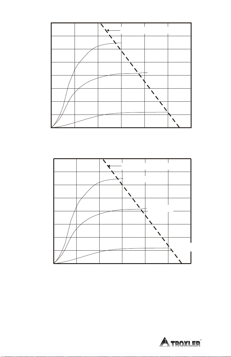
The depth of measurement is defined in terms of a maximum depth
beneath the surface of the material being measured. Of the neutrons
counted by the gauge, 98 percent will penetrate no deeper than the
depth of measurement. The depth of measurement is a function of
moisture content. The following equations can be used to determine
the approximate depth of measurement.
Depth (inches) = 11 – (0.17
Depth (mm) = 280 – (0.27
The normalized curve set shown in Figure 2–1 illustrates the effects
of moisture content on the depth of measurement.
×
M), where: M = moisture in pcf
or
×
M), where: M = moisture in kg/m3
2. OPERATION THEORY
Model 3430 Plus & 3440 Plus 2–3
Page 26
40
Depth = 11 - (0.17 X M)
35
30
25
E
32.3 pcf
S
20.8 pcf
3
336 kg/m
5.95 pcf
12
3
96 kg/m
Gauge Measured Moisture Content (pcf)
3
20
15
10
5
0
0
)
640
560
480
400
320
240
160
80
Gauge Measured Moisture Content (kg/m
0
0 50 100 150 200 250 300
24
6810
Depth (in)
Depth = 280 - (0.27 X M)
521 kg/m
Depth (mm)
The dotted lines indicate the maximum depth of gauge
measurement at a given soil moisture content.
Figure 2–1. Effect of Moisture on Depth of Measurement
3
2–4
Page 27

CALIBRATION
Troxler calibrates the gauge at the factory and recommends that it
always be calibrated by an authorized Troxler service center. For a
list of Troxler and authorized Troxler service centers, refer to page
iii of this manual or visit the Troxler website at
www.troxlerlabs.com/SERVICES/services.shtml
The operating range of the gauge is from 1100 to 2700 kg/m
(approximately 70 to 170 pcf).
OFFSETS
The factory calibration provides accurate results for the majority of
materials encountered in construction. If the gauge is to be used to
test materials not covered by the factory calibration, the readings
can be adjusted using an offset.
Perform a density offset if the test material is outside the density
range for average soil or if the material composition varies from
average soil/asphalt. Perform a moisture offset if the test material
contains hydrogenous materials (other than water) or materials that
absorb neutrons. Materials such as cement, gypsum, coal, mica, and
lime all contain chemically bound hydrogen that will cause the
gauge to display a moisture content that is higher than actual.
Material such as boron and cadmium are neutron absorbers and will
cause the gauge to display a moisture count that is lower than actual.
Vertical structures scatter neutrons and gamma photons back to the
gauge. This could result in inaccurate moisture and density readings.
To take readings in a trench or within 0.6 m (2 ft) of a large vertical
structure, perform a trench offset.
.
3
2. OPERATION THEORY
Model 3430 Plus & 3440 Plus 2–5
Page 28

NOTES
2–6
Page 29

CHAPTER 3
GETTING STARTED
This chapter provides details on getting started with the Model 3430
Plus and 3440 Plus Surface Moisture-Density Gauges. It describes
the gauge keypad, and provides instructions for conducting daily
gauge inspections, turning the gauge on, and setting up the gauge.
CONTENTS
Gauge Illustration ......................................................................... 3–2
Control Panel................................................................................ 3–3
Source Rod Positions.................................................................... 3–5
Daily Inspection............................................................................ 3–6
Turning the Gauge On .................................................................. 3–7
Setup............................................................................................. 3–9
Setup Menu ............................................................................ 3–9
Extended Menu .................................................................... 3–11
Measurement Mode.............................................................. 3–15
Project Function ................................................................... 3–16
Display Backlight................................................................. 3–16
3. GETTING STARTED
Model 3430 Plus & 3440 Plus 3–1
Page 30

GAUGE ILLUSTRATION
Figure 3–1 illustrates various components of the gauge referred to
throughout this chapter and the remainder of the manual.
3–2
Figure 3–1. Gauge Illustration
Page 31

CONTROL PANEL
The gauge control panel (see Figure 3–2) contains the power switch,
display, USB port (only on the Model 3440 Plus), battery charging
indicator, charger connector, RS-232 port, and keypad.
The keypad allows the operator to access the gauge software.
Troxler designed the keypad for ease of use, with large keys and an
anti-glare coating. Pressing a function key activates the function
only when the Ready screen is displayed. Table 3–1 describes the
function of each key.
POWER SWITCH
-Ready04-08-2007 10:39 AM
Prj: TROXLER
Press <START>
3. GETTING STARTED
USB PORT*
BATTERY
CHARGING
INDICATOR
CHARGER
CONNECTOR
RS-232 PORT
* The USB port is included only on the Model 3440 Plus.
Figure 3–2. Control Panel
Model 3430 Plus & 3440 Plus 3–3
Page 32

Table 3–1. Keypad Functions
KEY FUNCTION PAGE
〈STORE〉
〈RECALL〉
〈PROJ〉
〈STATUS〉
〈SETUP〉
〈OFFSET〉
Store the most recent data in the
current project file.
Display the most recent data. 4–17
Select or create a project file and view,
output, or erase project data file.
Displays gauge status information. 3–9
Displays the gauge Setup menu.
Enable, disable, or change a density,
moisture, or trench offset.
Select, enter, or disable a Gmb
〈TARGET〉
(Marshall), Proctor, or Gmm (Voidless
density) value.
〈MODE〉
〈STD〉
〈SPACE〉
〈LIGHT〉
〈YES〉
〈NO〉
〈ESC〉
〈0〉 .. 〈9〉
〈.〉
〈ALPHA LOCK〉
〈BACK SPACE〉
〈↑〉, 〈↓〉
〈ENTER/START〉
〈A〉 .. 〈Z〉
Select the measurement mode,
Asphalt or Soil.
Take a standard count. 4–2
Enter a space.
Manually toggle the LCD and keypad
backlights on and off.
Respond yes to yes/no questions.
Respond no to yes/no questions.
Return the display to the Ready screen
without storing or updating the data.
Enter numbers and access menu
options.
Enter a decimal point.
Access the letters.
Moves cursor back one space.
Scroll through menu options or view
screens.
Accept data entry or begin a
measurement.
Enter letters. Access these keys by
first pressing 〈ALP HA LOCK〉.
4–13, 4–16,
8–14
8–2
5–3
7–2
6–2
3–15
3–16
3–4
Page 33

SOURCE ROD POSITIONS
As shown in Figure 3–3, the source rod can be placed in the SAFE,
backscatter, or direct transmission positions. When not taking
measurements, keep the source rod in the SAFE position. When
measuring thin layer or other materials through which you cannot
drill a hole, use the backscatter position. In the direct transmission
positions, the source rod extends into a pre-drilled hole.
WARNING
The source rod should always be in the SAFE
position when the gauge is not in use.
BS
2"
50mm
3"
75mm
4"
100mm
5"
125mm
6"
150mm
7"
175mm
8"
200mm
9"
225mm
10"
250mm
11"
275mm
12"
300mm
Figure 3–3. Source Rod Positions
(Maximum Depth of 300 mm in Increments of 50 mm)
Model 3430 Plus & 3440 Plus 3–5
3. GETTING STARTED
Page 34

DAILY INSPECTION
The gauge should be inspected daily before use to ensure proper
operation of all safety features. Refer to page A–10 for the daily
inspection procedure.
3–6
Page 35

TURNING THE GAUGE ON
To turn on the gauge, press the power switch. Upon power-up, the
gauge briefly displays the model number, software version, and
serial number as shown below.
-Model 3440 Plus-
Vx.xx SN: xxx
The software then performs a brief self-test, followed by a display
test to ensure that the gauge is working properly. Following the two
tests, the gauge enters a 300-second warmup period.
NOTE
To bypass the warmup period, press 〈ESC〉.
Following the warmup period, the gauge displays the Ready
screen:
3. GETTING STARTED
-READY- g
04-08-2007 12:21 PM
Prj: TROXLER
Press <START>
NOTE
The symbol g in the upper right of the display indicates
that the GPS option (see page 5–17) is installed, the
option is enabled, and the gauge is receiving GPS
satellite signals. This option is available only on the
Model 3440 Plus.
The operator can access any gauge function from the Ready screen.
The Ready screen displays the current date and time, as well as the
current project (see Chapter 8), if any.
Model 3430 Plus & 3440 Plus 3–7
Page 36

NOTE
If the gauge display is difficult to read in bright light,
adjust the contrast as described in the Display Contrast
section on page C–9.
After 5 hours of no activity, the gauge automatically performs a
total power shutdown.
NOTE
If the charge calibration (see page C–11) is BAD, the
gauge will not perform an automatic shutdown.
3–8
Page 37

SETUP
After turning the gauge on for the first time, set up the software
parameters described in the following sections. Several of these
parameters accessed from the gauge’s Setup and Extended
menus. Other parameters are accessed via dedicated function keys.
The gauge stores the software setup, so the operator does not need
to enter a new setup each time the gauge is turned on. The setup
may be changed at any time, however.
The gauge offers a Status function that enables the operator to view
selected information concerning the current gauge status and setup.
To access the Status function, press the 〈STATUS〉 key. The gauge
displays two screens of information, including the measurement
units, count time, measurement mode, battery status, Gmb
(Marshall) value, Proctor value, Gmm (Voidless density) value, and
measurement depth. Use the arrow keys to scroll between the two
screens.
SETUP MENU
The gauge provides three different count times to be used in taking
measurements. The gauge can also display measurement results in
either U.S. units (pcf) or metric (SI) units (kg/m
Model 3440 Plus gauge offers two depth modes: automatic and
manual. These settings are accessed from the gauge’s Setup menu.
To display this menu, press the 〈SETUP〉 key. For information on
all of the functions available from the Setup menu, see Chapter 5.
Count Time
The count time defines how long the gauge reads (15 seconds, 1
minute, or 4 minutes). Longer count times produce better
measurement precision. Troxler recommends a count time of
1 minute for most sample measurements.
3
or g/cm3). The
3. GETTING STARTED
Model 3430 Plus & 3440 Plus 3–9
Page 38

To change the count time, press 〈1〉 at the Setup menu. The gauge
displays:
Time: 1 m
1. 15 sec
2. 1 min
3. 4 min
The gauge displays the current count time on the first line and
options on subsequent lines. To select the desired count time, press
the corresponding number key. The gauge sets the new count time,
then returns to the Setup menu.
Set Units
The gauge can display measurement results in either U.S. units (pcf)
or metric (SI) units (kg/m
the Setup menu. The gauge displays:
3
or g/cm3). To select the units, press 〈2〉 at
-Units-
1. pcf
2. kg/m3
3. g/cm3
Select the new units using the corresponding number key. The
gauge displays the new units, then returns to the Setup menu.
Depth Mode
The Model 3440 Plus gauge offers two depth modes: Automatic and
Manual. In the Automatic mode, the gauge software determines the
source rod depth automatically. In the Manual mode, the operator
must enter the source rod depth at a gauge prompt whenever taking
a measurement.
NOTE
The Automatic depth mode is not available on the Model
3430 Plus gauge.
3–10
Page 39

The Depth Mode function allows the operator to set the depth mode.
To access this function, press 〈2〉 at the Setup menu shown on page
5–3. The gauge displays:
Mode: Manual
1. Manual
2. Auto
Press # to Select
Select the desired depth mode using the corresponding number key.
After the depth mode is selected, the gauge sets the mode and
returns to the Setup menu.
EXTENDED MENU
The gauge is shipped with the current date and time (Eastern
Standard Time) stored in its memory. In addition, the gauge can
store a user ID and customer name. These settings are accessed
from the Extended menu. This menu includes functions that are
intended for use by authorized personnel only, and requires the use
of the access code shown on page xiii.
To access the Extended menu, press 〈.〉 〈9〉 at the Setup menu.
The gauge requests an access code:
3. GETTING STARTED
Input Access Code
_
Press <ENTER>
Enter the access code shown on page xiii and press the
〈ENTER/START〉 key. The gauge displays the Extended menu.
After setting the date and time, user ID, and/or customer name as
described in the following sections, press 〈ESC〉 to return to the
Setup menu.
For information on all of the functions available from the
Extended menu, refer to Chapter 9.
Model 3430 Plus & 3440 Plus 3–11
Page 40

Clock/Calendar
The Clock/Calendar function allows the operator to change the date
and time, and to select the display format for each. To access the
Clock/Calendar menu, press 〈1〉 at the Extended menu. The
gauge displays the Clock/Calendar menu:
-Clock/Calendar-
1. Change Time
2. Change Date
3. Time Format
-Clock/Calendar-
4. Date Format
Use the up and down arrows to scroll between the menu options. To
select a menu option, press the corresponding numeric key. To
return to the Extended menu, press the 〈ESC〉 key.
CHANGE TIME. To change the time, press 〈1〉 at the
Clock/Calendar menu. The gauge displays:
hh:mm AM
Arrows toggle AM/PM
Input Time and
Press <ENTER>
(Note that in this example, the time is displayed in AM/PM format.
To change the format, see the Time Format section on the following
page.) To accept the displayed time, press 〈ENTER/START〉. To
change the time, use the numeric keys to enter the new time, and the
arrow keys to toggle between AM and PM. Press
〈ENTER/START〉. The gauge sets the time and returns to the
Clock/Calendar menu.
3–12
Page 41

CHANGE DATE. To change the date, press 〈2〉 at the
Clock/Calendar menu. The gauge displays:
04/08/2006
mm/dd/yyyy
Input Date and
Press <ENTER>
(Note that in this example, the time is displayed in mm/dd/yyyy
format. To change the date format, refer to the Date Format section
below.) To accept the displayed date, press 〈ENTER/START〉. To
change the date, use the numeric keys to enter the new date. When
finished, press 〈ENTER/START〉. The gauge sets the date and
returns to the Clock/Calendar menu.
TIME FORMAT. The gauge can display the time in either AM/PM
or 24-hour format. To select the desired time format, press 〈3〉 at the
Clock/Calendar menu. The gauge displays:
-Time Format-
1. AM/PM
2. 24-Hour
Use the numeric keys to select the desired time format. The gauge
sets the time format and returns to the Clock/Calendar menu.
DATE FORMAT. The gauge can display the date in either
mm/dd/yyyy or dd/mm/yyyy format, where mm = month, dd = day,
and yyyy = year. To select the desired date format, press 〈4〉 at the
Clock/Calendar menu. The gauge displays:
-Date Format-
1. mm/dd/yyyy
2. dd/mm/yyyy
Use the numeric keys to select the desired format. The gauge sets
the date format and returns to the Clock/Calendar menu.
Model 3430 Plus & 3440 Plus 3–13
3. GETTING STARTED
Page 42

User ID
The gauge can store a three-character alphanumeric user ID with
each measurement. To enter or change the user ID, press 〈2〉 at the
Extended menu. The gauge displays:
User ID is:
XXX
Change ID?
<YES> or <NO>
To change the user ID, press 〈YES〉. The gauge displays:
User ID: A
Input ID and
Press <ENTER>
Press the 〈ALPHA LOCK〉 key to enable the alphabetic keys on the
gauge. When the alphabetic keys are enabled, the symbol A appears
in the upper right of the display, as shown above.
Enter the new user ID and press 〈ENTER/START〉. The gauge
stores the new user ID and returns to the Extended menu.
Customer Name
The gauge can store a customer name of up to 12 alphanumeric
characters. To enter a customer name, press 〈3〉 at the Extended
menu. The gauge displays the current customer name on the second
line.
3–14
Customer Name is:
CUSTOMER
Change Name?
<YES> or <NO>
Page 43

To change the customer name, press 〈YES〉. The gauge displays:
Customer Name: A
Input Name and
Press <ENTER>
Press the 〈ALPHA LOCK〉 key to enable the alphabetic keys on the
gauge. When the alphabetic keys are enabled, the symbol A appears
in the upper right of the display, as shown above.
Enter the new name and press the 〈ENTER/START〉 key. The
gauge stores the new customer name, then returns to the Extended
menu.
Press 〈ESC〉 twice to return to the Ready screen.
MEASUREMENT MODE
The gauge provides two measurement modes (Soil and Asphalt) for
precise readings on base asphalt, concrete, soil, soil-stone aggregate,
and similar materials. The gauge can also be used to determine the
density of thin-layer overlays using the Nomograph function
described on page 5–10.
Before taking a measurement, select the appropriate measurement
mode.
To select the measurement mode, press the 〈MODE〉 key. The gauge
displays:
3. GETTING STARTED
Mode: Asphalt
1. Asphalt
2. Soil
Press # to Select
NOTE
The 〈MODE〉 key is active only when the Ready screen
is displayed.
Model 3430 Plus & 3440 Plus 3–15
Page 44

The current mode (Asphalt, Soil, or Nomograph) is displayed on the
top line of the display. Use the Soil mode when measuring soil or a
soil-stone aggregate. Use Asphalt mode when measuring concrete or
asphalt layers of 4 inches or greater. Use the number keys to select
either Asphalt or Soil mode, or refer to page 5–10 for instructions on
enabling the Nomograph function for taking thin-layer
measurements. The gauge enables the selected measurement mode
and returns to the Ready display.
PROJECT FUNCTION
The gauge allows unique project names to be entered into the gauge
memory. Subsequent measurements can then be stored under these
project names. To access the Project function, press the 〈PROJ〉
key.
NOTE
The 〈PROJ〉 key is active only when the Ready screen is
displayed.
Chapter 8 provides detailed instructions on the Project function.
DISPLAY BACKLIGHT
Both the Model 3430 Plus and 3440 Plus gauges provide a backlight
for the liquid crystal display (LCD). The backlight can help the
operator read the display at night. The Model 3440 Plus also
features a backlit keypad; this feature is not available on the Model
3430 Plus gauge. To activate the backlight, press the 〈LIGHT〉 key.
NOTE
Using the display backlight reduces the battery life. To
conserve battery life, turn the backlight off when it is
not needed. Also note that the backlight turns off
automatically after 3 minutes to conserve power.
3–16
Page 45

NOTE
The gauge also features a hardware adjustment for the
display contrast. If the gauge display is difficult to read
in bright light, adjust the contrast as described in the
Display Contrast section on page C–9.
Model 3430 Plus & 3440 Plus 3–17
3. GETTING STARTED
Page 46

NOTES
3–18
Page 47

CHAPTER 4
USING THE GAUGE
This chapter explains the basic use of the Troxler Model 3430 Plus
and 3440 Plus Surface Moisture-Density Gauges. Basic use includes
taking the daily standard count, preparing measurement sites, setting
the measurement mode, and taking measurements.
CONTENTS
Taking a Standard Count .............................................................. 4–2
New Standard Count .............................................................. 4–3
View Standard Counts............................................................ 4–6
Preparing a Test Site..................................................................... 4–7
Soil Site.................................................................................. 4–7
Asphalt Site............................................................................ 4–9
Taking Measurements................................................................. 4–10
Soil Mode............................................................................. 4–11
Asphalt Mode....................................................................... 4–14
Recall.......................................................................................... 4–17
4. USING THE GAUGE
Model 3430 Plus & 3440 Plus 4–1
Page 48

TAKING A STANDARD COUNT
To adjust readings for source decay (see Appendix A) and natural
background radiation, take a daily standard count. A four-minute
daily standard count helps ensure the highest measurement
accuracy.
Locate the reference standard block shipped with the gauge.
NOTE
Always take standard counts using the reference
standard block provided with the gauge.
Before taking a standard count, ensure that the gauge base and
reference standard block are dry and free of debris.
Choose a standard count site that meets the following criteria:
♦ A smooth surface such that the reference standard block does
not rock
♦ At least 3 meters (10 ft) from any large vertical surface
♦ At least 10 meters (33 ft) from any other radioactive source
♦ On asphalt, concrete, or compacted soil at least 10 centimeters
(4 in.) thick
Turn the gauge on. At the Ready display, press the 〈STD〉 key. The
gauge displays the last standard counts for density (DS) and
moisture (MS).
Standard Count
DS= ####
MS= ####
Take New Count?
NOTE
The 〈STD〉 key is active only when the Ready screen is
displayed.
To take a new standard count, press 〈YES〉 and follow the
instructions in the New Standard Count section that follows.
To view the last four standard counts, press 〈NO〉 and follow the
instructions in the View Standard Counts section on page 4–6.
4–2
Page 49

NEW STANDARD COUNT
When taking a new standard count, the gauge displays:
Place Gauge on
Std. Block & Source
Rod in SAFE Pos.
Press <ENTER>
Place the reference standard block on the standard count site. As
shown in Figure 4–1, place the gauge on the reference standard
block, with the right side (keypad side) of the gauge against the
metal butt plate.
NOTE
Ensure that the source rod is in the standard (SAFE)
position and is securely seated by firmly tapping down
on the handle of the source rod.
Figure 4–1. Standard Count Position
Model 3430 Plus & 3440 Plus 4–3
4. USING THE GAUGE
Page 50

Begin the standard count by pressing the 〈ENTER/START〉 key.
The gauge displays:
Taking
Standard Count
### s
Remaining
After taking the standard count, the gauge displays the results:
DS= #### ##.#% P
MS= #### ##.#% P
Do You Want to
Use the New Std.?
Troxler recommends that the operator keep a daily log of the
moisture and density standard counts (see Appendix D). To verify
gauge stability, compare the daily standard count to a reliable
reference as follows:
♦ During the first four days of operation of a new or recalibrated
gauge, compare the daily standard count to the factorycalibrated values (which are shown on the calibration report sent
with the gauge).
♦ After the first four days of operation (or after taking four
standard counts), compare the daily standard count to the
average of the last four counts. Acceptable standard count limits
are:
±1.0% for DS (density standard) and
±2.0% for MS (moisture standard).
If the standard count passes, record the standard counts, then
press the 〈YES〉 key. The gauge returns to the Ready screen.
NOTE
The factory standard count values should be used as a
reference if the daily standard counts are ever in
question. Be sure to refer to the most recent calibration
report for the gauge in question.
4–4
Page 51

If the standard count fails and it has been more than a month
since the last standard count, then accept the standard count by
pressing the 〈YES〉 key. At the Do You Want To Erase Last
Four Standard Counts? prompt, press the 〈YES〉 key. The
gauge displays:
Depth Calibration
Set Rod To BS.
And Press ENTER
Follow the displayed instructions, and take four additional
standard counts. The last of these counts will be compared to
the previous four, and the standard counts should pass. If not,
repeat the procedure. If it still fails, perform a stat test (see page
5–5) and a drift test (see page 5–7), then contact your Troxler
representative.
If the standard count fails and it has been less than a month
since the last standard count, but the count was performed
correctly and the failure is less than 5%, press the 〈YES〉 key. If
the failure is more than 5%, press the 〈NO〉 key. Ensure that the
gauge is properly positioned on the reference standard block
(Figure 4–1). Verify that the standard count site meets the
criteria listed on page 4–2. Take another standard count and
accept it if it fails by less than 5%. If the standard count fails
four times, perform a stat test (see page 5–5) and a drift test (see
page 5–7), then contact your Troxler representative.
After the standard count passes, the operator can take measurements
with the gauge. When not taking readings, always keep the source
rod in the SAFE position. For added user safety, the source rod
automatically retracts to the SAFE position when the gauge is lifted
using the handle.
4. USING THE GAUGE
Model 3430 Plus & 3440 Plus 4–5
Page 52

VIEW STANDARD COUNTS
To view the last four standard counts, press 〈NO〉 at the display
shown at the bottom of page 4–2. The gauge displays:
Standard Count
Want to View
Last Four Counts?
<YES> or <NO>
Press 〈YES〉 to view the last four standard counts. The gauge
displays the last four density standard counts. Press 〈YES〉 to
view the last four moisture standard counts. Press
〈ENTER/START〉 to return to the Ready screen.
Press 〈NO〉 to return to the Ready screen.
4–6
Page 53

PREPARING A TEST SITE
To ensure measurement accuracy, properly prepare the test site
before taking gauge measurements. This section describes how to
prepare test sites properly for soil and asphalt measurements.
SOIL SITE
Locate a smooth site on the soil that is free from any large
holes, cracks, or debris.
If necessary, smooth the surface by moving the scraper plate in
a back and forth motion.
Fill any voids or depressions with fine sand or soil particles.
Strike off any excess fill.
Place the scraper plate back on the surface and press down
slightly to level the surface.
WARNING
Under no circumstances should the source rod of the
gauge be used to drill holes.
For direct transmission measurements:
Put the drill rod through the extraction tool and then through
one of the guides on the scraper plate (Figure 4–2).
Wear safety glasses and a radiation dosimeter.
Place the drill rod assembly on the test site.
Step on the scraper plate.
Hammer the drill rod at least 50 mm (2 in.) deeper than the
desired test depth. The drill rod increments include the
additional depth.
Before removing the drill rod, mark the outline of the scraper
plate as shown in Figure 4–3 to ensure the gauge is placed over
the same area as the scraper plate.
Model 3430 Plus & 3440 Plus 4–7
4. USING THE GAUGE
Page 54

Figure 4–2. Drill Rod Assembly
Remove the drill rod by pulling straight up and twisting the
extraction tool. Do not loosen the drill rod by tapping from side
to side with a hammer. Also, do not rock the extraction tool
from side to side. This will distort the hole or cause loose
material to fall into the hole.
Carefully pick up the scraper plate.
EDGE
PLATE CENTER
MARKSMARK FOR SCRAPER
4–8
SCRAPER
PLATE
METHOD 1
SCRAPER
MARK FOR DRILL
ROD CENTER
PLATE
METHOD 2
Figure 4–3. Marking the Test Area
Page 55

ASPHALT SITE
This also applies to hardened concrete sites and soil.
NOTE
These directions also apply to taking a backscatter
measurement on soil.
Locate a smooth site on the asphalt.
Fill the voids on open mixes with sand or cement. The gauge
base must rest on the asphalt, not the fill material!
Ensure that the gauge does not rock. To ensure accurate
readings, the gauge base must be completely in contact with the
test material. If the gauge rocks, then find a more suitable test
site. If taking a measurement around a core, the gauge may be
moved a few inches away from the core to level it.
Model 3430 Plus & 3440 Plus 4–9
4. USING THE GAUGE
Page 56

TAKING MEASUREMENTS
WARNING
When not taking readings, always keep the source
rod in the SAFE (shielded) position. For added user
safety, the source rod automatically retracts to the
SAFE position when the gauge is lifted by the
handle.
If you do not hear a click when the gauge is raised to the SAFE
position, look at the bottom of the gauge to verify that the tungsten
sliding block is completely closed. If the gauge base opening is not
completely closed by the sliding block, the block may require
cleaning. Refer to page A–11 for cleaning instructions.
WARNING
Do not store or transport the gauge unless the
sliding block is completely closed. Increased
radiation levels may cause excessive personnel
radiation exposure and may violate transportation
regulations.
The Status function (see page 3–9) allows the operator to view
selected information concerning the current gauge status and setup.
To access the Status function, press the 〈STATUS〉 key. Check the
gauge’s current status before taking measurements.
Remember to take a standard count at least once each day the gauge
is to be used (see page 4–2). Note that some states may require that
a standard count be taken more frequently than once per day.
The gauge can store measurement results in files (memory
locations) called projects. For information on creating and
activating project files, refer to Chapter 8. Upon completion of a
measurement, the results can be stored either automatically by
enabling the Auto-Store function (see page 8–12) or manually by
using the Store function (see page 8–14).
4–10
Page 57

SOIL MODE
To measure the moisture and density of soil, soil-stone aggregate,
and similar materials, follow the steps below:
Select the Soil mode (see page 3–15).
If desired, enter, change, or enable the Proctor value as
described in Chapter 6.
Prepare the test site as described on page 4–7.
Place the gauge on the test area.
Insert the source rod into the hole made by the drill rod. Use
care when inserting the source rod. Try not to disturb the soil
around the hole.
Lower the source rod to the measurement depth. Release the
trigger. Gently push the handle down to lock the source rod into
position. You should hear a click when the source rod locks into
position.
Gently slide the gauge to the right (towards the keypad) so the
source rod makes contact with the wall of the hole.
Press the 〈ENTER/START〉 key.
In the Manual depth mode (see page 5–4), the gauge
prompts for the source rod depth. Enter the source rod depth
using the number keys. For example, with the source rod in
the backscatter position, press 〈0〉. Then press
〈ENTER/START〉.
In the Automatic depth mode (available only on the Model
3440 Plus), the gauge software determines the source rod
depth automatically.
Note that the Proctor value is based on soil particles 3/8
inches or less in diameter (or those passing a #4 sieve). If an
unusual reading is obtained and oversize particles are
suspected, rotate the gauge 90°. Use the same drill hole to
take a second reading.
Model 3430 Plus & 3440 Plus 4–11
4. USING THE GAUGE
Page 58

The gauge displays the time remaining while taking a
measurement.
After the count time, the gauge displays the measurement
results:
%PR= ###.#
DD= ##.#
WD= ###.#
M= ##.# %M= ##.#
Lat: +hh mm ss.ss
Lng: -hh mm ss.ss
where: %PR = percent Proctor %M = percent moisture
DD = dry density Lat = latitude
WD = wet density Lng = longitude
M = moisture
NOTE
The latitude and longitude display, showing the location
of the measurement, is available only on Model 3440
Plus gauges equipped with the GPS option and is shown
only when this option is enabled.
The latitude and longitude values denote the quality of
the location fix. If WAAS information is available
during a gauge measurement, the latitude and longitude
will be displayed to the nearest hundredth (1/100) of a
second. If a GPS location is determined, but the WAAS
information is unavailable, the latitude and longitude
will be displayed to the nearest tenth (1/10) of a second.
If the GPS receiver cannot determine a location, the
latitude and longitude will be denoted as 0. For more
information on GPS accuracy, see Appendix I.
4–12
Page 59

If a project is active (see Chapter 8) and the Auto-Store
function (see page 8–12) is enabled, press 〈ESC〉 or
〈ENTER/START〉 to continue. For each measurement, the
gauge can store a location description of up to 12
characters, as well as a note of up to 15 characters. Follow
the prompts to enter location information and/or a note.
If a project is active but the Auto-Store function is not
enabled:
Press 〈STORE〉
to enter location information and/or notes. For more
information on storing results manually, see page 8–14.
Press 〈ESC〉 to return to the Ready screen without
storing the results. Note that, until another measurement
has been taken, the results can be recalled as described
on page 4–17 and stored later.
Lift the gauge from the test site by the source rod handle. This
returns the source rod to the SAFE position. When not taking
readings, always keep the source rod in the SAFE position.
to store the results. Follow the prompts
4. USING THE GAUGE
Model 3430 Plus & 3440 Plus 4–13
Page 60

ASPHALT MODE
To measure the density of asphalt (and hardened concrete of 4
inches or more) follow the steps below:
Select the Asphalt mode (see page 3–15).
If desired, enter or enable the Marshall value and/or voidless
density value as described in Chapter 6.
Prepare the test site as described on page 4–9.
Place the gauge on the test area.
Lower the source rod to the backscatter position (just below the
SAFE position). Release the trigger. Gently push the handle
down to lock the source rod into position. You should hear a
click when the source rod locks into position.
Press the 〈START〉 key.
In the Manual depth mode (see page 5–4), the gauge
prompts for the source rod depth. Enter the source rod depth
using the number keys. For example, with the source rod in
the backscatter position, press 〈0〉. Then, press
〈ENTER/START〉.
In the Automatic depth mode (available only on the Model
3440 Plus), the gauge software determines the source rod
depth automatically.
The gauge displays the time remaining while taking a
measurement.
4–14
Page 61

After the count time, the gauge displays the measurement
results:
%Gmb= ###.#
WD= ###.#
M= ##.# %M= ##.#
%Voids= ###.#
Lat: +hh mm ss.ss
Lng: -hh mm ss.ss
where:
%Gmb = percent of laboratory bulk density
WD = wet density
M = moisture value
%M = percent moisture
−×=
1100%Voids
WD
Voidless
⎛
⎜
⎝
(displayed only when enabled)
⎞
⎟
⎠
Lat = latitude
Lng = longitude
NOTE
The latitude and longitude display, showing the location
of the measurement, is available only on Model 3440
Plus gauges equipped with the GPS option and is shown
only when this option is enabled.
The latitude and longitude values denote the quality of
the location fix. If WAAS information is available
during a gauge measurement, the latitude and longitude
will be displayed to the nearest hundredth (1/100) of a
second. If a GPS location is determined, but the WAAS
information is unavailable, the latitude and longitude
will be displayed to the nearest tenth (1/10) of a second.
If the GPS receiver cannot determine a location, the
latitude and longitude will be denoted as 0. For more
information on GPS accuracy, see Appendix I.
Model 3430 Plus & 3440 Plus 4–15
4. USING THE GAUGE
Page 62

If a project is active (see Chapter 8) and the Auto-Store
function (see page 8–12) is enabled, press 〈ESC〉 or
〈ENTER/START〉 to continue. For each measurement, the
gauge can store a location description of up to 12
characters, as well as a note of up to 15 characters. For an
Asphalt mode measurement, the gauge can also store
location with respect to the centerline (left, right, or
neither), and the distance from the centerline. Follow the
prompts to enter location information and/or a note.
If a project is active but the Auto-Store function is not
enabled:
Press 〈STORE〉
to enter location information and/or notes. For more
information on storing results manually, see page 8–14.
Press 〈ESC〉 to return to the Ready screen without
storing the results. Note that, until another measurement
has been taken, the results can be recalled as described
on page 4–17.
Lift the gauge from the test site using the source rod handle.
This returns the source rod to the SAFE position. When not
taking readings, always keep the source rod in the SAFE
position.
to store the results. Follow the prompts
4–16
Page 63

RECALL
To view the results of the most recent measurement, press the
〈RECALL〉 key from the Ready screen. To return to the Ready
screen, press the 〈ENTER/START〉 key.
NOTE
The 〈RECALL〉 key is active only when the Ready
screen is displayed.
NOTE
The Recall function can also be used to view the gauge
counts from the most recent measurement.
Model 3430 Plus & 3440 Plus 4–17
4. USING THE GAUGE
Page 64

NOTES
4–18
Page 65

CHAPTER 5
SETUP MENU
The gauge software includes a Setup menu that allows the operator
to manually set or change operating parameters of the gauge. This
chapter describes these parameters.
CONTENTS
Setup Menu................................................................................... 5–3
Count Time................................................................................... 5–4
Set Units........................................................................................ 5–4
Depth Mode.................................................................................. 5–4
Stat Test........................................................................................ 5–5
Taking a Stat Test................................................................... 5–5
Reviewing the Stat Test.......................................................... 5–6
Printing the Stat Test.............................................................. 5–6
Drift Test....................................................................................... 5–7
Taking a Drift Test................................................................. 5–8
Reviewing the Drift Test........................................................ 5–9
Printing the Drift Test ............................................................ 5–9
Nomograph................................................................................. 5–10
Enable Nomograph............................................................... 5–11
Disable Nomograph.............................................................. 5–11
Change/View Nomograph Data ........................................... 5–11
Taking Nomograph Measurements...................................... 5–14
5. SETUP MENU
Model 3450 5–1
Page 66

CONTENTS (Continued)
Precision......................................................................................5–15
Options........................................................................................5–17
External Beeper.....................................................................5–17
GPS Option...........................................................................5–17
Battery Status ..............................................................................5–18
Percent Air Voids (Soil Mode)....................................................5–19
5–2
Page 67

SETUP MENU
The gauge software groups most of the setup features into one
menu. To access the Setup menu, press the 〈SETUP〉 key. The
gauge displays:
-Setup-
1. Count Time
2. Set Units
3. Depth Mode
-Setup-
4. Stat Test
5. Drift Test
6. Nomograph
-Setup-
7. Precision
8. Options
9. Battery Status
5. SETUP MENU
-Setup-
.0-% Voids (soil)
NOTE
The 〈SETUP〉 key is active only when the Ready screen
is displayed.
Use the arrows keys to scroll through the menu screens. To select a
menu option, use the number key that corresponds to that option.
The remainder of this section provides details on the functions
available from the Setup menu.
Model 3450 5–3
Page 68

COUNT TIME
The gauge provides three different count times for taking
measurements. The Count Time function is described on page 3–9.
SET UNITS
The gauge can display measurement results in either U.S. units (pcf)
or metric (SI) units (kg/m
described on page 3–10.
3
or g/cm3). The Set Units function is
DEPTH MODE
The Model 3440 Plus gauge offers two depth modes: Automatic and
Manual. The Depth Mode function allows the operator to set the
depth mode, as described on page 3–10.
5–4
Page 69

STAT TEST
Erratic readings, or readings that seem to fluctuate, may indicate a
problem with the gauge. If the readings are suspect, perform a stat
test, or statistical stability test, to validate the normal operation of
the gauge.
A stat test consists of twenty 1-minute counts. From the twenty
counts, the gauge calculates the standard deviation. This standard
deviation is compared to a theoretical standard deviation value.
Ideally, this ratio should be 0.25, with acceptable limits from 0.17 to
0.33. The gauge is considered unstable if the ratio is outside these
limits and the stat test will fail. If the stat test fails, ensure that the
gauge setup and testing was conducted correctly, and take an
additional test. If the second test fails, contact the nearest Troxler
service center for assistance. For a list of Troxler and authorized
Troxler service centers, refer to page iii of this manual or visit the
Troxler website at www.troxlerlabs.com/SERVICES/services.shtml
To access the Stat Test function, press 〈4〉 at the Setup menu. The
gauge displays the Stat Test menu:
5. SETUP MENU
.
1. Take STAT Test
2. Review STAT Test
3. Print STAT Test
<ESC> to Exit
To select a menu option, press the corresponding numeric key or
press 〈ESC〉 to return to the Setup menu.
TAKING A STAT TEST
Choose an area free of other nuclear gauges or radioactive sources.
Place the gauge on the reference standard block as shown in Figure
4–1 on page 4–3.
To take a new stat test, press 〈1〉 at the Stat Test menu shown
above. The gauge prompts the operator to place the gauge on the
reference standard block with the source rod in the SAFE (shielded)
position. Ensure that the gauge is properly positioned and press the
〈ENTER/START〉 key.
Model 3450 5–5
Page 70

The gauge displays the progress of the stat test (twenty 1-minute
counts). Upon completion of the counts, the gauge displays the
results of the density stat test, including an indication of whether the
test passed or failed:
Density Stat Test
Avg. Counts: ####
R: #.### (PASS)
<ENTER> for Moist.
Press 〈ENTER/START〉 to view the results of the moisture stat test.
Follow the prompts to scroll through the results.
REVIEWING THE STAT TEST
To review the results of the last stat test, press 〈2〉 at the Stat Test
menu shown on page 5–5. The gauge displays the results of the
density stat test as shown above. Press 〈ENTER/START〉 to view
the results of the moisture stat test. Follow the prompts to scroll
through the results.
PRINTING THE STAT TEST
To print the results of the last stat test to a serial printer or computer
via the gauge’s 9-pin serial port, press 〈3〉 at the Stat Test menu
shown on page 5–5. The gauge prompts the operator to connect the
printer to the gauge.
Connect a serial cable to the gauge’s serial port. Ensure that the
serial cable meets the pinout shown on page F–6. An optional serial
cable, PN 113128, is available from Troxler. Connect the serial
cable to the printer or computer serial port.
Press 〈ENTER/START〉. The gauge prints or uploads the stat test
data and returns to the Stat Test menu.
5–6
Page 71

DRIFT TEST
If the gauge passes the stat test, but shows long-term drift between
measurements, perform a drift test to check the long-term drift of
the gauge. A drift test consists of five counts taken three to eight
hours after a stat test with no movement of the gauge between tests.
The gauge sets the pass/fail limits based on the percent difference
between the average of the stat test and drift test results. If the
percent difference exceeds 0.5 percent for density counts or 1
percent for moisture counts, then the drift test fails. If the drift test
fails, ensure that the gauge setup and testing were conducted
correctly, and take an additional test. If the second test fails, contact
the nearest Troxler service center for assistance. For a list of Troxler
and authorized Troxler service centers, refer to page iii of this
manual or visit the Troxler website at
www.troxlerlabs.com/SERVICES/services.shtml
NOTE
The drift test consists of five 4-minute counts, whereas
the stat test consists of twenty 1-minute counts.
Therefore, each test takes approximately 20 minutes to
conduct.
DO NOT turn the gauge off between a stat test and a
drift test.
DO NOT move the gauge between the stat and drift tests
to eliminate possible failure due to positioning changes.
To access the Drift Test function, press 〈5〉 at the Setup menu. The
gauge displays the Drift Test menu:
.
5. SETUP MENU
1. Take Drift Test
2. Review Drift Test
3. Print Drift Test
<ESC> to Exit
To select a menu option, press the corresponding numeric key or
press 〈ESC〉 to return to the Setup menu.
Model 3450 5–7
Page 72

TAKING A DRIFT TEST
To take a new drift test, press 〈1〉 at the Drift Test menu shown on
page 5–7. The gauge prompts the operator to place the gauge on the
reference standard block with the source rod in the SAFE (shielded)
position. Ensure that the gauge is properly positioned and press the
〈ENTER/START〉 key.
NOTE
If it has been less than three hours or more than eight
hours since the last stat test, the gauge displays an error
message. Press 〈ENTER/START〉 to return to the Setup
menu.
The gauge displays the progress of the drift test (five 4-minute
counts). Upon completion of the counts, the gauge displays the
results of the density drift test, including an indication of whether
the test passed or failed:
Density Drift Test
Avg. Counts: ####
R: #.### (PASS)
<ENTER> for Moist.
Press 〈ENTER/START〉 to view the results of the moisture drift
test. Follow the prompts to scroll through the results.
5–8
Page 73

REVIEWING THE DRIFT TEST
To review the results of the drift stat test, press 〈2〉 at the Drift Test
menu shown on page 5–7. The gauge displays the results of the
density drift test as shown on page 5–8. Press 〈ENTER/START〉 to
view the results of the moisture drift test. Follow the prompts to
scroll through the results.
PRINTING THE DRIFT TEST
To print the results of the last drift test to a serial printer or
computer via the gauge’s 9-pin serial port, press 〈3〉 at the Drift
Test menu shown on page 5–7. The gauge prompts the operator to
connect the printer to the gauge.
Connect a serial cable to the gauge’s serial port. Ensure that the
serial cable meets the pinout shown on page F–6. An optional serial
cable, PN 113128, is available from Troxler. Connect the serial
cable to the printer or computer serial port.
Press 〈ENTER/START〉. The gauge prints or uploads the drift test
data and returns to the Drift Test menu.
5. SETUP MENU
Model 3450 5–9
Page 74

NOMOGRAPH
In some cases, the gauge may be used to determine the density of
thin asphalt overlays. This measurement may be performed with the
gauge in backscatter mode and using the Nomograph method of
density measurement. It should be noted that this method is not as
accurate as a true thin-layer gauge. However, this method may
produce satisfactory results under many conditions.
When a nuclear gauge is used in backscatter mode on overlays
under 3 in. (7.5 cm), several effects must be overcome to produce an
accurate reading. With most gauges, the primary problem is the
result of photons from the source penetrating deeper than 3 in. (7.5
cm) and scattering back to the gauge. These backscattered photons
from the underlying material will adversely influence the reading.
Obtaining an accurate overlay density with the Nomograph method
requires that the density of the bottom layer and the thickness of the
top layer be determined. The simplest method of determining the
density of the bottom layer is to take a nuclear gauge measurement
prior to applying the top layer or overlay. With the overlay applied
and compacted, the depth of the layer should be determined. At this
time, the gauge may be used to calculate the overlay layer density.
To access the Nomograph function, press 〈6〉 at the Setup menu
shown on page 5–3. The gauge displays:
Nomograph: OFF
1. Enable
2. Disable
3. Chg/View Data
From this menu, the operator may enable, disable, or change the
Nomograph function, as described in the following sections.
5–10
Page 75

ENABLE NOMOGRAPH
To enable the Nomograph function, press 〈1〉 at the Nomograph
menu shown on page 5–10. The gauge enables the function,
displays a brief confirmation message, and returns to the Setup
menu.
DISABLE NOMOGRAPH
To disable the Nomograph function, press 〈2〉 at the Nomograph
menu shown on page 5–10. The gauge disables the function,
displays a brief confirmation message, and returns to the Setup
menu.
CHANGE/VIEW NOMOGRAPH DATA
To change or view the Nomograph data, press 〈3〉 at the
Nomograph menu shown on page 5–10. The gauge displays:
5. SETUP MENU
Thickness: #.## in
Density: ##.# pcf
Do You Want to
Change?
To return to the Setup menu without changing the Nomograph
data, press 〈NO〉.
To change the Nomograph data, press 〈YES〉. The gauge displays:
Select Method of
Entering Density
1. Keypad
2. Measure
The wet density of the underlying or base material may be entered
either manually using the keypad or by using the gauge to record
actual measurements.
Model 3450 5–11
Page 76

Entering Density Using the Keypad
To enter the density using the keypad, press 〈1〉 at the Select
Method of Entering Density display shown on page 5–11. The
gauge displays:
Overlay Thickness
#.## in
Input and <ENTER>
Enter the thickness of the overlay (from 0 to 10 in.) and press
〈ENTER/START〉. The gauge displays:
Bottom Density
#.# pcf
Input and <ENTER>
Enter the wet density of the bottom layer. The gauge enables the
Nomograph function using the entered values, displays a brief
confirmation message, and returns to the Setup menu.
Entering Density Using Gauge Measurements
Bottom density values may be obtained by using the gauge to record
up to 20 actual measurements. To enter the density using this
method, press 〈2〉 at the Select Method of Entering Density
menu shown on page 5–11. The gauge displays:
# of Readings to
Average (1-20)?
#
Input and <ENTER>
5–12
Page 77

Enter the number of readings to be taken and averaged, then press
〈ENTER/START〉. The gauge displays:
Readings: #
Time: # m
Place Rod to BS &
Press <START>
Prepare the site for measurement as described on page 4–9. Position
the gauge and press 〈ENTER/START〉. The gauge displays:
Nomograph
Reading: 1
Depth: BS
Time: ## s
After counting down to zero, the gauge displays:
5. SETUP MENU
Reading: 1
WD= ### pcf
Move Gauge and
Press <START>
If more than one reading is to be taken, move the gauge to the next
location and press 〈ENTER/START〉. The gauge will repeat the
above sequence for each reading. When all the readings are
completed, the display will be:
Average of #
Readings
### pcf
Press <ENTER>
Press 〈ENTER/START〉 to continue. The gauge enables the
Nomograph function, displays a brief confirmation message, and
returns to the Setup menu.
Model 3450 5–13
Page 78

TAKING NOMOGRAPH MEASUREMENTS
When the Nomograph function is enabled, the gauge can be used to
take thin-layer overlay measurements. Press 〈ENTER/START〉 to
begin the test. The gauge displays:
Depth: BS in
( Nomograph )
Time: xx s
After counting down to zero, the display is:
%Gmb= ####
WD= ##
( Nomograph )
This test may be stored as any other test measurement. The recall
function and/or printout will show that the Nomograph function was
used.
NOTE
The Nomograph function should be disabled before
taking any measurements not requiring this function.
5–14
Page 79

PRECISION
The gauge can produce test results with precision limits as low as
0.1 pcf (1.6 kg/m
is used to determine the count time required to achieve the precision
entered by the operator. If the precision requested is within range
and the time required to calculate the required result does not
exceed 60 minutes, the following procedure can usually produce the
required results.
To execute the Precision function, first ensure that the gauge is in
the correct mode: Soil or Asphalt. Press 〈7〉 from the Setup menu
shown on page 5–3. The gauge displays:
Enter the desired precision and press 〈ENTER/START〉. The gauge
displays:
3
) under certain conditions. The Precision function
Precision
#.# pcf
<ENTER> to Continue
5. SETUP MENU
Index: 0 in
<ENTER> to Select
<0> for BS
If the gauge is in the correct position, press 〈ENTER/START〉. The
gauge displays:
Depth: # in
1 min. count
<ENTER> to Continue
Model 3450 5–15
Page 80

Press 〈ENTER/START〉. The gauge displays:
Precision Mode
Depth: # in
Time: ## s
# min. count
After counting down to zero, the display will be:
## min. to
reach precision.
<ESC> to Abort
<ENTER> to Continue
To abort this operation and return to the Setup menu, press 〈ESC〉.
To continue with the Precision function, press 〈ENTER/START〉.
After counting down, the display will be:
(For Soil mode)
%PR= ###.#
DD= ###.#
WD= ###.#
M= ##.# %M= ##.#
(For Asphalt mode)
%Gmb= ###.#
WD= ###.#
M= ##.# %M= ##.#
%Voids= ###.#
NOTE
If the required precision cannot be reached in 60
minutes, the gauge halts the count and displays a
warning message.
5–16
Page 81

OPTIONS
The Model 3440 Plus gauge offers an external beeper and an
optional global positioning system (GPS) unit. These features can be
toggled on and off from the Options menu. To access this menu,
press 〈8〉 from the Setup menu (see page 5–3). The gauge displays:
-Options-
1. Ext. Beeper - OFF
2. GPS - OFF
EXTERNAL BEEPER
The Model 3440 Plus gauge is equipped with an external beeper.
The external beeper can be enabled or disabled as desired. To toggle
the external beeper on or off, press 〈1〉 on the Options menu shown
above.
GPS OPTION
The Model 3440 Plus gauge can also be equipped with an optional
global positioning system (GPS) receiver. The GPS receiver enables
the gauge to store precise GPS coordinates, along with the standard
date and time stamp, for each measurement.
To toggle the GPS function on or off, press 〈2〉 on the Options
menu shown above.
NOTE
When the GPS option is installed and enabled, the
symbol g appears in the upper right of the Ready
screen (see page 3–7) when the gauge is receiving GPS
satellite signals.
5. SETUP MENU
Model 3450 5–17
Page 82

BATTERY STATUS
The Battery Status function displays the voltage of the NiMH
batteries, the charge percentage, and the status of the charge
calibration. To access this function, press 〈9〉 at the Setup menu
shown on page 5–3.
For more information, see the Battery Status section on page C–10.
For more information on the charge calibration, see page C–12.
5–18
Page 83

PERCENT AIR VOIDS (SOIL MODE)
The gauge uses the specific gravity function to calculate percent air
voids and void ratio in Soil mode only. The % Voids function allows
the operator to enter the specific gravity of a material and disable or
enable the percent air voids display.
NOTE
To display percent air voids in Asphalt mode, enter a
voidless density target value (see the Target Values
section that begins on page 6–3.
To access the % Voids function, press 〈.〉 〈0〉 at the Setup menu
shown on page 5–3. The gauge displays:
% Voids (soil): OFF
SG: #.##
1. Enable 2. Disable
3. Change Target
5. SETUP MENU
The current specific gravity (default 2.70) is shown on the second
line of the display. For optimum results, use a specific gravity value
that is appropriate for the material being measured.
To enable the current specific gravity value, press 〈1〉. The
gauge enables the value, displays a brief confirmation message,
and returns to the Setup menu.
To disable the current specific gravity, press 〈2〉. The gauge
disables the value, displays a brief confirmation message, and
returns to the Setup menu.
To enter a new specific gravity value, press 〈3〉. The gauge
prompts the operator for a new specific gravity. If the displayed
specific gravity is acceptable, press the 〈ENTER/START〉 key.
To change the value, use the numeric keys to do so, then press
the 〈ENTER/START〉 key. In either case, the gauge enables the
value, displays a brief confirmation message, and returns to the
Setup menu.
Model 3450 5–19
Page 84

NOTES
5–20
Page 85

CHAPTER 6
TARGET MENU
The Model 3430 Plus and 3440 Plus Surface Moisture-Density
Gauges can store up to four Marshall values, four different Proctor
values, and four voidless density target values. The gauge uses the
target values to determine the percent compaction after it has
determined the density of the test material.
CONTENTS
Target Menu.................................................................................. 6–2
Target Values................................................................................ 6–3
Enable a Target Value............................................................ 6–3
Store a New Target Value......................................................6–4
Disable the Target Value........................................................6–4
6. TARGET MENU
Model 3430 Plus & 3440 Plus 6–1
Page 86

TARGET MENU
The gauge uses operator-specified target values to determine the
percent compaction after it has determined the density of the test
material. Target values include Gmb (Marshal)l, Proctor, and Gmm
(Voidless density) values.
The gauge uses the Marshall and/or voidless density values to
calculate the compaction level in the Asphalt mode. The voidless
density is the maximum theoretical density for the test material as
obtained in laboratory tests. When enabled, the voidless density is
used to determine the percent air voids.
The gauge uses the Proctor value to calculate the compaction level
when taking measurements in the Soil mode.
The Target function enables the operator to enter and store a new
target value, as well as to enable or disable a target value stored in
memory. To access the Target menu, press the 〈TARGET〉 key. The
gauge displays:
-Target-
1. Gmb(Marshall)
2. Proctor
3. Gmm(Voidless)
NOTE
The 〈TARGET〉 key is active only when the Ready
screen is displayed.
To edit a Marshall, Proctor, or voidless density value, press the
number key that corresponds to that target value. For example, to
edit the Gmb (Marshall) value, press 〈1〉.
6–2
Page 87

TARGET VALUES
NOTE
Because the menus for managing the Gmb (Marshall),
Proctor, and Gmm (Voidless density) values are
essentially the same, the following sections describe only
the Gmb (Marshall) menu.
To edit a Marshall, Proctor, or voidless density value, press the
number key that corresponds to that target value, as shown on the
Target menu (see page 6–2). For example, to edit the Gmb
(Marshall) value, press 〈1〉.
The gauge displays the selected Target Value menu. The menu for
the Gmb (Marshall) value is:
Gmb: ##.# pcf
1: ##.# 2: ##.#
3: ##.# 4: ##.#
5: New 6: Disable
6. TARGET MENU
The Target Value menu shows the target values stored in memory
(if any) and the New and Disable options.
ENABLE A TARGET VALUE
To enable a target value displayed on the Target Value menu, press
the corresponding number key. The gauge enables the target value
and returns to the Ready screen.
Model 3430 Plus & 3440 Plus 6–3
Page 88

STORE A NEW TARGET VALUE
To store a new target value, press 〈5〉 at the Target Value menu. At
the prompt, use the number keys to enter the target value (between
20.0 and 200.0). Press the 〈ENTER/START〉 key. The gauge
displays:
Gmb: ##.# pcf
Save This Value
for Later Use?
To enable and use this value without storing it for later use,
press 〈NO〉 key. The gauge enables the value and returns to the
Ready screen.
To enable the value and store it for later use, press the 〈YES〉
key. The gauge displays:
Select Memory Cell:
1: ##.# 2: ##.#
3: ##.# 4: ##.#
Press # to Select
The gauge can store the value in one of four memory cells.
Storing a new value in a cell erases the old value. Use the
number keys to store the value. This will replace any stored
values that were previously associated with the memory cell.
The gauge stores the target value, enables it for use, and returns
to the Ready screen.
DISABLE THE TARGET VALUE
To disable the target value, press 〈6〉 at the Target Value menu. The
gauge disables the target value and returns to the Ready screen.
NOTE
The gauge can be used with the target value disabled. In
this case, no percent compaction value will be displayed.
6–4
Page 89

CHAPTER 7
CALIBRATION OFFSETS
Troxler calibrates the Model 3430 Plus and 3440 Plus Surface
Moisture-Density Gauges for use on soils, asphalt, and concrete. If
the gauge is to be used on materials outside of the typical operating
range, the operator can adjust the gauge using an offset. This chapter
explains how to adjust gauge readings using offsets.
CONTENTS
Offset Menu.................................................................................. 7–2
Density Offset............................................................................... 7–3
Moisture Offset............................................................................. 7–4
Enable a Stored Moisture Offset............................................ 7–4
Enter a New Moisture Offset ................................................. 7–4
Disable the Moisture Offset ................................................... 7–7
Trench Offset................................................................................ 7–8
7. CALIBRATION OFFSETS
Model 3430 Plus & 3440 Plus 7–1
Page 90

OFFSET MENU
Troxler calibrates each gauge at the factory for use on soils, asphalt,
and concrete. The operating range of the gauge is 1100 to 2700
3
kg/m
(approximately 70 to 170 pcf). If the gauge is to be used on
materials outside of this range, the operator can adjust the gauge
using an offset.
The gauge provides three offsets: density, moisture, and trench.
Use a density offset if the test material is outside the range of
material composition and/or texture used during factory calibration.
Use a moisture offset if the test material contains hydrogen in forms
other than water, or is high in neutron absorbers. Examples of
hydrogen-rich materials are cement, gypsum, coal, mica, and lime.
The moisture offset for soils containing these materials is a negative
value. If the material is high in neutron-absorbing material, such as
boron, cadmium, or chlorine, the offset must be a positive value.
Perform a trench offset before taking measurements inside a trench
or close vertical structures. Vertical structures scatter neutrons and
gamma photons back to the gauge. This scattering could result in
inaccurate moisture and density readings.
NOTE
When the gauge is turned off, all offsets are disabled.
To access the Offset menu, press 〈OFFSET〉. The gauge displays:
-Offset-
1. Density OFF
2. Moisture OFF
3. Trench OFF
NOTE
The 〈OFFSET〉 key is active only when the Ready
screen is displayed.
To select a menu option, press the corresponding number key. The
remainder of this chapter details the functions available from the
Offset menu.
7–2
Page 91

DENSITY OFFSET
The density offset is the difference between the gauge reading and
the density as measured by an alternate method. Wet density values
should always be used for this comparison.
To access the Density Offset menu, press 〈1〉 at the Offset menu
shown above. The gauge displays:
Density Offset
#.# pcf
1. Enable 2. Disable
3. Change Offset
The gauge displays the current density offset on the second line.
To enable the displayed density offset, press 〈1〉. The gauge
enables the offset, displays a brief confirmation message, and
returns to the Ready screen.
To disable the density offset, press 〈2〉. The gauge disables the
offset, displays a brief confirmation message, and returns to the
Ready screen.
NOTE
The density offset is also disabled when the gauge is
turned off.
To enter a new density offset, press 〈3〉. The gauge prompts for
the density offset as shown:
7. CALIBRATION OFFSETS
Density Offset
#.# pcf
Select (+/-)
Input and <ENTER>
To change the offset, select the offset sign (positive or
negative), enter the density offset, and press 〈ENTER/START〉.
The gauge enables the new density offset and returns to the
Ready screen.
Model 3430 Plus & 3440 Plus 7–3
Page 92

MOISTURE OFFSET
The moisture offset (k) is determined by comparing the moisture of
a laboratory sample with the gauge moisture reading. The gauge
allows the operator to enter the moisture offset manually, or to have
the gauge derive the moisture offset. The gauge can store up to four
moisture offsets.
To access the Moisture Offset menu, press 〈2〉 at the Offset
menu shown on page 7–2. The gauge displays:
Moisture Offset
1: #.## 2: #.##
3: #.## 4: #.##
5: New 6: Disable
The Moisture Offset menu shows the moisture offset values
stored in memory (if any) and the New and Disable options.
ENABLE A STORED MOISTURE OFFSET
To enable a moisture offset value displayed on the Moisture
Offset menu, press the number key that corresponds to that value.
The gauge enables the moisture offset value and returns to the
Ready screen.
ENTER A NEW MOISTURE OFFSET
A new moisture offset may be entered either manually using the
keypad or by using the gauge to record actual measurements, then
entering the true moisture value as determined by an alternate
method. To enter and enable a new moisture offset value, press 〈5〉
at the Moisture Offset menu shown above. The gauge displays:
7–4
Select Offset Source
1. Manual Entry
2. Gauge Derived
Page 93

Enter Moisture Offset (Manual Entry)
To enter a new moisture value manually via the keypad, first
determine the true moisture content of a sample taken at the
measurement site using standard laboratory methods (for example,
oven drying, and so on).
Take multiple readings at or near the location where the sample was
removed and record the moisture measurements. Calculate the
average moisture of the readings to determine the gauge moisture
content.
To enter the moisture offset manually, press 〈1〉 at the Select
Offset Source menu shown on page 7–4. The gauge request the
true moisture value as shown:
True Moisture %
#.##
Press <ENTER>
Enter the true moisture value and press 〈ENTER/START〉. The
gauge requests the gauge moisture value as shown:
7. CALIBRATION OFFSETS
Gauge Moisture %
#.##
Press <ENTER>
Enter the gauge moisture value and press 〈ENTER/START〉. The
gauge calculates and displays the moisture offset (K) as shown:
K: #.##
Save This Value
for Later Use?
To enable and use this moisture offset without storing it for later
use, press 〈NO〉. The gauge enables the offset and returns to the
Ready screen.
Model 3430 Plus & 3440 Plus 7–5
Page 94

To enable the moisture offset and store it for later use, press
〈YES〉. The gauge displays:
Select Memory Cell:
1: ##.# 2: ##.#
3: ##.# 4: ##.#
Press # to Select
The gauge can store the value in one of four memory cells.
Storing a new value in a cell erases the old value. Use the
number keys to store the value. This will replace any stored
values that were previously associated with the memory cell.
The gauge stores the moisture offset, enables it for use, and
returns to the Ready screen.
Gauge-Derived Moisture Offset
To allow the gauge to derive the moisture offset, the operator must
determine the true moisture content of a sample taken at the
measurement site using standard laboratory methods (for example,
oven drying, and so on), then take readings with the gauge.
To use this method of determining the moisture offset, press 〈2〉 at
the Select Offset Source menu shown on page 7–4. The gauge
request the true moisture value as shown:
True Moisture %
#.##
Press <ENTER>
Enter the true moisture value and press 〈ENTER/START〉. The
gauge displays:
Place gauge on soil,
lower rod and
press any key
7–6
Page 95

As prompted, place the gauge on the measurement site and press
any key. The gauge takes a 240-second count, during which it
displays the progress of the count. Upon completion, the gauge
calculates and displays the moisture offset (K) as shown:
K: ##.##
Save This Value
for Later Use?
To enable and use this moisture offset without storing it for later
use, press 〈NO〉. The gauge enables the offset and returns to the
Ready screen.
To enable the moisture offset and store it for later use, press
〈YES〉. The gauge displays:
Select Memory Cell:
1: ##.# 2: ##.#
3: ##.# 4: ##.#
Press # to Select
7. CALIBRATION OFFSETS
The gauge can store the value in one of four memory cells.
Storing a new value in a cell erases the old value. Use the
number keys to store the value. This will replace any stored
values that were previously associated with the memory cell.
The gauge stores the moisture offset, enables it for use, and
returns to the Ready screen.
DISABLE THE MOISTURE OFFSET
To disable the moisture offset value, press 〈6〉 at the Moisture
Offset menu shown on page 7–4. The gauge disables the moisture
offset and returns to the Ready screen.
NOTE
The mositure offset is also disabled when the gauge is
turned off.
Model 3430 Plus & 3440 Plus 7–7
Page 96

TRENCH OFFSET
To use the gauge in a trench or within 0.6 m (2 ft) of a large vertical
surface, first perform a trench offset. The trench offset adjusts all
moisture measurements and density measurements from backscatter
to 4 inches. For direct transmission measurements over 4 inches
deep, the gauge will only adjust the moisture measurements. In the
displays shown below, M refers to trench moisture offset; D refers
to trench density offset values.
NOTE
Before determining a new trench offset, ensure that a
standard count has been performed recently outside the
trench.
To access the Trench Offset menu, press 〈3〉 at the Offset menu
shown on page 7–2. The gauge displays:
Trench Offset
M: # D: #
1. Enable 2. Disable
3. Change Offset
The gauge displays the current offset values on the second line.
To enable the displayed trench offset, press 〈1〉. The gauge
enables the offset, displays a brief confirmation message, and
returns to the Ready screen.
To disable the trench offset, press 〈2〉. The gauge disables the
offset, displays a brief confirmation message, and returns to the
Ready screen.
NOTE
The trench offset is also disabled when the gauge is
turned off.
7–8
Page 97

To enter a new trench offset, press 〈3〉. The gauge displays:
Place Gauge in
trench on Std.
block in SAFE Pos.
Press <START>
Select a position inside the trench and the same distance from
the wall as the test measurements. Place the gauge on the
standard block in this position, set the source rod to the SAFE
position, and press 〈ENTER/START〉. The gauge performs a
trench count, calculates the trench moisture and density offset
values, enables the trench offset, and returns to the Ready
screen.
7. CALIBRATION OFFSETS
Model 3430 Plus & 3440 Plus 7–9
Page 98

NOTES
7–10
Page 99

CHAPTER 8
PROJECT DATA
The Model 3430 Plus and 3440 Plus Surface Moisture-Density
Gauges allow unique project names to be entered into the gauge
memory. Subsequent measurements can then be stored under these
project names. This chapter describes how to handle project data.
CONTENTS
Project Menu................................................................................. 8–2
Select............................................................................................. 8–3
View.............................................................................................. 8–4
Create a Project............................................................................. 8–5
Erase Projects................................................................................ 8–6
Output Project............................................................................... 8–7
Set Output Destination................................................................ 8–10
Deactivate................................................................................... 8–11
Auto-Store................................................................................... 8–12
Active Project Selected ........................................................ 8–12
No Project Data.................................................................... 8–13
No Project Selected.............................................................. 8–13
Manual Store............................................................................... 8–14
8. PROJECT DATA
Model 3430 Plus & 3440 Plus 8–1
Page 100

PROJECT MENU
The gauge can store approximately 750 readings. The Project and
Store functions allow handling of measurement data. Measurement
results are stored in files (memory locations) called projects, which
are named by the operator. Projects are managed using the
Projects menu. From this menu, the operator can select a project
(make an existing project active so that additional data may be
added to it), view project data, create a new project, erase projects,
output project data to the selected destination (via the serial or USB
port), deactivate a project, and enable the Auto-Store function.
To access the Projects menu, press 〈PROJ〉. The gauge displays:
-Projects-
1. Select
2. View
3. Create
-Projects-
4. Erase
5. Output Project
6. Set Output Dest.
-Projects-
7. Deactivate
8. Auto-Store
NOTE
The 〈PROJ〉 key is active only when the Ready screen is
displayed.
Use the arrow keys to scroll through the menu options. Use the
numeric keys to select a menu option. Press 〈ESC〉 to return to the
Ready screen.
8–2
 Loading...