

Page 1

Manual of Operation and Instruction
Model 3430
(and Model 3430-M)
Surface
Moisture-Density
Gauge
Troxler Electronic Laboratories, Inc.
3008 Cornwallis Rd. • P.O. Box 12057
Research Triangle Park, NC 27709
Phone: 1.877.TROXLER
Outside the USA: +1.919.549.8661
Fax: +1.919.549.0761
www.troxlerlabs.com
Page 2

The Troxler Model 3430 Surface Moisture-Density Gauge
is protected by U.S. and Foreign Patents
Copyright © 1990–2006
Troxler Electronic Laboratories, Inc.
All Rights Reserved
No part of this manual may be reproduced or transmitted in any
form or by any means, electronic or mechanical, including
photocopying, recording, or information storage and retrieval
systems, for any purpose without the express written permission of
Troxler Electronic Laboratories, Inc.
Fantastic is a trademark of Dow Consumer Products, Inc.
Federal Express is a registered trademark of the Federal Express
Corporation.
409 is a trademark of the Clorox Company.
Magnalube-G is a registered trademark of Carleton-Stuart
Corporation.
WD-40 is a registered trademark of the WD-40 Company.
PN 105305
December 2006
Edition 8.1
ii
Page 3

TROXLER SERVICE CENTERS
Troxler Corporate Headquarters
3008 Cornwallis Road
P.O. Box 12057
Research Triangle Park, NC 27709
Phone: 1.877.TROXLER (1.877.876.9537)
Outside the U.S.A.: +1.919.549.8661
Fax: +1.919.549.0761
Web: www.troxlerlabs.com
Technical Support
Phone: 1.877.TROXLER (1.877.876.9537)
E-mail: TroxTechSupport@troxlerlabs.com
Midwestern Branch Office
1430 Brook Drive
Downers Grove, IL 60515
Fax: 630.261.9341
Western Regional Branch Office
11300 Sanders Drive, Suite 7
Rancho Cordova, CA 95742
Fax: 916.631.0541
Southwestern Branch Office
2016 East Randol Mill Road
Suite 406
Arlington, TX 76011
Fax: 817.275.8562
To locate an independent, Troxler-authorized service
center near you, call 1.877.TROXLER (1.877.876.9537).
Florida Service Center
2376 Forsyth Road
Orlando, FL 32807
Fax: 407.681.3188
Troxler European Subsidiary
Troxler Electronics GmbH
Gilchinger Strasse 33
D.82239 Alling nr. Munich, Germany
Phone: ++49.8141.71063
Fax: ++49.8141.80731
E-mail: troxler@t-online.de
NOTE
Model 3430 iii
Page 4
CAUTIONS AND WARNINGS
Units intended for use in countries that are members of the
European Community are shipped with a CE-approved AC
adapter, Troxler bin number 108354.
Gauge cover is to be removed by trained service personnel
only. There are no user-serviceable components inside. Note
that components behind the cover can have voltage
potentials in excess of 50 volts during normal operation of
the gauge.
Appendix A, Radiation Theory and Safety should be read
carefully and understood before using the gauge.
See page C-8, Alkaline Battery Use.
The source rod should automatically retract to the SAFE
position when the gauge is lifted by the handle.
See page C-12, Tungsten Sliding Block.
iv
Page 5

EU DECLARATION OF CONFORMITY
Application of Council EMC Directive 89/336/EEC and Low Voltage
Directive 73/23/EEC
Standards to which Conformity is Declared:
EN 61010-1
EN 55011 Group 1, Class A
EN 50082-2
An EMC Technical Report/Certificate has been issued in accordance
with Part IV (Reg 50) of the UK Regulations (SI 1992 No. 2372) by a UK
appointed Competent Body, namely,
Interference Technology International Limited
41-42 Shrivenham, Hundred Business Park
Shrivenham, Swindon, Wiltshire SN6 8TZ
Certificate Number C283TRO.1ABS Dated 16th January 1997
Troxler Document Number 108205
Manufacturer: Troxler Electronic Laboratories, Inc.
PO Box 12057
3008 Cornwallis Road
Research Triangle Park, North Carolina 27709
USA
Apparatus: Model 3430 Surface Moisture-Density Gauge
Year of Declaration: 1997 (Original)
2006 (Corrected)
Model 3430 v
Page 6

HOW TO USE THIS MANUAL
Congratulations on the purchase of the Troxler Model 3430
Surface Moisture-Density Gauge.
The Model 3430 Manual of Operation and Instruction contains
information on how the Model 3430 operates, and provides
directions on the use of this gauge. Site selection, basic parameter
setup, moisture and density determination, storage, and advanced
operations are included, along with radiological information and
system troubleshooting.
GUIDE TO SYMBOLS AND FORMATTING
Throughout this manual, symbols and special formatting are used to
reveal the purpose of the text as follows:
CAUTION
NOTE Indicates important information that must be read to
♦ Diamonds indicate a list of things needed (such as
Check marks indicate the performance of an action.
Triangles indicate that more than one option is
〈KEY〉 Angle brackets and a different typestyle indicate a
DISPLAY A different typestyle is also used to indicate text
Indicates conditions or procedures that, if not
followed correctly, may cause personal injury or
equipment damage.
ensure proper operation.
equipment) or things to know.
With lists of check marks, follow the instructions in
the order of the check marks.
available. Carefully select the option that applies.
key or character (number or letter) to press on the
control unit keypad. For example, “Press 〈STD〉”
means to press the key labeled STD.
displayed on the control unit.
vi
Page 7

TABLE OF CONTENTS
CHAPTER 1. INTRODUCTION TO THE MODEL 3430
Introduction....................................................................................1-2
Gauge Parts and Accessories.........................................................1-4
Unpacking and Inspection .............................................................1-6
Storage Site Selection....................................................................1-7
CHAPTER 2. THEORY OF OPERATION
Density...........................................................................................2-2
Moisture.........................................................................................2-5
CHAPTER 3. OPERATING THE GAUGE
The Keypad....................................................................................3-2
Source Rod Positions.....................................................................3-4
Daily Inspection.............................................................................3-5
Turning the Gauge On ................................................................... 3-6
Gauge Parameter Setup..................................................................3-7
Taking the Standard Count..........................................................3-10
Site Preparation/Gauge Positioning.............................................3-12
Taking a Measurement – Soil Mode............................................ 3-15
Taking a Measurement – Asphalt Mode......................................3-17
CHAPTER 4. ADVANCED GAUGE OPERATION
Offsets............................................................................................4-2
Special Calibrations.......................................................................4-7
Thin Layer Measurements...........................................................4-11
CHAPTER 5. SPECIAL FUNCTIONS
Recall.............................................................................................5-2
Offset .............................................................................................5-2
Stat Test.........................................................................................5-2
Drift Test........................................................................................5-5
Special Calibration.........................................................................5-7
Specific Gravity.............................................................................5-7
Voidless Density............................................................................5-8
Set Units.........................................................................................5-8
Calibration Constants.....................................................................5-9
Memory Reset..............................................................................5-10
Test Reading................................................................................5-10
Language......................................................................................5-11
Model 3430 vii
Page 8

TABLE OF CONTENTS (Continued)
APPENDIX A. RADIOLOGICAL INFORMATION
Radiation Theory...........................................................................A-2
Radiation Safety............................................................................A-5
APPENDIX B. SPECIFICATIONS
Measurement.................................................................................B-2
Radiological ..................................................................................B-4
Electrical........................................................................................B-5
Mechanical ....................................................................................B-6
APPENDIX C. TROUBLESHOOTING AND SERVICE
Troubleshooting.............................................................................C-2
Battery Charging ...........................................................................C-8
Mechanical Maintenance.............................................................C-10
Leak Testing................................................................................C-15
Replacement Parts.......................................................................C-16
Returning the Gauge for Service.................................................C-26
Troxler Service Centers............................................................... C-28
APPENDIX D. TRANSPORTATION AND SHIPPING
U.S. Requirements.........................................................................D-2
Canadian Shipping Requirements .................................................D-4
APPENDIX E. STANDARD COUNT LOG
APPENDIX F. UNIT CONVERSION
Measurement Units........................................................................F-2
Radiological Units......................................................................... F-2
INDEX
WARRANTY
viii
Page 9

LIST OF FIGURES
Figure
1-1 Model 3430 Gauge and Accessories..........................1-5
2-1 Direct Transmission Geometry ..................................2-3
2-2 Backscatter Geometry................................................2-3
2-3 Backscatter Surface Density Effects (Top Layer
Effect Curves) ............................................................2-4
2-4 Effect of Moisture on Depth of Measurement............2-6
3-1 Model 3430 Keypad...................................................3-2
3-2 Source Rod Positions .................................................3-4
3-3 Standard Count Position...........................................3-11
3-4 Drill Rod Positioning ...............................................3-12
3-5 Marking the Test Area .............................................3-13
3-6 Voids Illustration......................................................3-16
A-1 Diagram of an Atom..................................................A-2
A-2 Variation of Radioactive Emission ...........................A-4
A-3 Effect of Distance on Exposure................................. A-6
A-4 Model 3430 Gauge and Transport Case.................... A-8
C-1 Removing the Tungsten Sliding Block ................... C-13
C-2 3430 Gauge Assembly ............................................ C-17
C-3 3430 Gauge Base M echanical Assembly................ C-19
C-4 3430 Source Rod Handle Assembly........................ C-19
C-5 3430 Gauge Preamplifier Assembly ....................... C-21
C-6 3430 Gauge Scaler Assembly ................................. C-23
Title Page
Model 3430 ix
Page 10

LIST OF TABLES
Title Page
Table
3-1 Model 3430 Keypad Functions.................................. 3-3
4-1 K Values for Thin Lift Overlays.............................. 4-13
A-1 Radiation Profile for Model 3430 Gauge...................A-9
A-2 Radiation Profile for Model 3430-M Gauge............A-10
x
Page 11

ATTENTION GAUGE OWNER
This gauge contains functions that require an ACCESS
CODE. This code must be entered before these functions may
be used. For more information on using the access code refer
to the specific function in Chapter 5.
The ACCESS CODE for this gauge is:
4678
This page should be removed if the access code is not to be
distributed to other parties or users of this gauge.
Model 3430 xi
Page 12

NOTES
xii
Page 13
CHAPTER 1
INTRODUCTION TO THE MODEL 3430
This chapter provides a general introduction to the Model 3430
Surface Moisture-Density Gauge and its applications. Also included
are a list of the gauge parts and accessories, instructions for
unpacking and inspecting the system, and guidelines for site
selections.
CONTENTS
Introduction....................................................................................1-2
Gauge Parts and Accessories.........................................................1-4
Unpacking and Inspection .............................................................1-6
Storage Site Selection....................................................................1-7
INTRODUCTION
Model 3430 1-1
Page 14

INTRODUCTION
The Model 3430 Surface Moisture-Density Gauge can quickly and
precisely determine the moisture and density of soils, soil bases,
aggregate, concrete and asphaltic concrete without the use of core
samples or other destructive methods.
Using direct transmission or backscattered gamma radiation, the
3430 gauge determines the density of materials by counting the
number of photons emitted by a cesium-137 source. Geiger-Mueller
(G-M) detectors located in the gauge base detect the gamma
radiation and a microprocessor converts the counts into a density
reading.
Using the principle of neutron thermalization, the Model 3430
determines the moisture content of soils and soil-like materials.
Hydrogen (water) in the material slows neutrons emitted from an
americium-241:beryllium source (or californium-252 in the Model
3430-M). Helium-3 detectors located in the gauge base detect the
slowed neutrons.
The nuclear method of testing density and moisture has been
approved by the American Society of Testing and Materials
(ASTM). The Model 3430 meets or exceeds all the requirements of
ASTM Standards C1040, D2922, D2950, and D3017.
Some information contained in this manual is used in training
courses offered by Troxler Electronic Laboratories, Inc. and to assist
purchasers in obtaining a Radioactive Materials License from the
U.S. Nuclear Regulatory Commission or an Agreement State.
Owners of this gauge must maintain a current radioactive materials
license as long as they own the gauge, even if it is in storage and not
actively being used.
1-2
Page 15

Any licensing issues discussed in this manual are for the United
States. To purchase a Model 3430 in Canada, owners must obtain a
radioisotope license from the Canadian Nuclear Safety Commission
(CNSC). The owner should obtain copies of the CNSC Regulations
and the Transportation of Dangerous Goods Act and Regulations.
This manual provides a guide to Canadian shipping requirements in
Appendix D.
Owners are encouraged to require study of this manual by users
before allowing any use of the instrument. To monitor exposure to
radiation, personnel should wear a dosimeter while operating or
cleaning the gauge. The sections of the manual covering radiation
safety should be required reading for all operators and potential
operators. If these sections are not completely understood, users
should seek assistance from Troxler, an appointed Troxler
representative or others designated within the user
organization. Additional radiation safety information is available
by attending a Troxler Nuclear Gauge Training Course.
As changes are made to local, state, and federal regulations on a
continuing basis, the owner/user must maintain a knowledge of
these regulations. The responsibility for compliance ultimately falls
upon the owner. The owner may also wish to purchase and
subscribe to Titles 10 and 49 of the Code of Federal Regulations in
addition to applicable local/state regulations.
NOTE
This manual also contains radiological information for
the Model 3430-M. The 3430 and 3430-M have the same
functions and operational aspects but different neutron
sources.
INTRODUCTION
Model 3430 1-3
Page 16

GAUGE PARTS AND ACCESSORIES
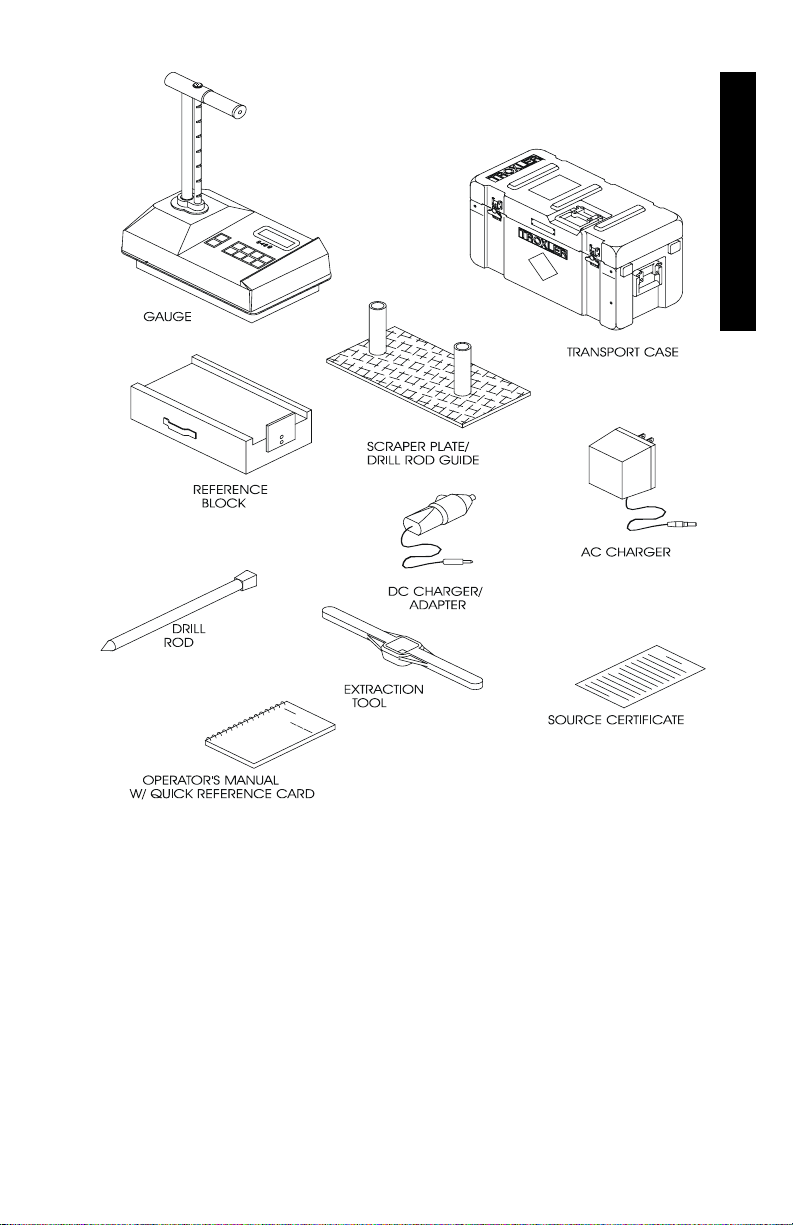
Figure 1-1 shows the Model 3430 gauge and its accessories. Use
this figure and the list below to identify the gauge and parts as they
are unpacked.
1. The Gauge is a portable instrument containing all electronic
modules, battery packs, detectors, and radioactive sources.
2. The Reference Standard Block provides a uniform reference
material for gauge adjustment to compensate for source decay.
3. The Scraper Plate/Drill Rod Guide is used to prepare the test
site and aid in guiding the drill rod into the soil.
4. The Drill Rod is used to prepare a hole for a direct transmission
reading. Do Not Use the Source Rod For This Purpose!
5. Two Chargers/Adapters are supplied: one for DC (12 VDC)
and one for AC (115/230 VAC 50/60 Hz.)
6. The Transport Case is a container designed for transportation
of the gauge and associated parts.
7. The Extraction Tool provides a means of removing the drill
rod from the test material after use.
1-4
Page 17
INTRODUCTION
Figure 1-1. Model 3430 Gauge and Accessories
Model 3430 1-5
Page 18

UNPACKING AND INSPECTION
Upon receipt of the gauge from the factory, a complete inspection
and inventory should be performed. If the shipping case, any other
part of the container, or the gauge appears to be damaged, notify the
carrier and your Troxler Representative immediately.
For shipping to another location or back to the factory, save the box
and any packing material. For shipping instructions and regulations,
please see Appendix D.
Check to see if the following literature and components have been
included:
♦ Manual of Operation and Instruction
♦ Gauge Warranty
♦ Source Certificate
♦ 3430 Gauge
♦ Scraper Plate
♦ Drill Rod
♦ AC Battery Charger
♦ DC Charger/Adapter
♦ One handle lock with keys
Lift the gauge from the case. Inspect the gauge for damage. Check
the lock on the handle. Ensure the keys fit the lock.
1-6
Page 19

STORAGE SITE SELECTION
When deciding where to store the gauge, take into consideration the
rules governing the storage of low-level radioactive devices that are
set forth by your regulatory agency and the conditions of your gauge
license.
Ë The handle should be locked and the gauge stored in its
transport case.
Ë It is recommended that the gauge and transport case be stored at
least 15 ft (5 m) from work areas, preferably in a locked
closet/storage area in a dry location (indoors).
Ë The storage area should be marked with a radiation sign that
reads “CAUTION RADIOACTIVE MATERIALS” (can be
obtained from Troxler).
Ë The storage of a nuclear gauge in a motor vehicle is not
recommended.
INTRODUCTION
Model 3430 1-7
Page 20

NOTES
1-8
Page 21

CHAPTER 2
THEORY OF OPERATION
This chapter contains a brief description of the theory of operation
of the Model 3430 Surface Moisture-Density Gauge. The direct
transmission and backscatter modes of operation are illustrated
along with a brief explanation of the cesium-137 source, americium241:beryllium or californium-252 source, and detector geometry.
CONTENTS
Density...........................................................................................2-2
Moisture.........................................................................................2-5
OPERATION THEORY
Model 3430 2-1
Page 22

DENSITY
The Troxler Model 3430 gauge utilizes two modes of operation:
direct transmission mode (source rod extended into the material)
and backscatter mode. Figures 2-1 and 2-2 illustrate the two modes
of operation.
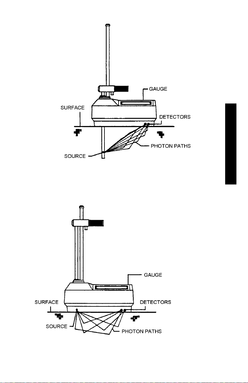
In direct transmission mode (Figure 2-1), the rod containing the
cesium-137 (8 mCi/0.3 GBq) source is lowered to the desired depth.
The detectors (G-M tubes) in the gauge base measure the radiation
emitted by the source rod. Gamma photons reaching the detectors
must first pass through the material, colliding with electrons present
in the material. In general, the lower the number of photons that
reach the detectors, the higher the material density.
In backscatter mode (Figure 2-2), the gamma photons that enter the
material must be scattered (or reflected) at least once to reach the
detectors in the gauge. With the rod locked in the first notch below
the SAFE position, the source and detectors are in the same plane,
referred to as the backscatter position. Photons emitted from the
source penetrate the material, and the detectors measure the
scattered photons. Shielding between the source and detectors
greatly reduces the number of photons reaching the detectors in a
direct path with the source.
While the direct transmission geometry measures the average
density of the material from the source to the surface, the
backscatter geometry yields an average heavily weighted by the
density close to the surface. Figure 2-3 shows two normalized top
layer effect curves, illustrating the percentages of photons at the
detectors for various depths. The two curves can be used to compute
the gauge response to layered material of different densities. For
example, the density of the top inch of a surface layer accounts for
approximately 52% of the backscatter density measurement.
2-2
Page 23
OPERATION THEORY
Figure 2-1. Direct Transmission Geometry
Figure 2-2. Backscatter Geometry
Model 3430 2-3
Page 24
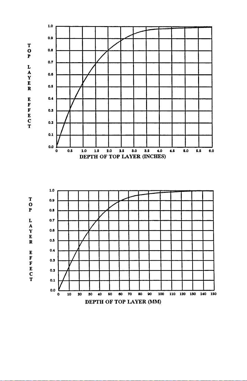
Figure 2-3. Backscatter Surface Density Effects
(Top Layer Effect Curves)
2-4 Model 3430 2-5
Page 25

MOISTURE
The Model 3430 gauge uses a 40 mCi (1.48 GBq) americium241:beryllium neutron source to measure the hydrogen content
(consequently the water content) of the material. The 3430-M gauge
employs a 60 µCi (2.22 MBq) californium-252 source.
Neutrons emitted by the Am-241:Be (or Cf-252) source penetrate
the material and are thermalized (or slowed). Thermalization is the
process where neutrons are slowed to the point where further
collisions with hydrogen or other materials will not continue to slow
the neutron.
The 3430 gauge contains a helium-3 neutron detector that is
sensitive to thermalized neutrons. This detector is insensitive to
non-thermalized, or “fast” neutrons and, as a result, the counts
obtained are directly proportional to the amount of
hydrogen/moisture present in the material.
The depth of measurement, or depth at which 98% of the counted
neutrons pass before reaching the detector, is a function of moisture
content:
Depth (inches) = 11 – (0.17
Depth (mm) = 280 - (0.27
Therefore, the higher the moisture content in the material being
measured, the smaller the depth of measurement. The normalized
curve set shown in Figure 2-4 illustrates the effect of moisture
content on the depth of measurement.
×
M), where: M = moisture in pcf
or
×
M), where: M = moisture in kg/m3
OPERATION THEORY
Page 26
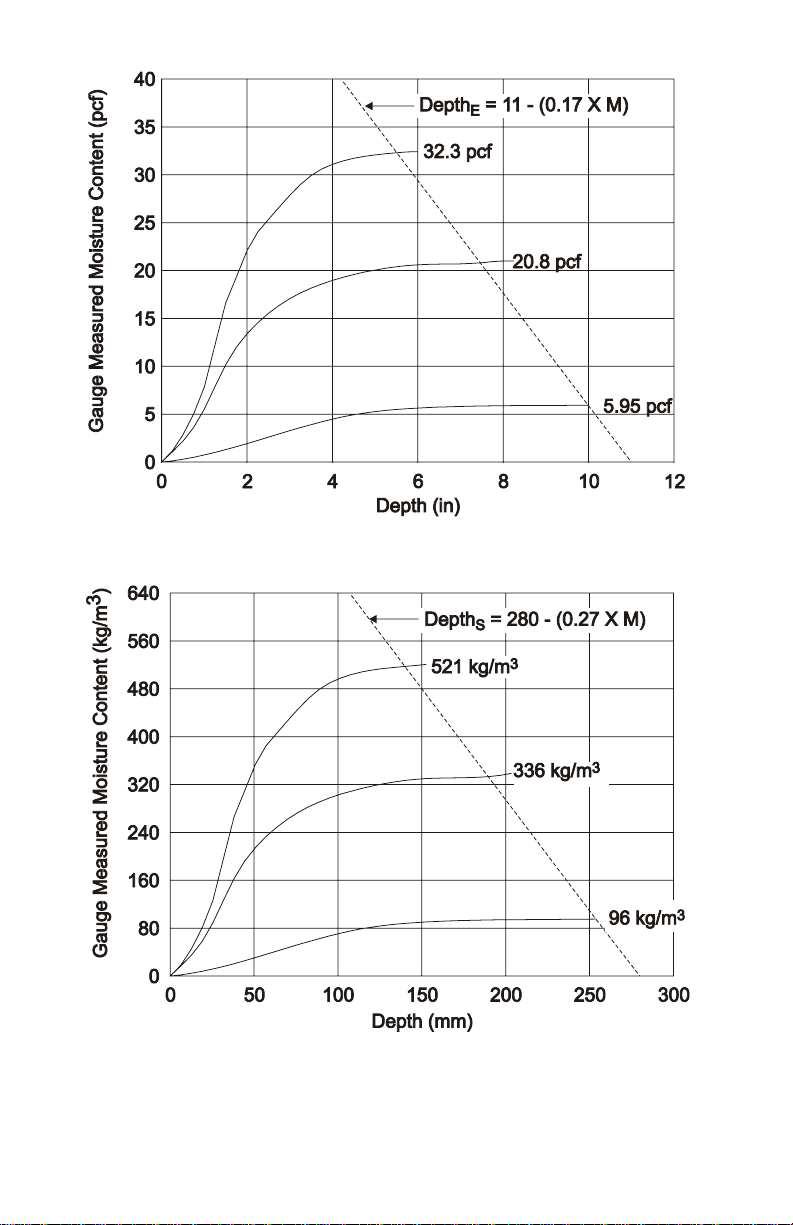
Figure 2-4. Effect of Moisture on Depth of Measurement
2-6 Model 3430 3-1
Page 27

CHAPTER 3
OPERATING THE GAUGE
This chapter explains the basic operation of the Model 3430 Surface
Moisture-Density Gauge. Instructions for conducting a daily gauge
inspection, setting gauge parameters, taking the daily standard
count, preparing the site, positioning the gauge, and taking moisture
and density measurements are included.
CONTENTS
The Keypad....................................................................................3-2
Source Rod Positions.....................................................................3-4
Daily Inspection.............................................................................3-5
Turning the Gauge On ................................................................... 3-6
Gauge Parameter Setup..................................................................3-7
Setting Measurement Units.....................................................3-7
Setting the Count Time ...........................................................3-8
Setting the Depth.....................................................................3-8
Selecting the Mode (Marshall/Proctor)...................................3-8
Taking the Standard Count..........................................................3-10
Site Preparation/Gauge Positioning.............................................3-12
Soil and Base Course Preparation.........................................3-12
Asphalt Surface Preparation..................................................3-14
Taking a Measurement – Soil Mode............................................ 3-15
Taking a Measurement – Asphalt Mode......................................3-17
GAUGE OPERATION
Page 28
THE KEYPAD
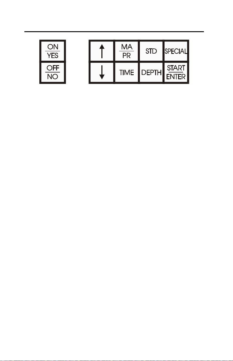
Figure 3-1. Model 3430 Keypad
The keypad (Figure 3-1) of the Model 3430 Surface MoistureDensity Gauge consists of ten keys — an eight-function keypad and
the 〈ON/YES〉 and 〈OFF/NO〉 keys. The gauge is equipped with a
beeper to verify keystrokes. If a beep is not heard when a key is
pressed, the keystroke was not recognized and should be repeated.
The 〈ON/YES〉 and 〈OFF/NO〉 keys are used for responses to
specific questions displayed on the screen and to turn the gauge on
and off.
The up and down arrows allow the operator to scroll through
various function lists displayed by the gauge.
Table 3-1 provides a more detailed description of the individual
keys and the location in the manual where the functions are
described.
3-2 Model 3430 3-3
Page 29
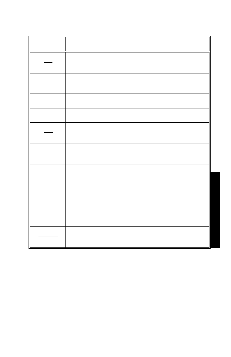
Table 3-1. Model 3430 Keypad Functions
KEYS
ON
YES
OFF
NO
↑
↓
MA
PR
TIME
STD
DEPTH
SPECIAL
DESCRIPTION PAGE
Turns on the gauge and answers Yes
to prompts.
Turns gauge off and answers No to
prompts
Scrolls the display up.
Scrolls the display down.
Allows entering or enabling of a
Proctor or Marshall value.
Allows the operator to change the
count time.
Use to access the Standard Count
mode.
Allows entry of the source rod depth. 3-8
Provides access to the Special
functions.
3-6
3-9
3-8
3-10
3-7, 4-3,
4-4, 4-7,
5-1
GAUGE OPERATION
START
ENTER
Starts a measurement or completes
answer entry.
Page 30
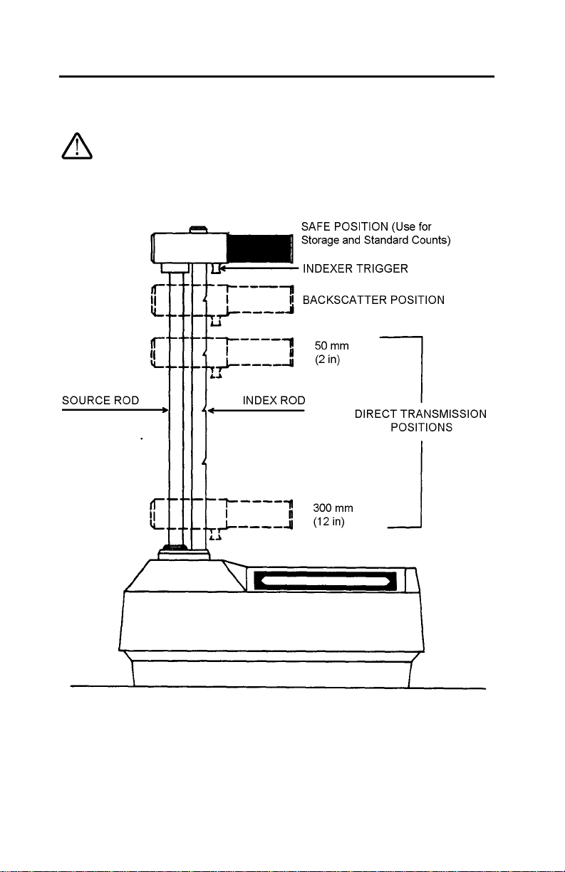
SOURCE ROD POSITIONS
Figure 3-2 shows the available positions of the source rod.
NOTE
The source rod should always be in the SAFE position
when the gauge is not in use.
3-4
Figure 3-2. Source Rod Positions
Page 31

DAILY INSPECTION DAILY INSPECTION
The gauge should be inspected daily before use to ensure proper
operation of all safety features as follows:
Push the source rod down into the backscatter position, and then
raise it back to the SAFE (shielded) position. The source rod
opening in the bottom of the gauge is equipped with a springloaded tungsten sliding block that shuts when the source rod is
in the SAFE position. Turn the gauge over and verify that the
sliding block is completely shut. If any portion of the opening is
uncovered, the sliding block should be cleaned before using,
transporting, or storing the gauge. Refer to the Mechanical
Maintenance section of Appendix C for instructions on cleaning
the tungsten sliding block.
CAUTION
Do not store or transport the gauge unless the
sliding block is completely closed. Increased
radiation levels may violate transportation
regulations and cause excessive personnel radiation
exposure.
GAUGE OPERATIONGE OPERATION
If a radiation survey instrument is available, verify that the
radioactive gamma source is in place by measuring the exposure
rate at the surface of the gauge. The exposure rate should be
approximately 10 – 20 mrem per hour. A reading of about 1
mrem or less indicates either that the survey instrument is not
working properly or that the cesium-137 source may be missing.
Refer to the Troubleshooting section of Appendix C for further
instructions.
Model 3430 3-5
Page 32

TURNING THE GAUGE ON
The gauge uses rechargeable NiCad batteries (included) as a power
source. When first turned on, the control panel displays test
characters before proceeding to the self-test.
NOTE
If the gauge turns off immediately after it is turned on,
the battery charge may be low or the gauge may be wet
inside. Refer to the information in Appendix C on
battery charging and gasket replacement.
To turn the gauge on, press 〈ON/YES〉. The gauge performs a test
of its liquid crystal display (LCD):
Testing LCD
0123456789ABCDEFG
After the 300-second self-test, the gauge will enter the Ready mode.
In this state any of the gauge functions may be accessed.
The Ready mode display is:
〈READY〉 xx min
Depth: xx inches
The first line of the display indicates the current count time. The
second line of the display indicates the source rod depth that has
been selected.
NOTE
The gauge will automatically turn off after five hours if
no keys are pressed.
3-6
Page 33

GAUGE PARAMETER SETUP
After unpacking the gauge and turning it on, there are several
parameters that can be initialized. These parameters do not usually
require changing and include the measurement units and count time.
SETTING MEASUREMENT UNITS
The 3430 gauge allows measurement results to be displayed in
either metric or US units. To set the measurement units, first access
the Special function menu by pressing 〈SPECIAL〉.
– RECALL –
(↑ ↓ or ENTER)
Press the down arrow seven times to display:
– SET UNITS –
(↑ ↓ or ENTER)
To select Set Units, press 〈START/ENTER〉.
Units: PCF
(↑ ↓ or ENTER)
Use the up and down arrows to scroll through the available units.
When the desired units are displayed, press 〈START/ENTER〉.
Model 3430 3-7
GAUGE OPERATION
Page 34

SETTING THE COUNT TIME
The count time defines how long the gauge reads. Longer count
times produce better measurement precision. Troxler recommends a
count time of one minute for most sample measurements.
To change the count time, press 〈TIME〉 to display:
Time: xx min.
(↑ ↓ or ENTER)
Use the up and down arrows to scroll through the available count
times. When the desired count time is displayed, press
〈START/ENTER〉.
SETTING THE DEPTH
To change the depth of measurement, press 〈DEPTH〉.
Depth: xx in.
(↑ ↓ or ENTER)
Use the up and down arrows to scroll through the available
measurement depths. When the desired depth is displayed, press
〈START/ENTER〉.
SELECTING THE MODE (MARSHALL/PROCTOR)
The 3430 gauge may be used on construction materials (soils,
asphalt, concrete, and so on). To select the Soil mode, enter or
activate a Proctor value. To select the Asphalt mode, enter or
activate a Marshall value. Only one Marshall and one Proctor can be
stored in the gauge at one time.
3-8
Page 35

NOTE
To measure concrete, use either the Asphalt or Soil
mode. For moisture results select the Soil mode. For
density measurement only, use the Asphalt mode.
To enter or activate a Marshall or Proctor value, press 〈MA/PR〉.
The display will be one of the following:
MA: (↑ ↓)
Change MA value?
PR: (↑ ↓)
Change PR value?
To switch from a Marshall value to a Proctor value, or vice versa,
use the arrow keys.
To activate the displayed value, press 〈OFF/NO〉.
To change the displayed value, press 〈ON/YES〉. The first digit of
the value will flash. Use the arrow keys to scroll through the
possible entries (0 – 9 and .). When the correct value for the current
digit is displayed, press 〈START/ENTER〉. The gauge will proceed
to the next digit to the right.
When the value entry is complete, the gauge activates the value and
returns to the Ready mode.
GAUGE OPERATION
Model 3430 3-9
Page 36

TAKING THE STANDARD COUNT
The 3430 gauge uses a cesium-137 and an americium-241:beryllium
source for taking measurements. These radioactive sources undergo
a natural decay process, resulting in a gradual loss in the intensity of
their radiation. The time required for the source strength to diminish
by 50% is referred to as the half-life.
To compensate for the source decay and to check proper operation
of the gauge, a daily reference standard count should be performed.
To ensure the highest accuracy possible with the gauge, it is
important to take a daily standard count.
The gauge is equipped with a reference standard block for taking the
standard count. Place the reference standard block on a dry, flat
surface at least three meters (10 ft) from any large vertical surface
and at least ten meters (33 ft) from any other radioactive source. The
surface should be asphalt, concrete or soil at least ten centimeters (4
in) thick and with a density of at least 100 pcf. The right side of the
gauge, farthest from the handle, should be against the metal butt
plate (Figure 3-3).
To begin the standard count procedure, press 〈STD〉.
DS=xxxx MS=xxxx
New Std Cnt?
To take a new standard count, press 〈ON/YES〉.
Press START for
Standard Count
Ensure that the gauge is positioned as shown in Figure 3-3. To
initiate the standard count, press 〈START/ENTER〉. After the count
is complete, the display will be:
Standard Count:
DS=xxxx MS=xxxx
3-10
Page 37

Figure 3-3. Standard Count Position
Troxler recommends that the operator keep a daily log of the
moisture and density standard counts (see Appendix E). To verify
gauge stability, compare the daily standard count to a reliable
reference as follows:
♦ During the first four days of operation of a new or recalibrated
gauge, compare the daily standard count to the factory
calibrated values.
♦ After the first four days of operation (or after taking four
standard counts), compare the daily standard count to the
average of the last four counts. Acceptable standard count limits
are:
±1% each day for DS (density standard) and
±2% each day for MS (moisture standard).
After recording the standard counts, return to the Ready mode by
pressing 〈ON/YES〉.
Model 3430 3-11
GAUGE OPERATION
Page 38

SITE PREPARATION/GAUGE POSITIONING
Preparation of the test site surface is critical to gauge performance.
This section provides site preparation procedures for both soils and
base courses and asphalt surfaces. To ensure the most accurate
gauge readings, the appropriate preparation procedure should be
followed.
SOIL AND BASE COURSE PREPARATION
Since soil surface conditions are critical to accurate
measurements, locate a level site free from any large holes,
cracks, or debris.
Smooth the surface by moving the scraper plate in a back and
forth motion. Filler such as fine sand may be used to decrease
the surface voids.
NOTE
Use only enough filler to fill the voids. Too much filler
will cause an error in the measurement.
For direct transmission measurements, put the drill rod through
the extraction tool and then through one of the guides on the
plate (see Figure 3-4).
3-12
Figure 3-4. Drill Rod Positioning
Page 39

Wearing a radiation badge and safety glasses (or other
Wearing a radiation badge and safety glasses (or other
locally approved safety devices), step on the plate and hammer
locally approved safety devices), step on the plate and hammer
the drill rod at least 50 millimeters (2 in) deeper than the desired
the drill rod at least 50 millimeters (2 in) deeper than the desired
test depth. The drill rod increments include the additional depth.
test depth. The drill rod increments include the additional depth.
Remove the drill rod by pulling straight up and twisting the
Remove the drill rod by pulling straight up and twisting the
extraction tool. Do not loosen the drill rod by tapping from
extraction tool. Do not loosen the drill rod by tapping from
side to side with a hammer. This will distort the hole or cause
side to side with a hammer. This will distort the hole or cause
loose material to fall into the hole.
loose material to fall into the hole.
To ensure accurate placement of the gauge, before removing the
To ensure accurate placement of the gauge, before removing the
scraper plate mark the test area using the drill rod as shown in
scraper plate mark the test area using the drill rod as shown in
Figure 3-5.
Figure 3-5.
Carefully pick up the scraper plate and place the gauge on the
Carefully pick up the scraper plate and place the gauge on the
surface prepared by the plate. Insert the source rod into the hole
surface prepared by the plate. Insert the source rod into the hole
made by the drill rod. Use care when inserting the source rod,
made by the drill rod. Use care when inserting the source rod,
trying not to disturb the soil around the hole.
trying not to disturb the soil around the hole.
Lower the source rod into the hole. Release the trigger and lock
Lower the source rod into the hole. Release the trigger and lock
the source rod into the correct position. A click should be heard
the source rod into the correct position. A click should be heard
when the source rod is locked into position.
when the source rod is locked into position.
Gently slide the gauge toward the keypad so the source rod
Gently slide the gauge toward the keypad so the source rod
makes contact with the wall of the hole.
makes contact with the wall of the hole.
MARK FOR SCRAPER
PLATE CENTER
EDGE
MARKS
GAUGE OPERATIONGE OPERATION
SCRAPER
PLATE
METHOD 1
MARK FOR DRILL
ROD CENTER
SCRAPER
PLATE
METHOD 2
Figure 3-5. Marking the Test Area Figure 3-5. Marking the Test Area
Model 3430 3-13
Page 40

ASPHALT SURFACE PREPARATION
It is possible, but usually not necessary, to take direct transmission
readings on asphalt. Drilling a hole in asphalt can be difficult, and
may require the use of a drill (rather than the drill rod) if the asphalt
has cooled and hardened.
Under normal conditions, a backscatter reading provides an accurate
measurement of asphalt density.
Find a smooth, level location on the asphalt. The operator may
want to fill the voids on open mixes with sand or cement. Take
care to leave the asphalt exposed. The gauge base must rest on
the asphalt, not the fill material!
Ensure that the gauge does not “rock.” It must remain steady. If
rocking occurs, find a more suitable test site. If taking a
measurement around a core, the gauge may be moved a few
inches away from the hole to level the gauge.
3-14
Page 41

TAKING A MEASUREMENT – SOIL MODE TAKING A MEASUREMENT – SOIL MODE
The Soil mode is automatically selected when a Proctor value is
enabled (see page 3-8).
NOTE
When not taking measurements, always keep the
source rod in the SAFE position. For added operator
safety, the source rod on the 3430 gauge automatically
retracts to the SAFE position when the gauge is lifted
by the handle.
If you do not hear a click when the source rod is raised to the SAFE
position, look at the bottom of the gauge to verify that the tungsten
sliding block is completely closed. If the gauge base opening is not
completely closed by the sliding block, the sliding block may
require cleaning. Refer to Appendix C for cleaning instructions.
CAUTION
Do not store or transport the gauge unless the
tungsten sliding block is completely closed.
Increased radiation levels may violate transportation
regulations and cause excessive personnel exposure.
GAUGE OPERATIONGE OPERATION
Place the gauge over the test site. Release the gauge handle and
push it down until it is in the correct position. Ensure that the pin
engages the notch in the index rod.
Press 〈START/ENTER〉.
Depth: xx in.
Time: xxx sec.
After the count time has elapsed, the gauge displays the
measurement results in a series of six screens, as follows. Use the
up and down arrows to scroll through the various screens.
Model 3430 3-15
Page 42

WD: xxxxx PCF
(Use ↑ & ↓ keys)
DD: xxxxx PCF
%PR: xx.x %
Moist: xxxxx PCF
% Moist: xx.x %
Air Void: xx.x%
Void Ratio
MOIST CR: xx.x
DENS CR: xx.x
3-16
M Count: xxxxx
D Count: xxxxx
where:
WD = Wet density in kg/m
DD = Dry density in kg/m
%PR = Percent Proctor (This value is valid only if an
appropriate target has been entered for the material
being tested.)
MOIST = Moisture value in kg/m
% MOIST = Percent moisture
Air Void = See description below
Void Ratio = See description below
MOIST CR = Moisture count ratio
DENS. CR = Density count ratio
M Count = Moisture counts as read by the gauge
D Count = Density counts as read by the gauge
3
or pcf
3
or pcf
3
or pcf
Page 43

Figure 3-6 illustrates the terms void ratio and % air voids. The void
ratio is the ratio of the volume occupied by air and water in the soil
to the volume occupied by solid particles. The term % air voids
refers to the volume of air voids only as a percentage of the total
volume.
The following formulas are used to calculate the % air voids and
void ratio values.
% AIR VOIDS = 100 (1 – (Vs/Vt) – (Vw/Vt))
where:
Vs = Volume of Soil
Vt = Total Volume
Vw = Volume of Water
or,
% AIR VOIDS = 100 (1 – (DD / SG(Dw)) – (M / (Dw)))
where:
Dw = Density of Water
SG = Specific Gravity of Soil Particles
DD = Dry Density
M = Moisture
VOID RATIO = Volume of Voids / Volume of Soil
= ( SG(Dw) – DD ) / DD
GAUGE OPERATION
Figure 3-6. Voids Illustration
Model 3430 3-17
Page 44

TAKING A MEASUREMENT – ASPHALT MODE
The Asphalt mode is automatically selected when a Marshall value
is enabled (see page 3-8).
NOTE
When not taking measurements, always keep the
source rod in the SAFE position. For added operator
safety, the source rod on the 3430 gauge automatically
retracts to the SAFE position when the gauge is picked
up by the handle.
If you do not hear a click when the source rod is raised to the SAFE
position, look at the bottom of the gauge to verify that the tungsten
sliding block is completely closed. If the gauge base opening is not
completely closed by the sliding block, the sliding block may
require cleaning. Refer to Appendix C for cleaning instructions.
CAUTION
Do not store or transport the gauge unless the
tungsten sliding block is completely closed.
Increased radiation levels may violate transportation
regulations, and may cause personnel exposure.
Place the gauge over the test site. Release the gauge handle and
push it into the backscatter position. Set the depth to Backscatter.
Ensure that the pin engages the notch in the index rod. Gently tap
the handle down to ensure proper source rod seating.
Press 〈START/ENTER〉.
Depth: BACKSCAT.
Time: xxx sec.
After the count time has elapsed, the gauge displays the
measurement results in a series of six screens, as follows. Use the
up and down arrows to scroll through the various screens.
3-18
Page 45

WD: xxxxx PCF
% MA xx.x %
DD: xxxxx PCF
(Use ↑ & ↓ keys)
Moist: xxxxx PCF
% Moist: xx.x %
% VOIDS xx.x %
100 – % MA xx.x %
MOIST CR: xx.x
DENS CR: xx.x
M Count: xxxxx
GAUGE OPERATION
D Count: xxxxx
where:
WD = Wet density in kg/m
3
or pcf
% MA = Percent Marshall (This value is valid only if an
appropriate target has been entered for the material
being tested.)
DD = Dry density in kg/m
MOIST = Moisture value in kg/m
3
or pcf
3
or pcf
% MOIST = Percent moisture
% VOIDS = 100 (1 – WD/VOIDLESS)
100 – % MA = Value given by subtracting the percent
Marshall value from 100
MOIST CR = Moisture count ratio
DENS. CR = Density count ratio
M Count = Moisture counts as read by the gauge
D Count = Density counts as read by the gauge
Model 3430 3-19
Page 46

NOTES
3-20
Page 47

CHAPTER 4
ADVANCED GAUGE OPERATION
This chapter provides instructions for using the Model 3430 Surface
Moisture-Density Gauge in special circumstances where the gauge
may require an offset or special calibration. This chapter also
explains the procedure for using the gauge to measure thin layers of
asphalt.
CONTENTS
Offsets............................................................................................4-2
Density Offset .........................................................................4-3
Moisture Offset .......................................................................4-4
Trench Offsets.........................................................................4-6
Special Calibrations.......................................................................4-7
Entering a New B Value..........................................................4-8
Gauge-calculated Calibration..................................................4-9
Thin Layer Measurements...........................................................4-11
Model 3430 4-1
ADVANCED OPERATION
Page 48

OFFSETS
The Model 3430 is factory-calibrated for soils, asphalt, and concrete
with an approximate density range of 1100 to 2700 kg/m
pcf). With an offset, the operator can adjust the gauge readings to
correlate to traditional laboratory methods, such as core samples.
The 3430 gauge provides three offsets: density, moisture, and
trench.
NOTE
When an offset has been enabled, all future readings will
automatically be adjusted with the offset factor
regardless of the test site. It is very important that the
operator disable the offset function prior to taking
readings on materials that do not require an offset
Offsets are disabled if the gauge is turned off for more
than 10 seconds.
Density offsets are common when the material being measured is
outside the range of 70 to 170 pcf (1121 to 2723 kg/m
material composition varies from average soil/asphalt on which the
factory calibration is based.
Moisture offsets are required for accurate measurements if the
material to be measured contains elements that can cause the gauge
to yield erroneous results. A negative offset is required if the
material to be measured is high in hydrogenous components such as
cement, gypsum, coal, or lime. A positive offset is required if the
material is high in neutron-absorbing material such as boron or
cadmium.
The 3430 gauge requires an offset if measurements are to be taken
inside a trench or close to vertical structures. Vertical structures can
scatter neutrons and gamma photons back to the gauge, increasing
the possibility of moisture or density errors due to high counts.
3
(70 to 170
.
3
) or if the
4-2
Page 49

DENSITY OFFSET
To access the Special functions, press 〈SPECIAL〉.
Press the down arrow key once to access the Offset function. Press
〈START/ENTER〉 to display:
Offset: Density
(↑ ↓ or ENTER)
Press 〈START/ENTER〉.
Dens. Offset OFF
Want to Enable?
To enable the Density Offset function, press 〈ON/YES〉.
D off= 0.0 PCF
(↑ ↓ or ENTER)
Input the difference between the gauge and actual density readings.
To input a minus sign (for a negative offset), press the down arrow
first. To scroll through the numerals, press up and down arrows.
To select the next digit and/or exit, press 〈START/ENTER〉.
The display will be:
Dens. Offset ON
Model 3430 4-3
ADVANCED OPERATION
Page 50

MOISTURE OFFSET
Some soils contain hydrogen sources other than water and/or
neutron absorbers. Since the 3430 gauge measures moisture by
determining the hydrogen content of the material and relating this to
the water content, both types of material could cause gauge readings
that differ from the true moisture. If measuring such materials, use a
moisture offset to adjust the readings.
The offset factor (k) is determined by comparing the moisture
content of a laboratory sample with the moisture content determined
by a gauge reading. To determine the offset factor, use the following
procedure:
Take a gauge reading at the site. Record the reading (%M
Remove a sample from the measurement site, then use
laboratory methods methods (for example, oven dry, and so on)
to determine the moisture content of the sample (%M
LAB
Multiple samples and measurements may be taken. Calculate
the average moisture of the samples. This average value should
be used for the offset factor calculation.
Calculate the offset factor (k).
k =
%M
100 + %M
LAB
– %M
GAUGE
GAUGE
×
1000
NOTE
If the k value is negative, a minus sign (–) must be
entered by pressing the down arrow before entering the
first digit.
To access the Special functions, press 〈SPECIAL〉.
GAUGE
).
).
4-4
Page 51

Press the down arrow key once to access the Offset function. Press
〈START/ENTER〉 to display:
Offset: Density
(↑ ↓ or ENTER)
To enter a moisture offset, press the down arrow once and press
〈START/ENTER〉.
Moist Offset OFF
Want to enable?
To enable the Moisture Offset function, press 〈ON/YES〉.
K= 0.0
(↑ ↓ or ENTER)
The first digit will flash. To input a minus (–) sign (for a negative
offset), press the down arrow first
values for each digit, press the arrow key. To select the next digit,
press 〈START/ENTER〉. When all digits are entered, the gauge will
enable the offset. The display will be:
! To scroll through the possible
Moist Offset ON
Model 3430 4-5
ADVANCED OPERATION
Page 52

TRENCH OFFSETS
If the Model 3430 gauge is to be used for moisture or density
measurements in a trench or within two feet (0.6 m) of a large
vertical structure, a trench offset may be required. If used, the trench
offset adjusts all moisture measurements but only the density
measurements from backscatter through four inches (10 cm).
To perform a trench offset:
Take the daily standard count (outside the trench) and record the
density count (DS) and moisture count (MS)values.
Place the gauge on the reference standard block in the trench the
same distance from the wall as the anticipated readings. Do not
take another standard count.
Set the count time to four minutes.
With the source rod in the SAFE (standard count) position, take
a four-minute count. To start the count, press the
〈START/ENTER〉 key.
Record the trench density count (DC
(MC
Trench
.).
Subtract the daily standard count values from the trench count
values:
Dens Const = (DC
Trench
) – DS
) and moisture count
Trench
Moist Const = (MC
Trench
) – MS
To enable a trench offset, choose Trench from the Offset options
under the Special functions. The gauge requests the Dens Const and
Moist Const values determined above. The procedure for entering
the values is the same as for moisture and density offsets, ignoring
the ± sign on the display.
4-6
Page 53

SPECIAL CALIBRATIONS
Troxler gauges are calibrated to “average soil.” Average soil is
defined as material consisting of 50% limestone (calcareous) and
50% granite (siliceous). This factory calibration provides accurate
results for the majority of materials encountered in the field.
However, there are situations when varying material compositions
could affect the gauge accuracy. In these special cases the gauge B
value can be recalculated either by the gauge or by considering the
mass attenuation (µ/ρ) of the material.
If the chemical composition of the soil is known, Troxler can
provide a procedure for recalculating the B value for manual entry
(see page 4-8) to accurately measure the soil density. This
calculation requires in-depth knowledge of the gauge geometry and
the detected energy spectrum of the Cs-137 source.
The Special Calibration function allows the Model 3430 gauge to
be recalibrated for material densities and compositions other than
those covered by the factory calibration.
The true density of a sample of the material must be obtained prior
to calculating a special calibration. This density may be obtained
from a laboratory sample.
To access the Special functions, press 〈SPECIAL〉.
To access the Special Calibration function, press the down arrow
four times. Press 〈START/ENTER〉 to display:
SPECIAL CALIB.
Want to Recalib?
ADVANCED OPERATION
Model 3430 4-7
Page 54

To recalibrate the gauge for the densities outside the factory
calibration range, press 〈ON/YES〉. To disable the Special
Calibration feature, press 〈OFF/NO〉 at the above display and
〈ON/YES〉 at the disable inquiry. After disabling this feature, the
gauge will return to the Ready mode.
SPECIAL CALIB.
Enter B Value?
To enter a known B value obtained with the procedure available
from Troxler, press 〈ON/YES〉. To have the gauge calculate the
recalibration, press 〈OFF/NO〉. If entering a new known B value,
see the following explanation. For gauge-calculated special
calibration, see page 4-9.
ENTERING A NEW B VALUE
Depth = xx in
(↑ ↓ or ENTER)
To change the value of the flashing digit for the measurement depth,
use the up and down arrows. To accept the flashing value and select
the next digit, press 〈START/ENTER〉.
B VAL = x.xxxx
(↑ ↓ or ENTER)
The gauge displays the current B value. To change the value of the
flashing digit, use the up and down arrows. To accept the flashing
digit and select the next digit, press 〈START/ENTER〉.
4-8
Page 55

Upon entry completion, the gauge will indicate that the special
calibration is enabled and return to the Ready mode. Note that when
the gauge is turned off the Special Calibration is disabled.
SPECIAL CALIB.
ENABLED!
GAUGE-CALCULATED CALIBRATION
The true density of the sample and a gauge reading must be
performed on the material for the special calibration routine to
adjust the gauge calibration.
NOTE
When using destructive methods such as drilling cores
or sample removal for true density measurement, take
gauge readings before removing samples.
To select the depth and/or exit, press 〈START/ENTER〉.
Depth: xx in.
(↑ ↓ or ENTER)
To scroll through the numerals for the depth of the measurement,
press the up and down keys. To select the next field and/or exit,
press 〈START/ENTER〉.
If calibration counts have not been taken, the gauge will take four
one-minute counts.
The gauge provides the operator with a partial calibration feature.
Since a partial calibration allows the operator to enter the density
after taking counts, it is helpful to those performing destructive
material testing. If the operator has previously taken calibration
counts, the gauge asks if these counts should be used in calibrating
the gauge. To use the previous counts, press 〈ON/YES〉. The gauge
will then request the density. To take new counts, press 〈OFF/NO〉.
Model 3430 4-9
ADVANCED OPERATION
Page 56

Press START for
Reading # x
Place the gauge on the test material. To begin taking the four oneminute counts, press 〈START/ENTER〉. After each count is
complete, the operator must initiate the next count by pressing
〈START/ENTER〉.
Enter known
density now?
To create a partial calibration and return to the Ready mode, press
〈OFF/NO〉. To complete the special calibration by entering the
density, press 〈ON/YES〉.
Density: xx
(↑ ↓ or ENTER)
To change the value of a digit, press the up and down arrows. To
select the next digit, press 〈START/ENTER〉. After the density
value is entered, the special calibration routine readjusts the gauge
for the new material and indicates that the special calibration is
enabled. The special calibration is only valid for the depth selected
during the special calibration.
SPECIAL CALIB.
ENABLED!
4-10
Page 57

THIN LAYER MEASUREMENTS
With the increase in thin lift overlay applications and the limitations
of conventional backscatter gauges to measure these overlays the
following method (formula) has been developed:
DT =
where:
DT = Overlay density
WD = Density read by gauge
DB = Bottom layer density
K = Effect of top layer thickness on the gauge
To use the above method of overlay measurement, follow the
procedure below:
Determine the density of the bottom layer (underlying material)
(DB).
Apply the thin lift overlay.
Determine the thickness of the overlay and select the
corresponding (k) value from Table 4-1.
Measure the thin lift overlay density with the gauge in
backscatter position (WD).
Enter all values into the above equation and calculate the
overlay density (DT).
WD – DB
1 – K
×
K
ADVANCED OPERATION
Model 3430 4-11
Page 58

EXAMPLE
Given the following values:
Bottom Density (DB) = 135 pcf (2162 kg/m
Overlay Thickness = 1.2 inches (30 mm)
K (from Table 4-1) = 0.38235
Density read by gauge (WD) = 142.0 pcf (2275 kg/m
×
DT =
142.0 – (135
1 – 0.38235
0.38235)
DT = 146.3 pcf
or,
DT =
2275 – (2162
1 – 0.38235
DT = 2345 kg/m
×
0.38235)
3
NOTE
The majority of the backscattered gamma rays reaching
the detectors are the result of interactions in the top 3.3
inches (84 mm) of the overlay. In applications where the
overlay thickness is greater than 3.3 inches (84 mm), use
(0) for the k value or use the actual gauge readings
(WD).
3
)
3
)
4-12
Page 59

Table 4-1. K Values for Thin Lift Overlays
Thickness
(inches)
1.0 25 0.46159 55 0.13459
26 0.44787 2.2 56 0.12880
27 0.43414 57 0.12078
1.1 28 0.42042 2.3 58 0.11275
29 0.40138 59 0.10781
1.2 30 0.38235 60 0.10285
31 0.36475 2.4 61 0.09790
32 0.35889 62 0.09104
1.3 33 0.34716 2.5 63 0.08418
34 0.33631 64 0.07995
35 0.32547 65 0.07572
1.4 36 0.31462 2.6 66 0.07149
37 0.29958 67 0.06562
1.5 38 0.28454 2.7 68 0.05976
39 0.27527 69 0.05615
40 0.26600 70 0.05253
1.6 41 0.25673 2.8 71 0.04892
42 0.24387 72 0.04390
1.7 43 0.23102 2.9 73 0.03889
44 0.22310 74 0.03580
45 0.21517 75 0.03271
1.8 46 0.20725 3.0 76 0.02962
47 0.19626 77 0.02676
1.9 48 0.18527 78 0.02391
49 0.17850 3.1 79 0.02105
50 0.17172 80 0.01709
2.0 51 0.16495 3.2 81 0.01313
52 0.15556 82 0.01069
2.1 53 0.14617 83 0.00825
54 0.14038 3.3 84 0.00581
Thickness
(mm)
K
Thickness
(inches)
Thickness
(mm)
K
ADVANCED OPERATION
Model 3430 4-13
Page 60

NOTES
4-14
Page 61

CHAPTER 5
SPECIAL FUNCTIONS
This chapter gives brief explanations of the Special functions
available on the Model 3430 Surface Moisture-Density Gauge, or
directs the reader to the appropriate section dealing with a particular
function.
CONTENTS
Recall.............................................................................................5-2
Offset .............................................................................................5-2
Stat Test.........................................................................................5-2
Drift Test........................................................................................5-5
SPECIAL FUNCTIONS
Special Calibration.........................................................................5-7
Specific Gravity.............................................................................5-7
Voidless Density............................................................................5-8
Set Units.........................................................................................5-8
Calibration Constants.....................................................................5-9
Memory Reset..............................................................................5-10
Test Reading................................................................................5-10
Language......................................................................................5-11
15-second Inhibit.........................................................................5-12
Model 3430 5-1
Page 62

RECALL
The Recall function allows the operator to view the data from the
last reading. Even though the 3430 gauge does not store multiple
readings, this function displays the latest data.
To access the Special functions, press 〈SPECIAL〉.
To access the Recall feature, press 〈START/ENTER〉.
The gauge displays the data from the last measurement. Scroll
through the screens using the up and down arrow keys.
OFFSET
For information on offsetting gauge readings, refer to Chapter 4.
STAT TEST
The statistical stability test, or stat test, may be performed to
validate the normal operation of the gauge. Erratic readings or
readings that seem to fluctuate may indicate a problem with the
gauge. In the event the readings are suspect, a stat test may be
executed.
A stat test consists of twenty 1-minute counts. After the twenty
counts, the gauge calculates the standard deviation. This standard
deviation is compared to a theoretical standard deviation value.
Ideally this ratio should be one. However, the 3430 gauge pre-scales
(or divides) the counts by 16, resulting in an ideal ratio of 0.25. The
acceptable limits for the ratio are from 0.17 to 0.33. The gauge is
considered to be unstable if the ratio is outside these limits.
5-2
Page 63

To perform a stat test on the 3430 gauge, place the gauge on the
reference standard block in the standard count position (see
Chapter 3).
To access the Special functions, press 〈SPECIAL〉.
To access the Stat Test feature, press the down arrow twice and
press 〈START/ENTER〉.
press START for
20 min Stat Test
To begin the twenty counts, press 〈START/ENTER〉.
The gauge will display the stat test count progress as shown below.
– STAT TEST –
Rdg.#:xx xx sec
Upon completion of the stat test, the gauge displays the pass/fail
status. If the stat test fails, repeat the test twice more. If two out of
three stat tests fail, contact Troxler. If the stat test passes, the display
is:
SPECIAL FUNCTIONS
D: PASS M: PASS
↑ ↓ to view data
To view the stat test data, use the up and down arrow keys.
Dens. R = xxxx
↑ ↓ to view data
Dens. Avg. xxxx
↑ ↓ to view data
Model 3430 5-3
Page 64

Moist R = xxxx
↑ ↓ to view data
Moist Avg. xxxx
↑ ↓ to view data
•
•
•
#20 D xxxx M xxxx
(Use ↑ & ↓ keys)
5-4
Page 65

DRIFT TEST
If the stat test has already been performed (and passed), but gauge
readings seem to drift between tests, the drift test can check the
long-term drift of the 3430 gauge.
A drift test consists of five 4-minute counts taken approximately 3
to 8 hours after completion of a stat test with no movement of the
gauge between tests. Pass/fail limits are set using the percent
difference between the average of the stat and drift test results. If the
percent difference exceeds 0.5% for density or 1% for moisture, the
drift test fails.
The gauge should not be turned off between the stat test
and drift test. The stat test must be current.
In addition, the gauge must not be moved between the
stat and drift tests to eliminate possible failure due to
positioning changes.
With the gauge still in the standard count position (on the reference
standard block), press 〈SPECIAL〉.
From the Special functions, select the Drift Test feature by pressing
the down arrow three times and 〈START/ENTER〉.
NOTE
SPECIAL FUNCTIONS
press START for
20 min Drift Test
To begin the five counts, press 〈START/ENTER〉.
– DRIFT TEST –
Rdg.#:xx xxx sec
As with the stat test, the gauge indicates the count progress during
the drift test.
Model 3430 5-5
Page 66

After the five counts have been completed, the display is:
D: PASS M: PASS
↑ ↓ to view data
To view the stat test data, use the up and down arrow keys.
D% Drift xxxx
↑ ↓ to view data
Dens. Avg. xxxx
↑ ↓ to view data
M% Drift xxxx
↑ ↓ to view data
•
•
•
5-6
#5 D xxxx M xxxx
(Use ↑ and ↓ keys)
Page 67

SPECIAL CALIBRATION
For information on performing a special calibration, see Chapter 4.
SPECIFIC GRAVITY
The specific gravity of a solid is defined as the density of the
material divided by the density of water. The Specific Gravity
function allows the operator to input the specific gravity of a
material into the gauge. This value (SG) is used in the calculation of
% Air Voids and Void Ratio (see Chapter 3).
To access the Special functions, press 〈SPECIAL〉.
To access the Specific Gravity feature, press the down arrow five
times and press 〈START/ENTER〉.
SG = 2.70
(↑ ↓ or ENTER)
To change the value of the flashing digit, use the up and down
arrows. To accept the flashing value and select the next digit, press
〈START/ENTER〉.
If a value is not entered, the default value is the specific gravity for
soil grains (2.70).
SPECIAL FUNCTIONS
Model 3430 5-7
Page 68

VOIDLESS DENSITY
The Voidless Density function allows the input of the theoretical
voidless density value of the material being measured. This value is
used in the % Voids calculation.
To access the Special functions, press 〈SPECIAL〉.
To access the Voidless Density feature, press the down arrow six
times and press 〈START/ENTER〉.
VD = xxx.x
(↑ ↓ or ENTER)
To change the value of the flashing digit, use the up and down
arrows. To accept the flashing value and select the next digit, press
〈START/ENTER〉.
SET UNITS
For information on the Set Units feature, see Chapter 3.
5-8
Page 69

CALIBRATION CONSTANTS
The Calibration Constants function allows the operator to change
the mathematical constants used for calculating a test result. If the
gauge has been repaired or the memory has been lost, the constants
must be verified or re-entered.
NOTE
Each 3430 gauge contains a unique set of constants. The
constants used in one gauge will not work in another
gauge! The constants for your 3430 gauge are developed
at the factory and are reflected on the factory
calibration sheet.
To access the Special functions, press 〈SPECIAL〉.
To access the Calibration Constants feature, press the down arrow
key eight times and press 〈START/ENTER〉.
Enter code –
0
This feature requires the input of the access code found in the front
of this manual. Using the up and down arrow keys to select the
correct number for the flashing digit, enter the access code. To
accept the flashing value and select the next digit, press
〈START/ENTER〉.
The gauge will prompt for the input of the E value.
NOTE
If the value is negative, enter a minus sign (–) by
pressing the down arrow key prior to entering the first
digit. Leading zeros must be entered (for example:
0.012345).
To change the value of the flashing digit for the E value, use the up
and down arrows. To accept the flashing value and select the next
digit, press 〈START/ENTER〉.
SPECIAL FUNCTIONS
Model 3430 5-9
Page 70

Enter the remaining constants for each depth.
NOTE
If the calibration sheet lists B and F values, instead of
B*1000 and F*1000 values, then the calibration is in
English, rather than metric, units. Therefore, the B and
F values must be converted to metric values and
multiplied by 1000 before they are entered into the
gauge. A more direct method is to multiply the B and F
values by 62.4298, then enter the resulting products into
the gauge.
MEMORY RESET
This function is for authorized service personnel only!
NOTE
CAUTION
Memory Reset erases all data stored in the gauge and
sets all constants, except calibration constants, to the
default values.
TEST READING
This function is for authorized service personnel only!
5-10
NOTE
Page 71

LANGUAGE
The 3430 gauge supports three language displays (English, French,
and Spanish). Troxler also offers keypad inserts in each of these
three languages (see Appendix C).
To change the display language, first access the Special functions by
pressing 〈SPECIAL〉. Press the up arrow once.
– LANGUAGE –
(↑ ↓ Or ENTER)
To access the Language feature, press 〈START/ENTER〉.
Enter code –
0
To prevent unauthorized language changes, this feature requires the
input of the access code found in the front of this manual. Using the
up and down arrow keys to select the correct number for the
flashing digit, enter the access code. To accept the flashing value
and select the next digit, press 〈START/ENTER〉.
SPECIAL FUNCTIONS
English
(↑ ↓ Or ENTER)
To display all gauge operations in English, press
〈START/ENTER〉. The gauge returns to the Ready mode.
To access either of the other two languages, use the arrow keys.
When the desired language is displayed, press 〈START/ENTER〉.
The gauge returns to the Ready mode.
Model 3430 5-11
Page 72

15-SECOND INHIBIT
The 15-second Inhibit function enables the gauge owner or operator
to disable the 15-second count option. When this function is
enabled, the 3430 gauge can only conduct one- or four-minute
counts.
To disable the 15-second count option, first access the Special
functions by pressing 〈SPECIAL〉. Use the up or down arrows to
display:
– 15 SECONDS –
(↑ ↓ Or ENTER)
To access the 15-second Inhibit function, press 〈START/ENTER〉.
Enter Code –
0
This feature requires the input of the access code found in the front
of this manual. Using the up and down arrow keys to select the
correct number for the flashing digit, enter the access code. To
accept the flashing value and select the next digit, press
〈START/ENTER〉.
If the 15-second count option is currently enabled, the gauge
displays:
– 15 SECONDS –
Want to DISABLE?
Press 〈ON/YES〉 to disable the 15-second count option. The
gauge returns to the Ready mode.
If the 15-second count option is currently disabled, the gauge
displays:
– 15 SECONDS –
Want to ENABLE?
Press 〈ON/YES〉 to enable the 15-second count option. The
gauge returns to the Ready mode.
5-12
Page 73

APPENDIX A
RADIATION THEORY AND SAFETY
This appendix is required reading for anyone who will operate the
Model 3430 Surface Moisture-Density Gauge. This information
covers radiation theory, along with a brief explanation of radiation
statistics and radiation terminology.
CONTENTS
Radiation Theory .......................................................................... A-2
Atomic Structure.................................................................... A-2
Radiation Terminology ..........................................................A-3
Radiation Theory.................................................................... A-3
Radiation Statistics.................................................................A-4
Radiation Safety............................................................................A-5
Types of Radiation................................................................. A-5
Limiting Exposure.................................................................. A-5
Monitoring Radiation.............................................................A-7
3430 Radiation Profile ...........................................................A-8
Source Encapsulation...........................................................A-11
Emergency Procedures......................................................... A-12
RADIATION THEORY
Model 3430 A-1
Page 74

N
RADIATION THEORY
A more detailed discussion of radiological theory can be found in
the Troxler Nuclear Gauge Safety Training Program manual,
provided at the Troxler safety class.
ATOMIC STRUCTURE
All materials consist of chemical elements that can not decompose
by ordinary chemical methods. Some examples are:
(H) Hydrogen (C) Carbon (O) Oxygen
(U) Uranium (Cf) Californium (Co) Cobalt
Each element contains an atom with a unique structure. The atom
consists of protons, neutrons, and electrons (Figure A-1). The
protons and neutrons are grouped together in the nucleus. The
electrons orbit the nucleus. An atom is normally electrically neutral
because the positive charge of the protons cancels out the negative
charge of the electrons.
ELECTRONS
NEUTRON
PROTO
Figure A-1. Diagram of an Atom
Protons carry a positive charge and are described as having a mass
of one. Neutrons have no charge and also have a mass of one.
Electrons carry a negative charge and essentially have no mass.
MASS
(ATOMIC WEIGHT SCALE)
Protons 1.0073 +1
Neutrons 1.0087 0
Electrons 0.0006 –1
CHARGE
A-2 Model 3430 A-3
Page 75

Since protons and neutrons are clustered together in the nucleus, the
mass of an atom is concentrated in the nucleus. The atom shown in
Figure A-1 has two protons and two neutrons; therefore, it is a
helium atom. The atomic weight of an atom is the sum of the
number of protons and the number of neutrons.
RADIATION TERMINOLOGY
The curie, defined as the quantity of radioactive material giving 3.7
10
× 10
disintegrations per second, is equal to the number of
disintegrations/second of one gram of radium-226. Note that the
source used in the 3430 is small, with quantities expressed in
millicurie (mCi). The SI unit of radiation is the becquerel (Bq). A
becquerel equals one disintegration per second. Therefore, one curie
equals 3.7 × 10
10
Bq.
The rad, or radiation absorbed dose, is the unit of absorbed dose
equal to 0.01 joules/kg in any medium. To account for the effect of
various types of radiation on biological tissue, the roentgen
equivalent man (rem), or, more appropriate for Troxler operators,
the millirem is used when measuring radiation dose. The unit rem is
derived by multiplying the radiation absorbed dose (rad) by a
quality factor (QF). One rad is equal to the exposure of one rem of
photon radiation. For example, the average neutron energy of an
americium-241:beryllium source is approximately 4.5 MeV. The
quality factor (QF) for this radiation is about 10. The absorbed dose
of 1 rad of neutron radiation gives a dose equivalent (absorbed dose
× QF) of 10 rem (0.1 Sv).
RADIATION THEORY
Radioactivity is the spontaneous breakdown of unstable nuclei
(radioisotopes) with the resulting emission of radiation. The strength
of radioactive material is measured by its activity, or rate of decay.
This activity decreases with time. The length of time it takes a given
amount of radioactive material to decay to half of its original
strength is referred to as the half-life. The half-life of cesium-137 is
30 years, while that of americium-241 is 432 years. Californium252 has a half-life of 2.6 years.
RADIATION THEORY
Page 76

σ-1σ
σ2σ
RADIATION STATISTICS
Radioactive emission is a random process. The number of emissions
in a given time period is not constant but varies statistically about an
average value. The variation about the true mean value is a Poisson
distribution. In this distribution, the standard deviation (
mean (n) is defined as:
σ
= √n
When the mean is greater than 100, the Poisson distribution can be
closely approximated by the normal distribution (Figure A-2). The
normal distribution predicts the probability that any given count rate
will fall within a selected region about the mean.
Normal Distribution
σ
) about the
σ
-3
-2
MEAN
68.3%
95.4%
99.7%
σ
1
3
Figure A-2. Variation of Radioactive Emission
Using the average of a large number of counts to approximate the
true mean, the distribution shows that 68.3% of the time the count
rate obtained will be within ±1 standard deviation of the mean.
Figure A-2 shows the probability of counts falling within three
standard deviations of the mean. The operator may perform a
statistical stability test (stat test) to compare the experimental
standard deviation to the theoretical standard deviation (see
Chapter 5).
A-4 Model 3430 A-5
Page 77

RADIATION SAFETY
This section provides a brief discussion of general radiation safety.
The exposure profile for the Model 3430 gauge is also included,
along with a discussion of the source encapsulation.
TYPES OF RADIATION
The radioactive sources in the Model 3430 produce four types of
radiation:
Alpha Particles
Beta Particles
Photons (Gamma Rays)
Neutrons
The alpha and beta particles are stopped by the source capsule. Only
the photons and neutrons contribute to any occupational radiation
exposure.
Photon (gamma) radiation is electromagnetic radiation, as are xrays, radio waves, and visible light. Photons have no mass, no
electrical charge, and travel at the speed of light. Photons are
energetic and penetrating. Dense materials (such as lead, tungsten,
and so on) provide the best shielding against photon radiation.
Neutron radiation allows measurement of the hydrogen (water)
content in a material because the neutrons are slowed by collisions
with materials containing hydrogen atoms (i.e. water, polyethylene,
etc). Neutrons have no charge and are very penetrating.
LIMITING EXPOSURE
Government agencies set occupational exposure limits. The current
limit in the United States and many other countries is 5,000 mrem
per year. Under average conditions, a full-time employee working
with the 3430 gauge will receive less than 200 mrem per year. By
comparison, people in the US receive an average of 360 mrem per
year from natural background radiation and medical radiation.
RADIATION THEORY
Page 78

Taking advantage of all available means to limit radiation exposure
is always recommended. The three methods of limiting exposure
are:
Time
Distance
Shielding
These methods are a part of the ALARA (As Low As Reasonably
Achievable) philosophy of radiation protection.
Time
The simplest way to reduce exposure is to keep the time spent
around a radioactive source to a minimum. If time is cut in half,
then exposure is cut in half, provided all other factors remain
constant.
Distance
Distance is another effective means to reduce radiation exposure. A
formula known as the inverse square law relates the radiation
exposure rate to distance (Figure A-3). Doubling the distance from a
radiation source reduces the exposure to one-fourth its original
value. If the distance is tripled, the exposure is reduced by a factor
of nine, and so on.
Figure A-3. Effect of Distance on Exposure
A-6 Model 3430 A-7
Page 79

Shielding
Shielding is any material used to reduce the radiation reaching the
operator from a radioactive source. While some types of radiation
(such as alpha particles) may be stopped by a single sheet of paper,
other radiation (such as photons and neutrons) require much more
shielding. Dense materials, such as lead, shield photons. Materials
containing large amounts of hydrogen, such as polyethylene, shield
neutrons. The Model 3430 gauge has shielding built into the system
to reduce the exposure.
MONITORING RADIATION
In the United States, anyone working with or near radioactive
materials is subject to the limits on occupational exposure
mentioned earlier and must complete a radiation safety training
course to be designated an authorized user. To verify that
occupational exposures do not exceed the regulatory limits,
authorized users may be monitored using personnel dosimeters. The
most common methods of personnel monitoring are
thermoluminescent dosimeter (TLD) badges and film badges.
Troxler recommends using TLD badges, since they can measure
both gamma and neutron radiation. Film badges are not suitable for
measuring neutrons.
In Canada, nuclear gauge users are not normally classified as
Atomic Radiation Workers. In such cases, the general public dose
limit of 0.5 rem per year would apply to nuclear gauge users. Users
may not be required to wear a dosimeter. To establish the personnel
monitoring requirements for your application, consult the conditions
of your radioactive materials license and the Canadian Nuclear
Safety Commission (CNSC) regulatory document R91, Monitoring
and Dose Recording for the Individual.
RADIATION THEORY
Page 80

RADIATION PROFILE
Table A-1 shows the radiation profile for the Model 3430 gauge;
Table A-2 shows the profile for the Model 3430-M gauge. Each
table lists the radiation dose equivalent rates (in mrem/hour) for
each side of the gauge and transport case shown in Figure A-4.
TRANSPORT CASE GAUGE
Figure A-4. Model 3430 Gauge and Transport Case
A-8 Model 3430 A-9
Page 81

Table A-1. Radiation Profile for Model 3430 Gauge
SURFACE 10 CENTIMETERS 30 CENTIMETERS 1 METER
Gamma
Neutron
Total
Gamma
Neutron
Total
Gamma
Neutron
Total
Gamma
Neutron
Total
GAUGE
Front 13.0 1.7 14.7 5.0 1.7 6.7 1.1 0.3 1.4 0.3
Back 26.0 1.4 27.4 8.0 1.4 9.4 2.5 0.5 3.0 0.4
Left Side 13.0 0.5 14.0 4.0 0.5 4.5 0.7 0.25 0.95 0.1
Right Side 12.0 0.7 13.0 8.0 0.7 8.7 2.5 0.25 2.75 0.4
Top 19.0 1.7 20.7 8.0 1.7 9.7 0.6 0.7 1.3 0.15 0.1 0.25
Bottom 18.0 6.0 24.0 2.5 6.0 8.5 0.6 0.9 1.5 0.1 0.1 0.2
TRANSPORT CASE WITH GAUGE
Front 10.0 0.7 10.7 5.0 0.7 5.7 1.2 0.45 1.6 0.25 0.25
Back 7.0 0.8 7.8 3.0 0.8 3.8 0.8 0.25 1.1 0.1 0.1
Left Side 0.3 0.1 1.4 0.25 0.1 0.35 0.1 0.1 0.2
Right Side 5.0 3.0 8.0 2.0 3.0 5.0 0.6 0.75 1.3 0.2 0.1 0.3
Top 10.0 0.4 10.4 2.5 0.4 2.95 0.6 0.3 0.9 0.1
Bottom 10.0 0.7 10.7 5.0 0.7 5.7 2.0 0.2 2.2 0.3
0.3
0.4
0.1
0.45
0.1
0.3
RADIATION THEORY
NOTES:
1. All readings in mrem/hr.
2. indicates a reading less than or equal to 0.1 mrem/hr.
3. Gamma measurements made with Ludlum Model 14C Survey Meter, calibrated
March 9, 1990.
4.
Neutron measurements made with Nuclear Research Corp., Model NP-2 Survey
Meter, calibrated March 22, 1990.
5. Dose rates measured by the State of North Carolina Department of
Environment, Health, and Natural Resources, Division of Radiation Protection.
Page 82

Table A-2. Radiation Profile for Model 3430-M Gauge
SURFACE 30 CENTIMETERS 1 METER
Gamma
Neutron
Total
Gamma
Neutron
Total
Gamma
GAUGE
Front 12.0 4.5 16.5 1.5 1.4 2.9 0.3 0.2 0.5
Back 20.0 4.5 24.5 2.0 2.0 4.0 0.4 0.2 0.6
Left Side 13.5 2.0 15.5 3.0 0.8 3.8 0.7 0.2 0.9
Right Side 19.0 1.5 20.5 0.9 0.8 1.7 0.2
Top 18.0 5.0 23.0 0.8 1.8 2.6 0.3 0.2 0.5
Bottom 18.0 16.0 34.0 0.7 3.0 3.7 0.2 0.4 0.6
TRANSPORT CASE WITH GAUGE
Front 10.0 1.9 11.9 1.4 0.6 2.0 0.3 0.2 0.5
Back 6.0 1.5 7.5 1.2 0.3 1.5 0.2
Left Side 8.0 5.0 13.0 0.8 1.6 2.4 0.2 0.3 0.5
Right Side 0.4 0.2 0.6
Top 10.0 1.2 11.2 0.9 0.4 1.3 0.2
Bottom 7.0 1.3 8.3 2.5 0.5 3.0 0.6
0.2 0.2
Neutron
Total
0.2
0.2
0.2
0.6
NOTES:
1. All readings in mrem/hr.
2. indicates a reading less than or equal to 0.1 mrem/hr.
3. Gamma measurements made with Ludlum Model 14C Survey Meter, calibrated
January 7, 1991.
4. Neutron measurements made with Nuclear Research Corp., Model NP-2 Survey
Meter, calibrated April 18, 1991.
A-10
Page 83

SOURCE ENCAPSULATION
The source in the Model 3430 gauge meets regulatory requirements
of U.S. and international authorities as “Special Form” sealed
source material. The sources are encapsulated to prevent leakage of
radioactive material and meet radiation safety requirements.
The neutron source (americium-241:beryllium in the Model 3430 or
californium-252 in the Model 3430-M) is compressed and then
welded inside stainless steel capsules.
The photon (gamma) source (cesium-137) is sealed in a welded
capsule.
Proper use of this instrument (following the instructions in this
manual) and the shielding design of the instrument will keep the
exposure levels at a minimum under normal conditions. The
operator may, however, be required to wear personnel dosimetry
when using the Model 3430 gauge.
RADIATION THEORY
Model 3430 A-11
Page 84

EMERGENCY PROCEDURES
If the nuclear gauge is lost or stolen, then immediately notify the
gauge owner’s Radiation Safety Officer (RSO).
The gauge owner should complete the emergency contact
information on the lines furnished below. (Note that company
refers to the gauge owner’s company, not Troxler Electronic
Laboratories.) This information should be readily available to
the gauge operator at all times.
The company RSO is ____________________________________
Call the RSO at _________________________________________
The regulatory agency is _________________________________
Call the agency at _______________________________________
If a gauge is damaged, then follow the steps below:
Locate the gauge and/or source.
Do not touch or move the gauge.
Immediately cordon off an area around the nuclear gauge and/or
source. A radius of fifteen feet (5 m) will be sufficient. Do not
leave the area unattended.
Keep all unauthorized personnel from the nuclear gauge.
If a vehicle is involved, it must be stopped until the extent of
contamination, if any, can be established.
The gauge operator should perform a visual inspection of the
nuclear gauge to determine if the source housing and/or
shielding has been damaged.
Use a survey meter to measure the dose rate at a distance of
three feet (1 m) from the gauge.
A-12
Page 85

Contact the company RSO (name and number given at the
beginning of this section). Provide the RSO with the following:
♦ The date, time, and location of the accident
♦ The gauge model and serial number
♦ The nature of the accident
♦ The location and condition of the gauge and/or source
♦ The dose rate at three feet (1 m) from the gauge.
If you are unable to reach the RSO, then call your regulatory
agency (name and number given at the beginning of this
section).
Follow the instructions of the RSO. The RSO should report the
incident to the regulatory agency. The RSO may also be
required to notify the U.S. DOT of accidents during transport.
Before shipping a damaged gauge to Troxler, obtain an RGA
(Returned Goods Authorization) number from the Troxler RSO
as described in the Returning the Gauge for Service section of
Appendix C.
RADIATION THEORY
Model 3430 A-13
Page 86

NOTES
A-14
Page 87

APPENDIX B
3430 SPECIFICATIONS
This appendix contains gauge and measurement specifications for
the Model 3430 and Model 3430-M Surface Moisture-Density
Gauges.
CONTENTS
Measurement Specifications......................................................... B-2
Density at 2000 kg/m
Moisture at 240 kg/m
Density at 125 pcf .................................................................. B-3
Moisture at 15 pcf .................................................................. B-3
Radiological Specifications .......................................................... B-4
Electrical Specifications ............................................................... B-5
Mechanical Specifications............................................................ B-6
3
............................................................ B-2
3
............................................................ B-2
SPECIFICATIONS
Model 3430 B-1
Page 88

MEASUREMENT SPECIFICATIONS
DENSITY AT 2000 KG/M3
Direct Transmission (150 mm)
.25 min
1 min 4 min
Precision (kg/m
Composition error (kg/m3) ±20.0 ±20.0 ±20.0
Surface error (kg/m
3
) ±6.8 ±3.40 ±1.70
3
) –17.0 –17.0 –17.0
(100% Void)
Backscatter (98%, 100 mm)
.25 min
1 min 4 min
Precision (kg/m
Composition error (kg/m3) ±40.0 ±40.0 ±40.0
Surface error (kg/m
3
) ±16.0 ±8.00 ±4.00
3
) –75.0 –75.0 –75.0
(100% Void)
MOISTURE AT 240 KG/M3
.25 min
Precision (kg/m
3
) ±10.3 ±5.1 ±2.6
Precision is defined as ±one (1) standard deviation in density
readings. This number is calculated by the ratio of the standard
deviation in the counting rate and the slope of the calibration curve
at a given density.
1 min 4 min
B-2
Page 89

DENSITY AT 125 PCF
Direct Transmission (6 inches)
.25 min
Precision (pcf) ±0.42 ±0.21 ±0.11
Composition error (pcf) ±1.25 ±1.25 ±1.25
Surface error (pcf) –1.06 –1.06 –1.06
(100% Void)
1 min 4 min
Backscatter (98%, 4 inches)
.25 min
Precision (pcf) ±1.00 ±0.50 ±0.25
Composition error (pcf) ±2.50 ±2.50 ±2.50
Surface error (pcf) –4.68 –4.68 –4.68
(100% Void)
1 min 4 min
MOISTURE AT 15 PCF
.25 min
Precision (pcf) ±0.64 ±0.32 ±0.16
1 min 4 min
SPECIFICATIONS
Model 3430 B-3
Page 90

RADIOLOGICAL SPECIFICATIONS
Gamma Source 0.3 ±10% GBq (8 ±10% mCi) cesium-
137
Neutron Source
Model 3430 1.48 ±10% GBq (40 ±10% mCi)
americium-241:beryllium
Model 3430-M 2.22 ±10% MBq (60 ±10% µCi)
californium-252
Source Type Sealed Source - Special Form
Source Housing Stainless Steel
Shielding Tungsten, Lead and Cadmium
Surface Dose Rate See Radiation Profiles in Appendix A.
Source Rod Material Stainless Steel
Shipping Case DOT 7A, Type A, Yellow II
TI. 0.3 (0.6 for Model 3430-M)
B-4
Page 91

ELECTRICAL SPECIFICATIONS
Stored Power 15 watt-hours
Battery Recharge Time 14 to 16 hours
Gauge Charging 12 V dc, 500 mA minimum
Requirements
Liquid Crystal Display 2 line x 16 character alphanumeric
Keypad 10-key sealed membrane
Power Consumption < 0.10 watts average
SPECIFICATIONS
Model 3430 B-5
Page 92

MECHANICAL SPECIFICATIONS
Base Cast Aluminum
Gauge Size (w/o handle) 14.45 × 8.85 × 6.45 in
367 × 225 × 164 mm
Gauge Height (w/ handle) 23.25 in (591 mm) for 12" rod
19.25 in (489 mm) for 8" rod
Transportation Case 29.5 × 14.0 × 17.0 in
74.9 × 35.6 × 43.2 cm
Weight 29 lb (13 kg)
Shipping Weight 86 lb (39 kg)
Operating Temperature Ambient: 14 to 158 °F
–10 to 70 °C
Surface: 350 °F
175 °C
Storage Temperature –70 to 185 °F
–55 to 85 °C
Vibration Test 0.1 in (2.54 mm) at 12.5 Hz
Drop Test 300 mm onto 25 mm steel ball
B-6
Page 93

APPENDIX C
PERIODIC MAINTENANCE AND SERVICE
This appendix contains information for maintaining and servicing
the Model 3430 Surface Moisture-Density Gauge. The following
procedures should be performed to keep the 3430 gauge in good
working order. If a serious problem with the gauge arises, contact
the nearest Troxler Service Center or representative for instructions.
CONTENTS
Troubleshooting............................................................................ C-2
Possible Malfunction Indicators............................................. C-6
Error Messages....................................................................... C-7
Battery Charging........................................................................... C-8
Alkaline Battery Use.............................................................. C-8
Mechanical Maintenance............................................................ C-10
Inspecting the Source Rod.................................................... C-10
Cleaning ............................................................................... C-10
Source Rod Bearing ............................................................. C-11
Tungsten Sliding Block........................................................ C-12
Gasket Replacement............................................................. C-14
Leak Testing ............................................................................... C-15
Replacement Parts ...................................................................... C-16
Gauge Assembly .................................................................. C-16
Base Mechanical Assembly ................................................. C-18
Source Rod Handle Assembly.............................................. C-18
Preamplifier Assembly......................................................... C-20
Scaler Assembly................................................................... C-22
Other Standard Parts............................................................. C-24
Accessories........................................................................... C-25
Maintenance Supplies .......................................................... C-25
Returning the Gauge for Service ................................................ C-26
Troxler Service Centers.............................................................. C-28
MAINTENANCE
Model 3430 C-1
Page 94

TROUBLESHOOTING
GAUGE FAILS STANDARD COUNTS
Ensure that the source rod opening on the gauge bottom is
completely closed or covered by the tungsten sliding block. If
any opening is visible, the sliding block should be cleaned as
described later in this chapter. If the sliding block still does not
close completely, contact the nearest Troxler Service Center.
NO DENSITY READINGS
The most likely reason for no density readings is an electronic
problem, such as a failure of the detector preamplifier.
However, as a precaution, ensure that the tip of the source rod is
intact and undamaged (that is, ensure that the source is not
missing). Use a radiation survey meter to check the radiation
levels on contact with the surface of the gauge base (without
extending the source rod). A maximum reading of 10-20
mrem/hr is normal, and indicates the source is present.
However, if the maximum reading is less than 1 mrem/hr or if a
survey meter is not available, perform a visual inspection of the
source rod tip as follows to confirm its integrity:
1. Extend the source rod just far enough to see the source rod
tip. The tip should appear flat to slightly rounded and
smooth.
2. Stay at least three feet away from the tip of the unshielded
source rod and complete the inspection as quickly as
possible to minimize exposure (the dose rate at three feet
from the unshielded source is about 2.7 mrem/hr).
If the visual inspection indicates that the source rod tip is
broken off (source is missing):
1. Immediately contact your Radiation Safety Officer (RSO).
2. Initiate a search for the source starting at the location where
the gauge was last used.
C-2
Page 95

3. Report lost or missing radioactive sources to your state or
federal radiation control agency in accordance with
applicable regulatory requirements.
4. Contact the Troxler Radiation Safety Department for further
advice.
GAUGE READINGS APPEAR ERRATIC
Ensure that the source rod is properly locked in the desired
backscatter or direct transmission position, and is not resting on
the test material.
Check the inside of the gauge for moisture. To dry the gauge
interior, remove the keypad. If necessary, use a hair dryer (on
low heat) to circulate warm air for one to three hours.
Remove any foreign objects from inside the gauge.
Ensure the hardware mounting screws are tight and in place.
Check count time – a four-minute count will give the highest
precision with a repeatability of ±1 pcf.
Erratic density readings may be caused by a dirty sliding block.
Clean the sliding block as described on page C-12.
Perform a statistical stability (stat) test.
If test passes, proceed with job.
If test fails, repeat two more times. If test fails two out of
three times, contact the nearest Troxler Service Center.
NOTE
To aid in verifying gauge readings, after a gauge has
been calibrated, mark a test area on a concrete floor,
sidewalk, or equivalent and measure the density (WD).
This measurement can then be used as a reference to
verify later gauge readings.
MAINTENANCE
Model 3430 C-3
Page 96

GARBAGE OR XXXXXX IS DISPLAYED
Check the standard counts in memory. If the standard counts are
suspect, perform new standard counts. If counts equal zero for
both systems, replace high voltage board (contact the nearest
Troxler Service Center).
Check gauge for water damage. If the gauge is wet, dry the
gauge interior with hairdryer (on low heat) for 3 hours.
Check the calibration constants. They should match the
constants on your calibration data sheet if your calibration
sheet is in metric units. (Refer to the note on page 5-10 to
determine if your calibration sheet is in metric units and, if not,
for instructions on converting B and F values from English to
metric units.)
If necessary, perform a statistical stability (stat) test, record the
results and contact the nearest Troxler Service Center.
GAUGE TURNS OFF AFTER IT IS TURNED ON
The gauge automatically turns off after five hours if no keys are
pressed. Try to turn the gauge on again.
The gauge may be wet. Do not turn the gauge on until moisture
is removed from gauge interior! Component damage may result.
If the battery is below 3.0 volts, recharge or replace the
batteries.
The scaler may be defective. To test, replace the suspect scaler
with a good scaler.
SHORT BATTERY LIFE AFTER RECHARGING
NiCad batteries may be charged up to 100 full charge-discharge
cycles. The batteries may be reaching end of life cycle - replace.
Note that all information stored in the gauge except the
calibration constants and the chosen language is lost when the
batteries are disconnected.
Charger/adapter may not be supplying full charge – check the
AC outlet and the DC output (12 VDC).
C-4
Page 97

Check the output voltage of your charger. The correct output
voltage is indicated on the charger unit.
Check that you are using the correct charger.
Remove any loose screws or foreign objects from the gauge
interior that may cause an electrical short to ground.
The AC charger may be defective. Check voltage output of
charge with a voltmeter, or use the DC charger to charge the
batteries.
SATISFACTORY COUNTS, BUT RESULTS ARE IN ERROR
Ensure the measurement depth corresponds to the actual source
rod depth.
Check calibration constants.
Check to see if an offset (density, moisture, trench or special) is
enabled.
Ensure that the standard counts are correct.
Ensure that the index rod is seated in bottom of notch.
Model 3430 C-5
MAINTENANCE
Page 98

POSSIBLE MALFUNCTION INDICATORS
CPU Board
Display Malfunctions
No Keypad Response
RAM Test Fails
Batteries Do Not Recharge
Battery Low Indicator Does
Not Function Correctly
Display Test Fails
Gauge Doesn't Turn "Off"
Beeper Stops (or is erratic)
Gauge Does Not Turn On
When Charger Is Connected
Preamp Board
No Moisture or Density Counts
Batteries Do Not Recharge
Gauge Fails Tube Test
Fails Stability or Drift Tests
HV Board
No Moisture or Density Counts
Moisture or Density Counts are
Unstable
Batteries Discharge
Prematurely
Gauge Fails Stability or Drift
Tests
C-6
Page 99

ERROR MESSAGES
The following error messages are not user-serviceable. Contact
Troxler Customer Service for more information.
KEY PAD TEST ERROR!
GM TUBE TEST ERROR!
HELIUM TUBE TEST ERROR!
DISPLAY TEST ERROR!
Model 3430 C-7
MAINTENANCE
Page 100

BATTERY CHARGING
With fully charged batteries, the 3430 gauge will remain operational
for approximately eight weeks under normal (8-hour day)
conditions.
If the batteries become discharged, the following message will be
displayed on the gauge:
*** WARNING ***
Battery Low!
When this display appears, there are a few hours remaining before
the battery must be recharged. In an emergency, a 30-minute
recharge with the DC or AC charger gives several hours of use.
Although batteries cannot be “overcharged,” rechargeable batteries
have a “memory” and repeated unnecessary recharging will shorten
the battery life. If possible, run the batteries down before
recharging.
NOTE
Batteries should not be recharged unless the Battery
Low! indication is displayed!
ALKALINE BATTERY USE
CAUTION
Do not mix alkaline and rechargeable batteries in
the gauge. Charging may cause alkaline batteries to
explode!
If recharging the NiCad batteries is not an option, alkaline batteries
may be used. A separate battery case (PN 104148) can be purchased
as an option. Note that all information stored in the gauge except the
calibration constants and the chosen language is lost when the
batteries are disconnected.
C-8
 Loading...