

Page 1
Installation Procedures for the InstroTek Universal Base
Fig.2
Board (UBB)
June 24 2013
The UBB is designed as an easy replacement for Troxler models 3411, 3430, 3440
baseboards as well as the InstroTek 3500. Certain tools are required to install and setup
the UBB for it to function correctly. The InstroTek warranty on this product requires that
only authorized, trained service personnel familiar with these types of products conduct
the installation and setup. Once the UBB is installed, the gauge should be re-calibrated or
verified according to ASTM D2922.
Model 3401 and 3411 Baseboard Installation are covered in Section A
Model 3430 and 3440 Baseboard Installation are covered in Section B
InstroTek Model 3500 Baseboard Installation are covered in Section C
Electronic Adjustment and Setup Procedure are covered in Section D
Tools Required:
• Soldering iron and solder
• De-soldering iron or solder remover (3411 only)
• Phillips screwdriver
• 5/16” nut driver
• Small jewelers screwdriver or Potentiometer adjusting screwdriver
• Oscilloscope
• Digital multi-meter (DMM)
• High voltage probe
SECTION A – Installing the UBB in a 3401 or 3411 Gauge:
Use the following parts from the existing 3411/3401
gauge along with your new UBB to complete this
task
1- GM tube holders and screws(2)
2- GM tubes with nylon spring supports and
springs (2 each)
3- He3 tube (1)
4- metal base plate (1)
5- Copper grounding spring (2)
6- Curved He3 tube support and screw (1each)
7- Screws and washers that attach circuit board
to metal plate.
8- Screws and washers that attach baseboard
assembly to gauge
1
Fig. 1
Page 2
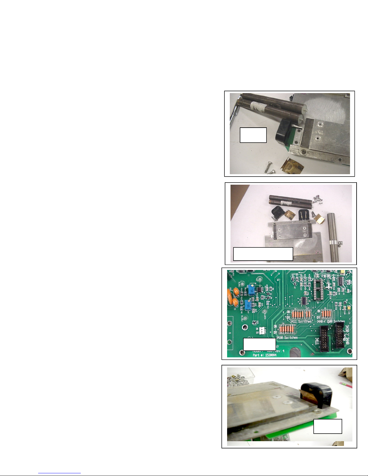
Fig. 5
Disassembling the existing baseboard:
1. Turn off the gauge and place the gauge on a
standard block. Remove the top shell,
disconnect the batteries, discharge the high
voltage and remove the existing baseboard
and metal plate assembly.
2. Remove the He3 tube from the assembly by
removing the curved support bracket and
then pulling the tube downward away from
the baseboard.
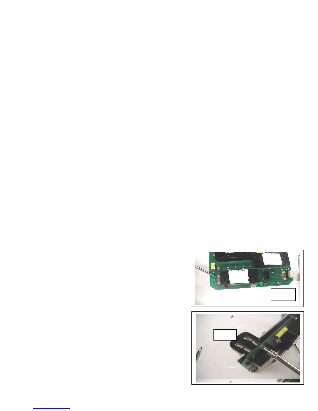
3. Use a 5/16 nut driver to remove the screws
securing the GM tube holders. The GM
tube holders are slotted and are held by the
metal plate. One end of the GM tube holder
will still be connected to the baseboard by
soldered resistors. Slide off the other one
and remove the tubes. Figs 1, 2 and 3.
4. Do not discard the copper grounding
springs, as they are needed with the new
UBB assembly.
5. The nylon spring supports and small coil
springs are located in the resistor connected
end of the GM tubes and may drop out if the
tube is turned downward during removal.
Save these.
6. Separate the metal base plate from the
baseboard by removing the screws on the
top of the baseboard.
7. Slide the metal base plate off the remaining
GM tube holder.
8. From the top of the board, use a de-
soldering tool to disconnect the resistors
from the baseboard. This will allow you to
remove the remaining GM tube holder from
the old baseboard.
9. You are now ready to assemble your new
UBB board.
Assembling the new UBB baseboard:
1. Remove the metal cover from the UBB by
removing the screws.
2. Locate the 3 groups of jumpers on the UBB.
Fig 5.
Fig.3
Reuse these parts
Fig.6
2
Page 3
3. The groups of jumpers are marked as
Fig 6b
S4
S6
“3411” “3430” or “3440/ 3500” switches.
4. To configure the UBB for operation as a
3401/3411baseboard, only the group of
jumpers marked as 3411 switches need to
remain shorted by means of the jumpers.
Carefully remove all of the jumpers from
the groups marked as 3430 switches and
3440/3500 switches by cutting them with
wire cutters.
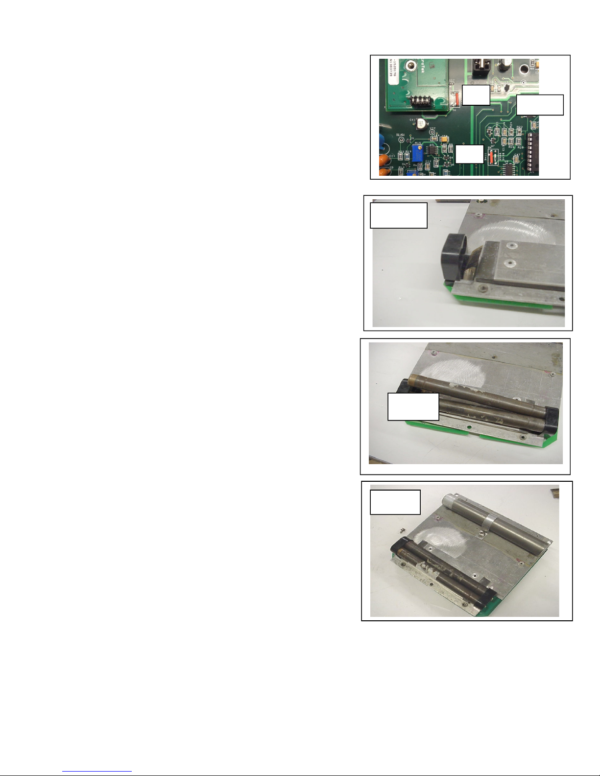
5. Locate the groups of jumpers marked S4 and
S6. Leave the jumpers marked 3411. Cut
the jumpers marked 3500/3430.Fig 6b
6. Place one copper grounding spring between
the bottom side of the UBB and the GM
tube holder with the resistors. Ensure the
resistor leads from the GM tube holder
extend through the solder holes of the UBB.
Secure the GM tube holder with the
mounting screws. Solder the resistor leads
to the UBB at GM1 and GM2 points. Fig.6.
7. Slide the metal base plate into the grooves
on the GM tube holder.
8. Secure the UBB to the metal base plate with
the screws taken out.
9. Place the GM tubes into the secured GM
tube holder making sure the end of the GM
tube with springs and nylon spring supports
are the end inserted into this connector.
10. Install the other copper ground spring and
GM tube holder by sliding it onto the metal
base plate and securing it to the UBB with
the appropriate screws. Fig. 7 and 8.
11. Reinstall the He3 tube and mounting
bracket. Fig.9.
12. Place the complete assembly back into the
gauge and secure it with the appropriate
screws.
13. Connect the batteries and control board
(front panel) to the UBB.
14. The UBB assembly is now complete and
ready for electrical adjustment and setup.
15. Proceed to Section D.
Fig.7
Fig.8
Fig.9
3
Page 4

SECTION B – Installing the UBB in a 3430 or 3440 Gauge:
NOTE: In addition to the UBB, the UBB Base Board Kit, part
#1520103, is required to replace baseboards in Troxler Model 3430 and
3440 gauges.
The Base Board Kit Includes:
1. Metal base plate assembly (1)
2. GM tube interface circuit board (1)
3. 4-40 screws (4 each)
4. 6-32 x .500 (6 each)
5. 6-32 x .375 (3 each)
6. Interface board header (1)
7. # 4 lock washer (4 each)
8. # 6 lock washer (9 each)
9. metal cover box
Installing the UBB in a 3430 or 3440 gauge:
Use the following parts from the existing 3430/3440
gauge along with your new UBB and Base Board
kit to complete this task.
1. GM tubes (2)
2. GM tube holder and screws(1)
3. He3 tube (1)
4. Curved He3 tube support and screw
5. Screws and washers that attach circuit
board to metal plate.
6.
Screws and washers that attach baseboard
assembly to gauge.
7.
Small angle bracket at GM tube end.
Disassembling the existing baseboard:
1. Turn off the gauge, place the gauge on a
standard block, remove the top shell,
disconnect the batteries, discharge the high
voltage and remove the existing baseboard/
base plate assembly.
2. Remove the He3 tube from the existing
baseboard by removing the metal bracket and
Fig. 10
Fig. 11
4
Fig. 12
Page 5

pulling the tube downward away from the
S4
S6
existing baseboard.
3. Remove the screws securing the plastic GM
tube holder. (Fig 10)
4. Carefully remove the GM tubes by prying
them out of the connectors with a small flat
screwdriver.
Assembling the new UBB baseboard:
1. Remove the metal cover from the UBB by
removing the 3 screws and washers. Fig. 11.
2. Locate the 3 groups of jumpers on the UBB.
See Fig. 5.
3. The groups of jumpers are marked as “3411”
“3430” or “3440/ 3500” switches. To
configure the UBB for operation baseboard
of your choice, only the group of jumpers
for your selection of baseboard need to
remain shorted by means of the jumpers.
Carefully remove all jumpers of the
remaining 2 groups by cutting them with
wire cutters.
4. Locate the groups of jumpers marked S4 and
S6. Leave the jumpers marked 3500/3430.
Cut the jumpers marked 3411. Fig 12b
5. Looking down on the UBB with the jumpers
at the bottom section of the board, locate the
3 holes on the left side. Solder the GM
assembly header on the underside the board
at this location. The header should sit flush
on the board. Fig. 12.
6. Attach the small angle bracket to the new
metal base plate. Fig 13a &13b.
7. Secure the UBB to the base plate with the
appropriate screws. Use the provided flat
washers under the lock washers. Fig 14.
8. Carefully press the GM tubes into the
contacts on the GM tube interface board.
9. Slide the GM tubes into the GM tube holder
mounted on the metal base plate and attach
the GM tube interface board to the baseboard
mounted header. Fig. 15.
10. Secure the GM tube interface board with the
provided 4-40 screws and washers. Fig. 16.
12b
Fig. 13a
Fig. 13b
Fig. 14
5
Page 6

11. Reinstall the He3 tube and mounting bracket.
12. Place the complete UBB assembly back into
the gauge and secure it.
13. Connect the batteries and scaler to the UBB.
14. For 3440 gauges connect the depth strip to
the header on the upper edge of the UBB.
Fig. 16.
15. The UBB assembly is now complete and
ready for setting up.
SECTION C – Installing the UBB in
an InstroTek 3500 Gauge:
All existing hardware from the presently installed
3500 baseboard is utilized for the replacement
baseboard.
Disassembling the existing baseboard:
1. Turn off the gauge, place the gauge on a standard
block, remove the top shell, disconnect the
batteries, and remove the 3 screws securing the
metal cover from the top of the existing
baseboard. Discharge the high voltage by shorting
the pins on the upper left side of the baseboard.
2. Remove the 6 screws securing the existing
Base board to the base plate.
3. Using both hands, gently pull the baseboard
directly upward removing it from the base plate.
Assembling the new UBB baseboard:
1. Align the HE3 tube with the connector on the
new UBB and firmly press the UBB downward.
Verify the HE3 tube makes a secure connection to
the UBB connector.
2. Gently raise the lower left side of the UBB and
visually align the GM pins on the UBB with
the GM header assembly connected to the
baseplate.
3. Press down on the UBB seating the GM pins into
the GM tube header.
4. Secure the UBB to the baseplate with the 6
baseboard securement screws.
Fig. 15
Fig. 16
6
Page 7

5. Before installing the metal UBB cover verify the
setup procedure in Section D.
SECTION D -
and Setup Procedures
Electronic Adjustment
1. Place the gauge on the standard block. Turn
on the gauge.
Setting up the moisture signal:
2. Set the oscilloscope to 200 mV scale, ac coupled and very small
µsec(s) time base.
3. Locate the test point “M-ADJ” on the UBB. This is located at the
upper right of the UBB below the battery connections.
4. Place the scope probe in the test point and connect the ground lead
of the probe to the gauge aluminum base.
5. Using the scope and small screwdriver, adjust potentiometer R33
until you have a moisture signal at this test point with peak
amplitude of 600 mV.
Setting up the Density signal:
6. Locate the test point “D2-ADJ” and “D1-ADJ” on the UBB.
These are located on the lower side of the UBB left of the jumpers.
7. Place the scope probe in one test point and connect the ground lead
of the probe to the aluminum gauge base.
8. Using the scope and small screwdriver, adjust potentiometer R15
(for “D2-ADJ”) and R7 (for “D1-ADJ”) until you have a density
signal for each of these test points with a peak amplitude of 600
mV.
Reassemble the gauge:
9. Turn off the gauge and discharge the high voltage circuit by
shorting the “HV-Discharge” pins on the upper left corner of the
UBB with an insulated metal object such as a screwdriver.
10. Place and secure the metal cover on the UBB.
11. Reassemble the gauge.
12. The gauge will need to re-calibrated or
verified for accurate results according to
ASTM D2922.
7
 Loading...