

Page 1

Instruction Manual
MODEL 3216
ROOF MOISTURE
GAUGE
Troxler Electronic Laboratories, Inc.
3008 Cornwallis Rd. · P.O. Box 12057
Research Triangle Park, NC 27709
Phone: 1.877.TROXLER
Outside the USA: +1.919.549.8661
Fax: +1.919.549.0761
www.troxlerlabs.com
Page 2

Troxler Gauges are protected by U.S.
and foreign patents
Copyright © 1981 - 2006
Troxler Electronic Laboratories, Inc.
All Rights Reserved
No part of this manual may be reproduced or
transmitted in any form or by any means, electronic
or mechanical, including photocopying, recording,
or information storage and retrieval systems, for
any purpose without the express written permission
of Troxler Electronic Laboratories, Inc.
PN 103367
October 2006
Edition 4.1
Page 3

TROXLER SERVICE CENTERS
Troxler Corporate Headquarters
3008 Cornwallis Road
Research Triangle Park, NC 27709
Phone: 1.877.TROXLER (1.877.876.9537)
Outside the U.S.A.: +1.919.549.8661
P.O. Box 12057
Fax: +1.919.549.0761
Web: www.troxlerlabs.com
Phone: 1.877.TROXLER (1.877.876.9537)
Technical Support
E-mail: TroxTechSupport@troxlerlabs.com
Midwestern Branch Office
1430 Brook Drive
Downers Grove, IL 60515
Fax: 630.261.9341
Western Regional Branch Office
11300 Sanders Drive, Suite 7
Rancho Cordova, CA 95742
Fax: 916.631.0541
Southwestern Branch Office
2016 East Randol Mill Road
Suite 406
Arlington, TX 76011
Fax: 817.275.8562
Florida Service Center
2376 Forsyth Road
Orlando, FL 32807
Fax: 407.681.3188
Canadian Branch Office
7125 Pacific Circle, Unit 13
Mississauga, Ontario L5T-2A5
Canada
Fax: 905.564.7092
Troxler European Subsidiary
Troxler Electronics GmbH
Gilchinger Strasse 33
D.82239 Alling nr.
Munich, Germany
Phone: ++49.8141.71063
Fax: ++49.8141.80731
E-mail: troxler@t-online.de
Page 4

NOTES
Page 5

TABLE OF CONTENTS
I. INTRODUCTION AND SPECIFICATIONS
II. OPERATING INSTRUCTIONS
III. FIELD MEASUREMENTS
IV. SENSITIVITY DATA ................. 4-1
V. PERIODIC MAINTENANCE
VI. SERVICE
I-A. Introduction . . . . . . . . . . . . . . . 1-1
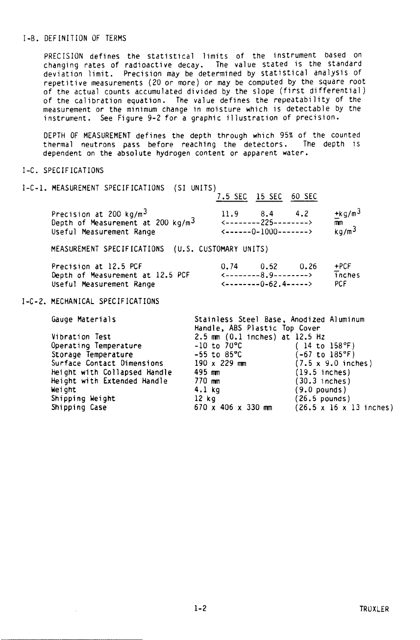
I-B. Definition of Terms . . . . . . . . . . . 1-2
I-C. Specifications . . . . . . . . . . . . . . 1-2
II-A. Getting Acquainted . . . . . . . . . . . . 2-1
II-B. Control Functions and Operations . . . . . 2-1
II-C. Test Functions . . . . . . . . . . . . . . 2-2
III-A. Data Collection . . . . . . . . . . . . . 3-1
III-B. Manual Analysis of Data . . . . . . . . . 3-4
III-C. Computer Aided Analysis of Data . . . . . 3-11
III-D. Vertical Wall Measurements . . . . . . . . 3-12
V-A. Battery Charging . . . . . . . . . . . . . 5-1
V-B. Cleaning ................. 5-1
V-C. Internal Condensation . . . . . . . . . . 5-1
V-D. Gauge Disassembly . . . . . . . . . . . . 5-2
V-E. Leak Test Procedure . . . . . . . . . . . 5-2
VI-A. Equipment Required . . . . . . . . . . . . 6-1
VI-B. Gauge Electronics . . . . . . . . . . . . 6-2
VI-C. Statistical Stability . . . . . . . . . . 6-5
VI-D. Troubleshooting Hints . . . . . . . . . . 6-7
VI-E. Service Centers . . . . . . . . . . . . . 6-8
VII. PARTS LIST
VIII. THEORY OF MEASUREMENT
IX. FACTORY CALIBRATION
X. RADIATION THEORY AND SAFETY
VII-A. Replacement Parts . . . . . . . . . . . . 7-1
VII-B. Accessories . . . . . . . . . . . . . . . 7-1
VIII-A. Neutron Radiation and Matter . . . . . . . 8-1
VIII-B. Moisture Geometry . . . . . . . . . . . . 8-3
IX-A. Moisture Calibration . . . . . . . . . . . 9-1
IX-B. Moisture Performance Parameters . . . . . 9-2
X-A. Radiation Theory . . . . . . . . . . . . . 10-1
X-A-1. Atomic Structure . . . . . . . . . . . . . 10-1
X-A-2. Radiation Theory . . . . . . . . . . . . . 10-2
X-A-3. Radiation Terminology . . . . . . . . . . 10-2
X-B-1. Radiation Statistics . . . . . . . . . . . 10-2
X-B. Radiation Safety . . . . . . . . . . . . . 10-3
X-B-1. Types of Radiation . . . . . . . . . . . . 10-3
X-B-2. Limiting Exposure . . . . . . . . . . . . 10-4
X-B-4. Monitoring Radiation . . . . . . . . . . . 10-5
i
Page 6

Table of Contents (cont'd)
X-B-4. 3216 Radiation Profile . . . . . . . . . . 10-6
X-B-5. Source Encapsulation . . . . . . . . . . . 10-7
X-B-6. Emergency Procedures . . . . . . . . . . . 10-7
XI. TRANSPORTATION AND SHIPPING
APPENDIX A
XI-A. Requirements . . . . . . . . . . . . . . . 11-1
XI-A-1. Certificate of Competent Authority . . . . 11-1
XI-A-2. Results of Type A Package Testing . . . . 11-2
XI-A-3. Emergency Response Sheet . . . . . . . . . 11-2
XI-A-4. Emergency Response Telephone Number . . . 11-2
XI-A-5. Labeling Requirements . . . . . . . . . . 11-2
XI-A-6. "Bill of Lading" Requirements . . . . . . 11-2
XI-A-7. Locking or Sealing of Package . . . . . . 11-3
XI-A-8. Inspection of Package Prior to Shipment . 11-3
XI-A-9. Accident Notification Requirements . . . . 11-3
XI-A-10 Hazmat Training . . . . . . . . . . . . . 11-3
XI-B. Shipping Forms . . . . . . . . . . . . . . 11-3
BASIC Listing for Standard Deviation . . . . . . . AI
Sample Output from Standard Deviation Program . . . AII
ii
Page 7

LIST OF ILLUSTRATIONS
Figure Description Page
3-1 Gridded Roof Plan 3-3
3-2 Roof Measurement Data 3-3
3-3 Histogram of Sample Data 3-4
3-4 Normal Distribution With
Confidence Limits
3-5 Normal Distribution Overlaying
Histogram
3-6 Standard Deviation for Grouped
Data
3-7 Percent Moisture Correlation Graph
Data
3-8 Graphic Interpretation of Roof
Survey
3-9 Computer Aided Plot 3-11
5-1 Leak Test Analysis Form 5-3
6-1 Interior Layout 6-3
6-2 Block Diagram of Gauge Electronics 6-4
6-3 Statistical Test Data 6-5
8-1 Neutron Interaction Data 8-3
8-2 Effect of Neutron Source-Detector
Distance
8-3 Effect of Moisture on Depth of
Measurement
9-1 3216 Calibration Data 9-4
9-2 Graphic Interpretation of Moisture
Calibration
10-1 Diagram of an Atom 10-1
10-2 Variation of Radioactive Emission 10-3
10-3 Effect of Distance on Exposure 10-4
10-4 3216 Radiation Profile 10-6
11-1 Sample Intra-company "Bill of
Lading"
11-2 Sample Common Carrier "Bill of
Lading"
11-3 Sample Shipper's Declaration of
Dangerous Goods
11-4 Sample Federal Express Form 11-7
3-5
3-6
3-7
3-8
3-9
8-4
8-5
9-6
11-4
11-5
11-6
iii
Page 8

This page intentionally blank
iv
Page 9

Page 10
Page 11

I-C-3. CALIBRATION SPECIFICATIONS
Number of Standards 2
Accuracy of Standards ±4.0%
I-C-4. RADIOLOGICAL SPECIFICATIONS
Neutron Source 1.48 ± 10% GBq
Source Form Stainless steel,
Source Classification ANSI-C54444
per ANSI N542-1977
Shielding Lead and Polyethylene
Maximum Surface Dose Rates See Radiation Profile on
Shipping Case DOT 7A, Type A, Yellow II
Special Form Approval Am-241, SPECIAL FORM
Gauge Classification per ANSI-54-685-685-R2
ANSI N538-1979
I-C-5. ELECTRICAL SPECIFICATIONS
Time Accuracy and Stability ± 0.005% ± 0.0002%/°C
Power Supply Stability ± 0.01%/°C
Battery Capacity 14 W-hr
(40 ± 10% mCi)
70,000 n/sec yield,
TEL A-102451
encapsulated
page 10-6
Label, 0.1 TI
Certificate GB:SFC 7
Charge Source 115/230 V, 50-60 Hz
Battery Recharge Time
AC Charger 14 hr
DC Charger 3 hr
LCD 4 digits
Largest Number Displayable 9999
Count Registers 1
Power Consumption 0.08 W
Power Consumption after 0.001 W
Automatic Battery Cutoff
Battery packs are fully protected against overcharge and
overdischarge. Low Battery alarm is indicated on the display
several hours prior to automatic cutoff.
TROXLER 1-3
or 12-15 VDC
Page 12

Page 13

Page 14

Page 15

Page 16

III-A-2. LAYOUT GRID ON ROOF
The grid pattern (at the selected size) must be laid out
on the roof. Paint, strings, marked ropes, or other
methods can be used to define the grid intersections on
the roof.
One popular method is to use two marked ropes, placed
parallel on opposite sides of the roof. A third marked
rope is stretched between the two parallel ropes. With
spray paint can spot the roof at each marking on the
rope. The "marking stick" listed in the Accessories
Parts List (Section VII-B) is especially useful for this
purpose.
III-A-3. DRAWING OF ROOF PLAN
Make a scaled drawing of the roof's top view. Note on
this drawing all roof structures (drains, heating and
air conditioning units, ventilation shafts, etc.). If
there are no roof structures or other details that
indicate building orientation, then note the north
orientation on the drawing.
Any roof structures the user wishes included on a plot
must also by shown on the roof plan.
III-A-4. COLLECT MEASUREMENT DATA
Set the POWER/TIME switch to the desired accumulation
time period. Use the gauge to make a measurement count
at each grid intersection. Record this count at the
correct position.
III-A-5. CUT CORE SAMPLES
Nuclear gauges register relative hydrogen levels. If
absolute moisture levels are needed, one must correlate
count rates and actual moisture levels. Correlation is
normally done via core samples.
The core samples should be chosen to include the widest
range of count rates possible. The roof plan count rate
data will be useful in choosing where to cut core
samples. If a limited number of core samples are to be
cut, then they should be made at sites (determined from
the count data) that indicate a transition from dry to
wet.
3-2 TROXLER
Page 17

Page 18

Page 19

Page 20

Page 21

Page 22

Page 23

Page 24

Page 25

Page 26

Page 27

Page 28

Page 29

Page 30

Page 31

Page 32

Page 33

Page 34

Page 35

Page 36

Page 37

Page 38

Page 39

Page 40

VI-E. TROXLER SERVICE CENTERS
Troxler Corporate Headquarters
3008 Cornwallis Road
Research Triangle Park, NC 27709
Phone: 1.877.TROXLER (1.877.876.9537)
Outside the U.S.A.: +1.919.549.8661
P.O. Box 12057
Fax: +1.919.549.0761
Web: www.troxlerlabs.com
Phone: 1.877.TROXLER (1.877.876.9537)
Technical Support
E-mail: TroxTechSupport@troxlerlabs.com
Midwestern Branch Office
1430 Brook Drive
Downers Grove, IL 60515
Fax: 630.261.9341
Western Regional Branch Office
11300 Sanders Drive, Suite 7
Rancho Cordova, CA 95742
Fax: 916.631.0541
Southwestern Branch Office
2016 East Randol Mill Road
Suite 406
Arlington, TX 76011
Fax: 817.275.8562
Florida Service Center
2376 Forsyth Road
Orlando, FL 32807
Fax: 407.681.3188
Canadian Branch Office
7125 Pacific Circle, Unit 13
Mississauga, Ontario L5T-2A5
Canada
Fax: 905.564.7092
Troxler European Subsidiary
Troxler Electronics GmbH
Gilchinger Strasse 33
D.82239 Alling nr.
Munich, Germany
Phone: ++49.8141.71063
Fax: ++49.8141.80731
E-mail: troxler@t-online.de
6-8 TROXLER
Page 41

VII. PARTS LIST
VII-A. REPLACEMENT PARTS
103021 Liquid Crystal Display
103286 Moisture Preamplifier Module (2 req'd)
103300 Baseboard PCB Ass'y (without modules)
103321 Power Controller Module
103325 Scaler PCB Ass'y
103355 Battery Pack (2 req'd)
103356 Flat Cable Ass'y
103374 Ratemeter
104094.0001 Moisture Tube Assembly (2 req'd)
104639 High Voltage Module, 900 V
108709 High Voltage Module, 1000 V
VII-B. ACCESSORIES
021140 Radiation Sign Kit
102868 Leak Test Kit, Model 3880
102873 1oz Solution Detergent
102876.0005 Leak Test Replacement Packets (4 units)
102957 12 V DC Charger Cable
103367 Instruction Manual
104508 AC Battery Charger, 13.5 V, 140 mA (Dom. Sales)
104509 AC Battery Charger, 13.5 V, 140 mA (Int. Sales)
104621 3216 Case/Foam Ass'y
109661 Troxler Survey Meter
A "marking stick" is useful for spot marking the grid
intersection points on the roof. This or similar holders for
spray paint cans should be available from local surveyors and
construction equipment dealers.
TROXLER 7-1
Page 42

Page 43

Page 44

Page 45

Page 46

Page 47

Page 48

Page 49

IX. FACTORY CALIBRATION
IX-A. MOISTURE CALIBRATION
Many attempts have been made to create satisfactorily
stable moisture standard either by using water and soil
mixes or by simulating moisture by mixing hydrogenbearing materials with other materials simulating soils.
Some standards are totally inaccurate, and some are very
unstable unless particular attention is paid to
During the development of moisture measurement gauges,
The count rate data accumulated during the calibration
Where m is the slope of the calibration curve and b is
The value (b/m) is often referred to as the offset value
maintaining water levels and preventing evaporation.
Troxler Electronic Laboratories, Inc. developed a set of
standards made from laminated sheets of plastic and a
non-absorber of thermal neutrons. This process has been
patented (.) During the process of manufacture the ratio
of plastic (or other hydrogen-bearing material) and a
non-absorber can be accurately controlled. To ensure
uniformity, laminations were chosen rather than mixing
of small particles. Such a mixing process tends to
result in segregation due to the differences in the
specific gravity of the materials. The materials used in
the Troxler standards are non-hydroscopic and have zero
voids, so changes in humidity do not affect the
equivalent water content.
process are used to solve the equation:
Count Rate = m x (Moisture Content) + b
the intercept of the calibration curve. Once the values
of m and b are evaluated, the terms of this equation are
usually re-arranged so that the moisture content can be
computed from the count rate. The resulting equation is:
Moisture Content = (1/m) x (Count Rate) – (b/m)
of the calibration equation.
TROXLER 9-1
Page 50

IX-B. MOISTURE PERFORMANCE PARAMETERS
A computer-generated calibration report is supplied with
the 3216 gauge. This 2-page report summarizes the
calibration process and results. While the 3216 is
intended for relative moisture measurements, it must be
calibrated against known moisture standards to verify
the gauge characteristics. An example of a typical Model
3216 calibration report is shown in Figure 9-1.
A summary of the contents of a Model 3216 calibration
report is presented hereunder. The report consists of
six separate parts, contained on two pages:
1. The first four lines of text at the top of the first
and second pages of the report are the header. His
portion of the calibration report contains data that
identify the gauge itself (gauge serial number, model
number, source serial number, gauge type) and the
date when the calibration was done and the report was
printed.
2. The second section of the calibration report is
composed of two sentences that identify the units
that are used with the different quantities listed in
the calibration report and instruct the user on how
to distinguish these units.
3. The section beginning with “Calibration Measurement
Data” lists the data collected during the calibration
of the gauge that are used to compute the slope and
the intercept of the calibration curve itself. These
data include the moisture values of the two
calibration blocks and the counts that were acquired
by the gauge on these blocks.
4. The section beginning with “Calibration Equation”
explains the form and meaning of the calibration
equation. This section also describes how the
calibration equation is re-arranged in order to
compute soil moisture values directly by using the
gauge count.
9-2 TROXLER
Page 51

5. The section beginning with “Precision for various
measurement times” lists the precision values for the
calibration equation. These precision values are
presented in tabular form and are evaluated at three
different moisture levels and three different
counting times. The precision defines the
repeatability of a measurement or the minimum change
in moisture that is detectable by the gauge. The
precision is the uncertainty (expressed as one
standard deviation) in the measured moisture content
based on the uncertainty (expressed as one standard
deviation) of a given gauge count due to the decay
rates of radioactive material. Figure 9-2, a plot of
a calibration curve for a Model 3216 gauge, includes
a graphic illustration of precision.
6. The second page of the calibration report begins with
the header, followed by six paragraphs of summary
information. This summary information is included to
address specific requirements for calibration
reports. The first paragraph of the summary
information defines the ideal conditions of the
measurement material for which ensure the optimal
performance of the gauge. The second paragraph
references the traceability of the moisture value of
the mag/poly block used in the calibration. The third
paragraph ensures the user that the gauge was
operating properly during and after the calibration,
instructs the user that the report is applicable only
to the specific instrument described in the report,
and informs the user of the identity of the
technician who calibrated this instrument and when it
was calibrated. Paragraph 4 gives the address of the
facility where the gauge was calibrated, and
paragraph five is the special considerations and
limitations statement. Finally, paragraph six
requests that the data in the report not be
misrepresented by omitting or altering its contents,
unless such a modification is formally approved by
Troxler Electronic Labs.
TROXLER 9-3
Page 52

IX.B. MOISTURE PERFORMANCE PARAMETERS (cont’d)
Model: 3216A Serial: 00512 Calib. date: Mar 21, 2005
Source: AM-241/Be Serial: 78-976 Print date: Dec 07, 2005
Neutron Surface Moisture Gauge
******
The performance parameters, calibration constants, and moisture values for this
instrument are listed both in SI units (kilograms per cubic meter) and in
US Customary Units (pounds per cubic foot). In each instance where the SI and
US Customary values differ, the SI will be listed first, followed by the
US Customary Units in parentheses.
******
Calibration Measurement Data
Standard Moisture Content Counts/Min.
kg/M3 (pcf)
--------- ---------------- ---------- Magnesium 0 9.0
Mag/Poly 606 (37.8) 108.4
******
Calibration Equation:
For the form of the linear equation y = mx + b, where x is the independent
variable (moisture content), y is the dependent variable (gauge count),
m is the slope of the calibration curve, and b is the intercept of the
calibration curve, the calibration equation for this gauge is:
y = 0.1640x + 9.000, where x in in units of kilograms per cubic meter
or,
y = 2.626473x + 9.000, where x in in units of pounds per cubic feet.
For the form of the linear equation x = my + b, where x is the independent
variable (moisture content), y is the dependent variable (gauge count),
m is the slope of the calibration curve (also known as the Resolution), and
b is the intercept of the calibration curve, the calibration equation for
this gauge is:
x = 6.0987y - 54.888, where x in in units of kilograms per cubic meter
or,
x = 0.380739y - 3.427, where x in in units of pounds per cubic feet.
******
Precision for various measurement times
Moisture <--------- Measurement Time --------->
kg/m3 (pcf) 7.5 Sec. 15 Sec. 60 Sec
--------- ---------- ---------- --------- 0 ( 0.0) 4.6 (0.29) 3.2 (0.20) 1.6 (0.10)
100 ( 6.2) 7.7 (0.48) 5.4 (0.34) 2.7 (0.17)
200 (12.5) 9.9 (0.62) 7.0 (0.44) 3.5 (0.22)
Troxler Model 3216 Calibration Report - Page 1 of 2
3216 Calibration Data (Sheet 1 of 2)
Figure 9-1
9-4 TROXLER
Page 53

IX.B. MOISTURE PERFORMANCE PARAMETERS (cont’d)
Troxler Model 3216 Calibration Report - Page 2 of 2
Model: 3216A Serial: 00512 Calib. date: Mar 21, 2005
Source: AM-241/Be Serial: 78-976 Print date: Dec 07, 2005
Neutron Surface Moisture Gauge
******
The calibration parameters for this instrument are based upon the measured
material having a uniform moisture content equally distributed throughout the
measured depths. The depth of measurement of this instrument will vary from
100 mm (4 inches) to upwards of 250 mm (10 inches) depending upon the moisture
content of the material. These parameters may be significantly altered if the
material thickness is reduced below the depth of measurement.
The above referenced equipment has been calibrated by the manufacturer to
established and documented procedures. Moisture values for the standards used
in the calibration of this equipment are based upon instrument response in
siliceous soil. Test procedures and supporting documentation are available
upon request
This instrument was found to be mechanically sound and electronically stable both
prior to and after its calibration. All data listed in the preceding page of this
report are applicable to this instrument only. This calibration was performed by
JRS on 03-21-2005 at:
Troxler Electronic Laboratories, Inc.
3008 Cornwallis Road
Research Triangle Park, NC 27709
www.troxlerlabs.com
Special considerations and limitation of use for this device and its calibration are
described in the Manual of Operation and Instruction provided with this instrument.
This report shall not be reproduced, except in full, without the written approval of
Troxler Electronic Laboratories, Inc.
3216 Calibration Data (Sheet 2 of 2)
Figure 9-1
TROXLER 9-5
Page 54

IX.B. MOISTURE PERFORMANCE PARAMETERS (cont’d)
Graphic Interpretation of Moisture Calibration
Figure 9-2
9-6 TROXLER
Page 55

X. RADIATION THEORY AND SAFETY
The quantities of radioactive material contained in Troxler
moisture gauges are quite small, and an operator may safely
use a gauge daily without receiving any biological damage
due to radiation. In addition, each radioactive source is
doubly encapsulated to afford greater protection for the
operator. However, all radioactive sources, no matter how
small, should be handled with care.
The purpose of this section is to acquaint the operator with
the types and characteristics of radiation with which he/she
will be working and to describe methods to ensure safe
operation of Troxler gauges.
X-A. RADIATION THEORY
A more detailed discussion of radiological theory can be
found in the Troxler Nuclear Gauge Safety Training
Program manual, provided at the Troxler radiation safety
class.
X-A-1. ATOMIC STRUCTURE
All materials consist of chemical elements that can not
decompose by ordinary chemical methods. Some examples
are:
(H) Hydrogen (C) Carbon (O) Oxygen
(U) Uranium (Cf) Californium (Co) Cobalt
Each element contains an atom with a unique structure.
The atom consists of smaller particles such as protons,
neutrons and electrons. The protons and neutrons are
grouped together in the nucleus (Figure 10-1). The
electrons orbit the nucleus. An atom is normally
electrically neutral because the positive protons cancel
out the negative electrons.
Diagram of an Atom
Figure 10-1
Protons carry a positive charge and are described as
having a mass of one. Neutrons have a neutral charge and
also have a mass of one. Electrons carry a negative
charge and essentially have no mass.
MASS
(ATOMIC WEIGHT SCALE) CHARGE
Protons 1.0073 +1
Neutrons 1.0087 0
Electrons 0.0006 -1
TROXLER 10-1
Page 56

Since protons and neutrons are clustered together in the
nucleus, the mass of an atom is concentrated in the
nucleus. The atom in Figure 10-1 has two protons and two
neutrons; therefore, it is a helium atom. The atomic
weight of an atom is the sum of the protons and neutrons.
X-A-1. RADIATION THEORY
Radioactivity is the spontaneous breakdown of unstable
nuclei (radioisotopes) with the resulting emission of
radiation. The basic unit of radiation used in the U.S.
is the curie (Ci). The Curie is defined as 3.7 x 10
disintegrations of nuclei per second. In the "special
form," encapsulated sealed source used in the 3216, the
unit of measure is the millicurie (1/1,000 of a curie).
The SI unit of radiation is the Becquerel (Bq). The
Becquerel equals to one disintegration per second.
Therefore, one curie equals 3.7 x 10 Becquerels.
The strength of radioactive material is measured by its
activity, or rate of decay. This activity decreases with
time. The length of time it takes a given amount of
radioactive material to decay to half of its original
strength is referred to as the "half-life." The halflife of the 3216's source is approximately 432 years.
X-A-3. RADIATION TERMINOLOGY
10
10
The curie, defined as the quantity of radioactive
material giving 3.7 x 10 disintegrations per second, is
equal to the number of disintegrations/second of one gram
of radium-226. Note that the source used in the 3216 is
small, with quantities expressed in millicurie (mCi).
The rad or "radiation absorbed dose," is the unit of
absorbed dose equal to 0.01 Joules/kg in any medium. To
account for the effect of various types of radiation on
biological tissue, the "roentgen equivalent man" (rem) or
more appropriate for Troxler users - the millirem - is
used when measuring radiation dose. The unit rem is
derived from scaling the radiation absorbed dose (rad) by
a quality factor (QF). One rem is equal to the exposure
of one rad of gamma radiation. For example, the average
energy of an americium-241:beryllium neutron source is
4.5 MeV. The quality factor (QF) for this source is
approximately 10. The absorbed dose of 1 rad of neutron
radiation gives a dose equivalent of (absorbed dose x QF)
10 rem.
X-A-4. RADIATION STATISTICS
Radioactive emission is a random process. The number of
emissions in a given time period is not constant but
varies statistically about an average value. The
variation about the true mean value is a Poisson
distribution (Figure 10-2). In this distribution, the
standard deviation (F) about the mean (n) is defined as:
10
F = % n
10-2 TROXLER
Page 57

When the mean is greater than 100, the Poisson
distribution can be closely approximated by the normal
distribution (Figure 10-2). The normal distribution
predicts the probability that any given count rate will
fall within a selected region about the mean.
Normal Distribution
Figure 10-2
Variation of Radioactive Emission
Using the mean of a larger number of counts to
approximate the true mean, the distribution shows that
68.3% of the time the count rate obtained will be within
±1 standard deviation of the mean. The figure above shows
the probabilities for three different standard deviations
of the mean. A statistical stability test may be
performed to compare the experimental standard deviation
to the theoretical standard deviation (see AII).
X-B. RADIATION SAFETY
This section provides a brief discussion of general
radiation safety. The exposure profile for the Model
3216 gauge is also included, along with a discussion of
the source encapsulation.
X-B-1. TYPES OF RADIATION
The radioactive source in the Model 3216 produces three
types of radiation:
Alpha Particles
Gamma Rays (Photons)
Neutrons
The alpha particles are stopped by the source capsule.
Only the gamma and neutron radiation can contribute to
any occupational radiation exposure.
TROXLER 10-3
Page 58

Gamma radiation is electromagnetic radiation, as are
x-rays, radio waves, and visible light. Visible light
and gamma rays have no mass, a zero electrical charge and
travel at the speed of light. Gamma rays are energetic
and penetrating. Dense materials (i.e., lead, cadmium,
etc.) provide the best shielding against gamma radiation.
Neutron radiation allows measurement of the hydrogen
(moisture) content in a material because the neutrons are
slowed by collisions with materials containing hydrogen
atoms (i.e. water, polyethylene, etc.). Neutrons have a
neutral charge and are very penetrating.
X-B-2. LIMITING EXPOSURE
Under normal conditions a full time operator of the 3216
will receive less than 150 millirem per year.
Taking advantage of all available means to limit
radiation exposure is always recommended. The three
methods of limiting exposure are:
These methods are a part of an "ALARA" (As Low As
Reasonably Achievable) program.
TIME
TIME
DISTANCE
SHIELDING
The simplest way to reduce exposure is to keep the time
spent around a radioactive source to a minimum. If time
is cut in half, so is the exposure, with all other
factors remaining constant.
DISTANCE
Distance is another effective means to reduce radiation
exposure. A formula known as the "inverse square law"
relates the radiation exposure rate to distance (Figure
10-3). Doubling the distance from a radiation source
reduces the exposure to one-fourth its original value.
If the distance is tripled, the exposure is reduced by a
factor of nine, etc.
Effect of Distance on Exposure
Figure 10-3
10-4 TROXLER
Page 59

SHIELDING
Shielding is any material used to reduce the radiation
reaching the user from a radioactive source. While some
types of radiation such as alpha particles may be stopped
by a single sheet of paper, other particles such as gamma
rays and neutrons require much more shielding. Dense
materials, such as lead, shield gamma rays. Materials
containing large amounts of hydrogen, such as
polyethylene, shield neutrons. The Model 3216 has
shielding built into the system which reduces the
exposure.
X-B-3. MONITORING RADIATION
Government agencies set occupational exposure limits.
The current limit in the United States and many other
countries is 5,000 millirem per year. Under average
conditions a full time employee working with the 3216
will receive less than 150 millirem per year.
Anyone working with or near radioactive materials is
subject to the limits of occupational exposure and must
complete a radiation safety training course to be
designated an authorized user. As an authorized user, an
individual so designated must work in a "controlled"
environment to the extent that their exposure to
radiation must be monitored. Several means of personnel
monitoring or dosimetry exist; the most common methods
are film badges and TLD badges.
TROXLER 10-5
Page 60

X-B-4. 3216 RADIATION PROFILE
RADIATION PROFILE FOR 3216/3218 GAUGE
LOCATION
FRONT 0.20 3.0 3.2 * 0.8 0.8 * 0.3 0.3 * * *
BACK * 0.4 0.4 * 0.2 0.2 * 0.1 0.1 * * *
SIDES 0.15 1.4 1.55 * 0.5 0.5 * 0.3 0.3 * * *
TOP * 1.5 1.5 * 0.6 0.6 * 0.3 0.3 * * *
BOTTOM 1.00 4.5 5.5 * 2.5 2.5 * 0.5 0.5 * 0.1 0.1
HANDLE * 0.3 0.3 * 0.15 0.15 * * * * * *
LOCATION
LEFT 0.4 1.3 1.7 * 0.4 0.4 * 0.1 0.1
BACK * 0.2 0.2 * * * * * *
RIGHT * 0.2 0.2 * * * * * *
FRONT * 0.7 0.7 * 0.2 0.2 * * *
BOTTOM * 0.4 0.4 * 0.2 0.2 * * *
TOP * 0.3 0.3 * * * * * *
SURFACE 10 cm 30 cm 1 m
Gamma Neutron Total Gamma Neutron Total Gamma Neutron Total Gamma Neutron Total
RADIATION PROFILE FOR 3216 GAUG E IN PLASTIC CASE
SURFACE 10 cm 30 cm 1 m
Gamma Neutron Total Gamma Neutron Total Gamma Neutron Total Gamma Neutron Total
1. Dose rates measured by the State of North Carolina Department of Environment, Health and Natural
Resources, Division of Radiation Protection.
2. Gamma Measurements in case made using Ludlum 14C Survey Meter, Calibrated March 1990.
3. Neutron Measurements in case made with Nuclear Research Corp. Model NP-2 Survey Meter, Calibrated
March 1990.
4. Gamma Measurements of gauge alone made with a Victoreen Model 2035 Survey Meter.
5 Neutron Measurements of gauge alone made with a Nuclear Research Corporation Model NP-2 Survey Meter
(detector physical location is 11.5 mm inside thermalizing housing).
6. Dose rates for 40 mCi Am-241:Be source.
7. * indicates a reading of less than 0.1 millirem/hour.
NOTE: RADIATION DOSE RATES IN MILLIREMS PER HOUR
Figure 10-4
10-6 TROXLER
Page 61

X-B-5. SOURCE ENCAPSULATION
The source in the Model 3216 meets regulatory
requirements of U.S. and international authorities as
"SPECIAL FORM," or encapsulated, sealed source material.
The "sealed" source used is encapsulated to prevent
leakage of the radioactive material and meet radiation
safety requirements.
Proper use of this instrument (following the instructions
in this manual) and the shielding design of the
instrument will keep the exposure levels at a minimum
under normal conditions. It is, however, required that
personnel dosimetry be used when using the 3216.
X-B-6. EMERGENCY PROCEDURES
If the nuclear gauge is lost or stolen, then immediately
notify the Radiation Safety Officer (RSO).
The gauge owner should complete the emergency contact information on
the lines furnished below.
The company RSO is ___________________________________.
Call the RSO at _______________________________________.
The regulatory agency is ________________________________.
Call the agency at _____________________________________.
If a gauge is damaged, then follow the steps below:
T Locate the gauge and/or source.
T Do not touch or move the gauge.
T Immediately cordon off an area around the nuclear
gauge and/or source. A radius of fifteen feet (5 m)
will be sufficient. Do not leave the area unattended.
T Keep all unauthorized personnel from the nuclear
gauge.
T If a vehicle is involved, it must be stopped until the
extent of contamination, if any, can be established.
T The gauge user should perform a visual inspection of
the nuclear gauge to determine if the source housing
and/or shielding has been damaged.
T Use a survey meter to measure the dose rate at a
distance of three feet (1 m) from the gauge.
TROXLER 10-7
Page 62

T Contact the company RSO (name and number given at the
beginning of this section). Provide the RSO with the
following:
Ë the date, time, and location of the accident,
Ë the gauge model and serial number,
Ë the nature of the accident,
Ë the location and condition of the gauge and/or
source,
Ë the dose rate at three feet (1 m) from the gauge.
T If you are unable to reach the RSO, then call your
regulatory agency (name and number given at the
beginning of this section).
T Follow the instructions of the RSO. The RSO should
report the incident to the regulatory agency. The RSO
may also be required to notify the USDOT of accidents
during transport.
T Before shipping a damaged gauge to Troxler, obtain a
RGA (returned goods authorization) number from the
Troxler RSO.
10-8 TROXLER
Page 63

XI. TRANSPORTATION AND SHIPPING
Devices containing radioactive materials must be transported
in accordance with the rules of the U.S. Department of
Transportation (DOT) and the International Atomic Energy
Agency (IAEA). The IAEA recommendations have been codified
in the International Air Transport Association (IATA)
Dangerous Goods Regulations. International customers should
consult their local government or licensing authority for
applicable regulations.
XI-A. U.S. SHIPPING REQUIREMENTS
The U.S. DOT hazmat regulations (49 CFR, Parts 100-185)
apply any time a nuclear device is transported by motor
vehicle on a public highway or by other means of
transport (rail, air, ship).
The major requirements for transporting a nuclear gauge
in the United States are listed below. For more detailed
information about these requirements, please refer to the
Troxler Transportation Guide.
Ë A copy of the current IAEA Certificate of Competent
Authority for each source in the gauge (Special Form
Certificate) must be kept on file. Current versions
can be downloaded from the Troxler website,
www.troxlerlabs.com.
Ë A copy of the results of the Type A package testing
must be kept on file.
Ë Hazmat employee training records must be kept on
file.
Ë An Emergency Response Information document must be
in the vehicle and immediately accessible to the
driver.
Ë A properly completed bill of lading must be in the
vehicle and immediately accessible to the driver.
The shipping papers must include a 24-hr emergency
response phone number.
Ë If shipping by air, a Shipper’s Declaration for
Dangerous Goods must accompany the air waybill.
Ë The package must be properly marked and labeled in
accordance with hazmat regulations.
Ë The package must have a tamper-evident seal.
Ë The package must be inspected prior to each
shipment.
Ë The package must be securely blocked and braced in
the vehicle to prevent shifting during transport.
TROXLER 11-1
Page 64

XI-A-1. ACCIDENT NOTIFICATION REQUIREMENTS
In the event of a reportable incident involving
radioactive material, notify the licensing agency as soon
as practical. The operator is also required to notify, at
the earliest practical moment, the U.S. DOT at
1-800-424-8802 of an accident that occurs during the
course of transportation (including loading, unloading,
and temporary storage) in which fire, breakage, spillage,
or suspected contamination occurs involving shipment of
radioactive materials.
XI-A-2. HAZMAT TRAINING
The U.S. DOT regulations require every hazmat employer to
train, test, certify, and maintain records for each
hazmat employee. Hazmat training applies to anyone who
transports or prepares for transport radioactive
materials. Refresher training is required every three
years.
XI-B. CANADIAN SHIPPING REQUIREMENTS
The Transportation of Dangerous Goods Act and Regulations
(TDG) and Transport Packaging of Radioactive Materials
Regulations (TPRM) apply any time a nuclear device used
in commerce is transported by any means in Canada.
For training and accident notification requirements,
consult the Transportation Of Dangerous Goods
Regulations. For further information on transporting a
nuclear device, contact the transportation section of The
Canadian Nuclear Safety Commission (CNSC).
11-2 TROXLER
Page 65

APPENDIX
Page 66

Page 67

Page 68

 Loading...