

Page 1

Manual of Operation and Instruction
Model 3191
True Mold Angle
Device
for the
Model 4141 Gyratory Compactor
Troxler Electronic Laboratories, Inc.
3008 Cornwallis Road • P.O. Box 12057
Research Triangle Park, NC 27709
Phone: 1.877.TROXLER
Outside the U.S.A.: +1.919.549.866 1
Fax: +1.919.549.0761
www.troxlerlabs.com
Page 2

Troxler products are protected by U.S. and foreign patents
Copyright © 2002 – 2005
Troxler Electronic Laboratories, Inc.
All Rights Reserved
No part of this manual may be reproduced or transmitted in any
form or by any means, electronic or mechanical, including
photocopying, recording, or information storage and retrieval
systems, for any purpose without the express written permission of
Troxler Electronic Laboratories, Inc.
PN 109903
February 2005
Edition 2.0
ii
Page 3

TROXLER SERVICE CENTERS
Troxler Corporate Headquarters
3008 Cornwallis Road
Research Triangle Park, NC 27709
Phone: 1.877.TROXLER (1.877.876.9537)
Outside the U.S.A.: +1.919.549.8661
Fax: +1.919.549.0761
Web: www.troxlerlabs.com
Technical Support
Phone: 1.877.TROXLER (1.877.876.9537)
E-mail: TroxTechSupport@troxlerlabs.com
Midwestern Branch Office
1430 Brook Drive
Downers Grove, IL 60515
Fax: 630.261.9341
Western Regional Branch Office
11300 Sanders Drive, Suite 7
Rancho Cordova, CA 95742
Fax: 916.631.0541
Southwestern Branch Office
2000 East Randol Mill Road
Suite 611
Arlington, TX 76011
Fax: 817.275.8562
P.O. Box 12057
Florida Service Center
2376 Forsyth Road
Orlando, FL 32807
Fax: 407.681.3188
Canadian Branch Office
7125 Pacific Circle, Unit 13
Mississauga, Ontario L5T-2A5
Canada
Fax: 905.564.7092
Troxler European Subsidiary
Troxler Electronics GmbH
Gilchinger Strasse 33
D.82239 Alling nr. Munich, Germany
Phone: ++49.8141.71063
Fax: ++49.8141.80731
E-mail: troxler@t-online.de
Model 3191 True Mold Angle Device iii
Page 4

NOTES
iv
Page 5

INTRODUCTION
Troxler’s Model 4141 Gyratory Compactor provides safe, reliable
gyratory compaction of asphalt specimens at a compaction pressure
of 600 kPa and 1.25° angle of gyration. The Model 3191 True Mold
Angle Device (TMA) provides a real-time display of compaction
angles, enabling the compactor operator to accurately and
independently verify the true angle of the mold while the compactor
is in operation.
To complement the TMA’s real-time data display, a True Mold
Angle software package is provided with the unit. This software can
be used to upload and store angle measurement data on a computer.
The TMA attaches to the frame of the Model 4141, and measures
the mold angle externally.
The TMA is a passive measuring device that does not interfere with
the normal operation of the gyratory compacto r. The TMA does not
affect the mold angle being measured, or the relationship between
the surface of the sample and the active ram head or ram foot.
Because the TMA is external to the mold, it does not limit the
amount of sample that can be placed in the mold during the test.
This enables the TMA to perform dynamic measurements during the
preparation of actual specimens. There is no need to extrapolate or
project possible angles for full-sized samples from one-quarter or
half-sized samples with the TMA.
During compaction, residue from the asphalt sample may bind to the
mold wall creating an uneven surface. These irregularities will
adversely affect the angle measurement of an internal measuring
device if its measurement probes contact the inner walls of the
mold. The TMA, however, measures the angle using the external
surface of the mold.
Model 3191 True Mold Angle Device 1
Page 6

TWO-POINT MEASUREMENT METHOD
The TMA measures mold angle using a simple and traditional twopoint measuring method. Troxler has used this concept to measure
mold angle since the company started manufacturing the original
Model 4140 Gyratory Compactor.
The two-point measurement uses a simple trigonometric function to
calculate gyratory compactor mold angle. Because the TMA is
secured to the frame of the compactor, the angle measu red is net of
frame deflection and therefore is the true mold angle. The result is
that the TMA gives precise and accurate true mold angle
measurements in a passive and independent manner.
The TMA method reasonably assumes that the mold wall is rigid
and non-deformable under normal compaction loads. The mold wall
is parallel to the centerline of the mold so that the measured angle is
concurrent with the cylindrical axis of the mold and specimen
during compaction.
Most importantly, the TMA is capable of isolating gyratory mold
angle from other compaction variables. End plate or platen
deflections and translations do not affect the measured angle.
Mixture surface deflections and temperature variations do not skew
the results. Therefore, compliance with AASHTO T312 §4.1 and
§9.5 is easily ascertained and, if necessary, corrections to gyratory
mold angles can be made reliably.
2
Page 7

UNPACKING AND INSPECTION
Upon receipt of the TMA from the factory, perform a complete
inspection and inventory. If the shipping carton and/or any other
part or accessory appears damaged, notify the carrier and your
Troxler Representative immediately.
NOTE
To ensure the safe return of the TMA to Troxler for
repair or maintenance, please keep the original shipping
box and all packing materials.
Check the shipping carton for the following:
♦ Model 3191 TMA (PN 109861)
♦ Molded transport case (PN 900977)
♦ Cable assembly, power and door interlock (PN 109700)
♦ Serial cable (PN 106514)
♦ Manual of Operation and Instruction (PN 109903)
♦ CD-ROM, True Mold Angle software (PN 110080)
Inspect the outside surfaces of the TMA for damage.
Model 3191 True Mold Angle Device 3
Page 8

COMPONENTS
Figure 1 shows the TMA and its components. Use the figure to
locate and identify the parts described in the following paragraphs.
During compaction, the TMA’s LCD (liquid crystal display) display
shows the maximum, minimum, and average compaction angles, as
well as the standard deviation of the measurements.
The Reset button clears the TMA memory and restarts the angle
measurements and standard deviation calculations.
A cable assembly (not shown) provided with the TMA connects to
the 12 V dc power and stereo plugs. This assembly is made up of
two cables and is used to connect the TMA to the Model 4141
Gyratory Compactor. The 12 V dc power cable connects the
compactor’s 12 V dc power supply to the TMA. Because the TMA
is powered by the gyratory compactor, a separate power source is
not necessary.
The stereo cable is used to bypass the safety interlock on the
compactor door. For operator safety, the Model 4141 will not
operate unless its door is properly closed, or the TMA device is in
place with the stereo cable connected.
The spring-loaded clamp is used to secur e the TMA in plac e on the
compactor.
The serial cable (not shown) can be connected to the serial port to
upload angle measurements to a PC using the TMA software
provided with the unit.
4
Page 9
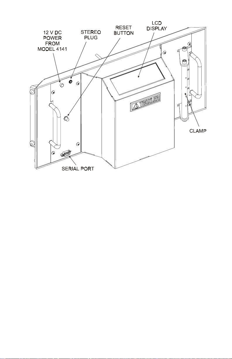
Figure 1. Model 3191 True Mold Angle Device
Model 3191 True Mold Angle Device 5
Page 10

SETUP AND OPERATION
This section describes how to use the TMA to monitor the gyration
angle during the compaction of a hot mix asphalt specimen.
1. Prepare the asphalt specimen as described on page 4–3 of the
Model 4141 Manual of Operation and Instruction.
2. Place the loaded mold into the Model 4141 compaction
chamber.
3. Lift the TMA into place. Hook the fixed (left) end of the TMA
around the left frame rail of the Model 4141.
4. Squeeze the spring-loaded clamp on the right end of the TMA,
and push the TMA against the compactor’s right frame rail.
Release the clamp to secure the TMA in place.
NOTE
Ensure that the TMA does not rest on the compactor
table.
5. Connect the 12 V dc and stereo cables from the TMA (see
Figure 1) to the appropriate connectors on the Model 4141 as
shown in Figure 2.
6. If using the True Mold Angle software to upload angle data to a
computer, connect the serial cable from the TMA to a serial port
on the computer. Refer to page 8 for instructions on installing,
starting, and using the software.
7. Compact the specimen as described on page 4–5 of the Model
4141 Manual of Operation and Instruction. During the
compaction process, the TMA displays the maximum,
minimum, and average measured mold angle, as well as the
standard deviation of the measurements. This information is
updated each gyration.
6
Page 11

NOTE
When processing an asphalt specimen, the average mold
angle should be between 1.23° and 1.27°.
NOTE
If excursion data is to be downloaded from the TMA to
a computer, do not disconnect the 12 V dc and stereo
cables from the compactor.
8. To remove the TMA from the compactor, disconnect the 12 V
dc and stereo cables from the Model 4141. Squeeze the springloaded clamp on the right end of the TMA, and lift the TMA
from the compactor.
STEREO
PLUG
12 V DC
POWER
TO TM A
DEVICE
Figure 2. TMA Connections on the Model 4141
Model 3191 True Mold Angle Device 7
Page 12

TRUE MOLD ANGLE SOFTWARE
During a compaction cycle, the TMA measures the excursions of its
upper and lower probes and uses these values to determine the
gyration angle. Starting with the third gyration of the cycle, the
TMA stores the excursion values and resulting angle for each
gyration.
The True Mold Angle software supplied with the TMA is used to
upload and store the excursion and angle data on a computer. The
data is stored in a comma-delimited format, as shown in Figure 3.
The following sections provide instructions on the installation,
setup, and use of the True Mold Angle software.
3,1.249,.000,6.092,.000
4,1.288,3.480,9.760,.000
5,1.286,3.476,9.748,.000
6,1.286,3.476,9.748,.000
7,1.284,3.480,9.744,.000
8,1.283,3.480,9.736,.000
9,1.284,3.480,9.740,.000
10,1.280,3.480,9.724,.000
11,1.279,3.488,9.728,.000
12,1.279,3.484,9.724,.000
13,1.279,3.484,9.724,.000
14,1.279,3.484,9.724,.000
15,1.278,3.484,9.716,.000
16,1.279,3.484,9.720,.000
17,1.279,3.484,9.724,.000
18,1.279,3.488,9.724,.000
19,1.277,3.488,9.716,.000
20,1.277,3.488,9.716,.000
21,1.278,3.488,9.720,.000
22,1.276,3.492,9.716,.000
23,1.276,3.492,9.716,.000
24,1.275,3.492,9.712,.000
25,1.277,3.492,9.720,.000
•
•
•
Figure 3. Sample Data from TMA
8
Page 13

SOFTWARE INSTALLATION
To install the True Mold Ang le softwar e:
1. Insert the True Mold Angle CD-ROM into the computer’s
CD-ROM drive.
2. From the Windows 95/98 desktop, click on the Start button in
the taskbar.
3. Select R
4. Type d:tmainstall.exe (where d: is the letter designation of
the CD-ROM drive) and then press the 〈Enter〉 key or click on
the OK button. Follow the instructions on the screen.
5. The installation program adds a Troxler group to the Programs
menu, with the program items: TMA and Uninstall TMA. The
installation program also places a shortcut icon for the TMA
application on the Windows desktop.
un. The dialog box shown in Figure 4 is displayed.
Figure 4. Installing the True Mold Angle Software
Model 3191 True Mold Angle Device 9
Page 14

STARTING THE TRUE MOLD ANGLE SOFTWARE
To start the True Mold Angle software, double-click on the TMA
icon on the Windows 95/98 desktop or click on the Start button,
select the P
TMA menu item. The software briefly displays a copyright screen
while loading. Upon completion, the software displays the Main
Menu shown in Figure 5.
rograms menu and the Troxler folder, and select the
Figure 5. True Mold Angle Software Main Menu
10
Page 15
UPLOADING DATA
The True Mold Angle software can upload excursion data from the
TMA into the computer either in real-time (during a compaction
cycle) or after a compaction cycle is complete.
NOTE
The TMA stores only the angle data from the most
recent compaction cycle. This data is available for
uploading at any time until a new compaction cycle is
begun or power has been removed from the TMA.
Uploading Data During Compaction
To acquire data from the TMA during a compaction cycle:
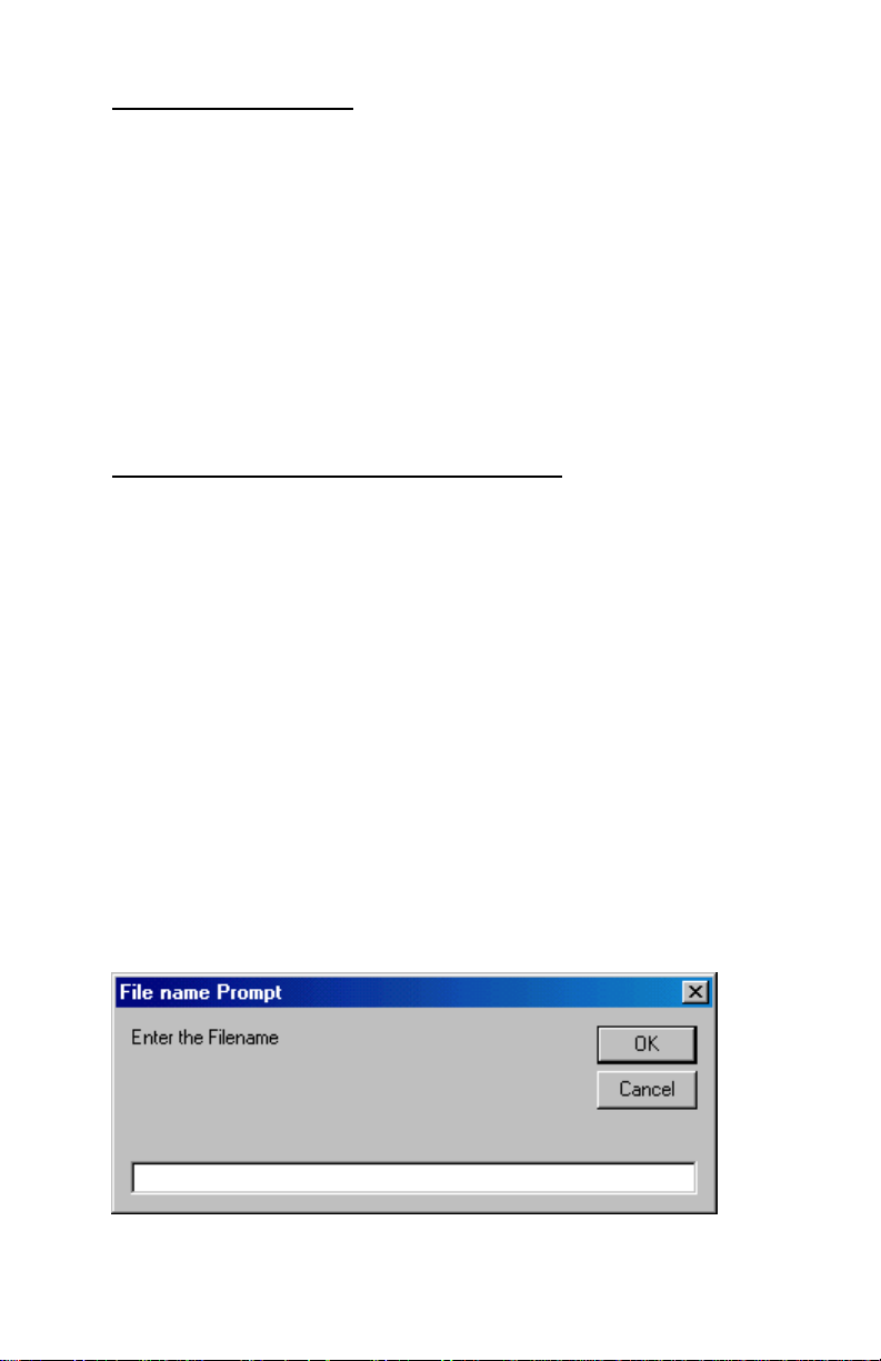
1. Click the Start button on the Main Menu. The software
requests a file name as shown in Figure 6.
2. Enter a filename, followed by the extension .txt, but do not press
the 〈Enter〉 key or click on the OK button.
3. Follow the directions on page 6 for operating the TMA while
compacting the specimen. After the compactor has begun
gyrating, press the 〈Enter〉 key or click on the OK button.
4. The command line at the bottom of the Main Menu displays
Initializing…, then Waiting for data… During the
compaction cycle, the software uploads excursion data from the
TMA and writes this data into the filename entered in step 2.
Figure 6. File Name Prompt
Model 3191 True Mold Angle Device 11
Page 16

Uploading Stored Data
NOTE
The TMA stores only the angle data from the most
recent compaction cycle. This data is available for
uploading at any time until a new compaction cycle is
begun or power has been removed from the TMA.
To upload the excursion data stored in the TMA from the most
recent compaction cycle:
1. Click the Upload button. The software requests a file name as
shown in Figure 6.
2. Enter a filename, followed by the extension .txt, and then press
the 〈Enter〉 key or click on the OK button.
3. The command line at the bottom of the Main Menu displays
Initializing…, then Collecting data… Please wait. The
software uploads the angle data from the TMA and writes this
data into the filename entered in step 2 above.
12
Page 17

REPLACEMENT PARTS
Match the reference number (Ref #) shown below with the correct
part in Figure 7 on the following page.
ITEM BIN NO. DESCRIPTION QTY.
1 002492 STEREO JACK SOCKET 1
2 104663 SMALL TROXLER LOGO PLATE 1
3 107692 CABLE, LCD 1
4 108555 LOGIC PROBE, TMA, 319X 2
5 108835 LABEL, TRUE MOLD ANGLE 1
6 109550 ELECT. BOARD ASSY, TMA: 3191,1,2 1
7 109697 ANGLE SERIAL CABLE ASSY 1
8 109798 LOGIC PROBE BRACKET, TMA: 319X 1
9 109802 CLAMP PIVOT MOUNT, TMA: 3191 4
10 109804 COVER ASSEMBLY, TMA: 3191,1 1
11 109805 CROSSBAR, TMA: 3191,2 2
12 109807 RIGHT SIDE COVER, TMA: 3191 1
13 109809 PIVOT BAR, TMA: 3191,2 1
14 109822 LEFT SIDE COVER, TMA: 3191 1
15 109824 ALUMINUM HANDLE, TMA: 3191,1,2 2
16 109833 DIAL INDICATOR EXT, 3/16 x 2-1/4 2
17 109834 COIL SPRING, RHW, TMA: 3191,2 4
18 109852 DISPLAY BRACKET, TMA: 3191,1 1
19 109853 ELECTRONICS BRACKET, TMA: 3191,1 1
20 109854 RUBBER BUMPER, TMA: 3191,2 8
21 109855 BACKPLATE ASSEMBLY, TMA, 3191 1
22 109858 DELRIN WASHER, TMA: 3191, 2 4
23 109859 CLAMP ARM, TMA: 3191 2
24 109911 CABLE ASSY POWER, RESET 1
25 000001-0200 LOCKWASHER #2 INT TOOTH SS 4
26 000061-1000 #2 HEX NUT SS 4
27 000106-1401 SCREW, 2-56 x .375 PHIL HD, SS 4
28 000406-4801 SCREW, 8-32 x .375 SHCS, SS 17
29 000406-4901 SCREW, 8-32 x .375 BHCS, SS 8
30 000420-4801 SCREW 8-32 X 1-1/4 SHCS SS 4
31 000806-4801 SCREW, 1/4-20 x .375 SHCS, SS 4
32 000812-4801 SCREW, 1/4-20 x .750 SHCS, SS 2
33 100-0003 HARDWARE KIT 1
34 108192-3191 LCD DISPLAY ASSY, TMA: 3191,1,2 1
35 27-5050 PUSH NUT FLAT-ROUND 3/8 OD 2
36 7607-1000 PUSH BUTTON BOOT 1
37 910-0434 #2 ROUND SPACER, 125", PLASTIC 4
Model 3191 True Mold Angle Device 13
Page 18
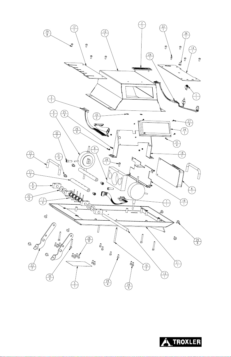
Figure 7. TMA Assembly Drawing
14
Page 19

RETURNING PARTS FOR SERVICE
Items returned for service must be accompanied by an RGA
(Returned Goods Authorization) number, and a description of the
instrument and its problem. This information is used by Troxler
shipping and service personnel to expedite the repair work.
To obtain an RGA number, please call or fax Troxler headquarters
at Research Triangle Park, or one of the branch offices with your
request (see list on page iii).
Please have the following information available when requesting an
RGA number:
• Unit (or part) model and serial number.
• Part number/serial number (if applicable).
• Is the unit (part) still under warranty?
• Problem or difficulty you are having with the unit.
• Shipment method to Troxler and for return shipment.
• Shipping and billing address (not P.O. Box) – street address and
zip.
• Phone number/contact (for questions from Troxler).
• Will estimate be required prior to performing any work on the
part?
• Payment method: credit card, account number, or purchase
order number. All government agencies (city, county, state,
and federal) must
To prevent order duplication, if an order has been
placed by telephone, please write “Confirming Order”
on any follow-up written requests.
Model 3191 True Mold Angle Device 15
send purchase order numbers.
NOTE
Page 20

SPECIFICATIONS
ENVIRONMENTAL CONDITIONS
Ambient Storage –55 to 85 °C
Temperature (–67 to 185 °F)
Ambient Operating 10 to 50 °C
Temperature (50 to 122 °F)
Altitude Rating 2000 meters maximum
Humidity 92% maximum
ELECTRICAL SPECIFICATIONS
Power Requirements 12 V dc (supplied by the Model
4141 Gyratory Compactor)
Serial Port: 9-pin male D-subminiature
connector
MECHANICAL SPECIFICATIONS
Size, Unit with 61L × 25W × 43H cm
Transport Case 24L × 10W × 17H in
Weight 3.6 kg (8lb)
Shipping Weight, 6.4 kg (14 lb)
Unit with Packaging
16
 Loading...