

Page 1

MODEL RL5000XP
PC-basED aTM
INsTaLLaTION GUIDE
VERSION 1.0
TDN 07102-00058 Oct 31 2008
CORPORaTE HEaDqUaRTERs: RMa (RETURN MaTERIaL aUTHORIza-
TION)
RETURN aDDREss:
522 E. Railroad Street 21405 Avenue “B”
Long Beach, MS 39560 Long Beach, MS 39560
Phone: (228) 868-1317
Fax: (228) 868-0437
COPYRIGHT NOTICE
© 2006 Delaware Capital Formation, Inc. All Rights Reserved. TRITON, TRITON
WHERE MONEY COMES FROM, TRITON WAVES, DOVER and the DOVER logo
are registered trademarks of Delaware Capital Formation, Inc., a wholly-owned subsidiary of Dover Corporation.
Page 2

RL5000XP INsTaLLaTION GUIDE
WHaT’s IN THIs INsTaLLaTION GUIDE
This Installation Guide gives step-by-step procedures for completing the physical
installation of a Triton RL5000XP. This guide covers cabinet and dispenser installation (if applicable) for RL5000XP units equipped with an NMD-100 dispensing
mechanism. The Installation Guide is divided into the following sections:
COMPLIaNCE NOTIfICaTIONs.
aTM INsTaLLaTION fOR aCCEssIbILITy. Describes the basic Americans
with Disabilities Act (ADA) requirements for ATM location and access.
Note: These are the general requirements that should be applicable to most
installation locations. Please verify the specic requirements with the state
where the ATM is to be installed prior to installation. For state contact
information, you may call the ADA information line at 1-800-514-0301.
aTM ENvIRONMENTaL PRECaUTION s CHECkLIsT. Describes the general
environmental precautions considered when installing the ATM. To help
ensure proper operation of the ATM, ensure the environmental criteria listed
in this checklist are met.
CabINET INsTaLLaTION - sTaNDaRD aNCHORs. Describes how to install the
ATM cabinet using standard (steel) anchor bolts.
CabINET INsTaLLaTION - CHEMICaL bOLTs. Describes how to install the ATM
cabinet using a chemical anchoring process. Note that to install the cabinet
according to these instructions you must purchase the optional chemical
anchor install kit (Part Number 06200-00060).
POWER aND COMMUNICaTION. Describes how to connect the ATM to the
facility power and Ethernet connections.
DIsPENsING MECHaNIsM INsTaLLaTION. Describes how to install the NMD-
100 dispensing mechanism into the ATM security cabinet.
2
Page 3
RL5000XP INsTaLLaTION GUIDE
DIsCLaIMER
The manufacturer of the Automated Teller Machine (ATM) product(s) described
herein makes no representations or warranties, either expressed or implied, by or
with respect to anything in this manual, and shall not be liable for any implied
warranties of tness for a particular purpose or for any indirect, special, or
consequential damages. Information in this document is subject to change without
notice and does not represent a commitment on the part of the manufacturer.
** CAUTION **
Changes or modications not expressly approved by Triton
Systems could void the regulatory compliance approval
and the warranty. Use of this product in a manner other
than those described in this manual may result in personal
injury!
fEDERaL COMMUNICaTIONs COMMIssION (fCC) COMPLIaNCE
Statement of Compliance: This equipment complies with Part 68 of the FCC
rules. Located in the control area of the Automated Teller Machine (ATM)
is the product label. This label lists the FCC registration number and ringer
equivalence number of the unit. If requested, this information must be provided
to the telephone company. USCO/FIC Codes: When ordering service from the
telephone company for the RL5000XP ATM, the following information should
be supplied:
Universal Service Order Code (USOC): RJ-11C
The Facility Interface Code (FIC): 02LS2
Plug and Jack: The plug and jack used to connect this equipment to premise wiring
and telephone network must comply with the applicable FCC Part 68 rules and
requirements adopted by ACTA. A compliant telephone cord and modular plug
is provided with this product. The telephone cord is designed to be connected
to a compatible modular jack that is also compliant.
Ringer Equivalent Number (REN): The REN is used to determine the number
of the devices that may be connected to a telephone line. Excessive RENs on a
telephone line may result in the devices not ringing in response to an incoming
call. In most but not all areas, the sum of the RENs should not exceed ve (5). To
be certain of the number devices that may be connected to a line, as determined
by the local RENs, contact the local telephone company.
3
Page 4

RL5000XP INsTaLLaTION GUIDE
Harm to the Network: If the RL5000XP ATM causes harm to the telephone
network, the telephone company will notify the customer that a temporary
discontinuous of service may be required. If advanced notice is not possible,
the telephone company will notify the customer as soon as possible. You will be
advised of your right to le a complaint with the FCC if you believe it’s necessary.
Notication of Changes in Telephone Company Equipment: The telephone
company may make changes in its facilities, equipment, operations, or procedures
that could affect the operation of the equipment. If this happens, the telephone
company will provide advanced notice in order for you to make necessary
modications to maintain uninterrupted service.
Repairs and Returns: If telecom compatibility trouble is experienced with the
RL5000XP ATM, you may contact for repairs and warranty information: Triton
at 1-228-868-1317
Triton Systems of Delaware, Inc.
522 East Railroad Street
Long Beach, MS 39560
If the equipment is causing harm to the network, the telephone company may
request that you disconnect the equipment until the problem is resolved. Repairs
should be made only by qualied factory representatives.
Party Lines: The RL5000
XP
ATM must not be used on party lines.
Alarm Equipment: The RL5000XP ATM should have its own dedicated phone
line. Do not install the RL5000XP on the same line as alarm equipment.
Electrical Safety Advisory: Telephone companies report that electrical surges,
typically lightening transients, are very destructive to customer equipment
connected to AC power sources. This has been identied as a major nationwide
problem. A commercially available, power surge suppressor, is recommended for
use with the RL5000XP to minimize damage in the event of an electrical surge.
CaNaDIaN IC COMPLIaNCE
NOTICE:
The Industry Canada label identies certied equipment. This certication means
that the equipment meets telecommunications network protective, operational
and safety requirements as prescribed in the appropriate terminal equipment
technical requirements document(s). The department does not guarantee the
equipment will operate to the user’s satisfaction.
4
Page 5

RL5000
XP
INsTaLLaTION GUIDE
Before installing this equipment, users should ensure that it is permissible to
be connected to the facilities of the local telecommunications company. The
equipment must also be installed using an acceptable method of connection. The
customer should be aware that compliance with the above conditions may not
prevent degradation of service in some situations.
Repairs to certied equipment should be coordinated by a representative designated by the supplier. Any repairs or alterations made by the user to this equipment or equipment malfunctions may give the telecommunications company
cause to request the user to disconnect the equipment.
Users should ensure for their own protection that the electrical ground connections
of the power utility, telephone lines and internal metallic water pipe system, if
present, are connected together. This precaution may be particularly important
in rural areas. Caution: Users should not attempt to make such connections
themselves, but should contact the appropriate electric inspection authority or
electrician as appropriate.
NOTICE:
The Ringer Equivalence Number (REN) assigned to each terminal device
provides an indication of the maximum number of terminals allowed to be connected to a telephone interface. The termination on an interface may consist of
any combination of devices subject only to the requirement that the sum of the
RENs of all the devices does not exceed 5.
avIs:
L’étiquette d’Industrie Canada identic le matériel homologué. Cette étiquette
certie que le matériel est conforme aux normes de protection, d’exploitation et
de sécurité des réseaux de télécommunications, comme le prescrivent les documents concernant les exigences techniques relatives au matériel terminal. Le
Ministère n’assure toutefois pas que le matériel fonctionnera à la satisfaction
de l’utilisateur.
Avant d’installer ce matériel, l’utilisateur doit s’assurer qu’il est permis de le
raccorder aux installations de 1’entreprise locale de télécommunication. Le
matériel doit également être installé en suivant une méthode acceptée de raccordement. L’abonné ne doit pas oublier qu’il est possible que la comformité
aux conditions énoncées ci-dessus n’empêche pas la dégradation du service dans
certaines situations.
Les réparations de matériel homologué doivent être coordonnées par un représentant désigné par le fournisseur. L’entreprise de télécommunications peut demander
à I’utilisateur de débrancher un appareil à la suite de réparations ou de modications effectuées par l’utilisateur ou à cause de mauvais fonctionnement.
5
Page 6

RL5000XP INsTaLLaTION GUIDE
Pour sa propre protection, l’utilisateur doit s’assurer que tous les ls de mise à la
terre de la source d’énergie électrique, des lignes téléphoniques et des canalisa-
tions d’eau métalliques, s’ y en a, sont raccordés ensemble. Cette précaution est
particulièrement importante dans les régions rurales. Avertissement: L’utilisateur
ne doit pas tenter de faire ces raccordements lui-même; il doit avoir recours à an
service d’inspection des installations électriques, ou à un électricien, selon le cas.
avIs:
L’indice d’équivalence de la sonnerie (IES) assigné à chaque dispositif terminal indique le nombre maximal de terminaux qui peuvent étre raccordés à une
interface. La terminaison d’une interface téléphonique peut consister en une
combinaison de quelques dispositifs, à la seule condition que la somme d’indices
d’équivalence de la sonnerie de tous les dispositifs n’exède pas 5.
UNITED kINGDOM
This equipment has been approved in accordance with Council Decision 98/482/
EC for pan-European single terminal connection to the Public Switched Telephone Network (PSTN). However, due to differences between the individual
PSTNs provided in the different countries, the approval does not, of itself,
give unconditional assurance of successful operation on every PSTN network
termination point. In the event of problems, contact your equipment supplier
in the rst instance. This unit uses only Dual-Tone Multi-Frequency (DTMF)
address signaling.
EMIssIONs (EMI)
Us REqUIREMENTs
This device complies with Part 15 of the FCC rules. Operation is subject to the
following two (2) conditions:
1) This device may not cause harmful interference.
2) This device must accept any interference received, including interference that
may cause undesired operation.
NOTE:
This equipment has been tested and found to comply with the limits for a Class
A digital device pursuant to Part 15 of FCC Rules. These limits are designed to
provide reasonable protection against harmful interference when the equipment is
operated in a commercial environment. This equipment generates, uses, and can
radiate radio frequency energy and, if not installed and used in accordance with
the instruction manual may cause harmful interference to radio communications.
Operation of this equipment in a residential area is likely to
6
Page 7

RL5000XP INsTaLLaTION GUIDE
cause harmful interference in which case the user will be required to correct
the interference at his own expense. Changes or modications to this unit not
expressly approved by the party responsible for compliance could void the user’s
authority to operate the equipment.
CaNaDIaN REqUIREMENTs
This digital apparatus does not exceed the Class A limits for radio noise emissions
from digital apparatus set in the Radio Interference Regulations of the Canadian
Department of Communications. This Class A digital apparatus complies with
Canadian ICES-003.
Le present appareil numerique n’emet pas de bruits radioelectriques depassant
les limites applicables aux appareils numeriques de la Class A prescrites dans
le Reglement sur le brouillage radioelectrique edicte par le ministere des
Communications du Canada. Cet appareil numerique de la classe A est conforme
a la norme NMB-003 Canada.
Uk REqUIREMENTs
WaRNING:
This is a Class A product. In a domestic environment, this product may cause
radio interference in which case the user may be required to take adequate
measures.
7
Page 8

RL5000XP INsTaLLaTION GUIDE
THIs PaGE INTENTIONaLLy LEfT bLaNk
8
Page 9

aTM INsTaLLaTION fOR aCCEssIbILITy
9
Page 10

RL5000XP INsTaLLaTION GUIDE
aTM INsTaLLaTION fOR aC-
CEssIbILITy
1. This document supercedes all
other information provided by
Triton for ATM installation for
accessibility.
2. Information provided in this manual is based on federal guidelines
(ADA Accessibility Guidelines
for Buildings and Facilities –
ADAAG), as amended through
January 1998. You should verify
it has not been amended. States
may also have accessibility codes.
These codes may be more restrictive than the federal guidelines.
Please verify this with the state
where the ATM is to be installed
prior to installation. For state
contact information, you may
call the ADA information line at
1-800-514-0301.
3. For countries other than the US,
please use the guidelines for accessibility for that country.
4.34 Automated Teller Machines.
4.34.1 General. Each automated
teller machine required to be
accessible by 4.1.3 (Accessible
Buildings:New Construction)
shall be on an accessible route
and shall comply with 4.34 (Au-
tomated Teller Machines).
4.34.2 Clear Floor Spa ce. The
automated teller machine shall be
located so that clear oor space
complying with 4.2.4 (Clear
Floor or Ground Space for
Wheelchairs) is provided to al-
low a person using a wheelchair
to make a forward approach, a
parallel approach, or both to the
machine.
4.34.3 Reach Ranges.
(1) Forward Approach Only. If
only a forward approach is possible,
operable parts of all controls shall be
placed within the forward reach range
specied in 4.2.5 (Forward Reach).
4. A complete copy of the ADAAG
referred to here can be found at
http://www.access-board.gov.
Included in this document is
the section of the ADAAG spe-
cically for ATMs. For additional
information on oor surfaces and
othe r ADAAG requiremen ts,
please see the complete specication.
(2) Parallel Approach Only. If only
a parallel approach is possible, operable parts of controls shall be placed
as follows:
(a) Reach Depth Not More Than
10 inches (255 mm). Where the reach
depth to the operable parts of all controls as measured from the vertical
plane perpendicular to the edge of the
unobstructed clear oor space at the
farthest protrusion of the automated
teller machine or surround is not
more than 10 inches (255 mm), the
maximum height above the nished
oor or grade shall be 54 inches (1370
mm).
10
Page 11
aTM INsTaLLaTION fOR aCCEssIbILITy
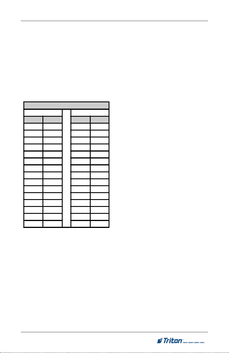
ACCESSIBILITY SPECIFICATIONS
REACH DEPTH MAXIMUM HEIGHT
Inches Millime ters Inches Millimete rs
10 255 54 1370
11 280 53 1/2 1360
12 305 53 1345
13 330 52 1/2 1335
14 355 51 1/2 1310
15 380 51 1295
16 405 50 1/2 1285
17 430 50 1270
18 455 49 1/2 1255
19 485 49 1245
20 510 48 1/2 1230
21 535 47 1/2 1205
22 560 47 1195
23 585 46 1/2 1180
24 610 46 1170
(b) Reach Depth More Than 10
inches (255 mm). Where the reach
depth to the operable parts of any
control as measured from the vertical
plane perpendicular to the edge of the
unobstructed clear oor space at the
farthest protrusion of the automated
teller machine or surround is more
than 10 inches (255 mm), the maxi-
mum height above the nished oor
or grade shall be as follows:
EXCEPTION: Where a function
can be performed in a substantially
equivalent manner by using an alternate control, only one of the controls
needed to perform that function is
required to comply with this section.
If the controls are identied by tactile
markings, such markings shall be
provided on both controls.
4.34.4 Controls. Controls for user
activation shall comply with 4.27.4
(Operation).
4.34.5 Eq uipment for Persons
with Vision Impairments. Instructions and all information for use shall
be made accessible to and independently usable by persons with vision
impairments.
(20) Wh e r e au t o mated telle r
machines (ATMs) are provided, each
ATM shall comply with the requirements of 4.34 (Automated Teller
Machines) except where two or more
are provided at a location, then only
one must comply.
(3) F orwar d an d Pa rall e l Approach. If both a forward and parallel
approach are possible, operable parts
of controls shall be placed within at
least one of the reach ranges in paragraphs (1) or (2) of this section.
(4) Bins. Where bins are provided
for envelopes, waste paper, or other
purposes, at least one of each type provided shall comply with the applicable
reach ranges in paragraph (1), (2), or
(3) of this section.
EXCEPTION: Drive-up-only automated teller machines are not required
to comply with 4.27 (Controls and
Operating Mechanisms and 4.34.3
(Reach Ranges).
11
Page 12
RL5000XP INsTaLLaTION GUIDE
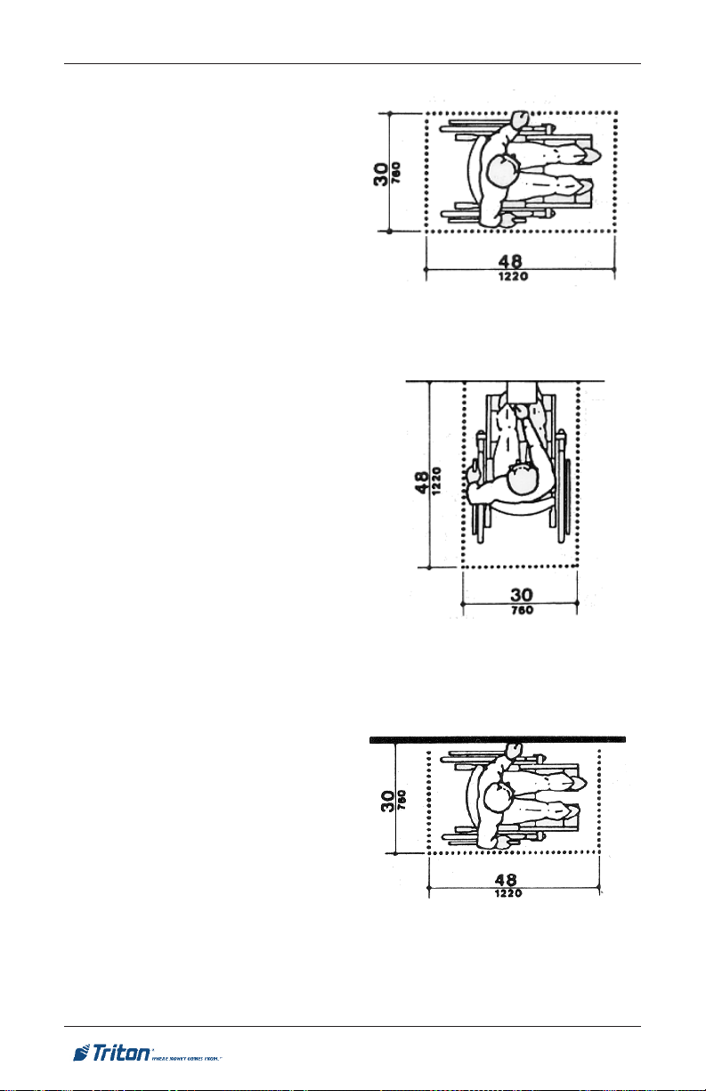
4.2.4 Clear Floor or Ground
Space for Wheelchairs.
4.2.4.1 Size and Approach. The
minimum clear oor or ground space
required to accommodate a single,
stationary wheelchair and occupant
is 30 inches by 48 inches (760 mm by
1220 mm) (see Fig. 4a). The minimum
clear oor or ground space for wheelchairs may be positioned for forward
or parallel approach to an object (see
Fig. 4b and 4c). Clear oor or ground
space for wheelchairs may be part of
the knee space required under some
objects.
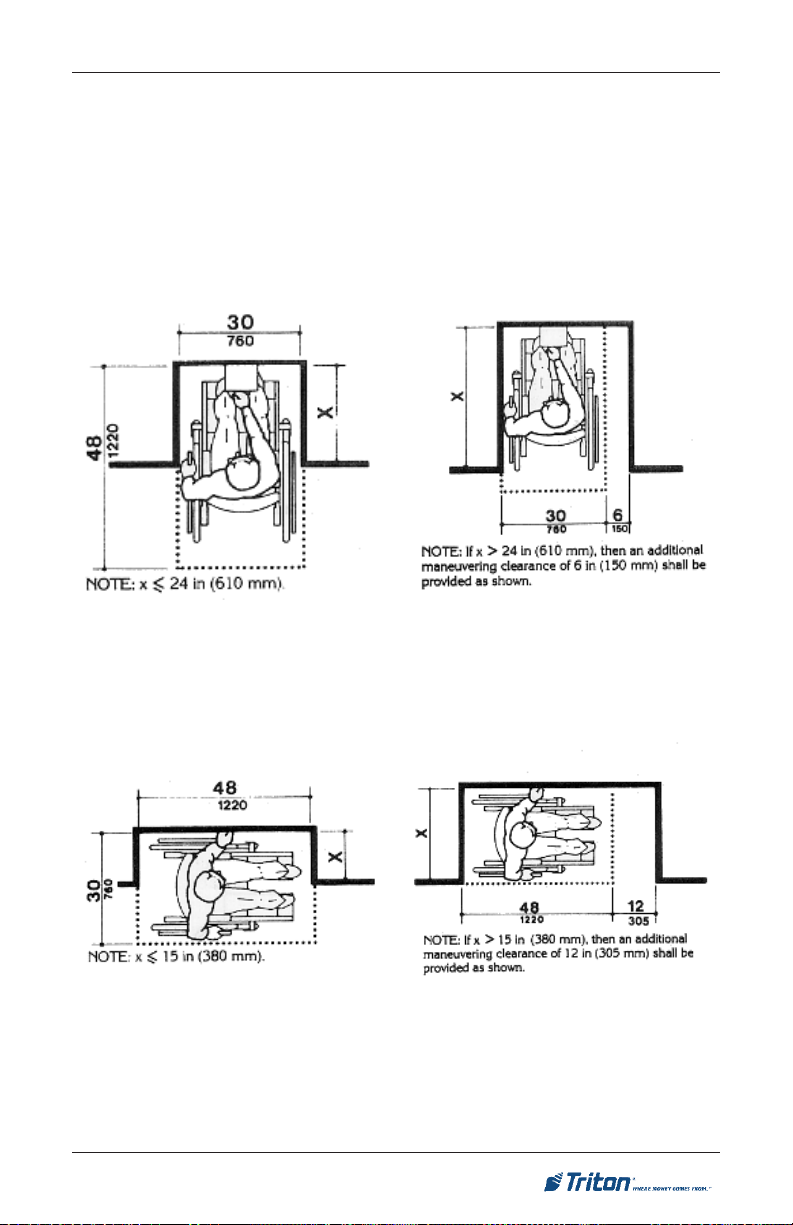
4.2.4.2 Relationship of Maneuvering Clearance to Wheelchair Spaces.
One full unobstructed side of the clear
oor or ground space for a wheelchair
shall adjoin or overlap an accessible
route or adjoin another wheelchair
clear oor space. If a clear oor space
is located in an alcove or otherwise
conned on all or part of three sides,
additional maneuvering clearances
shall be provided as shown in Fig. 4(d)
and 4(e).
4.2.4.3 Surfaces for Wheelchair
Spaces. Clear oor or ground spaces
for wheelchairs shall comply with 4.5.
Figure 4a. Clear oor space.
Figure 4b. Forward approach.
4.2.5 For w ard Re ach. If th e
clear oor space only allows forward
approach to an object, the maximum
high forward reach allowed shall be
48 inches (1220 mm) (see Fig. 5(a)).
The minimum low forward reach is 15
inches (380 mm). If the high forward
reach is over an obstruction, reach and
clearances shall be as shown in Fig.
5(b).
Figure 4c. Parallel approach.
12
Page 13
aTM INsTaLLaTION fOR aCCEssIbILITy
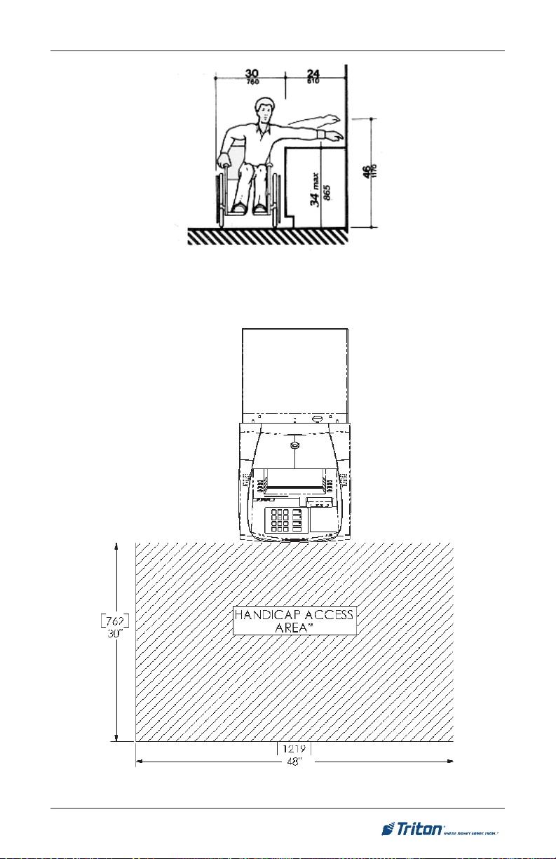
4.2.6 Side Reach. If the clear oor space allows parallel approach by a person
in a wheelchair, the maximum high side reach allowed shall be 54 inches (1370
mm) and the low side reach shall be no less than 9 inches (230 mm) above the
oor (Fig. 6(a) and 6(b)). If the side reach is over an obstruction, the reach and
clearances shall be as shown in Fig 6(c).
Figures 4d. Clear floor space in
alcoves.
For a front approach, where the depth
of the alcove is equal to or less than
24 inches (610 mm), the required clear
oor space is 30 inches by 48 inches
(760 mm by 1220 mm).
Figures 4e. Clear floor space in
alcove.
For a front approach, if the depth of
the alcove is greater than 24 inches
(610 mm), then in addition to the 30inch (760 mm) width, a maneuvering
clearance of 6 inches (150 mm) in
width is required.
For a side approach, where the depth
of the alcove is equal to or less than
15 inches (380 mm), the required clear
oor space is 30 inches by 48 inches
(760 mm by 1220 mm).
For a side approach, where the depth
of the alcove is greater than 15 inches
(380 mm), then in addition to the 48inch (1220 mm) length, an additional
maneuvering clearance of 12 inches
(350 mm) is required.
13
Page 14

RL5000XP INsTaLLaTION GUIDE
Figure 5a. Forward reach, unobstructed.
Figure 5b. Forward reach, obstructed.
Figure 6a. Parallel approach - side
reach.
Figure 6b. Parallel approach - high/
low side reach.
14
Page 15
aTM INsTaLLaTION fOR aCCEssIbILITy
Figure 6c. Side reach, obstructed.
RL5000XP ADA requirements.
15
Page 16

RL5000XP INsTaLLaTION GUIDE
THIs PaGE INTENTIONaLLy LEfT bLaNk
16
Page 17

aTM ENvIRONMENTaL PRECaUTIONs
CHECkLIsT
17
Page 18

aTM ENvIRONMENTaL PRECaUTIONs CHECkLIsT
When installing an ATM, some general environmental precautions
need to be considered. Evaluate the location where the ATM will be
installed. To help ensure proper operation of the ATM, ensure the
environmental criteria listed in this checklist are met.
TEMPERATURE/HUMIDITY
1. The ATM needs to be in an
en viron men tal ly- con troll ed
location, with no extreme uctu ations in temperature or
humidity.
Generally, these parameters
must fall within the following
ranges:
Temperature
• 10-40 Deg. C
• 50-104 Deg. F
Relative Humidity
• 20% - 80%
• (Non-Condensing)
AC POWER REQUIREMENTS
2. Ensure the following AC power
requirements are met:
Current (Max)
• 5.05A @ 120V
• 2.01A @ 240V
Voltage
• 90V - 136V @ 50/60 Hz
• 198V - 257V @ 50/60 Hz
Dedicated source. The ATM AC
power feed will be a dedicated line, to
which no other electrical devices are
connected. The ATM power line will
be wired for a single “duplex”-style
outlet and connected directly to the
AC service panel.
Isolated Ground. An equipment
grounding conductor that is insulated
from the conduit or raceway and all
other grounding points throughout
its entire length. The only points of
electrical connection will be at the
duplex outlet and service panel ends
of the line.
DEDICATED TELEPHONE
3. Ensure the following telephoneline requirements are met:
Dedicated line. The telephone line
servicing the ATM will not be a
“party” line or any other shared type
connection.
Proximity to Interference Sources.
The telephone line must not be in
close proximity to “noisy” devices
that could induce interference into the
ATM communications channel.
RF INTERFERENCE
Power Consumption (Idle)
• 2.0A @ 115 VAC at 60 Hz
• 1.0A @ 230 VAC at 50 Hz
Power Consumption (Max Load)
• 606 Watts @ 120V
• 482 Watts @ 240V
4. Ensure there are no devices
near the terminal that may
cause RF interference, such as:
TVs Coolers
Security Devices
Neon Signs
Devices with Compressors
18
Page 19

CabINET DIMENsIONs
19
Page 20

RL5000XP INsTaLLaTION GUIDE
Service Area Dimensions
Cabinet Dimensions (Side/Rear Views)
20
[ 610 ]
24”
Cable Feed
Through
Page 21

CabINET INsTaLLaTION
sTaNDaRD aNCHORs
21
Page 22

RL5000XP INsTaLLaTION GUIDE
PARTS SUPPL IED
4
1/2" x 4 1/4 " Sleeve-Ty pe
Anchor Bolts
4
1/2" Flat Washers for Anchor
Bolts
8
1/2" Nuts for Anchor
Bolts
1 Drilling Template
4
Leveling Feet (for Optional Use
with Business H ours Service
Cabinets).
REQUIRED TOOLS/EQUIPMENT
1
Torque Wrench, Adjustable to at least 60 Foot-Poun ds (or 3/4"
Ratchet Wrench).
1 Center Punch (or eq uivalent) for marking drilling p oints.
1
3/4" Socket (For Tightening Anchor Bolts)
1 Hammer
1 Large Flat Screwdriver 1 Bubb le Level
1
3/4" Heavy-Duty
(Professional-Grade)
Electric Hammer Drill.
1
1/4" and 1/2" C arbide-tipp ed
Masonry Drill Bits - at least 6"
long.
1 Safety Goggles 1
Ear Plugs or Ear Muffs
(hearing protection)
1 Back-Support Belt 1 Portable Vacuum Cleaner
UNPACK CASH DISPENSER
*IMPORTANT*
The RL5000XP is designed for
indoor installation only!
1. Carefully inspect the unit for
any shipping damage and report
any damage immediately to
the shipping company. Refer
to the warranty information
in the User or Service manual
(as applicable) for information
about reporting shipping
damage.
2. Remove the unit from the carton
by cutting the straps and removing
the top of the box.
3. Remove the loose packing
material from inside of the box.
4. Remove the silver key from the
white plastic bag attached to the
ATM wrapping.
UL LEVEL 1 CABINET
SAFETY
Level 1 cabinets are considerably heavier than Business
Hours cabinets! Exercise ex-
treme caution when moving
Level 1 cabinets! At least two
persons should work together to
move the cabinet into position
for mounting!
TOOL USE/SAFETY
Observe ALL safety precautions for operating hand and
power tools! Wear eye and ear
protection while operating the
electric drill! USE A BACK-
SUPPORT B E LT WHEN
LI FTING AND MOVING
THE ATM!
SELECTING THE
INSTALL ATI ON LOCATION
Choosing the right location for
your ATM is very important.
Security concerns suggest a
location that is away from any
door or external access point.
Ideally, the terminal should
be mounted as close to a back
wall as possible. For marketing
reasons, however, it may be
desirable to locate the terminal near the front where your
customers can easily locate it.
Wherever you decide to locate
the terminal, be sure to follow
the recommended procedures
for both mounting the terminal
and for removing cash when
the unit will be unattended.
22
Page 23

CabINET INsTaLLaTION - sTaNDaRD aNCHORs
5. Stand the unit up and walk it out
of the shipping carton.
6. Remove the wrapping from the
ATM.
7. Use the silver key to unlock both
the control panel and the fascia
door (which conceals the locking
mechanism) on the front of the
cabinet. Open the fascia door.
8. Turn the handle on the locking
mechanism to open the front
enclosure door. If the door is
locked see the sidebar on this
page for help in unlocking the
electronic lock.
9. Remove the packing material
from inside the bottom enclosure.
Next, remove the accessory kit;
open and inspect the contents.
Check the contents against the
enclosed packing list. Report
any mi ssing pa rts to Tr iton
immediately.
POWER OUTLET
ACCESSIBILITY
Whether you are installing a new
outlet or plan to use an existing
outlet to supply power to the ATM,
make sure the following requirements are met:
1. The outlet is located near the
cabinet.
UNLOCKING
ELECTRONIC
LOCKS
EL E C TR O N IC LO C K .
Upon arrival, the combination
of the lock should already
be prese t to 1-2-3 - 4-5-6.
To unlock, enter the preset
combination and check for
proper operation. After each
keypress, the lock will beep.
After the nal digit has been
entered, the lock will beep
twice and the open period
wil l begin. When a valid
combination has been entered,
the operator will
have approximately 3 seconds
to open the lock. To open the
lock, turn the dial clockwise.
After the lock is opened, the
door latch may be turned and
the safe opened.
2. The outlet is easily accessible.
3. Access to the outlet will not
be blocked once the cabinet
is installed!
23
Page 24

RL5000XP INsTaLLaTION GUIDE
MARK/DRILL MOUNTING
HOLES
CONCRETE STRENGTH
The oor at the installation location
should consist of commercial-grade
concrete measuring at least 2000
psi in compression strength. The
full effectiveness of the mounting
anchors depends upon meeting
this specication! Check with the
contractor/builder or owner of the
installation to verify that this re-
quirement can be satised.
Ma rk the locatio n of the cab ine t
mounting holes on the concrete oor.
This is accomplished as described
below:
1. Move the ATM to the location
where it will be installed.
Open the cabinet door at least
90° degrees to improve access.
Locate the four anchor-bolt holes
(cutouts) in the bottom of the
cabinet. Use a felt-tip pen or
other marker to carefully mark
the center of each of these four
holes on the oor; these marks
will serve as guides for the anchor
bolt holes that will be drilled in
the next step. Move the ATM
aside to provide clear access to
the mounting hole marks. Center
punch each mark to help align the
drill bit.
2. Use a 1/4” diameter carbidetipped masonry bit to drill four
pilot holes at the drilling points
marked in the previous step. Drill
the pilot holes approximately 1/2”
deep into the oor. These holes
will help guide the 1/2” masonry
bit that will be used to drill the
anchor-bolt holes in the next step.
Drill anchor holes
3. Use a 1/2” diameter carbide-tipped
masonry bit to drill four holes at
least 2 3/4” deep into the oor. Be
sure to take into account the depth
of any oor covering, such as tile
or vinyl when gauging the depth
of the anchor holes. Make sure the
holes are drilled at least
2 3/4” into the concrete oor.
4. Use a portable vacuum cleaner to
remove any dust or debris that may
have fallen into the holes during
the drilling process.
24
Page 25

CabINET INsTaLLaTION - sTaNDaRD aNCHORs
BOLT CABINET TO FLOOR
1. Move the ATM into position for
mounting by aligning the base
over the four holes drilled in the
previous procedure.
2. Place an anchor bolt through the
cabinet base and into one of the
mounting holes. Use a ball peen
hammer to tap the bolt completely
into the hole.
IMPORTANT: If the anchor
bolt “falls” into the hole without
needing to be tapped in, the hole
is too large! The mounting-hole
pattern will have to be moved
and redrilled using smaller holes
as necessary to achieve a snug
t.
3. Place a at washer on the anchor
bolt followed by a 1/2” nut.
LEVEL FLOORING
REQUIREMENT
It is very important that the
ATM cabinet be located on at,
level ooring! If the oor is not
at and level the cabinet bottom
and/or walls may become distorted when the mounting bolts
are tightened down! This could
prevent the security vault door
from closing!
Sleeve-type anchor bolt
4. Repeat Steps 2 and 3 for the
remaining anchor bolts.
Place anchor bolts in mounting
holes.
Tap anchor bolts into mounting
holes.
25
Page 26

RL5000XP INsTaLLaTION GUIDE
5. Ensure the cabinet is as level
as possibl e give n the f loor
conditions. Use a bubble level
to verify this. If a bubble-level is
not available, the cabinet can be
“rocked” gently from front-toback and side-to-side to check the
need for leveling.
6. Use a torque wrench and 3/4”
socket to tighten each nut to a
torque setting of 60 foot-pounds
(require d t o establish t h e
maximum pull-out strength of
the anchors). If a torque wrench
is not available, use a ratchet
wrench and 3/4” socket to tighten
the nuts three full turns beyond
hand tight.
7. O n c e all a n cho r bolts a r e
tightened, close the door of the
cabinet to ensure that the door
opens and closes without binding.
If the door does bind, it may be
necessary to relocate the cabinet
to an area with a at level oor!
If a Business Hours cabinet
was installed with leveling feet,
the feet may have caused the
warping of the cabinet bottom
under pressure of the mounting
bolts.
LEVELING FEET
Follow these steps to adjust the
leveling feet:
1. Once the cabinet is in the
final mounting position,
use a 1/4” (6mm) nutdriver
or socket set to adjust the
leveling bolts. DO NOT
extend the feet any further
than necessary to level
the cabinet! Use a bubble
level, if available, to verify
the cabinet is level.
2. After the mounting bolts
hav e been t i ght e n e d ,
ensure the cabinet door
can close without binding.
It may be necessary to
adjust the tightening of
th e mount ing bolts to
enable the door to close
without binding.
If leveling feet are used, the
cabinet bottom may experience warping or bending when
the mounting bolts are tightened down! This may prevent
the cabinet door from closing
cleanly!
8. Onc e the nuts ar e tighten ed
as specified in Step 6 and the
door operates without binding
as veried in Step 7, install a
second nut on each bolt and
tighten down rmly.
9. If the dispenser tray was removed
to facilitate cabinet installation,
replace it at this time.
26
Page 27

CabINET INsTaLLaTION - sTaNDaRD aNCHORs
10. The physical installation of the ATM cabinet is complete.
Fig. 5. Tighten bolts with torque
wrench.
Fig. 6. Second nut installed.
Fig. 7. Mounting hole drill template (Not to scale).
27
Page 28

RL5000XP INsTaLLaTION GUIDE
THIs PaGE INTENTIONaLLy LEfT bLaNk
28
Page 29

CabINET INsTaLLaTION
CHEMICaL aNCHORs
21
Page 30

RL5000
PARTS SUPPLIED
4
Chemical Anchor
capsules (02316-00002)
4
Threaded chisel-point rods,
M12 x 1.75 (02302-00006 )
8
Hex nuts, M12 x 1.75
(02301-00015)
4 Washers (02309-00014)
REQUIRED TOOLS/EQUIPMENT
1
Adjustable Crescent Wrench, or Ra tchet Wrench with 18 mm
(3/4-inch) socket
1
Center Punch (for
marking drilling points)
1
Wire Brush (for cleaning
mounting holes)
1 Large Flat Screwdriver 1 Bubble Level
1
Heavy-Duty (ProfessionalGrade) Electric Hammer
Drill.
1
6 mm (1/4-inch) and 15 mm
(9/16-inch) Carbide-tipped
Masonry Drill Bits - at least
15 cm (6-inches) long
1 Safety Goggles 1
Ear Plugs or E ar Muffs
(hearing protection)
1 Back-Support Belt 1
Portable Vacuum Cleaner or
Blower (to remove du st and
debris from mounting holes)
XP
INsTaLLaTION GUIDE
**IMPORTANT**
The following procedure applies to
the OPTIONAL Chemical anchor
install kit (06200-00060 - must
purchase)
UNPACK CASH DISPENSER
**IMPORTANT**
The RL5000XP is designed for
indoor installation only!
1. Carefully inspect the unit for
any shipping damage and report
any damage immediately to
the shipping company. Refer
to the warranty information
in the User or Service manual
(as applicable) for information
about reporting shipping
damage.
2. Remove the unit from the carton
by cutting the straps and removing
the top of the box.
UL LEVEL 1 CABINET
SAFETY
Level 1 cabinets are considerably heavier than Business
Hours cabinets! Exercise ex-
treme caution when moving
Level 1 cabinets! At least two
persons should work together to
move the cabinet into position
for mounting!
TOOL USE/SAFETY
Observe ALL safety precautions for operating hand and
power tools! Wear eye and ear
protection while operating the
electric drill! USE A BACK-
SUPPORT B E LT WHEN
LI FTING AND MOVING
THE ATM!
SELECTING THE
INSTALL ATI ON LOCATION
Choosing the right location for
your ATM is very important.
Security concerns suggest a
location that is away from any
door or external access point.
Ideally, the terminal should
be mounted as close to a back
wall as possible. For marketing
reasons, however, it may be
desirable to locate the terminal near the front where your
customers can easily locate it.
Wherever you decide to locate
the terminal, be sure to follow
the recommended procedures
for both mounting the terminal
and for removing cash when
the unit will be unattended.
30
Page 31

CabINET INsTaLLaTION - CHEMICaL aNCHORs
3. Remove the packing material
from inside of the box.
4. Remove the silver key from the
white plastic bag attached to the
ATM wrapping.
5. Stand the unit up and walk it out
of the shipping carton.
6. Remove the wrapping from the
ATM.
7. Use the silver-colored key to
unlock both the control panel and
the fascia door (which conceals
the locking mechanism) on the
front of the cabinet. Open the
fascia door.
8. Turn the handle on the locking
mechanism to open the front
enclosure door. If the door is
locked, see the sidebar on this
page for help in unlocking the
electronic lock.
9. Remove the packing material
from inside the bottom enclosure.
Next, remove the accessory kit;
open and inspect the contents.
Check the contents against the
enclosed packing list. Report
any mi ssing pa rts to Tr iton
immediately.
UNLOCKING
ELECTRONIC
LOCKS
EL E C TR O N IC LO C K .
Upon arrival, the combination
of the lock should already
be prese t to 1-2-3 - 4-5-6.
To unlock, enter the preset
combination and check for
proper operation. After each
keypress, the lock will beep.
After the nal digit has been
entered, the lock will beep
twice and the open period
wil l begin. When a valid
combination has been entered,
the operator will
have approximately 3 seconds
to open the lock. To open the
lock, turn the dial clockwise.
After the lock is opened, the
door latch may be turned and
the safe opened.
31
Page 32

RL5000
XP
INsTaLLaTION GUIDE
MARK/DRILL
MOUNTING HOLES
Mark the location of the cabinet
mounting holes on the concrete oor.
This is accomplished as described
below:
1. Move the ATM to the location
where it will be installed.
Open the cabinet door at least
90° degrees to improve access.
Locate the four anchor-bolt holes
(cutouts) in the bottom of the
cabinet. Use a felt-tip pen or
other marker to carefully mark
the center of each of these four
holes on the oor; these marks
will serve as guides for the anchor
bolt holes that will be drilled in
the next step.
Move the ATM aside, to provide
clear access to the mounting hole
marks.
CHEMICAL ANCHOR SYS-
TEM
The chemical anchor installation
system used in this procedure
bonds threaded anchor-rod inserts
to the base material (for ATM
applications this is typically a
concrete foundation). Unlike traditional expansion-bolt anchoring
systems, chemical anchoring is
accomplished without exerting
expansion forces against the base
material. As a result, the chemical
anchoring system proves ideal for
anchoring in a wider selection of
materials from brick to granite.
2. Use a 6 mm (1/4”) diameter
carb i d e -tipped m asonry bi t
to drill four pilot holes at the
drilling points marked in the
previous step. Drill the pilot holes
approximately 12 mm (1/2”)
deep into the oor. These holes
will help guide the 1/2” masonry
bit that will be used to drill the
anchor-bolt holes in the next step.
Fig. 1. Drilling mounting holes.
32
Page 33

CabINET INsTaLLaTION - CHEMICaL aNCHORs
3. Use a 15 mm (9/16”) diameter
carbide-tipped masonry bit to
drill four holes at least 115 mm (4
1/2”) deep into the oor. Be sure
to take into account the depth of
any oor covering, such as tile or
vinyl when gauging the depth of
the anchor holes. Make sure the
holes are drilled at least 115 mm
(4 1/2”) into the concrete oor.
4. Use a blower or portable vacuum
cleaner to remove any dust or
debris that may have fallen into
the holes during the drilling
process. Brush the hole with
the wire brush to loosen any
additional debris, then blow or
vacuum again. Holes may be
dry or damp, but must be free of
standing water or frost!
Fig. 2. Blow out dust/debris.
Fig. 3. Remove dust with wire brush.
33
Page 34

RL5000XP INsTaLLaTION GUIDE
INSTALL CHEMICAL
ANCHORS
1. Move the ATM into position for
mounting by aligning the base
over the four holes drilled in the
previous procedure.
2. Begin by inserting a chemical
stud capsule into one of the
mounting holes. Either end of the
capsule may be inserted rst.
3. Place a washer and a nut (in
that order) onto a chisel point
rod. Thread the nut onto the rod
leaving 3 to 4 threads exposed.
4. Threa d the rod coupler onto
the threaded rod until it is tight
against the nut. The threaded rod
used should be free of dirt, grease,
oil or other foreign material.
Fig. 4. Insert chemical stud
capsule in mounting hole.
Fig. 5. Prepare chisel point anchor
rod. Add washer and nut.
5. Select the drive unit, insert it into
a rotary hammer drill and engage
the coupling to be used.
6. Insert the chisel point of the
rod into the hole to break the
glass capsul e . S p i n i t i n t o
the capsule at a speed of 250
to 500 RPM until it is fully
embedded. IMPORTANT! Turn
the rotary hammer drill OFF
IMMEDIATELY when the rod
is fully embedded!
7. Pull the driver out of the coupling
while holding the rod. Hold the
hex nut with a wrench to unthread
the coupler.
Fig. 6. Drive anchor rod into
capsule using hammer drill.
34
Page 35

Base Material Temperature* Setting Time
68º F / 20º C and over 20 minutes
50º F / 10º C to 68º F / 20º C 30 minutes
32º F / 0º C to 50º F / 10º C 1 hour
23º F / -5º C to 32º F / 0º C 5 hours
14º F / -10º C to 23º F / -5º C 10 hours
CabINET INsTaLLaTION - CHEMICaL aNCHORs
8. Repeat steps 1-7 for each of the
remaining mounting holes.
9. Allow the adhesive to cure for the
specied time (see chart below)
prior to applying any load to the
anchors. During the winter, the
hole temperature may be different
than the room temperature! The
hol e te mpera t ure shoul d be
measured to determine the curing
time required. DO NOT disturb
or load the anchors until they are
fully cured!
Fig. 7. Allow seated anchor to cure.
BOLT CASH DISPENSER
TO FLOOR
1. Ensure the cabinet is as level
as possibl e give n the f loor
conditions. Use a bubble level
to verify this. If a bubble-level is
not available, the cabinet can be
“rocked” gently from front-toback and side-to-side to check
the ne ed for leveling. Use a
screwdriver to adjust the leveling
bolts inside the unit to level the
cabinet. DO NOT extend the feet
any further than necessary to level
the cabinet.
35
Page 36

RL5000
XP
INsTaLLaTION GUIDE
2. Use an adjustable crescent or
ratchet wrench with 18 mm (3/4”)
socket to tighten the nuts down.
No minimum torque setting for
the nuts is required. Simply
ensure the nuts are tightened
down firmly enough to secure
the ATM cabinet to the anchors.
Tightening the nuts just beyond
hand tight should prove adequate.
3. Once all anchors are tightened,
close the door of the cabinet to
ensure that the door does not bind.
If the door does bind, loosen the
anchor nuts slightly and retighten
them in the following sequence:
a. Back left
c. Left front.
b. Right front
d. Back right
Fig. 8. Tighten nuts with wrench.
4. Close the door and check for
proper operation. The leveling
feet may need to be adjusted to resquare the cabinet after the anchor
nuts have been retightened. If the
door continues to bind, it may be
necessary to relocate the cabinet
to an area with a at level oor!
5. Once the cabinet is square (level)
and the door operates without
binding, install a second nut on
each bolt and tighten down rmly.
6. If the dispenser tray was removed
to facilitate cabinet installation,
replace it at this time.
Fig. 9. Add second (jam) nut and
tighten.
36
Page 37

CabINET INsTaLLaTION - CHEMICaL aNCHORs
Fig. 10. Mounting hole drill template (Not to scale).
37
Page 38

RL5000XP INsTaLLaTION GUIDE
THIs PaGE INTENTIONaLLy LEfT bLaNk
38
Page 39

POWER aND COMMUNICaTION
39
Page 40

RL5000XP INsTaLLaTION GUIDE
CONNECTING aC POWER aND
ETHERNET CabLE
IMPORTANT: AC power for the
terminal should come from a dedic ated source wi th an is olat ed
ground.
1. Ensure the power and Ethernet
(CAT-5) cables are routed through
the cable clips as shown in Figure
1.
2. Route the AC power and CAT-5
cables through either the rear or
side access hole (as applicable) in
the security cabinet as shown in
Figures 2a and 2b.
3. Install the supplied snap bushing
into the access hole that carries
th e power and phon e cords.
Install the supplied dome plug
into the unused access hole.
See Figure 3 for an example that
shows the snap bushing on the rear
access hole and the dome plug on the
side access hole.
***WARNING***
This unit may be equipped with
more than one power cord. Dis-
connect All Power Cords prior to
Servicing! For continued fault pro-
tection, follow the correct voltage
and current ratings when replacing
any fuses.
Figure 1. Ensure power and CAT-5
cables are routed through cable clips.
4. Plug the AC power plug into the
wall outlet.
5. Plug the CAT-5 cable into the wall
mounted modular jack.
Figure 2a. Power and phone cords
routed through rear access hole.
40
Page 41

POWER aND COMMUNICaTION
Figure 2b. Power and phone cords
routed through side access hole.
Figure 3. Install snap bushing on
access hole that carries power and
phone cords. Install dome plug on
unused access hole.
* IMPORTANT *
Power Outlet Accessibility
Whether you are installing a new
outlet, or plan to use an existing
outlet to supply power to the ATM,
make sure the following requirements are met:
1. The outlet is located near the
cabinet.
2. The outlet is easily accessible.
3. Access to the outlet will not
be blocked once the cabinet
is installed!
POWER SUPPLY CORD
SPECIFICATIONS
For European applications, the
power supply cord must conform to
the following specications:
1. Two-conductor with Physical
Earth (PE) ground.
2. IEC 320 molded connector on
one end and molded plug on the
other end.
3. Cer t i f ie d for count r y of
installation.
4. Rated minimum H05VV-F with
minimum 0.75 mm2 (except
where specic countries require
1.0 mm2) conductors.
5. Maximum length: 3 meters.
41
Page 42

RL5000XP INsTaLLaTION GUIDE
THIs PaGE INTENTIONaLLy LEfT bLaNk
42
Page 43

NMD-100 DIsPENsING MECHaNIsM
REMOvaL/INsTaLLaTION
43
Page 44

RL5000
XP
INsTaLLaTION GUIDE
REMOvING/INsTaLLING THE NMD-100 DIsPENsING MECHaNIsM
The dispensing mechanism for the
RL5000XP unit is shipped mounted
on the slide rails inside the security
vault. Several protective foam packs
have been strategically placed behind
and along each side of the dispensing
mechanism to reduce any movement
during transit. The foam packs must
be removed before the dispensing
mechanism can be extended out. Follow the procedures below for removal.
Figure 1. Power supply On/Off switch.
REMOvING THE NMD-100
1. Unlock and open the control
panel. Verify that the power
swit ch located on the power
supply (rear of cabinet) is in
the OFF (0) position (Figure 1).
Close the control panel.
2. Open the security vault and remove all protective foam packs
fro m aroun d the disp ensin g
mechanism.
3.* If slide rails are secured, refer
to Figure 2. Remove the transport 5/32” Allen screws located
on top front of each slide rail.
4. Pull the dispensing mechanism
out of the cabinet until it reaches
its fully extended position. The
right slide rail has a locking pin
that must be disengaged to extend
the rail. (Figures 2 and 3)
5. Turn the dispenser power switch
located just to the right of the
power connector to OFF (0)
(Figure 5).
6. Refer to Figures 4 and 5. Disconnect the DC power, serial communications,
and shutter cables from the dispensing mechanism. Refer to Figures 6 and
7. Remove the cables from the cable clips attached to sides of dispenser.
Figure 2. Transport screw location.
Figure 3. Dispenser fully extended.
Locking pin
Allen screw
44
Page 45

NMD-100 DIsPENsING MECHaNIsM REMOvaL/INsTaLLaTION
Shutter cable
Serial cable
Figure 4. Remove shutter and serial
cables (left side of dispenser).
Figure 6. Remove shutter cable from
clip.
7. Using two persons, grasp the
green handles and lift the dispenser off the rails and slide out
of the cabinet. (Figure 8)
AC power cable
Figure 5. Remove AC power cable.
Figure 7. Remove power and data
cable from clips.
On/Off switch
*** WARNING ***
Two persons recommended to remove the dispenser from the cabinet.
8. Place the dispenser in a safe
location where it will not get accidently damaged.
9.* If installing the cabinet at this
time, follow the procedures provided in “Cabinet Installation”
section of this manual.
Figure 8. Lift dispenser off rails and
guide out of cabinet. Use 2-person lift!
45
Page 46

RL5000XP INsTaLLaTION GUIDE
REINsTaLLING THE NMD-100
**CAUTION**
Be certain that you have not applied power to the ATM before you
continue!
1. Refer to Figure 1. Pull the slide
rails out of the cabinet until they
reach their fully extended position. The right slide rail has a
locking pin that must be disengaged to extend the rail. Ensure
all cables have been moved out of
the way so they will not be damaged while installing the dispensing mechanism in the cabinet.
2. Pick up the dispensing mechanism by the handles and load it
on to the slide rail by aligning
the tabs (under handle) into the
rail slots. (Figures 1 and 2)
Rail slots
Figure 1. Slide rails extended.
Tab
Rail slot
**WARNING**
Use only the green handles and
drive motor in rear of dispenser
to lift the mechanism. Two persons recommended to install the
dispenser on to the slide rails.
3. Refer to Figure 3. Route the
dispensers AC power and serial
data cables as shown in Figure 3
(right side of dispenser).
Figure 2. Tab into rail slot. Use
2-person lift!
Figure 3. Route dispenser power and
data cables
46
Page 47

NMD-100 DIsPENsING MECHaNIsM REMOvaL/INsTaLLaTION
4. Refer to Figure 4. Connect the
serial communication data cable
and the shutter cable to the connectors on the left side of the dispenser. For the serial data cable,
use the forward -most connector
as shown. The plug is keyed to
ensure proper installation.
5. Connect the AC power cable to
the dispenser power supply (Figure 5). Route the shutter, data, and
power cables through the cable
clips.
6. Disengage the slide rails by lifting up/down on the locking lever
located in Figure 6 (both sides).
Slide the dispenser into the cabinet until the slide rail locking pin
is engaged. (Figure 7)
7. Turn the dispenser power switch
located just to the right of the
power connector to ON (I).
Shutter cable
connector
Serial cable
connector
Figure 4. Shutter and data cable
connectors.
AC power cable connector
Figure 5. AC power cable connection.
Figure 7. Slide dispenser into cabinet.
Figure 6. Disengage slide rails.
47
Page 48

RL5000XP INsTaLLaTION GUIDE
THIs PaGE INTENTIONaLLy LEfT bLaNk
48
 Loading...