

Page 1

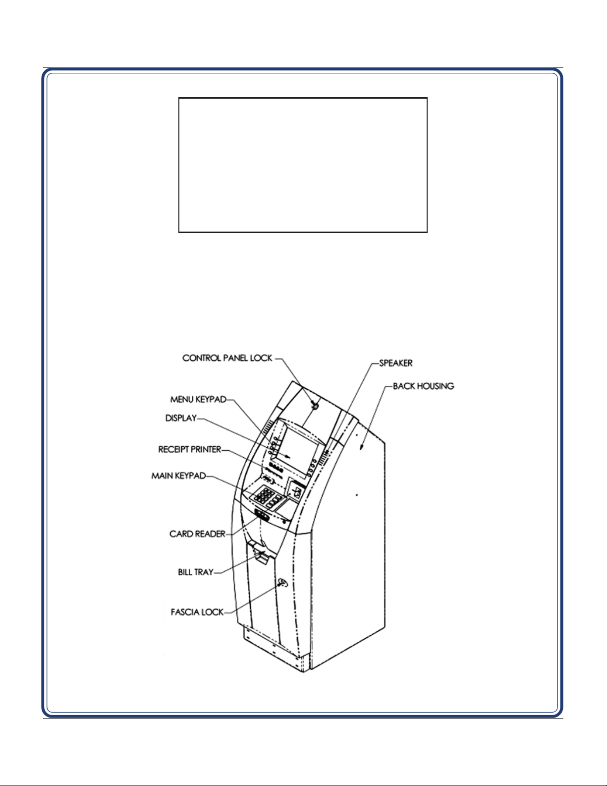
MODEL RL5000 (X2)
AUT OMATED TELLER MACHINE
INSTALLATION GUIDE
TDN 07100-00091-00 Jan 8 2013
CORPORATE HEADQUARTERS
21405 B St.
Long Beach, MS 39560
Phone: (800) 259-6672
Fax: (228) 868-9445
© 2013 T riton. All Rights Reserved. TRIT ON logo is
a registered trademark of Triton Systems of Delaware
Page 2
MODEL RL5000 (X2) INSTALLATION GUIDE
INTRODUCTION
The T riton RL5000 (X2) is a lobby terminal designed for indoor use only . The following sections provide
the requirements for installing the RL5000 for your particular site location. T o assist you in preparing your
site, a check list is provided of various steps that should be carried out
prior to the arrival of the ATM.
WHA T ’SIN THIS INSTALLATION GUIDE
This Installation Guide provides information for the physical installation of the RL5000 ATM. It contains
requirements for site preparation, electrical specifications, and cabinet accessibility that comply with all
relevant codes, laws and regulations. The Installation Guide is divided into the following sections:
SITE COMPLIANCE. States the customers responsibilities for ensuring all relevant regulations are adhered
to for installing ATMs.
ATM ENVIRONMENTAL PRECAUTIONS CHECKLIST. Describes the general environmental precautions
considered when installing the ATM. To help ensure proper operation of the ATM, ensure the
environmental criteria listed in this checklist are met.
DIMENSIONS. Describes physical dimensions for the cabinet(s), control panel components, and signage.
¾ Physical dimensions.
¾ Service area dimensions.
¾ Customer access dimensions
INSTALLATION. Describes anchoring the cabinet using standard (steel) or the optional chemical anchors.
DISPENSER INSTALLATION. Describes the installation of the SDD dispenser.
* NOTICE *
The Model RL5000 (X2) A TM supports most models of TDM mechanisms, but starting Apr, 08’,
Triton will only ship the TDM-250 in production units. The SDD and NMD-50 dispensers will
continue to be offered. The SDD may be shipped in a seperate container.
POWER AND COMMUNICATION. Shows cable access area, power requirements, and powering-up the
unit.
TCP/IP OR VSA T CONNECTIVITY. Shows unit cable connectivity for communication protocols TCP/IP
and VSAT.
APPENDIX A. Software License Agreement / Compliance/Emissions statements
APPENDIX B. ATM Installation for Accessibility guidelines.
2
Page 3

MODEL RL5000 (X2) INSTALLATION GUIDE
CONTENTS
SITE COMPLIANCE ......................................................................................................... 4
E
NVIRONMENTA L PRECAUTIONS ...................................................................................... 5
TEMPERATURE / POWER / RF INTERFERENCE REQUIREMENTS ........................................................................ 6
DIMENSIONS GENERATION 2 .......................................................................................... 7
DIMENSIONS GENERATION 3.......................................................................................13
C
ABINET INSTALLATION ................................................................................................. 19
TOOLS REQUIRED .................................................................................................................................... 20
U
NPACKING THE UNIT .............................................................................................................................. 20
M
ARK / DRILL MOUNTING HOLES ............................................................................................................ 22
I
NSTALLING STANDARD ANCHORS / BOLT ATM .......................................................................................... 23
I
NSTALL CHEMICAL ANCHORS / BOLT ATM ............................................................................................... 2 4
SDD DISPENSER INSTALLATION .................................................................................... 27
POWER AND COMMUNICATION ...................................................................................... 31
ROUTE / CONNECT CABLES ...................................................................................................................... 32
TCP/IP C
VSA T C
ONNECTIVITY ............................................................................................................................. 34
ONNECTIVITY ............................................................................................................................... 35
APPENDIX A - SOFTWARE LICENSE AGREEMENT / COMPLIANCE/EMISSIONS STATEMENTS
APPENDIX B - A TM INSTALLATION FOR ACCESSIBILITY
DOCUMENT UPDATES
DEC 11 2009 ADDED DIMENSIONS FOR GENERATION 3 CABINET AND VAULT.
JAN 8 2013 ADDED DIMENSIONS FOR DECAL PLACEMENT
3
Page 4
MODEL RL5000 (X2) INSTALLATION GUIDE
SITE COMPLIANCE
This document contains the information necessary for the preparation and installation of an RL5000 Triton
ATM. It’s important that the site complies with the requirements specified in this document. In addition,
electrical wiring and mechanical systems must also comply with all relevant laws and regulations.
The site must be prepared by the customer or his agent who is fully conversant with the requirements of
installing ATM equipment. The responsibility for ensuring that the site is prepared in compliance with this
document remains with the customer.
For information and guidance only, a list is provided in general terms of those matters for which the
customer is responsible. The list is not intended to be comprehensive and in no way modifies, alters, or
limits the responsibility of the customer for all aspects of adequate site preparation.
1. Location of the equipment and site preparation.
2 . Site wiring (power , communication).
3 . Location of other equipment that may cause electrical, electromagnetic or heat induced interfer-
ence.
4 . Make building alterations to meet wiring and other site requirements.
5 . Install all communication cables, wall jacks, and associated hardware.
6. Provide and install necessary power distribution boxes, conduits, and grounds.
7 . Ensure all applicable codes, regulations, and laws (electrical, building, safety) are adhered to.
8 . Ensure the environmental requirements of this unit are met.
9 . Install the unit at a height which meets the ADA/DDA/CSA accessibility regulations for the state/
country installed.
TSILKCEHCNOITARAPERPETIS
nalproolfangiseddnaetistceleS
temsnoitidnoclatnemnorivneerusnE
seludehcsrodnevdnarotcartnochsilbatsE
stnemeriuqerenilnoitacinummockcehC
sdeenyrosseccanoitallatsninalP
yrassecenekamdnanalproolfkcehC
snoitaretla
stnemeriuqerlacirtcelellatsnI
sdeennoitacinummocrofetiseraperP
)lanoitpo(gniniartrotareponalP
tsetdnasenilnoitacinummocllatsnI
elbaliavaeraseirosseccanoitallatsnierusnE
4
Page 5

MODEL RL5000 (X2) INSTALLATION GUIDE
ENVIRONMENTAL PRECAUTION CHECKLIST
5
Page 6
MODEL RL5000 (X2) INSTALLATION GUIDE
When installing an A TM, some general environmental and power precautions need to be considered. Evaluate the location where the A TM will be
installed. T o help ensur e proper operation of the A TM, ensure the environmental criteria listed in this checklist are met.
TEMPERATURE / HUMIDITY
1. The ATM will operate over a range of tem-
peratures and humidity . Generally , these parameters must fall within the following
ranges:
Temperature
• 10°C to 40°C
• 50°F to 104°F
Relative Humidity
• 20% to 80%
• (Non-Condensing)
AC POWER REQUIREMENTS
2. Ensure the following AC power requir ements
are met:
Current (Max)
• 2.2A @ 115 VRMS at 60 Hz
• 1.1A @ 230 VRMS at 50 Hz
Voltage
• 90 - 136VRMS @ 50/60 Hz
• 198 - 257VRMS @ 50/60 Hz
Power Consumption (Idle)
• 0.6A @ 115 VAC at 60 Hz
* IMPORT ANT *
AC power for the terminal should come from a
dedicated source with an isolated ground.
Dedicated source. The ATM AC power feed will be
a dedicated line, to which no other electrical devices
are connected. The ATM power line will be wired for
a single “duplex”-style outlet and connected directly
to the AC service panel.
Isolated Ground. An equipment grounding conductor that is insulated from the conduit or raceway and
all other grounding points throughout its entire
length. The only points of electrical connection will
be at the duplex outlet and service panel ends of the
line.
DEDICA TED TELEPHONE
3. Ensure the following telephone-line requirements are met:
Dedicated line. The telephone line servicing the ATM
will not be a “party” line or any other shared type
connection.
Proximity to Interference Sources. T h etelephone
line must not be in close proximity to “noisy” devices that could induce interference into the ATM
communications channel. See the next section for
additional information on “interference sources.”
• 0.3A @ 230 VAC at 50 Hz
Power Consumption (Max Load)
• 250 Watts @ 120V AC
• 250 Watts @ 240V AC
Surge ~50A @ 230V
RF INTERFERENCE
4. Ensure there are no devices near the terminal
that may cause RF interference, such as:
TVs
Coolers
Security devices
Neon signs
Devices with compressors
6
Page 7
MODEL RL5000 (X2) INSTALLATION GUIDE
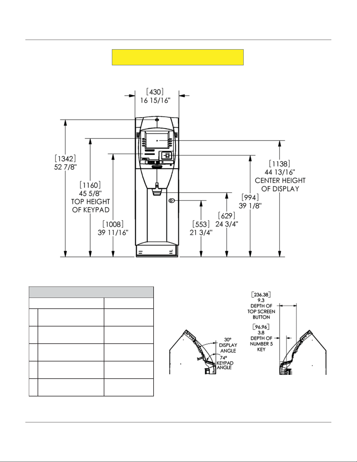
Dimensions listed comply with US Federal ADA
Guidelines. For USA installations, check for
additional guidance. For non-USA installations,
check regulations relating to the country of
install.
Note:
Dimensions shown in inches and [millimeters]
DIMENSIONS
7
Page 8
MODEL RL5000 (X2) INSTALLATION GUIDE
Generation 2 Cabinet
and V ault
CUSOMER ACCESS DIMENSIONS
1yeKnoitcnuFpoT
2retneCyalpsiD
3redaeRdraC
4retnirPtpieceR
5yarTlliB
snoisnemiDsseccAremotsuC
erutaeFthgieH
"8/5-54
]mm0611[
"61/31-44
]mm8311[
"8/1-93
]mm499[
"61/11-93
)mm8001[
"4/3-42
]mm926[
8
Page 9
MODEL RL5000 (X2) INSTALLATION GUIDE
SERVICE AREA DIMENSIONS
2" [51] clearance around
cabinet sides and rear
snoisnemiD
noisnemiD)tluaV(1leveLsruoHssenisuB
A]335["12~]335["12~
B]065["61/1-82]696["8/3-72
C]065["61/1-22]345["8/3-12
D]863["2/1-41]922["9
E]267["03]117["82
9
]sretemillim[dna)"(sehcnininwohS
Page 10
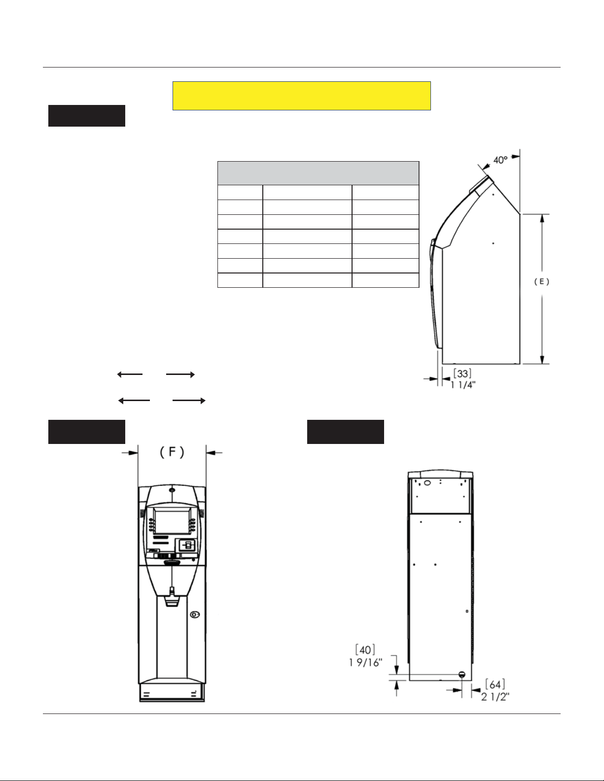
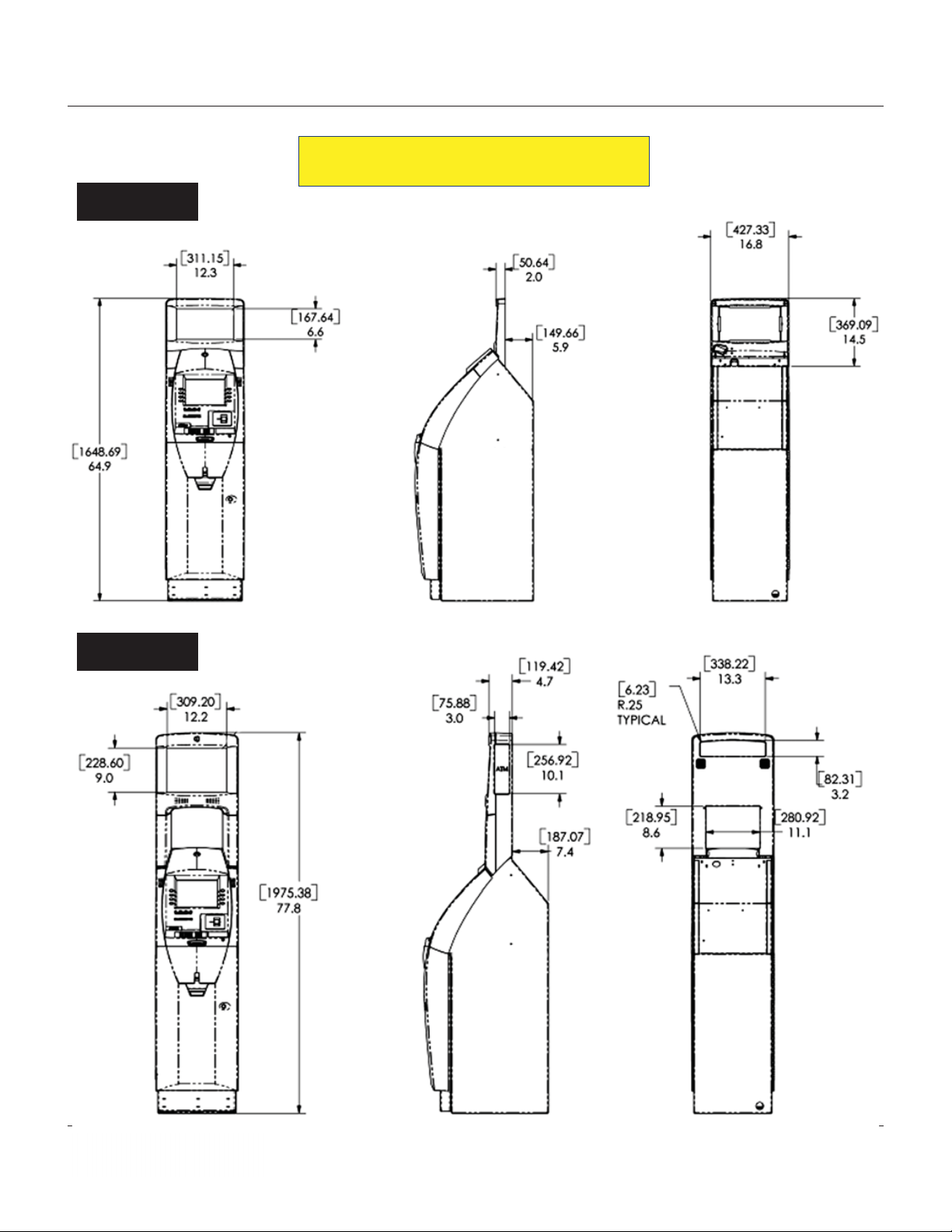
Side Views
MODEL RL5000 (X2) INSTALLATION GUIDE
PHYSICAL DIMENSIONS
snoisnemiD
noisnemiD)tluaV(1leveLsruoHssenisuB
A]8731["4/1-45]8731["4/1-45
B]375["61/9-22]265["8/1-22
C]266["61/1-62]156["8/5-52
D]542["8/5-9]432["61/3-9
E]0901["8/7-24]0901["8/7-24
F]034["61/51-61]034["61/51-61
Front View Rear View
]sretemillim[dna)"(sehcnininwohS
10
Page 11
MODEL RL5000 (X2) INSTALLATION GUIDE
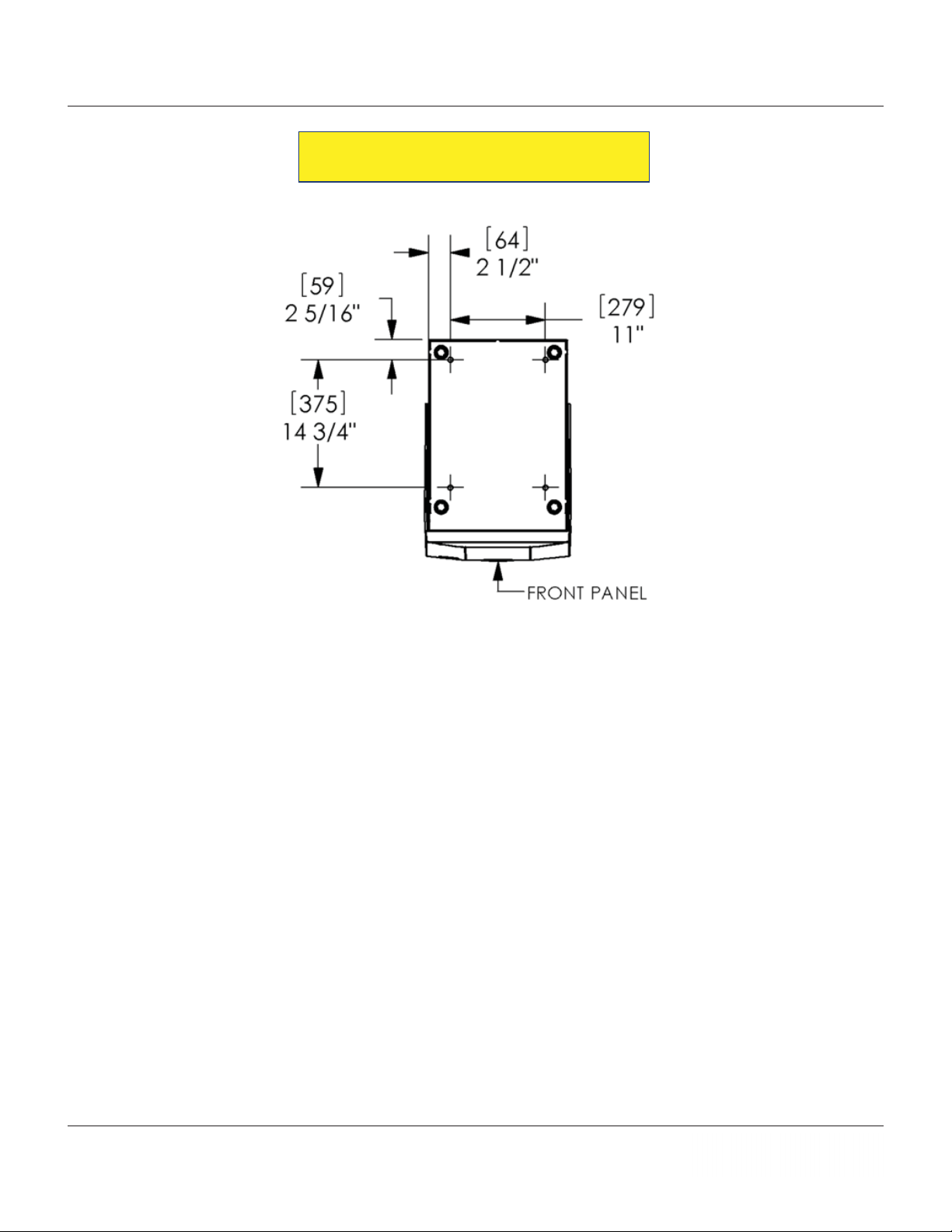
CABINET “FOOTPRINT”
11
Page 12
Midtopper
MODEL RL5000 (X2) INSTALLATION GUIDE
SIGNAGE
Hightopper
12
Page 13

MODEL RL5000 (X2) INSTALLATION GUIDE
Generation 3Cabinet
and V ault
CUSOMER ACCESS DIMENSIONS
13
Page 14

MODEL RL5000 (X2) INSTALLATION GUIDE
SERVICE AREA DIMENSIONS
14
Page 15

MODEL RL5000 (X2) INSTALLATION GUIDE
PHYSICAL DIMENSIONS
15
Page 16

Hightopper
MODEL RL5000 (X2) INSTALLATION GUIDE
16
Page 17

Midtopper
MODEL RL5000 (X2) INSTALLATION GUIDE
17
Page 18

MODEL RL5000 (X2) INSTALLATION GUIDE
DECAL AREA Business Hours Cabinet Built 10/22/04 - 1/16/12
Level One Vault built before 8/2/09
18
Page 19

MODEL RL5000 (X2) INSTALLATION GUIDE
19
Page 20

MODEL RL5000 (X2) INSTALLATION GUIDE
DECAL AREA Level One V ault beginning in 8/3/09
20
Page 21

MODEL RL5000 (X2) INSTALLATION GUIDE
21
Page 22

MODEL RL5000 (X2) INSTALLATION GUIDE
Intentionally Blank
22
Page 23

MODEL RL5000 (X2) INSTALLATION GUIDE
CABINET INSTALLATION
23
Page 24

MODEL RL5000 (X2) INSTALLATION GUIDE
CABINET INSTALLATION
The following procedure applies to installing the cabinet assembly using either standard (P/N 06200-00066)
or chemical (06200-00060) anchor kits, supplied seperately .
* IMPORTANT *
Model RL5000 ATM is designed for indoor use only!
deriuqeRslooT
,sdnuoptoof06tsaeltaotelbatsujda,hcnerweuqroT
hcnerwtehctarro,hcnerwtnecsercelbatsujda
stniopllirdgnikramrof)tnelaviuqero(hcnupretneC
remmaHtekcos)mm91("4/3revirdwercstalfegraL
levelelbbuBhcnerwxob/tekcos"61/7selggogytefaS
,)mm21("2/1,)mm6("4/1
noitcetorpgniraeH
gnol"6tsael
-edibrac)mm51("61/9dna
ta-stibllirdyrnosamdeppit
cirtceleytud-yvaeh"4/3
)remmah/yrator(llird
tlebtroppuskcaBrenaelcmuucavelbatroPhsurberiW
tiKrohcnAdradnatS
srehsawtalf"2/1
epyt-eveels"4/1-4x"2/1
stlobrohcna
stun"2/1
tiKrohcnAlacimehC
dnastunxeH
srehsaw
seluspacrohcnalacimehC
sdor
tniop-lesihcdedaerhT
UNPACK ATM
1. Carefully inspect the shipping container for any damage and report any damage immediately to the
shipping company . Refer to the warranty information in the User manual for information about reporting
shipping damage.
2. Remove the ATM cabinet from the shipping carton.
3. Remove the silver key from the plastic bag attached to the ATM wrapping.
24
Page 25

MODEL RL5000 (X2) INSTALLATION GUIDE
4. Use the silver key to unlock both the control panel and the fascia door (which conceals the locking
mechanism) on the front of the cabinet. Open the fascia door.
5. Lift the handle under the bill chute to open the front enclosure door. If the door is locked, see the
sidebar at bottom of page for help in unlocking the electronic lock.
Note: To change the combinations, see Appendix C in the User Manual (included on CD).
6. Remove the packing material from inside the vault enclosure. Inspect the dispenser and report any
damage to Triton.
7. The accessory box is shipped inside the cabinet enclosure. Open and inspect the contents. Check the
contents against the enclosed packing list and report any missing parts to Triton.
**WARNING**
DO NOT APPL Y POWER TO THIS TERMINAL
UNTIL THE INSTALLA TION IS COMPLETE!!
UNLOCKING COMBINA TION LOCK
LAGARD LOCK
The combination of the lock is preset to 1-2-3-4-5-6. To unlock,
enter the preset combination and check for proper operation. After
each keypress, the lock will
entered, the lock will beep twice, and the open period begins. When
a valid combination has been entered, the operator will have approximately 3 seconds to open the lock. To open the lock, turn the
outer ring of the dial clockwise. After the lock is opened, the vault
door may be opened.
K
ABA MAS
1. Turn the dial left (CCW) until the letters “EC” (Enter Combina-
tion) appear on the LCD.
2. Enter the factory combination of 50-25-50 by sequentially press-
ing those six (6) buttons. The LCD will display these numbers
as they are entered.
3. When the combination has been correctly entered, the LCD will
read “OPr”, meaning “OPen right”. Turn the dial right (CW)
until it stops. The locks bolt is now retracted and the lock is
open.
‘beep’. After the final digit has been
4. After the lock is opened, the cabinet door may be opened.
25
Page 26

MODEL RL5000 (X2) INSTALLATION GUIDE
MARK/DRILL MOUNTING HOLES
Mark the location of the cabinet mounting holes on the concrete
floor . This is accomplished as described below:
1. Move the ATM to the location where it will be installed.
Open the cabinet vault door at least 90° to improve access.
Locate the four (4) anchor-bolt holes in the bottom of the
cabinet (each corner). Use a felt-tip pen or other marker to
carefully mark the center of each of these four holes on the
floor; these marks will serve as guides for the anchor bolt
holes that will be drilled in the next step. Move the A TM aside
to provide clear access to the mounting hole marks. Center
punch each mark to help align the drill bit.
2. Use a 1/4" [6 mm] diameter carbide-tipped masonry bit to drill
four pilot holes at the drilling points marked in the previous
step. Drill the pilot holes approximately 1/2" [12 mm] deep into
the floor . These holes will help guide the masonry bit that will
be used to drill the anchor-bolt holes in the next step.
SELECTING THE
INST ALLA TION LOCATION
Choosing the right location for your
ATM is very important. Security
concerns suggest a location that is
away from any door or external access point. Ideally, the terminal
should be mounted as close to a
back wall as possible. For marketing reasons, however, it may be desirable to locate the terminal near
the front where your customers can
easily locate it. Wherever you decide to locate the terminal, be sure
to follow the recommended procedures for both mounting the terminal and for removing cash when
the unit will be unattended.
3. Standard anchors: Use a 1/2" [13mm] diameter carbide-tipped
masonry bit to drill four holes at least 2-3/4" [70mm] deep
into the floor. Be sure to take into account the depth of any
floor covering, such as tile or vinyl when gauging the depth
of the anchor holes. Make sure the holes are drilled at least
2- 3/4" into the
3a . Chemical anchors: Use a 9/16" [15mm] diameter carbide-
tipped masonry bit to drill four holes at least 4-1/2" [1 15mm]
deep into the floor. Be sure to take into account the depth of
any floor covering, such as tile or vinyl when gauging the
depth of the anchor holes. Make sure the holes are drilled at
least 4- 1/2-inches [115mm] into the
concrete floor.
concrete floor.
TOOL USE/SAFETY
Observe ALL safety precautions for
operating hand and power tools!
Wear eye and ear protection while
operating the electric drill!
CONCRETE STRENGTH
The floor at the installation location should consist of commercial-grade concrete measuring at
least
2000 psi in compression
strength.The full effectiveness of
the mounting anchors depends
upon meeting this specification!
Check with the contractor/builder
or owner of the installation to
verify that this requirement can
be satisfied.
26
Page 27

MODEL RL5000 (X2) INSTALLATION GUIDE
4. Use a portable vacuum cleaner to remove any dust or debris that may have fallen into the holes during
the drilling process.
Drill anchor holes Blow out dust/debris.
INSTALL STANDARD ANCHORS
BOLT ATM TO FLOOR
1. Ensure the leveling feet are flush with the bottom of the cabinet. If necessary, use a screwdriver to
adjust the leveling bolts inside the cabinet (near the four corners) so that the leveling feet are flush with
the bottom of the cabinet.
2 Move the ATM into position for mounting by aligning the base over the four holes drilled in the
previous procedure.
3 Place an anchor bolt through the cabinet base and into one of the mounting holes. Use a ball peen
hammer to tap the bolt completely into the hole.
IMPORTANT : If the anchor bolt “falls” into the hole without needing to be t apped in, the hole is too
large! The mounting-hole pattern will have to be moved and redrilled using smaller holes as
necessary to achieve a snug fit.
Place anchor bolts in mounting holes. Tap anchor bolts into mounting holes.
27
Page 28

MODEL RL5000 (X2) INSTALLATION GUIDE
4. Place a flat washer on the anchor bolt followed by a 1/2” (13mm) nut.
5. Repeat Steps 2 and 3 for the remaining anchor bolts.
6. Ensure the cabinet is as level as possible given the floor conditions. Use a bubble level to verify this.
If a bubble-level is not available, the cabinet can be “rocked” gently from front-to-back and side-toside to check the need for leveling.
7. Use a torque wrench and 3/4” [19mm] socket to tighten each nut to a torque setting of
(required to establish the maximum pull-out strength of the anchors). If a torque wrench is not
available, use a ratchet wrench and 3/4” [19mm] socket to tighten the nuts
tight.
8. Once the nuts are tightened as specified in Step 7, install a second nut on each bolt and tighten down
firmly.
three full turns beyond hand
60 foot-pounds
INSTALL CHEMICAL ANCHORS
BOLT ATM TO FLOOR
1. Move the ATM into position for mounting by aligning the base over the four holes drilled in the
previous procedure.
2. Begin by inserting a Chem Stud capsule into one of the mounting holes. Either end of the capsule may
be inserted first.
3. Place a washer and a nut (in that order) onto a chisel point rod. Thread the nut onto the rod, leaving 3
to 4 threads exposed.
4. Thread the rod coupler onto the threaded rod until it is tight against the nut. The threaded rod used
should be free of dirt, grease, oil or other foreign material.
5. Select the drive unit, insert it into a rotary hammer drill and engage the coupling to be used.
Prepare chisel point anchor rod.
Insert Chem Stud capsule in mounting hole.
28
Add washer and nut.
Page 29

MODEL RL5000 (X2) INSTALLATION GUIDE
6. Insert the chisel point of the rod into the hole to break the glass capsule. Spin it into the capsule at a
speed of 250 to 500 RPM, until it is fully embedded. IMPORTANT! Turn the rotary hammer drill
OFF IMMEDIA TEL Y when the rod is fully embedded!
7. Pull the driver out of the coupling while holding the rod. Hold the hex nut with a wrench to unthread the
coupler.
8. Repeat steps 1-7 for each of the remaining mounting holes.
9. Allow the adhesive to cure for the specified time (see chart and important
not, which follow) prior to applying any load to the anchors. During the
winter, the hole temperature may be different than the room temperature!
The hole temperature should be measured to determine the curing time
required. DO NOT disturb or load the anchors until they are fully
cured!
Allow seated anchor
*erutarepmeTlairetaMesaB emiTgnitteS
revodnaCº02/Fº86setunim02
Cº02/Fº86otCº01/Fº05setunim03
Cº01/Fº05otCº0/Fº23ruoh1
Cº0/Fº23otCº5-/Fº32sruoh5
Cº5-/Fº32otCº01-/Fº41sruoh01
to cure.
10. Ensure the ATM is as level as possible given the floor conditions. Use a bubble level to verify this. If
a bubble-level is not available, the cabinet can be “rocked” gently from front-to-back and side-to-side
to check the need for leveling.
11. Use an adjustable wrench or a ratchet wrench with 3/4" [19mm] socket to tighten the nuts down. No
minimum torque setting for the nuts is required. Simply ensure the nuts are tightened down firmly
enough to secure the plinth to the anchors. Tightening the nuts just beyond hand tight should prove
adequate.
12. Once the ATM is square (level), install a second nut on each bolt and tighten down firmly.
29
Page 30

MODEL RL5000 (X2) INSTALLATION GUIDE
THIS PAGE INTENTIONALLY LEFT BLANK
30
Page 31

MODEL RL5000 (X2) INSTALLATION GUIDE
SDD DISPENSING
MECHANISM
INSTALLATION
31
Page 32

MODEL RL5000 (X2) INSTALLATION GUIDE
INSTALLING THE SDD DISPENSING
MECHANISM
The SDD dispensing mechanism is shipped inside the
cabinet of the RL5000 security cabinet in its own
container. Remove it from inside the cabinet before the
ATM is bolted to the floor.
1. Refer to Figure 1. Unlock and open the control
panel. V erify that the power switch is in the OFF (0)
position. Close the control panel.
Figure 1. Power switch on left side of
power module.
2 . Remove the packing material from the ends of the
dispenser data and power cables that are hanging
inside the cabinet.
Figure 2. SDD dispenser tray pulled
out to extended position.
6 . Refer to Figure 3. Connect cable 9600-0043 to the
DB25 connector (PL6) on the rear of the dispenser
mechanism. Secure the DB25 cable to the
dispenser with two screws attached to the
connector. Insert the Molex power plug attached
to cable 9600-0013 into the connector marked PL2.
This plug is keyed so that it can only be inserted
in one direction.
3 . Unpack and remove the ATM mechanism from its
shipping container .
4. Pull the cassette tray out to its fully extended
position as shown in Figure 2.
5 . Pick up the dispensing mechanism and place it on
the cassette tray. Leave enough room to easily
access the back of the dispensing mechanism so it
can be connected to the cables coming from the
ATM.
Figure 3. Connections for DC power
and communications.
32
Page 33

MODEL RL5000 (X2) INSTALLATION GUIDE
7. Refer to Figure 4. Install the dispensing mechanism
by sliding the end with the circuit board into the
tray in the cabinet. The mechanism should slide
under two tabs in the rear and the front edge slots
should align with the two bolts provided with wing
nuts. Once the mechanism is fully engaged into
the tray, tighten the wing nuts by hand.
Figure 4. Installing the dispensing
mechanism.
8 . The A TM is quite tolerant of power line variations.
However, AC power for the terminal should come
from a dedicated source with an isolated ground.
Route the AC power cord and the phone cord
out through the hole in the back of the cabinet
and install the split ring grommet into the hole.
Attach the ground cable to the dispenser.
Ground
Connection
9 . Connect the AC input plug to the wall outlet (See
Note below and section on connecting power and
communications cables before proceeding with
Step 10).
**IMPORT ANT**
• Electrical rating of the A TM: 200-250 V AC, 50-60 Hz, 2.60 amps.
• The ATM is designed to work on an IT (Isolated Terra)-type power system having a phase-tophase voltage not exceeding 250 volts.
• The AC socket-outlet shall be installed near the equipment and shall be easily accessible.
POWER SUPPL Y CORD - SPECIFICA TIONS
For European applications, the power supply cord must conform to the following
specifications:
1. ) T wo-conductor with Protective Earth (PE) ground.
2. ) IEC 320 molded connector on one end and molded plug on the other
end.
3. ) Certified for country of installation.
4.) Rated minimum H05VV -F with minimum 0.75 mm
countries require 1.0 mm
2
) conductors.
2
(except where specific
5.) Maximum length: 3 meters.
33
Page 34

MODEL RL5000 (X2) INSTALLATION GUIDE
DO NOT PROCEDE WITH STEP 10
UNTIL THE INST ALLA TION
b. Select Diagnostics from the Management
Functions screen, then Dispenser.
IS COMPLETE
10. Install currency in the cassette and insert into
the dispensing mechanism. Refer to Section 4,
Cash Replenishment, in the RL5000 User manual
for detailed information about handling cassettes.
**CAUTION**
Make sure the cassette is primed
and the window below the lock
displays green before installing
the cassette. Attempting to install
an unprimed cassette into a
dispensing mechanism may
damage the cassette and void its
warranty .
11 . Open the control panel and apply AC power to the
ATM by pushing the AC power switch to the ON
(1) position.
c. Select the Test Dispense option. Select cassette
“A”. A prompt appears asking how many notes
to dispense. (Figure 5) The Test Dispense
operation will start.
Figure 5. Enter # of notes.
d. The Test Dispense command instructs the
dispenser to dispense, minimum, one note from
the the note Cassette into the reject tray of the
cassette. This test exercises the dispenser without
sending notes to the exit.
e. After completion of the T est Dispense operation,
the following prompt is displayed - “T est Dispense
Completed Successfully - Dispense Count, A: (#
of notes)”.
(Figure 6)
12 . Complete the ATM setup, if necessary , according
to the instructions in the RL5000 Configuration
manual or applicable Service manual.
13. Follow the remaining steps to perform a Test
Dispense:
a. Access the Management Functions
main menu screen. Refer to RL5000
User Manual for instructions on
accessing the Management
Functions main menu.
Figure 6. Test dispense prompt.
34
Page 35

MODEL RL5000 (X2) INSTALLATION GUIDE
ROUTE POWER AND COMMUNICATION
35
Page 36

MODEL RL5000 (X2) INSTALLATION GUIDE
Route AC Power and
Communication Cable
NOTE: Before you start, unlock and open the control panel. Verify that the power switch on the unit’s
power supply is in the OFF (0) position. Close the control panel.
1. Route the AC power cord and the phone (or Cat-5) cable through either the main or alternate cable
access hole (as applicable).
2. Connect the AC power cord and communication cable to their respective facility outlets.
3. Secure/plug the unused access hole with the grommet or plug provided.
This unit may be equipped with more than one power cord. Disconnect All power cords prior to
Servicing! For continued fault protection, follow the correct voltage and current ratings when replacing any fuses.
36
Page 37

MODEL RL5000 (X2) INSTALLATION GUIDE
Power Outlet Accessibility
Whether you are installing a new AC socket outlet or plan to use an existing
outlet to supply power to the ATM, make sure the following requirements are
met:
1. The outlet is located near the equipment.
2. AC power for the terminal should come from a dedicated source with an
isolated ground. The ATM is designed to work on an IT (Isolated-Terra)
type power system having a phase-to-phase voltage not exceeding 240
volts.
3. The outlet is easily accessible and will not be blocked once the equip-
ment is installed.
POWER SUPPL Y CORD -
SPECIFICA TIONS
For European applications, the power
supply cord must conform to the following specifications:
1. Two-conductor with Physical
Earth (PE) ground.
2. IEC 320 molded connector on
one end and molded plug on the
other end.
3. Certified for country of
installation.
4 . Rated minimum H05VV -F with
minimum 0.75 mm2 (except where
specific countries require 1.0
mm2) conductors.
5. Maximum length: 3 meters.
37
Page 38

MODEL RL5000 (X2) INSTALLATION GUIDE
TCP/IP (ETHERNET)
The Ethernet option makes your RL5000 ATM LAN (Local Area Network) or WAN (Wide Area Network)
capable. The ATM functions that are normally performed via the dial-up telephone system, such as
customer transactions and remote monitoring, can now be performed using existing in-house communications network. ATM transaction processing and hardware monitoring functions are performed across a
shared network medium. Ethernet is popular because it strikes a good balance between speed, cost and
ease of installation. These benefits, combined with wide acceptance in the computer marketplace and the
ability to support virtually all popular network protocols, make the Ethernet option an ideal networking
solution for your RL5000 A TM.
TCP/IP CABLE (CA T-5) CONNECTIVITY
1 . If the unit is ON, enter MANAGEMENT FUNCTIONS > SYSTEM PARAMETERS > SHUT DOWN THE TERMINAL.
When prompted on the screen, open the control panel hood and turn the power switch on the power
supply to the OFF (0) position.
2 . Refer to the section on
“Power and Communication”. Route the 10Base-T (CAT-5) cable through the
cabinet base cable access hole. Secure cable inside vault area and continue up to the control panel
access holes.
3. Connect the RJ-45 end of CAT-5 cable to the TCP/IP connector located on the X2 M
AIN BOARD
assembly as shown in figure below.
4. Secure cable into existing cable harness runs. Refer to the Configuration manual for programming
Ethernet options.
RJ-45 (CA T-5)
TCP/IP P
ORT
USB PORTS
38
Page 39

MODEL RL5000 (X2) INSTALLATION GUIDE
VSA T (SATELLITE)
VSA T stands for “V ery Small Aperture T erminal” and refers to receive/transmit terminals installed at dispersed
sites connecting to a central hub via satellite using small diameter antenna dishes (0.6 to 3.8 meter).
VSAT technology represents a cost effective solution for users seeking an independent communications
network connecting a large number of geographically dispersed sites. VSAT networks offer value-added
satellite-based services capable of supporting the Internet, data, LAN, voice/fax communications, and can
provide powerful, dependable private and public network communications solutions.
INSTALLING THE VSA T CABLES (OPTIONAL KIT)
1 . If the unit is ON, enter Management Functions>System Parameters>Shut Down the T erminal. When
prompted, open the control panel hood and turn the power switch on the power supply to the OFF (0)
position.
2. Refer to the section on
base cable access hole. Secure cable inside vault area and continue up to the control panel access
holes.
3 . Connect the RJ-45 connector end of the Comms cable to the A
assembly.
4 . Connect other end of Comm cable (RJ-45 connector) to the Sub-D adapter. Refer to the Configuration
manual for programming VSAT options.
“Power and Communication”. Route the Comms cable through the cabinet
UXILLARY PORT on the Docking board
Sub-D adapter.
39
Page 40

MODEL RL5000 (X2) INSTALLATION GUIDE
THIS PAGE INTENTIONALLY LEFT BLANK
40
Page 41

APPENDIX A
SOFTWARE LICENSE AGREEMENT
COMPLIANCE / EMISSION STATEMENTS
Page 42

APPENDIX A - SOFTWARE LICENSE AGREEMENT / COMPLIANCE/EMISSION STATEMENTS
AUTOMATED TELLER MACHINE (“A TM”) SOFTWARE
END-USER AGREEMENT
IMPORTANT: PLEASE READ CAREFULLY:
BY INST ALLING OR OTHER WISE USING THE ATM, YOU (AS THE OWNER OR LESSEE OF THE A TM).
AGREE TO BE BOUND BY THE FOLLOWING TERMS AND CONDITIONS, INCLUDING, WITHOUT
LIMIT A TION, THE W ARRANTY DISCLAIMERS, LIMIT A TIONS OF LIABILITY AND TERMINA TION
PROVISION WHICH APPL Y T O YOUR USE OF THE A TM SOFTW ARE CONTAINED IN THIS A TM AND
IS HEREBY LICENSED BY TRITON SYSTEMS OF DELA W ARE, INC. (“T riton”) TO YOU PURSUANT TO
THIS AGREEMENT.
IF YOU DO NOT AGREE TO OR ARE NOT WILLING TO BE BOUND BY THE TERMS AND CONDITIONS
OF THIS AGREEMENT , DO NOT INST ALL OR OTHERWISE USE THIS A TM AND PROMPTL Y CONT ACT YOUR VENDOR. INST ALLING OR OTHERWISE USING THE ATM INDICA TES THAT YOU ACCEPT THESE TERMS.
This A TM is manufactured by , and utilizes proprietary software owned by T riton Systems of Delaware, Inc.
and/or its suppliers. All right, title and interest in and to all component software installed or embedded in
the ATM (“ATM Software”) including all associated intellectual property rights, are and will remain the
property of Triton and/or its suppliers.
LICENSE: T riton grants you a limited, nonexclusive license to use the ATM Software but only in connection with the operation of this ATM subject to the terms and restrictions set forth in this License Agreement.
Y ou are not permitted to use the ATM Software in any manner not expressly authorized by this License. You
acknowledge and agree that ownership of the ATM Software and all subsequent copies thereof regardless
of the form or media are held by Triton or its suppliers.
The software is licensed for use on this specific Triton ATM product and may not be used on any other
product. Otherwise, the supporting documentation, if any, may be copied only as essential for backup or
archive purposes in support of your use of the ATM. Y ou must reproduce and include all copyright notices
and any other proprietary rights notices appearing on any copies that you make.
ASSIGNMENT : NO REVERSE ENGINEERING: Y ou may transfer the A TM Software to another party but
only in connection with a transfer of all your right, title and interest in and to this ATM and if such party
accepts the terms and conditions of this License Agreement. If you transfer the ATM, you must at the same
time transfer the supporting documentation, if any, to the same party or destroy any such materials not
transferred. Modification, reverse engineering, reverse compiling, or disassembly of the ATM and/or the
ATM Software is expressly prohibited.
A-2
Page 43

APPENDIX A - SOFTWARE LICENSE AGREEMENT / COMPLIANCE/EMISSION STATEMENTS
DISCLAIMER OF WARRANTIES AND LIMIT ATION OF DAMAGES
TO THE EXTENT PERMITTED BY LA W , THIS ATM SOFTW ARE, INCLUDING ALL INCORPORATED
THIRD P AR TY SOFTW ARE, AND DERIV ATIVES IS PROVIDED, “AS IS”. TRITON MAKES NO REPRESENT A TIONS WITH RESPECT TO, AND DOES NOT WARRANT THE PERFORMANCE OR RESUL TS
YOU OR YOUR CUSTOMERS MA Y OBTAIN BY USING THE A TM. TRITON SPECIFICALL Y DISCLAIMS
ANY AND ALL W ARRANTIES, EXPRESS, IMPLIED OR ST ATUTOR Y , INCLUDING WITHOUT LIMITATION, W ARRANTIES OF QUALITY, PERFORMANCE, NONINFRINGEMENT , AND MERCHANT ABILITY OR FITNESS FOR ANY P AR TICULAR PURPOSE.
TRITON MAKES NO REPRESENT A TIONS OR W ARRANTIES AND ASSUMES NO OBLIGATIONS TO
YOU OR YOUR CUSTOMERS WITH RESPECT T O ANY TRANSACTION OR SER VICES ACCESSED
AND/OR UTILIZED IN CONSUMER-INITIA TED TRANSACTIONS MADE FROM THIS ATM. IN NO
EVENT WILL TRIT ON, ITS AFFILIA TES, DIRECTORS, OFFICERS, EMPLOYEES, AGENTS OR SUPPLIERS BE LIABLE TO YOU UNDER ANY THEORY OF TOR T , CONTRACT, STRICT LIABILITY OR OTHER
LEGAL OR EQUIT ABLE THEOR Y FOR ANY PUNITIVE, CONSEQUENTIAL, INCIDENT AL, SPECIAL OR
SIMILAR DAMAGES, INCLUDING ANY LOSS PROFITS OR LOST SA VINGS, EVEN IF A TRITON AGENT
OR REPRESENT A TIVE HAS BEEN ADVISED OF THE POSSIBILITY OF SUCH DAMAGES, OR FOR ANY
CLAIM BY ANY THIRD P A RTY.
YOUR SOLE REMEDY AGAINST TRITON FOR DEFECTIVE PERFORMANCE OF THE A TM SOFTW ARE
WILL BE LIMITED EXCLUSIVEL Y TO REP AIR OR REPLACEMENT OF THE A TM AND/OR THE A TM
SOFTW ARE, A T TRIT ON’S SOLE DISCRETION.
Any warranty pertaining to the ATM, its mechanical components exclusive of the ATM software, shall be
governed and controlled by any warranty given to you by Triton in a separate document accompanying
this ATM.
The foregoing limitation of liability and exclusion of certain damages will apply regardless of the success or
effectiveness of other remedies.
GOVERNING LAW: This License Agreement shall be governed by the laws of the S tate of Mississippi and
by the laws of the United States, excluding their conflicts of laws principles.
SEVERABILITY: In the event any provision of this License Agreement is found to be invalid, illegal or
unenforceable, the validity, legality and enforceability of any of the remaining provisions shall not in any
way be affected or impaired.
ENTIRE AGREEMENT : This License Agreement and the accompanying Limited Warranty set forth the
entire agreement between you and Triton, supersedes all prior agreements, whether written or oral, with
respect to the ATM Software, and may be amended only in writing signed by both parties.
A-3
Page 44

APPENDIX A - SOFTWARE LICENSE AGREEMENT / COMPLIANCE/EMISSION STATEMENTS
COMPLIANCE / EMISSION STATEMENTS
DISCLAIMER
The manufacturer of the Automated Teller Machine (ATM) product(s) described herein makes no
representations or warranties, either expressed or implied, by or with respect to anything in this manual, and
shall not be liable for any implied warranties of fitness for a particular purpose or for any indirect, special, or
consequential damages. Information in this document is subject to change without notice and does not
represent a commitment on the part of the manufacturer.
EMISSIONS (EMI)
** CAUTION **
(US Requirements)
This device complies with Part 15 of the FCC rules.
Changes or modifications not expressly approved
by Triton Systems could void the regulatory
compliance approval and the warranty. Use of this
product in a manner other than those described in
this manual may result in personal injury!
Operation is subject to the following two (2)
conditions:
1) This device may not cause harmful interference.
2) This device must accept any interference received,
including interference that may cause undesired
operation.
NOTE:
This equipment has been tested and found to comply with the limits for a Class A digital device pursuant to
Part 15 of FCC rules. These limits are designed to provide reasonable protection against harmful interference
when the equipment is operated in a commercial environment. This equipment generates, uses, and can
radiate radio frequency energy and, if not installed and used in accordance with the instruction manual, may
cause harmful interference to radio communications. Operation of this equipment in a residential area is
likely to cause harmful interference in which case the user will be required to correct the interference at his
own expense. Changes or modifications to this unit not expressly approved by the party responsible for
compliance could void the user’s authority to operate the equipment.
CANADIAN REQUIREMENTS
This digital apparatus does not exceed the Class A limits for radio noise emissions from digital apparatus set
in the Radio Interference Regulations of the Canadian Department of Communications. This Class A digital
apparatus complies with Canadian ICES-003.
Le present appareil numerique n’emet pas de bruits radioelectriques depassant les limites applicables aux
appareils numeriques de la Class A prescrites dans le Reglement sur le brouillage radioelectrique edicte par
le ministere des Communications du Canada. Cet appareil numerique de la classe A est conforme a la norme
NMB-003 Canada.
UK / AUSTRALIA / SOUTH AFRICA REQUIREMENTS
W arning:
This is a Class A product. In a domestic environment, this product may cause radio interference in which
case the user may be required to take adequate measures.
A-4
Page 45

APPENDIX B
A TM INSTALLA TION FOR ACCESSIBILITY
Page 46

APPENDIX B - A TM INSTALLATION FOR ACCESSIBILITY
A Guide to the New ADA-ABA Accessibility Guidelines
On July 23, 2004, the U.S. Access Board, an independent Federal agency, issued updated accessibility
guidelines for new or altered facilities covered by Americans with Disabilities Act and the Architectural
Barriers Act. These guidelines address a wide range of facilities in the private and public sectors. Presented here is an overview of the new guidelines that also highlights significant changes.The following
guidelines (305 and 308) pertain to floor/ground space and reach ranges.
When will the new guidelines take effect?
The Board’s guidelines are not mandatory on the public, but instead serve as the baseline for enforceable
standards (which are) maintained by other Federal agencies. In this respect, they are similar to a model
building code in that they are not required to be followed except as adopted by an enforcing authority.
Under the ADA, the Department of Justice (and in the case of transit facilities, the Department of Transpor tation) are responsible for enforceable standards based on the Board’s guidelines. These agencies will
update their ADA standards based on the new guidelines. In doing so, they will indicate when the new
standards are to be followed. Several other agencies (the General Services Administration, Department of
Defense, Department of Housing and Urban Development, and the U.S. Postal Service) hold a similar
responsibility for standards used to enforce the ABA.
Existing Facilities
The ADA and ABA guidelines cover new construction and planned alterations and generally do not apply
to existing facilities except where altered. Facilities built or altered according to earlier versions of the ADA
or ABA standards will not necessarily have to meet the updated version except where they are subsequently altered or renovated. The Department of Justice, which regulates requirements for existing facilities under the ADA, intends to address coverage of facilities built or altered according to the original ADA
standards in its rulemaking to update the standards. It will also address facilities retrofitted under ADA
provisions for existing facilities, such as the requirement for barrier removal in places of public accommodation. W ith respect to ABA facilities, the Board has clarified in the guidelines that facilities built to earlier
ABA standards are subject to the new requirements only in relation to planned alterations.
305. Clear Floor or Ground Space
305.1 General. Clear floor or ground space shall comply with
305.
305.2 Floor or Ground Surfaces. Floor or ground surfaces of a
clear floor or ground space shall comply with 302. Changes in level
are not permitted.
EXCEPTION: Slopes not steeper than 1:48 shall be permitted.
305.3 Size. The clear floor or ground space shall be 30 inches
(760 mm) minimum by 48 inches (1220 mm) minimum.
B-2
Figure 305.3 Clear Floor or
Ground Space
Page 47

APPENDIX B - A TM INSTALLATION FOR ACCESSIBILITY
305.4 Knee and T oe Clearance. Unless otherwise specified, clear floor or ground space shall be permit-
ted to include knee and toe clearance complying with 306.
305.5 Position. Unless otherwise specified, clear floor or ground space shall be positioned for either
forward or parallel approach to an element.
Figure 305.5 Position of Clear Floor or Ground Space
305.6 Approach. One full unobstructed side of the clear floor or ground space shall adjoin an accessible
route or adjoin another clear floor or ground space.
305.7 Maneuvering Clearance. Where a clear floor or ground space is located in an alcove or otherwise
confined on all or part of three sides, additional maneuvering clearance shall be provided in accordance with
305.7.1 and 305.7.2.
305.7.1 Forward Approach. Alcoves shall be 36 inches (915 mm) wide minimum where the depth exceeds
24 inches (610 mm).
305.7.2 Parallel Approach. Alcoves shall be 60 inches (1525 mm) wide minimum where the depth exceeds
15 inches (380 mm).
Figure 305.7.1 Maneuvering Clearance in an
Alcove, Forward Approach
Figure 305.7.2 Maneuvering Clearance in an
Alcove, Parallel Approach
B-3
Page 48

APPENDIX B - A TM INSTALLATION FOR ACCESSIBILITY
308. Reach Ranges
308.1 General. Reach ranges shall comply with 308.
308.2 Forward Reach.
308.2.1 Unobstructed. Where a forward reach is unobstructed, the high forward reach shall be 48 inches
(1220 mm) maximum and the low forward reach shall be 15 inches (380 mm) minimum above the finish floor
or ground.
Figure 308.2.1 Unobstructed Forward Reach
308.2.2 Obstructed High Reach. Where a high forward reach is over an obstruction, the clear floor space
shall extend beneath the element for a distance not less than the required reach depth over the obstruction.
The high forward reach shall be 48 inches (1220 mm) maximum where the reach depth is 20 inches (510 mm)
maximum. Where the reach depth exceeds 20 inches (510 mm), the high forward reach shall be 44 inches
(1120 mm) maximum and the reach depth shall be 25 inches (635 mm) maximum.
Figure 308.2.2 Obstructed High Forward Reach
B-4
Page 49

APPENDIX B - A TM INSTALLATION FOR ACCESSIBILITY
308.3 Side Reach.
308.3.1 Unobstructed. Where a clear floor or ground space allows a parallel approach to an element and
the side reach is unobstructed, the high side reach shall be 48 inches (1220 mm) maximum and the low side
reach shall be 15 inches (380 mm) minimum above the finish floor or ground.
EXCEPTIONS:
1. An obstruction shall be permitted between the clear
floor or ground space and the element where the depth
of the obstruction is 10 inches (255 mm) maximum.
2. Operable parts of fuel dispensers shall be permitted to be 54 inches (1370 mm) maximum measured from
the surface of the vehicular way where fuel dispensers are installed on existing curbs.
Figure 308.3.1 Unobstructed Side Reach
308.3.2 Obstructed High Reach. Where a clear floor or ground space allows aparallel approach to an
element and the high side reach is over an obstruction, the height of the obstruction shall be 34 inches (865
mm) maximum and the depth of the obstruction shall be 24 inches (610 mm) maximum. The high side reach
shall be 48 inches (1220 mm) maximum for a reach depth of 10 inches (255 mm) maximum. Where the reach
depth exceeds 10 inches (255 mm), the high side reach shall be 46 inches (1170 mm) maximum for a reach
depth of 24 inches (610 mm) maximum.
EXCEPTIONS:
1. The top of washing machines and clothes dryers shall be permitted to be 36 inches (915 mm) maximum
above the finish floor.
2. Operable parts of fuel dispensers shall be permitted to be 54 inches (1370 mm) maximum measured from
the surface of the vehicular way where fuel dispensers are installed on existing curbs.
Figure 308.3.2 Obstructed High Side Reach
B-5
Page 50

APPENDIX B - A TM INSTALLATION FOR ACCESSIBILITY
A TM INSTALLATION FOR ACCESSIBILITY
1 . This document supersedes all other information provided by Triton for ATM installation for accessibil-
ity.
2 . Information provided in this manual is based on federal guidelines (ADA Accessibility Guidelines for
Buildings and Facilities – ADAAG) as amended through January 1998. You should verify it has not
been amended. States may also have accessibility codes. These codes may be more restrictive than the
federal guidelines. Please verify this with the state where the A TM is to be installed prior to installation.
For state contact information, you may call the ADA information line at 1-800-514-0301.
3. For countries other than the US, please use the guidelines for accessibility for that country.
4. A complete copy of the ADAAG referred to here can be found at http://www.access-board.gov. In-
cluded in this document is the section of the ADAAG specifically for A TMs. For additional information
on floor surfaces and other ADAAG requirements, please see the complete specification.
4.34 Automated T eller Machines.
4.34.1 General. Each automated teller machine machine required to be accessible by 4.1.3 (Accessible
Buildings: New Construction) shall be on an accessible route and shall comply with 4.34 (Automated
T eller Machines).
4.34.2 Clear Floor Space. The automated teller machine shall be located so that clear floor space comply-
ing with 4.2.4(Clear Floor or Ground Space for Wheelchairs) is provided to allow a person using a
wheelchair to make a forward approach, a parallel approach, or both to the machine.
4.34.3 Reach Ranges.
(1) Forward Approach Only. If only a forward approach is possible, operable parts of all controls shall be
placed within the forward reach range specified in 4.2.5 (Forward Reach).
(2) Parallel Approach Only. If only a parallel approach is possible, operable parts of controls shall be
placed as follows:
(a) Reach Depth Not More Than 10 inches (255 mm). Where the reach depth to the operable parts of all
controls as measured from the vertical plane perpendicular to the edge of the unobstructed clear floor space at
the farthest protrusion of the automated teller machine or surround is not more than 10 inches (255 mm), the
maximum height above the finished floor or grade shall be 54 inches (1370 mm).
( b ) Reach Depth More Than 10 inches (255 mm). Where the reach depth to the operable parts of any control
as measured from the vertical plane perpendicular to the edge of the unobstructed clear floor space at the farthest
protrusion of the automated teller machine or surround is more than 10 inches (255 mm), the maximum height
above the finished floor or grade shall be as follows:
B-6
Page 51

APPENDIX B - A TM INSTALLATION FOR ACCESSIBILITY
SNOITACIFICEPSYTILIBISSECCA
HTPEDHCAERTHGIEHMUMIXAM
sehcnI sretemilliM sehcnI sretemilliM
01552450731
110822/1350631
21503355431
310332/1255331
415532/1150131
51083155921
615042/1055821
71034050721
815542/1945521
9158
020152/1840321
125352/1745021
22065745911
325852/1640811
42016640711
4945421
(3) Forward and Parallel Approach. If both a forward and parallel approach are possible, operable parts
of controls shall be placed within at least one of the reach ranges in paragraphs (1) or (2) of this section.
(4) Bins. Where bins are provided for envelopes, waste paper, or other purposes, at least one of each
type provided shall comply with the applicable reach ranges in paragraph (1), (2), or (3) of this section.
EXCEPTION: Where a function can be performed in a substantially equivalent manner by using an
alternate control, only one of the controls needed to perform that function is required to comply with this
section. If the controls are identified by tactile markings, such markings shall be provided on both controls.
4.34.4 Controls. Controls for user activation shall comply with 4.27.4(Operation).
4.34.5 Equipment for Persons with Vision Impairments. Instructions and all information for use shall
be made accessible to and independently usable by persons with vision impairments.
(20) Where automated teller machines (A TMs) are provided, each ATM shall comply with the require-
ments of 4.34 (Automated T eller Machines) except where two or more are provided at a location, then only
one must comply .
EXCEPTION: Drive-up-only automated teller machines are not required to comply with 4.27 (Controls
and Operating Mechanisms) and 4.34.3 (Reach Ranges).
B-7
Page 52

APPENDIX B - A TM INSTALLATION FOR ACCESSIBILITY
4.2.4 Clear Floor or Ground Space for Wheelchairs.
4.2.4.1 Size and Approach. The minimum clear floor or ground space required to accommodate a single,
stationary wheelchair and occupant is 30 inches by 48 inches (760 mm by 1220 mm) (see Fig.4a). The
minimum clear floor or ground space for wheelchairs may be positioned for forward or parallel approach to
an object (see Fig. 4b and 4c). Clear floor or ground space for wheelchairs may be part of the knee space
required under some objects.
Figure 4a. Clear floor space.
Figure 4b. Forward approach.
4.2.4.2 Relationship of Maneuvering Clearance to Wheelchair Spaces. One full unobstructed side of
the clear floor or ground space for a wheelchair shall adjoin or overlap an accessible route or adjoin another
wheelchair clear floor space. If a clear floor space is located in an alcove or otherwise confined on all or part
of three sides, additional maneuvering clearances shall be provided as shown in Fig. 4(d) and 4(e).
Figure 4c. Parallel approach.
Figures 4d. Clear Floor Space in Alcoves. Figures 4e. Clear Floor Space in Alcove.
For a front approach, where the depth of the alcove
is equal to or less than 24 inches (610 mm), the required
clear floor space is 30 inches by 48 inches (760 mm
by 1220 mm).
For a front approach, if the depth of the alcove is
greater than 24 inches (610 mm), then in addition to
the 30-inch (760 mm) width, a maneuvering clearance
of 6 inches (150 mm) in width is required.
B-8
Page 53

APPENDIX B - A TM INSTALLATION FOR ACCESSIBILITY
Figures 4d. Clear Floor Space in Alcoves.
For a side approach, where the depth of the alcove is
equal to or less than 15 inches (380 mm), the required
clear floor space is 30 inches by 48 inches (760 mm
by 1220 mm).
4.2.4.3 Surfaces for Wheelchair Spaces. Clear floor or ground spaces for wheelchairs shall comply with
4.5 (Ground and Floor Surfaces).
4.2.5 Forward Reach. If the clear floor space only allows forward approach to an object, the maximum
high forward reach allowed shall be 48 inches (1220 mm) (see Fig. 5(a)). The minimum low forward reach is
15 inches (380 mm). If the high forward reach is over an obstruction, reach and clearances shall be as shown
in Fig. 5(b).
Figures 4e. Clear Floor Space in Alcove.
For a side approach, where the depth of the alcove is
greater than 15 inches (380 mm), then in addition to
the 48-inch (1220 mm) length, an additional
maneuvering clearance of 12 inches (350 mm) is
required.
Figure 5a. Forward reach, unobstructed.
B-9
Page 54

APPENDIX B - A TM INSTALLATION FOR ACCESSIBILITY
Figure 5b. Forward reach, obstructed.
4.2.6 Side Reach. If the clear floor space allows parallel approach by a person in a wheelchair, the
maximum high side reach allowed shall be 54 inches (1370 mm) and the low side reach shall be no less than
9 inches (230 mm) above the floor (Fig. 6(a) and 6(b)). If the side reach is over an obstruction, the reach and
clearances shall be as shown in Fig 6(c).
Figure 6a. Parallel approach - side reach.
Figure 6c. Side reach, obstructed.
Figure 6b. Parallel approach - high/low side reach.
B-10
Page 55

APPENDIX B - A TM INSTALLATION FOR ACCESSIBILITY
THIS PAGE INTENTIONALLY LEFT BLANK
B-12
 Loading...