

Page 1

MAKO
TM
C
ASH
D
ISPENSER
PEDESTAL
INSTALLATION GUIDE
VERSION 2.0
TDN 07102-00011 12/99
CORPORATE HEADQUARTERS: RMA (RETURN MATERIAL AUTHORIZATION)
RETURN ADDRESS:
522 E. Railroad Street 21405 B Street
Long Beach, MS 39560 Long Beach, MS 39560
PHONE: (228) 868-1317
FAX: (228) 868-0437
COPYRIGHT NOTICE
Copyright © 1999 Triton Systems , Inc. All rights reserved. No part of this publication may
be reproduced, transmitted, transcribed, stored in a retrieval system, or translated into any
human or computer language, in any form, by any means whatsoever, without the express
written permission of Triton Systems, Inc.
Page 2
MAKO CASH DISPENSER PEDESTAL INSTALLATION GUIDE
IMPORTANT!
The Mako Dispenser and Pedestal are not meant to be a
freestanding assembly! The security of the unit depends
upon attaching the pedestal directly to the concrete floor-
ing at the installation location!
EQUIPMENT AND TOOLS REQUIRED
DEILPPUSSTRAP
latsedePOKAM
4stresnInoisnapxE"4/34srehsaW
4stloB"8/3
)tiKnoitallatsnI(niahCytiruceSlanoitpO
1niahC1lewoD
3setalP)+("sulP"1tekcarBniP
3setalP)-("suniM"1niPgniR
4sekatSgnitnuoM
2
.ae
srehsaW
kcoL,stuN,swercS"4/1
TNEMPIUQE/SLOOTDERIUQER
SAFETY FIRST!
TOOL USE/SAFETY!
Observe ALL safety precautions
for operating hand and power
tools! Wear eye protection while
operating the electric drill and
while using the hammer to drive
anchor spikes into the floor!
ELECTRICAL/
MECHANICAL SAFETY
Observe ALL safety precautions
for electrical equipment. Exercise
extreme care and use proper lifting techniques when moving
heavy items!
latsedePOKAM
1
1)deilppus(yeKxroT
1levelelbbuB
1revirdwercSdaeHtalF
tiBxroT-ni-niP
)deilppus(
1
1
.ae
1
.ae
tehctaR
cirtcelEytuD-yvaeH
llirDremmaH
dnatekcoS"61/5
niahCytiruceSlanoitpO
1.bL2-remmaH
1revirdwercSdaeHtalF1
1tiBllirD"8/3
1
.ae
ro(revirDtuN"4/1
)hcnerWtekcoS
cirtcelEytuD-yvaeH
llirDremmaH
TRITON SYSTEMS, INC.
stiBllirD"4/3,"8/3,"2/1
2
Page 3
MAKO CASH DISPENSER PEDESTAL INSTALLATION GUIDE
INSTALLATION PROCEDURE
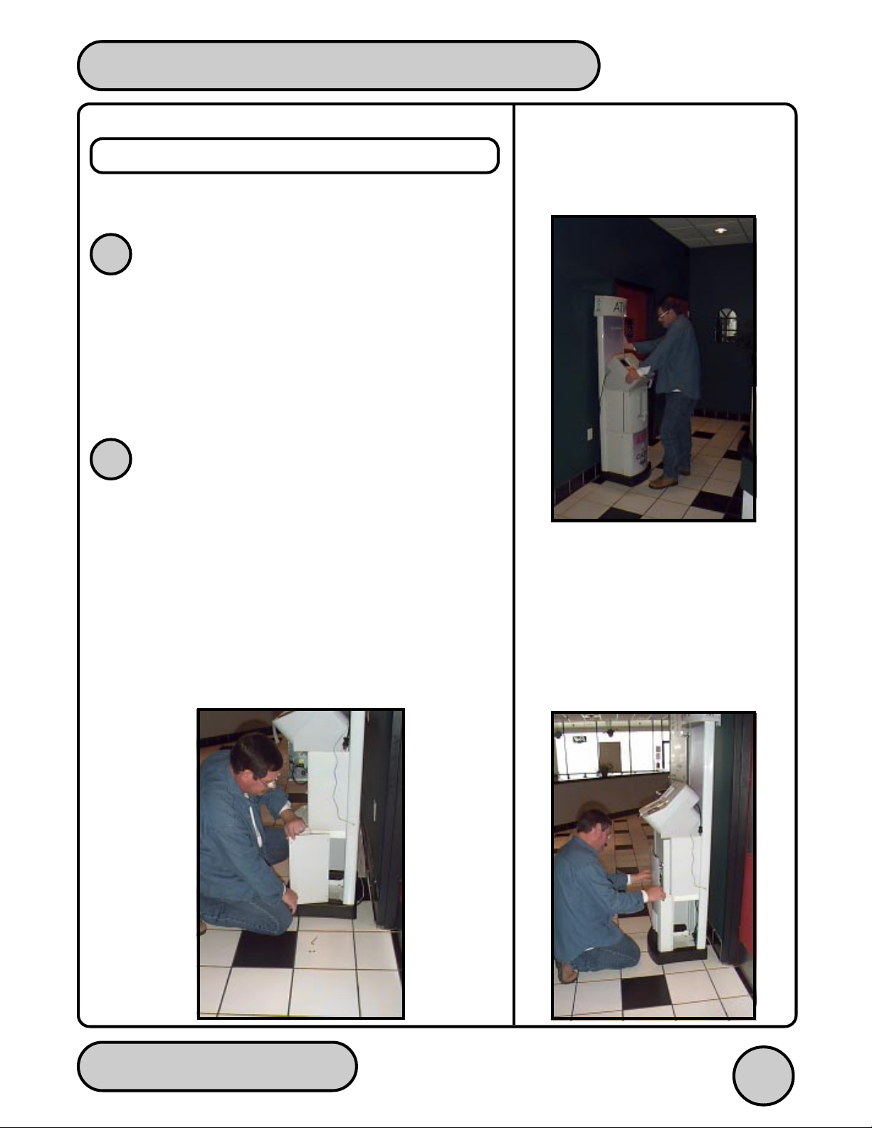
Follow these steps to install the Mako unit:
DETERMINE PEDESTAL LOCATION
1
Move the pedestal assembly to the location where it
will be installed (See Figure 1). Ensure there are no
obstructions that would prevent access to the interior of
the lower pedestal enclosure (you will be removing the
front panel and one of the side panels in the next step).
REMOVE LOWER ENCLOSURE PANELS
2
Select one of the side panels for removal. Using the
provided torx-key tool, remove the two tamper-resistant fasteners that secure the selected side panel to the
pedestal frame. Tilt and slide the panel out of its slotted
supports. (See Figure 2)
Open the door of the security cabinet and slide the front
panel(and optional graphics panel, if installed) up and
out of the slotted supports. (See Figure 3)
Fig. 2
Fig. 1
Fig. 3
TRITON SYSTEMS, INC.
3
Page 4

MAKO CASH DISPENSER PEDESTAL INSTALLATION GUIDE
LEVEL THE CABINET
3
Use a screwdriver to screw all four leveling feet in so
they are flush with the bottom of the cabinet.Use a
bubble level to check the leveling (Figure 4). If necessary , adjust one or more of the feet slightly to achieve a
level base (Figure 5),
bottom of the cabinet as possible
cabinet should be resting evenly on all four feet, and
should not rock or tilt in any direction.
keeping the feet as close to the
. When done, the
Leveling Foot
Fig. 5
DRILL PEDESTAL MOUNTING HOLES
4
Locate the four hole-cutouts in the metal frame of the
pedestal base and use them to mark the drilling points
for the pedestal mounting holes.
If the optional security chain is to be installed, place any
one of the chain-anchor plates inside the large cutout in
the center of the enclosure floor. Center the plate between the left and right sides of the cutout, then push
the plate to the back edge of the cutout, as shown in
Figure 6. Mark the drilling points for the chain anchor
plates, which will be installed in a later step.
Close the security cabinet door and move the pedestal
(and chain anchor plate) aside to provide clear access
to the mounting-hole pattern. Drill four 1/2" holes, at least
three inches deep, into the concrete flooring at the pedestal base locations marked earlier. Next, drill each hole
to a depth of two inches, using a 3/4" bit. (See Figure 7)
Fig. 4
Fig. 6
Fig. 7
TRITON SYSTEMS, INC.
4
Page 5

MAKO CASH DISPENSER PEDESTAL INSTALLATION GUIDE
If the optional security chain is being installed, drill four,
3/8" holes at least three inches deep, into the concrete
flooring at the anchor plate positions marked earlier.
INSTALL OPTIONAL SECURITY CHAIN
5
ANCHOR
Dowel Rod
Mounting
Stakes
Dowel
1/4” Screws,
Nuts, and
Washers 2 ea.
Pin
Bracket
Fig. 8
“Plus” Plates (3)
Security Chain
“Minus” Plates (3)
Ring Pin
The components of the optional security chain installation kit are shown in Figure 8.
Assemble two stacks of chain anchor plates. First, assemble a stack using the three “plus” plates and set
aside. Next, place two (NOT THREE) “minus” plates
together, ensuring the slots are aligned in the same direction, and place one of the end links of the chain partially through this slot. (Figure 9)
Fig. 9
Use Only TWO “MINUS” Plates!
Fig. 10
Use THREE “PLUS” Plates.
Slip the short metal dowel rod through the loop in the
chain, as shown, and hold the assembly so that the chain
is held in position. Finally, place the stack of “minus”
plates (with the attached chain) on top of the stack of
“plus” plates, aligning the slots so that the two parts fit
together, forming a single stack. (Figure 10)
When moving the plates (as directed in the next step)
be sure to keep a firm hold on the stack as you move it
into position.
TRITON SYSTEMS, INC.
Fig. 11
5
Page 6

MAKO CASH DISPENSER PEDESTAL INSTALLATION GUIDE
Place the stack of chain-mounting plates into position
for mounting. Align the corner holes of the stack with
the mounting holes you previously drilled. Place a
mounting stake through each corner hole. Each stake
should pass completely through the plate stack and fit
into the mounting hole. (Figure 11)
Hammer the stakes into the flooring (See Figure 12).
Bunch the chain into a bundle around the plate (this will
make it easier to place the pedestal into its final mounting position).
INSTALL THE PEDESTAL
6
Fig. 12
Place the four provided 3/4" expansion inserts into the
pedestal mounting holes that were drilled previously.
The threaded end of each insert should be inserted first.
If necessary, tap the inserts into the holes with a hammer (not provided) to ensure they are flush with the surface of the floor.
Move the pedestal back into position for mounting. It
may be necessary to tilt the unit slightly to clear the
security chain. Align the mounting-hole cutouts in the
pedestal base with the mounting holes.
Insert a 3/8" security bolt through a provided washer
and into each insert. Using a 5/16" socket and wrench
(not provided) and the special “pin-in-torx” bit (provided),
firmly tighten the bolts into the inserts to secure the pedestal to the floor.
Locate the unit’s phone and power cables in the pedestal base and route the cables through the “mouse” hole
cutout in the base.
TRITON SYSTEMS, INC.
6
Page 7

MAKO CASH DISPENSER PEDESTAL INSTALLATION GUIDE
ATTACH OPTIONAL SECURITY CHAIN
7
TO VAULT
Open the security container door. Note the pre-drilled
mounting holes in the floor of the container (Figure 13).
These holes will be used to attach the top mounting
plate and bracket assembly for the security chain.
Place the remaining “minus” plate into position, aligning it with the mounting holes and ensuring the slot is
oriented vertically, as shown in Figure 14.
Place the pin bracket into position. Secure it to the
mounting plate and security cabinet floor using the two
1/4" screws, nuts and washers (provided), as shown in
Figure 15. Reach into the lower enclosure to feed the
nuts onto the screw threads. Use a 1/4” nut driver or
“Minus” Plate in Mounting Position
socket wrench to tighten the screws down firmly.
Mounting Holes
Fig. 13
Reach into the lower enclosure and feed the link at the
free end of the security chain up through the slot in the
pin bracket. Insert the ring pin completely through the
bracket and chain link. The pin should lock into place.
(See Figure 16)
Chain End-Link
Ring Pin Fully Inserted
Fig. 16
This completes the installation of the optional security
chain.
Fig. 14
Mounting Screws
Fig. 15
Pin Bracket
TRITON SYSTEMS, INC.
7
Page 8

MAKO CASH DISPENSER PEDESTAL INSTALLATION GUIDE
REPLACE LOWER ENCLOSURE PANELS
8
Replace the front and side panels you removed previously. (Figure 17)
Store the installation bit and key by attaching them to
the magnet on the wall of the security cabinet (as in
Figure 18). Close the security container door. Physical
installation of the Mako pedestal is complete.
Fig. 18
Fig. 17
TRITON SYSTEMS, INC.
8
 Loading...