

MAKO® EC
EXTENDED CABINET
INSTALLATION GUIDE
VERSION 2.0
TDN 07102-00033 03/01
CORPORATE HEADQUARTERS: RMA (RETURN MATERIAL AUTHORIZATION)
RETURN ADDRESS:
522 E. Railroad Street 21405 B Street
Long Beach, MS 39560 Long Beach, MS 39560
PHONE: (228) 868-1317
FAX: (228) 868-0437
COPYRIGHT NOTICE
Copyright © 2001 Triton Systems , Inc. All rights reserved. No part of this publication may be
reproduced, transmitted, transcribed, stored in a retrieval system, or translated into any human or computer language, in any form, by any means whatsoever, without the express
written permission of Triton Systems, Inc.
MAKO is a registered trademark of Triton Systems, Inc.
MAKO EC EXTENDED CABINET INSTALLATION GUIDE
SELECTING THE
INSTALLATION
LOCATION
Choosing the right location for your
Cash Dispenser is very important.
Security concerns suggest a location be chosen that is away from any
door or external access point. Ideally , the terminal should be mounted
as close to a back wall as possible.
For marketing reasons, however, it
may be desirable to locate the terminal near the front of your establishment, where your customers
can easily locate it. Wherever you
decide to locate the terminal, be
sure to follow the recommended
procedures for both mounting the
terminal and for removing cash from
it when the unit will be unattended.
DEILPPUSSTRAP
4srohcnAnoisnapxE"4/34srehsaWtalF
4
xeH,57.1x61-"8/3
stloB
4srehsaWkcoL
110001-57030rebmuNtraP,etalpmeTllirD
TNEMPIUQE/SLOOTDERIUQER
1
cirtcelEytuD-yvaeH
llirDremmaH
1
.ae
stiBllirD"4/3,"4/1
1selggoGytefaS1
sffuMrosgulPraE
)noitcetorpgniraeh(
1tleBtroppuS-kcaB1
muucaVelbatroP
renaelC
1tekcoS"61/9
deriuqersi)sdnuop-toof03foelbapac(hcnerweuqrotA
ehtfoesuaceB.stlobgnitnuomtenibacehtnethgitot
sislootfoeciohcehttenibacehtedisniecapsdetimil
detsilera)Cdna,B,A(sevitanretlaeerhT.tnatropmi
.ecnereferpforedroni,woleb
A
elbapac(hcnerWeuqroT
-toof03tsaeltafo
)sdnuop
ehteraesehT derreferp sloot
ehtgninethgitnehwesuot
.stlobgnitnuomtenibac
A
raBnoisnetxEtekcoS
)gnolsehcni12tsaelta(
B
ssel(hcnerWeuqroT
)gnolsehcni-11naht
nafisihtesU rabnoisnetxe
.elbaliavanusi
C
ssel(hcnerWdradnatS
dna)gnolsehcni-11naht
gnitimil-euqroTa
tnemhcatta
afisihtesU hcnerweuqrot
signolsehcni-11nahtssel
.elbaliavanu
Observe ALL safety precautions for
operating hand and power tools!
Wear eye and ear protection while
operating the electric drill!
USE A BACK-SUPPORT BELT
WHEN LIFTING AND MOVING
THE CASH DISPENSER!
TOOL USE/SAFETY
TRITON SYSTEMS, INC.
2
MAKO EC EXTENDED CABINET INSTALLATION GUIDE
UNPACK CASH DISPENSER
**IMPORTANT**
The Cash Dispenser is designed for indoor installation only!
Retaining Screws
1. Carefully inspect the unit for any shipping damage and report
any damage immediately to the shipping company . Refer to
the Warranty Information in the operation or service manual
(as applicable) for information about reporting shipping
damage.
2. Remove the unit from the carton by cutting the straps and
removing the top of the box.
3. Remove the loose packing material from inside of the box.
4. Remove the Accessory Kit, which is attached to the front of
the advertising/light panel.
5. Remove the silver key from the white plastic bag attached to
the Cash Dispenser wrapping.
6. Stand the unit up.
7. “Walk” the unit out of the carton and remove the protective
plastic bag.
8. Use the silver-colored key to unlock both the Control Panel
and the Fascia door (which conceals the locking mechanism)
on the front of the cabinet. Open the Fascia door.
9. Turn the handle on the locking mechanism to open the cabinet
door. Open the door at least 90-degrees to improve access.
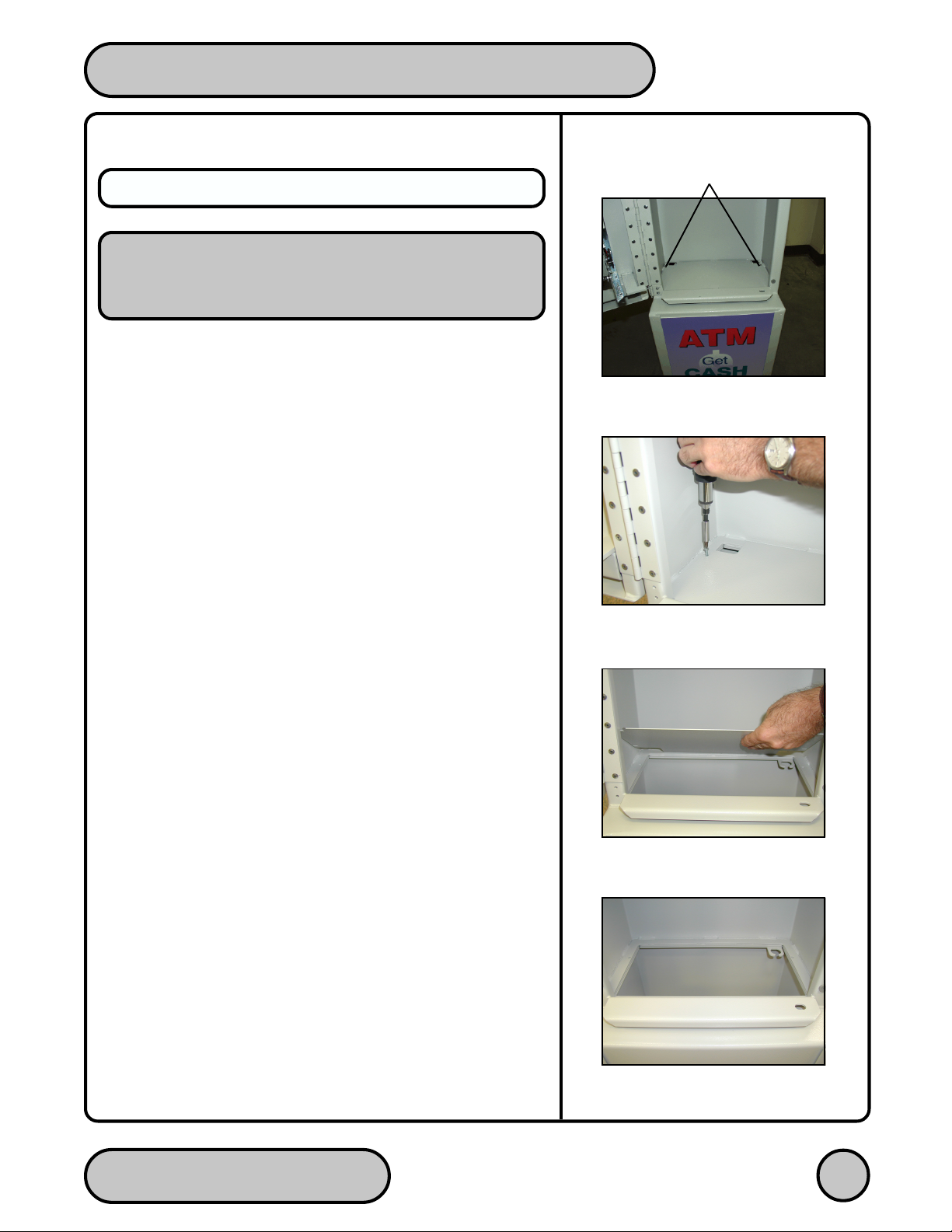
Fig. 1. Floor-Plate In Place.
Fig. 2. Unscrewing Retaining Screws.
Fig. 3. Floor-Plate Lifted.
10. Unscrew the two retaining screws that secure the metal floor
plate to the bottom of the cabinet. Lift out the floor-plate, as
shown in Figures 1 through 4.
TRITON SYSTEMS, INC.
Fig. 4. Floor-Plate Removed.
3

MAKO EC EXTENDED CABINET INSTALLATION GUIDE
MARK/DRILL MOUNTING HOLES
CONCRETE STRENGTH
The floor at the installation location should consist of commercial-grade concrete, measuring at least 3000 psi in compression strength. The full effectiveness of the anchor
bolts depends upon meeting this specification! Check
with the contractor/builder or owner of the installation to verify
that this requirement can be satisfied.
Mark the location of the cabinet mounting holes on the concrete
flooring. This can be accomplished in two ways, as described below:
Anchor-Bolt Holes
1a. Preferred Method. Place the included mounting hole drilling
template on the floor in the designated location and tape it into
position. Be certain there are no physical obstructions that
could prevent the cabinet from being installed in this
location, or otherwise limit access to the unit!
Use a center punch tool (or equivalent) to mark the center of
each mounting hole, as indicated on the template. Use a felttip pen or other marker to carefully mark the front corners of
the cabinet. These marks will serve as guides to align the
cabinet in the final mounting position. Remove the template.
Figure 11 provides an example (not to scale) of the template.
1b. Alternative Method. Move the Cash Dispenser to the location
where it will be installed.
Locate the four anchor-bolt holes in the bottom of the cabinet
(see Figure 5). Use a felt-tip pen or other marker to carefully
mark the center of each of these four holes on the floor and
the front corners of the cabinet. These marks will serve as
guides to align the cabinet properly when it is moved into the
final mounting position.
Move the Cash Dispenser aside, to provide clear access to
the mounting hole marks.
Fig. 5. Lower Cabinet Bottom.
Fig. 6. Drill Pilot Hole.
TRITON SYSTEMS, INC.
4

MAKO EC EXTENDED CABINET INSTALLATION GUIDE
**IMPORTANT**
Use a pencil or measuring rod to check the depth of each
hole; the depth of each hole must be at least 1 3/4 inches
before continuing!
2. Use a 1/4-inch diameter carbide-tipped masonry bit to drill four
pilot holes at the drilling points marked in the previous step.
Drill the pilot holes approximately 1/2-inch deep into the floor.
See Figure 6. These holes will help guide the 3/4-inch masonry
bit that will be used to drill the anchor-bolt holes in the next
step.
3. Use a 3/4-inch diameter carbide-tipped masonry bit to drill four
holes at least 1 3/4 inches deep into the floor. See Figure 7.
Be sure to take into account the depth of any floor covering,
such as tile, carpet, or vinyl when gauging the depth of the
anchor holes. Make sure the holes are drilled at least 1 3/4
inches into the concrete floor.
Fig. 7. Drill Anchor Hole.
5. Use a portable vacuum cleaner to remove any dust or debris
that may have accumulated in the holes during the drilling
process.
BOLT CASH DISPENSER TO FLOOR
1. Note the two cone-shaped wedges at either end of the expan-
sion anchor; one cone has a threaded bore. Place the four
provided 3/4" expansion anchors into the mounting holes that
were drilled previously, threaded ends first.
2. See Figure 8. The top of the expansion anchor sleeve must be
flush with the mounting surface. The top cone-wedge will project
slightly above the mounting surface, as shown.
Fig. 8. Insert Expansion Anchor.
TRITON SYSTEMS, INC.
5

MAKO EC EXTENDED CABINET INSTALLATION GUIDE
3. Move the pedestal back into position for mounting. Align the
mounting-hole cutouts in the pedestal base with the mounting
holes.
4. Insert a 3/8-inch security bolt through a provided lock washer,
flat washer and into each insert. Att ach a 9/16-inch socket to a
torque wrench and tighten each bolt to a setting of 30 foot-
pounds. Because of the limited access in the lower cabinet
area, consider the following three alternative methods of
reaching the mounting bolts:
a. (Preferred method) Use a wrench with an extension bar at
least 21 inches long to move the wrench outside the lower
cabinet area. Figure 9 provides an example of this approach.
b. Use a torque wrench shorter than 11 inches to reach into
the lower cabinet area to access the bolts.
c. Use a short (less than 11 inches) standard wrench
equipped with a torque-limiting attachment to reach into
the lower cabinet area to access the bolts.
5. See Figure 10. Once the bolts are tightened down as specified
in the previous step, replace the metal floor plate that was removed
earlier. Secure the plate in place using the two ret aining screws.
6. The installation of the Cash Dispenser cabinet is complete.
Fig. 9. Tightening Anchor Bolts
(Preferred Method).
Fig. 10. Anchor Bolt Installed.
TRITON SYSTEMS, INC.
6

MAKO EC EXTENDED CABINET INSTALLATION GUIDE
Fig. 11. Mounting Hole Drill Template Example (Not to Scale).
TRITON SYSTEMS, INC.
7
 Loading...