

Page 1
INSTALLERS PLEASE NOTE THESE INSTRUCTIONS ARE TO BE LEFT WITH THE USER
2180514G June 2008
Installation and
operating
instructions
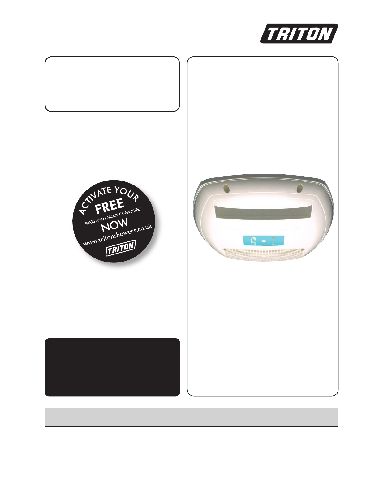
Luxury
body dryer
Page 2
the nation’s favourite for
PLUMBING & HEATING SUPPLIES
SECURE PAYMENTS
shop online with confidence
FREE SHIPPING
on all orders over £100 to mainland UK
FINANCE AVAILABLE
spread the cost with low interest rates
PRICE MATCH
always get the best deals available
Boilers
Radiators
Heating controls
Cylinders
Fires
Renewable energy
Bathroom suites
Kitchen sinks & taps
Showers
Wet rooms
Towel warmers
Bathroom furniture
& much more
HUGE REDUCTIONS
we have
ON THOUSANDS OF ITEMS
0844 800 3460
CALL US ON
visit our website
plumbnation.co.uk
Page 3

Body dryer
ii
CONTENTS Page
Important safety information........................................ 1
Introduction ................................................................. 2
Specifications ............................................................... 2
Advice to users ............................................................. 2
Fault finding ................................................................ 3
Key to main components ............................................. 3
Electrical requirements ................................................. 4
Siting ........................................................................ 6
Fitting the body dryer .................................................. 8
Electrical connections .................................................. 10
Replacing the cover .................................................... 12
Commissioning ........................................................... 13
Operating functions .................................................... 14
Overheat cut out ........................................................ 15
Cleaning ..................................................................... 16
Servicing ..................................................................... 16
Spare parts ................................................................. 17
Guarantee, service policy, etc. ................................ rear cover
To check the product suitability for commercial and multiple installations, please contact Triton’s
specification advisory service before installation.
Telephone:
Facsimile:
E mail:
0870 067 3767
0870 067 3334
technical@tritonshowers.co.uk
Page 4

Body dryer
1
1 GENERAL
1.1 Isolate the electrical supply before removing
the cover.
1.2 Read all of these instructions and retain
them for later use.
1.3 DO NOT take risks with plumbing or
electrical equipment.
1.4 Isolate electrical supplies BEFORE proceeding
with the installation.
1.5 Contact Customer Service (see back page)
if the unit shows a distinct change in
performance.
1.6 The mesh grill on the air inlet should be
regularly inspected for any build up of fluff
and cleaned if found.
1.7 This product is not suitable for mounting
into shower cubicles, steam rooms or steam
cubicles.
1.8 To enable future servicing to be carried out
on the unit:
a) When installed in a loft space the body
dryer must be sited in an accessible and safe
location.
b) A safe means of access must be provided
into the loft e.g. fixed loft ladder.
c) Ceiling joists in the loft must be adequately
boarded to provide safe unobstructed access
to and around the body dryer.
d) There must be adequate lighting in the
loft for servicing purposes.
2 ELECTRICAL
2.1 The electrical installation must comply
with BS7671 ‘Requirements for electrical
installations” (IEE wiring regulations),
Building Regulations or any particular
regulations as specified by the local Electrical
Supply Company.
2.2 The appliance and any associated electric
shower MUST be earthed using the main
feed earth wire connections provided in the
appliances.
2.3 In accordance with ‘The Plugs and Sockets,
etc (Safety) Regulations 1994’, this appliance
is intended to be permanently connected
to the fixed wiring of the electrical mains
system.
2.4 Make sure all electrical connections are tight
to prevent overheating.
2.5 Fuses DO NOT provide personal protection
against electric shock.
2.6 To enhance electrical safety a 30mA residual
current device (RCD) MUST be installed in
all body dryer/shower circuits. This may be
part of a consumer unit or a separate circuit.
2.7 Switch off the unit immediately at the pull
cord isolation switch if the unit comes into
contact with water. DO NOT reconnect until
a qualified electrician has checked the unit
for safety.
2.8 The unit is designed to work in association
with an instantaneous electric shower where
the circuit protective device (fuse) is 40A or
45A rating. No other electrical equipment
i.e. extractor fans or pumps should be
connected to the body dryer unit.
2.9 Always electrically isolate the dryer or
dryer/shower combination at the pull cord
isolation switch when not in use. This is a
safety procedure recommended with all
electrical appliances.
2.10 As with all electrical appliances it is
recommended to have the body dryer
and any associated shower unit installation
checked at least every two years by a
competent electrician to make sure there is
no deterioration due to age and usage.
PLEASE READ THIS IMPORTANT SAFETY INFORMATION
F Products manufactured by Triton are safe and without risk provided they are installed, used and
maintained in good working order in accordance with our instructions and recommendations.
F All required safety features have been designed and built into the product for your complete protection.
F WARNING: Always isolate electrically the dryer or dryer/shower combination when not in
use. This is a safety procedure recommended with all electrical appliances.
F The dryer has been designed for use in a bathroom or shower room for the purpose of personal
body drying and will heat a bathroom rapidly. The dryer should not be used for any other purpose.
This dryer MUST NOT be installed directly above a bath or within a shower cubicle. It MUST
be sited as shown in Fig.3. on Page 6 of these instructions.
Page 5

Body dryer
2
INTRODUCTION
This book contains all the necessary fitting and
operating instructions for your Triton Luxury
Body Dryer. Please read them carefully.
The Body Dryer installation must be carried
out by a suitably qualified person and in the
sequence of this instruction book.
Care taken during the installation will provide a
long, trouble-free life from your body dryer.
The Body Dryer has been designed for use in a
bathroom or shower room for the purpose of
personal body drying. The dryer should not be
used for any other purpose.
Never install in a shower cubicle or steam
room.
SPECIFICATIONS
Electrical
Nominal power Nominal power
rating at 240V rating at 230V
9.0kW – (40A MCB rating) 8.3kW – (40A MCB rating)
Trickle current on OFF mode is 0.04A at 240V
(9.6W) but is not isolated.
Minimum cross sectional area of supply cable is
6mm². Derating factors should always be taken
into consideration when selecting cable size.
Materials
Main unit – 20% Glass filled Polypropylene
Cover – ABS
Dimensions
Width – 335mm, Length – 625mm,
Height – 175mm
Above ceiling – 140mm
Below ceiling – 70mm (cover)
Weight – 7kg
Packed weight – 10kg
Standards and Approvals
Complies with requirements of current British
and European safety standards for household
and similar electrical appliances.
Complies with requirements of the British
Electrotechnical Approvals Board BEAB.
Meets with compliance with European
Community Directives CE. EMC
ADVICE TO USERS
The following points will help you understand
how the Body Dryer operates:
a. The unit consists of a high powered two
speed fan and 2 x 4.5kW heater elements
which are fully controllable using the hand-held
controller (supplied). Air is drawn in through
the filter, passed across the elements and then
discharged downwards.
b. DO NOT place pressurised aerosol cans in or
under the hot air flow. Always electrically isolate
the dryer or dryer/shower combination when
not in use.
c. Temperature sensors are fitted to the unit for
your safety. However, the best sensor is you. If
you find the airflow or room temperature rises
to uncomfortable levels switch off or regulate
the flow through use of the controller. Never
leave alone those unable to recognise or react to
discomfort with the dryer switched on.
For ideal comfort and drying time the ceiling
height should be between 2.2m to 2.5m.
The dryer has a 10-minute preset cut off.
d. The unit can be connected in combination
with an electrical shower rated from 8kW
up to 10.5kW. The electrical safety features
incorporated in the unit do not allow the Body
Dryer to be operated while the shower is on and
vice versa.
e. The hand-held controller should be kept
away from sources of water.
f. The LED’s incorporated into the cover show
the operational status of the Body Dryer or
any fault condition. If you suspect the unit to
be faulty unqualified attempts to rectify the
situation should be limited to isolating and
switching on the unit via the pull cord and
operation of the hand-held controller (see
commissioning instructions). All other problems
MUST be attended to by a competent electrician
or service engineer.
Due to continuous improvement and updating,
specification may be altered without prior notice.
Replacement parts can be ordered from Customer
Service. See ‘spare parts’ for details and part numbers.
Page 6
Body dryer
3
Fig.1
FAULT FINDING
Follow the instructions for commissioning. If
findings do not match expectations contact
Triton Customer Service.
If the green LED is on but the unit does not
operate then the hand-held controller or its
battery should be suspected.
DO NOT attempt any repairs since
there are no user serviceable parts in
the unit.
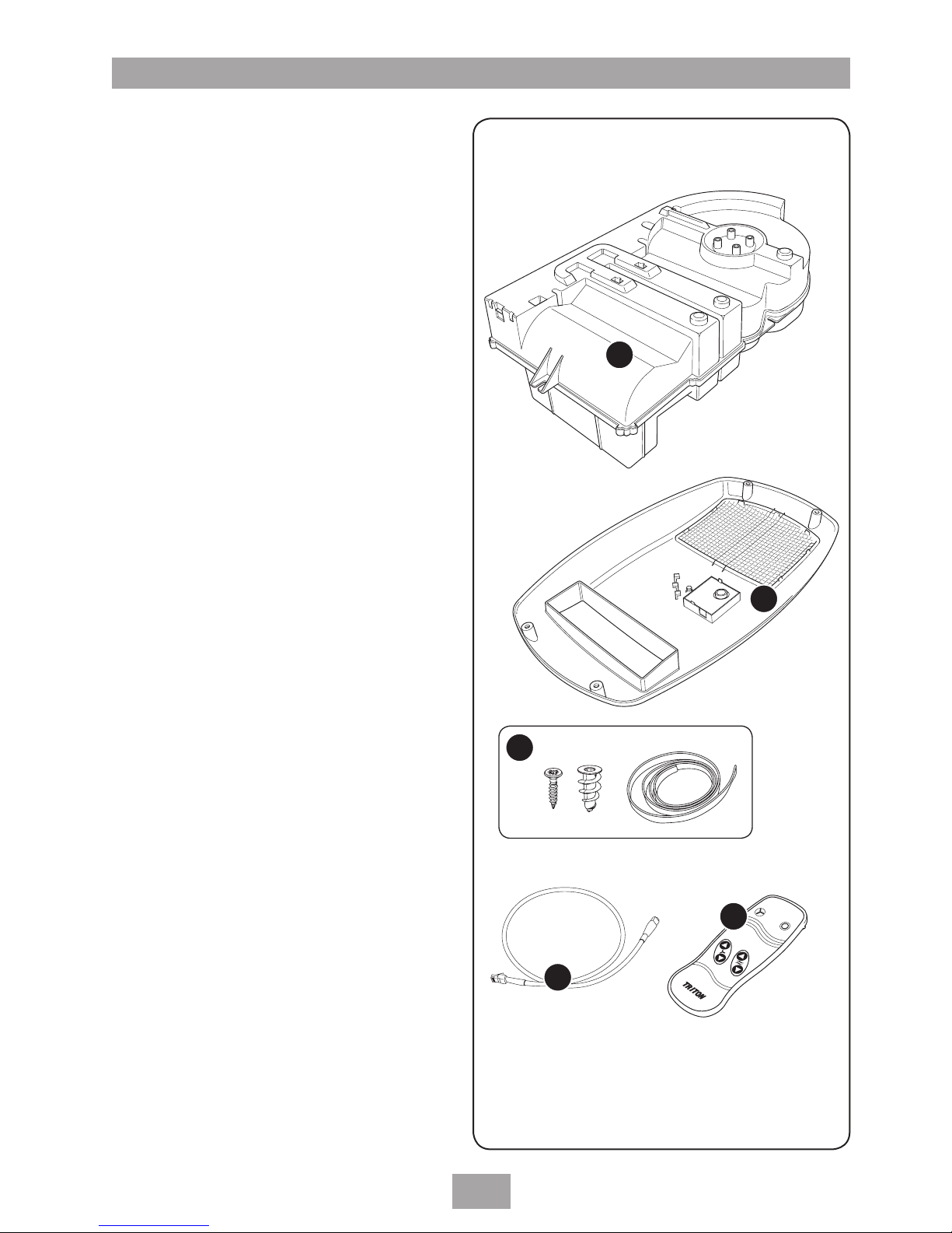
KEY TO MAIN COMPONENTS
1. Body dryer unit
2. Front cover
3. Fixing kit
4. Communications cable
5. Remote control
6. User guide (not shown)
1
2
4
3
5
Page 7
Body dryer
4
ELECTRICAL REQUIREMENTS
The installation, supply cable and circuit
protection must conform with BS7671 (IEE
wiring regulations) and be sufficient for the
amperage required.
The following notes are for guidance only:
1 The body dryer must only be connected to
a 230 – 240V ac supply (single phase).
2 If an instantaneous electric shower
circuit already exists the body dryer
may be connected in series with the
shower subject to confirmation that the
electrical circuit complies with current IEE
regulations.
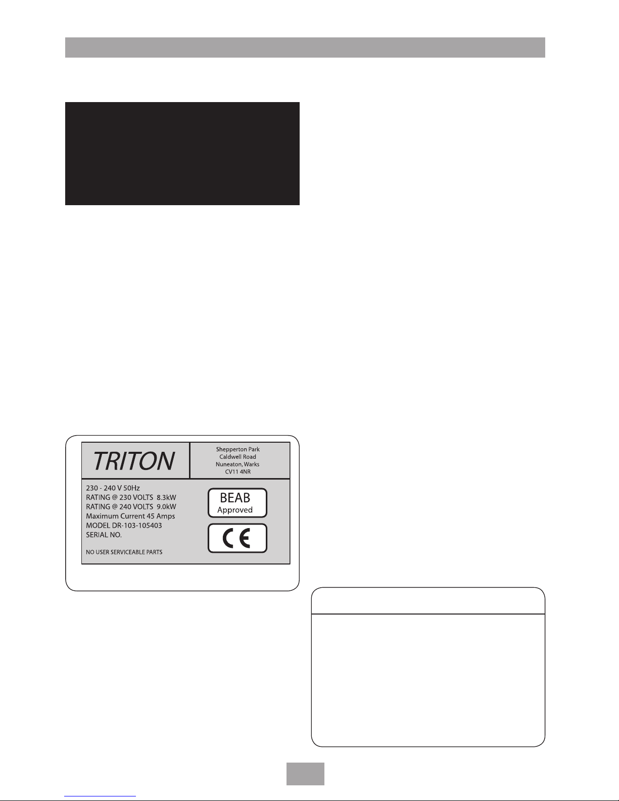
2.1 The electrical rating of the body dryer is
shown on the rating label within the unit.
3 Before making any electrical connection
within the installation make sure that no
terminal is live. If in any doubt switch off
the whole installation at the mains and
remove the correct circuit fuse.
4 If the installation is undertaken by
anyone who is not registered to issue
a Part P electrical certificate then it will
be necessary to notify the local Building
Control office before installing.
5 The body dryer must be connected to
its own independent electrical circuit as
determined by the IEE regulations but it
can share the same supply as an electric
shower providing the wiring connections
follow that of the wiring schematic shown
in the electrical connections section.
The body dryer MUST NOT be connected
to a ring main, spur socket outlet, lighting
circuit or cooker circuit.
Note: Safety features built into the body
dryer prevent the unit and any shower fed
via the body dryer from operating at the
same time.
5.1 The electrical supply must be adequate for
the maximum loading of the unit and/or
any existing shower circuit.
6 Check the consumer unit (main fuse
box) has a main switch rating of 80A or
above and that the fuse way will take the
necessary fuse or MCB to provide the
maximum electrical load (amps) of the
body dryer and shower if applicable.
6.1 If the consumer unit has a rating below
80A or there is no spare fuse way then the
installation may require a new consumer
unit serving the house or just the body
dryer/shower.
6.2 If you do not have the necessary supply
you will need to contact the local
electricity company regarding upgrading
the incoming supply.
Table A
Fig.2
WARNING!
WHEN USED INDEPENDENTLY OR IN
TANDEM WITH AN ELECTRIC SHOWER
THIS APPLIANCE MUST BE EARTHED
(EARTH CONTINUITY MUST BE
MAINTAINED).
CIRCUIT PROTECTION
unit cartridge
rating MCB fuse
8.0kW 40A 35A
8.5kW 40A 45A
9.0kW 40A 45A
9.5kW 40/45A 45A
10.5kW 45A 45A
Page 8

Body dryer
5
7 The earth continuity conductor of the
electrical installation must be effectively
connected electrically to all exposed metal
parts of other appliances and services in
the room in which the body dryer and
an electric shower is to be installed, to
conform to current IEE regulations.
8. For close circuit protection DO NOT use
a rewireable fuse, instead use a suitably
rated miniature circuit breaker (MCB) or
cartridge fuse (see table A).
8.1 A 30mA residual current device (RCD)
MUST be installed in wiring for all body
dryer installations.
9 A 45 amp double pole isolating switch
with a minimum contact gap of 3mm in
both poles must be incorporated in the
circuit.
9.1 This isolating switch must also have a
mechanical indicator showing when the
switch is in the OFF position and the
wiring must be connected to the switch
without the use of a plug or socket outlet.
9.2 The switch must be accessible and clearly
identifiable, but out of reach of a person
using a fixed bath or shower, except for
the cord of a cord operated switch. The
switch should be placed so that it is not
possible to touch the switch body while
standing in the bath or shower cubicle. It
should, however, be readily accessible to
switch off after using the shower.
10 Where a shower cubicle is located in any
room other than a bathroom, all socket
outlets in that room must be protected by
a 30mA RCD.
11 The current carrying capacity of the cable
must be at least that of the shower circuit
protection.
11.1 To obtain full advantage of the power
provided by the body dryer, use the
shortest cable route possible from the
consumer unit to the body dryer and to
the shower if applicable.
11.2 It is also necessary to satisfy the
disconnection time and thermal
constraints, which means that for any
given combination of current demand,
voltage drop and cable size, there is a
maximum permissible circuit length.
12 The body dryer circuit should be separated
from other circuits by at least twice the
diameter of the cable or conduit.
12.1 The current rating will be reduced if
the cabling is bunched with others,
or surrounded by thermal loft or wall
insulation or placed in areas where the
ambient temperature is above 30°C.
Under these conditions derating factors
apply and it is necessary to select a larger
cable size.
12.2 In the majority of installations the cable
will unavoidably be placed in one or more
of the above conditions. This being so, we
strongly recommend using a minimum of
10mm² cabling throughout the installation.
12.3 In any event, it is essential that a
competent electrician assess individual site
conditions in order to ensure the correct
requirements are met.
Page 9

Body dryer
6
SITING
Consumer unit
Body dryer
Shower
unit
2.2 - 2.5 metres
Isolating
switch
Fig.4 Typical system layout
The dryer has been designed for use in a
bathroom or shower room for the purpose of
personal body drying and will heat a bathroom
rapidly. The dryer should not be used for any
other purpose (It may be sited in Area C or
beyond defined areas); see fig.3.
WARNING!
The dryer must NOT be positioned
where it is likely to become in contact
with water from above or below or
in a damp environment e.g. inside a
steam room, shower cubicle or directly
over a bath in Area A or B - see fig.3.
Beyond defined Areas
Fig.3
Page 10

Body dryer
7
600mm diameter
Before installing consideration should be given
to ease of installation, inspection, servicing and
removal.
Access to electrical connections and the routing
and security of electrical cables should always be
paramount, particularly the isolation switch (see
Electrical Requirements).
Fig.4 shows a typical system layout.
As a minimum, a floor area of 600mm diameter
should be allowed directly below the output
vent (rectangular nozzle) of the body dryer for
the user to stand in (fig.5). However, the user
will benefit most where the area under the dryer
is the largest area possible of clear floor space.
Note: The body dryer MUST not be positioned
over a bath or within a shower cabinet.
Use the template (fig.6) and cover to
determine the best position for the body dryer.
Careful observation and measurement both
above and below the ceiling will ensure all
factors are taken into account before any drilling
or cutting takes place.
Always try the body dryer template in a selected
location before proceeding further.
IMPORTANT: Loft insulation that occupies
the space required for the dryer should be
removed or rolled back. The unit must be
installed on flat surfaces both above and
below the ceiling otherwise difficulty may be
encountered when fitting the ceiling cowling
and subsequent operation of the unit may be
impaired.
Note: To install the Body Dryer to a concrete
ceiling with an additional suspended ceiling or
a bathroom with a timber flat roof construction
you will need to use an optional fitting kit (not
supplied). Contact Triton Customer Service for
further details.
Once installed, care should be taken to ensure
the immediate area around the body dryer
unit within the loft space remains a clear of of
obstructions and that other items are not placed
against the unit or in close proximity.
It is recommended that the electrical feed cables
are secured to a convenient joist (fig.7).
Perforated line
E
B
D
C
B
A
B
Perforated Line
Minimum gap between joists
with template folded (350mm)
E
B
D
C
B
A
B
Fig.5
Fig.6
Secure
the cables
to joist
Fig.7
Key
A. Air intake.
B. Bolt hole for solid
ceiling.
C. Communications
cable hole.
D. Water drainage.
E. Exhaust nozzle.
Page 11

Body dryer
8
20mm
diameter
FITTING OF THE DRYER
Before installation check the parts for any signs
of obvious damage.
Read, understand and follow the installation
safety guidelines that come with this product.
The dryer has been designed for use in a
bathroom or shower room for the purpose of
personal body drying. The dryer should NOT be
used for any other purpose; see 'Siting'.
Parts check list
Hand-held controller and battery (3V Lithium
12032)
Main unit
Ceiling cover
Template
Support straps and staples
Ceiling fittings
Tools required
Electrical test meters
Small bradawl/small screwdriver
Marker pen/pencil and straight edge
Pad saw
Crosshead screwdriver
Flat head screwdriver
Hand-held drill with 8mm drill bit
Protective goggles/glasses and face mask
Procedure
Use the template and cover to determine
the best position for the body dryer. Careful
observation and measurement both above and
below the ceiling will ensure all factors are taken
into account before any marking, drilling or
cutting, takes place.
If the template does not fit easily between the
roof joists then a section of joist may have to be
removed and the remainder supported by cross
members attached to the adjacent joists with
suitable supports on either side of the unit.
IMPORTANT: This task is beyond the scope
of this book and should NOT be attempted
unless the installer is suitably experienced
and has the knowledge and skills to maintain
a secure structure.
The minimum distance between joists is 355mm.
Fig.8
Fig.9
Fig.10
Page 12

Body dryer
9
Tip: Remember, sound advice is to measure
twice, cut once.
Note: The cut-outs in the template are not
symmetrical about the centre of the template.
When positioning the template make sure to use
the correct aspect.
Place the template supplied in the selected
position in the roof space and push a bradawl
or thin screwdriver through the plasterboard to
mark the four corners of the rectangular cut out,
the centre of the round hole and the centres
of the two smaller holes (fig.8). Remember,
you are pushing through plasterboard and the
minimum effort required should be used.
From below, line up the template with the holes
made in the ceiling and mark the cut outs and
cover locating holes with a pen (fig.9).
Before making any cuts align the cover to these
markings to confirm the chosen position.
Drill the four corners of the rectangular cut out
and one point on the inner edge of the large
round hole with an 8mm drill bit to allow for a
pad saw to be used (fig.10). Open out the two
smaller holes to 20mm diameter.
When drilling or cutting from below it is
recommended that eye protection is used.
Waste material should be collected at the
highest convenient point since airborne particles
can cause respiratory discomfort. A vacuum
cleaner nozzle close to the drill bit or pad saw
cut can also reduce the overall volume.
It is useful to have an assistant when drilling or
cutting the plaster board to hold a catchment
tray or box for the falling debris. Do not forget
that they need personal protection too.
Clear out any debris that remains above ceiling
height.
Position the body dryer from above (fig.11)
and inspect from below. Fit temporarily the
cover to confirm correct fit and alignment.
Support the unit between the joists using the
support straps and staples provided (fig.12).
The straps need only be slightly tensioned.
Connect the communications cable to the body
dryer unit (fig.13) and route the cable through
the hole in the plasterboard in preparation for
plugging into cover (fig.13).
Support
straps
Fig.12
Fig.11
Feed
communication
cable through
hole in ceiling
Fig.13
Page 13

Body dryer
10
ELECTRICAL CONNECTIONS
SWITCH OFF THE ELECTRICITY SUPPLY AT
THE MAINS.
Fig.15 shows a schematic wiring diagram.
Fig.16 shows a connection diagram which
must be followed without deviation. This is
particularly important where a body dryer and
shower combination are using the same feed
cable.
A built-in safety feature of the body dryer
prevents both devices from operating at the
same time and overloading the electrical wiring.
Note: The terminal block that connects the
shower cable to the dryer is LIVE whenever the
dryer is not electrically isolated.
Live conductor (Brown or Red)
to terminal marked
L
Neutral conductor (Blue or Black)
to terminal marked
N
Earth conductor to terminal marked
(yellow and green)
E
The mains cable should be firmly secured using
the clamps provided.
The earth wire should be physically longer than
the live and neutral wires.
IMPORTANT: Where a shower is involved
earth continuity is essential to provide a safe
operating environment.
Fully tighten the terminal block screws and
make sure no cable insulation is trapped under
the screws. Loose connections can result in the
cable overheating.
Notes
Good wiring practice advises that:
The supply cable earth conductor must be
sleeved.
The outer sheath of the supply cable must be
stripped back to the minimum.
The supply cable must be secured either by
routing through conduit or in trunking or by
embedding in the wall, in accordance with
current IEE regulations.
240V Shower feed out
240V Mains feed in
Fig.16
Fig.17
L
N
N
L
E
1
2
3 4
5
6
7
8
5
6
Fig.15
1. Terminal block
2. Earth post
3. Body dryer PCB
4. Fan
5. Heating element
6. Thermal contact
7. Cover PCB
8. Infrared receiver
Page 14

Body dryer
11
DO NOT switch on the electricity supply until all
safety covers have been correctly fitted.
Replace the wiring safety cover (fig.17).
Connecting the body dryer to a shower
Where a shower is to share the same electrical
supply the wiring should be routed as shown in
fig.18. The connectivity at the body dryer is as
shown in fig.15 and adjacent to the connecting
blocks on the body dryer.
Always be aware that the electrical supply and
electrical safety MUST meet the requirement for
the larger of the two loads.
Meter
Incoming
supply
fuse
Meter
tails
Consumer
unit
Shower
unit
Fuse or
MCB
RCD
(can be part of
consumer unit)
80A or 100A
main switch
Body dryer
unit
Pull cord
isolation
switch
Fig.18
Page 15

Body dryer
12
REPLACING THE COVER
Place the cover up to unit and align with the
outlet nozzle. Mark the position of the four
cover screw holes (fig.18). Remove the cover
and screw the four plasterboard rawl plugs into
the positions marked on the ceiling.
Connect up the multiway cable to the PCB unit
within the ceiling cover (fig.19). Secure the
multiway cable in the strain relief tabs located
in the cover and then secure the cover to the
ceiling using the screws supplied.
The unit is now ready for commissioning.
Retain the packaging should the unit need to be
returned under warranty; otherwise dispose of in
an environmentally friendly way.
Fig.19
Fig.18
Page 16

Body dryer
13
COMMISSIONING
IMPORTANT: Before commissioning make
sure both the electrical connection cover and
ceiling are in place.
The unit has two fan speeds and two heat
settings in any combination.
A single audible signal confirms a change
in speed has been effected. A double bleep
confirms the unit is in full heat mode. The unit
can also be used in fan only mode.
Establish the electrical supply to the pull cord
switch assembly by replacing any fuses and
activating the RCD device.
Operate the pull switch to connect mains power
to the unit. Momentarily, all three LED’s will
flash on but only the green LED will remain on.
Test Sequence
Carry out the functions shown in Table C.
When first operated you may experience an
odour from the unit, this will be due to the
heating elements being operated for the first
few times. This odour should quickly disappear.
Overheating is a sign that something is wrong.
If the reason for overheating is not obvious
then switch off the unit at the mains supply and
contact Triton Customer Service for advice.
DO NOT attempt any repairs as there are
no user serviceable parts in the unit.
The body dryer has a 10-minute maximum run
time after which the unit will switch itself off.
To restart the dryer reselect a setting; this
prevents permanent operation of the dryer
when a button is accidentally pressed.
Any associated electric shower should now be
checked for functionality as shown in Table D.
FUNCTION
Press the Fan
only button on
the hand-held
controller.
Press the Fan
Fast button.
Press the Low
Heat button.
Press the High
Heat button.
Press the Fan
Slow button.
Press the High
Heat button.
Press the Fan
only button.
Press STOP
button.
EFFECT
Fan will start up in slow
mode.
Air output from the unit will
be at ambient temperature.
Fan speed increases to the
maximum.
First heat element is
connected and warm air is
felt.
Second heat element
is connected and air
temperature increases.
Fan speed decreases to lowest
setting.
Air temperature increases
further.
Second heat element is
disconnected.
Air temperature decreases.
Fan runs at its slowest speed.
Ambient temperature air will
be felt from unit.
Fan stops.
Table C
If this works as it
should, with the
shower running,
try to turn on the
body dryer.
Switch the shower
OFF.
END OF
COMMISSIONING
Circuitry in the unit
should prevent the body
dryer switching on and
the shower switching off.
Full functionality is
returned to the body
dryer controller.
Table D
Page 17

Body dryer
14
Note: As with most electrical appliances,
the unit must be switched off at the
isolating switch when not in use.
OPERATING FUNCTIONS
Normal use
The dryer has been designed for use in a
bathroom or shower room for the purpose of
personal body drying. The dryer MUST NOT be
used for any other purpose.
The body dryer is designed to give maximum
comfort and drying satisfaction.
The dryer is an extremely efficient personal body
dryer and will heat a room rapidly.
It should be understood that when wet
rapid evaporation results in a drop in body
temperature. To maximise comfort and reduce
drying time it is recommended that full heat
and slow fan speed is selected immediately after
exiting the shower or bath.
Typically, after a short period excess water on
the skin will start to evaporate quickly and the
user feels more comfortable with the fast speed
setting and/or lower heat setting. Make these
adjustments as required.
When first operated you may experience an
odour from the unit, this will be due the heating
elements being operated for the first few times.
This odour should quickly disappear.
Remote control handset (fig.21)
Works by infra red frequency transmissions and
has a range of about five metres line-of-sight.
Body dryer controller
Each time a button is depressed it is
accompanied by either one or two bleeps. The
functions are shown in Table E.
Pressing the OFF button turns off the dryer unit
and returns power to the shower (if fitted). An
audible jingle is generated to confirm that the
dryer has been switched off.
Off control
Power is always maintained to the dryer for
control purposes but power to any associated
electric shower will be switched off when the
dryer is in use.
As a precaution against misoperation the dryer
incorporates a 10 minute cut-off timer. If this is
Fan only
Fan fast
Fan slow
Stop
High heat
Low heat
Fig.21
Note: The fan motor will turn slowly
when an electric shower connected to the
dryer is operated.
This appliance is not intended for use
by young children or infirm persons
unless they have been adequately
supervised by a responsible person to
ensure that they can use the appliance
safely. Young children should be
supervised to ensure that they do not
play with the appliance.
Page 18

Body dryer
15
activated then the reselection of a function on
the remote controller will be required to restart
the dryer.
OVERHEAT CUT OUT
The body dryer is designed with your safety
in mind. The dryer incorporates sophisticated
protection circuitry that shuts down the power if
for any reason the dryer should overheat.
In the unlikely event that this should occur
during use both the red and orange LED’s in
the cover will be illuminated and the body dryer
heaters and fan will have been turned off by the
electrical safety circuitry.
When the red LED has extinguished the unit has
cooled sufficiently for the body dryer to be safely
switched on again. The unit will not reset
until after the red LED has extinguished.
The orange LED remains on to show that an
overheat situation has occurred and can only
be reset when the power to the body dryer is
removed. Use the pull cord switch assembly to
disconnect then reconnect the electrical power.
Overheating is a sign that something is wrong,
if the reason for overheating is not obvious or
is a regular occurrence then advice or support
should be sought from an approved service
engineer or the manufacturer.
DO NOT attempt any repairs as there are
no user serviceable parts in the unit.
FUNCTION
Press the Fan
only button on
the hand-held
controller.
Press the Fan
Fast button.
Press the Low
Heat button.
Press the High
Heat button.
Press the Fan
Slow button.
Press the High
Heat button.
Press the Fan
only button.
Press STOP
button.
EFFECT
Fan will start up in slow mode
(one bleep).
Air output from the unit will
be at ambient temperature.
Fan speed increases to the
maximum (one bleep).
First heat element (4.5kW) is
connected and warm air is
felt (one bleep).
Second heat element (total
9.0kW) is connected and air
temperature increases (two
bleeps).
Fan speed decreases to lowest
setting.
Air temperature increases
further (one bleep).
Second heat element is
disconnected.
Air temperature decreases
(one bleep).
Fan runs at its slowest speed.
Ambient temperature air will
be felt from unit (one bleep).
Fan stops (longer bleep).
Table E
Page 19

Body dryer
16
CLEANING
Always isolate the power supply when cleaning.
DO NOT use detergents, abrasive cleaning
powder, or polish of any kind on the cover.
Wipe with a dry cloth to remove dust and a
damp cloth (not wet) to clean off stains.
Make sure that dust or fluff does not accumulate
on the inlet mesh, this could lead to overheating
of the element. Use a vacuum cleaner at regular
intervals to remove dust or fluff.
SERVICING
Should any servicing or maintenance be
required then contact Triton Customer Service
or a suitably qualified and competent electrician
or service engineer.
Page 20

Body dryer
17
SPARE PARTS
Ref. Description Spares No.
Complete unit
– Airobe model DR-103 version 1.1
1. Main PCB 83309590
2. Heater element – single 83309600
3. Fan motor 83309610
4. Run capacitor 83309620
5. Cover, including:
PCB
Filter
83309630
6. Handset 83309640
7. Communication cord 83309650
Optional
– Body dryer fitting kit 1
(for concrete ceilings)
– Body dryer fitting kit 2
(for flat roofs)
1
2
3
4
5
6
7
Page 21

Triton Showers
Triton Road
Nuneaton
Warwickshire CV11 4NR
Triton is a division of Norcros Group (Holdings) Limited
TRITON STANDARD GUARANTEE
Triton guarantee this product against all
mechanical and electrical defects arising from faulty
workmanship or materials for a period of two years
for domestic use only, from the date of purchase,
provided that it has been installed by a competent
person in full accordance with the
fitting instructions.
Any part found to be defective during this
guarantee period we undertake to repair or replace
at our option without charge so long as it has been
properly maintained and operated in accordance
with the operating instructions, and has not been
subject to misuse or damage.
This product must not be taken apart, modified or
repaired except by a person authorised by Triton.
This guarantee applies only to products installed
within the United Kingdom and does not apply to
products used commercially. This guarantee does
not affect your statutory rights.
What is not covered:
1 Breakdown due to: a) use other than domestic
use by you or your resident family;
b) wilful act or neglect; c) any malfunction
resulting from the incorrect use or quality of
electricity, gas or water or incorrect setting of
controls; d) faulty installation.
2 Repair costs for damage caused by foreign
objects or substances.
3 Total loss of the product due to non-availability
of parts.
4 Compensation for loss of use of the product or
consequential loss of any kind.
5 Call out charges where no fault has been found
with the appliance.
6 The cost of repair or replacement of pressure relief
devices, showerheads, hoses, riser rails and/or wall
brackets, isolating switches, electrical cable, fuses
and/or circuit breakers or any other accessories
installed at the same time.
7 The cost of routine maintenance, adjustments,
overhaul modifications or loss or damage arising
therefrom, including the cost of repairing
damage, breakdown, malfunction caused by
corrosion, furring, pipe scaling, limescale, system
debris or frost.
TRITON reserve the right to change product specification without prior notice. E&OA. © TRITON SHOWERS 2008
Extended Warranty AVAILABLE NOW. Call 0870 067 3333 for more details.
Customer Service: % 0870 067 3333
Scottish and Northern Ireland
Customer Service: % 0845 762 6591
Trade Installer Hotline: % 0870 067 3767
Fax: 0870 067 3334
www.tritonshowers.co.uk
E mail: technical@tritonshowers.co.uk
Service Policy
In the event of a product fault or complaint occurring, the
following procedure should be followed:
1 Telephone Customer Service on 0870 067 3333 (0845 762 6591
in Scotland and in Northern Ireland), having available, your
details including post code, the model number and power rating
of the product, together with the date of purchase.
2 Based on information given over the telephone, a Triton Customer
Service Advisor will attempt to diagnose the fault and confirm
whether a site visit from a qualified service engineer is required.
3 All products attended to by a Triton service engineer must be
installed in full accordance with the Triton installation guide
applicable to the product. (Every product pack contains an
installation guide, however, they can also be bought via our
Customer Service Spares Department).
4 Our engineer will require local parking and if a permit is required
this must be available to the engineer on arrival at the call.
5 It is essential that you or an appointed representa-tive (who must
be over 18 years of age) is present for the duration of the service
engineer's visit. If the product is in guarantee you must produce
proof of purchase.
6 Where a call under the terms of guarantee has been booked
and the failure is not product related (i.e. scaling and fur-ring,
incorrect water pressure, pressure relief device operation or
electrical/plumbing installation fault) a charge will be made. A
charge will also be issued if nobody is at home when the service
engineer calls or adequate parking/permit is not available.
7 If the product is no longer covered by the guarantee an up front
fixed fee will be charged before the site visit.
8 Should proof of purchase not be available on an “in-guarantee”
call, or should the service engineer find that the product is no
longer under guarantee, the engineer will charge the same fixed
price and the customer will be expected to pay the engineer
before he leaves. If payment is not made on the day an
administration charge will be added to the fixed charge.
9 If a debt is outstanding from a previous visit, or from any other
Triton purchase, Triton reserves the right to withhold service until
the debt has been settled.
10 Triton takes the health, safety and wellbeing of its employees very
seriously and expects customers to treat all staff members with
respect. Should any employee feel threatened or receive abuse,
either verbally or physically, Triton reserves the right to withhold
service and will support the employee with a legal prosecution.
Replacement Parts Policy
Availability: It is the policy of Triton to maintain availability of parts for
the current range of products available and for a period of five years
and thereafter in accordance with industry standards.
Spare parts are available via our website, www.tritonshowers.co.uk,
or by telephoning Triton Customer Service Spares Department.
Payment should be made by credit/debit card (excluding American
Express or Diners Card).
Payment can also be made by pre-payment of a pro forma invoice by cheque or money order.
 Loading...