

Page 1

ISIS SONAR®
User’s Manual, Volume 1
Software documentation through v6.6
June 2004
Page 2

Copyright Notice
This software is copyrighted and licensed for use on one computer per copy.
Triton Elics International grants permission to the purchaser to make a limited
number of copies of the program for backup purposes. Additional reproduction of
the programs or this manual is a violation of the copyright law.
The licensee is bound by the terms and conditions set forth in the Software
License Agreement and Limited Warranty that accompanies this document.
Bathy Pro™, Isis
Hydro Suite™, TriPort™, Q-MIPS™, VISTA™, TriCAS™, ROVFlight™, A-B™,
and Convert CD™, are trademarks of Triton Elics International, Inc.;
®
Isis
The following are copyrights of their respective companies or organizations:
• WinRT Registry: BlueWater Systems
• HawkEye, Imagine 128: Number Nine Visual Technology Corp.
The following are trademarks and/or registered tradem arks of their respective
companies or organizations:
• EXB-8500, EXB-8505XLI, EXB-8500C, EXB-8205: EXABYTE
Corporation
• Windows, Windows NT, Windows 95, MS-DOS: Microsoft Corporation
• Pentium, MMX: Intel Corporation
• Adaptec AHA 1505 and AHA 2940: Adaptec, Inc.
• Klein 5000, Klein 2000, Klein 595: Klein Associates, Inc.
• DF-1000: EdgeTech
• Echoscan, Echotrac: Odom Hydrographic Systems, Inc.
• ADS-640, GSP-1086, EPC-9082: EPC Labs, Inc.
• Sentinel Scribe: Rainbow Technologies North America, Inc.
• mach64: ATI Technologies, Inc.
• HYPACK: Coastal Oceanographics, Inc.
• International Business Machines
• 1200C, DesignJet 650C: Hewlett-Packard
• 1086, 8300, 980x plotters: EPC
• TDU 1200, 850, 2000 plotters: Raytheon
• 195 (same as Dowty 195, Ultra 195 and Ultra 200): Waverley
• InstallShield: InstallShield Corporation
All other brand or product names mentioned in this manual are trademarks or
registered trademarks of their respective companies or organizations.
®
Sonar Pipeline, Delph Seismic®, Delph Map®, Survey Office™,
Sonar is a registered trademark of Triton Elics International, Inc.
Page 3
p
Safety Precautions
When working with the overall system
1. Before handling components inside your computer system, exit all
applications and shut down the operating system in accordance with
procedures applicable to them.
2. Turn off the power to the computer and disconnect all cables that may be
feeding electrical power to the system you will be working on.
3. Wear a grounded, anti-static wrist-strap. This is especially important if
you are removing, replacing, or installing a printed circuit board of any
kind.
Failure to adhere to these and other safety precautions mentioned in the manual
could result in harm to property or personnel!
When working with magneto-optical cartridge disks
• Please refer to the Appendix entitled “Mass Storage Options” for
important details covering the handling of M-O disks!
• Never boot your system with a writable M-O cartridge inserted into the
drive!
• Use magneto-optical media that has 512 bytes per sector, not 1024
bytes per sector, and use the AFDisk software utility to format
magneto-optical media. Never use Windows 95 to format M-O media!
© 1991-2004 Triton Elics International, Inc. All rights reserved. Printed in the
Please adhere to the hardware and software
recautions mentioned below. In addition,
observe all safety precautions mentioned in this
manual.
Triton Elics Internatonal
125 Westridge Drive
Watsonville, CA 95076
USA
U.S.A.
Page 4

SOFTWARE LICENSE AGREEMENT
By opening this package, you agree to be
bound by the terms of this Agreement,
which include the software license and the
limited warranty. This Agreement applies to
you and any subsequent licensee of this
software program. If you do not accept or
agree to the terms of this Agreement, do
not open this sealed package. Promptly
return the unopened package to TRITON
ELICS for a refund. However, no refund or
replacement will be given if the sealed
envelope containing the SOFTWARE
Sentinel and Manual has been opened or if
any of the components of the product
(including the software sentinel) are
missing. Grant of license for the software
product and full title and ownership of the
hardware product shall not transfer to the
Buyer until the purchase price, plus any
interest or fees resulting from late payments or pre-arranged terms, has been
received in full by the Seller.
1. GRANT OF LICENSE: TRITON ELICS
grants you the right to use the enclosed
TRITON ELICS software product in the
manner provided below.
YOU MAY:
• Use one copy of the TRITON
ELICS software products identified
above on a single computer.
• Make one (1) copy of the program
in machine-readable form solely
for backup purposes, provided that
you reproduce all proprietary
notices.
• Transfer the SOFTWARE and
user documentation on a permanent basis provided you retain
no copies and the recipient agrees
to the terms of this Agreement.
YOU MAY NOT:
1. Reverse engineer, decompile, modify or
disassemble the SOFTWARE except to the
extent such foregoing restriction is
expressly prohibited by applicable law.
Remove any proprietary notices, labels, or
marks on the program, documentation, or
program disk.
2. UPGRADES. SOFTWARE and
documentation upgrades are provided free
of charge for one year from the date of
shipment. If the SOFTWARE is an
upgrade, you may use or transfer the
SOFTWARE only in conjunction with
upgraded product. You may use that
upgraded product only in accordance with
this License.
3. COPYRIGHT. The SOFTWARE
(including any images, “applets,”
animations, video, audio, music, and text
incorporated into the SOFTWARE) is
owned by TRITON ELICS and is protected
by United States copyright laws and
international treaty provisions.
4. TECHNICAL SUPPORT. Technical
Support is available by phone, fax, modem,
Triton Elics bulletin board service or Internet free of charge during warranty period.
MARISAT charges are invoiced at cost
plus twenty percent.
5. EXPORT RESTRICTIONS. You agree
that neither you nor your customers
intends to or will, directly or indirectly,
export or transmit the SOFTWARE or
related documentation and technical data
to any country to which such export or
transmission is restricted by any applicable
U.S. regulation or statute, without the prior
written consent, if required, of the Bureau
of Export Administration of the U.S.
Department of Commerce, or such other
governmental entity as may have
jurisdiction over such export or
transmission.
Page 5

LIMITED WARRANTY
TRITON ELICS warrants that (a) the
SOFTWARE will perform substantially in
accordance with the accompanying written
materials for a period of one (1) year from
the date of shipment and (b) any hardware
accompanying the SOFTWARE will be free
from defects in materials and workmanship
under normal use and service for a period
of one (1) year from date of shipment.
CUSTOMER REMEDIES. TRITON
ELICS’s entire liability and your exclusive
remedy shall be, at TRITON ELICS’s
option, repair or replacement of the
SOFTWARE or hardware that does not
meet TRITON ELICS’s Limited Warranty.
Warranty service is F.O.B. TRITON
ELICS’s Watsonville facility. All shipping
and insurance costs are paid by buyer. Onsite Customer Service and Warranty
Repair (including travel hours,
transportation, lodging and meals) may be
provided by TRITON ELICS, at its own
discretion, to Buyer at cost plus twenty
percent. However, actual labor hours to
provide this service or repair will be free of
charge to Buyer. This Limited Warranty is
void if failure of the SOFTWARE or
hardware has resulted from accident,
abuse, or misapplication. Any replacement
SOFTWARE or hardware will be warranted
for the remainder of the original warranty
period or thirty (30) days, whichever is
longer.
NO OTHER WARRANTIES. Except for the
above express limited warranties, TRITON
ELICS makes no warranties, expressed,
implied, statutory, or in any communication
with you, and TRITON ELICS specifically
disclaims any implied warranty of
merchantability or fitness for a particular
purpose. TRITON ELICS does not warrant
that the operation of the program will be
uninterrupted or error free. Some
states/jurisdictions do not allow the
exclusion of implied warranties, so the
above exclusions may not apply to you.
This limited warranty gives you specific
legal rights. You may have others, which
vary from state/jurisdiction to
state/jurisdiction.
NO LIABILITY FOR CONSEQUENTIAL
DAMAGES. To the maximum extent
permitted by applicable law, in no event
shall TRITON ELICS be liable for any
damages whatsoever (including, without
limitation, damages for loss of business
profits, business interruption, loss of
business information, or any other
pecuniary loss) arising out of the use of or
inability to use this TRITON ELICS
product, even if TRITON ELICS has been
advised of the possibility of such damages.
Because some states/ jurisdictions do not
allow the exclusion or limitation of liability
for consequential or incidental damages,
the above limitation may not apply to you.
U.S. GOVERNMENT RESTRICTED
RIGHTS. The SOFTWARE and
documentation are provided with
RESTRICTED RIGHTS. Use, duplication,
or disclosure by the Government is subject
to restrictions as set forth in subparagraph
(c) (1) and (ii) of the Rights in Technical
Data and Computer Software clause at
DFARS 252.227-7013 or subparagraphs
(c) (1) and (2) of the Commercial Computer
Software—Restricted Rights at 48 CFR
52.227-19, as applicable. Manufacturer is
Triton Elics International, Inc., 125
Westridge Drive, Watsonville, CA 95076. If
you acquired this product in the United
States, this Agreement is governed by the
laws of California. If this product was
acquired outside the United States, then
local law may apply.
TRITON ELICS INTERNATIONAL
SOFTWARE LICENSE AGREEMENT
AND LIMITED WARRANTY
Page 6

Preface:
Using This Manual
This book is the first part of a two-part set from Triton Elics International, Inc.:
Isis User’s Manual, Volume 1. It contains most of the most frequently accessed
functions and information relevant to the software. The second book,
Manual, Volume 2
structure, navigation templates, and other less frequently accessed information.
Throughout this manual, warnings, hints and important statements are separated
from the text,
, contains everything else about Isis, such as file format
italicized and denoted by the following symbols.
Denotes a warning or caution.
Isis User’s
Denotes an import ant statement, tip, or hint.
Chapters 1 through 3 of this manual cover the basics: Isis overview, setting up
the hardware, and getting started with the software. The remaining chapters
describe, on a menu by menu basis, the everyday tasks all Isis users may need
to know. Chapter 12 guides you through the occasional maintenance tasks you
should perform and provides important troubleshooting tips for overcoming
hardware and software problems. Volume 2 of the Isis User’s Manual addresses
special needs that some Isis users may infrequently encounter.
Page 7

Skills You’ll Need to Know Before Using Isis
To use Isis, you should know basic Windows concepts, such a s working with
icons on the Windows desktop. You can find this information in the Microsoft online Help system built into the Windows systems.
If You Choose Not to Read the Whole Book
For basic instructions on setting up Isis hardware and software, refer to 'Setting
up Isis Hardware Default'
Volume 1, for information on those topics.
and to 'Getting Started with Isis,’ both in Chapter 2,
Page 8

June 2004 Isis® Sonar User's Manual, Volume 1
Chapter 1 Isis Overview 1
1.1 Introduction to Isis 1
1.2 Theory of Isis Operation
3
1.2.1 Background 3
1.2.2 Data Acquisition 4
1.2.3 Real-Time Data Processing 5
1.2.4 Combining Navigational and Acoustical Data 5
1.2.5 Choice of Data Storage Formats and Media 6
1.2.6 Hardcopy Records 6
Chapter 2 Getting Started with Isis Software 7
2.1 Software Installation Notes 7
2.2 Upgrading to a Newer Software Version 10
2.3 Solutions to Some Common Problems 11
2.4 Checking for Dongles and Licenses 13
2.5 Keeping a Log 14
2.6 Providing Runtime Parameters to Isis 17
Chapter 3 Using the File Menu 22
3.1 PLAYBACK .....................................................................................................................23
3.1.1 Playing Back data Sets from Disk or Tape.............................................................24
3.1.2 Playing Back Files from End to Start (aka Backwards).........................................25
3.1.3 Playing Back a Series of Data Sets.........................................................................29
3.2 WORKING WITH SCSI TAPE ...........................................................................................32
3.2.1 Block Size on Tape..................................................................................................32
3.2.2 Filemarks................................................................................................................32
3.2.3 Features..................................................................................................................33
3.2.4 Setting Up Tape to Record or Playback .................................................................33
3.2.5 Recording to Tape...................................................................................................35
3.2.6 Playing Back from Tape......................................................................................... 36
3.2.7 Continuing to Save Data to Another Tape.............................................................. 39
3.2.8 Copying Files to and from Disk and Tape..............................................................40
3.2.9 Working the Tape Drive Control Options...............................................................42
3.2.10 Related Settings for Tape Operat i o ns................................................................... 44
3.2.10.1 File: Record Setup: File Format: Log to tape................................................................45
3.2.10.2 File: Record Setup: File Format: Log to tape: Options…............................................45
3.2.10.3 Switch: Switch to next file name when file…...............................................................45
3.3 STOP............................................................................................................................... 45
3.4 PAUSE.............................................................................................................................46
3.5 SCROLL DIRECTION........................................................................................................46
Table of Contents
Page 9

June 2004 Isis® Sonar User's Manual, Volume 1
3.6 ISIS EXPLORER ............................................................................................................... 46
3.6.1 Isis Explorer Menus................................................................................................ 47
3.6.1.1 Isis Explorer File Menu ..................................................................................................47
3.6.1.2 Isis Explorer View Menu ................................................................................................ 48
3.6.1.3 Isis Explorer Notify Menu..............................................................................................49
3.6.1.4 Isis Explorer Help Menu Functions................................................................................50
3.6.2 Isis Explorer Toolbar Buttons.................................................................................50
3.6.3 Other Buttons and Fields in Isis Explorer..............................................................50
3.6.4 Playing Back a Selected File or Files.....................................................................51
3.7 GO TO...........................................................................................................................52
3.7.1 Start ........................................................................................................................52
3.7.2 End..........................................................................................................................52
3.7.3 Ping.........................................................................................................................52
3.7.4 Time........................................................................................................................53
3.7.5 Location.................................................................................................................. 53
3.7.6 KP...........................................................................................................................55
3.7.7 Event.......................................................................................................................55
3.7.8 Next File in Time....................................................................................................56
3.7.9 Previous File in Time..............................................................................................56
3.7.10 Specify Search Wildcard.......................................................................................56
3.8 PAGE UP.........................................................................................................................56
3.9 PAGE DOWN............................................................................................................... 56
3.10 AT END OF FILE............................................................................................................56
3.11 PRINT ...........................................................................................................................57
3.12 SAVE IMAGE.................................................................................................................57
3.12.1 Write to Disk.........................................................................................................57
3.12.2 Copy to Clipboard ................................................................................................58
3.13 EXIT .............................................................................................................................58
CHAPTER 4 SETTING UP ISIS TO RECORD DATA....................................................59
4.1 SONAR SETUP.................................................................................................................59
4.1.1 Setting Up for a Side-Scan or Su b bot t om Sonar..................................................... 60
4.1.2 Advanced Record Setup..........................................................................................65
4.1.3 Setting Up for a Multibeam Sonar..........................................................................66
4.2 SERIAL PORT SETUP .......................................................................................................67
4.3 FILE FORMAT SETUP ...................................................................................................... 73
4.4 START RECORDING......................................................................................................... 76
4.5 THE SWITCH FILE DIALOG BOX .....................................................................................77
CHAPTER 5 PRINTING IN ISIS.......................................................................................78
5.1 HARDCOPY DEVICES SUPPORTED BY ISIS.......................................................................78
Table of Contents
Page 10

June 2004 Isis® Sonar User's Manual, Volume 1
5.2 SETTING UP A PLOTTER................................................................................................. 79
5.3 PRINTING TO A WINDOWS DEVICE ................................................................................81
5.4 ACTIVATING SOME PRINTER DRIVERS FOR ISIS.............................................................82
5.5 SPECIAL SETTINGS FOR SOME ISIS PLOTTERS................................................................82
5.5.1 Alden 9315CTP-999 Plotter with Isis....................................................................82
5.5.2 EPC 1086 or Multiping Plotter with Isis............................................................... 84
5.5.3 Using an EPC 9502 Plotter with Isis.....................................................................84
5.5.4 Waverley 195 Plotter with Isis...............................................................................84
5.6 SENDING ISIS IMAGERY TO A PLOTTER/PRINTER ...........................................................86
CHAPTER 6 USING THE CONFIGURE MENU ............................................................93
6.1 PLAYBACK SPEED (PLAYBACK MODE ONLY)................................................................94
6.2 REALTIME SCROLLING (RECORD MODE ONLY).............................................................95
6.3 AUDIBLE ALARMS.........................................................................................................96
6.3.1 Shallow Alarm.......................................................................................................96
6.3.2 Low Storage Space Alarm......................................................................................97
6.3.3 Play Sound at End of File......................................................................................97
6.4 TRANSDUCER DEPTH (RECORD MODE ONLY)................................................................97
6.5 OCEAN TIDE (RECORD/PLAYBACK)................................................................................99
6.6 SOUND VELOCITY (RECORD/PLAYBACK).......................................................................99
6.7 MULTIPLE PINGS (RECORD MODE ONLY) .................................................................... 100
6.8 HYPACK DDE (RECORD ONLY)...................................................................................101
6.8.1 Setting Up Hypack for Isis....................................................................................101
6.8.2 Setting Up Isis for Hypack.................................................................................... 103
6.9 RAMP SUPPORT (RECORD/PLAYBACK).......................................................................105
6.10 CUE BOXES (RECORD/PLAYBACK).............................................................................107
6.10.1 Directory for Cue Confidence files (CCD)......................................................... 108
6.10.2 Display Boxes with Confidence Levels (Slidebar)..............................................108
6.11 PRIMARY SENSOR....................................................................................................... 109
6.12 SET DATE AND TIME (RECORD/PLAYBACK)...............................................................109
6.13 SAVE SETUP (RECORD/PLAYBACK)............................................................................109
6.14 SECURITY (RECORD/PLAYBACK)................................................................................112
6.15 RESET TO FACTORY CONFIG (RECORD/PLAYBACK)................................................... 114
CHAPTER 7 USING THE COLOR MENU.....................................................................115
7.1 PALETTE.......................................................................................................................116
7.2 GRID COLORS...............................................................................................................118
CHAPTER 8 USING THE VIEW MENU........................................................................119
8.1 SCALE LINES ................................................................................................................120
Table of Contents
Page 11

June 2004 Isis® Sonar User's Manual, Volume 1
8.2 DEPTH DELAY AND DURATION ....................................................................................120
8.3 OVERLAY .....................................................................................................................123
8.4 DOWNSAMPLE.............................................................................................................. 125
8.5 SPEED...........................................................................................................................130
8.6 HEADING......................................................................................................................131
8.7 LAYBACK ..................................................................................................................... 131
8.7.1 Using the Layback Correction Dialog Box...........................................................133
8.7.2 Positioning the Towfish Using Trackpoint............................................................141
8.8 BEARING TO POINT....................................................................................................... 143
8.9 MARK EVENT............................................................................................................... 144
8.10 SAVED RAW SERIAL DATA......................................................................................... 144
CHAPTER 9 USING THE TOOLS MENU.....................................................................146
9.1 TARGET........................................................................................................................147
9.2 TARGET SETUP.............................................................................................................147
9.3 DIGITIZING LINES AND POLYGONS ...............................................................................149
9.3.1 Setting Up to Digitize Lines or Polygons..............................................................150
9.3.2 Providing a Description List Table.......................................................................152
9.3.3Choosing a Tracking Method ................................................................................ 154
9.3.4 Tracking Points Manually....................................................................................155
9.3.5 Tracking Points Semi-Automatically................................................................... 156
9.3.6 Tracking Points in Full Automatic Mode.............................................................. 157
9.3.7 Saving Tracked Points..........................................................................................158
9.4 COVERAGE MAP AND MOSAIC .....................................................................................163
9.4.1‘New Method’ Full DelphMap Mosaicking...........................................................165
9.4.2‘Old Method’ Full DelphMap Mosaicking ............................................................ 168
9.4.3Preview Mosaic With Coverage Map.................................................................... 172
9.5 REAL-TIME BATHY PRO MAP......................................................................................176
9.6 COM PORT TEST........................................................................................................... 178
9.7 SPATIAL FILTER............................................................................................................178
9.7.1 Applying Standard Filters.....................................................................................184
9.7.2 Creating and Applying Custom Filters .................................................................184
9.8 BEAM ANGLE, GRAZING ANGLE ..................................................................................186
9.8.1 Overview...............................................................................................................187
9.8.2 Beam Angle Compensation...................................................................................187
9.8.3 Grazing Angle Compensatio n............................................................................... 188
9.8.4 Applying a Level of Operation to Get an Angle....................................................189
9.8.4.1 Working at the Basic Level of Compensation ..............................................................191
9.8.4.2 Working at the Middle Level of Compensation............................................................192
9.8.4.3 Working at the Full Level of Compensation.................................................................193
Table of Contents
Page 12

June 2004 Isis® Sonar User's Manual, Volume 1
9.8.5 Parts of the Dialog Box Common to All Levels....................................................195
9.8.5.1 Do it Button..................................................................................................................195
9.8.5.2 Status ............................................................................................................................ 196
9.9 ASCII REPORT.............................................................................................................196
9.10 OUTPUT TELEMETRY..................................................................................................200
9.10.1 Interpreting Telemetry Data Goi ng to a Serial Port...........................................200
9.10.2 Interpreting Telemetry Data Going to a File......................................................201
9.10.3 Setting Up Telemetric Output for Playback Mode..............................................202
9.10.4 Setting Up Telemetric Output for Record Mode................................................. 202
9.11 OUTPUT XYZ.............................................................................................................205
9.12 SNIP FILE.................................................................................................................... 208
9.13 TRACK PIPELINE......................................................................................................... 208
9.13.1 Setting up Parameters......................................................................................... 208
9.13.2 Using the Pipe Tracking Dialog Box..................................................................211
9.13.3 Understanding the SPN File...............................................................................213
9.14 SUBBOTTOM PICKING AND TRACKING.......................................................................216
9.14.1 Picking a Subbottom Layer for Tracking............................................................216
9.14.2 Tracking One or More Subbottom Layers..........................................................219
9.14.3 Understanding the SBP Dialog Box ...................................................................220
9.14.4 Understanding the SBP Output Options.............................................................224
9.14.5 Interpreting the SBP Log File.............................................................................227
9.14.6 Operational Notes............................................................................................... 228
CHAPTER 10 USING THE WINDOW MENU..............................................................229
10.1 WATERFALL............................................................................................................... 230
10.1.1 Down...................................................................................................................233
10.1.2 Across .................................................................................................................233
10.2 WIGGLE...................................................................................................................... 234
10.2.1 Wiggle in 2-D......................................................................................................234
10.2.2 Wiggle in 3-D......................................................................................................237
10.3 SIGNAL.......................................................................................................................238
10.3.1 Voltage – Across or Voltage – Down................................................................238
10.3.2 FFT.....................................................................................................................240
10.4 MULTIBEAM BATHYMETRY........................................................................................241
10.4.1 View 2D ..............................................................................................................241
10.4.2 Scrolling 3D........................................................................................................ 243
10.4.3 True 3-D (Open GL)...........................................................................................244
10.4.4 Waterfall Intensity ..............................................................................................248
10.4.5 Beam Snippet Intensity........................................................................................250
10.5 ECHO STRENGTH ........................................................................................................ 251
Table of Contents
Page 13

June 2004 Isis® Sonar User's Manual, Volume 1
10.6 GRAPH........................................................................................................................ 253
10.6.1 Pitch, Roll, Heave...............................................................................................253
10.6.2 Navigation .......................................................................................................... 254
10.6.3 Telemetry............................................................................................................255
10.6.4 Ship and Towfish.................................................................................................256
10.6.5 Auxiliary ............................................................................................................. 257
10.6.6 Magnetometer.....................................................................................................258
10.6.7 Computed CTD...................................................................................................259
10.6.8 Raw CTD ............................................................................................................260
10.6.9 Set Scaling Ranges..............................................................................................261
10.6.10 Clear Graph Between Data Gaps................................................................................ 262
10.7 STATUS AND CONTROL...............................................................................................263
10.7.1 Parameter........................................................................................................... 263
10.7.2 Bottom Track and TVG.......................................................................................267
10.7.3 TVG (Time-Varied Gain)....................................................................................269
10.7.4 Sensors................................................................................................................273
10.7.5 Towfish Status.....................................................................................................275
10.7.6 Banner ................................................................................................................ 276
10.7.7 Clock Times ........................................................................................................277
10.7.8 Bathymetry Confidence....................................................................................... 278
10.8 CHILD WINDOWS........................................................................................................ 279
10.9 ORIENTATION.............................................................................................................280
10.10 CLOSE ALL...............................................................................................................280
10.11 LAYOUT...................................................................................................................280
10.12 RESET WINDOWS..................................................................................................... 281
10.13 WINDOWS SETUP..................................................................................................... 281
CHAPTER 11 USING THE HELP MENU .....................................................................283
11.1 GET INFO....................................................................................................................285
11.2 ABOUT ISIS.................................................................................................................285
11.3 CONTENTS..............................................................................................................286
11.4 SEARCH FOR HELP ON ................................................................................................ 286
11.5 HOW TO USE HELP .....................................................................................................286
CHAPTER 12 MAINTENANCE AND TROUBLESHOOTING...................................287
12.1 PERIODIC MAINTENANCE ...........................................................................................287
12.2 TROUBLESHOOTING.................................................................................................... 288
12.3 HARDWARE DIAGNOSTICS.......................................................................................... 288
12.3.1 Array Processor.................................................................................................. 288
12.3.2 DSP Board..........................................................................................................289
Table of Contents
Page 14

June 2004 Isis® Sonar User's Manual, Volume 1
12.3.3 Graphics Processor............................................................................................ 289
12.3.4 SCSI Controller .................................................................................................. 289
12.3.5 Trackball............................................................................................................. 289
12.4 EMERGENCY BOOT DISK ............................................................................................ 292
12.5 TECHNICAL SUPPORT ................................................................................................. 292
12.5.1 Upgrades to Software and Document at i on.........................................................292
12.5.2 Technical Support Calls......................................................................................293
12.6 WARRANTY REPAIR ................................................................................................... 294
12.6.1 Repair of In-Warranty Items............................................................................... 294
12.6.2 Extended Maintenance Agreement .....................................................................295
Table of Contents
Page 15

June 2004 Isis® Sonar User's Manual, Volume 1 1
Chapter 1 Isis Overview
1.1 Introduction to Isis
Isis is a compact, low-cost, modular, shipboard data acquisition and image
processing system. The system is designed to acquire, process and store
multiple channels of side-scan sonar, and multibeam echo-sounder data. Isis will
also acquire and store any sensor having an RS232 serial output, including
navigation, towfish attitude information, depth, gravity, and magnetic data.
The Isis software runs under Microsoft Windows 9x/NT/2000 and allows
independent control of the processing and display of each channel of data
acquired. The operating system of choice is Windows 2000, and multiple monitor
options can be supplied. A wide variety of signal and image processing modules
is available. These tools include target and feature analysis, signal processing,
spatial and transform domain filters, manual and automatic TVG, and beam
pattern and grazing angle compensation. Most of these tools are available in real
time and can be used to enhance the output to a “map” or “Mosaic” file (see
1.2.4, ‘Combining Navigational and Acoustical Data’).
Chapter 1: Isis Overview
Page 16
June 2004 Isis® Sonar User's Manual, Volume 1 2
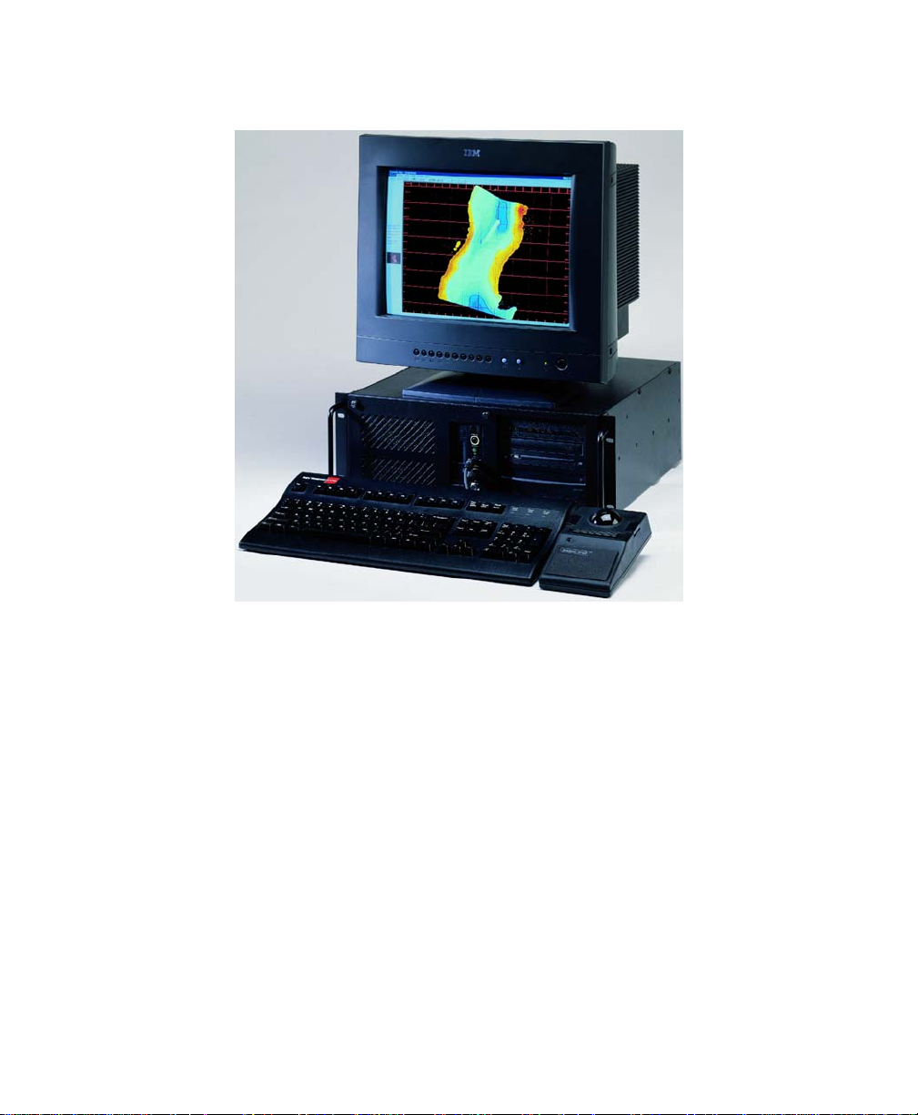
Figure 1-1. Isis system by Triton Elics
The Isis hardware and software system is modular. Isis modularity gives the user
the means to customize the data acquisition system for a specific task. The
modular nature of Isis system architecture also eases modification and
expansion of the system as needs change.
Users can develop server programs that operate outside of Isis. Again, Isis
modularity makes this possible. The server programs can communicate with Isis
through dynamic data exchange (DDE). Triton Elics provides the user with
variable names and DDE hooks to facilitate such conversations and even
provides an example server as a guide.
Chapter 1: Isis Overview
Page 17

June 2004 Isis® Sonar User's Manual, Volume 1 3
1.2 Theory of Isis Operation
The early data acquisition and image processing efforts at Triton focused on
side-scan sonar imagery. Significant advances were made in the acquisition and
processing of side-scan sonar data. These advances have drastically improved
the resolution of data acquired with Triton Elics’s systems and eased
interpretation of these data.
1.2.1 Background
Triton set out in 1984 to provide a color video display to image sonar data in
up to 256 colors, matching the 48 dB dynamic range of most side-scan
sonars. Triton’s first color display system was called SMIPS. Even though
SMIPS only produced 16 colors, the colors were much more easily
distinguished than shades of gray. When Triton introduced Q-MIPS in 1988,
Q-MIPS provided a full 256-color display and many user-selectable color
look-up tables (LUTs).
The power and flexibility of the color displays encouraged Triton to add
many image processing features to Q-MIPS similar to those used in other
image processing systems that focus on optical and radar imagery from
satellites. Q-MIPS was a full-functioned, data collection system employing
advanced tools for image analysis. Some of the features that have made
Q-MIPS unique as a data acquisition system are:
• oversampling with user control over downsampling methods
• preservation of dynamic range
• data fusion
• beam pattern and grazing angle compensation
• geocoding
• flexible mass storage
• hardcopy output
Q-MIPS also served as the basis for other advanced sonar imaging
products that have attacked the traditional distortions present in side-scan
images.
Chapter 1: Isis Overview
Page 18
June 2004 Isis® Sonar User's Manual, Volume 1 4
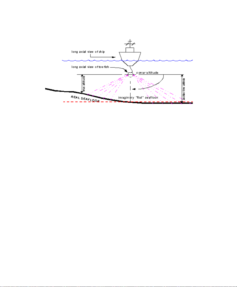
Figure 1-2. Imaginary seafloor as arbitrary reference point for sonar
altitude
Isis grew out of the Q-MIPS system and incorporates many new features;
for example it now has the ability to incorporate topographical information
from multibeam echo sounder data.
Isis now has the ability to use topographical data from multibeam echo
sounder data to correct the side-scan imagery. Isis provides a modular,
compact, low-cost alternative to Q-MIPS. As described in the following
paragraphs, Isis, following in the footsteps of Q-MIPS, offers many
improvements over previous data acquisition and imaging systems. Like
Q-MIPS, Isis actually improves the performance of the side-scan sonar and
provides a powerful interface that allows the user to manipulate and
interpret sonar imagery and subbottom data. Isis also takes full advantage
of the latest graphics cards and all of the on-board memory found there. As
a result, Isis richly displays its imagery in millions of colors.
1.2.2 Data Acquisition
A goal at Triton Elics has been to simplify the task of acquiring and storing
different data types. Along these lines, the Isis system has been designed to
acquire many of the types of data used in search and survey, both on land
and at sea.
Towfish telemetry data can be acquired by Isis via several different
interfaces. These data can be merged with the navigation and acquired via
Chapter 1: Isis Overview
Page 19

June 2004 Isis® Sonar User's Manual, Volume 1 5
the same serial port. Alternatively, another serial port can be used. Custom
interfaces can also be created by Triton Elics for sonars whose telemetry
data is transmitted in a specific manner.
1.2.3 Real-Time Data Processing
With real-time processing, it is possible for the user to interpret features
visible in the processed data (but perhaps not in the raw data) as they are
collected. This allows decisions to be made in real time based on these
interpretations.
In side-scan sonar data, Isis removes the water column, corrects the slantrange, and corrects the along-track speed — all in real time. These features
ensure accurate visualization of the seabed. With the advent of real-time
mosaicking, a true, georeferenced picture of the area can be generated as
the survey occurs.
Processing data in real time does not preclude saving the raw data. During
acquisition Isis always saves the raw, uncorrected data.
1.2.4 Combining Navigational and Acoustical Data
While Side Scan Sonar imagery and Multibeam Sonar data is acquired,
other forms of data can be entering Isis via the serial ports. For example, a
navigation device or an integrated navigation computer may be connected
to a serial port in the Isis system. Also, towfish telemetry (including pitch,
roll, heading and depth) are often interfaced and sometimes combined with
the navigation data. All of these data are merged into a standard XTF data
format in the host computer before being passed on to a mass storage
device.
Data fusion is an important aspect of the Isis design. The simultaneous
acquisition of navigation data and acoustic data allows for real-time
positioning of any pixel of imagery (geocoding). If the towfish is crabbing or
yawing while towfish telemetry is interfaced to Isis, these corrections will
also be included in geocoded positions. Navigation data entering Isis ca n be
used to determine the speed over ground. This information is employed to
correct the imagery in real time or in playback mode, allowing rectilinear
rendering (that is, equal scale in both the along-track and across-track
directions).
All of the data acquired can be used to generate a side scan sonar “map” or
“mosaic,” which can be imported into TEI’s GIS Delph Map package and
combined there with almost any other georeferenced data.
Chapter 1: Isis Overview
Page 20

June 2004 Isis® Sonar User's Manual, Volume 1 6
1.2.5 Choice of Data Storage Formats and Media
Isis is capable of storing data in one of three standard data formats: XTF,
Q-MIPS and SEG-Y. The XTF (Extended Triton Format) format, originally
developed by Triton for storage of data collected with Isis systems, has
gained such popularity that some organizations which do not even own an
Isis have adopted it because of the format’s flexibility and ease of use, and
also because so much data have been collected by others using Isis
systems.
At minimum, each Isis system provides a large hard disk drive and CD readwrite drive. Any additional storage media, such as Magneto Optical (MO)
drives, removable hard disk drives, Jaz drives, etc., can be supplied.
1.2.6 Hardcopy Records
Isis currently supports many hardcopy output devices — see ‘Hardcopy
Devices Supported by Isis’
Centronics standard are provided at no additional cost when a printer is
purchased from Triton Elics.
( 5.1). Other printer interfaces using the
Chapter 1: Isis Overview
Page 21

June 2004 Isis® Sonar User's Manual, Volume1 7
Chapter 2 Getting Started with Isis Software
Your system comes to you with your Isis software already installed on your hard
disk. This chapter explains:
• what software is provided with your system and where it is
located
• how to run Isis
• what the icons on the Isis main menu mean
• what the basic modes of operation are
• what basic keyboard shortcuts are available
• how the trackball is used with Isis software
• what special utilities are available to you to control your screen
display
2.1 Software Installation Notes
Typical software installation CD will contain folders like the ones depicted in the
Windows Explorer layout. (See the figure,
installation folders’
.)
‘Typical listing of TEI software
Chapter 2: Getting Started with Isis Software
Page 22

June 2004 Isis® Sonar User's Manual, Volume1 8
Figure 2-1. Typical listing of TEI software installation folders
TEI software is compatible with Windows 95, Windows 98, Windows NT 4.0, and
Windows 2000. The following notes will help you achieve a smooth installation of
the software.
• Please exit from all other applications before running any of the
installation programs.
• You will not be able to complete the installation on an NT4.0 or
Windows 2000 system if you do not have administrator’s rights.
All Isis “black boxes” ship with a user name Isis. In this case the
Isis user name has administrator’s rights and does not require a
password.
Chapter 2: Getting Started with Isis Software
Page 23

June 2004 Isis® Sonar User's Manual, Volume1 9
• Each application is installed by browsing to the appropriate folder
(for example, Isis5.50 Install) on the CD and double-clicking on
the SETUP.EXE file found in that folder.
• TEI recommends that if you have more than one hard drive, you
install the software on the second (usually the D:) drive, using
the default folder names on the CD. You will be given the option
to select any drive during the setup process, select the Custom
option and change the drive letter.
• The first installation on an NT4.0 system requires a re-boot
during the installation; however, this only occurs for the first
installation. Under Windows 2000, no rebooting is necessary
during the installation process. However, you must reboot the
system after installing under Windows NT 4.0.
• For each application, a number of sample data files can be
optionally installed. These files will reside in a subfolder called
Demo Files within each application’s main folder. These special
files can be played back or processed by the relevant TEI
applications without a TEI sentinel being installed. If no sentinel
(dongle) is attached, a message displays, indicating either that a
sentinel was not found or that the sentinel is damaged. However,
you can still play back the sample files that come from the CD.
• In order to run the software in acquisition mode, or to play back
or process other files, you will need a TEI sentinel attached to
the LPT1 printer port. Contact TEI if you need a sentinel.
• If the operating system is Windows NT 4.0 or Windows 2000,
you will need to install a sentinel driver. The driver is included on
the CD in the Sentinel folder; a text file, with installation
instructions, is in that folder.
• In the case of Windows NT 4.0, Service Pack 5 (or higher) needs
to be installed. Service Pack 5 is on the CD.
• The TEI manuals that are installed with the software are in
Adobe Acrobat PDF format. Acrobat Reader software (required
to read the PDF files) is also on the CD.
• The CD has a number of other folders containing drivers and
applications that could be required; each folder has a text file
with more information.
• To remove the software, use the Add/Remove Programs utility in
the Windows Control Panel collection of utilities.
Chapter 2: Getting Started with Isis Software
Page 24

June 2004 Isis® Sonar User's Manual, Volume1 10
• The installations make two changes which are not restored when
the programs are removed using Add/Remove Programs. They
are: the addition of a folder called [TEIdlls] in the Windows or
WINNT folder; and a modification to the PATH environment
variable, which adds the [TEIdlls] folder to the PATH. The
[TEIdlls] folder can be safely deleted after all TEI software has
been removed.
2.2 Upgrading to a Newer Software Version
If you already have a version of the software that you wish to upgrade on your
system, you will see a dialog box inviting you modify, repair, or remove the
software you intend to install. See the figure, ‘Modify, Repair, Remove choices
during installation’
for an example of this kind of dialog box.
Figure 2-2. Modify, Repair, Remove choices during installation
Chapter 2: Getting Started with Isis Software
Page 25

June 2004 Isis® Sonar User's Manual, Volume1 11
You will need to remove the old version of the software before you will be
permitted to install the new version. To do so, enable the
dialog box and click
setup.exe. As noted above, some items are deliberately not removed during the
uninstall process; doing so can cause problems. If necessary, manually delete
\TEIdlls folder, but only do this if you are going to re-install all TEI
the
applications.
Important Note: The Windows Installer will fail to uninstall the software if the
operating system has been upgraded from (for example) Windows 98 to
Windows 2000 after the TEI applications were installed. If you want to upgrade
your operating system, uninstall the TEI programs first, and then re-install the TEI
programs after the upgrade.
Next. You can then install the new version by rerunning
Remove button in the
2.3 Solutions to Some Common Problems
Problem: After about five minutes the installation does not complete and the
Windows desktop does not return.
Solution: Try again after using <CTRL>+<ALT>+<DEL> to shut the system
down and restart. The problem can be caused by applications
running in the background or not being shut down before running the
installation.
Problem: Under NT/98 the installation may fail after the first re-boot, with a
message that it cannot locate the file setup.exe.
Solution: This can occur if the CD ROM drive is slow getting started after the
first reboot. Just use Explorer to double-click on setup.exe again,
and the installation will proceed normally.
Problem: There is insufficient space on the C: drive, even though D: (or
another) drive has been chosen to install the programs.
Solution: Under Windows 95, 98 and NT, the Windows Installer needs to build
the complete Installer Engine and files on the C: drive. The file can
be as large as 250 MB for a full installation. Windows 2000 will
require much less space, since the operating system includes the
Installer Engine.
Problem: After the Installation completes, you see the message, “The dynamic
link library map.dll could not be found in the specified path” when the
program is started.
Chapter 2: Getting Started with Isis Software
Page 26

June 2004 Isis® Sonar User's Manual, Volume1 12
Solution: You MUST reboot the system after finishing the installation. This is
necessary so that changes to PATH environment variable can be
applied.
Problem: You may not be able to install all the options (demo files, manuals,
help files) unless you can free enough space on the C: drive.
Solution: Consider using the Minimum Installations option located on the CD
to install only the programs you need.
Problem: When first running Isis after installing a new version, you receive an
error message that says your Isis CFG configuration file is out of
date.
Solution: This message alerts you that CFG files created with versions of Isis
earlier than this version of Isis are incompatible. Click OK during
your current Isis session. In future Isis sessions, the incompatibility
message will no longer appear.
Problem: Your receive error messages such as ‘the procedure entry point
xxxxxxxxx could not be located in the dynamic link library yyyyyy.dll
when trying to start one of the TEI applications.
Solution: This error may occur on a system that has had earlier versions (prior
to Fall 2000) of TEI software installed. Use Windows Explorer to
search for the following files:
About.dll HydroNavCurve.dll mpx_map.dll ShpLib.dll
ASRVAPI.dll HydroNavInfos.dll Navpntw.dll SinglePrc.dll
Attitool.dll HydroNavPlan.dll Navprcw.dll SpeckleFilter.dll
AuxDlfDll.dll HydroTools.dll Navtools.dll Speed.dll
Bathtool.dll ImpObj.dll ObjectDll.dll TEISplash.dll
Chrutlw.dll Importxt.dll ObjectToBdd.dll TeiGUIExt.dll
CMGBase.dll LinearFeature.dll Palette.dll TEImpxmap.dll
D24Param.dll lxtools.dll patchtst.dll Tide.dll
DdsErr.dll TEImap.dll PIPETRK.DLL TimeTag.dll
dxflib.dll mifutil.dll PitchYaw.dll TVGAuto.dll
Encode.dll MOSAIC.DLL Printer.dll VecPropDll.dll
EncodeS.dll Mpx_Country.dll profile.dll Vif2xyz.dll
Geometry.dll Mpx_line.dll qtclib.dll Volume.dll
geotiff.dll Mpx_main.dll SeisDemo.dll XtfTools.dll
HydroNavAtti.dll mpx_map.dll Serialdll.dll
Chapter 2: Getting Started with Isis Software
Page 27

June 2004 Isis® Sonar User's Manual, Volume1 13
The files must be unique on the system (that is, there must be only
one instance throughout your entire computer). The installer copies
the latest version to a folder {Windows Folder}\TEIdlls during the
installation process. If any files with the above names are found that
are not in {Windows Folder}\TEIdlls, then you should delete (or
rename) them.
Problem: You receive an error message during installation of TEI software.
For example, you may see this message:
Error – Unable to write to temporary location
Solution: You may see that message if you are running certain anti-virus
software, such as Norton (or other brands too). Check to see that
you have disabled your anti-virus software. The solution is to
temporarily turn off Norton Auto-Protect:
1. Right-click the Norton icon (or other anti-virus icon) on the Windows
taskbar.
2. Select Disable Auto-Protect when prompted.
3. Resume installing your TEI software.
4. When the installation completes, re-boot your PC.
5. When the system restarts, Norton Auto-Protect will be re-enabled by
default.
2.4 Checking for Dongles and Licenses
If a dongle is not detected, the software looks for a software license. The system
first checks locally, then remotely, to find a license.
If a local, fixed license file is not found, the software checks the computer registry
to see if a license path exists for a floating license. If not, the software asks the
user to navigate to a license file stored on the network. The floating license can
be configured for one to many concurrent users. If a floating license file is used,
the system uses one license each time Isis runs; if a fixed license file is used,
many instances of Isis can run simultaneously, and there is no limit on the
number of allowed instances (same as with a dongle). Figure 2-3 shows the
initial dialog you get if you don’t have a working dongle installed on your
computer. If you don’t have a dongle, you must have a fixed or floating license. If
you have neither a dongle nor a license, Isis will run in demo mode only.
Chapter 2: Getting Started with Isis Software
Page 28

June 2004 Isis® Sonar User's Manual, Volume1 14
Figure 2-3. Find License File dialog box
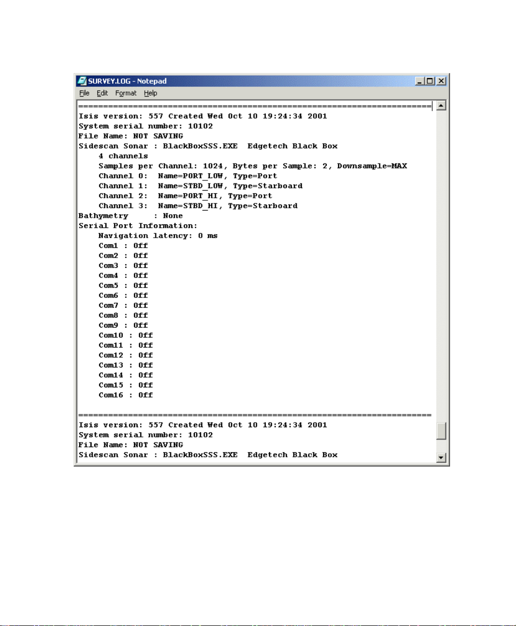
2.5 Keeping a Log
In Record Mode, Isis appends text entries to a file called SURVEY.LOG located
in whatever drive Isis is running from. When logging in Record mode begins, Isis
adds to the file:
• date and time
• version of Isis currently running
• system serial number
• file name
• name of the sonar
• number of sonar channels, number of samples per channel and
their configuration
• number of bathymetry channels and all related setup information
including installation offsets
• the template for each serial port
In summary, all settings that affect the way data is stored are noted in the
SURVEY.LOG file. Ordinarily, Isis appends to the file only when logging has
Chapter 2: Getting Started with Isis Software
Page 29

June 2004 Isis® Sonar User's Manual, Volume1 15
begun or the file name changes. However, when the Klein 5000 server is
running, all sonar settings that controls the Klein 5000 sonar are also noted in the
file. A sample of part of the contents of a
Figure 2-4.
Instead of modifying
It is potentially dangerous for you to open the survey.log file, modify it,
and save it back to disk while Isis is running — Isis may be modifying
the file at the same time you are trying to edit it or save it!
survey.log while Isis is running, consider these alternatives:
• If storing to an XTF file, click the NOTE: button in the Parameter
Display window. If you click the NOTE: the contents of the Notes
text are saved into the XTF file, are posted to the
file, and printed (if hardcopy is turned on).
• Use Notepad to open a different ASCII file. The file should be
named something other than
SURVEY.LOG file is shown in
SURVEY.LOG
D:\SURVEY.LOG.
Chapter 2: Getting Started with Isis Software
Page 30
June 2004 Isis® Sonar User's Manual, Volume1 16
Figure 2-4. Sample SURVEY.LOG created by Isis
If the first line of the log file contains only the characters LOG, Notepad will
automatically insert the current time and date each time the file is opened. You
also can press F5 to insert the current time and date at the insertion point. Refer
Chapter 2: Getting Started with Isis Software
Page 31

June 2004 Isis® Sonar User's Manual, Volume1 17
to your Windows documentation for detailed instructions on using the Notepad
editor.
2.6 Providing Runtime Parameters to Isis
Sometimes you might want to pass extra information to Isis when you start the
program. You can do so through the Windows graphical user interface or at the
DOS prompt. In both environments, Isis recognizes certain switches, explained
next, as the means for passing the information.
To create a Windows shortcut and add a switch to it:
1. Go to the directory that contains the Isis executable ISIS.EXE and create
a shortcut:
Use the right mouse button to drag ISIS.EXE to the Windows
Desktop.
From the pop-up menu, choose Create Shortcut(s) Here.
2. Right-click the shortcut and choose Properties (or choose File
→Properties →Shortcut from the Explorer menu).
3. In the text box called Target, type the executable name
<SPACEBAR>, type a forward slash and a switch name (no space after
the slash); then click
See Table 2-1 for the switches you can add to your shortcut.
OK.
ISIS.EXE, press
Chapter 2: Getting Started with Isis Software
Page 32

June 2004 Isis® Sonar User's Manual, Volume1 18
Table 2-1. Isis runtime switches
Switch Name What the Switch Does
/CFG={parm}
parameter {parm} to the right of the equal sign has
the form
If you don’t specify a CFG name, the system uses a
default
computer name. This allows the program to be run
from a single network directory to many different
workstations, each with its own configuration file.
For
configuration to use for this session. For example:
/CFG=ISIS2.CFG
In the example, the configuration gets saved into
ISIS2.CFG when you explicitly save it in Isis (from
the main menu:
you exit Isis (assuming you have told Isis to be
prompted for any configuration changes).
When you set up Isis this way, you can run different
sessions from the same directory by using
configuration files unique to your different Isis
sessions.
{filename}.CFG
CFG file name of ISIS_ plus the local
{file_name} substitute the name of the Isis
Configure→Save Setup), or when
Chapter 2: Getting Started with Isis Software
Page 33

June 2004 Isis® Sonar User's Manual, Volume1 19
/GOTOTIME={parm}
/GOTOTIMEALL={parm}
parameter {parm} to the right of the equal sign has
the form
dd/mm/yyyy_hh:mm:ss
and causes Isis to start playing at the given date
and time in the current file. Note: Any single
character (including spaces) can be used as a
delimiter to separate time and date values.
Example (for space reasons, shown on wrapped
lines here):
Isis c:\xtfdata\034_1325.xtf
/GOTOTIME=02/01/2001_13:35:05
In the example, Isis plays file 034_1325.xtf, starting
at Feb 1, 2001 at 13:35:05.
parameter {parm} to the right of the equal sign has
the form
dd/mm/yyyy_hh:mm:ss
and causes Isis to search for the given date/time in
the current directory. Note: Any single character
(including spaces) can be used as a delimiter to
separate time and date values.
Example (for space reasons, shown on wrapped
lines here):
Isis /GOTOTIMEALL=02/01/2001_13:35:05
In the example, Isis plays files until it reaches the
first file that has a playback time of Feb 1, 2001 at
13:35:05.
Chapter 2: Getting Started with Isis Software
Page 34

June 2004 Isis® Sonar User's Manual, Volume1 20
/GOTOPING=n
/HELP or /?
/NOWARN
/OPENGL
/PAUSETIME={parm}
The parameter n must be an integer representing
a ping number in the file to be played back. Isis
starts playing back the file at the given ping
number.
Example:
Isis c:\xtfdata\034_1325.xtf
/GOTOPING=1234
In the example, Isis plays back file 034_1325.xtf
starting at ping 1234.
displays all other recognized command-line
parameters
Warnings won't appear about the number of colors
on startup. Also, if you are running Isis in demo
mode (without a dongle being present), warnings
will not be displayed prior to running Isis. The
/NOWARN command-line parameter now also
suppresses active ASCII report warning.
With this switch, True-3D (Open GL) mode of
operation becomes available to you in Isis. This
feature also can be accessed from the
Window→Mulitbeam Bathymetry→True-3D
(Open GL)
menu choice. Caution: Open GL can be
very CPU-iintensive, depending on your graphics
card.
parameter {parm} to the right of the equal sign has
the form
hh:mm:ss
and causes Isis to automatically pause playback
when the given time is reached.
/RECORD
/RECORDSAVE
This puts Isis into display-only Record mode.
This puts Isis into Record mode and starts logging
to a file.
Chapter 2: Getting Started with Isis Software
Page 35

June 2004 Isis® Sonar User's Manual, Volume1 21
/SESSION=n
{filename}.XTF
{filename}.DAT
{filename}.SEG
{filename}.RUN
For optimum Isis performance, do not run more
than one Record mode session at a time.
Isis runs and identifies this particular session of the
Isis program with the number
digit integer you specify) in the program’s Title Bar.
For example, you could start one session of Isis
with the command line ISIS.EXE /SESSION=1
and another with the command line ISIS.EXE
/SESSION=2
insensitive. The Title Bar of each Isis session will
then indicate session 1 or 2. For example, suppose
you wanted to start Isis and play back the file
LINE1.XTF:
D:\>ISIS.EXE /SESSION=1 D:\LINE1.XTF
Later, you can direct that same Isis session to play
back a different file, say
following command:
D:\>ISIS.EXE /SESSION=2 D:\LINE2.XTF
Without the
Isis would be launched rather than using the
existing session.
Specifying a specific filename with any of these
three file extensions from a DOS box or from a
shortcut runs Isis and plays back the named file.
Example:
{filename}.RUN is an Isis batch file. (For batch file
methods, see
.)
Sets’
. The command string is case
/SESSION switch, a new instance of
ISIS LINE1.XTF. The type of file called
‘Playing Back a Series of Data
n (n being a single-
LINE2.XTF, via the
Chapter 2: Getting Started with Isis Software
Page 36

June 2004 Isis® Sonar User's Manual, Volume1
Chapter 3 Using the File Menu
You use the File menu to manage common tasks in Isis:
record or play back Isis imagery from a disk or tape drive
prepare Isis to record new data in a particular file format or medium
move rapidly — by time, ping, or location — to different parts of a data set
print some or all of a data
Plotter/Printer'
This chapter explains these functions found in the File menu.
To access the File menu
1. Load Isis from Windows by double-clicking the Isis icon.
2. Choose
The system displays the File menu functions. An example is shown in
Figure 3-1.
).
File from the list of available menus.
set (§5.6, ‘Sending Isis Imagery to a
22
Chapter 3: Using the File Menu
Page 37

June 2004 Isis® Sonar User's Manual, Volume1
23
Figure 3-1. The File menu from the main menu
If a choice is grayed out, that choice currently is not available to you until you
take some other action.
3.1 Playback
You use this function to open a data set from disk or tape and play it back for
viewing and/or post-processing. Valid data set file types are
TRA, and RUN. The RUN file type refers to an Isis batch file (described in this
section).
Chapter 3: Using the File Menu
DAT, XTF, SEG,
Page 38

June 2004 Isis® Sonar User's Manual, Volume1
Note that if you are playing back a file and you save the configuration when
exiting, the next time you open Isis from the desktop icon, the last file played
back will begin playing automatically.
24
3.1.1 Playing Back data Sets from Disk or Tape
Data sets can be played back from disk or tape.
To play back a data set from tape
Please refer to §3.2, ‘Working with SCSI Tape’. Also refer to ‘Playing Back
from Tape’.
To play back a data set from disk at the time you run Isis
Either:
From the DOS command prompt type
.SEG | .TRA]
Drag and drop a valid file name onto the Isis icon.
With either of the above methods, the result is that Isis runs and then you
can see your file’s imagery start scrolling on your screen.
To play back a data set from disk after running Isis
Either:
Click the Play icon, specify a valid file in the available test box, and click Open, or
from the DOS command prompt type ISIS, a space, {filename [.XTF | .DAT |
.SEG | .TRA]}, and press <ENTER>, or
Drag and drop a valid file name onto the Isis open workspace window, or
From the main menu choose File→Playback, click Read from Disk, specify a
valid file in the available test box, and click Open
With any of the above methods, your file’s imagery then starts scrolling on
your screen. Also see ‘
To slow down or speed up your playback
Either:
Click the alking man icon to slow down the playback,
}, and press <ENTER> or
Playing Back a Series of Data Sets,’ below.
ISIS, a space, {filename [.XTF | .DAT |
or
Chapter 3: Using the File Menu
Page 39
June 2004 Isis® Sonar User's Manual, Volume1
Click the running man icon to speed up the playback
Each click decreases or increases, respectively, the rate of playback by one
ping to read per update.
From the main menu choose
options to control playback speeds.
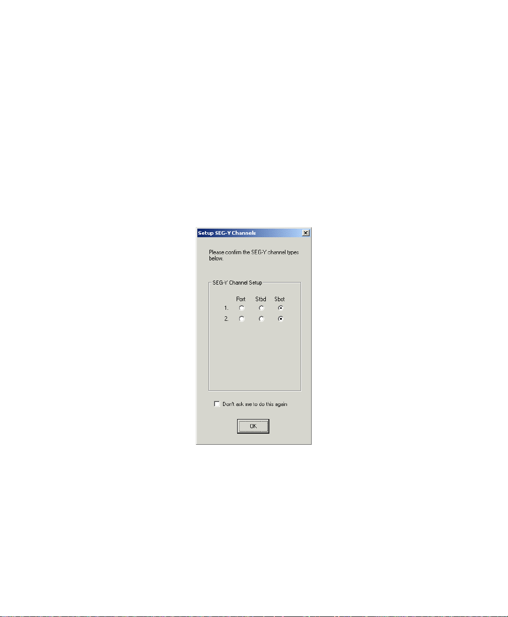
To play back a SEG-Y data set
Because Isis needs to know which channels use which data when playing back a
SEG-Y data set, Isis displays the dialog box shown in Figure 3-2 when you
specify a SEGY file to play back. Simply match your data to the appropriate
channels and click OK.
Configuration→Playback Speed for more
25
Figure 3-2. Set-up SEG-Y Channels dialog box
3.1.2 Playing Back Files from End to Start (aka
Backwards)
As of Isis version 4.78, you can play back Isis data sets from the end of the
file to its start — backwards from the way it was recorded, from the bottom
Chapter 3: Using the File Menu
Page 40

June 2004 Isis® Sonar User's Manual, Volume1
of the file to the top of the file. This can be done with any XTF, TRA, DAT or
SEG-Y file.
The advantage of playing a file backwards occurs when you want to visually
compare similar data running side-by-side. This is possible only if you are
playing back at least two files in separate Isis sessions (one file per Isis
session).
For example, let’s say a survey line was conducted north to south to record
some side-scan data. Then another survey line was conducted south to
north over the same area. In playback mode, you now can visually compare
the lines by opening two sessions of Isis and simultaneously playing back
the two files — one line playing back in the conventional forward direction,
the other line playing back in reverse. From the perspective of your
computer monitor, both lines will be scrolling down (from top of screen to
bottom of screen), making it possible for you to glance back and forth from
the two sets of images and perhaps spot differences in the lines as the
images scroll.
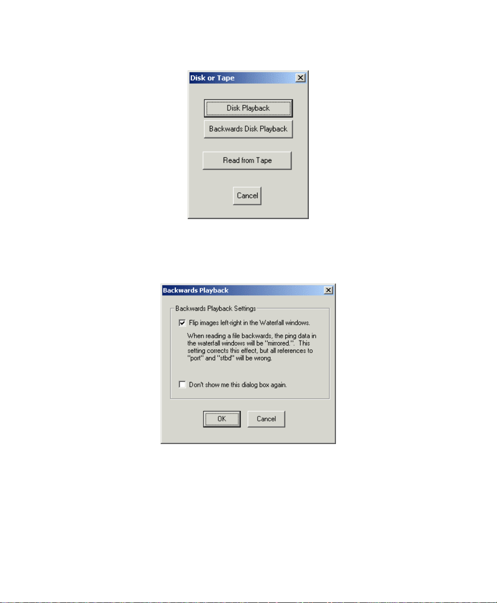
To play back a file so that it runs backwards (end to start)
1. Run Isis without specifying a file at the same time that you run the
software.
2. From the main menu, choose
File→Playback.
Note: The Play icon on the taskbar is reserved for playing back files in
the forward direction. You cannot use the
Play icon to play a file
backwards.
The system displays the Disk or Tape playback dialog box (Figure 3-3).
26
Chapter 3: Using the File Menu
Page 41
June 2004 Isis® Sonar User's Manual, Volume1
Figure 3-3. Disk or Tape playback dialog box.
3. Click Backwards Disk Playback.
The system displays the Backwards Playback dialog box (Figure 3-4).
27
Figure 3-4. Backwards Playback dialog box
As the Backwards Playback dialog box shows, you can flip the waterfall
image left-right to compensate for the lateral inversion caused by the
backwards playback. If you do, however, be aware that your references
to port and starboard will be similarly flipped.
Chapter 3: Using the File Menu
Page 42

June 2004 Isis® Sonar User's Manual, Volume1
g
y
playing
28
4. Click
5. Choose a file to play backwards and click
OK or Cancel.
If you click
(Figure 3-3). If you click
can choose or browse for the file to be played backwards.
The file plays back from its end of file toward its beginning of file. While
this happens,
Parameter Display window. Also, the clock and ping numbers run
backwards. However, the scrolling direction is still top to bottom on the
computer monitor.
When the start of the file is reached,
Parameter Display window (instead of
a file that completed its playback in the normal forward direction).
Port and starboard channels are not reversed. So, if you
are mosaickin
finished mosaic is a record which is flipped left and
right —
create a snip file while a file is being played backwards,
you might end up with a XTF or DAT file which is flipped
upside down. That, too, might be an effect you didn’t
want. Consequently, you’ll need to anticipate the
outcome when you are working with files that are
Cancel, Isis returns to the Disk or Tape dialog box
OK, Isis displays an Open dialog box where you
Open.
Backward Playback displays near the file name in the
AT START displays in the
AT END, as would be the case for
a file that is being played backwards, the
ou may or may not want this effect. Also, if you
back in reverse.
As with playing back a file the normal way (from beginning to end), you can
pause the scrolling file by pressing <SPACEBAR>. You can also use the
PageUp] and [PageDown] keys to skip forward or backward 500 pings at a
[
time in the scrolling file, as you can do for a file being played back in the
conventional start-to-end mode.
To start the file playing backwards over again
Either:
Press
[End], or
Chapter 3: Using the File Menu
Page 43

June 2004 Isis® Sonar User's Manual, Volume1
-
29
Choose
File→Goto→End
The playback starts over again from the end of the file to the start.
3.1.3 Playing Back a Series of Data Sets
Starting with Isis version 4.52, Isis has limited support for playing back files
in batches, or sets. An Isis batch file is identified with the file type extension
RUN and contains a list of file types Isis can recognize. When Isis opens a
RUN file, all files in the set play back, one after the other, until all files in the
set have been played or until you have pressed [
playing back of these files.
The principal reason for using Isis batch processi ng is related to mosaicking.
Batch processing in Isis gives you control over the order of files that you intend
to play back when you make a mosaic, rather than relying only on the order in
which you recorded your data during your survey operation. Specifying the
order can be important if you anticipate that some of your imagery in earlierrecorded
later
You can also daisy-chain
at the end of one
current
reference to a
RUN file when it is encountered by Isis in the listing. However, you cannot
nest
another
another
file, they will not be played back. For this reason, any reference in a
file to another
RUN file contains the reference to the second RUN file.
For example, consider the contents of this
If you played back this file in Isis, after Isis finished playing back
Furgbump.XTF and wallsnip.XTF, program control would transfer to
rundat.RUN. Furthermore, if the name of this RUN file was the same as the
batch file that began this playing back these files (in this case,
lines may be masked or occluded by overlapping imagery occurring in
recorded lines.
RUN files. Simply specify another RUN file name
RUN file to reference the next. You can even specify the
RUN name to loop a series of files. That is, if a RUN file contains a
RUN file, program control will be transferred to the named
RUN files (control cannot return implicitly to a RUN file that contains
RUN file). This means that if a RUN file contains a reference to
RUN file, and there are directory entries beneath the named RUN
RUN file should always be placed at the end of whatever
Furgbump.XTF
wallsnip.XTF
rundat.RUN
End] to terminate the
RUN
RUN file:
rundat.RUN),
Chapter 3: Using the File Menu
Page 44

June 2004 Isis® Sonar User's Manual, Volume1
the batch file would repeat itself and continue to loop like this until the user
took some action to interrupt the playback, such as pressing the
[End] key,
perhaps.
Finally, consider the contents of this RUN file called flawed.RUN:
Furgbump.XTF
wallsnip.XTF
rundat.RUN
runxtf.RUN
In the above example, playback of
runxtf.RUN would never occur from
flawed.RUN because when Isis reaches rundat.RUN, program control
would transfer to
rundat.RUN and not return to flawed.RUN when
rundat.RUN completes. (However, if the last line in rundat.RUN was
runxtf.RUN, then runxtf.RUN would be played back from rundat.RUN.) As
this example shows, Isis batch files can be daisy-chained but not nested.
To create an Isis batch file based on files in one directory
• At the DOS command prompt type
DIR *.{ext} /b > {filename} .RUN <SPACEBAR>
where
redirection symbol, and
(The
{ext} is a valid file type extension recognizable by Isis, > is a
{filename} is a valid Windows file name.
/b switch is for a bare listing so that you will get just the file
names — without size, date, or time.) For example,
DIR *.XTF /b > myXTFfiles.RUN <SPACEBAR>
In the above example,
all the
XTF files in the directory where you executed the DIR
myXTFfiles.RUN would contain a listing of
command to redirect output to a file. Of course, you can also specify
DAT, SEG, TRA or any combination of files that Isis can read and
play back. Figure 3-5 shows an example of a
RUN file created at the
DOS prompt.
30
Chapter 3: Using the File Menu
Page 45

June 2004 Isis® Sonar User's Manual, Volume1
Figure 3-5. Creating a RUN file from the DOS Prompt
While still at the DOS prompt, you can visually inspect the result by issuing
the DOS
TYPE command (Figure 3-6):
31
Figure 3-6. Inspecting contents of a RUN file from the DOS prompt
Chapter 3: Using the File Menu
Page 46

June 2004 Isis® Sonar User's Manual, Volume1
32
You can, of course, use a text editor to inspect or modify a
changing the order of the listed files or deleting or adding an entry.
To play back a batch file in Isis
• Open a
See ‘Playing Back Data Sets from Disk or Tape’.
RUN file just as you would any other file for Isis playback.
RUN file, such as
3.2 Working with SCSI Tape
Isis supports real-time data storage and playback to and from any sequential
SCSI device. A typical example is an Exabyte tape drive, but there is no check in
Isis software for any particular brand or model. Isis simply sends sequential
device instructions over the SCSI bus. As long as a tape drive complies with
SCSI-1 or later specifications, there should be no compatibility problems.
While recording or playing back to tape, Isis uses a portion of your hard disk to
temporarily store data. You should have at least 200 megabytes of free disk
space available in order to log to tape with Isis.
3.2.1 Block Size on Tape
Isis does not specifically set the drive’s block size. Typically, the block size
of a tape drive defaults to 1024 bytes. All read and write requests to and
from the tape drive are done in blocks of 1024 bytes. This is done to
maximize the drive’s data rate.
Note that any SEG-Y files recorded by Isis versions prior to v2.21 can be
read only by previous versions of Isis. This is because previous Isis versions
enforced the SEG-Y specification of varying the block size within a SEG-Y
file. Isis version 2.21 and later write data on the tape in a stream of 1024byte blocks exactly as it is read from disk.
3.2.2 Filemarks
Filemarks are written to the tape whenever:
• Recording was interrupted (Stop was pressed).
• A tape has been written to and is about to be rewound or ejected.
• The file name changed during recording.
Chapter 3: Using the File Menu
Page 47

June 2004 Isis® Sonar User's Manual, Volume1
Recording can resume by positioning the tape past a filemark before starting
Record mode or before copying a file from disk to tape. At that point, data
can be appended to the tape.
3.2.3 Features
While recording to a tape drive, you can zoom (log contacts) exactly as
though you were storing to hard disk. Also, one or two tape drives can be
used in a “round robin” fashion such that no data is lost when switching
tapes. With this technique, data logging can theoretically continue
indefinitely as long as the operator continues to insert fresh tapes into the
tape drive. A tape that is partially full can also have data appended to it.
3.2.4 Setting Up Tape to Record or Playback
The tape drive control software copies the current file to the tape drive as
the file is being written to by Isis. When recording or playing back, the tape
drive control software treats the hard disk file as a “temporary” file and
deletes it after the data are safely stored on tape. (You can override this
delete option.) Thus, the system hard disk is used as a cache for the tape
data.
Tape set-up in Isis is a one-time task. Once you set it, you shouldn’t have to
do to it again until you want to change a value set there.
Do not leave a tape in your drive while shutting down
your system. If you leave a tape in the drive during a
system shutdown, the next time you use Isis to
operate your tape drive your system might not be able
to find your “end of file” mark on the tape, where new
recording can begin. If there is a tape in your tape
drive, please eject it before you power down your
computer!
Never transport or move an Isis computer system with
a tape in an Exabyte tape drive! You run the risk of
severely damaging the drive!
33
Chapter 3: Using the File Menu
Page 48

June 2004 Isis® Sonar User's Manual, Volume1
To set up your tape for recording or playing back
1. From the Isis main menu, choose
File→Tape Drive Control→Options.
Isis displays the Tape Drive Control Options dialog box (Figure 3-9). This
dialog box shows that all temporary files created during playback and
recording sessions will be deleted after a playback or recording session
completes. This default choice saves you disk space. You can uncheck
the choice to delete temporary files if you believe you may want to refer
back to the temporary files later.
You can delete the tape-generated temporary files from the hard disk
once they’re copied to tape in record mode after your playback session.
If you wish to keep files in both places (disk and tape), then uncheck this
box. Note that if the temporary files aren’t deleted, the disk may
eventually fill up. If this happens, logging must stop. The Isis default is to
delete temporary files from disk.
2. You may want to:
• Specify a directory name to hold the temporary files created
during playback.
If it doesn’t matter to you where Isis puts the temporary files, you
can also accept the default directory, which is the root of the
current drive where you started Isis.
• Check the box to enable data recording to automatically start on
the selected tape drive when you start your recording session.
Initially, Isis shows this choice not selected.
If Isis detected one or more correctly configured tape drives (with
or without a tape inserted in the drive), your dialog box will
display “Tape Drive Online” in the tape drive status message
area of the Tape Drive Control dialog box. See Figure 3-7 for
typical contents of the Tape Drive Control dialog box.
3. Click
OK to close the Tape Drive Control Options dialog box.
Isis returns you to the Tape Drive Control dialog box.
4. In the Control portion of the Tape Drive Control dialog box:
34
Chapter 3: Using the File Menu
Page 49

June 2004 Isis® Sonar User's Manual, Volume1
• Click the tape drive radio button corresponding to the tape drive you
will be using. For a single tape drive, choose
tape drives in your Isis system, choose
(for the lower drive).
• Click either
method you want Isis to use when you want the recording or
playback to continue on the other tape drive.
You are now ready to record to tape or playback from tape in Isis.
Automatically (<5%) or Manually to set the switching
3. If you have a dual
3 (for the upper drive) or 4
3.2.5 Recording to Tape
You have two ways to record to tape: without or with immediate logging.
To record a file to tape without immediate logging
1. Click the
Recording begins.
2. When you are ready to start logging, click the
Parameter window.
Clicking
specify the maximum size a file shall have before a file switch will occur.
The default is 200 MB. When a file reaches 200 MB, Isis closes it,
creates a new name, and resumes saving to the new file. If saving to
tape, the tape drive control software will automatically delete the
previous disk file (unless you override it) and continue saving the new file
with no break on the tape data stream. In this way, the hard disk
behaves like a 200MB cache for the tape data. The data on the tape is
essentially one huge file, with filemarks written only if you press
if you rewind the tape for any reason.
To record a file to tape with immediate logging
1. You can also have Isis log your data to hard disk the moment recording
begins. For this method, first you start the data logging process, then you
start the tape drive:
2. Insert your SCSI tape into the tape drive you specified in the Tape Drive
Control dialog box.
Record button in the Isis main menu.
Switch button in the
Switch displays the Switch File dialog box where you can
35
Stop, or
Chapter 3: Using the File Menu
Page 50

June 2004 Isis® Sonar User's Manual, Volume1
36
3. From the Isis main menu choose
Data→Save As;
click
OK. You can pick any file name you want or let Isis default to the
JJJ-HHMM.XXX naming scheme.
Recording starts and Isis displays the specified file name in the
Parameter Display dialog box, along with other statistics for this session:
date, time, ping number, and remaining disk space.
From the Tape Drive Control dialog box (
choose
Note: If a device fills during recording, Isis writes to a file called
Record.
overflow.dat (or overflow.xtf) on the D drive; Isis then keeps
looking for available space to put the file.
supply a file name for the imagery to be captured and
File→Start Recording→Record
File→Tape Drive Control)
3.2.6 Playing Back from Tape
When playing back from tape, the following is performed:
1. The original file name (used when the data was recorded) is read from
the file header on the tape.
2. A file is created with the same name.
3. A file copy is begun, copying the file from tape to disk.
4. Then Isis starts playing that file back as it is being copied.
There are no “temporary files” any more during playback from tape. All files
are left on the hard disk and it is up to the user to delete them.
When a filemark is reached on the tape (signaling end-of-file), you again can
press the
playing the next file.
To play back a file from tape
1. Insert your SCSI tape into the tape drive you specified in the Tape Drive
2. From the Isis main menu choose
Play button in the Tape Drive Control dialog box to continue
Control dialog box.
File→Playback→Read from Tape
The system displays the Tape Drive Control dialog box (Figure 3-7).
Chapter 3: Using the File Menu
Page 51

June 2004 Isis® Sonar User's Manual, Volume1
37
3. Choose a playback option:
Start, Rewind 1 File
4. If you wish to play back the last file on the tape, choose Advance to End
then Rewind 1 File. Table 3-1 explains the options.
Reset Drive (Load Tape), Play, Rewind to
, or Advance 1 File.
Figure 3-7. Tape Drive Control dialog box
5. Choose Play to begin Playback
Isis reads the tape, displays the imagery on your screen, and reports
Reading from tape [#] (i.e., tape drive 3 or 4) in the Status portion of the
Tape Drive Control dialog box. While this is happening, Isis spools the
Chapter 3: Using the File Menu
Page 52

June 2004 Isis® Sonar User's Manual, Volume1
entire contents of the tape file to the temporary directory specified in the
Options portion of the Tape Drive Control dialog box (Figure 3-9). The
Parameter Display dialog box of Isis displays the usual statistics for the
active data imagery.
Table 3-1. Choices in Tape Drive Control dialog box
Option Meaning and Comments
38
Tape drive
Switch
between
drives
Reset Drive
Options
Play
Record
The 3 radio button refers to SCSI ID 3, and 4 refers to SCSI
ID 4. If you have a single tape drive in your Isis system, the tape
drive will be ID 3. If there are two tape drives in an Isis system,
the upper drive will be ID 3 and the lower drive will be ID 4.
You have two mutually exclusive choices:
• Automatically (<5%): If this radio button is darkened,
Isis will switch to the other drive when the current target
drive is 95% full.
• Manually: You force Isis to make the switch when you
click the Now! button. The switch occurs regardless how
full the current destination drive is.
In addition to rewinding the tape to its physical beginning, Reset
Drive retensions the tape, checks for available free space, and
prepares it for reading or writing at the compression ratio
specified via the tape’s utilities.
Displays the Tape Drive Control Options dialog box for
specifying the enabling or disabling of temporary files. You also
use this dialog box to perform tape copying operations. See
Figure 3-9.
Begins playing back a file from the current position of the tape.
The data imagery is spooled to your hard disk.
Records to tape from the current position of the tape. The tape
must be positioned at the start of the tape or at a filemark;
otherwise, a write error will occur.
Rewind
Positions the tape at its physical beginning.
to Start
Chapter 3: Using the File Menu
Page 53

June 2004 Isis® Sonar User's Manual, Volume1
39
Advance
to End
Rewind 1 File
Advance 1 File
Status
Positions the tape at the end of the last recorded file (at the
tape’s end of file mark). This action prepares the tape to have
data appended to the end of a previously recorded tape.
Positions the tape back one file from the tape’s current position.
Positions the tape forward one file from its current position.
Displays messages indicating which function is occurring now.
For the boxes designated Drive 3 and Drive 4, Isis shows the
function’s percentage of completion.
3.2.7 Continuing to Save Data to Another Tape
Isis can redirect recording to another tape in the middle of a session. This is
useful if you are running low on available tape and want Isis to continue
saving data on the second tape.
To switch to a different tape drive mid-session
1. Insert a tape into each tape drive.
2. From the Control portion of the Tape Drive Control dialog box
(File→Tape Drive Control), click on a radio button to indicate which
tape will be the first tape (3 or 4) to use in your recording session.
3. In the Switch between drives portion of the Tape Drive Control dialog
box, click on a radio button to indicate whether the switch will occur
automatically or manually.
4. Start recording.
If you choose Automatically (<5%), Isis will redirect your recording to
the second drive when you have less than 5% tape space remaining on
the first tape. If you choose Manually, Isis only redirects the recording to
the second tape when you click Now! in the Switch between drives
portion of the Tape Drive Control dialog box. You can also achieve the
same thing through the Switch File dialog box (Figure 3-8), which is
available to you when the Parameter Display window is displayed
Chapter 3: Using the File Menu
Page 54

June 2004 Isis® Sonar User's Manual, Volume1
Figure 3-8. Switch File dialog box (from Parameter Display window)
3.2.8 Copying Files to and from Disk and Tape
You perform these functions using the Tape Drive Control Options dialog
box (Figure 3-9) and its parent dialog box, the Tape Drive Control dialog box
(Figure 3-7).
40
Chapter 3: Using the File Menu
Page 55
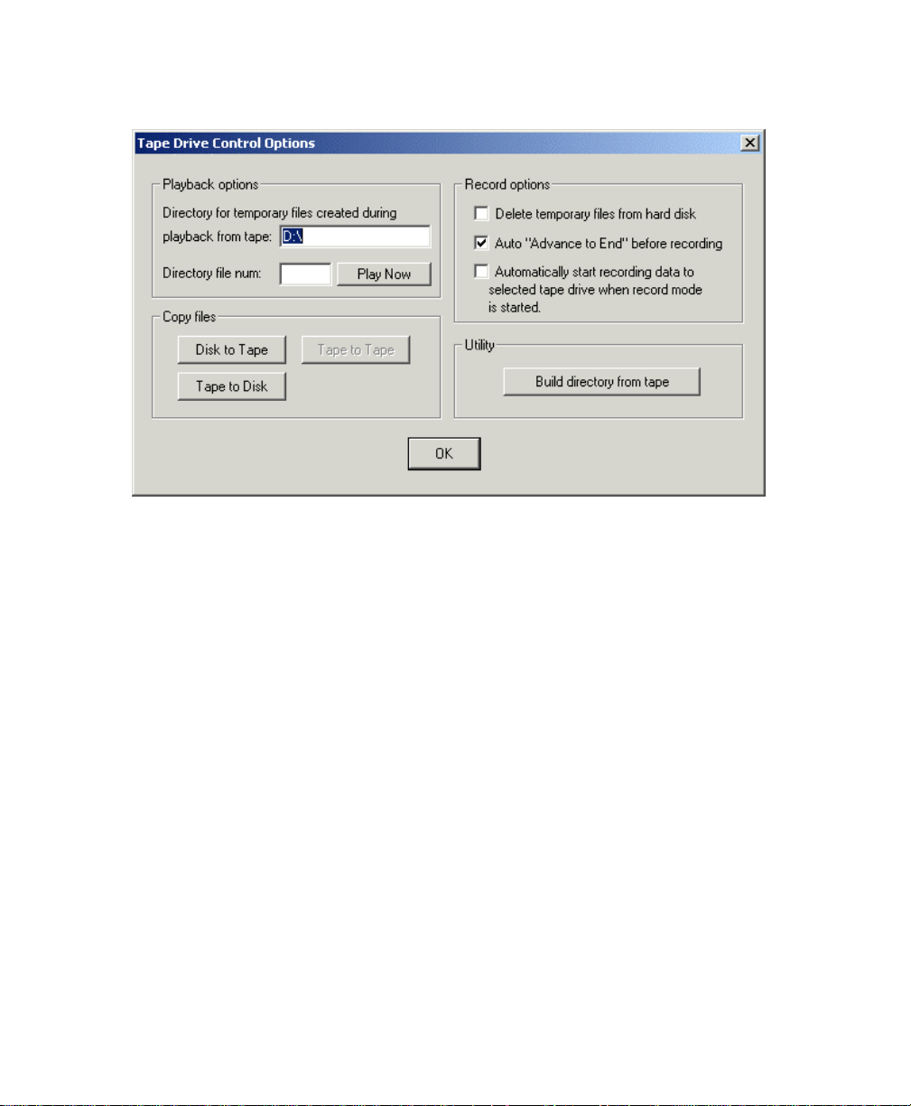
June 2004 Isis® Sonar User's Manual, Volume1
Figure 3-9. Tape Drive Control Options dialog box
To copy files from disk to tape
1. From the Isis main menu choose File→Tape Drive Control→Options.
2. In the Copy Files area of the Tape Drive Control Options dialog box, click
Disk to Tape, then click OK.
3. The system displays a dialog box where you can browse for a file name.
4. Choose a file name or multiple files by holding down CTRL and selecting
your files; then click OK.
Copying starts.
To copy files from tape to disk
1. From the Isis main menu choose File→Tape Drive Control.
2. When “Ready” displays in the drive status message area, click Rewind
to Start or Rewind 1 File.
3. Click Options to have Isis display the Tape Drive Control Options dialog
box (Figure 3-9).
41
F
Chapter 3: Using the File Menu
Page 56

June 2004 Isis® Sonar User's Manual, Volume1
4. In the Copy Files area of the Tape Drive Control Options dialog box, click
Tape to Disk, then click OK.
Copying starts.
To copy files from tape to tape
1. From the Isis main menu choose File→Tape Drive Control→Options.
2. In the Copy Files area of the Tape Drive Control Options dialog box, click
Tape to Tape, then click OK.
Copying starts.
3.2.9 Working the Tape Drive Control Options
Isis provides several options to help you automate your tape operations.
Automating your tape operations will help prevent any unwanted “data
recording lags” from occurring at record time. In addition, because these
controls are embedded in the Isis software, you can now run all aspects of
your tape operation from within Isis.
Table 3-2. Choices in Tape Drive Control Options dialog box
42
Option Meaning and Comments
Chapter 3: Using the File Menu
Page 57

June 2004 Isis® Sonar User's Manual, Volume1
43
Playback options
(two text boxes
and one button)
Record options
(check boxes)
Copy files
(child buttons)
Directory for temporary files created during
playback from tape:
In this text box you can specify a particular directory to
be the “working directory” to hold the files spooled to
disk while tape operations are underway. If you don’t
specify a temporary directory, ISIS will use your current
directory to hold the temporary files.
Directory file num
In this text box you can supply a number corresponding
to the name of a file you wish to play back.
Play Now
Starts playing the file number specified in Directory file
num. To get to the file, your system rewinds or
advances the tape from the current position on the tape,
bypassing (without playing back) any intervening files.
Delete temporary files from hard disk.
After a recording session has completed, you may want
to get rid of the temporary files, which can be rather
large. Use this option to have Isis automatically purge
them from your disk at the end of your session. The
default is to have this feature disabled (unchecked and
therefore off).
Auto “Advance to End” before recording.
You can further streamline your recording session by
having Isis automatically position the tape head to the
first point on your tape that has not been written to. You
can, of course, manually advance the tape to the first
unwritten portion by choosing File Tape Drive Control
and then clicking Advance to End.
Automatically start recording data to selected tape
drive when record mode is started.
Checking this option will begin recording your data to
the tape drive indicated by the darkened Tape drive
radio button in the Tape Drive Control dialog box (the
parent dialog box of Tape Drive Control Options).
Disk to Tape: See ‘To copy files from disk to tape’.
Tape to Disk: See ‘To copy files from tape to disk’.
Tape to Tape: See ‘To copy files from tape to tape’.
Chapter 3: Using the File Menu
Page 58
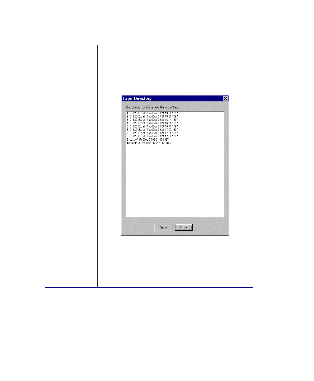
June 2004 Isis® Sonar User's Manual, Volume1
44
Utility
(child button)
Build directory from tape
Clicking this button directs Isis to display a sequential
list of file names with their creation dates and times.
You can use a file’s sequence number from this list as
the directory file num to play back. A sample listing, with
sequence numbers appearing in the leftmost column is
shown in Figure 3-10.
Figure 3-10: Tape Directory listing
Save Puts a copy of the tape directory listing in the
Windows NotePad editor, where you can save it as a
text file.
Close Closes the Tape Directory display box.
3.2.10 Related Settings for Tape Operations
Within Isis, you can get to some tape drive storage setting from parts of Isis
other than from File→Tape Drive Control.
Chapter 3: Using the File Menu
Page 59

June 2004 Isis® Sonar User's Manual, Volume1
3.2.10.1 File: Record Setup: File Format: Log to tape
When you choose Log to tape, the Tape Drive Control dialog box
automatically starts when Record Mode starts. It is there for convenience
only — the exact same thing can be accomplished by selecting Tape Drive
Control... from the File menu.
3.2.10.2 File: Record Setup: File Format: Log to tape:
Options…
This button activates the Tape Drive options dialog box. This is the same as
pressing the Options... button in the Tape Drive Control dialog box.
3.2.10.3 Switch: Switch to next file name when file…
The Switch button is located in the Parameter window. Clicking Switch
displays the Switch File dialog box where you can specify the maximum size
a file shall have before a file switch will occur. The default is 200 MB. When
a file reaches 200 MB, Isis closes it, creates a new name, and resumes
saving to the new file.
When file names end in a number, and Switch is performed, the number is
automatically incremented for a new file name and saving continues in the
new file. This does not apply to files named in the JJJ-HHMMSS format.
When using that format, the time and date are always used to create the file
name.
If saving to tape, the tape drive control software will automatically delete the
previous disk file (unless you override this choice) and continue saving the
new file with no break on the tape data stream. In this way, the hard disk
behaves like a 200MB cache for the tape data. The data on the tape is
essentially one huge file, with filemarks written only if you press Stop, or if
you rewind the tape for any reason.
45
3.3 Stop
The Stop option stops the current session whether it is running in Playback or
Record mode. Any file that may have been playing back when you clicked Stop
is no longer available until you explicitly re-open it. All windows, however, remain
open with their display parameters intact. If you choose Stop, you can open
another file by choosing Playback or you can start saving data by choosing Start
Recording.
Chapter 3: Using the File Menu
Page 60

June 2004 Isis® Sonar User's Manual, Volume1
3.4 Pause
The Pause option temporarily stops playback of data at the current ping.
Selecting Pause a second time resumes playback of data at the ping where
playback was stopped. The SPACEBAR is the keyboard shortcut for this
operation and toggles Pause on and off.
3.5 Scroll Direction
You can control the direction of a scrolling horizontal or vertical waterfall by a
menu selection or by keyboard keys.
To scroll imagery in the DOWN direction
• From the main menu either choose Scroll Direction→Normal (scroll
down), or press the down arrow (↓) on the keyboard.
The imagery scrolls from the current position in the file to later positions
in the file (moving toward the end of the scrolling file).
To scroll imagery in the UP direction
• From the main menu either choose Scroll Direction→Reverse (scroll up),
or press the up arrow (↑) on the keyboard.
The imagery scrolls from the current position in the file to earlier
positions in the file (moving toward the beginning of the scrolling file).
46
3.6 Isis Explorer
Isis Explorer (File→Isis Explorer) is a tool that allows the user to search for files
with the XTF extension and then list those files in various ways. The files can be
sorted by File Name, Start Time, End Time, Sensor Type, Range Scale (Rng),
File Size, Number of Pings; and Average Heading (CMG , or Course Made
Good). the files can also be listed in ascending or descending order. Figure 3-11
shows a window of files displayed by Isis Explorer.
Chapter 3: Using the File Menu
Page 61

June 2004 Isis® Sonar User's Manual, Volume1
47
Figure 3-11. Isis Explorer with sample XTF files listed
After the files are listed, the user can display one or more files in Isis by
highlighting a file or files and then clicking the toolbar Play button.
Alternatively, the user can drag the selected file and drop it into the Isis
workspace. While Isis displays (plays back) the data, the user can pause the
display from within Isis.
3.6.1 Isis Explorer Menus
Isis Explorer has its own menu of functions: File, View, Notify, and Help.
3.6.1.1 Isis Explorer File Menu
• File→Refresh: Refreshes the file listbox. The keyboard shortcut is F5.
• File→Specify Search Wildcard: Permits standard wildcard symbols ‘*’
(asterisk) and ‘?’ (question mark) to be used as part of the file name in
Chapter 3: Using the File Menu
Page 62

June 2004 Isis® Sonar User's Manual, Volume1
searching for one or more XTF files. This is the same dialog box
available from the main menu of Isis as File→Go To→Specify Search
Wildcard
File→Exit: Closes the Isis Explorer dialog box. The keyboard shortcut is
•
CTRL+X.
3.6.1.2 Isis Explorer View Menu
• View→Toolbar: Enables or disables the display of the toolbar. A
check mark next to Toolbar indicates the Toolbar display is enabled.
• View→Status Bar: Enables or disables the display of the Status
Bar. A check mark next to Toolbar indicates the Toolbar display is
enabled.
• View→Subdirectories: Shows subdirectories to perform searches
for files stored in subdirectories. The keyboard shortcut is CTRL+U.
• View→Show Full Path: Shows full path to display the full file path
of one or more XTF files. The keyboard shortcut is CTRL+P.
• View→Date►: Choose a date and time format affecting the display
of time for the Start Time and End Time columns of Isis Explorer.
Choose either MM/DD/YYYY HH:MM:SS or YYYY/JJJ HH:MM:SS
as your format. The default is the former.
• View→Units►: Choose either Meters or Feet to have Isis Explorer
display the range scale (Rng) in the desired units.
• View→Time Range: Choosing this function displays the Time
Range Settings dialog box (Figure 3-12). Here you can control
which XTF files to playback according to starting and ending times
and dates you specify.
48
Chapter 3: Using the File Menu
Page 63
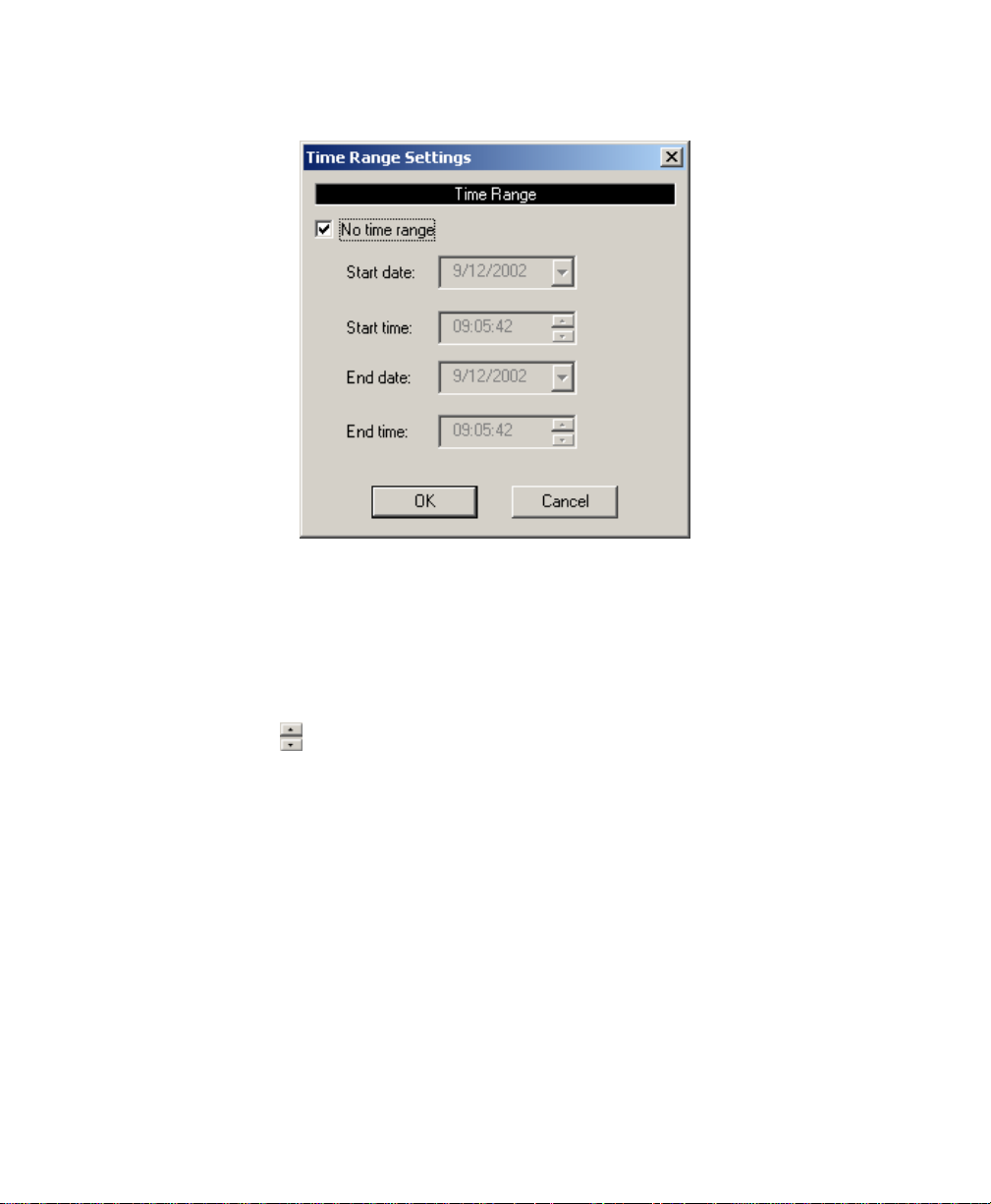
June 2004 Isis® Sonar User's Manual, Volume1
Figure 3-12. Time Range Settings dialog box
A check mark in the time range disables the fields. This is the default. When
the time range is unchecked, you can specify starting and ending dates from
a pop-up calendar accessed by clicking ▼ next to a date field. You can also
change the starting and ending times when the time range is unchecked:
Type over the existing numbers or else use the up and down directional
indicators (
) to set new times.
49
3.6.1.3 Isis Explorer Notify Menu
Use the choices in the Notify menu to inform the user of a change for:
Name, Start Time, End Time, Sensor Type, and Range Scale. When the
user is viewing files, if a change is detected, a message box will
automatically pop up. Figure 3-13 shows an example of a change in event
status.
Chapter 3: Using the File Menu
Page 64
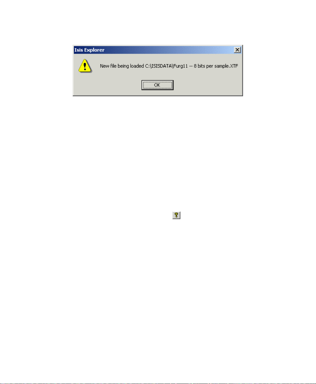
June 2004 Isis® Sonar User's Manual, Volume1
Figure 3-13. Example of a message identifying event status change
3.6.1.4 Isis Explorer Help Menu Functions
• Information box with Isis Explorer version number and copyright
information.
• Clicking the Question Mark icon on the Toolbar (Figure 3-11) is
equivalent to choosing Isis Explorer→Help.
3.6.2 Isis Explorer Toolbar Buttons
The Isis Explorer has two toolbar iconized buttons: a playback button and a
menu button. They are shown in Figure 3-11.
• Click the right-pointing arrow button (►) to play the selected file(s)
in Isis.
• Click the Question Mark button (
information box, which reveals the Isis Explorer version number and
copyright information.
) to display the About
50
3.6.3 Other Buttons and Fields in Isis Explorer
• Browse… button: Use this button to display the Windows file dialog
for navigating to the desired file path. The selected path is then
shown in the Path label box.
• File Sorting panel: The Isis Explorer tool provides five types of
sorting: primary, secondary, tertiary, ascending, and descending.
Primary, secondary, and tertiary choices offer drop-down list boxes
for setting the sorting item: by Average Heading (CMG), End Time,
File Name, Range Scale (Rng), Sensor Type, File Size, or Start
Time. The default is to sort by file name.
• The lower right corner of the main dialog box displays a colored box
to indicate the connection status with Isis: Green denotes an active
Chapter 3: Using the File Menu
Page 65

June 2004 Isis® Sonar User's Manual, Volume1
connection, and yellow denotes an inactive connection. See
Figure 3-11.
• [End] key behavior under Isis Explorer — If you have more than
one file selected in your Isis Explorer list, and you press [End] to go
to the end of the currently scrolling file, Isis Explorer does not
automatically go on to play back the next file in your list. Instead, the
file that was scrolling stops scrolling at the end of file. The purpose
of this [End] key behavior under Isis Explorer is to make it possible
for you to see the last part of your current file, at your leisure,
without having Isis Explorer jump to the next file right away. To
make Isis Explorer play the next file in your list when you are at the
end of the currently scrolling file, press [End] again (that is, press
[End] [End]).
3.6.4 Playing Back a Selected File or Files
Once the files have been sorted, the user can select one or more files to
play in Isis. If one file is selected and the Isis Explorer Play button is clicked,
or if you press ENTER, the file plays once. If more than one file is selected
and the Play button is clicked or the ENTER key is pressed, the set of files
plays in the top-to-bottom order shown in the listbox and then stops after the
last file finishes playing. During this loading process, Isis Explorer displays a
progress control and stop button message box (Figure 3-14):
51
Figure 3-14. Progress control and stop button message box
After Isis Explorer loads the specified files, Isis displays the filename for the
file that is currently being played. Double-clicking a selected file also plays it
back in Isis.
The user can select a file and drag it into the Isis workspace. While the file is
displaying the data, the user can pause the display from within Isis.
Isis yields “play” preference to the Isis Explorer tool. If Isis is launched and a
data file is being displayed when the Isis Explorer tool is running, then if the
Chapter 3: Using the File Menu
Page 66

June 2004 Isis® Sonar User's Manual, Volume1
user chooses a file in the Isis Explorer tool and either double-clicks the
filename or clicks the right-arrow Play button, the file in Isis that is currently
playing will stop and the new file will be played.
After one or more files are called from Isis Explorer and played back in Isis,
the highlighting of the file(s) in Isis Explorer changes to green to indicate the
file that Isis currently is playing back. See Figure 3-11 for an example of this.
The highlighting status remains in effect for the current session of Isis
Explorer.
52
3.7 Go To
Go to positions the current file at specific places in the playback file. Go to has
these options: Start, End, Ping, Time , Location , KP, Event (grayed out), Next
file in time, Previous file in time, and Specify Search Wildcard.
3.7.1 Start
This option positions the current file at the first ping. The [Home] key is the
keyboard shortcut for this operation.
3.7.2 End
This option positions the file at its end. The [End] key is the keyboard
shortcut for this operation. This option is also useful for displaying the last
section of a file. To play back the last section of a file, press [End], then
press [PageDown] to see the last 500 pings of the file.
Note: If you press [End] while a waterfall is running, it moves to the end of
the file and stops. It is not in Pause mode; it is in end-of-file mode. It
will not restart if you press SPACEBAR, even if At End of File→Go
Back to Start has been enabled from the File menu. To restart the
file, press [PageDown] or re-open the file from the File menu or
choose At End of File→Go to Next File in Time (if another file
already had been loaded).
3.7.3 Ping
This option allows the file to be positioned at a user-specified ping number.
This is handy if you have identified a location or an object in your file in
terms of its ping number.
If the specified ping number is greater than the number of pings in the file,
the file will be positioned at its end.
Chapter 3: Using the File Menu
Page 67
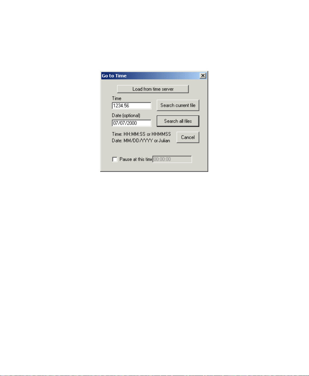
June 2004 Isis® Sonar User's Manual, Volume1
3.7.4 Time
Use the Go to Time option to go to the specified point either in the current
file or all files. The default is to Search all files.
Figure 3-15. Go to Time dialog box
You specify a time according to standard hour, minute, and second time
format. The keyboard shortcut is ALT+T to get this dialog box.
If the specified time is earlier or later than the first or last time in the file, you
will get an error message indicating that your choice of time is out of range.
(“Time is before or past the start of the current file.”)
Typing a time such as 07 will cause the system to search for time 07:00:00.
In other words, Isis appends as many zeroes as needed.
If you have RAMP support, you will also see an option in the Go to Time
dialog box to Load from time server.
If you put a check mark in the box labeled Pause at this time, you can then
type in a time that will act as a trigger to have Isis pause its playback when
that time is reached.
53
3.7.5 Location
Isis can begin displaying imagery at a ping that is closest to a location that
you specify with the Go to Location command. (This command can also be
Chapter 3: Using the File Menu
Page 68
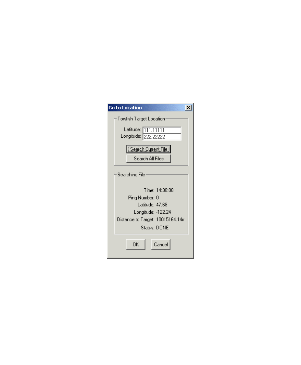
June 2004 Isis® Sonar User's Manual, Volume1
initiated from within ROVFlight with the Lookup Location in Isis button and
from within Target with the Playback in Isis command.)
When you select Go to Location, Isis prompts you to specify the location in
northings and eastings or in latitude and longitude depending on the
navigation coordinate system of the currently loaded data file. Once the
location is specified, you can elect to search only the currently loaded file or
all of the files in the same directory as the currently loaded file.
54
Figure 3-16: Go To Location dialog box
In either case, Isis will do a complete search to find the ping whose centertrack position is closest to the specified location. When the search is
complete, the Go to Location dialog box displays information about the
chosen ping. You can then elect to go to the chosen ping by clicking OK. If
you don’t want to go to that position, click Cancel.
Chapter 3: Using the File Menu
Page 69
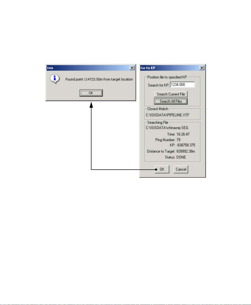
June 2004 Isis® Sonar User's Manual, Volume1
3.7.6 KP
Go to kilometers of pipe. If your data file contains tracked pipe, Isis will go to
that part of your imagery that contains the KP value you type in the dialog
box. An example is shown in Figure 3-17.
55
Figure 3-17. Kilometers of Pipe (KP) dialog box
3.7.7 Event
The Go to Event command is grayed out and unavailable in the current
version of Isis.
3.7.8 Next File in Time
This option causes Isis to look for the next file in your current directory that
contains the next latest navigation date and time, if such a file exists. The
keyboard shortcut for this action is ALT+[Page Up]. When searching for
next or previous file in time, if more than one file occupies the same point in
time, a selectable list is presented so the user can select the appropriate
file.
Chapter 3: Using the File Menu
Page 70

June 2004 Isis® Sonar User's Manual, Volume1
3.7.9 Previous File in Time
This option causes Isis to look for the next file in your current directory that
contains the previous earlier navigation date and time, if such a file exists.
The keyboard shortcut for this action is ALT+[Page Down].
3.7.10 Specify Search Wildcard
As an aid to narrowing your search for a previous or next file to play back,
choose this option. You can specify how each file name will start and/or end.
For example, specifying LINE*.XTF will cause Isis to only consider XTF files
which begin with the word LINE when searching for a file. Using ???E*.* will
match files which start with any three characters and have an E in the fourth
character of the name. If you check the Secondary wildcard box in this
dialog box, you can make Isis search for an additional set of files at the
same time.
3.8 Page Up
In a file being played back, this option repositions the file 500 pings ahead
(toward the end of the data file) from its current position. If fewer than 500 pings
remain before the end of the file is reached, the system positions the file at the
end of the file. (You are prevented from positioning the file past its end.) The
[Page Up] key is a shortcut to this command.
56
3.9 Page Down
In a file being played back, this option repositions the file 500 pings back (toward
the start of the data file) from its current position. If fewer than 500 pings remain
before the beginning of the file is reached, the system positions the file at the
beginning of the file. (You are prevented from positioning the file ahead of its
beginning.) The Page Down key is a short cut to this command.
Note: If Go back to Start is selected in the File→At End of File menu setting,
and you press Page Down near the end of the file, playback will jump to
the start of the current file.
3.10 At End of File
At End of File has two options: Go Back to Start or Go to Next File in Time.
Go Back to Start causes Isis to replay a file continuously. When the end of the
file is reached, Isis returns to the start of the file. Select the command from the
Chapter 3: Using the File Menu
Page 71

June 2004 Isis® Sonar User's Manual, Volume1
File menu to turn the feature on. Select it again to turn it off. When activated, the
command has a check mark next to it.
If you select Go to Next File in Time, Isis will automatically play back a series of
data files in chronological order. To determine where a file falls in chronological
order, each data file is opened and scanned for the first and last time/date in the
file. The file time and date set by the operating system has no bearing on its
playback order.
57
3.11 Print
This function is covered in Chapter 5, ‘Printing in Isis’.
3.12 Save Image
Save Image has two options: Write to Disk and Copy to Clipboard.
3.12.1 Write to Disk
This option saves a currently displayed image in a TIFF or a PCX bitmap
graphic format. Both formats are commonly used in PC environments. In
Isis, TIFF files are always gray-scale, whereas Isis can support color if you
save in the PCX format.
For either format choice, you can specify whether you want to capture the
Contents of the currently selected window or Imagery as it scrolls in
the window. For either form of saving, Isis displays a standard Save As
dialog box where you can specify a filename and directory for the image to
be saved.
To save imagery as a disk file
1. Access the option from the main menu: File→Save Image→Write to
Disk.
2. Choose a format (TIFF or PCX) and the kind of window to save (scrolled
or non-scrolled) by darkening radio buttons for these choices.
Chapter 3: Using the File Menu
Page 72

June 2004 Isis® Sonar User's Manual, Volume1
To stop saving imagery to a disk file
Depending whether you told Isis to save a single window or a scrolling
waterfall, Isis responds in one of two ways:
• If you chose to capture just the imagery in the current window, Isis
closes the Save As dialog box when you click OK on that dialog
box. At that point, Isis stops saving the imagery and closes the
saved TIFF or PCX file.
• If you chose to capture scrolling imagery, Isis closes the Save As
dialog box when you click OK on that dialog box, but the file to
which the imagery is being saved remains open until you re-access
the Write to Disk option from the main menu (File→Save
Image→Write to Disk) and click on that menu choice. Doing so
unchecks the previously checked Write to Disk status, tells Isis to
close the TIFF or PCX file to which imagery is being saved, and
displays a message informing you of this fact.
3.12.2 Copy to Clipboard
You can copy a currently displayed image to your Windows Clipboard. If you
copy an image to your Clipboard, you can paste it directly in another
application’s open file if that application accepts bitmap images from the
Clipboard without first having to be converted.
58
3.13 Exit
Use the Exit option to exit the Isis program. If you have not changed any setting,
Isis will exit without prompting you to save your configuration. If you have
changed one or more settings in this session, Isis will ask you if you want to save
your configuration before exiting.
If you respond Yes to the prompted question, Isis saves all settings you have in
effect for this session. Additionally, the last directory used to read a file is saved
and restored at start-up. If you respond No, Isis ignores any changed settings
(does not save them) and exits. The next time you run Isis, Isis uses whatever
settings had last been saved from an earlier session.
Chapter 3: Using the File Menu
Page 73

June 2004 Isis® Sonar User's Manual, Volume 1
59
Chapter 4 Setting Up Isis To Record Data
Setting up Isis to record data involves working with three types of information:
• choosing an ensonifying device and identifying it to Isis
• choosing appropriate serial ports that Isis will used to get specific
navigation data
• choosing a file format in which Isis will save your data
Isis needs to know the parameters for all three of these areas in order to
be able to record successfully. All three areas are accessed from
File→Record Setup… on the main menu.
4.1 Sonar Setup
In Sonar Setup (from the main menu: File→Record Setup→Sonar Setup), you
configure Isis to work with a specific brand of sonar chosen from a list of sidescan sonar or multibeam brands. Part of the setup is to specify the sonar’s beam
width and frequency, whatever brand of sonar will be used. Frequency is only
displayed and stored. It is not part of any equation in Isis. The sonar beam widths
are used in measuring the length of objects in the Target utility (to compensate
for beam spread which causes small objects to be stretched along-track) and
beam pattern compensation (to compute the angle for boresite). The Isis
software program itself is completely passive and provides no control over the
sonar. Thus, all values set in
current setting.
Even though Isis is passive with respect to direct control over a sonar, Isis can,
for certain kinds of sonar, use special control programs to indirectly augment the
control over sonars that Isis lacks directly. Prominent among these server control
programs are server control programs that Triton Elics makes for the SIS-1000,
DF_-1000 and SeaBat 900
mode in Isis, Isis will run a corresponding sonar control program for the sonar
selected in Isis. For more about these interactions of Isis to various sonars, see
‘Working With Specific Sonars’ in Appendix I (Isis User’s Manual, Volume
2).
Isis usually acquires sidescan and subbottom data from the DSP board in the Isis
system. Multibeam bathymetry is acquired via a serial port.
Sonar Setup should only indicate the sonar’s
x sonars. In most cases, when you activate Record
Chapter4: Setting Up Isis to Record Data
Page 74
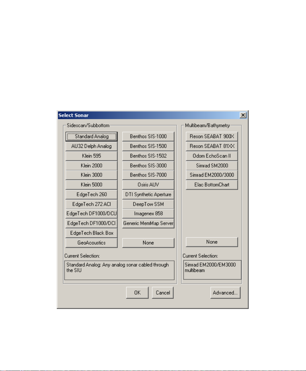
June 2004 Isis® Sonar User's Manual, Volume 1
4.1.1 Setting Up for a Sidescan or Subbottom Sonar
Sidescan sonars and subbottom profilers are frequently used with Isis and
hence represent the most common choice for recording.
To set up a sidescan or subbottom profiler for Isis
1. From the File menu choose Record Setup→Sonar Setup.
The system displays the Select Sonar dialog box (Figure 4-1).
60
Figure 4-1: Select Sonar dialog box
Chapter4: Setting Up Isis to Record Data
Page 75
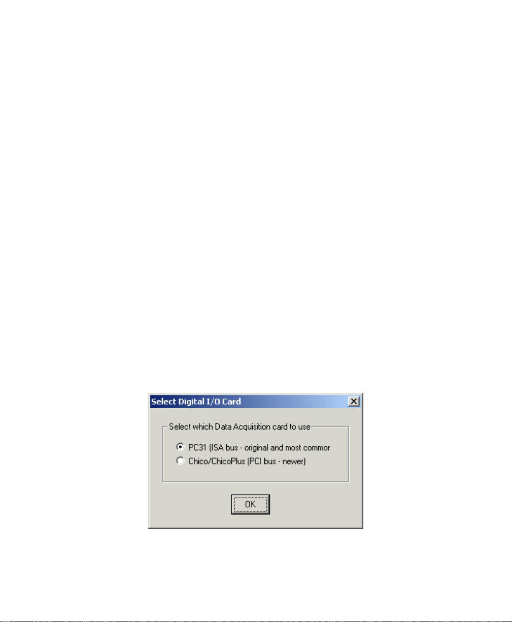
June 2004 Isis® Sonar User's Manual, Volume 1
As Figure 4-1 shows, you can select from two general categories of
sonars: sidescan (listed in the first two columns) or multibeam (listed in
the last column).
2. From the sidescan/subbottom group choose the brand of sonar you are
going to use.
When you make your choice, the system might display the Select Digital
I/O Card dialog box (Figure 4-2), depending on which sonar you choose.
Isis displays such a dialog box if you choose any of the following brands
or models:
• Standard Analog
• Klein 595
• Klein 2000
• EdgeTech 260
• EdgeTech 272 ACI
• EdgeTech DF1000/DCU
• EdgeTech DF1000/DCI
• EdgeTech Black Box
In the sonar-dependent Select Digital I/O Card dialog box, you can
choose either a PC31 or a Chico type of digital I/O card to use with
your sonar. Either type of I/O card can be used with any of the
aforementioned sonars.
The Select Digital I/O Card dialog box does not apply to the
multibeam choices.
Standard Analog is the default selection.
61
Chapter4: Setting Up Isis to Record Data
Page 76

June 2004 Isis® Sonar User's Manual, Volume 1
Figure 4-2. Select Digital I/O Card choice dialog
After you choose a sonar type (and, potentially, a type of digital I/O card),
the Isis software displays the Sidescan Sonar Information dialog box
(Figure 4-3).
62
Figure 4-3. Sonar Information dialog box for side-scan or subbottom
profilers
In the top left area of the Sonar Information dialog box, you can select a
channel to be added, edited, or deleted. Unnamed channels are designated
<available chan>. The Edit Delph Config File button appears in this dialog
box only if you chose
(Figure 4-1). You can also assign specific values for
Beam Angle
Chapter4: Setting Up Isis to Record Data
, Beam Width, Tilt down angle, and/or Name of Server in the
AU32 Delph Analog from the Select Sonar dialog box
Frequency, Horiz.
Page 77

June 2004 Isis® Sonar User's Manual, Volume 1
available text boxes. Table 4-1 explains the options. You can use the arrow
keys on your keyboard to scroll through the list if the values go beyond the
edges of the text box. You can modify the text in any of the boxes visible
above (including the upper left box of selected channels, by way of the
Channel Setup Edit button).
Table 4-1. Sonar information options
Option Meaning and Comments
63
Sonar Name
Frequency
Horiz. Beam
Angle
Beam Width (3dB)
This text box identifies the name of the currently selected
sonar and a short description of it.
Each channel can be set to whatever frequency, in kilohertz,
you want to use for your data survey, within the range limits
appropriate for the type of sonar you are using. The default is
100 kHz. Each channel in your channel list (top left corner)
has a frequency associated with it. If you have more than one
channel, all of the frequencies appear in the
box, separated by commas. The leftmost frequency in the
frequency list is associated with the topmost channel in the
channel list; the next frequency is associated with the next
specified channel, and so on for the entire list of named
channels.
This is the horizontal width, or thickness, of the channel’s
beam, expressed in degrees. The default is one degree. You
can adjust the beam angle within the limits of your sonar
type. Narrower beams have greater range but yield less
resolution, and vice versa. As with the frequency list, Horiz.
Beam Angle
order corresponding to the named channels. Where more
than one angle is listed, they are separated by commas.
This is the vertical, angular spread of the channel’s beam as
measured between the half-power points. As with frequency
and horizontal beam angles, the values in the text box read
from left to right and are assigned to the named channels
listed from top to bottom.
values in the text box are listed in left-to-right
Frequency text
Chapter4: Setting Up Isis to Record Data
Page 78
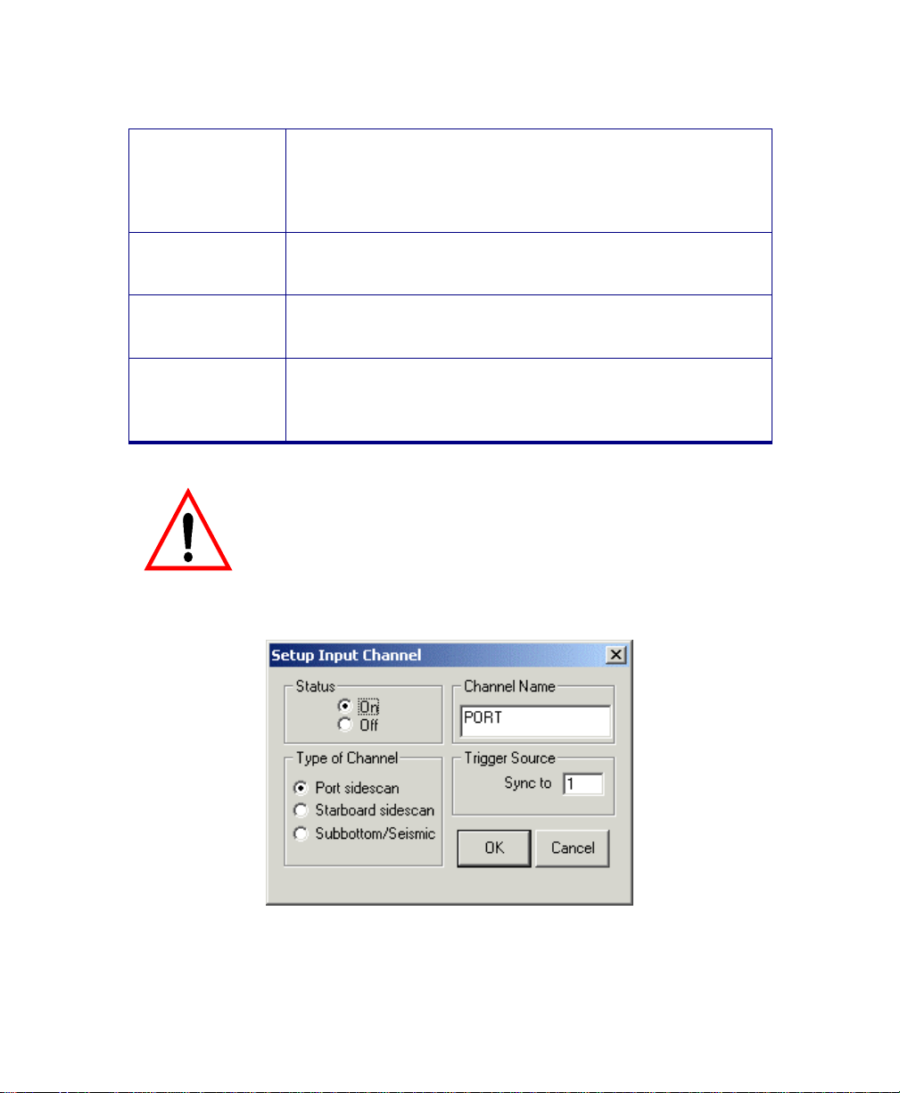
June 2004 Isis® Sonar User's Manual, Volume 1
64
Tilt down angle
Name of Server
Channel Setup
Edit
Edit Delph Config
File
You access the Setup Input Channel dialog box (Figure 4-4) from the Sonar
Information dialog box (Figure 4-3). Table 4-2 explains the options shown in
Figure 4-4.
This is the direction you are aiming a given channel. The
direction is expressed in degrees offset from an imaginary
horizontal plane corresponding to the surface of the water,
viewed flat. The listed angles correspond to the named
channels (left to right and top to bottom, respectively).
This is executable software designed to recognize different
sonar types so that certain properties of the sonar can be
correctly routed to the right place on the DSP board.
If you are adding, deleting, or otherwise editing a channel,
choose
ancillary dialog box (Figure 4-4).
Clicking this opens a file called CONF24T.DAT. In this file
you can change the I/O address and IRQ settings to match
those of your AU32 Delph Analog board. The file can be
edited with a standard text editor such as NotePad.
Be sure to back up the CONF24T.DAT file before
you change anything in it! The only thing you
should change in this file is the IRQ setting
and/or the I/O address setting! Leave everything
else alone!
Edit from the Channel Setup box to display an
Figure 4-4. Setup Input Channel dialog box
Chapter4: Setting Up Isis to Record Data
Page 79

June 2004 Isis® Sonar User's Manual, Volume 1
Table 4-2. Setup Input Channel options
Option Meaning and Comments
65
Status
Channel Name
Type of Channel
Trigger Source
For more information on specific types of side-scan or subbottom sonars,
please refer to
Isis User’s Manual, Volume 2.
The channel can be turned
been specified as
listed. This is the order that Isis will expect to receive the
data.
In this text box should be the name of the channel that
reflects the type of data you will acquire on the channel
specified in Type of Channel. You can also specify a
frequency to go with the channel: Type a space after the
channel name and then a number representing the
frequency. Example: PORT 123. In the Sonar information
dialog box, the system will update the
you.
Specify whether this channel will be dedicated to port sidescan, starboard side-scan, or subbottom/seismic data. The
Channel Name will change according to the Type of
Channel
Specify the trigger channel to which this channel will be
synchronized. Each synchronization channel requires an
embedded trigger and, therefore, a separate SIU4.
you choose.
On are numbered in the order that they are
‘Working With Specific Sonars’ (Appendix I) in the
On or Off. Channels that have
Frequency text box for
4.1.2 Advanced Record Setup
If you will be using several different sonars and multiple Isis sessions
simultaneously on your data survey, Isis provides a way to optimize and
separate existing memory-mapped files in those sessions. You do this from
the File menu:
Chapter4: Setting Up Isis to Record Data
Record Setup→Sonar Setup→Advanced (Figure 4-5).
Page 80

June 2004 Isis® Sonar User's Manual, Volume 1
Figure 4-5. Advanced Record Setup dialog box
66
Here are two examples that show how this feature might be used:
Isis session 1: Set Memory-mapped file no. to 0 and DSP
•
Device Index
bathy and any sidescan.
Isis session 2: Set Memory-mapped file no. to 2 and DSP
•
Device Index
any sonar through ChicoPlus).
Both sessions can now run simultaneously without conflicting with each
other.
to 1. Configure this session to use SBAT81XX for
to 2. Configure this session to use Klein 2000 (or
4.1.3 Setting Up for a Multibeam Sonar
Multibeam sonars, such as the Reson SeaBat, have their own set of
parameters to be customized. A feature found in all of the multibeam sonar
dialog boxes in Isis is an option to enable or disable the automatic opening
of a bathymetry confidence window. From the main menu, the bathymetry
Chapter4: Setting Up Isis to Record Data
Page 81

June 2004 Isis® Sonar User's Manual, Volume 1
67
confidence window can also be summoned from
Control→Bathymetry Confidence
To set up a multibeam sonar for Isis
1. Choose
2. Choose any of the multibeam types shown in the right column.
The system displays a dialog box for your chosen multibeam sonar.
For more information on specific types of multibeam sonars, please
refer to
Isis User’s Manual, Volume 2
Sonar Setup from Record Setup of the File menu.
‘Working With Specific Sonars’ (Appendix I) in the
(Figure 10-31).
.
Windows→Status and
4.2 Serial Port Setup
Isis uses serial COM ports to acquire navigation, towfish telemetry and other
time-series information (for example, magnetics, gravity, etc.). Normally these
data are transmitted by a GPS receiver, integrated navigation computer, or by
the towfish itself.
With the Serial Port Setup dialog box, you can specify the serial navigation and
telemetry interfaces. An Isis system can have up to 16 serial COM ports.
The baseline Isis system comes with two COM ports: COM1 and COM2. Some
Isis systems do not have a PS/2 style trackball. In that case, COM2 is taken by
the trackball.
To access the Serial Port Setup dialog box:
1. Choose
The system displays the Serial Port Setup dialog box (Figure 4-6).
File→ Record Setup→Serial Ports.
Chapter4: Setting Up Isis to Record Data
Page 82

June 2004 Isis® Sonar User's Manual, Volume 1
Figure 4-6: Serial Port Setup dialog box
68
The panels in the Serial Port Setup dialog box have the following meanings:
• Serial Port
may have fewer than 16 COM ports, so your choices are constrained by
the number of actual COM ports installed on your system. Therefore,
select a COM port available to your system.
• Status
unchecked). When Status is off, Navigation/Telemetry Template and Port
Settings areas are dimmed out and therefore unavailable. They become
available when Status is On.
• Port Settings
to 300), Data Bits (7 or 8), Parity (NONE, EVEN, ODD, or MARK), and
Stop Bits (1, 1.5, or 2). The most typical port settings to use with Isis
are:
Chapter4: Setting Up Isis to Record Data
(radio buttons) — COM 1 through COM 16. Your system
(check box) — Status is either on (On checked) or off (On
(area) — Here you can set the Baud Rate (115200 down
Page 83

June 2004 Isis® Sonar User's Manual, Volume 1
Baud Rate: 4800 and 9600 (commonly used by GPS receivers)
Data Bits: 8
Parity: NONE
Stop Bits: 1
• Navigation/Telemetry Template
template has been specified, its name appears here, in which case it
becomes the template Isis uses to parse the incoming
navigation/telemetry strings for this port. Figure 4-6 shows the telemetry
template that appears when HYPACK has been selected. Refer to
(buttons and text area) — If any
Appendix D, ‘Serial Interfaces,’ for guidelines on building a
template. As a setup convenience, if you click on any of the
Navigation/Telemetry Template buttons, Isis will insert the chosen
template name into this template text box and use it with the assigned
serial port.
The following templates are available from the buttons in this area:
• SeaBat #1, #2. The templates for the Reson single-head (#1) and
dual-head (#2), multibeam bathymetric profilers, respectively.
• EchoScan. The template for the Odom EchoScan multibeam data.
• ELAC. The template for the Elac Bottomchart.
• NMEA0183. This template specifies the automatic interpretation of
some standard NMEA0183 formats received by Isis over a serial
port. Refer to
‘How Isis Works with NMEA0183 Strings’ in
Appendix D of the Isis User’s Manual, Volume 2, for a discussion
of the NMEA0183 interface.
• HYPACK. The template corresponds to HYPACK’s isis.dll serial port
interface. HYPACK is a product of Coastal Oceanographics.
Note: When running HYPACK and Isis on the same computer, do not
specify a serial port for HYPACK. Use the Configure→HYPACK DDE menu
setup instead.
• TSS. The template for the TSS brand of a motion reference unit.
• POS/MV. POS/MV template for a TSS motion reference unit. This
supports the Simrad.
Note: If you select POS/MV, a warning is displayed that the attitude
should be in SIMRAD sonar format.
• Seatex MRU. The template for the Seatex motion reference unit.
69
Chapter4: Setting Up Isis to Record Data
Page 84

June 2004 Isis® Sonar User's Manual, Volume 1
70
• Convert Lat/Long to UTM
option is included and enabled with this Isis system, Isis will convert
Latitude and Longitude, as acquired over a serial port, to Universal
Transverse Mercator (UTM) coordinates. This conversion option
should be used as a last resort. Conversion to UTM is always best
done by an integrated navigation system. See the explanation for
Setup UTM button, next.
• Setup UTM
(enabled), this button becomes available. Clicking the button
displays a dialog box where you can configure for UTM or RD. A
sample appears in Figure 4-7.
(button) — If Convert Lat/Long to UTM is checked
(check box) — If a special navigation
Chapter4: Setting Up Isis to Record Data
Page 85

June 2004 Isis® Sonar User's Manual, Volume 1
Figure 4-7: Setup UTM dialog box
• Filter Speed Input (check box) — When Isis is in Record mode,
Isis computes speed input. You can filter speed “on the fly”
(Figure 4-8).This is convenient because it lets you bypass the
Record Setup menu in Isis (a menu which is unavailable to you when
you are playing back imagery).
71
Figure 4-8: Serial Speed Filter Setup
When Isis is in Record mode, speed filtering occurs when speed filtering
is turned on and speed is received into Isis by either of the following
means:
• Computed by Isis from XY or Lat/Long position updates.
• Received from any NMEA0183 device.
You can turn this feature on or off by checking or unchecking the choice.
If you enable the feature, you should also set the minimum and
maximum speeds accessible by clicking the Setup Filter… button and
setting your speed range. Note that speed filtering is only available when
Isis is in Record mode.
Chapter4: Setting Up Isis to Record Data
Page 86

June 2004 Isis® Sonar User's Manual, Volume 1
Speed is filtered according to the following formula:
1. Speed is forced to be between the min and max values as set by the
user.
2. Speed is smoothed by taking 90 percent of the previous speed and 10
percent of the new (just received) speed.
3. The amount of time that has elapsed between speed updates is
computed. If the amount of time is greater than 0 seconds and less than
60 seconds, then speed is further adjusted as follows:
• Acceleration = (new speed - previous speed) / (time difference)
• Adjustment = Acceleration / 2
• NewSpeed = NewSpeed + Adjustment
This has the effect of predicting speed based on the observed
acceleration. Speed is predicted by extrapolating between the current
update and the next expected update, assuming that updates occur
sequential in time.
4. The speed is checked again to verify that it is between the min and max
allowable range.
Navigation latency
milliseconds, that it takes to get navigation data from your navigation receiver to
Isis, you can compensate for this lag time by specifying the latency here, in
milliseconds.
(button) — Clicking Test displays a window indicating which COM ports, if
Test
any, have been allocated for use. (MMF is the ASCII-only serial data being
passed to Isis via a memory-mapped file.)
(text box) — If you know the amount in time, in
72
Chapter4: Setting Up Isis to Record Data
Page 87

June 2004 Isis® Sonar User's Manual, Volume 1
Figure 4-9: Partial view of COM Port Test box before ports are
assigned
73
4.3 File Format Setup
As of Isis version 4.32, Isis can read a format called TRA, also from Triton Elics
International. However, Isis cannot write TRA files.
Note: When reading TRA files, if information can’t be found in the
corresponding PAR file, Isis displays a warning.
In the File Format dialog box, you can specify the file format Isis will use to save
your data.
Chapter4: Setting Up Isis to Record Data
Page 88

June 2004 Isis® Sonar User's Manual, Volume 1
74
Figure 4-10: File Format dialog box
Here’s what the various parts of File Format dialog box mean:
• File Format — Save in Q-MIPS, XTF, SEG-Y format. Refer to Appendix
B for a description of these formats. SEG-Y format is an Isis option,
available only if it has been purchased for this system.
• Media — Save to a random-access disk or to Exabyte tape. Isis uses
true SEG-Y tape format and a modified SEG-Y format for disk storage.
Disk and Tape Q-MIPS formats are equivalent. Isis can read and write
long file names, not just DOS 8.3 format, to either medium.
• Sample Size to Record — Isis can save 8-bit or 16-bit data. While 8-bit
data storage conserves mass-storage space,16-bit data storage retains
a greater dynamic range. Isis displays 8 bits of imagery.
Chapter4: Setting Up Isis to Record Data
Page 89
June 2004 Isis® Sonar User's Manual, Volume 1
p
Samples per Channel to Record — Specify the number of samples that Isis will
record for each ping and each channel. Select a pre-defined number or type a
number in the Custom box. The resolution of side-scan sonars rarely justifies the
storage of more than 2048 pixels per channel.
Processing Method— The Isis A/D processors usually digitize a greater number
of samples than is stored by Isis. Thus, downsampling is generally required. In
determining a pixel value to represent a group of samples, Isis can either take
the Maximum sample in the group or calculate the root-mean-square (RMS) of
the group. Max downsampling ensures that small bright objects will not be
removed by the downsampling process. RMS downsampling gives the most
accurate overall image of the seafloor.
If 16-bit data are saved, only 8 of those 16 bits will be
displayed. Use the Threshold slide bar in the Waterfall
window dialog box to shift the displayed bits.
Please be aware that VISTA software from Triton Elics
cannot process 16-bit data that used 4 channels to record
data.
If you wish to replay side-scan imagery on a Q-MIPS
system, it must be stored in Q-MIPS format with 1024
ixels per channel per ping.
75
Note: Do not confuse downsampling for display purposes with downsampling
for recording purposes. This section you are reading is limited to
downsampling for recording purposes. For a discussion of downsampling
for display purposes, see
• XTF File Header notes — has these three fields:
• Vessel name: optional user-provided info goes here.
• Survey area: optional user-provided info goes here.
8.4, ‘Downsample’.
Chapter4: Setting Up Isis to Record Data
Page 90

June 2004 Isis® Sonar User's Manual, Volume 1
• Operator name: optional user-provided info goes here.
The text from these three fields gets put into the XTF file, just after the file
header. This information also appears in Help→Get Info, in any saved file in
ASCII Report dialog (if XTF Notes is checked), and in hardcopy annotation
(if Print Notes on hardcopy is checked).
76
4.4 Start Recording
When you select Start Recording from the File menu, you can elect to run your
recording session either in Record Data mode or Display Only mode. If Display
Only is selected, Isis will begin to acquire and display imagery. If Record Data is
selected, the next dialog box displayed will be determined by the data format
selected in Record Setup from the File menu.
If you selected a disk format for your recording session, Isis displays a Windows
Save As dialog box. As soon as you specify the new file name, Isis will begin
saving acquired data to that file in the format specified in Record Setup.
Note: If a device fills during recording, Isis writes to a file called overflow.dat
(or overflow.xtf) on the D:\ drive; Isis then keeps looking for available
space to put the file.
If you selected tape as the data format for your recording session, the Tape Drive
Control dialog box is displayed. Refer to Figure 4-7 for a full description. This
dialog box provides a means for you to position the tape for recording as well as
playing back.
The dialog box has a set of buttons that control the tape drive located at the
selected SCSI ID. In an Isis system, a tape drive is a SCSI Device whose ID is
set at 3 or 4. A single tape drive in an Isis system will be ID 3. If there are two
tape drives in an Isis system, the lower drive will be ID 3 and the upper drive will
be ID 4.
If you plan to record to a tape that already contains data, it is important to
properly position the tape before you select the Record option. Use the Advance
to End of data option to position the tape so that no data will be overwritten.
If Record is selected when the tape is positioned at
the end of a file, any data on the tape beyond that
file will be overwritten.
Chapter4: Setting Up Isis to Record Data
Page 91

June 2004 Isis® Sonar User's Manual, Volume 1
After recording has started you can monitor the current size of the file from the
Switch File button at the right side of the Parameter Display window.
77
4.5 The Switch File Dialog Box
The Switch button is located in the Parameter window. Clicking Switch displays
the Switch File dialog box where you can specify the maximum size a file shall
have before a file switch will occur. The default is 200 MB. When a file reaches
200 MB, Isis closes it, creates a new name, and resumes saving to the new file.
When file names end in a number, and Switch is performed, the number is
automatically incremented for a new file name and saving continues in the new
file. This does not apply to files named in the JJJ-HHMMSS format. When using
that format, the time and date are always used to create the file name.
If saving to tape, the tape drive control software will automatically delete the
previous disk file (unless you override this choice) and continue saving the new
file with no break on the tape data stream. In this way, the hard disk behaves like
a 200MB cache for the tape data. The data on the tape is essentially one huge
file, with filemarks written only if you press Stop, or if you rewind the tape for any
reason.
Chapter4: Setting Up Isis to Record Data
Page 92

June 2004 Isis® Sonar User's Manual, Volume1
78
Chapter 5 Printing in Isis
You use the File→Print command to specify a hardcopy output device
and begin sending imagery to that device. Isis supports a range printers
and plotters that are not automatically supported by Windows. To Isis,
these are non-standard printers. Such a printer must be locally attached
to your Isis system in order to be able to print or plot to it from Isis.
Any printer that is directly supported by Windows can also be used in
Isis. In Isis, this is known as a standard printer and is labeled that way
in the Plotter Setup dialog box of Isis. Please note that because most of
these printers and Windows-based drivers are designed to work in a
page format only, they are not suitable for continuous printing.
5.1 Hardcopy Devices Supported by Isis
The Isis software directly supports the following hardcopy devices:
• Alden 9315CTP-999, version CB 1.70 PE 1.51 with 1024K
buffer
• EPC models 1086, 1086 Multiping, 8300, 9701, 980x/950x,
9502, 1086-MP and 9206 (the latter two models have network
interface capability)
• Raytheon TDU models 850, 1200, 2000
• Waverley 195, 200 (same as Dowty 195, Ultra 195 and Ultra
200), and 3640
The above devices do not require a special Windows software
driver.
Triton Elics tests these devices periodically. In all cases, communication
with the printer or plotter is performed over the computer’s parallel printer
port.
5.2 Setting Up a Plotter
Many plotters, and some printers, require a certain sequence of
operations to occur before the devices will run correctly in the Windows
environment. In general, you do these tasks:
1. Identify the device to Windows.
Chapter 5: Printing in Isis
Page 93

June 2004 Isis® Sonar User's Manual, Volume1
2. Select the device in Windows prior to running your application
(Isis, in this case).
3. Run the application and select the previously identified device as
the one to use for printing or plotting imagery.
You may have to use all three procedures shown next in order to print
from Isis.
Because of the “plug and play” nature of Windows, identifying your
plotter or printer to Windows is usually automatic.
Note: Before you set up a plotter, be aware that certain large format
(“A0”) plotters are not suitable for real-time printing due to their
often complex modes of operation and slow speeds, all of which
hinders fast output. The HP DesignJet and the HP models 650,
750, and 755 plotters are among these devices, as is the
CalComp Techjet 5500 (even though all these devices are
supported by Isis as a “standard” Windows printer).
To identify your plotter or printer to Windows, do the following:
1. Exit all applications.
2. Shut down Windows.
3. Power off the system.
4. Connect the plotter/printer to the Isis system on LPT1 and put
the plotter/printer on-line.
5. Boot the computer and run Windows.
At this point, you have made it possible for Windows to find your
printer or plotter, but you have not yet selected it to use with Isis.
79
5.3 Printing to a Windows Device
Once a device has been identified to Windows through the “plug and
play” process, you can use it in Isis and other applications.
To print/plot an image from Isis using the selected print device
1. Run the Isis application and play back some imagery.
Chapter 5: Printing in Isis
Page 94
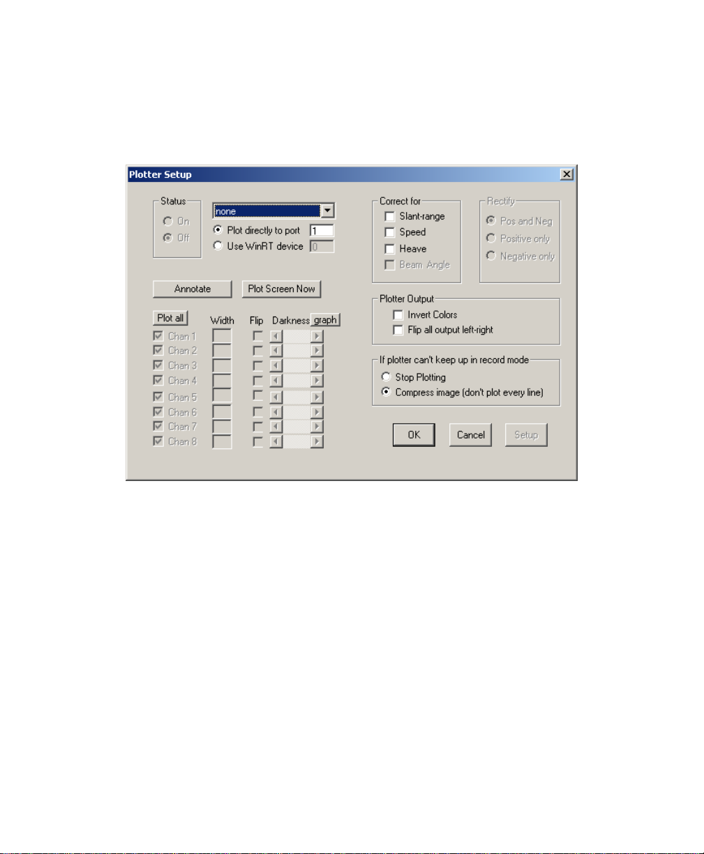
June 2004 Isis® Sonar User's Manual, Volume1
80
2. Choose the printer icon from the taskbar or choose
from the main menu.
Isis displays the Plotter Setup dialog box (Figure 5-1).
File→Print
Figure 5-1: Plotter Setup dialog box with default settings
3. Choose your plotter or printer from the combination box. The
default is
plotter/printer attached to your system; otherwise, problems may
result.
4. Put your
5. If you want to print a single screen of paused imagery, click
Screen Now
continuously scrolling mode, click
The image, including your Windows desktop, prints or plots to
the chosen device.
6. When you’re through printing, set
Plotter Setup box.
Chapter 5: Printing in Isis
none. Leave the choice as none if you do not have a
Plotter Status to On when you’re ready to print or plot.
; if you want to print your waterfall imagery in
OK.
Plotter Status to Off in the
Plot
Page 95

June 2004 Isis® Sonar User's Manual, Volume1
Note: [1] If your plotter manufacturer’s instructions suggest other
actions to the above general procedure, follow those instructions
first. Some plotters do not support the
option available in the Isis Plotter Setup dialog box. If that is the
case for your plotter, disable the
File→Print→Plotter Setup by clearing the check mark next to
the option.
[2] If you enable the Use WinRT device, different sessions of
Isis can each plot to their own plotter.
Plot directly to port
Plot directly to port option in
5.4 Activating Some Printer Drivers for Isis
Some printers, though they are recognized Windows, need additional
preparation before you can use them with Isis. In particular, the
button found in the Properties dialog box of Windows printers may need
to be enabled before you can print in Isis.
To enable a printer’s or plotter’s Apply button in Windows, do the
following:
1. From
2. From the list of available printers/plotters, select the device you
3. From the Settings→Printers menu selections, right-click the
4. Choose the General tab and inspect the settings shown there to
Start in Windows, choose Settings→Printers.
intend to use with Isis.
If the device is not in the list, choose
Windows menus to add the printer. Reboot your system after
adding a device to the list.
selected printer name and choose
The system displays a dialog box with several tabs in it.
make sure the
then you need to indicate a change, however trivial, in your
dialog box so that the Apply button is enabled. The simplest and
most harmless change you can do to enable that
to just press SPACEBAR while your cursor is in the
text box found on the
“change” and exit the Properties dialog box. This kind of
“change” is necessary because some printer drivers require that
Apply button is not grayed out. If it is grayed out,
General tab; then click OK to save your
Add Printer and follow the
Properties.
Apply
Apply button is
Comment
81
Chapter 5: Printing in Isis
Page 96

June 2004 Isis® Sonar User's Manual, Volume1
the device first be activated outside of the application where it
will be used.
At this point, you have instructed Windows to use a specific
plotter or printer with your application(s), with properties enabled.
5.5 Special Settings for Some Isis Plotters
Besides the foregoing printer setup requirements, some plotters have
additional special settings that should be made before you print in Isis.
They are explained next.
5.5.1 Alden 9315CTP-999 Plotter with Isis
Triton Elics has tested an Alden 9315CTP-999 plotter (serial
number 21137-999K; version CB1.70 PE 1.51 with 1024K buffer). It
works with the current version of Isis.
1. Follow the general procedure described in §
Plotter’
2. From the
software program, choose
Note: Although you should use the cables supplied by Alden, use
.
File→Print→Plotter Setup series of menus in the Isis
Alden 9315 as your plotter.
the non-SCSI cable to connect the Isis system to the plotter.
The Alden plotter can use SCSI cables with some
applications, but not with Isis. At the plotter, the non-SCSI
cable should be connected to the port labeled “parallel data
input” using the Centronics end of the cable. The DB-25M
end of the cable should be connected to LPT1 (parallel port)
on the Isis system.
5.2, ‘Setting Up a
82
5.5.2 EPC 1086 or Multiping Plotter with Isis
In addition to the general procedure (§5.2, ‘Setting Up a Plotter’)
the
EPC 1086 and EPC 1086 Multiping plotters plot single screens
or continuous waterfalls in Isis.
To print a single screen from Isis 2.11 or later, do the following:
1. Use the plotter’s status arrows to set the EPC plotter as follows:
• Data Type:
• Data Input: Parallel
Chapter 5: Printing in Isis
6-bit
Page 97

June 2004 Isis® Sonar User's Manual, Volume1
• Sweep: Forward
• Contrast: 0
• Repeat Ln: 1
• Shades: 64
• Width:
2048
2. Make any other selections at the EPC 1086 plotter suitable for
your plot session. You might want to save your sets of values as
a configuration set, using the plotter’s arrow keys to bring the
Save As Config_
view of the status window (where
x and Save Settings Config_x choices into
x is an integer), and pressing
Save on the plotter.
3. Run Isis, play back some data
4. Pause the waterfall by choosing File→Pause or by pressing
SPACEBAR.
5. On the Isis toolbar, click the printer icon to display the Plotter
Setup dialog box.
6. Choose EPC 1086.
7. In the Plotter Setup dialog box, make any other selections you
will be using for the 1086 plotter, such as the number of
channels to print, the paper width for each channel, and degree
of darkness.
8. Click the Status On radio button box if you want to monitor
plotter statistics in the session.
9. Click Plot Screen Now or click OK.
The system displays an EPC 1086 Setup Note dialog box to
remind you of the settings necessary for successfully plotting
with this plotter.
10. Click OK to acknowledge the Setup Note dialog box. Plotting
begins.
To print continuous waterfall images from Isis 2.11 or later
Plotting a continuous waterfall is exactly the same as plotting a
single screen except:
1. Set the Contrast at the plotter to a value of 15.
2. Do not pause the waterfall before plotting. (Plotting continues
until you close the Isis data file or exit Isis.)
83
Chapter 5: Printing in Isis
Page 98

June 2004 Isis® Sonar User's Manual, Volume1
84
See the procedure entitled
or later’
for the related settings.
‘To print a single screen from Isis 2.11
5.5.3 Using an EPC 9502 Plotter with Isis
Triton Elics has tested an EPC 9502 plotter (serial number 109). It
works with the current version of Isis.
1. Follow the general procedure described in §5.2.
2. From the File→Print→Plotter Setup series of menus in the Isis
software program, choose EPC 980X as your plotter.
Note: Unlike the EPC 1086 plotter model, the EPC 9502 does not
require that you make special settings at the plotter.
Consequently, you can print single-screen images or
continuous waterfall images from Isis without any changes.
5.5.4 Waverley 195 Plotter with Isis
As noted above, the Waverley 195 plotter is the same as the Dowty
195, Ultra 195 and Ultra 200 plotters. Before you can use any of
these plotters with Isis, check to see that your plotter is properly
connected and configured for Isis. You also may need to run some
simple tests if you don’t get any printed output. Use the following
procedures as a guide.
To connect the plotter to your Isis
1. Take a standard printer cable (not a straight-through DB25
cable) and connect one end to your LPT1 port.
2. Connect the other end to the parallel port interface labeled
“Centronics”.
To configure the plotter for Centronics mode of operation
1. Choose Standby mode.
2. Press [Shift] [ONLINE] until SBY appears.
3. Press SETUP twice.
4. Press ENTER until Centronics appears.
Chapter 5: Printing in Isis
Page 99

June 2004 Isis® Sonar User's Manual, Volume1
5. Press [Shift] [ONLINE] again to put the plotter on-line.
To configure Isis for the 195 or 200 plotter
1. Run Isis and start playing back a file. Press <SPACE>to pause
the playback.
2. Choose the printer icon on the toolbar at the top of the Isis
window.
3. Choose Waverley 195 as the printer.
4. Choose Plot All to print all channels across the page.
5. Verify that Fast Output is not checked.
6. Set Status to On.
7. Choose OK.
8. Press SPACEBAR to resume playback.
Note: If you finish using the plotter and then turn it off, Isis might
not be able to “see” the Sentinel attached to the system,
and Isis may stop running (or even be unable to start). The
solution is to turn the plotter back on or disconnect it.
To print (plot) the current Isis imagery with the 195 or 200
plotter
1. Reset your plotter to clear out any extraneous characters that
might still be in your plotter’s buffer.
2. Choose Plot Screen Now or click OK.
Note: If you have enabled Bottom Track (first return) from
View→Overlay of the main menu, your bottom tracking lines will
appear in your hardcopy.
If your imagery didn’t print after you clicked Plot Screen Now, you
may need to do some additional testing.
To test for general printing capability
• Run the test program that comes with your
Waverley/Dowty/Ultra 195 or 200 plotter.
85
Chapter 5: Printing in Isis
Page 100

June 2004 Isis® Sonar User's Manual, Volume1
If the test program fails, you will want to make another test that
checks to see if your printer port is wired correctly. You can
perform the tests either from DOS or Windows.
To verify from DOS that your printer port is working
1. Disconnect the plotter from your printer port and connect a
regular printer to the port.
2. At the DOS command prompt type:
ECHO This is a test > PRN
3. Press ENTER to redirect the string of characters to your printer.
Your printer should have printed the string “This is a test”.
To verify from Windows that your printer port is working
1. Disconnect the 195 plotter from your printer port and connect a
regular printer to the port.
2. From Windows run NotePad, WordPad, or any text editor.
3. In the text editor open a small text file or create one.
4. Have your text editor print the file.
If you are able to print from DOS or Windows using a regular
printer, then it may be that your Waverley/Dowty/Ultra 195 or 200
plotter either is not cabled correctly, not configured correctly, or
is not working. Recheck your connections and configuration
settings.
86
5.6 Sending Isis Imagery to a Plotter/Printer
When you select Print from Isis, the Plotter Setup dialog box is displayed
(Figure 5-1). From there you can make optional changes that will affect
your printed output. Table 5-1 explains the plotter setup options.
Table 5-1. Plotter Setup options
Option Meaning and Comments
Chapter 5: Printing in Isis
 Loading...