

Triton H200 Q Plus ECO aurastat TP461B, H200 Q Plus ECO auralite TP451HMB, H200 Q Plus ECO auralite TP452HMB, H200 Q Plus ECO aurastat TP463B, auralite TP518 Product Manual
...Page 1
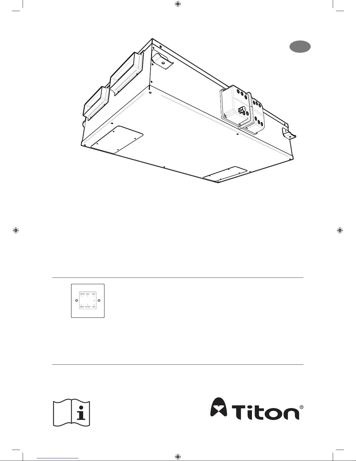
Product Manual
ventilation systems
auralite® compatible HRV units
H200 Q Plus ECO 204x60 TP451HMB
H200 Q Plus ECO Ø150 TP452HMB
H200 Q Plus ECO Ø160 TP453HMB
Heat Recovery Ventilation Units
aurastat® compatible HRV units
H200 Q Plus ECO 204x60 TP461B
H200 Q Plus ECO Ø150 TP462B
H200 Q Plus ECO Ø160 TP463B
Compatible with HMB units
auralite® TP518
LED Status Indicator
EN
Ventilation
System
Page 2

Warnings, Safety Information and Guidance
Important Information
Important: read these instructions fully before the installation of this appliance
1. Installation of the appliance and accessories must be carried out by a qualied and suitable
competent person and be carried out in clean, dry conditions where dust and humidity are
at minimal levels.
2. This manual covers the installation of the Heat Recovery Ventilation (HRV) unit
3. All wiring must conform to current I.E.E. Wiring Regulations and all applicable standards
and Building Regulations.
4. Inspect the appliance and electrical supply cord. If the supply cord is damaged, it must be
replaced by the manufacturer, their service agent or similarly qualied persons in order to
avoid a hazard.
5. The unit is supplied with a mains rated 3 core exible cord (PVC sheathed, brown, blue and
green/yellow 0.75mm²).
6. The appliance must be connected to a local double pole isolation switch with a contact
separation of at least 3mm.
7. The appliance must be earthed.
8. H200 Q Plus suitable for 230V ~ 50/60Hz single phase with a fuse rating of 3A.
9. auralite® & aurastat®, control & communication cable access is via the tted cable gland(s)
which are suitable for Ø3- 6mm cable.
10. auralite® & aurastat® control & communication cable - Unshielded 4 Core 18-24AWG Stranded, Tinned Copper.
11. Control & communication cables should not be placed within 50mm or on the same metal
cable tray as any 230V~ lighting or power cables.
12. Ensure all cable glands are fully tightened.
13. The unit must be stored in a clean and dry environment. Do not install the appliance in
areas where the following may be present or occur;
• Excessive oil or a grease laden atmosphere,
• Corrosive or ammable gases, liquids or vapours,
• Ambient temperatures above 40°C or below -5°C,
• Humidity levels above 90% or is a wet environment.
14. The appliance is not suitable for installation to the exterior of the dwelling.
15. This appliance can be used by children aged from 8 years and above and persons with
reduced physical, sensory or mental capabilities or lack of experience and knowledge if
they have been given supervision or instruction concerning use of the appliance in a safe
way and understand the hazards involved. Children should be supervised to ensure that
they do not play with the appliance. Cleaning and user maintenance shall not be made by
children without supervision.
16. Ensure that external grilles are located away from any ue outlet, in accordance with relevant Building Regulations.
17. The unit must not be connected to a tumble dryer or a cooker hood.
18. Precautions must be taken to avoid the back-ow of gases into the room from an open ue
appliance.
19. Ensure all ducting, condensate drain and associated pipe work is free from debris and
blockages before switching on the unit
2
Page 3
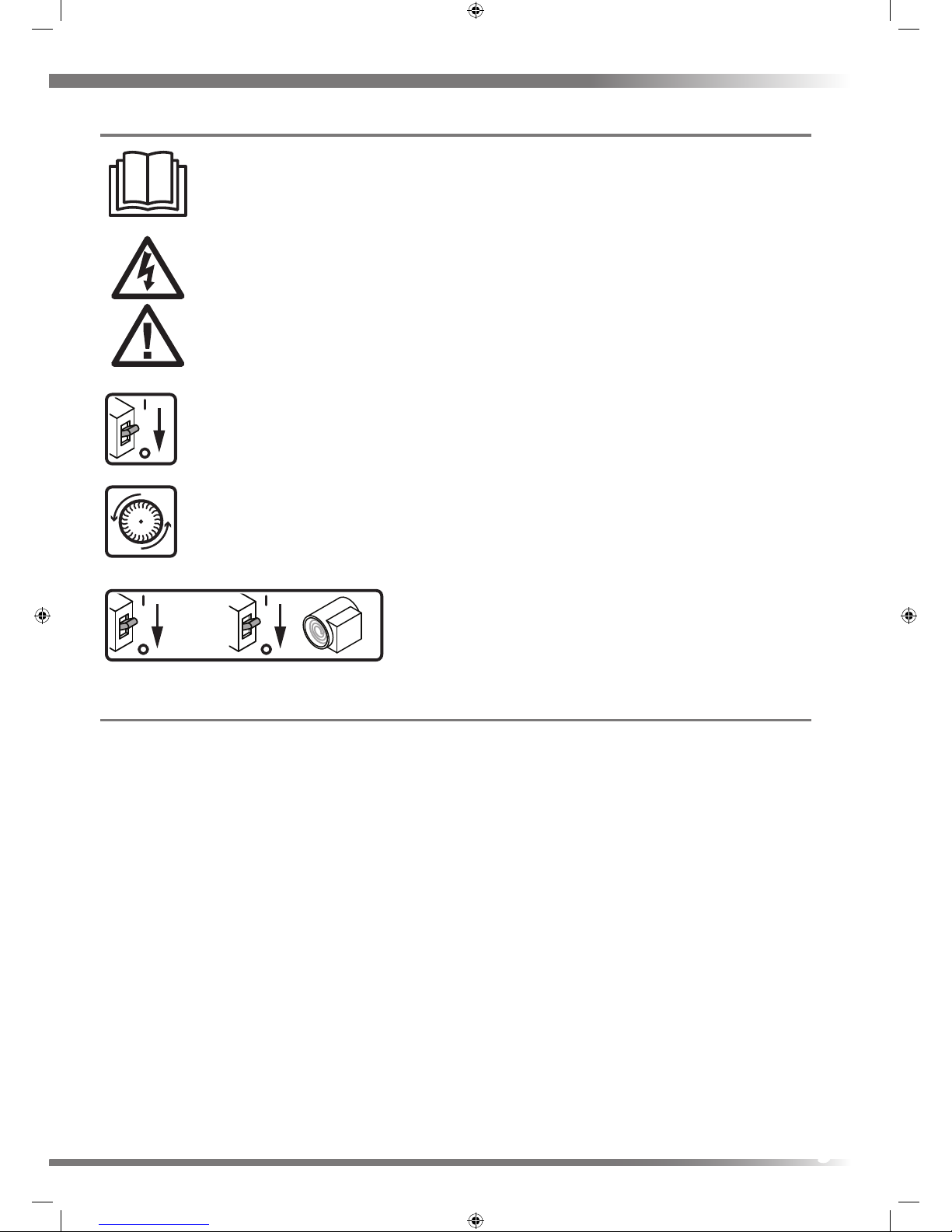
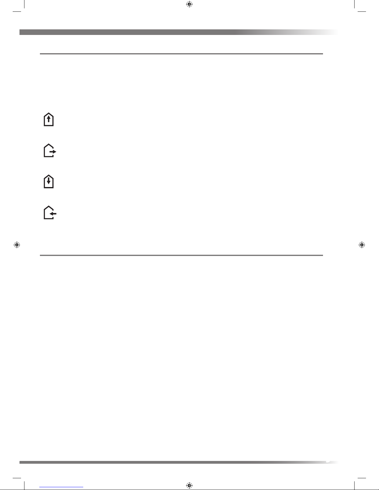
Explanation of symbols on the appliance.
Read instruction Manual.
Risk of Electric Shock.
General hazard safety alert.
Disconnect the mains supply before removing this cover.
Wait until all machine components have completely stopped before touching
them.
Disconnect the mains supply before removing this
cover.
&
Before obtaining access to terminals or removing this
cover, all supply circuits must be disconnected.
Titon Recommend:
1. A short piece of exible ducting, approximately 200mm long is used to connect the unit to the ducting system.
2. Any exible ducting used must be pulled taut.
3. A minimum distance of 200mm between the HRV unit and any sharp bends in duct work.
4. Ducting should be insulated where it passes through unheated areas and voids with the equivalent of at least 25 mm
of a material having a thermal conductivity of ≤0.04 W/(m.K) to reduce the possibility of condensation forming. Where
a duct extends externally above roof level the section above the roof should be insulated or a condensate trap should
be tted just below roof level.
5. Ducts within the building heated envelope between the external terminals and the unit’s From Atmosphere and To
Atmosphere ports should be insulated and wrapped additionally with a vapour barrier outside the insulation.
6. Where ducts pass through re barriers, they must be appropriately re stopped in accordance with the requirements
of Building Regulations.
7. A ducting condensate drain must be tted to vertical To Atmosphere duct work.
8. Ducting must be installed in such a way that resistance to airow is minimised.
9. Ducting connected to the From Atmosphere & To Atmosphere ports, must be to/from the external air outside the
building envelope.
10. Duct joints to the unit’s duct ports must be xed using a method that ensures a long term seal is achieved. If using a
short piece of exible ducting secure using a hose clamp, do not over tighten.
11. A minimum distance of 2m exists between the external supply and exhaust terminals .
+
3
Page 4

Contents
When this document
is viewed as a PDF the
headings & sub headings on
this page are hyper links to the content.
Additionally the page numbers in this
document are hyper links back to this
contents page.
Warnings, Safety Information and Guidance
Important Information . . . . . . . . . . . . . . . . . . . . . . . . . . . . . . . . . . . . . . . . . . . 2
Explanation of symbols on the appliance. . . . . . . . . . . . . . . . . . . . . . . . . . . .3
Titon Recommend: . . . . . . . . . . . . . . . . . . . . . . . . . . . . . . . . . . . . . . . . . . . . . .3
Product Information
Packaging Contents. . . . . . . . . . . . . . . . . . . . . . . . . . . . . . . . . . . . . . . . . . . . . . 5
Component Identication . . . . . . . . . . . . . . . . . . . . . . . . . . . . . . . . . . . . . . . . 5
Dimensions. . . . . . . . . . . . . . . . . . . . . . . . . . . . . . . . . . . . . . . . . . . . . . . . . . . . . 6
Installation
H200 Q Plus. . . . . . . . . . . . . . . . . . . . . . . . . . . . . . . . . . . . . . . . . . . . . . . . . . . 7
Condensate Drain . . . . . . . . . . . . . . . . . . . . . . . . . . . . . . . . . . . . . . . . . . . . . . . 8
Ducting Connections . . . . . . . . . . . . . . . . . . . . . . . . . . . . . . . . . . . . . . . . . . . . .9
Wiring Connections Access. . . . . . . . . . . . . . . . . . . . . . . . . . . . . . . . . . . . . . . . 9
Product Overview aurastat® Units TPxxxB
Control & Features . . . . . . . . . . . . . . . . . . . . . . . . . . . . . . . . . . . . . . . . . . . . . .10
Filter Covers . . . . . . . . . . . . . . . . . . . . . . . . . . . . . . . . . . . . . . . . . . . . . .10
Wiring Diagrams . . . . . . . . . . . . . . . . . . . . . . . . . . . . . . . . . . . . . . . . . . . . . . .11
Supply . . . . . . . . . . . . . . . . . . . . . . . . . . . . . . . . . . . . . . . . . . . . . . . . . . .11
Switching & Controls. . . . . . . . . . . . . . . . . . . . . . . . . . . . . . . . . . . . . . . 12
External Sensors. . . . . . . . . . . . . . . . . . . . . . . . . . . . . . . . . . . . . . . . . . . 15
Duct Heater . . . . . . . . . . . . . . . . . . . . . . . . . . . . . . . . . . . . . . . . . . . . . . . . . . .16
Fitting . . . . . . . . . . . . . . . . . . . . . . . . . . . . . . . . . . . . . . . . . . . . . . . . . . .16
Connection to Mains . . . . . . . . . . . . . . . . . . . . . . . . . . . . . . . . . . . . . . .17
Maintenance. . . . . . . . . . . . . . . . . . . . . . . . . . . . . . . . . . . . . . . . . . . . . .17
Overheating . . . . . . . . . . . . . . . . . . . . . . . . . . . . . . . . . . . . . . . . . . . . . .17
Commissioning aurastat® Units TPxxxB
HRV Controller Product Manual. . . . . . . . . . . . . . . . . . . . . . . . . . . . . . . . . . . 18
Product Overview auralite® Units TPxxxHMB
Controls & Features . . . . . . . . . . . . . . . . . . . . . . . . . . . . . . . . . . . . . . . . . . . . . . . . . . . . 19
Filter Covers . . . . . . . . . . . . . . . . . . . . . . . . . . . . . . . . . . . . . . . . . . . . . . . . . . . . . 19
auralite® . . . . . . . . . . . . . . . . . . . . . . . . . . . . . . . . . . . . . . . . . . . . . . . . . . . . . . . . 19
Auto Setback Speed. . . . . . . . . . . . . . . . . . . . . . . . . . . . . . . . . . . . . . . . . . . . . . . 19
Continuous Speed . . . . . . . . . . . . . . . . . . . . . . . . . . . . . . . . . . . . . . . . . . . . . . . . 19
Boost Speed with Overrun Timer . . . . . . . . . . . . . . . . . . . . . . . . . . . . . . . . . . . . 19
auralite® Boost Alert . . . . . . . . . . . . . . . . . . . . . . . . . . . . . . . . . . . . . . . . . . . . . . 20
Summer Bypass . . . . . . . . . . . . . . . . . . . . . . . . . . . . . . . . . . . . . . . . . . . . . . . . . . 20
SUMMERboost® . . . . . . . . . . . . . . . . . . . . . . . . . . . . . . . . . . . . . . . . . . . . . . . . . . 20
Automatic Frost Protection . . . . . . . . . . . . . . . . . . . . . . . . . . . . . . . . . . . . . . . . . 20
Integrated Humidity Sensor . . . . . . . . . . . . . . . . . . . . . . . . . . . . . . . . . . . . . . . . 20
Wiring Diagrams . . . . . . . . . . . . . . . . . . . . . . . . . . . . . . . . . . . . . . . . . . . . . . . . . . . . . . 21
Supply . . . . . . . . . . . . . . . . . . . . . . . . . . . . . . . . . . . . . . . . . . . . . . . . . . . . . . . . . . 21
auralite® . . . . . . . . . . . . . . . . . . . . . . . . . . . . . . . . . . . . . . . . . . . . . . . . . . . . . . . . 21
Switching & Controls. . . . . . . . . . . . . . . . . . . . . . . . . . . . . . . . . . . . . . . . . . . . . . 22
Commissioning auralite® Units TPxxxHMB
Controls. . . . . . . . . . . . . . . . . . . . . . . . . . . . . . . . . . . . . . . . . . . . . . . . . . . . . . . . . . . . . . 24
Control Parameters . . . . . . . . . . . . . . . . . . . . . . . . . . . . . . . . . . . . . . . . . . . . . . . 24
Continuous Supply & Extract Speeds: . . . . . . . . . . . . . . . . . . . . . . . . . . . . . . . . 24
Boost Supply & Extract Speeds: . . . . . . . . . . . . . . . . . . . . . . . . . . . . . . . . . . . . . 24
Boost Overrun. . . . . . . . . . . . . . . . . . . . . . . . . . . . . . . . . . . . . . . . . . . . . . . . . . . . 25
Humidity Sensor . . . . . . . . . . . . . . . . . . . . . . . . . . . . . . . . . . . . . . . . . . . . . . . . . 25
Controller Reset . . . . . . . . . . . . . . . . . . . . . . . . . . . . . . . . . . . . . . . . . . . . . . . . . . 25
Hardware Reset . . . . . . . . . . . . . . . . . . . . . . . . . . . . . . . . . . . . . . . . . . . . . . . . . . 25
Maintenance
Filter Replacement . . . . . . . . . . . . . . . . . . . . . . . . . . . . . . . . . . . . . . . . . . . . . . . . . . . . 26
How to Change Filters . . . . . . . . . . . . . . . . . . . . . . . . . . . . . . . . . . . . . . . . . . . . . 26
aurastat®Filter Change Alert Reset . . . . . . . . . . . . . . . . . . . . . . . . . . . . . . . . . . 26
auralite® Filter Notication Reset . . . . . . . . . . . . . . . . . . . . . . . . . . . . . . . . . . . 26
Routine Maintenance . . . . . . . . . . . . . . . . . . . . . . . . . . . . . . . . . . . . . . . . . . . . . . . . . . 27
Access to Interior for cleaning . . . . . . . . . . . . . . . . . . . . . . . . . . . . . . . . . . . . . . 27
Cleaning Interior . . . . . . . . . . . . . . . . . . . . . . . . . . . . . . . . . . . . . . . . . . . . . . . . . 27
Cleaning Exterior . . . . . . . . . . . . . . . . . . . . . . . . . . . . . . . . . . . . . . . . . . . . . . . . . 27
Service Record . . . . . . . . . . . . . . . . . . . . . . . . . . . . . . . . . . . . . . . . . . . . . . . . . . . . . . . . 31
4
Page 5
Product Information
The HRVs are Mechanical Ventilation with Heat Recovery (MVHR) units. They are designed for the energy ecient
ventilation of dwellings. The units are designed for continuous ventilation, exhausting stale moist air from bathrooms,
toilets, kitchen and utility rooms. As the stale air is extracted, the unit’s heat exchanger transfers heat, which would have
been wasted, to the fresh air being supplied to the bedrooms and living rooms.
Packaging Contents
Inspect the unit when taking delivery. Check the unit for damage and that all accessories have been supplied. Package
supplied with;
HRV unit x 1.
Mounting Bracket x 4.
M5x10mm Pan head screws x 8.
M5 Star washers x 8.
Product Manual x 1.
EuP Documents.
Any shortages or damage must be immediately reported to the supplier.
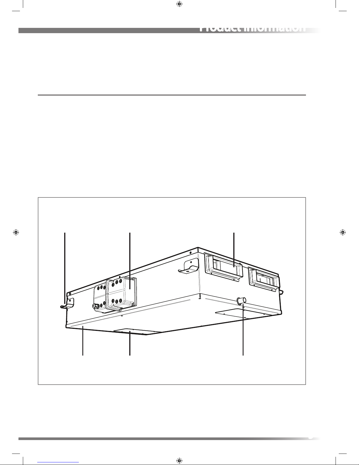
Component Identication
Duct PortMounting Bracket
Front Cover Filter Cover
Electronics Compartment
Condensate Drain
5
Page 6
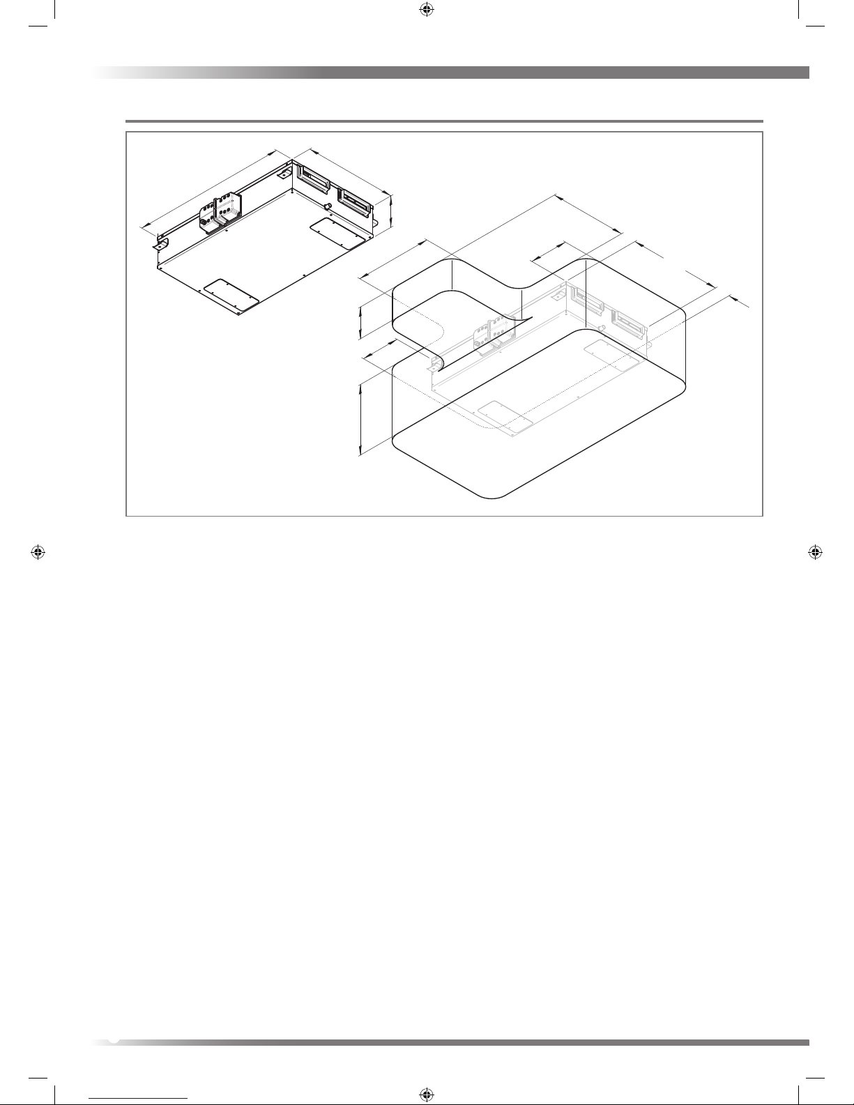
Dimensions
Service Void
500
250
250
100
100
400
1004
604
203
205455
H200 Q Plus DO NOT BOX IN UNIT
6
Page 7
Installation
H200 Q Plus
Read and observe the guidance & safety notices listed in Warnings, Safety Information and Guidance .
The units are designed to be mounted on the underside of a horizontal surface.
The mounting surface and xings must be suciently strong to support the unit. The unit is H200 32Kg,
Consider the positioning of electrical services and the Condensate Drain when siting the unit.
Ensure there is sucient access around the HRV Q Plus for future maintenance.
Do not ‘box-in’ the unit making access to the unit dicult for maintenance and repair.
The unit must be mounted plumb and level front to back and side to side.
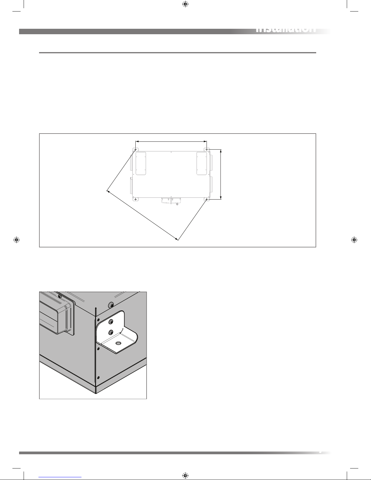
1. Position four Ø8mm xings in the mounting surface in the positions specied. Fixings must be suitable for the
mounting surface substrate and the weight of the unit. Fixings are not supplied due to the variation in materials. For
advice on suitable xings contact your local specialized xings dealer.
2. Fit the 4 mounting brackets to the sides of the unit with the M5 screws and M5 star washers, ensure all mounting
brackets are orientated as illustrated.
3. Secure the unit using Ø8mm xings Ensure the unit is plumb and level front to back and side to side.
Fixing Locations H200
925
(1128.75)
647
7
Page 8

Condensate Drain
The unit’s Condensation Drain Pipe must be tted and connected to the dwelling’s foul water drainage system in
accordance with the relevant building regulations.
Condensate output is a Ø21.4mm plastic pipe positioned on the end of the unit.
Drain pipe must be tted to the unit with a removable tting.
Drain pipe must incorporate a suitable trap, which must act as an air lock.
Must be adequately secured and be insulated with the equivalent of at least 25mm of insulating material with a
thermal conductivity of 0.04 W/(mK) if any part of the pipe passes though an unheated void
Condensate drain pipe must be installed to have a minimum 3° fall from the unit.
Titon recommend the use of diaphragm type waste valve in place of a conventional ‘wet’ trap which could dry out.
Such as, BRE certicate no. 042/97 ‘Hepworth Hepv0 Hygienic self sealing plastic waste valve’ recommended as an
alternative to traditional U-Traps.
8
Page 9
Ducting Connections
Read and observe the Warnings, Safety Information and Guidance.
The HRV unit has a labels with the icons indicating which port is which.
It is very important that ducting is connected to the correct ports in line with the icons below.
EXTRACT FROM DWELLING - This duct port is connected to the ducting that carries waste air from the ‘Wet Rooms’
to the HRV unit.
TO ATMOSPHERE - This duct port is connected to the ducting that carries the waste air to outdoors from the HRV
unit.
SUPPLY TO DWELLING - This duct port is connected to the ducting that carries the fresh warmed air to the
habitable rooms from the HRV unit.
FROM ATMOSPHERE - This duct port is connected to the ducting that carries fresh outdoor air to the HRV unit.
Wiring Connections Access
All wiring must conform to current I.E.E. Wiring Regulations and all applicable national standards and Building
Regulations. Read and observe the Warnings, Safety Information and Guidance.
The electronics compartment is mounted on the side of the unit. The compartment has two interlocking removable lids.
Remove all eight screws to remove both lids.
All wiring must be routed into the electronics compartment via the knock-outs and using cable glands or similar.
9
Page 10
Product Overview aurastat® Units TPxxxB
Control & Features
Filter Covers
The units are tted with removable lter covers on the front panel.
In depth information on the features of the aurastat units can be found in the HRV Controller Product Manual.
ventilation systems
EN
aurastat® HRV Controller Product Manual
10
Page 11

Wiring Diagrams
Supply
Supply wiring Ref EE167
230V~
2 Pole
Isolator
Fuse
11
Page 12

Switching & Controls
Supply wiring with switch inputs Ref EE166
The Switched Live (LS1, LS2) Boost(s) must be supplied via
the same circuit as used to power the unit.
A 3 (LS1 only) or 4 (LS1 &LS2) pole local isolator must be
installed. The Boxed Relay (Part No. TP505) may be required
to switch from other circuits.
Wet Room Light Switch
Kitchen Light Switch
230V~
4 Pole
Isolator
2 Pole
Isolator
Fuse
12
Page 13

Volt Free switch inputs Ref EE163
LIVE switch inputs Ref EE163
Switch Defaults
SW1 - Volt Free - Kitchen Boost.
SW2 - Volt Free - Wet Room Boost.
SW3 - Volt Free - SUMMERboost Control.
Switch Defaults
LS1 - 230V~ - Kitchen Boost
LS2 - 230V~ - Wet Room Boost
The Switched Live (LS1, LS2) Boost(s) must be supplied via
the same circuit as used to power the unit.
SW Live from Kitchen
SW Live from Wet Room
13
Page 14

Connections Ref EE165
Any of these switch arrangements can be used in
switch inputs SW1 to SW3 depending on their
conguration and the type of MVHR.
Volt-free control of SUMMERboost® using room
thermostat. TP509 Room Thermostat
Volt-free activation of Summer Mode using room
thermostat. TP509 Room Thermostat
Volt-free boost switching of MVHR using singlepole switches TP502, TP503, TP507 and / or
TP500/TP501 Humidistat.
There is a maximum of 10 single pole switches or
Humidistats that can be used.
TP506 Latching Summer Mode switch /
TP522 Latching SUMMERboost® switch.
1 2 3
T
L
Y1 Y2
T
L
Y1 Y2
14
Page 15

External Sensors
0-10V Sensor connections Ref EE161
If sensors are tted with switches ensure they are switched to VDC
Vin
GND
AO1
Vin
GND
AO1
Room Sensor 1
(default TP542 RSH
Room Humidity Sensor)
Room Sensor 2
(default TP541 RSC Room CO Sensor)
Additional Options:
TP540 RSQ Room Air Quality Sensor
TP543 RST Room Temperature Sensor
3-Way rotary switch Ref EE162
Switch Positions TP508 Three Position Rotary Switch
1 - Setback Speed
2 - Continuous Speed
3 - Boost Speed
For this conguration to function correctly;
S1-1 Needs to be set to a Kitchen or Wet Room Boost switch,
S1-2 Needs to be set to a Setback switch.
15
Page 16

Duct Heater
Using the factory tted PCB TPxxxB models only it is possible to control an external mains operated duct heater to prewarm the incoming fresh air supply. During periods of cold weather, this reduces the possibility of ice build-up within the
unit by raising the temperature of the incoming supply air. However there will be a signicant increase in electrical energy
use.
Fitting
1. The heater is designed for insertion into standard spiral steel ducting and is
xed to the ducting with screws.
2. The air must ow through the heater in the direction of the arrow (located
on the side of the heater close to the connection box).
3. The heater can be tted in either horizontal or vertical ducting. The
electrical connection cabinet can be freely placed facing upwards
or sideways to a maximum angle of 90°. Fitting with the box facing
downwards is NOT allowed.
4. The access opening in the heater must be equipped with a xed mesh or an
intake air device which makes it impossible to touch the element inside
5. A warning sign must be attached close to the air outlet, stating that the air
outlet must not be covered.
6. The distance from (to) the heater
to (from) a duct bend, valve,
lter, etc should correspond to
at least twice the duct diameter,
otherwise there is a risk that
the airow through the heater
is uneven which can cause
activation of the overheating
cut-out.
7. The heaters may be insulated in
accordance with valid regulations
for ventilation ducting. However,
the insulation material must
be incombustible. The cover of
the heater must be free from
insulation so that the type plate
is visible and the cover can be
removed.
8. The parts of the ventilation
system where heaters are
installed must be kept accessible
to allow replacement and service.
9. The distance from the heater’s
metal casing to any wood or
other combustible material must
NOT be less than 30 mm.
Duct Heater
Duct Heater Operational Ranges
300W
600W
900W
Permissible
Not permissible
Ø125mm
0
10
20
30
40
0 100 200 300 400
Air Flow (m³/hr)
0 100 200 300 400
Air Flow (m³/hr)
Temperature Rise (°C)
Ø160mm
0
10
20
30
40
Temperature Rise (°C)
mm W Part No.
Ø125 300 DH 125 300
600 DH 125 600
900 DH 125 900
Ø160 300 DH 160 300
600 DH 160 600
900 DH 160 900
Duct Heater tting orientation
16
Page 17

10. The maximum ambient temperature allowed is 40°C.
11. The air ow through the heater must have a speed of at least 1.5 m/s.
12. The maximum output temperature allowed is 40°C.
Connection to Mains
1. All wiring must conform to current I.E.E. Wiring Regulations and all applicable national standards and Building
Regulations.
2. The installation MUST be carried out by a suitably qualied competent person.
3. The duct heaters are designed to operate on single phase alternating current. See the wiring diagram for the
particular heater and the electrical data on the rating plate placed on the cover of the duct heater.
4. The duct heater must be connected to the mains supply with a xed installed round cable. The heater must be
equipped with a cable grommet or cable tting designed for the cable, which ensures that the electrical protection
class of the heater is retained. The standard design is IP43.
5. It must not be possible to switch on the power to the element unless the Q Plus unit is operating. An all phase breaker
or a double pole switch with a contact gap of at least 3mm must be included in the xed installation.
6. The duct heater is equipped with two overheating cut-outs (one with manual reset) designed to prevent overheating
when the airow is too low or in the event of a fault in the system.
7. A drawing must be attached inside the fuse box or on the wall of the service room. The drawing shows the rating of
the duct heaters and their location in the building, together with information about the measures to be taken in the
event that the overheat protection cutout(s) is activated.
Maintenance
No maintenance is required except a periodic functional test.
Overheating
When the overheating cut-out with manual reset has been activated, the following should be observed:
1. The heater must not be interfered with in any way, such as removal of the cover, except by an authorised electrical
tter.
2. Turn o the mains power.
3. Investigate carefully the reason for activation of the cut-out.
4. When the fault has been eliminated, the cut-out can be reset.
The heater has a built in manual reset thermal protection with the reset button placed on the lid of the duct heater.
Duct Heater CV 12-09-1M Connection Wiring Diagram Ref EE165
Duct Heater
230V~
2 Pole
Isolator
7 6 5 L1 L2 L3 N
5A
Fuse
17
Page 18

Commissioning aurastat® Units TPxxxB
HRV Controller Product Manual
Once installation of the ducting, HRV and aurastat® is complete the ventilation system will need to be commissioned and
setup. See the aurastat® HRV Controller Product Manual for how to change fan speeds and other settings.
ventilation systems
EN
aurastat® HRV Controller Product Manual
18
Page 19

Product Overview auralite® Units TPxxxHMB
Controls & Features
The auralite HRV Q Plus units are controllable by various volt free switches and sensors. The following describes the
controls and features of the auralite HRV Q Plus units and how they are controlled. Ensure all controls are adequately
labelled, indicating their function clearly.
Filter Covers
The units are tted with removable lter covers on the front panel.
auralite®
auralite® is available separately as an optional add-on. auralite® is a low voltage hard wired remote LED ventilation system
status indicator, designed to t a standard UK patress or recessed backbox. The indicator has six LEDs which display:-
Normal Solid light - Unit is running at Continuous Speed.
Flashing light - Unit is running at Setback Speed.
Frost Unit is in Automatic Frost Protection mode.
Filter Filters require change.
Boost Solid light - Unit is running at Boost Speed.
Flashing light Boost Alert is active.
Summer Unit is in Summer bypass.
Fault Unit has a fault - Contact the installer.
Auto Setback Speed
Setback Speed is used to reduce ventilation rates. Setback Speed is automatically set at the mid point between minimum
possible Continuous Speed and the selected Continuous Speed. The Setback Speed can be enabled by connection of a
volt free one-way switch, or combined with the Boost Speed with the 3 position
switch TP 508.
Continuous Speed
Continuous Speed is the normal continuous extract and supply air ow running speed of the units.
Boost Speed with Overrun Timer
Boost Speed increases the extract and supply air ow. Boost Speed is congured with Step-less independent fan controls
and includes an Overrun Timer variable between 0 and 60 minutes. The Boost Speed can be triggered by any device which
provides a volt free one-way switch, such as a PIR, thermostat, humidistat or a standard one-way switch. If the unit is left
Boost (latching switch) for longer than 2 hours the Overrun Timer is disabled meaning the HRV will return to Continuous
Speed as soon as the switch holding the unit in Boost is released.
Ventilation
System
auralite® Indicator Panel
19
Page 20

auralite® Boost Alert
Boost Alert is a timer designed to prevent the HRV being inadvertently left in Boost for long periods of time. Once the HRV
is placed in Boost the timer is started and after 2 hours Boost Alert will be activated. This is indicated by the Boost LED on
the auralite® Indicator Panel ashing. Once Boost Alert has been activated the Overrun Timer is disabled meaning the HRV
will return to Continuous Speed as soon as the switch holding the unit in Boost is released.
Summer Bypass
Summer Bypass is designed to operate during hot periods where fresh air can be vented straight into the property without
being preheated by the extracted stale air. Summer Bypass operation is automatically controlled. The Summer Bypass
mechanism diverts the stale air being extracted from the dwelling around the heat cell so that its heat energy is not
transferred to the fresh air being supplied to the property.
SUMMERboost®
An optional SUMMERboost® facility is available that allows both the supply
and extract fans to run at full speed whenever the Summer Bypass is activated.
By default SUMMERboost® is disabled by a Link Wire, see Wiring Diagrams.
Removal of the link wire will enable SUMMERboost®.
When SUMMERboost® is trigged by Summer Bypass the increased fan speed can be prevented either Manually or
Automatically.
Manual - This is by means of a volt-free switch wired directly into the controller PCB.
Automatic - This is by means of a dedicated wall mounted room thermostat. SUMMERboost® will only operate when the
temperature has exceeded the thermostat setting. Should the room temperature fall below the thermostat setting, then
SUMMERboost® will not operate.
Automatic Frost Protection
During very cold weather, Automatic Frost Protection will detect temperatures that could form ice inside the unit. It will
reduce the supply ventilation rate to prevent ice build up within the heat cell. Automatic Frost Protection reduces the ow
rate of cold air, thus allowing the warmer stale air to raise the temperature within the heat cell to such a level that prevents
the formation of ice. As internal temperatures rise Automatic Frost Protection will increase the supply ventilation ow rate
back to the commissioned settings.
Integrated Humidity Sensor
Units are tted with an Integrated Humidity Sensor. This continuously monitors the relative humidity (RH) of the extracted
air and triggers Boost Speed when the relative humidity rises over the set threshold. The Humidity Sensor’s trigger point is
variable from 55%RH to 85%RH and is congured using step-less independent potentiometer.
20
Page 21

Wiring Diagrams
Supply
auralite®
0V
A
B
0V
12V
A
B
auralite® connection at Indicator ref EE180
auralite® connection at Unit ref EE180
0V
12V
A
B
Double Pole Isolator Fuse
L
N
L
N
Mains cable must be separate
from the communication cables.
See Important Information.
230V~
Supply wiring diagram 230V~ ref EE141
21
Page 22

Switching & Controls
Volt-free boost switching of MVHR
controller PCB using single-pole
switches TP 502, TP 503, TP 507
and / or TP500 / TP501 humidistat.
There is maximum of 10 single
pole switches or humidistats
that can used.
TP500/TP501
Humidistat
1
2 3
Boost switching and Humidistat connection ref EE173
Setback Mode switching and connection ref EE177
Volt-free setback switching of MVHR
controller PCB using single-pole
latching switch and / or volt-free
normally open relay contacts.
To avoid the unit being inadvertently
left in Setback Mode, it is recommended that only one latching switch
is tted.
Volt-free setback switch or
normally open relay contacts
SUMMERboost® switch connection ref EE178
Volt-free control of SUMMERboost®
using one way latching switch.
Volt-free control of SUMMERboost®
using room thermostat.
TP 522
Latching SUMMERboost® switch
TP509
Room Thermostat
Y1
L
Y2
22
Page 23

Three Position Rotary Switch TP 508 switching and connection ref EE175
SWITCH POSITIONS
1 - Setback Speed
2 - Continuous Speed
3 - Boost Speed
L U1 U2 U3
TP 508
Three position rotary switch
SUMMERboost® thermostat connection ref EE178
Volt-free control of SUMMERboost®
using room thermostat.
TP509
Room Thermostat
Y1
L
Y2
SUMMERboost® Link Wire
SUMMERboost® Link Wire must be
removed to enable SUMMERboost®.
SUMMERboost® Link Wire
23
Page 24

Commissioning auralite® Units TPxxxHMB
Controls
The fan speeds of the Titon HRV Q Plus will require adjustment to ensure the ow rates achieved provide adequate
ventilation. The Titon HRV Q Plus has 2 standard fan speed settings Continuous Speed and Boost Speed.
The Continuous Speed and Boost Speed are programmed by placing the controller into Program Mode via the Program/
Run Switch and changing the position of rotary potentiometers.
When applying power for the rst time, the unit can take up to four minutes to start operating.
Prior to the rst commission set Continuous Speed potentiometers to minimum and Boost Speed potentiometers to
maximum or reset the controller.
Control Parameters
The Boost Speed cannot be set lower than the Continuous Speed.
The Continuous Speed cannot be set higher than the Boost Speed.
All switching inputs are disabled when the Program/Run Switch is in Continuous or Boost positions.
Speed control potentiometers are disabled when the Program/Run switch is in centre Run position.
For the commissioning settings to be stored the unit needs to be powered up.
Continuous Supply & Extract Speeds:
1. Move Program/Run Switch to Continuous position.
2. Rotate supply fan Continuous Speed adjustment potentiometer to achieve required supply continuous air ow.
3. Rotate extract fan Continuous Speed adjustment potentiometer to achieve required extract continuous air ow.
4. Return Program/Run Switch to centre position to exit commissioning.
Boost Supply & Extract Speeds:
1. Move Program/ Run Switch to Boost position.
2. Rotate supply fan Boost Speed adjustment potentiometer to achieve
required supply boost air ow.
3. Rotate extract fan Boost Speed adjustment potentiometer to achieve
required extract boost air ow.
4. Return Program/Run Switch to centre position to exit commissioning.
Humidity
Timer
Program
Switch
Potentiometers
Extract Supply
Run
Continuous
Boost
Boost Overrun Timer
Humidity Sensor
Extract
Control Identication
Run
Continuous
Boost
Boost Overrun Timer
Humidity Sensor
Extract
Supply
Run
Continuous
Boost
Boost Overrun Timer
Extract
Supply
1
2
3
4
5
6
7
8
Commissioning Pot positions
24
Page 25

Boost Overrun
Boost Overrun Timer is variable between 0 and 60 minutes. Rotate
potentiometer to change overrun time. This can be done at any time.
Humidity Sensor
The Humidity Sensor’s trigger point is variable from 55%RH to 85%RH. Rotate
potentiometer to change trigger point. Humidity Sensor adjustment can be
done at any time without the need to move the Program / Run Header Link.
Controller Reset
Following a controller reset the ventilation system will need to be
fully commissioned.
The procedure to reset the Titon HRV Q Plus controller is a simple three step operation. The unit will need to be powered
up during the reset procedure.
1. Rotate the Supply and Extract Continuous Speed potentiometers fully anti-clockwise.
2. Rotate Supply and Extract Boost Speed potentiometers fully clockwise move the Run/Program Switch from the Run
position to the Continuous position, from the Continuous position to the Boost position and back to the Run position.
To ensure that the reset switch movements are registered by the controller wait two seconds between each switch
movement. Controller reset is now complete.
Hardware Reset
Certain conditions (repeated supply interruptions etc.) can activate the automatic
motor protection mode. Whereby the fan motors are prevented from operating. This requires a hardware reset to return
the unit to normal operating mode, to achieve this power to the unit should be switched o for 5 minutes, restoring the
power after this time will reset the hardware of both the motor and PCB. Commissioning settings are not aected during a
hardware reset.
Boost
Overrun
Timer
Program
Switch
Run
Continuous
Boost
Boost Overrun Timer
Extract
Supply
Potentiometers
ExtractSupply
BoostCont
1
2
3
4
5
6
7
8
0
60
30
Continuous Speed
Boost Speed
Humidity Sensor
Boost Overrun Timer
Program / Run
Header Link
Setback Speed
1
2
3
4
5
6
7
8
55% 85%
70%
25
Page 26

Maintenance
Filter Replacement
Filters should be replaced at least annually, or more regularly dependent on environmental
conditions. The aurastat® and auralite® will indicate lter change required in line with the Filter
Change Interval settings.
Replacement Filters are available from Titon Direct. www.titondirect.co.uk
Filters should be replaced with like for like components.
The H200 can be specied with lters with dierent grades. Filters must be replaced with like for like replacements, failure
to do so will result in changed system airows and will necessitate the re-commissioning of the ventilation system.
Type Part Number
2 Standard G4 panel lters XP2010173
1 F7 panel lter & 1 G4 panel lter XP2010174
1 Slim G4 pre-lter, optional for use with F7 lter XP2010172
How to Change Filters
1. Remove Filter Covers, each cover is attached with four screws.
2. Slide out Filters.
3. Replace Filters by carefully sliding the replacement.
4. If using cardboard framed pleated Filters ensure arrows printed on the ends of the Filters point towards the centre of
the unit.
5. Replace Filter Covers. When retting do not overtighten screws.
aurastat®Filter Change Alert Reset
See SETUP2 menu in the HRV Controller Product Manual.
auralite® Filter Notication Reset
Ensure the HRV is powered up. To clear the auralite® lter notication press & hold the reset switch with a ball point pen
or similar object for 10 seconds. The switch is located behind the small hole in the front of the auralite®. All lights will
momentarily be illuminated indicating a successful reset.
26
Page 27

Routine Maintenance
All ventilation units require periodic maintenance. Routine maintenance, apart from lter changes, must only be carried
out by a suitably qualied and competent person.
WARNING: The unit uses a 230V ~ supply and contains rotating mechanical parts. ISOLATE the unit from mains
power supply and allow sucient time for all moving parts to stop before undergoing any Servicing or Maintenance.
The unit may be supplied with multiple live supply if a Duct Heater is tted or uses switched live for Boost Speed
control.
Access to Interior for cleaning
1. ISOLATE the unit from mains power supply and allow sucient time for all moving parts to stop.
2. Remove Condensate Drain Pipe from the unit using the removable tting.
3. Remove the Front Cover, Front Cover is attached with 8 screws.
4. Remove the black ribbed panel.
5. Remove the Condensate Tray Retaining Strap by rotating as indicated.
6. Carefully slide the Condensate Tray towards the centre of the unit until the Condensate Tray Drain Spigot is clear of the
case.
7. Heat Cell can be removed by pulling the strap downwards.
8. Reassembly is the reverse of the above steps.
Cleaning Interior
For best results:
1. Slide out Filters.
2. Carefully remove any dust from face of heat exchanger, interior of the unit and the Bypass(if tted) using a vacuum
cleaner.
Do not use water or any other uids
Cleaning Exterior
For best results use a clean damp cloth. Do not use abrasive cleaners, solvents or any other uids.
27
Page 28

28
Page 29

29
Page 30

30
Page 31

Service Record
Serviced By Company Date Notes
31
Page 32

Installed by:
MARKETING DIVISIO N
894 The Cr escent, Colc hester Busine ss Park,
Colche ster, Essex, CO4 9YQ Un ited Kingdo m
Tel : +44 (0) 120 6 713800 Fax: + 44 (0) 1206 543126
Email: vent sales@titon.co. uk Web: www.titon.co m
©2017 TITON DO 5423 Iss 05
In the event of any queries please contact the system installer.
Ensure this booklet is passed to the householder once installation & commissioning
of the ventilation system is complete. This Product Manual must be kept in the Home
Information Pack and used as a service record.
 Loading...