

Page 1

MODEL FT7000
XP
“FULL FUNCTION A TM”
USER MANUAL
VERSION 2.0
TDN 07102-00070B 07/2008
CORPORATE HEADQUARTERS:
522 E. Railroad Street
Long Beach, MS 39560
Phone: (228) 868-1317
Fax: (228) 868-0437
COPYRIGHT NOTICE
© 2007-2008 Delaware Capital Formation, Inc. All Rights Reserved. Triton Systems of Delaware, Inc. is an
operating company of Dover Electronics, Inc., a subsidiary of Dover Corporation (NYSE-DOV). DOVER,
the DOVER logo and the Dover family of marks and TRITON, the TRITON logo and the Triton family of
marks are registered trademarks of Delaware Capital Formation, Inc., a wholly owned subsidiary of Dover
Corporation.
Page 2

MODEL FT7000XP USER MANUAL
NOTICES
© 2007-2008 Delaware Capital Formation, Inc. All Rights Reserved.
ALL RIGHTS RESERVED
This publication is protected by copyright and all rights are reserved. No part of it may be reproduced or
transmitted by any means or in any form, without prior consent in writing from Triton Systems of Delaware,
Inc.
The information in this publication has been carefully checked and is believed to be accurate. However,
Triton Systems of Delaware, Inc. assumes no responsibility for any inaccuracies, errors, or omissions that
may be contained in this document. In no event will Triton Systems of Delaware, Inc. be liable for direct,
indirect, special, incidental, or consequential damages resulting from any defect or omission in this manual,
even if advised of the possibility of such damages.
In the interest of continued product development, Triton Systems of Delaware, Inc. reserves the right to make
improvements in its documentation and the products it describes at any time, without notice or obligation.
TRADEMARK A CKNOWLEDGEMENTS
Microsoft Windows is a registered trademark of Microsoft Corporation in the United States and/or other
countries. Triton Connect and Prism are trademarks of Triton Systems of Delaware, Inc. Back-UPS is a
registered trademark of American Power Conversion Corporation. Intel is a registered trademark of Intel
Corporation. Lexar and the Lexar logo are trademarks of Lexar Media, Inc. NCR is a registered trademark of
NCR Corporation in the United States and other countries. Diebold is a trademark of Diebold, Incorporated.
ii
Page 3

MODEL FT7000
XP
USER M ANUAL
CONTENTS
SECTION 1 - INTRODUCTION ..................................................................................... 1
WHAT’S IN THIS MANUAL ................................................................................................................... 2
PC-BASED MODELS ............................................................................................................................ 2
CLASS OF SERVICE (BUSINESS HOURS-VS-LEVEL1) .................................................................................. 2
OPERATING SYSTEM ............................................................................................................................ 2
PLATFORM AND INTERNET .................................................................................................................... 3
FEATURE HIGHLIGHTS .......................................................................................................................... 4
STANDARD FEATURES .......................................................................................................................... 5
ACCESS AND TRANSACTION SECURITY .................................................................................................. 5
MULTIMEDIA INTERFACE (AUDIO/VIDEO) .............................................................................................. 6
STORAGE OF FILES .............................................................................................................................. 6
VOICE-ENABLED TRANSACTIONS .......................................................................................................... 6
COMMUNICATIONS ............................................................................................................................... 6
ELECTRONIC JOURNAL ......................................................................................................................... 7
TERMINAL SETTLEMENT ....................................................................................................................... 7
MULTI-LANGUAGE SUPPORT ................................................................................................................ 7
MESSAGES ......................................................................................................................................... 7
TRANSACTION AND ACCOUNT TYPE CONFIGURATION ............................................................................. 7
REAR SERVICE PANEL .......................................................................................................................... 7
OPERATING SPECIFICATIONS / WEIGHTS ................................................................................................ 8
SECTION 2 - BASIC OPERATION ................................................................................ 9
INTRODUCTION .................................................................................................................................... 10
CONTROL PANEL L AYOUT ........................................................................................................................... 10-11
KEYPAD OPERATION ........................................................................................................................... 11
SCREEN FUNCTION KEYS ..................................................................................................................... 12
REAR SERVICE PANEL .......................................................................................................................... 12
REAR A CCESS SERVICE DOORS ............................................................................................................. 13
FRONT A CCESS CONTROL PANEL .......................................................................................................... 13
MENU-BASED OPERATION .................................................................................................................... 14
VOICE-ENABLED TRANSACTIONS .......................................................................................................... 15
SECTION 3 - REPLENISHING CASSETTES ..................................................................... 17
INTRODUCTION .................................................................................................................................... 18
DISPENSING MECHANISM(S) ................................................................................................................. 18
NOTE CONDITION ................................................................................................................................19
REPLENISHING CASSETTE(S) - F510 .................................................................................................... 20
REMOVING NOTE C ASSETTE ................................................................................................................. 20
OPENING NOTE CASSETTE .................................................................................................................... 20
LOADING/INSTALLING NOTE CASSETTE .................................................................................................. 21
iii
Page 4

MODEL FT7000XP USER MANUAL
CONTENTS
REPLENISHING CASSETTE(S) - NMD-100 ............................................................................................ 23
REMOVING NOTE C ASSETTE ................................................................................................................. 23
OPENING NOTE CASSETTE .................................................................................................................... 24
LOADING NOTE CASSETTE .................................................................................................................... 24
INSTALLING NOTE CASSETTE ................................................................................................................ 26
REMOVING THE REJECT CASSETTE ......................................................................................................... 26
OPENING THE REJECT CASSETTE ........................................................................................................... 27
INSTALLING THE REJECT CASSETTE ........................................................................................................ 27
VERIFY OPERATION ............................................................................................................................ 28
SECTION 4 - GENERAL MAINTENANCE ........................................................................ 29
INTRODUCTION .................................................................................................................................... 30
REPLENISHING RECEIPT PAPER ............................................................................................................ 30
LOADING ENVELOPES (EDU) ............................................................................................................... 33
REPLACING RIBBON CARTRIDGE (EDU) ................................................................................................ 34
REPLENISHING PAPER (JOURNAL PRINTER) ............................................................................................ 35
LOADING INK CARTRIDGE (JOURNAL PRINTER) ...................................................................................... 37
CLEANING THE ENCLOSURE ................................................................................................................. 39
CLEANING THE DISPLAY ...................................................................................................................... 39
CARD READER CLEANING .................................................................................................................... 39
RECEIPT PAPER SPECIFICATIONS ........................................................................................................... 40
SECTION 5 - MANAGEMENT FUNCTIONS .................................................................... 41
INTRODUCTION .................................................................................................................................... 42
WHAT IS PRISM 912-EMULATION ........................................................................................................... 42
XP PRISM SOFTWARE ARCHITECTURE .................................................................................................... 44
DISPLAY POWER-UP SEQUENCE ........................................................................................................... 45
ACCESSING THE MANAGEMENT FUNCTIONS MENU ................................................................................ 45
SWITCHING SCREENS ........................................................................................................................... 47
FUNCTION A VAILABILITY ..................................................................................................................... 48
MANAGEMENT REPORTS ...................................................................................................................... 49
TERMINAL SETTLEMENT FUNCTIONS ..................................................................................... 5 0
TERMINAL SETTLEMENT FUNCTIONS (MAIN MENU) ............................................................................... 51
VIEW / CLEAR ATM SETTLEMENT TOTALS ............................................................................................ 52
OVERVIEW .......................................................................................................................................... 53
CONFIGURE REAR SETTLEMENT ............................................................................................................ 53
REPLENISH CASSETTE(S) ...................................................................................................................... 56
iv
Page 5

MODEL FT7000
XP
USER M ANUAL
CONTENTS
DIAGNOSTICS ....................................................................................................................... 5 7
DIAGNOSTIC FUNCTIONS (MAIN MENU) ................................................................................................ 59
CASH DISPENSER ................................................................................................................................60
CASH DISPENSER S TATUS ................................................................................................................... 61
PURGE ............................................................................................................................................. 62
TEST DISPENSE ................................................................................................................................. 63
FORCE UNLOCK C ASSETTE ................................................................................................................. 64
INJECT NEW C ASSETTE ID .................................................................................................................. 65
UNLOCK / LOCK A LL CASSETTES ........................................................................................................ 66
SHUTTER TEST (DISPENSER) ............................................................................................................... 67
CARD READER .................................................................................................................................... 68
CARD READER STATUS ....................................................................................................................... 69
SCAN CARD ...................................................................................................................................... 70
TRACK 3 READ / WRITE .................................................................................................................... 71
RESET .............................................................................................................................................. 71
PRINTER ............................................................................................................................................. 72
DEVICE STATUS ................................................................................................................................. 73
PRINT TEST DATA .............................................................................................................................. 74
RESET .............................................................................................................................................. 74
KEYPAD ............................................................................................................................................. 75
KEYPAD DEVICE STATUS .................................................................................................................... 76
TEST KEYPAD ................................................................................................................................... 77
CLEAR TAMPER ................................................................................................................................78
RESET .............................................................................................................................................. 78
GENERAL I/O DIAGNOSTICS ................................................................................................................. 79
LED INDICATORS ............................................................................................................................... 79
HEADPHONE TEST............................................................................................................................. 80
SAFE DOOR TEST .............................................................................................................................. 80
CABINET DOOR TEST .......................................................................................................................... 81
PRINTER POSITION TEST ..................................................................................................................... 81
PREVIEW SAMPLE VOICE .................................................................................................................... 81
ENVELOPE DEPOSITORY ....................................................................................................................... 82
ENVELOPE DEPOSITORY STATUS .......................................................................................................... 83
ENVELOPE A CCEPT TEST .................................................................................................................... 84
ENVELOPE RETURN TEST ................................................................................................................... 85
ENVELOPE DISPENSE AND RETRACT TEST ............................................................................................ 86
ENVELOPE LENGTH TEST ................................................................................................................... 87
SHUTTER TEST (ENVELOPE DEPOSITORY) ............................................................................................. 88
RESET .............................................................................................................................................. 88
v
Page 6

MODEL FT7000XP USER MANUAL
CONTENTS
ELECTRONIC JOURNAL ....................................................................................................................... 89
ELECTRONIC JOURNAL FUNCTIONS (MAIN MENU) ................................................................................. 90
EXPORT UNAUDITED RECORDS .............................................................................................................. 91
D
ISPLAY LAST X RECORDS ................................................................................................................... 92
JOURNAL STATISTICS ............................................................................................................................ 93
JOURNAL SETTINGS ............................................................................................................................. 94
AUTO EXPORT ................................................................................................................................... 94
UTO DELETE .................................................................................................................................. 95
A
DELETE INTERVAL (DAY S) .................................................................................................................. 95
DELETE RECORDS OLDER THAN (DAY S) ............................................................................................. 95
SAV E SETTINGS / EXIT ........................................................................................................................ 95
PASSWORD MAINTENANCE ................................................................................................................. 96
PASSWORD MAINTENANCE FUNCTIONS (MAIN MENU) ........................................................................... 97
CHANGE USER PASSWORD ................................................................................................................... 98
CHANGE USER NAME .......................................................................................................................... 99
MODIFY USER A CCESS ........................................................................................................................ 100
ADD USER ......................................................................................................................................... 103
REMOVE USER .................................................................................................................................... 104
TERMINAL USERS ................................................................................................................................ 105
USER A CCESS REPORT ......................................................................................................................... 106
CHANGE USERS PASSWORD ................................................................................................................. 107
SYSTEM PARAMETERS ........................................................................................................................ 108
SYSTEM PARAMETERS F UNCTIONS (MAIN MENU) .................................................................................. 109
GENERAL SETTINGS ............................................................................................................................. 110
TIME ZONE / DATA / TIME ................................................................................................................. 110
SELECT SCREEN FILE .......................................................................................................................... 110
SHUTDOWN / RESTART T ERMINAL ......................................................................................................... 111
PERFORM SOFTWARE UPDATES ............................................................................................................. 112
PERFORM WINDOWS UPDATES ............................................................................................................. 113
TERMINAL CONFIGURATION ............................................................................................................... 114
TERMINAL CONFIGURATION FUNCTIONS (MAIN M ENU) ............................................................................117-118
GENERAL PARAMETERS ....................................................................................................................... 119
TERMINAL NUMBER .......................................................................................................................... 119
SEND CABINET A LARM STATUS ........................................................................................................... 119
SELECT CABINET A LARM S TATUS CODE ............................................................................................... 119
SEND SAFE DOOR A LARM STATUS ...................................................................................................... 119
ENTER / EXIT MAINTENANCE S TATUS OPTIONS ..................................................................................... 119
SET ZERO PANLN TO 1F .................................................................................................................. 120
RESTRICT WINDOWS A CCESS STATUS ................................................................................................... 120
SAV E GENERAL PARAMETERS / EXIT .................................................................................................... 120
COUPONS ........................................................................................................................................... 121
vi
Page 7

MODEL FT7000
XP
USER MANUAL
CONTENTS
STATE SETTINGS ..................................................................................................................................122
USE OVERLAY SCREEN FOR AMOUNT ENTRY ........................................................................................ 122
USE ENTER KEY TO TERMINATE AMOUNT ENTRY ................................................................................. 122
MAP ENTER KEY FOR AMOUNT ENTRY ............................................................................................... 122
USE ENTER KEY TO TERMINATE INPUT INFORMATION............................................................................ 122
MAP ENTER KEY FOR INPUT INFORMATION.......................................................................................... 122
SAVE SETTINGS / EXIT ........................................................................................................................ 122
CASH DISPENSER SETUP ...................................................................................................................... 123
GENERAL SETTINGS ............................................................................................................................. 124
REPORT ERROR STATUS AS LOGICAL .................................................................................................... 124
TRAP STATUS THRESHOLD (CONSECUTIVE SHUTTER ERRORS)................................................................. 124
AUTOMATIC CASH RETRACT ............................................................................................................... 124
REPORT DISPENSER COMPLETION STATUS ............................................................................................ 125
NUMBER OF HOPPERS ........................................................................................................................ 125
SELECT PARTIAL DISPENSE STATUS ..................................................................................................... 125
SAVE SETTINGS / EXIT ........................................................................................................................ 125
912 HOST LOGICAL CASSETTE MAPPING ............................................................................................... 126
CONFIGURE CASSETTES ........................................................................................................................ 128
CURRENCY CODE .............................................................................................................................. 129
CURRENCY VALUE ............................................................................................................................ 129
CURRENCY VARIANT .......................................................................................................................... 129
SAVE CASSETTE SETTINGS .................................................................................................................. 129
CONFIGURE CURRENCIES ..................................................................................................................... 130
ADD/EDIT CURRENCIES ..................................................................................................................... 131
CURRENCY CODE .............................................................................................................................. 131
CURRENCY VALUE ............................................................................................................................. 132
CURRENCY VARIANT ........................................................................................................................... 132
CONTINUE TO CONFIGURE MEDIA DIMENSIONS ..................................................................................... 132
LIST CURRENCIES ................................................................................................................................ 134
INITIALIZE SECURITY MODULE ............................................................................................................. 135
SCREEN SETUP ................................................................................................................................... 136
GEOMETRY (ROW, COLUMN) .............................................................................................................. 136
SAVE SETTINGS / EXIT ........................................................................................................................ 136
AUDIO SETUP ..................................................................................................................................... 137
GENERAL SETTINGS ........................................................................................................................... 138
IMPORT - REPEAT KEY SPEECH DATA / ORIENTATION MESSAGE ............................................................ 139
PREVIEW - REPEAT KEY SPEECH / ORIENTATION MESSAGE / SAMPLE VOICE ..........................................140
PRINTER SETUP ................................................................................................................................... 141
GENERAL SETTINGS ............................................................................................................................. 142
USE BLACK MARK PAPER ................................................................................................................. 142
CONFIGURE - RECEIPT PRINT FORM / COUPON PRINT FORM .................................................................... 143
TEST - RECEIPT FORM SETTINGS / COUPON FORM SETTINGS .................................................................... 144
vii
Page 8

MODEL FT7000XP USER MANUAL
CONTENTS
COMMUNICATION ................................................................................................................................ 145
GENERAL SETTINGS ............................................................................................................................. 146
MAC-ING ........................................................................................................................................ 146
ETHERNET SETTINGS ............................................................................................................................ 147
USE DHCP TO OBTAIN TERMINAL IP ADDRESS ..................................................................................... 147
TERMINAL IP ADDRESS ..................................................................................................................... 149
SUBNET MASK .................................................................................................................................. 149
DEFAULT GATEWAY A DDRESS ............................................................................................................. 149
USE DHCP SERVER TO OBTAIN DNS SERVER A DDRESS .......................................................................... 149
PRIMARY / ALTERNATE DNS SERVER .................................................................................................. 149
PRIMARY WINS SERVER .................................................................................................................... 150
HOST COMMUNICATION PROTOCOL SETTINGS ......................................................................................... 151
TCP/IP PROTOCOL SETTINGS ............................................................................................................. 151
SNA SETTINGS ................................................................................................................................... 153
EICON CARD SETTINGS ........................................................................................................................ 155
ENVELOPE DEPOSITORY SETUP ............................................................................................................ 156
ENVELOPE SUPPLY UNIT .................................................................................................................... 156
MAX NUMBER OF CONSECUTIVE DISPENSES ......................................................................................... 156
SAVE PARAMETERS / EXIT ................................................................................................................... 156
KEY MANAGEMENT ............................................................................................................................ 157
KEY MANAGEMENT FUNCTIONS (MAIN MENU) .................................................................................... 158
ENTER A K EY ..................................................................................................................................... 159
ENTER B KEY ..................................................................................................................................... 161
CHANGE PASSWORD FOR USER 1 / USER 2 ............................................................................................ 162
TERMINAL STATUS ............................................................................................................................. 163
TERMINAL STATUS FUNCTIONS (MAIN MENU) ....................................................................................... 164
DISPLAY CONFIGURATION SUMMARY .................................................................................................... 165
SAV E PARAMETERS TO EXTERNAL S TORAGE ........................................................................................... 166
RESTORE PARAMETERS FROM EXTERNAL STORAGE ................................................................................. 167
EXPORT TRACE FILES .......................................................................................................................... 168
DISPLAY INSTALLED SOFTWARE SUMMARY ............................................................................................ 169
OPTIONAL A PPLICATIONS ......................................................................................... 171
XP SOFTWARE A RCHITECTURE (WITHOUT PRISM) ............................................................................... 172
(VENDOR D EPENDENT MODE)
VENDOR DEPENDENT MODE (VDM) MAIN MENU ................................................................................ 173
JOURNAL PRINTER ............................................................................................................................... 174
DEVICE STATUS ................................................................................................................................... 175
PRINT TEST DATA ................................................................................................................................ 176
RESET ................................................................................................................................................ 176
XP SOFTWARE A RCHITECTURE (WITHOUT PRISM) - 3RD PARTY APPLICATION ....................................... 177
viii
Page 9

MODEL FT7000
XP
USER M ANUAL
CONTENTS
SECTION 6 - ERROR CODES (WOSA / TERMINAL) ................................................... 179
INTRODUCTION .................................................................................................................................... 180
NMD E
CARD READER E RROR CODES .............................................................................................................. 184
RECEIPT PRINTER ERROR CODES ........................................................................................................... 185
APPENDIX A - SOFTWARE LICENSE A GREEMENT / COMPLIANCE / EMISSIONS STATEMENT A-1
SOFTWARE LICENSE A GREEMENT .......................................................................................................... A-2
COMPLIANCE / EMISSION STATEMENTS ................................................................................................... A-4
APPENDIX B - WARRANTY STATEMENT ........................................................................ B-1
APPENDIX C - ELECTRONIC LOCK ............................................................................ C-1
ENTERING THE COMBINATION ............................................................................................................... C-2
CHANGING THE COMBINATION .............................................................................................................. C-2
LOCKOUT FEATURE ............................................................................................................................. C-2
PROGRAMMABLE FEATURES ................................................................................................................. C-3
BATTERY LOW WARNING .................................................................................................................... C-5
CHANGING THE BATTERY ..................................................................................................................... C-6
RROR CODES ........................................................................................................................... 181
ADD USER ....................................................................................................................................... C-3
DISABLE USER .................................................................................................................................. C-3
REINSTATE USER ................................................................................................................................ C-4
REMOVE USER .................................................................................................................................. C-4
DUAL CODE OPERATION .................................................................................................................... C-4
SILENT SIGNAL ALARM ..................................................................................................................... C-4
TIME DELAY ..................................................................................................................................... C-5
TIME DELAY OVERRIDE ..................................................................................................................... C-5
APPENDIX D - GLOSSARY OF TERMS ........................................................................ D-1
Release Notes
ix
Page 10

MODEL FT7000XP USER MANUAL
THIS PAGE INTENTIONALLY LEFT BLANK
x
Page 11

SECTION 1
INTRODUCTION
1
Page 12

MODEL FT7000XP USER MANUAL
WHAT’S IN THIS MANUAL
This manual describes the operating features of the FT7000XP ATM. The setup and operating procedures
given in this manual are generally applicable to any FT7000XP PC-based ATM. If your ATM does not have
the ability to perform some of the features described in this manual, it may be your processor does not
support those features.
PC-BASED MODELS
The PC-based units consist of Models RL5000XP, FT5000XP, and FT7000XP operating on Microsoft® Windows® XP application. Furthermore, Triton’s Prism™ ATM software provides banks with a simple HTML
interface. This revolutionary configuration offers vendors independence through XFS and makes possible
a long list of revenue generating value-added services.
The FT7000
The FT7000XP units (Business Hours and Level 1) are equipped with a Fujitsu F510 multi-cassette dispenser
mechanism capable of dispensing currency and non-currency items (stamps, coupons, etc) from up to four
(4) cassettes, configurable. An optional NMD-100 multi-cassette dispenser will be offered in the Level 1
cabinet only.
XP
is a rear-access machine meaning access to the dispensing unit is at the rear (inside facility).
CLASS OF SERVICE (BUSINESS HOURS-VS-LEVEL 1)
The standard FT7000XP cabinet is a UL291 certified Level 1 vault providing additional security and the
ability to store currency during non-business hours. An optional UL291 Business Hours (2 door) cabinet
is also available. The Business Hours cabinet means that the currency should be removed from the
dispenser and stored in a safe location when the business is closed to the public.
OPERATING SYSTEM
The PC-based platform uses Intel® Socket 478 processor - Celeron D (standard) and Pentium IV (optional)
and Microsoft® Windows® XP operating system, a robust technological design that provides increased
stability and improved speed while maintaining reliability and low cost of ownership. When outfitted with
Triton’s Prism™ open platform software, the FT7000XP is fully compliant with optional emulation support
assuring seamless integration into your current network. Emulation support is also available for both
Diebold 912 and NCR NDC+.
Triton’s Prism software provides financial institutions with a simple HTML interface for customized screen
content. As a result, you can cost effectively develop new Web services and deploy them easily across
your entire network.
2
Page 13

INTRODUCTION
PLATFORM AND INTERNET
The world wide web has created new opportunities for delivering financial services. By taking advantage of
advances in processors, software standards, and customer requests for ever-increasing sophistication,
Triton has set the standard in ATM features and performance with the FT7000XP ATM that feature Windows based ATM applications and Internet compatibility. The Windows-based application is standard on
the FT7000XP. By building the ATM application software to run under the Windows XP operating system,
Triton offers truly open-ended, object oriented, software and hardware architecture from which to develop
and deliver new features and functions.
These new open-ended solutions can take advantage of advances in telecommunications and, at the same
time, tap into the vast opportunities of the Internet and Web-based applications. In addition, financial
institutions can conceivably run commercially available software on an ATM. A financial institution can
also connect its ATMs to their central server where they may select which bank services to deliver to
selectively located ATMs. In addition, they may tie into their central data warehouse to deliver targeted
marketing messages and personalized service directly to their consumers at the ATM.
The software architecture preserves current legacy systems while providing a bridge to new technology
advantages. With this approach, Triton protects your investment in current and future ATMs.
In addition, because transactions can be performed from a centralized database, the bank can consolidate
alternative delivery of banking services and, at the same time, realize economies of scale by developing
applications which offer a consistent look and feel whether accessed at an ATM or on a home computer.
The FT7000XP has a large 15" color display with graphics and easy-to-read text. An optional voice
guidance unit can play messages from a library of pre-recorded messages to help consumers use the ATM.
A financial institution can offer consumers a choice of languages for consumer displays and voice guidance messages.
For maximum security, the ATMs operate on line under the control of a host computer or central controller.
The communication interface supports the TCP/IP and SNA/SDLC communication protocols. The host
controls the transaction sequences through configuration control parameters and screen libraries loaded
into the ATM before normal operation begins. Typically, the host downloads the parameters and libraries
to the ATM over communication lines in a series of messages. The Configuration toolset can be used to
develop configuration data and screen libraries on a personal computer and create files to load into the
ATM.
3
Page 14

MODEL FT7000XP USER MANUAL
FEATURE HIGHLIGHTS
! Walk-up or drive-up models for through-the-wall installation.
! Two to four cassette friction fed multi-denomination dispensing mechanisms (Fujitsu F510 or NMD-
100). Delivers banknotes and other value media such as tickets, stamps, phone cards, and vouchers.
Bulk presentation with shutter and retract capability.
! 15.1" (384 mm) enlarged XGA color LCD (1024-by-768) display is ideal for branding and cross-promoting
other financial services and products. Vandal resistant glass (standard), privacy filter and sunlight
readable (optional).
! 10.4" (264 mm) Rear Service Panel (RSP) LCD with SVGA (800 x 600) color display and keyboard/mouse.
Allows access to Management functions for security and ease of cassette loading and diagnostics.
! Encrypting Pin Pad (EPP) Triple DES/PCI/Visa® compliant. Metal keypad (standard) with integral
heating (optional).
! Camera port with optional 1/3" LCD color camera - 420 line resolution, low light capability - NTSC or
PAL output.
! Optional envelope depository unit (with/without presenter) and envelope supply unit.
! Interior cabinet user lighting.
! Graphics-capable 80 mm thermal receipt printer with presenter. Prints on either black-mark or regular
paper. Holds (max) 10" roll. Optional journal printer for saving journal records using traditional method
of printed copy of the electronic journal.
! High capacity electronic journal stores transaction information for viewing, printout, or analysis.
! Dip-style card reader (standard); optional dip EMV smart card reader, EMV motorized card reader
(Track 1, 2, 3 read), or EMV motorized card reader / encoder (Track 1, 2, 3 read, Track 3 write).
! Americans with Disabilities Act (ADA) compliant (when installed according to the manufacturer’s
guidelines) with audio transactions for the visually-impaired.
! UL291 Level 1 Safe or optional UL291 Business Hours cabinet.
! Two (2) electronic locks and one (1) mechanical dial/key lock available.
! TCP/IP (Ethernet) communications (standard); optional SNA / SDLC lease line.
! Multi-lingual capabilities.
! Potential advertising revenue; decals and signage, couponing, and display graphics.
4
Page 15
INTRODUCTION
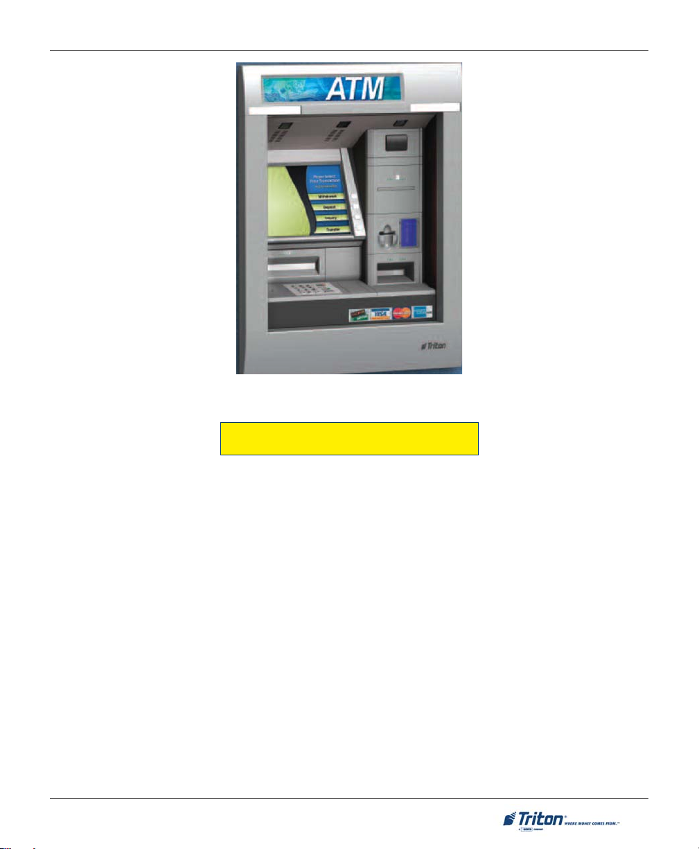
FT7000 (walk-up model)
STANDARD FEATURES
Standard features of the FT7000XP ATM are summarized in the following paragraphs.
ACCESS AND TRANSACTION SECURITY
Password-Controlled Access.
Access to the ATM’s Management Functions is protected by a password-based access scheme. The ATM
provides a “Master” password level of access and a flexible system of “User-level” passwords. The master
password provides full access to the ATM’s Management Functions, while User-level passwords provide
access to a subset of those functions, as determined by the holder of the master password.
Encrypting PIN Pad (EPP)
An Encrypting PIN Pad (EPP) is an encryption system that offers additional protection for the customer PIN
during entry at the ATM keypad. The EPP is compliant with all international encryption standards, Triple
DES, and Visa® requirements.
5
Page 16

MODEL FT7000XP USER MANUAL
MULTIMEDIA INTERFACE (AUDIO/VIDEO)
The ATM’s XGA color display can display text and graphical content in a wide range of colors, providing
an interesting and dynamic experience to the customer. In addition, graphics can be printed on receipts.
Supported multimedia features include: Receipt Graphics and Audio Output.
Receipt Printer Graphics
The thermal printer is capable of printing high resolution graphics when driven by appropriate software.
Like ad screen graphics, receipt graphics are usually downloaded to the terminal via the host processor.
Audio Output
The integrated speakers enhance the media experience by offering audio output of voice and/or music
content.
STORAGE OF FILES
The ATM can store management reports, such as the results of close operations or diagnostic tests.
Graphics files are stored and retrieved from the internal hard disk. You may also save reports to an external
memory device.
VOICE-ENABLED TRANSACTIONS
The ATM is capable of providing voice feedback to sight-impaired users, when configured and enabled. By
plugging a set of headphones into the integrated headphone jack, users can receive spoken assistance as
they perform a transaction.
COMMUNICATIONS
The FT7000XP supports communication with the transaction processor using a variety of communications
technologies. These include TCP/IP (standard) and SNA/SDLC lease line (optional).
TCP/IP (Ethernet)
This method is used in applications where a central Local Area Network, or LAN, is used to connect multiple
ATMs to a central server. The ATM can be treated as either a client or server on the network, while the host
provides the interface to a transaction processing system.
SNA/SDLC
Systems Network Architecture/Synchronous Data Link Control (SNA/SDLC) is IBM’s version of bit-oriented
protocol. SDLC is the link level protocol and SNA provides the intelligence for the connection. SNA and
SDLC use a series of commands to control the flow of data through the network
6
Page 17

INTRODUCTION
ELECTRONIC JOURNAL
The ATM stores transaction records, status, and other activity data in a journal record that is stored in the
ATM’s PC hard drive. The number of journal entries that can be stored is only limited by how much memory
is available on the hard drive.
This information can be retrieved at a later date. When needed, just the information desired can be recalled
and a printout of those records can be made. Journal entries may be viewed, printed, saved, and archived to
the terminal hard drive or to an external memory device.
TERMINAL SETTLEMENT
A suite of close functions are provided to facilitate daily balancing of the ATM’s internal record of transaction activity with the processor’s transaction records.
MULTI-LANGUAGE SUPPORT
The ATM has a screen language option. At the option of the financial institution, allows the terminal user
to select a preferred language (such as Spanish or French) to conduct a transaction (host .
MESSAGES
These are informational messages that give important information to the customer before, during, and after
a transaction. At the option of the financial institution, messages can be locally customized to meet local
requirements. They include greeting and exit messages, terminal owner and surcharge owner identification,
marketing messages, and news tickers.
TRANSACTION AND A CCOUNT TYPE CONFIGURATION
This feature (at the option of the financial institution) selects the types of transactions (transfers or balance
inquiries) or accounts (e.g. savings or credit card) that will be presented to the customer. This feature does
not affect the availability of checking account withdrawal transactions, which are always presented.
REAR SERVICE PANEL (RSP)
The RSP provides convenient user-access to most Management functions from inside the facility. It also
provides easy access to the dispensing mechanism, envelope depository unit, loading receipt paper, and
terminal shutdown.
7
Page 18
MODEL FT7000XP USER MANUAL
OPERATING SPECIFICATIONS / WEIGHT
snoitacificepSgnitarepO
erutarepmeT
ot0104)F(01ot05;)C(
)lanretxE(
)scinortcelE/tluaV(
)F(221ot03-;)C(05ot53-
ytidimuHevitaleR
noitpmusnoCrewoP
)xaM(
thgieW
sruoHssenisuB)solik454(sbl0001
1leveL)solik777(sbl0171
%08ot%02
gnisnednoc-non
zH06taCAV511@A0.6-0.4
zH05taCAV032@A0.4-0.2
)msinahcemettessac4htiw(
8
Page 19

SECTION 2
BASIC OPERATION
9
Page 20

MODEL FT7000XP USER MANUAL
INTRODUCTION
This section describes the basic operation of the terminal. The following topics are covered:
1. CONTROL PANEL LAYOUT. Describes the layout of the terminal’s control panel.
2. K
EYPAD OPERATION. Describes the use of the alphanumeric keypads.
CREEN FUNCTION KEYS. Describes the use of the screen keys.
3. S
4. REAR SERVICE PANEL. Provides easy access to Management function and diagnostics from inside
facility.
5. Rear Access Panels. Describes location of assemblies that may require daily interaction.
6. Front Control Panel. Easy access to customer interface components; ease of servicing.
7. MENU-BASED OPERATION. Provides a general overview of the terminal display interface.
8. ACCESSING MANAGEMENT FUNCTIONS. Describes the password entry procedure that must be followed
in order to access the Management Functions area.
9. VOICE-ENABLED TRANSACTIONS. Provides voice feedback via an integrated output jack, enabling sightimpaired users to plug in a set of headphones and receive spoken instructions to assist them in using
the ATM.
CONTROL PANEL LAYOUT
The user interface of the terminal consists of:
!!
! XGA COLOR DISPLAY (15.1 ")
!!
!!
! PRINTER RECEIPT CHUTE
!!
!!
! DIP CARD READER AND OPTIONAL MOTORIZED
!!
CARD
READER
!!
! ENVELOPE DEPOSITORY UNIT (OPTIONAL)
!!
!!
! DISPENSER SHUTTER
!!
!!
! HEADPHONE JACK (VISUALLY IMPAIRED)
!!
!!
! 24 KEYS ON THREE KEYPADS (MENU AND MAIN
!!
KEYPADS
10
)
Page 21
Function keys
Dispenser
shutter
Headphone
jack
BASIC OPERATION
Color display
Dip card
reader
Main keypad
Camera
window
Receipt chute
Motorized
card reader
(optional)
Envelope
depository
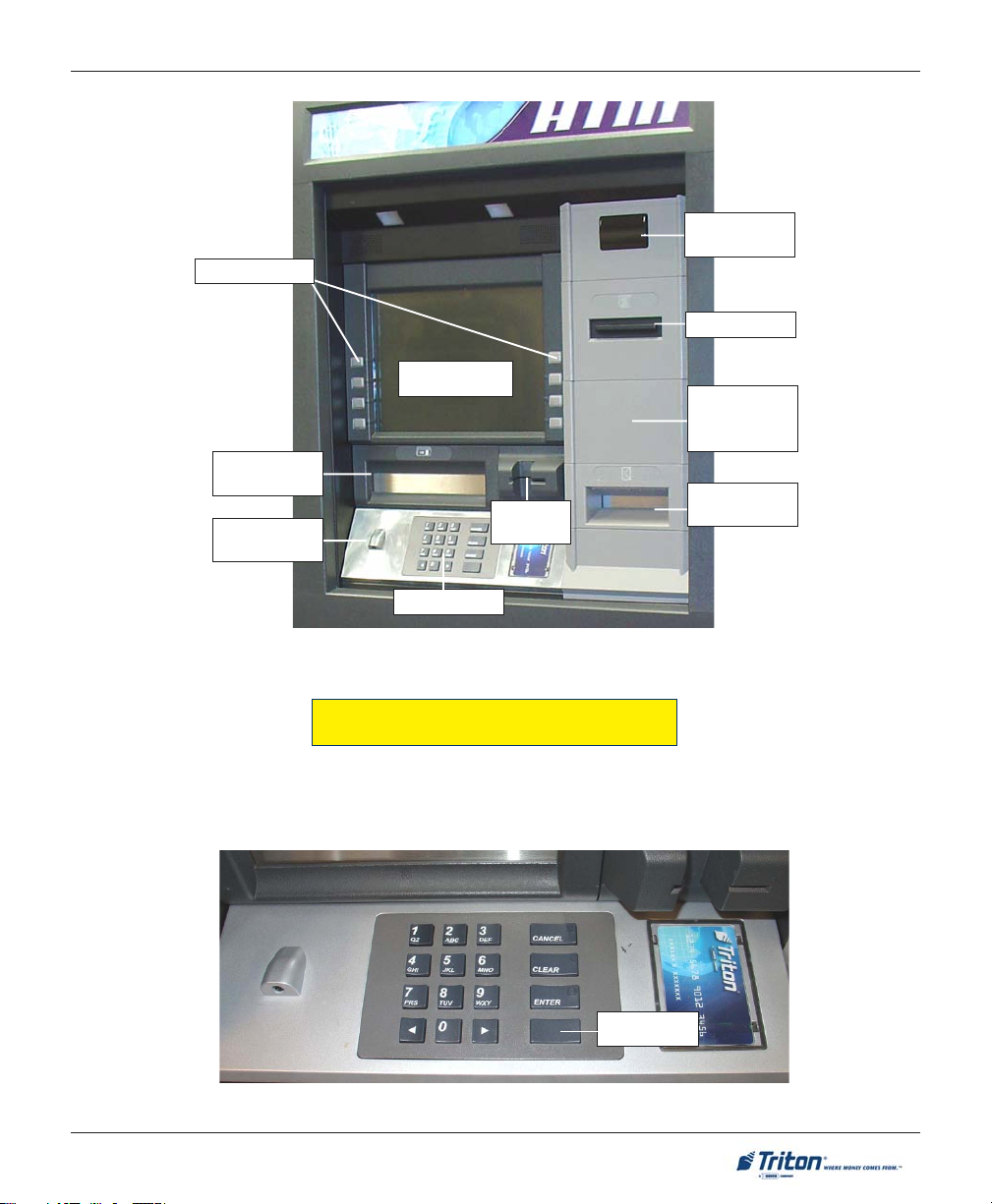
Figure 2-1. Control panel layout.
KEYPAD OPERATION
The main keypad consists of ten (10) alphanumeric keys, two (2) arrow keys and four (4) large control keys,
all located in a sixteen (16) key group beneath the LCD display. The keypad has integral raised Braille
symbols to conform to the requirements of the Americans with Disabilities Act.
CTRL key
Figure 2-2. Alphanumeric keypad.
11
Page 22
MODEL FT7000XP USER MANUAL
SCREEN FUNCTION KEYS
Refer to Figure 2-3. The eight (8) keys, four (4) on each side of the LCD, are called screen function keys.
They are used in the selection of screen options that can appear along the right and left side of the display.
These keys are designated F1 through F8. A screen function key is only active when a corresponding
function or menu option is present next to that key.
F1
F2
F3
F4
Figure 2-3. Screen function keys.
F5
F6
F7
F8
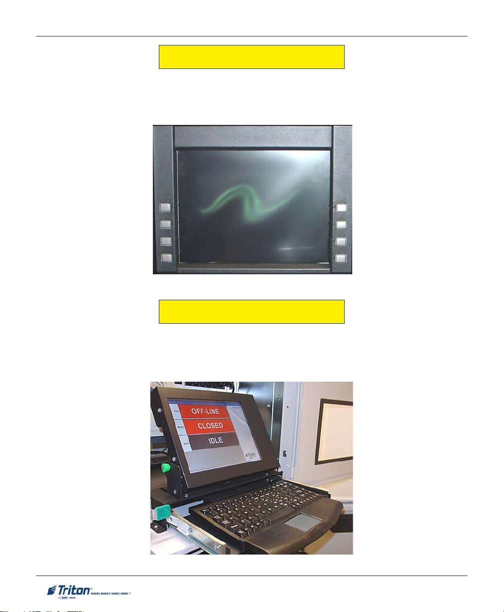
REAR SERVICE P ANEL
The Rear Service Panel (RSP) houses a 10.4" (264mm) SVGA color display with 800 x 600 resolution and a
slide-out keyboard with mouse pad. This provides convenient user-access to most Management functions
from inside the facility. The display pivots up when used or may lay flat allowing access to the terminal
power supply, computer, and Uninterrupted Power Supply (UPS) assemblies..
Figure 2-4. Rear service panel (Display / keyboard).
12
Page 23

BASIC OPERATION
REAR ACCESS SERVICE DOORS
The FT7000XP allows rear-access (inside facility) to most assemblies that may require daily attendance.
Replenishing currency cassettes, loading receipt paper/deposit envelopes and shutting power down to the
terminal are a few of the convenient task that can be performed.
Figure 2-5. Rear access doors.
FRONT A CCESS CONTROL PANEL
The front control panel (outside facility) provides
access to major electronic controlling devices (LCD,
keypad, shutter assembly). The release handle (located in rear access area) allows service technician
to open and rotate control panel for ease of maintenance.
Figure 2-6. Front control panel.
13
Page 24
MODEL FT7000XP USER MANUAL
MENU-BASED OPERATION
The terminal operates as a menu driven system. Messages and menu options presented on the LCD display
screen guide the user’s actions. The desired menu option is selected by pressing one of the screen keys
located to the left and right of the display. For the purpose of security, many screens timeout after a preset
time interval. The timeout length may vary depending on the function being performed.
When a screen timeout occurs, a screen is presented which asks the user if more time is needed. If the user
chooses NO, the Customer Welcome screen will be presented. If YES is chosen, the user is returned to the
function that was active prior to the timeout. If the user does not make a selection within an additional 30second countdown period the terminal will automatically go to the Customer Welcome screen.
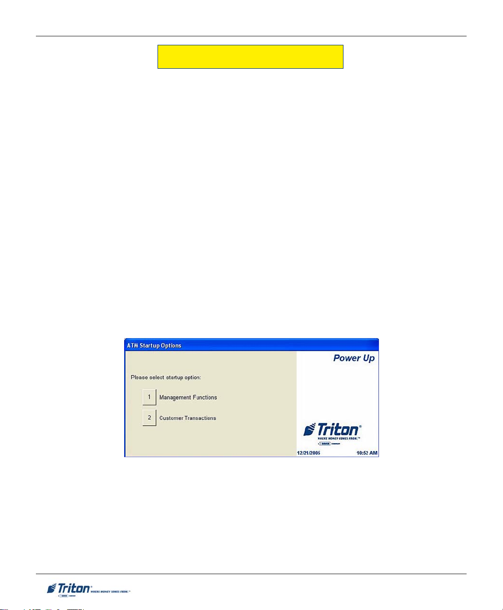
Shortly after the unit is turned on, the top menu will be displayed. An example top menu is shown in Figure
2-7. From the top menu, you can either:
" Activate the terminal to perform customer transactions by pressing the key next to Customer Transaction.
" Enter the terminal system management area by pressing the key next to Management Functions.
If you do not select a menu choice within 30 seconds the terminal will automatically default to the Customer
Welcome screen (a benefit of this feature is that in the event of a power interruption the terminal will
automatically begin accepting customer transactions shortly after power is restored).
Figure 2-7. Top menu.
14
Page 25
BASIC OPERATION
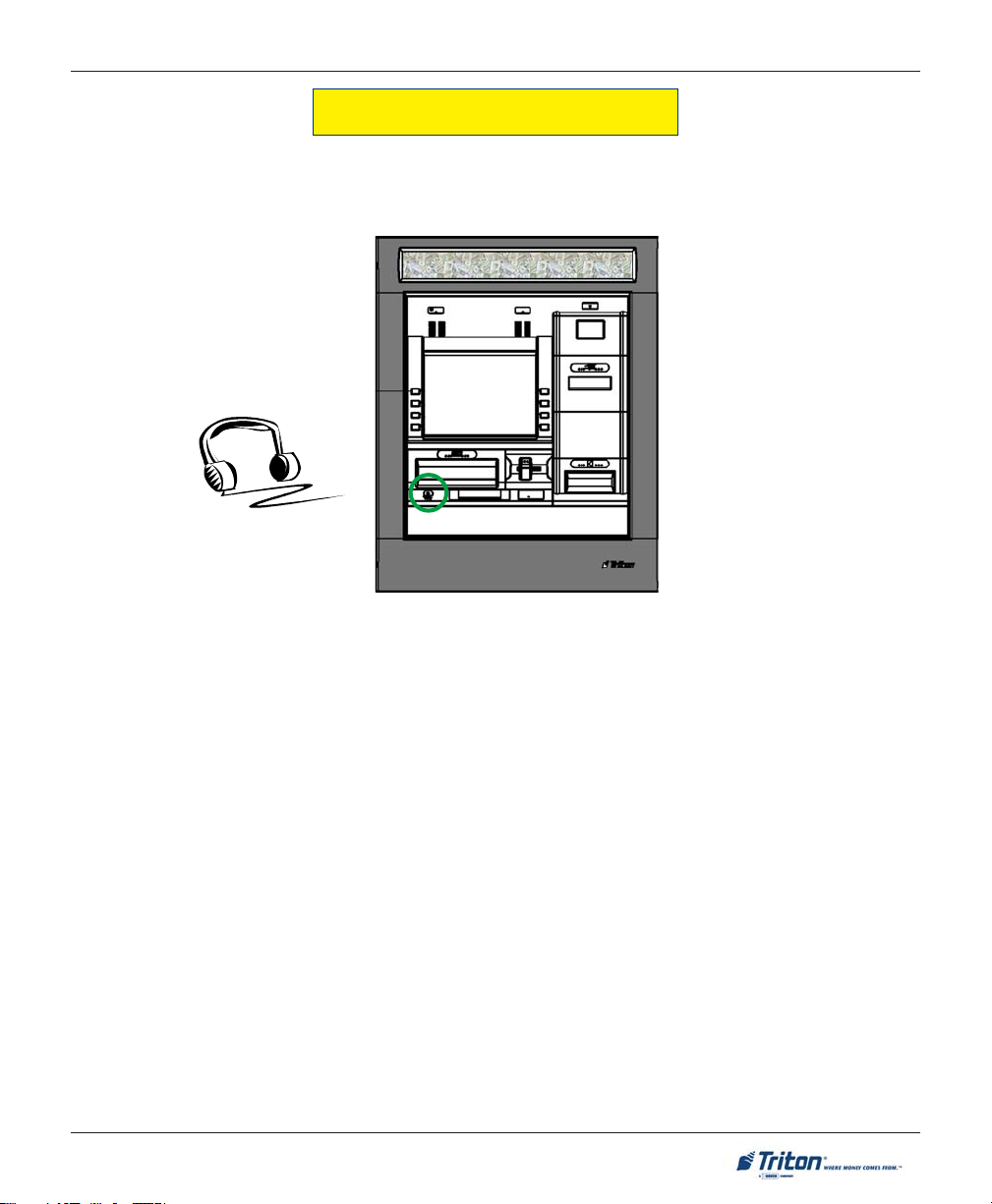
VOICE-ENABLED TRANSACTIONS
The terminal provides voice feedback via an integrated output jack, enabling sight-impaired users to plug
in a set of headphones and receive spoken instructions to assist them in using the ATM. Figure 2-8,
headphone jack location, shows the location of the headphone jack on the FT7000XP.
Figure 2-8. Headphone jack location.
Raised symbols helps a user locate the headphone jack. The ATM will automatically detect when a headphone has been plugged into the jack, and will immediately switch into voice mode. Initially, a brief spoken
tutorial will orientate the customer to the ATM control panel interface. Once the customer begins a transaction, spoken prompts will provide feedback and guide the customer through the successful accomplishment of the transaction.
15
Page 26

MODEL FT7000XP USER MANUAL
THIS PAGE INTENTIONALLY LEFT BLANK
16
Page 27
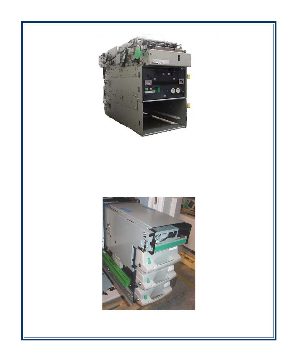
Fujitsu 510
SECTION 3
REPLENISHING CASSETTES
NMD-100
17
Page 28

MODEL FT7000XP USER MANUAL
INTRODUCTION
The purpose of this section of the manual is to describe the procedures for: (1) removing and replacing note
cassettes, (2) loading cassettes, and (3) removing and replacing the reject notes (as applicable). Information
concerning note handling and quality issues are explained where appropriate.
DISPENSING MECHANISMS
The FT7000XP ATM uses a Fujitsu® F510 friction-fed dispensing mechanism to store and deliver notes and
other media to the customer. This dispenser is standard in Business Hours and Level 1 units. An optional
NMD-100 is available in Level 1 units only. The mechanisms are located in the lower-right area of the
security container of the unit. It holds multiple cassettes and has an integrated reject bin.
FUJITSU F510: The note capacity for the Fujitsu cassettes is approximately 2250 (used). The maximum
number of notes that can be dispensed during a single transaction is forty (50). The dispenser holds
multiple cassettes (max 4) and has an integrated reject area.
NMD-100: The note capacity for the NMD-100 cassettes is approximately 2750 (used). The maximum
number of notes that can be dispensed during a single transaction is fifty (50). The dispenser holds multiple
cassettes (max 4) and has a dedicated reject cassette.
The dispensing mechanism delivers the appropriate number of notes from the note cassettes to fulfill the
customer’s withdrawal request. The purpose of the reject area/cassette is to accept and hold notes that
have been transferred from the note cassettes but not dispensed. Some situations that could cause the
mechanism to reject notes are:
! Multiple notes stuck together
! Note width too short or long
! Notes skewed in feed path
! Notes too close together in feed path
! Notes not claimed by customer
The mechanism(s) is able to reject single notes or bundles. A bundle reject occurs when more than one note
is rejected at the same time.
FUJITSU 510: The reject area is located in the first (1st) cassette (top). The reject compartment can hold
approximately 150 notes.
NMD-100: The reject cassette has two (2) compartments within the cassette. The top compartment can
hold 250 bundle notes; the lower compartment can hold up to 100 single-note rejects.
**CAUTION**
DO NOT RECYCLE REJECTED NOTES INTO A CASSETTE!
Doing so could cause more rejects and/or currency jams.
18
Page 29
REPLENISHING CASSETTES
NOTE CONDITION
The number of rejects can be directly influenced by the technique used to load the cassettes and the quality
of the currency. Notes loaded into the mechanism cassettes must be in “fit” condition if a high level of
performance (low reject and failure rate) is expected from the unit. “Fit” notes are defined as those that do
not possess any of the defects listed here:
USED NOTE D EFECTS
! Adhesive or “sticky” substances on the surface of the paper.
! Tears extending more than 1/2” from the edge of the currency.
! Tears, holes, or missing sections in the body of the currency.
! Tape on the surface of the currency used for repairing, patching or any other purpose.
! Staples, pins, or any other foreign body attached to the notes.
! Corner folds of a size greater than 1/2” on either axis.
! Two or more notes joined by any means.
! Excessively crumpled or crinkled.
PREPARING NOTES
Use the following procedures to prepare notes before inserting them into a note cassette.
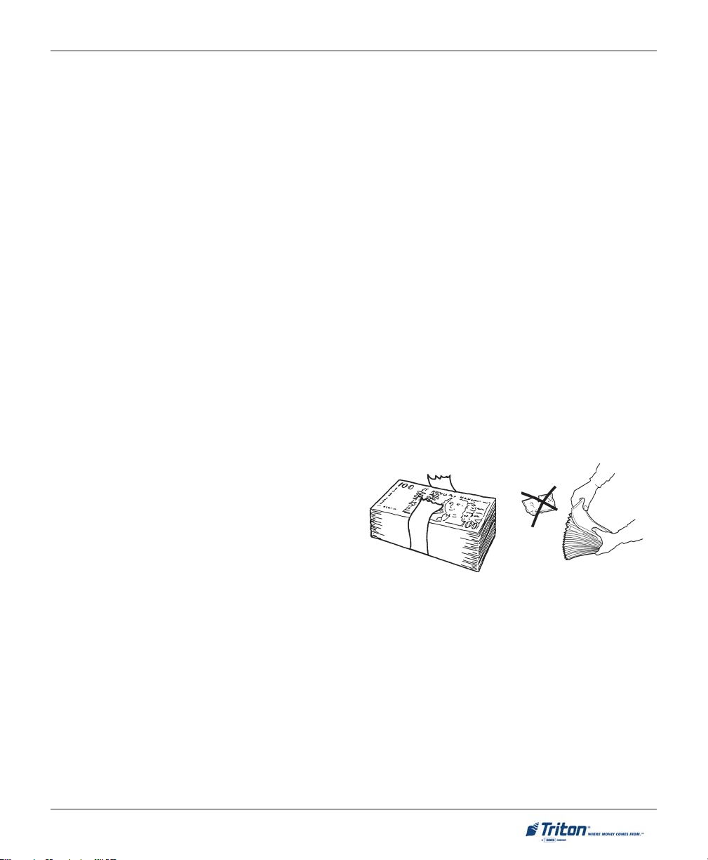
PREPARING USED NOTES
! Remove the band around each bundle of notes.
! Remove foreign objects (e.g. pins, paper clips, crumbs,
etc.).
! Remove torn or very worn notes.
! Straighten any folded notes.
NEW OR UNCIRCULATED NOTES
Remove the band around each bundle of notes. Separate the notes from each other by:
! !
! Striking the bundle hard against the edge of a table or similar object.
! !
! !
! Flipping through each bundle of notes in both directions at each end.
! !
Figure 3-1. Removing
band.
Figure 3-2. Removing
torn/worn notes.
! Using a note counter.
19
Page 30
MODEL FT7000XP USER MANUAL
REPLENISHING CASSETTE(S) - F510
To perform a cash replenishment, enter Management Functions > Terminal Settlement Functions > Replenish Cassette(s). Follow the prompts to replenish cassette(s).
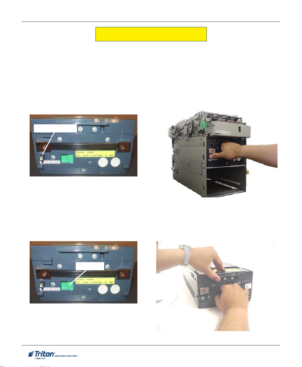
REMOVING NOTE CASSETTE:
1. Open the electronic lock on the security container door to gain access to the dispensing mechanism.
2. To remove the selected note cassette, grasp the cassette handle and push the green release button .
Pull the cassette out slightly. Place one hand underneath to support the cassette as you slide it
completely out of the unit.
Release button
Figure 3-3. Release button.
Figure 3-4. Pull note cassette.
OPENING NOTE CASSETTE:
1. Place the cassette on a table or other flat surface. Open the cassette by sliding the green latch lever to
the right and lifting the lid.
Lid latch
Figure 3-5. Latch lever.
Figure 3-6. Open cassette.
20
Page 31

REPLENISHING CASSETTES
2. Flip the lid back fully. Hold the green knob and pull the pressure plate to the rear (toward the handle).
Release the knob and ensure the plate is caught.
Figure 3-7. Move pressure plate to rear.
Figure 3-8. Plate latched to rear.
LOADING / INSTALLING NOTE CASSETTE:
1. Remove any rejected notes from the reject area. Note: Only the TOP cassette accepts rejects.
! Before loading the cassette with currency:
The shape of some notes may be affected by conditions of storage or bundling, preventing them from
forming neat even piles. If not corrected, such conditions may cause notes to be rejected by the
dispensing mechanism. To compensate for the most common conditions of slanting or cupped note
piles, follow the directions given here. Notes with no apparent shape problems are referred to as
“common” notes.
• Slanting pile
To avoid dispensing problems caused by a “slanting” pile, put the notes in neat bundles of no more than ½
to ¾ inches in thickness. Turn every other bundle around to minimize slanting of the pile.
• Cupped bundle
To avoid dispensing problems caused by cupped bundles, turn all the bundles with the cupped side
towards the dispense opening.
• Common notes
Place the prepared bundles in the cassette.
21
Page 32

MODEL FT7000XP USER MANUAL
2. Align the notes and load them in the cassette. Level the note pile. Compress the note pile slightly by
hand. Single notes must not protrude from the bundle.
3. Move the pusher plate against the notes with just enough pressure to hold the notes in the correct
position.
Figure 3-9. Align/level note pile. Figure 3-10. Move pressure plate against notes.
4. Fold the cassette lid down to its locked position. Insert the cassette back into the mechanism. Ensure
the cassette is pushed all the way back in the cassette channel.
Figure 3-11. Insert cassette back fully
into dispenser.
* IMPORTANT *
BEFORE INSERTING CASSETTES IN THE FEED CHAN-
NELS, ENSURE THE OPEN/CLOSE TAB ( LOCATED IN
EACH
CHANNEL) IS IN THE “CLOSE” POSITION. THE
TAB
SHOULD BE IN THE POSITION SHOWN BELOW. IF
NOT
, BILL FEED ERRORS WILL OCCUR!
Figure 3-12. Open / Closed tabs.
22
Page 33

REPLENISHING CASSETTES
REPLENISHING CASSETTE(S) - NMD-100
To perform a cash replenishment, enter Management Functions > Terminal Settlement Functions > Replenish Cassette(s). Follow the prompts to replenish cassette(s).
R
EMOVING NOTE CASSETTE:
1. Open the lower right rear cabinet door (2-door) or lower cabinet door (1-door).
2. To remove the selected note cassette, grasp the cassette handle with one hand while holding the
mechanism in place with the other hand (Figures 3-13 and 3-14). Pull the cassette out slightly. Place one
hand underneath to support the cassette as you slide it completely out of the unit.
Figure 3-12. Cassette removal.
3. Continue to support the bottom of the cassette to
keep it level as you place it on a table or other flat
surface. If the cassette has a loading arm, fold it
down, which will raise the rear of the cassette and
allow gravity to help keep the notes neatly stacked
during the loading process (Figure 3-15).
23
Figure 3-13. Cassette removal.
Figure 3-15. Note cassette.
Page 34

MODEL FT7000XP USER MANUAL
OPENING NOTE C ASSETTES:
1. Insert the key into the cassette lock (Figure 3-16). To unlock the cassette, apply inward pressure on the
key while turning it clockwise to the stop position (approximately a quarter-turn). Open the cassette by
simultaneously pressing the release button and lifting the lid. Flip the lid back fully, allowing it to rest
on the table or other flat surface (Figure 3-17).
Figure 3-16. Key inserted.
2. Move the pusher plate to the rear of the cassette
(toward the handle). Ensure the pusher plate is
fully back. It should stay in this position (Figure 3-
18).
Figure 3-18. Open lid and move pusher plate back.
Figure 3-17. Release button.
LOADING NOTE CASSETTES:
1. Load the cassette with currency. The shape of some notes may be affected by conditions of storage or
bundling, preventing them from forming neat even piles. If not corrected, such conditions may cause
notes to be rejected by the dispensing mechanism. To compensate for the most common conditions of
slanting or cupped note piles, follow the directions given here. Notes with no apparent shape problems
are referred to as “common” notes.
24
Page 35

REPLENISHING CASSETTES
• Slanting pile
To avoid dispensing problems caused by a “slanting” pile, put the notes in neat bundles of no more
than ½ to ¾ inches in thickness. Turn every other
bundle around to minimize slanting of the pile.
• Common notes
Place the prepared bundles in the cassette.
2. Level the note pile. Compress the note pile slightly by hand. Single notes must not protrude from the
bundle (Figure 3-19).
3. Move the pusher plate against the notes with just enough pressure to hold the notes in the correct
position when closing the lid and inserting the cassette into the mechanism (Figure 3-20).
• Cupped bundle
To avoid dispensing problems caused by cupped
bundles, turn all the bundles with the cupped side
towards the dispense opening.
Figure 3-19. Leveling note pile.
4. Move the white plastic levers (Pawls) on the pusher plate to their fully extended position. This will
allow the pusher plate to retract and release pressure from the note stack when an unlock command
is sent to the dispenser (Figure 3-21).
Figure 3-21. “Pawls” extended.
5. Close the cassette lid. Fold the lid down to its locked position. The release button should “pop” out,
allowing the lid to mate cleanly with the body of the cassette. You may need to “tap” the lid firmly along
the front edge to achieve this. Turn the key counterclockwise to lock the cassette.
Figure 3-20. Moving pusher plate against notes.
25
Page 36

MODEL FT7000XP USER MANUAL
INSTALLING NOTE CASSETTE:
Using the reverse of the steps used to remove the note cassette from the mechanism, slide the note cassette
into its slot in the mechanism. Keep the cassette level as you load it, and make sure the cassette is fully
inserted. Once all cassettes have been filled and reinserted, they are ready to be <Locked> into position
following the Replenish Cassette(s) function prompts.
* NOTE *
Before locking cassettes, it is recommended to check the Reject Cassette for
any rejected notes. The procedures for the reject cassette are described next.
REMOVING THE REJECT CASSETTE:
*IMPORTANT*
If you remove the reject cassette with power applied, the terminal
will sense this and automatically reset the rejected note count to
ZERO. Therefore, to ensure an accurate rejected note count NEVER
REMOVE THE REJECT VAULT WITH POWER APPLIED WITHOUT CHECKING FOR AND REMOVING ANY REJECTED NOTES!
1. Ensure cassettes are <Unlocked>. To remove the reject cassette, (top channel) grasp the cassette
handle with one hand while holding the mechanism in place with the other hand. Pull the cassette out
slightly. Place one hand underneath to support the cassette as you slide it completely out of the unit.
Place it on a level surface (Figures 3-22 and 3-23).
Figure 3-22. Removing the reject vault.
Figure 3-23. Reject vault ready to open.
26
Page 37

REPLENISHING CASSETTES
OPENING THE REJECT CASSETTE:
1. Insert the key into the cassette lock. To unlock the cassette, apply inward pressure on the key while
turning it clockwise to the stop position (approximately a quarter-turn). Open the cassette by simultaneously pressing the release button and lifting the lid. Flip the lid back fully (Figures 3-24 and 3-25).
Figure 3-24. Key inserted. Figure 3-25. Opening lid.
2. The reject cassette is now open for collecting any rejected bundle notes. These will be present in the
folding tray. After retrieving any rejected bundle notes, lift the folding tray and check underneath for
any rejected single notes (Figures 3-26 and 3-27).
3. After removing any rejected notes, close the lid. Fold the lid down to its locked position. The release
button should “pop” out, allowing the lid to mate cleanly with the body of the cassette. Turn the key
counterclockwise to lock the cassette.
Figure 3-26. Bundle reject tray.
Figure 3-27. Single reject compartment.
INSTALLING THE R EJECT CASSETTE:
Using the reverse of the steps taken to remove the reject cassette, slide the cassette back into its slot in the
mechanism. Make sure the cassette is fully inserted. Following the Replenish Cassette(s) function prompts,
<Lock> all cassettes.
27
Page 38

MODEL FT7000XP USER MANUAL
VERIFY OPERATION
1. NMD-100 only. Verify the cassettes are <Locked> in the dispenser.
2. In Management Functions, select DIAGNOSTICS, then CASH DISPENSER.
3. Select the TEST DISPENSE option. Enter # of notes to be dispensed (1-5) from the individual cassettes
that are installed (“A”, “B”, “C”,or “D”). Select PERFORM TEST. The Test Dispense operation will start.
Figure 3-28. Enter # of notes.
4. The Test Dispense command instructs the dispenser to dispense, minimum, one note from each
installed and operational cassette into the reject cassette. This test exercises the dispenser without
sending notes to the exit.
5. After completion of the Test Dispense, the following prompt is displayed (Figure 3-29).
Figure 3-29. Test dispense prompt.
28
Page 39

Receipt Printer
SECTION 4
GENERAL MAINTENANCE
Envelope Depository Unit
29
Page 40

MODEL FT7000XP USER MANUAL
INTRODUCTION
This section of the manual covers general preventive and corrective maintenance procedures appropriate
for user personnel. The following areas are covered:
1. R
EPLENISHING RECEIPT PRINTER. Describes how to replace a spent receipt paper roll.
2. LOADING ENVELOPES / REPLACING RIBBON CARTRIDGE IN ENVELOPE DEPOSITORY. Describes how to load
envelopes and replace ribbon cartridge in the envelope depository unit.
EPLENISHING PAPER (JOURNAL PRINTER). Describes how to replace the spent journal paper roll.
3. R
4. LOADING INK CARTRIDGE (JOURNAL PRINTER). Describes how to load the printer ink cartridge.
5. CLEANING THE ENCLOSURE. The proper way to clean the ATM housing and displays..
6. CARD READER CLEANING. The recommended card reader cleaning technique.
7. RECEIPT PAPER SPECIFICATIONS.
REPLENISHING RECEIPT PAPER
NOTE: This operation must be completed with power applied to the ATM.
1. Open the top left rear cabinet door.
2. Pull up on the tray locking pin and extend printer tray fully. If paper remains on the roll, cut the paper
between the roll and the input to the printer with a pair of scissors.
Figure 4-1. Printer tray extended. Figure 4-2. Cut paper roll.
30
Page 41

GENERAL MAINTENANCE
3. Push the FEED button up (located on Printer controller module) to advance the paper remaining in the
feed path.
4. Remove the existing paper roll and/or empty spindle (as appropriate) from the paper support bracket.
Paper Insertion Guide
Figure 4-4. Paper/spindle removed.
Reset
Feed
Figure 4-3. Printer controller module.
** CAUTION **
Do not pull the paper backward through the
printer. This may leave paper fragments that
can cause paper jams.
5. Unwind about 18 inches from the end of the new
roll of paper. Using scissors, cut off the excess.
Make sure all the paper that has glue on it is
removed from the end of the roll.
6. Install the new paper roll on the spindle. Place
the paper roll (w/spindle) on the paper support
bracket by sliding ends of spindle into the
bracket.
NOTE: THE PAPER FEEDS FROM THE
BOTTOM OF THE ROLL!
Reverse
Figure 4-5. Paper roll/spindle.
Figure 4-6. Printer controller module.
31
Page 42
MODEL FT7000XP USER MANUAL
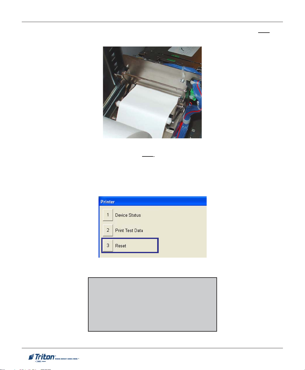
7. Refer to the paper insertion guide located in Figure 4-3. Pass the end of the paper roll over the
tension roller and insert into the take-up slot. The printer will automatically grab the paper.
Figure 4-7. Insert end of paper into slot.
Paper passes over the tension roller.
8. FROM REAR SERVICE PANEL - Enter MANAGEMENT FUNCTIONS main menu. Select DIAGNOSTICS >
PRINTER. Choose option <3>, RESET. The printer will reset and display a status report. Select
<PRINT>. The report will print to the receipt printer. The printer is now in the Ready state.
9. Push printer tray back into the cabinet. Ensure the locking pin engages.
*IMPORTANT*
Only qualified service personnel are authorized
to repair or service the terminal. Should a malfunction occur, DO NOT attempt to service the
unit yourself! Contact your Triton certified service provider!
32
Page 43
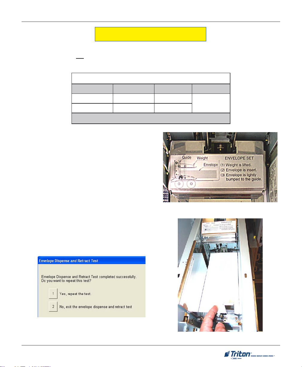
GENERAL MAINTENANCE
LOADING ENVELOPES (EDU)
The Envelope Supply Unit holds approximately 200 envelopes. When loading envelopes, alternate every
50-100 with the flaps UP. For example, load 50 with flaps up facing Left, then next 50 with flaps up facing
Right. The envelope size requirements are as follows:
tnemeriuqeReziSepolevnE
s
htgneL htdiW ssenkcihT
muminiM]"19.5[mm051]"57.3[mm59
mumixaM]"6.9[mm442]"52.4[mm801
1. Open the upper left rear cabinet door and pull the
Envelope Depository Unit slide tray out fully.
2. Following the instructions on inserting envelopes
(label on unit), load envelopes (flap up into the
supply bin.
NOTE: Remember to alternate envelopes
approximately every 50 with the flaps facing leftright.
Slide tray back into the cabinet.
Figure 4-8. Envelope load label.
3. Access Management functions and from the Main
menu screen select Diagnostics > Envelope Depository
> Envelope Dispense and Retract Test. The test
dispenses an envelope and then automatically retracts
it into the depository storage bin (normal operation).
]"72.[mm7
)mm1.832xmm8.401(epolevne01#asiezisdednemmoceR:etoN
4. After the test is complete, press <2> to exit.
Figure 4-9. Load envelopes flap-up.
33
Page 44

MODEL FT7000XP USER MANUAL
REPLACING RIBBON CARTRIDGE (EDU)
The depository accepts an envelope, monitors its progress through the unit, stamps it with identifying data
(up to 68 characters with the Dot Matrix Printer), and deposits the envelope in the envelope deposit bin.
Figure 4-10. Location of ribbon cartridge.
1. Remove ribbon cartridge from the four (4) plastic tabs that hold it.
2. Mount the new ribbon cartridge into the printert holder as shown below. Ensure cartridge aligns with
the plastic tabs.
3. Confirm that the ribbon is positioned between the mask and head, then turn the ribbon knob in a
clockwise direction until taut.
Figure 4-11. Install ribbon cartridge.
Figure 4-12. Turn knob to tighten ribbon.
34
Page 45

GENERAL MAINTENANCE
REPLENISHING PAPER (JOURNAL PRINTER)
*** Warning ***
Remove power from the terminal during any servicing that requires the
user to insert fingers into the printer wheel area.
NOTE: The following steps reference Figure 4-13 and 4-14.
Cut / Feed
switch
Bail
Bail slot
Figure 4-13. Journal printer.
Steps 1 through 9 reference Figure 4-14:
1. Lift the Bail (item 3) and remove any paper that may be inside the printer. Close the Bail.
2. Place the paper roll (item 4) in the Paper Handler (item 5). The paper roll must have a roll pin through its
center.
Paper “out’
sensor
35
Page 46

MODEL FT7000XP USER MANUAL
Figure 4-14. Loading journal paper.
3. Direct the paper (item 6) from the paper roll (item 4) through the Paper Out Sensor and down into the
Guide slot (item 7) until the paper stops against the Feed Mechanism (item 8). Remove the Journal Takeup Carriage (item 9).
4. The paper is now ready to be advanced automatically through the rest of the printer assembly. First,
turn the power switch ON. After a few seconds, press the Feed Switch until the Feed Mechanism (item
8) passes approximately 5-7 inches of paper beyond the Bail (item 3). You may need to apply hand
pressure on the paper, directed towards the Feed Mechanism (item 8), in order to activate the Feed
Mechanism (item 8).
5. Lift the Bail (item 3) and pull the journal paper (item 6) out of the Bail Slot (item 10).
6. Guide the journal paper (item 11) through the Journal Slot (item 12). Attach the leading edge to the clip
on the Journal Take-up carriage (item 9).
Steps 7 and 8 redirect the journal paper to the Journal Take-up carriage.
7. Advance the Journal Take-up Carriage (item 9) by hand until the journal paper (item 11) is taut.
8. Attach the Journal Take-up Carriage (item 9) to its mounting bracket.
9. The journal paper is now loaded.
36
Page 47

GENERAL MAINTENANCE
LOADING INK CARTRIDGE (JOURNAL PRINTER)
NOTE: The following steps reference Figures 4-15
through 4-18.
*** Warning ***
Remove power from the terminal
during any servicing that requires
the user to insert fingers into the
printer wheel area.
Cut / Feed
switch
Bail
Bail slot
Figure 4-15. Journal printer.
1. If there is a used ink cartridge already loaded, remove it by opening the Bail and pulling the cartridge
directly off the Drive shaft (Figure 4-16).
Bail
(Closed position)
Drive shaft
Paper “out’
sensor
Figure 4-16. Front view of ink cartridge area.
37
Page 48

MODEL FT7000XP USER MANUAL
2. Before inserting the new ink cartridge, turn the cartridge knob “counterclockwise” until ribbon is taut
(Figure 4-17).
3. Open the Bail. Carefully mount the ink cartridge onto the drive shaft, keeping the ribbon between the
Platen and the Printhead (Figure 4-18).
Knob
Figure 4-17. Turn knob counterclockwise.
4. Thread the ribbon through the Guide slot and, before closing the Bail, make sure the ribbon is still taut
by turning the cartridge knob counterclockwise (Figure 4-18).
5. Close the Bail. The ink cartridge is now loaded.
Bail
(Open position)
Ink cartridge
Platen
Guide slot
Printhead
Cartridge knob
Figure 4-18. Ink cartridge installed.
38
Ribbon
Page 49

GENERAL MAINTENANCE
CLEANING THE E NCLOSURE
The ATM front panel/trim is highly durable, resisting scratches and finger smudges. However, occasional
cleaning of the front panel and the plastic enclosure may be desirable. A soft dry or slightly damp cloth may
be used for cleaning. For best results, use a weak solution of a mild detergent and water.
** CAUTION **
Avoid using abrasive cleaners on
any surface of the terminal. Do
not spray liquid cleaner directly
on the unit.
CLEANING THE D ISPLAY
The Liquid Crystal Display (LCD) on the front of the ATM has a glass protective shield that should be
cleaned only with a soft lint free cloth, dampened with a weak solution of a mild detergent and water.
** CAUTION **
Do not use any abrasive cleaners
on the window, as it will scratch.
Do not spray liquids onto the
screen, as they may run down inside the unit and cause damage.
CARD READER CLEANING
Special cleaning cards (P/N 06200-00055) are available for proper maintenance of the card reader. The reader
should be cleaned at least once a month by inserting and removing a cleaning card as shown below. It may
be necessary to clean the card reader more often in locations that see heavy usage.
1. Remove the cleaning card from the sealed pouch.
2. Insert the cleaning card into the card reader and move in and out
several times.
3. Remove the cleaning card and turn over to use other side.
4. Insert again several times.
5. Remove cleaning card and discard.
39
Page 50

MODEL FT7000XP USER MANUAL
RECEIPT PAPER S PECIFICATIONS
P
APERSPECIFICATI ONS
noitpircseD noisnemiD eulaV
htgneLtpieceRAmm8.771otmm9.88)"0.7ot"5.3(
htdiWtpieceRB+0.08/mm0- +"51.3(mm1"0-/)"10.0
htdiWkramesneSC nim)"53.0(mm0.9
thgieHkramesneSD
ytivitcelfeRecafruSkramesneS-
retemaiDlloRrepaPE
ssenkcihTllaWeroCF nim)"791.0(mm0.5
)DI(retemaiDedisnIeroCG )"210.0-/+"0.1(mm3.0-/+4.52
lairetaMeroC-
kcotSrepaplamrehT
deificepsnahtrehtorepapgnisU(
)ytilauqtnirptceffayam
-
wolebdna%4
xam)"0.01(mm0.452
repaPtfarK
* NOTE *
The FT7000 Receipt printer
does not require sense marks.
)"210.0-/+"791.0(mm3.0-/+0.5
Sense marks are supported for
)mn0001-mn007neewteB(
proper alignmenrt of preprinted text and graphics.
The unavailable pre-print area
is for sense mark paper only!
)snorcim4-/+16(053-P:ikaznaK
)snorcim5-/+26(054DP:ijOro
40
Page 51

SECTION 5
MANAGEMENT FUNCTIONS
41
Page 52

MODEL FT7000 USER MANUAL
INTRODUCTION
This section describes the Management Functions available running Prism 912 emulation controlling the
ATM.
WHAT IS P RISM 912-EMULATION
Prism offers true, open-ended, object-oriented architecture using industry standard Microsoft® development
tools. The unique software design and integrated Web browser enables Prism to be plug compatible with
existing ATM processor networks without changes to the existing host system. The Prism application can
operate in an ATM network, alongside standard OS/2-based ATMs, without any host changes. But it is
more than a standalone application. Prism application is also flexible and can be customized at all levels.
Prism liberates ATM content from the rigid and expensive development requirements of proprietary systems.
Specialty services, advertising and cross selling are easy to implement with Prism, allowing FI’s to extend
the same brand differentiation used in branches and on FI’s Web site to the ATM channel. The following
summarizes the features and benefits of the Prism application:
SEAMLESS INTEGRATION
· Prism is ‘plug-and-play’ in today’s 912 ATM network - without changes to existing host download
and ATM infrastructure
· Provides concurrent support of legacy 912 transactions and content from a web-server without
host changes.
· Compatible with all major ATM Protocols – TCP/IP and SNA/SDLC communications.
· All application software is industry standard MS Windows compliant with CEN-XFS universal
standards.
· Prism permits the financial institutions to implement web technology without any disruption to
existing ATM operations or back-end changes.
INVESTMENT PROTECTION
· Prism (under Fujitsu) was certified on all major ATM networks in North America
· Prism is transparent to the ATM driving platform and easily transportable to a new host ATM
device driver without any re-programming or vendor intervention.
· Fully preserves the financial institution’s investment in technology.
• Prism allows the FI to convert 912 screens into HTML format preventing any additional resource
burden or vendors’ Professional Services intervention.
· Prism is multi-vendor capable.
42
Page 53

MANAGEMENT FUNCTIONS
WHAT IS MEANT BY A “WINDOWS-BASED” ATM?
The current ATM environment is still one that is largely driven in a Diebold® or NCR® emulation environment
that uses traditional “states and screens” – command sets. The host processor sends “states and screens”
to the ATM and which the ATM uses to build transaction requests and display content to its user. With
that in mind, we define a “Windows driven” ATM as one which runs on the Microsoft® Windows® XP
operating system platform; communicates using the TCP/IP communications protocol, or a combination of
TCP/IP and another protocol such as SNA when used in conjunction with a legacy transaction processing
emulation such as 912; takes advantage of Web technologies, including an industry standard browser
(Internet Explorer) and HTML Web page and development tools which, used together, accurately represent
as well as enhance the current states and screens methodology; is powered by an underlying ATM software
application such as Prism that builds a new, content-rich HTML-based graphical user interface.
Working together, these characteristics enable new types of enhanced services that lower cost, increase
brand reach, extend online banking capabilities and grow new revenue streams. It is important to keep in
mind, however, that while Web-enabled ATMs deploy Web technologies, they are neither designed nor
intended for use as a Web surfing device.
WHAT DIFFERENTIATES THE WINDOWS-BASED ATM FROM ITS PREDECESSOR?
Windows based ATMs are the new generation of ATMs that are broadly distinct from their predecessors in
the technology they use and the business benefits they can deliver.
In an increasingly competitive retail banking market, OS/2 based ATMs no longer meet the changing
competitive and regulatory requirements that challenge today’s financial institutions. Windows-based
ATMs promise to dramatically alter the role of ATMs in the delivery of banking products and services, and
ultimately in the relationship between financial institutions and their ATM customers.
43
Page 54

MODEL FT7000XP USER MANUAL
XP PRISM SOFTWARE A RCHITECTURE
The above diagram is a high level overview of the Triton ATM software architecture running Prism. The
base operating system is Windows XP Pro and at the low end you have hardware devices with their
firmware that communicate to the WOSA middleware developed by KAL. Prism application conforms to
WOSA-XFS standards. WOSA-XFS allows higher-level applications to communicate with low-level device drivers. The Triton ATM WOSA-XFS compliant application is developed by KAL. Almost all other
ATM vendors in the industry use KAL middleware for their application. On top of that we have the Prism
application to perform 912 emulation and Web transactions. At the core of all this is the Internet Explorer
browser that is used to display all screen content in HTML format. The same browser is also used to
display host download text data to the consumer. This is where Prism application integrates both legacy
912 transactions and web-based transactions into a single screen format that is completely transparent to
the end user. This enables FI’s to modify the look and feel of the host transaction screens with engaging
HTML screens.
The 912-emulation defines the format of the messages exchanges between an ATM and the host processor
for processing consumer financial transactions. Prism 912-emulation is based on Diebold® iSeries 912
message standard. Prism conforms to 912 message standards for:
- Screens and States downloads
- Support all Screen 912 screen display functions
- 912 operational and message commands, and status messages
- Support 912 state types
For those FI’s that deploy a Triton ATM with Prism application, there will be no changes required to support
912, provided the FI currently has 912-emulation software running at the host end. It will be a “plug-andplay” implementation.
44
- Operational commands
- Function commands
- Full transaction support
- Withdrawal, deposit, balance inquiry…etc
Page 55
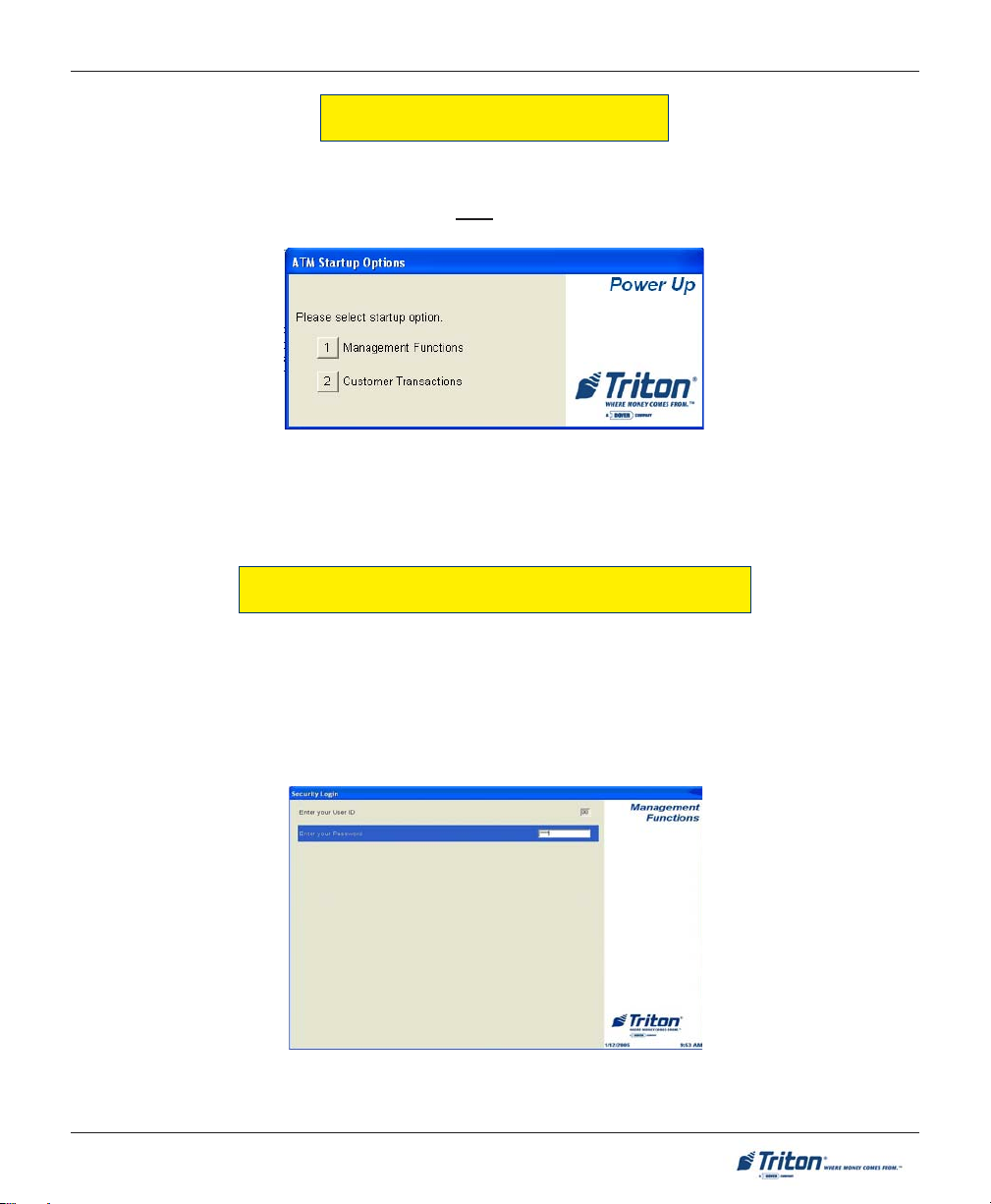
MANAGEMENT FUNCTIONS
DISPLAY POWER-UP SEQUENCE
When the ATM is powered on, or has been re-booted, “Out of Service” is displayed on the front screen.
The rear screen will display the “ATM Status” screen. After the power-up sequence is complete, the “ATM
Startup Options” screen will be displayed on the rear LCD - the front LCD will display the “Out of Service”
screen.
Figure 5-1. Start-up menu displayed on rear LCD .
The user selects the desired function by pressing either number <1> for Management Functions or number
<2> for Customer Transactions.
ACCESSING THE MANAGEMENT FUNCTIONS M ENU
When the Customer Welcome screen is displayed, you can access the Management Functions menu by
following the procedure described next.
! Press and hold down the blank <CTRL> key; while holding down the <CTRL> key, press the <1> key.
Release both keys. After a moment the “Security Login” screen will be displayed.
Figure 5-2. Security login screen.
45
Page 56

MODEL FT7000XP USER MANUAL
You must enter an appropriate password in the dialog box that appears when the Management Functions
option is selected. The password will consist of a 2-digit ID code and a password of 4-12 digits; for example,
051234 could be a password entry consisting of an ID code of 05 and a password of 1234.
! Enter the 2-digit ID code, then press <Enter>.
! Enter your password and press <Enter> again.
Figure 5-2. Enter your Master or User password.
DEFAULT MASTER PASSWORD
The default master user ID is “00” and the password is “1234”. Note: The Master User ID
is always ‘00’ and can not be changed! To enter Management Functions as the Master
user, enter:
“00” and “1234”
CHANGE THE MASTER PASSWORD (“1234”) IMMEDIATELY TO PREVENT UNAUTHORIZED ACCESS TO THE ATM!
When a valid login is entered, the Main Menu screen will be displayed (Figure 5-3).
Figure 5-3. Main menu screen.
46
Page 57

MANAGEMENT FUNCTIONS
SWITCHING SCREENS
The FT7000XP has two (2) displays - the front (Customer side) and rear (Operator service side). You can
access all menu options in the Management functions from the front display. When accessing Management functions from the rear display, certain options ( Key Management) will need to be configured from the
front display. You will be prompted to switch screens when this occurs (Figure 5-4).
Figure 5-4. Switch screen prompt.
Select the <CTRL> button and the following screen will appear (Figure 5-5). Press number <3> to switch
display access. You will again see the “Security Login”. Enter your ID code and password to access Management functions.
Figure 5-5. Control key menu screen.
47
Page 58

MODEL FT7000XP USER MANUAL
FUNCTION A VAILABILITY
Once you have entered the Main Menu, you may perform any of the functions allowed by the type of
password used (access level).
Each Main Menu option description will include the function name, instructions for accessing the function,
a description of the function, and any associated factory default values.
The Main Menu screen allows the service provider/terminal operator to access the following Management
functions:
1. Terminal Settlement Functions. Used to view/clear settlement totals and replenish cassettes.
2. Diagnostics. Used to perform terminal hardware testing and to view test results.
3. Electronic Journal. Used to manage the ATM’s journal functions, such as export, save, and perform
queries.
4. Password Maintenance. Used to add/delete users and modify terminal access privileges.
5. System Parameters. Used to shut down or restart the terminal, update terminal software, and set
terminal date/time settings.
6. Terminal Configuration. Used to view/edit terminal operating parameters such as terminal ID, status
reporting, state settings, cash dispenser setup, screen settings, audio setup, printer setup, and
communication settings.
7. Key Management. Used to enter encryption keys, which protect communications between the ATM
and the transaction processing service provider.
8. Terminal Status. Used to view terminal status reports, save and restore parameters, and export trace
files.
* Note *
The availability of some Management Functions
will depend on such factors as types of optional
hardware installed, user password options, etc. In
cases where a function is not applicable or available, the option will be “grayed out” or otherwise
disabled.
It is recommended that after initial setup of the
terminal and whenever significant changes are
made to the current configuration that you save
the parameters (CONFIGURATION SUMMARY) to an
external storage device.
As a precaution, it is also recommended that you
save terminal parameters and journal records
before updating software, if required. You may
also want to print these parameter/records.
The procedures for saving to an external device
are found in the “TERMINAL STATUS” section of
this section.
48
HELPFUL TIP
Page 59

MANAGEMENT FUNCTIONS
MANAGEMENT REPORTS
Many Management Functions, such as Terminal Settlement, Journal, and Diagnostic functions, produce a
report summarizing the results of the operation. Most reports are displayed in a Management Report
dialog, which you can use to print the report to the receipt printer or save to an external memory device.
External Memory Device
Some USB memory devices are not recognized by Windows XP as removable
drives. Consequently, these drives are not recognized within the Prism application as an External Memory device. As of this release of the document, only
LEXAR™ brand storage devices are affected.
The buttons on the Management Report dialog let you perform the following actions: (Figure 5-6)
4. Page Up. Scrolls the report up a maximum of one full page.
7. Page Down. Scrolls the report down a maximum of one full page.
6. Home. Moves directly to the first page of the report.
9. End. Moves directly to the last page of the report.
1. Save. Saves the report as a text file to an external memory device.
2. Print. Sends the report to the terminal receipt printer for hardcopy output.
Figure 5-6. Management Report menu (sample).
49
Page 60

MODEL FT7000XP USER MANUAL
TERMINAL SETTLEMENT FUNCTIONS
TERMINAL SETTLEMENT FUNCTIONS
TERMINAL SETTLEMENT FUNCTIONS MENU OPTIONS ........................................................ 51
VIEW ATM SETTLEMENT T OTALS .................................................................................... 52
CLEAR ATM SETTLEMENT TOTALS .................................................................................. 52
CONFIGURE REAR SETTLEMENT ........................................................................................ 53
REPLENISH CASSETTE(S) ................................................................................................. 56
50
Page 61

MANAGEMENT FUNCTIONS
TERMINAL SETTLEMENT FUNCTIONS
ACCESS INSTRUCTIONS:
1. From the MAIN MENU screen, select the TERMINAL SETTLEMENT FUNCTIONS option by pressing number
<1> on the keypad.
DESCRIPTION:
The TERMINAL SETTLEMENT FUNCTIONS option allows the terminal operator to perform the following functions:
1. VIEW ATM SETTLEMENT TOTALS. Displays the total number of captured cards and dispensed currency
with start/end dates.
2. CLEAR ATM SETTLEMENT TOTALS. Clears the settlement totals and resets start date to current date/time.
3. REPLENISH CASSETTE(S). Used to perform media (currency,coupons,etc) replenishment.
4. CONFIGURE REAR SETTLEMENT. Used to store settlement card track data which could then be accessed
from the rear terminal display. Note: This option must be initially accessed and the settlement card
scanned from the front terminal display.
51
Page 62

MODEL FT7000XP USER MANUAL
VIEW / CLEAR ATM SETTLEMENT TOTALS
ACCESS INSTRUCTIONS:
1. From the TERMINAL SETTLEMENT FUNCTIONS screen, select the VIEW ATM SETTLEMENT TOTALS option by
pressing number <1> on the keypad.
2. From the TERMINAL SETTLEMENT F UNCTIONS screen, select the CLEAR ATM SETTLEMENT T OTALS option
by pressing number <2> on the keypad.
DESCRIPTION:
The VIEW ATM SETTLEMENT TOTALS function displays
the total number of captured cards and dispensed currency with the start and end dates. The start date is the
last ATM settlement reset day and the end date is the
current date.
The dispensed information is displayed in two categories:
! Hopper Position (For each installed cassette).
Shows the physical position, currency code and value,
total count, and amount.
! Host Logical Cassette. Shows the currency code
and value, total count and amount for each applicable
Host 912 Logical Name.
This report is displayed in a Management Report dialog
that can be printed by the receipt printer or saved to an
external memory device.
Note: It is VERY important to print the totals as they will
need these to compare with Host totals and have a copy
for their auditing records. Since these totals will be
cleared later, it is important to print them now.
DESCRIPTION:
The CLEAR ATM SETTLEMENT TOTALS function resets all
the ATM settlement totals to zero (0) and resets the start
date to the current date/time.
Press the number <1> on the keypad to clear the ATM
settlement totals or number <2> to exit without clearing.
52
Page 63

MANAGEMENT FUNCTIONS
OVERVIEW
ATM settlements generally follow a standard procedure with every network that brings up a terminal running
912-emulation. In 912, settlement transactions are unique by customer and are controlled by the host. The
screens for the settlement will be exactly the same whether it’s an NCR, Diebold, or Triton, as long as all are
doing 912-emulation. A settlement transaction is recognized by the account on the card. The settlement transaction and journal entries would then be handled like any other transaction per transaction request and
function commands. The settlement screens are controlled by the host and are vendor independent.
Settlement cards are issued by the Host processor and are usually not given to vendors unless the vendor has
a service agreement with the bank for first-line service. The settlement process varies from one network to the
other. Vendors will have to request a settlement card from the processor. Basically, this is the general procedure:
The bank is given a specific settlement card with a PIN number assigned. How often a bank does a settlement
depends on the bank’s policy; some banks may settle the terminal once a day while others may do it once a
week. Settlement screens are downloaded from the Host along with the rest of the screen configuration data.
The following procedures are performed from the FRONT DISPLAY INITIALLY. After following these
steps, the host settlement process will be always be performed from the REAR DISPLAY.
FRONT DISPLAY:
! First, enter Management Functions and access TERMINAL SETTLEMENT FUNCTIONS, then select opt-
ion <4>, CONFIGURE REAR SETTLEMENT. The following screen will be displayed.
Select option <1>, CAPTURE SETTLEMENT C ARD TRACK DATA.
! The following prompt requires you to insert and remove the settlement card. The track data will be
captured and stored in the terminals PC. You WILL NOT have to scan the the settlement card
again. Press <1> to return to menu.
53
Page 64

MODEL FT7000XP USER MANUAL
! If you later select option <2>, CLEAR REAR SETTLEMENT T RACK DATA , you will again have to access
the front display to capture the settlement card data.
REAR DISPLAY:
! Press the <ALT > and “r” keys on the rear keyboard.
! When prompted, enter the PIN number of the settlement card.
! The Host/Processor settlement screen appears that may have selections for the following:
Note: These options may vary depending on the host.
• BALANCE TO STANDARD AMOUNT - There is a standard amount the bank will always replenish to
regardless of what the current cash is. They replace the current cassette(s) with new cassette(s) loaded with
a standard amount or load cash to a standard amount.
• BALANCE TO CURRENT C ASH - By selecting this option (if there is enough cash left in the cassette(s)),
the bank is using the end cash amount from the previous settlement period as the new starting cash amount
for the new settlement period.
54
Page 65

MANAGEMENT FUNCTIONS
• BALANCE TO NEW STA RT A MOUNT (should be used for initial cassette setups and configuration) - Here
the bank is telling the Host they want to use a new start amount (higher/lower) for the next settlement period.
Note: Typically used for initial cassette setups and configuration.
1. The “New Start Amount” will become the “Standard Amount” for the next settlement period.
2. “Balance to New Start Amount” is typically the settlement method used to initially setup the
terminal.
• PRINT SUB-TOTALS - This is the same as Prism’s settlement function screen. The Host will print what
the terminal dispensed from each cassette.
• MID POINT INCREASE - This option allows the bank to add cash to the existing amount left in the
cassette(s). Note: This is a temporary adjustment that does not change the “Standard Amount”.
• MID POINT DECREASE - This option allows the bank to subtract cash from the existing amount left in
the cassette(s). Note: This is a temporary adjustment that does not change the “Standard Amount”.
Note: Balancing (including Mid point Increases and Decreases) is performed per cassette.
The bank will need to select Print-Sub Totals option to see the current total dispensed amount for each
cassette from the host. They will then need to compare this amount with the totals printed earlier to see if they
match. If the amounts match, they can continue with the balancing. If the totals don’t match, they will have to
investigate using Electronic Journal records to see where the discrepancies are.
The next step depends on what the bank’s preference is. They can select any one of the following options to
balance the terminal to start the next settlement period:
• BALANCE TO STANDARD AMOUNT
• BALANCE TO CURRENT CASH
• BALANCE TO NEW STAR T A MOUNT
After performing one of the above, settlement is complete with the Host/Processor and a new settlement
period begins. Before putting the terminal back in service, they will need to log back into Management
functions and enter TERMINAL SETTLEMENT FUNCTIONS, then CLEAR ATM SETTLEMENT TOTALS.
The vendor can now enter the REPLENISH CASSETTE(S) option to replenish the cassette(s).
55
Page 66

MODEL FT7000XP USER MANUAL
REPLENISH CASSETTE(S)
ACCESS INSTRUCTIONS:
1. From the TERMINAL SETTLEMENT FUNCTIONS screen, select the REPLENISH CASSETTE(S) option by pressing number <3> on the keypad.
Note: The Fujitsu 510 dispenser does not have the capability to lock/unlock cassettes. Cassette(s) may be
removed/inserted at any time.
DESCRIPTION:
This function allows user to replenish the media (currency,coupons, etc) in the cassette(s). During replenishment:
! A screen warning appears that the time out function normally associated with the Management Func-
tions is disabled. Press <1> to continue.
! A screen will be displayed that all cassette(s) can be removed.
! Remove the cassette(s) from the dispenser and refill as needed. Put the cassette(s) back into the
dispenser.
! Press <1> to return to Terminal Settlement functions menu.
56
Page 67

MANAGEMENT FUNCTIONS
DIAGNOSTICS
DIAGNOSTICS
DIAGNOSTICS MENU OPTIONS .......................................................................................... 59
CASH DISPENSER .............................................................................................................. 60
CASH DISPENSER STATUS ................................................................................................................................61
PURGE .......................................................................................................................................................... 62
TEST DISPENSE .............................................................................................................................................. 63
FORCE UNLOCK CASSETTE .............................................................................................................................. 64
INJECT NEW CASSETTE ID ...............................................................................................................................65
UNLOCK / LOCK A LL CASSETTES .................................................................................................................... 66
SHUTTER TEST ............................................................................................................................................... 67
CARD READER .................................................................................................................. 68
CARD READER STATUS ................................................................................................................................... 69
SCAN CARD .................................................................................................................................................. 70
TRACK 3 READ / WRITE ................................................................................................................................. 71
RESET ........................................................................................................................................................... 71
57
Page 68

MODEL FT7000XP USER MANUAL
PRINTER ............................................................................................................................ 72
DEVICE STATUS .............................................................................................................................................. 73
P
RINT T EST DATA ........................................................................................................................................... 74
R
ESET ........................................................................................................................................................... 74
KEYPAD ............................................................................................................................ 75
KEYPAD DEVICE STATUS ................................................................................................................................. 76
TEST KEYPAD ............................................................................................................................................... 77
CLEAR TAMPER ............................................................................................................................................. 78
RESET ........................................................................................................................................................... 78
GENERAL I/O DIAGNOSTICS .............................................................................................. 79
LED INDICATORS ............................................................................................................................................ 79
HEADPHONE TEST ......................................................................................................................................... 80
SAFE DOOR TEST ........................................................................................................................................... 80
CABINET DOOR TEST ..................................................................................................................................... 81
PRINTER POSITION TEST .................................................................................................................................. 81
PREVIEW SAMPLE VOICE ................................................................................................................................81
ENVELOPE DEPOSITORY .................................................................................................... 82
ENVELOPE DEPOSITORY STATUS ...................................................................................................................... 83
ENVELOPE A CCEPT TEST ................................................................................................................................84
ENVELOPE RETURN TEST ................................................................................................................................85
ENVELOPE DISPENSE AND RETRACT T EST ........................................................................................................ 86
ENVELOPE LENGTH T EST ................................................................................................................................87
SHUTTER TEST ............................................................................................................................................... 88
RESET ........................................................................................................................................................... 88
58
Page 69

MANAGEMENT FUNCTIONS
DIAGNOSTICS
ACCESS INSTRUCTIONS:
1. From the MAIN MENU screen, select the DIAGNOSTICS option by pressing number <2> on the keypad.
DESCRIPTION:
The DIAGNOSTICS option allows the terminal operator to perform the following functions:
1. CASH DISPENSER. Displays a menu of dispenser status reporting and testing functions.
2. CARD READER. Displays a menu of card reader device status and test functions.
3. PRINTER. Displays a menu of receipt/journal printer diagnostic and device status report functions.
4. KEYPAD. Performs keypad device status and test functions.
5. GENERAL I / O DIAGNOSTICS. Provides access to test the LED indicators, headphone, safe/cabinet
doors, printer position, and preview sample voice.
6. ENVELOPE DEPOSITORY. Displays a menu of depository status reporting and test functions.
59
Page 70

MODEL FT7000XP USER MANUAL
CASH DISPENSER
ACCESS INSTRUCTIONS:
1. From the DIAGNOSTICS screen, select the CASH DISPENSER option by pressing number <1> on the keypad.
DESCRIPTION:
The following options will be available from the CASH DISPENSER screen:
1. CASH DISPENSER STATUS. Displays a Management Report showing current dispenser hardware status.
2. PURGE. Performs a purge operation on the dispenser.
3. TEST DISPENSE. Commands the dispenser to dispense, minimum, a single note from each installed and
active cassette into the reject area/vault.
4. FORCE UNLOCK CASSETTE (available for NMD-100 mechanism). Enables you to override the dis-
penser cassette-locking mechanism. Note: This option currently not available.
5. INJECT NEW CASSETTE ID (available for NMD-100 mechanism). Lets you change a cassette’s ID.
6. UNLOCK ALL CASSETTES (available for NMD-100 mechanism). Physically unlocks ALL cassettes in
the dispensing mechanism chassis.
7. LOCK ALL CASSETTES (available for NMD-100 mechanism). Physically locks ALL cassettes in the
dispensing mechanism chassis.
8. SHUTTER TEST. Physically opens/closes the shutter assembly for the dispenser.
60
Page 71

MANAGEMENT FUNCTIONS
CASH DISPENSER STATUS
ACCESS INSTRUCTIONS:
1. From the DIAGNOSTICS screen, select the CASH DISPENSER option by pressing number <1> on the keypad.
2. From the CASH DISPENSER screen, select the CASH DISPENSER STATUS option by pressing number <1> on
the keypad.
DESCRIPTION:
The CASH DISPENSER STATUS report identifies the type of dispensing mechanism installed and shows the results
of the most recent dispenser status check. This report can be printed to the receipt printer or saved to an
external memory device.
61
Page 72

MODEL FT7000XP USER MANUAL
PURGE
ACCESS INSTRUCTIONS:
1. From the DIAGNOSTICS screen, select the CASH DISPENSER option by pressing number <1> on the keypad.
2. From the CASH DISPENSER screen, select the PURGE option by pressing number <2> on the keypad.
DESCRIPTION:
The PURGE command allows the user to instruct the dispenser to remove all documents from the feed path.
When the purge command is used to clear the feed path following a jam or failure of the dispenser, some or all
of the notes may pass out of the exit depending on their location in the feed path and the type of fault condition.
Once the purge command is completed, the user will be prompted to either repeat the purge operation or exit and
go back to the Cash Dispenser menu.
62
Page 73

MANAGEMENT FUNCTIONS
TEST DISPENSE
ACCESS INSTRUCTIONS:
1. From the DIAGNOSTICS screen, select the CASH DISPENSER option by pressing number <1> on the keypad.
2. From the CASH DISPENSER screen, select the TEST DISPENSE option by pressing number <3> on the
keypad.
DESCRIPTION:
The TEST DISPENSE command allows the user to dispense note(s) from each installed and operational cassette
into the reject cassette. This test exercises the dispenser mechanism without sending notes to the exit.
The LOCK A LL CASSETTES function will automatically be performed first to ensure that all cassettes are locked.
Next, the cassettes’ information will be retrieved. The Test Dispense can only be exercised on the cassettes
installed.
Once the cassette information is retrieved, the user will be prompted to enter the number of note(s) to be
dispensed from cassette A through D, if applicable. The values for the number of notes are 1 to 5. If the user
enters a number greater than 5, it will automatically default to 5.
Press the number <1> on the keypad and enter the desired value. Press <Enter>. Repeat for the remaining
cassettes that are available.
Next, press the number <5> on the keypad to PERFORM TEST. The dispenser will dispense the note(s) from the
cassette(s) into the reject cassette. The progress bar will be displayed while the operation is being performed.
When the test is completed, the user will be prompted to either perform another test or exit and go back to the
Cash Dispenser menu.
63
Page 74

MODEL FT7000XP USER MANUAL
FORCE UNLOCK Cassette
ACCESS INSTRUCTIONS:
1. From the DIAGNOSTICS screen, select the CASH DISPENSER option by pressing number <1> on the
keypad.
2. From the CASH DISPENSER screen, select the FORCE UNLOCK CASSETTE option by pressing number <4>
on the keypad. Note: This option currently not available.
DESCRIPTION:
The FORCE UNLOCK CASSETTE function provides a means of overriding the NMD-100’s unlocking mechanism
associated with a specific cassette. It is only to be used immediately after failure of a normal cassette unlock
operation.
Occasionally, a condition may occur that prevents a cassette from being removed from the dispensing mechanism. For example, a note that is lodged or jammed in a cassettes’s ‘gate’ could cause such a condition. The
gate is a mechanical shutter on the feed end of a cassette which lowers to allow notes to be dispensed and
raises as a security precaution when the cassette is removed.
During a normal unlocking operation when the gate is closed, the cassette releases an associated mechanical
latch allowing the cassette to be removed from the body of the dispenser. If the gate does not fully close, the
cassette will not release the latch and remains locked in the mechanism.
If you find that a particular cassette can not be removed after performing a normal unlock operation, use this
function first to attempt releasing the applicable cassette from the mechanism.
Once the cassette has been removed from the dispenser, carefully remove any notes that are sticking out of
cassette. Insert the cassette into the dispenser and perform a normal ‘Lock’ operation followed by a normal
‘Unlock’ operation. You may now remove the cassette.
64
Page 75

MANAGEMENT FUNCTIONS
INJECT NEW CASSETTE ID
ACCESS INSTRUCTIONS:
1. From the DIAGNOSTICS screen, select the CASH DISPENSER option by pressing number <1> on the keypad.
2. From the CASH DISPENSER screen, select the INJECT N EW CASSETTE ID option by pressing number <5> on
the keypad.
DESCRIPTION:
The NMD-100 dispensing mechanism uses cassettes that possess onboard memory. This memory enables a
cassette to store its own identification (ID) code.
The INJECT NEW CASSETTE ID function has no direct correlation to the physical position of the cassette within
the unit. In most instances, the cassette identified as “A” will be placed in the top feed channel, “B” in the
second, and continuing. This is not a requirement since the ID code allows the dispensing mechanism (and the
dispensers central controller) to locate the cassette wherever it’s been placed in the dispenser.
This function allows injecting a new ID into a cassette. Insert the cassette you want to ID into the top feed
channel. Press the button corresponding to the identity you want the cassette to have: ‘A’, ‘B’, ‘C’, or ‘D’.
When the ID has successfully been injected, a message prompt will appear. If the operation fails, an error
message will appear.
65
Page 76

MODEL FT7000XP USER MANUAL
UNLOCK / LOCK A LL CASSETTES
ACCESS INSTRUCTIONS:
1. From the DIAGNOSTICS screen, select the CASH DISPENSER option by pressing number <1> on the keypad.
2. From the CASH DISPENSER screen, select the UNLOCK A LL CASSETTES option by pressing number <6> on
the keypad.
3. From the CASH DISPENSER screen, select the LOCK A LL CASSETTES option by pressing number <7> on the
keypad.
DESCRIPTION:
The UNLOCK ALL CASSETTES function allows the user to unlock all cassettes from the NMD-100 dispensing
mechanism. Before the unlock cassette operation is performed, a *WARNING* screen is displayed that the
timeout function normally associated with the Management Functions is disabled. Press <1> to continue or
<2> to exit.
When the unlock operation is complete, you may remove the cassette(s) for replenishment/service.
After completing replenishment/service, press <1> to LOCK ALL CASSETTES to return to the Cash Dispenser
menu.
66
Page 77

MANAGEMENT FUNCTIONS
SHUTTER TEST
ACCESS INSTRUCTIONS:
1. From the DIAGNOSTICS screen, select the CASH DISPENSER option by pressing number <1> on the keypad.
2. From the CASH DISPENSER screen, select the SHUTTER TEST option by pressing number <8> on the
keypad.
DESCRIPTION:
The SHUTTER TEST function allows the user to test the shutter assembly for the dispenser. The shutter
assembly will physically open and close. After the test is completed, press <1> to repeat the test or <2> to exit
back to the Dispenser Diagnostics menu.
67
Page 78

MODEL FT7000XP USER MANUAL
CARD READER
ACCESS INSTRUCTIONS:
1. From the DIAGNOSTICS screen, select the CARD READER option by pressing number <2> on the keypad.
DESCRIPTION:
The CARD READER option allows the terminal operator to perform the following functions:
1. CARD READER STATUS. Displays a management report showing card reader hardware status.
2. SCAN CARD. Tests/scans cards and provides card information.
3. TRACK 3 READ / WRITE. Verifies that data can be written to Track 3.
4. RESET. Resets the card reader and displays the status report.
68
Page 79

MANAGEMENT FUNCTIONS
CARD READER STATUS
ACCESS INSTRUCTIONS:
1. From the DIAGNOSTICS screen, select the CARD READER option by pressing number <2> on the keypad.
2. From the CARD READER screen, select the CARD READER STATUS option by pressing number <1> on the
keypad.
DESCRIPTION:
The CARD READER STATUS displays a report showing the card reader hardware status. It shows the card reader
type, firmware version, SP version, and device status. The card reader status will have one of three (3)
statuses (Healthy, Fatal, or No Device) that represent the current operational state of the card reader.
The report is displayed in a management report dialog which can be printed to the receipt printer or saved to
an external memory device.
69
Page 80
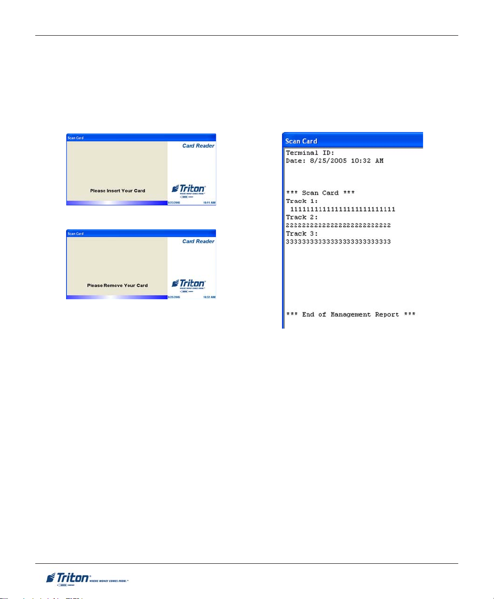
MODEL FT7000XP USER MANUAL
SCAN CARD
ACCESS INSTRUCTIONS:
1. From the DIAGNOSTICS screen, select the CARD READER option by pressing number <2> on the keypad.
2. From the CARD READER screen, select the SCAN CARD option by pressing number <2> on the keypad.
DESCRIPTION:
The SCAN CARD function reports the number of tracks the card reader is able to scan. It prompts you to insert
and remove a card. Upon removing the card, a management report dialog is displayed. If the card can be read
properly, the information from the tracks on the card will be displayed. This report can be printed to the receipt
printer or saved to an external memory device.
NOTE: This option can only be performed from the front operator panel.
70
Page 81

MANAGEMENT FUNCTIONS
TRACK 3 READ/WRITE
ACCESS INSTRUCTIONS:
1. From the DIAGNOSTICS screen, select the CARD READER option by pressing number <2> on the keypad.
2. From the CARD READER screen, select the TRACK 3 READ/WRITE option by pressing number <3> on the
keypad.
DESCRIPTION:
The TRACK 3 READ / WRITE function reads and retains existing Track 3 data, writes a specific data pattern to
track 3, reads and verifies the data pattern written, and restores (writes) the original track 3 data to the card.
NOTE: This option can only be performed from the front operator panel.
RESET
ACCESS INSTRUCTIONS:
1. From the DIAGNOSTICS screen, select the CARD READER option by pressing number <2> on the keypad.
2. From the CARD READER screen, select the RESET option by pressing number <4> on the keypad.
DESCRIPTION:
The RESET function resets the card reader and displays card reader status report.
71
Page 82

MODEL FT7000XP USER MANUAL
PRINTER
ACCESS INSTRUCTIONS:
1. From the DIAGNOSTICS screen, select the PRINTER option by pressing number <3> on the keypad.
DESCRIPTION:
The PRINTER option allows the terminal operator to perform the following functions:
1. DEVICE STATUS. Displays a management report that shows current operational status of the receipt
printer.
2. PRINT TEST DATA . Allows user to perform an operational test of the printer.
3. RESET. Resets the printer and displays a status report.
72
Page 83

MANAGEMENT FUNCTIONS
DEVICE STATUS
ACCESS INSTRUCTIONS:
1. From the DIAGNOSTICS screen, select the PRINTER option by pressing number <3> on the keypad.
2. From the PRINTER screen, select the DEVICE STATUS option by pressing number <1> on the keypad.
DESCRIPTION:
The DEVICE STATUS function displays a report that shows the current operational status of the printer type,
firmware version, SP version, device status (Healthy, Fatal, or No Device), media status (Present / Not Present),
paper status (Full, Low, or Out), and printer position (Front or Rear).
This status is displayed in a management report dialog which you can print to the receipt printer or save to an
external memory device.
73
Page 84

MODEL FT7000XP USER MANUAL
PRINT TEST DATA
ACCESS INSTRUCTIONS:
1. From the DIAGNOSTICS screen, select the PRINTER option by pressing number <3> on the keypad.
2. From the PRINTER screen, select the PRINT TEST DATA option by pressing number <2> on the keypad.
DESCRIPTION:
The PRINT TEST DATA function re-initializes and then performs an operational test of the printer. A pattern of
characters is printed out to the receipt printer using the variety of characters, fonts, and sizes to test the print
capability.
When the test is completed, the user will be prompted to either perform another test or exit and go back to the
Printer menu.
RESET
ACCESS INSTRUCTIONS:
1. From the DIAGNOSTICS screen, select the PRINTER option by pressing number <3> on the keypad.
2. From the PRINTER screen, select the RESET option by pressing number <3> on the keypad.
DESCRIPTION:
The RESET function resets the printer and displays the printer status report. This status is displayed in a
management report dialog which you can print to the receipt printer or save to an external memory device.
74
Page 85

MANAGEMENT FUNCTIONS
KEYPAD
ACCESS INSTRUCTIONS:
1. From the DIAGNOSTICS screen, select the KEYPAD option by pressing number <4> on the keypad.
DESCRIPTION:
The KEYPAD option allows the terminal operator to perform the following functions:
1. KEYPAD DEVICE STATUS. Displays a management report that shows current operational status of the
keypad device.
2. TEST KEYPAD. Displays a dialog box showing the state (down/up) of any keypad button.
3. CLEAR TAMPER. Allows user to reset keypad tamper errors, if applicable.
4. RESET. Resets the keypad and displays a status report.
75
Page 86

MODEL FT7000XP USER MANUAL
KEYPAD DEVICE STATUS
ACCESS INSTRUCTIONS:
1. From the DIAGNOSTICS screen, select the KEYPAD option by pressing number <4> on the keypad.
2. From the KEYPAD screen, select the KEYPAD DEVICE STATUS option by pressing number <1> on the
keypad.
DESCRIPTION:
The KEYPAD DEVICE STATUS function displays a report that shows the current operational status of the keypad
device. In addition, the status of the encryption features is also reported including check digits and whether
various encryption features are loaded.
This status is displayed in a management report dialog which you can print to the receipt printer or save to an
external memory device.
76
Page 87

MANAGEMENT FUNCTIONS
TEST KEYPAD
ACCESS INSTRUCTIONS:
1. From the DIAGNOSTICS screen, select the KEYPAD option by pressing number <4> on the keypad.
2. From the KEYPAD screen, select the TEST KEYPAD option by pressing number <2> on the keypad.
DESCRIPTION:
The TEST KEYPAD function enables you to verify proper operation of the numeric, function, and control buttons
of the terminal. Press any button (except the <Cancel> button) and the report dialog will indicate the state of
the button (ie; Pressed). When done testing all the keys, press <Cancel> to exit and return to the Keypad menu.
77
Page 88

MODEL FT7000XP USER MANUAL
CLEAR TAMPER
ACCESS INSTRUCTIONS:
1. From the DIAGNOSTICS screen, select the KEYPAD option by pressing number <4> on the keypad.
2. From the KEYPAD screen, select the CLEAR TAMPER option by pressing number <3> on the keypad.
DESCRIPTION:
The CLEAR TAMPER function enables you to reset a tamper condition of the encrypting PIN pad if one exists.
The PIN pad must be cleared of the tamper condition before entering encrypted master keys via Key Management or downloaded from the host network.
RESET
ACCESS INSTRUCTIONS:
1. From the DIAGNOSTICS screen, select the KEYPAD option by pressing number <4> on the keypad.
2. From the KEYPAD screen, select the RESET option by pressing number <4> on the keypad.
DESCRIPTION:
The RESET function resets the keypad and displays the keypad status report.
78
Page 89

MANAGEMENT FUNCTIONS
GENERAL I/O DIAGNOSTICS
ACCESS INSTRUCTIONS:
1. From the DIAGNOSTICS screen, select the GENERAL I/O DIAGNOSTICS option by pressing number <5> on
the keypad.
DESCRIPTION:
The GENERAL I/O DIAGNOSTICS option allows the terminal operator to perform the following functions:
1. LED INDICATORS. When selected, this function will flash all LEDs for 5 seconds. When the “LED
Indicators” is selected from the Diagnostics menu at the rear LCD, the general acknowledgement
dialog screen appears and directs a user to switch the screen to the front LCD.
79
Page 90

MODEL FT7000XP USER MANUAL
2. HEADPHONE TEST. This option reports whether
the headphones can be detected (inserted or
removed). This status is displayed in a
management report dialog which you can print
to the receipt printer or save to an external
memory device.
NOTE: This option can only be performed from the
front operator panel.
3. SAFE DOOR TEST. Allows user to test safe door
switch. The management report displays open/
closed conditions. When the “Safe Door Test”
is selected from the Diagnostics menu at the
front LCD, the general acknowledgement
dialog screen appears and directs a user to
switch the screen to the rear LCD. This status
is displayed in a management report dialog
which you can print to the receipt printer or
save to an external memory device.
80
Page 91

MANAGEMENT FUNCTIONS
4. CABINET DOOR T EST. Allows user to test cabinet
door switches. The management report
displays open/closed conditions. When the
“Cabinet Door Test” is selected from the
Diagnostics menu at the front LCD, the general
acknowledgement dialog screen appears and
directs a user to switch the screen to the rear
LCD. This status is displayed in a management
report dialog which you can print to the receipt
printer or save to an external memory device.
5. PRINTER POSITION TEST. This status is
displayed in a management report dialog which
you can print to the receipt printer or save to
an external memory device.
6. PREVIEW SAMPLE VOICE. If headphones are
inserted, speaks a sample voice track.
81
Page 92

MODEL FT7000XP USER MANUAL
ENVELOPE DEPOSITORY
ACCESS INSTRUCTIONS:
1. From the DIAGNOSTICS screen, select the ENVELOPE DEPOSITORY option by pressing number <6> on the
keypad.
DESCRIPTION:
The ENVELOPE DEPOSITORY option allows the terminal operator to perform the following functions:
1. ENVELOPE DEPOSITORY STATUS. Displays a management report that shows current depository hardware
status.
2. ENVELOPE A CCEPT TEST. Commands the depository to accept an envelope.
3. ENVELOPE RETURN TEST. Commands the depository to accept an envelope, print data, and then return
the envelope.
4. ENVELOPE DISPENSE AND RETRACT. Commands the depository to dispense an envelope, print data, and
then retract the envelope.
5. ENVELOPE LENGTH TEST. This function checks the envelope for appropriate length.
6. SHUTTER TEST. This function currently not available.
7. RESET. Resets the envelope depository and displays the status report.
82
Page 93

MANAGEMENT FUNCTIONS
ENVELOPE DEPOSITORY STATUS
ACCESS INSTRUCTIONS:
1. From the DIAGNOSTICS screen, select the ENVELOPE DEPOSITORY option by pressing number <6> on the
keypad.
2. From the ENVELOPE DEPOSITORY screen, select the ENVELOPE DEPOSITORY STATUS option by pressing
number <1> on the keypad.
DESCRIPTION:
The ENVELOPE DEPOSITORY STATUS report identifies the type of depository mechanism installed and shows the
results of the most recent depository status check. The report includes depository type, firmware version, SP
version, device status (Healthy, Fatal, or No Device), and statuses of the media, bin, shutter, and printer.
This report is displayed in a management report dialog that can be printed by the receipt printer or saved to an
external memory device.
83
Page 94

MODEL FT7000XP USER MANUAL
ENVELOPE A CCEPT TEST
ACCESS INSTRUCTIONS:
1. From the DIAGNOSTICS screen, select the ENVELOPE DEPOSITORY option by pressing number <6> on the
keypad.
2. From the ENVELOPE DEPOSITORY screen, select the ENVELOPE A CCEPT TEST option by pressing number
<2> on the keypad.
DESCRIPTION:
The ENVELOPE A CCEPT TEST accepts an envelope, prints the data, and stores the inserted envelope, if envelope
is normal. If the inserted envelope is too long or short, it will be returned and prompts the operator to retrieve
it.
The printed data on the envelope is printed as follows:
0123456789*,~./:+$#
ABCDEFGHIJKLMNOPQRSTUVWXYZabcdefghijklmnopqrstuvwxyz
After the test is completed, press <1> to repeat the test or <2> to exit back to the Envelope Depository menu.
84
Page 95

MANAGEMENT FUNCTIONS
ENVELOPE RETURN TEST
ACCESS INSTRUCTIONS:
1. From the DIAGNOSTICS screen, select the ENVELOPE DEPOSITORY option by pressing number <6> on the
keypad.
2. From the ENVELOPE DEPOSITORY screen, select the ENVELOPE RETURN TEST option by pressing number
<3> on the keypad.
DESCRIPTION:
The ENVELOPE RETURN TEST accepts an envelope, prints the data, and returns the inserted envelope.
The printed data on the envelope is printed as follows:
0123456789*,~./:+$#
ABCDEFGHIJKLMNOPQRSTUVWXYZabcdefghijklmnopqrstuvwxyz
After the test is completed, press <1> to repeat the test or <2> to exit back to the Envelope Depository menu.
85
Page 96

MODEL FT7000XP USER MANUAL
ENVELOPE DISPENSE AND RETRACT TEST
ACCESS INSTRUCTIONS:
1. From the DIAGNOSTICS screen, select the ENVELOPE DEPOSITORY option by pressing number <6> on the
keypad.
2. From the ENVELOPE DEPOSITORY screen, select the ENVELOPE DISPENSE AND RETRACT TEST option by
pressing number <4> on the keypad.
DESCRIPTION:
The ENVELOPE DISPENSE AND RETRACT TEST tests the dispensing capability of the envelope depository. The
test dispenses an envelope and then automatically retracts it into the depository storage bin.
After the test is completed, press <1> to repeat the test or <2> to exit back to the Envelope Depository menu.
86
Page 97

MANAGEMENT FUNCTIONS
ENVELOPE LENGTH TEST
ACCESS INSTRUCTIONS:
1. From the DIAGNOSTICS screen, select the ENVELOPE DEPOSITORY option by pressing number <6> on the
keypad.
2. From the ENVELOPE DEPOSITORY screen, select the ENVELOPE LENGTH TEST option by pressing number
<5> on the keypad.
DESCRIPTION:
The ENVELOPE LENGTH TEST tests the sensors that detect a long or short envelope. The test accepts an
envelope, checks the length, and returns the inserted envelope.
After the test is completed, press <1> to repeat the test or <2> to exit back to the Envelope Depository menu.
87
Page 98

MODEL FT7000XP USER MANUAL
SHUTTER TEST (ENVELOPE DEPOSITORY)
ACCESS INSTRUCTIONS:
1. From the DIAGNOSTICS screen, select the ENVELOPE DEPOSITORY option by pressing number <6> on the
keypad.
2. From the ENVELOPE DEPOSITORY screen, select the SHUTTER TEST option by pressing number <7> on the
keypad.
DESCRIPTION: TBD
RESET
ACCESS INSTRUCTIONS:
1. From the DIAGNOSTICS screen, select the ENVELOPE DEPOSITORY option by pressing number <6> on the
keypad.
2. From the ENVELOPE DEPOSITORY screen, select the RESET option by pressing number <8> on the keypad.
DESCRIPTION:
The RESET function resets the envelope depository and displays the depository status report. This report is
displayed in a management report dialog that can be printed to the receipt printer or saved to an external
memory device.
88
Page 99

MANAGEMENT FUNCTIONS
ELECTRONIC JOURNAL
ELECTRONIC JOURNAL
ELECTRONIC JOURNAL MENU OPTIONS ............................................................................. 90
EXPORT UNAUDITED RECORDS .......................................................................................... 91
DISPLAY LAST X RECORDS ............................................................................................... 92
JOURNAL STATISTICS ......................................................................................................... 93
JOURNAL SETTINGS ........................................................................................................... 94
AUTO EXPORT ........................................................................................................................................ 94
AUTO DELETE ........................................................................................................................................ 94
DELETE INTERVAL (DAY S) ....................................................................................................................... 95
DELETE RECORDS OLDER THAN (DAY S) .................................................................................................. 95
SAV E SETTINGS ....................................................................................................................................... 95
89
Page 100

MODEL FT7000XP USER MANUAL
ELECTRONIC JOURNAL
ACCESS INSTRUCTIONS:
1. From the MAIN MENU screen, select the ELECTRONIC JOURNAL option by pressing number <3> on the
keypad.
DESCRIPTION:
The ELECTRIC JOURNAL option allows the terminal operator to perform the following functions:
1. EXPORT UNAUDITED RECORDS. This function is used to save all unaudited records in the electronic
journal to an external storage device.
2. DISPLAY LAST X RECORDS. This function is used to display and print records from the electronic journal
either before or after they have been audited.
3. JOURNAL STATISTICS. This function displays a management report with electronic journal information.
4. JOURNAL SETTINGS. This function sets the parameters that will allow the electronic journal data to be
exported daily or deleted at a predefined schedule based on the time in days and age of the records.
90
 Loading...