

Page 1

MODEL FT7000
XP
“FULL FUNCTION ATM”
SITE PREPARATION / INSTALLATION GUIDE
TDN 07102-00072C Jun 1 2009
CORPORATE HEADQUARTERS:
522 E. Railroad Street
Long Beach, MS 39560
Phone: (228) 868-1317
Fax: (228) 868-0437
COPYRIGHT NOTICE
© 2008 Triton. All Rights Reserved. TRITON logo is a
registered trademark of Triton Systems of Delaware.
Page 2

DOCUMENT UPDATES
Sep 2007 Original
Apr 10 2009
Added changes to illustrations on pages 23 and 24 to provide better
guidance in creating the wall opening.
Edit illustration on pg 18 for minimum service requirements.
Jun 1 2009
Added removal of shipping thumb screws in Motorized tray, Depository,
and Printer assemblies on pg 38,39.
2
Page 3

FT7000XP - SITE PREPARATION AND INSTALLATION GUIDE
INTRODUCTION
The Triton FT7000
vestibule location. The cabinet designs allow flexibility for walk-up (wall thickness up to 14") or drivethrough ( wall thickness up to 12") installations. Built-in leveling feet allow the unit to be raised to the
desired height of the wall opening. The following section provides the physical dimensions and requirements for installing the FT7000XP for your particular site location. To assist you in preparing your site, a
check list is provided of various procedures that should be carried out prior to the arrival of the ATM.
XP
is a self-serviced, weatherized terminal adaptable for any suitable exterior wall or
WHAT’S IN THIS INSTALLATION GUIDE
This Installation Guide provides information for the preparation and installation of the FT7000XP ATM. It
contains requirements for site preparation, electrical specifications, and cabinet accessibility that comply
with all relevant codes, laws and regulations. The Installation Guide is divided into the following sections:
SITE COMPLIANCE. States the customers responsibilities for ensuring all relevant regulations are adhered
to for installing ATMs.
ATM ENVIRONMENTAL PRECAUTIONS CHECKLIST. Describes the general environmental precautions
considered when installing the ATM. To help ensure proper operation of the ATM, ensure the
environmental criteria listed in this checklist are met.
DIMENSIONS. Describes physical dimensions and service area for the FT7000
XP
.
Physical dimensions.
Service area dimensions (Preferred/Minimum).
Customer access dimensions
Wall opening and height requirements for exterior wall.
INSTALLATION. Describes the steps involved for the physical installation of the cabinet unit and all
hardware associated with.
POWER AND COMMUNICATION. Shows cable access area, power requirements, and powering-up the
unit.
ENVELOPE SUPPLY UNIT. Describes procedure for checking/adjusting envelope supply unit.
ALARM PANEL D IAGRAM. Shows the pin-out designations for facility alarm interface.
APPENDIX A. Software License Agreement / Compliance/Emissions statements
APPENDIX B. ATM Installation for Accessibility guidelines.
3
Page 4

FT7000XP - SITE PREPARATION AND INSTALLATION GUIDE
CONTENTS
TABLE OF CONTENTS ............................................................................................. 4-5
SITE COMPLIANCE .................................................................................................... 6
ENVIRONMENTAL PRECAUTIONS ................................................................................. 7
TEMPERATURE / POWER / RF INTERFERENCE REQUIREMENTS .................................................................. 8
DIMENSIONS ............................................................................................................ 9
PHYSICAL DIMENSIONS
FRONT / O VERHEAD VIEWS ................................................................................................................. 10
SIDE VIEW ......................................................................................................................................... 11
REAR VIEW ........................................................................................................................................ 12
PREFERRED SERVICE A REA DIMENSIONS
1 DOOR - VAULT (LEVEL 1) .................................................................................................................. 13
2 DOOR - BUSINESS HOURS/VAULT (LEVEL 1) ........................................................................................ 14
MINIMUM SERVICE A REA DIMENSIONS
2 DOOR - BUSINESS HOURS .................................................................................................................. 15
2 DOOR - VAULT (LEVEL 1) - FUJITSU DISPENSER ................................................................................... 16
2 DOOR - VAULT (LEVEL 1) - NMD-100 DISPENSER .............................................................................. 17
1 DOOR - VAULT (LEVEL 1) - FUJITSU DISPENSER ................................................................................... 18
1 DOOR - VAULT (LEVEL 1) - NMD-100 DISPENSER .............................................................................. 19
CUSTOMER A CCESS DIMENSIONS
WALK-UP ATM ................................................................................................................................. 20
DRIVE-UP ATM .................................................................................................................................. 21
WALL OPENING / HEIGHT R EQUIREMENTS (EXTERIOR WALL) ..................................... 22
DIAGRAM A ....................................................................................................................................... 23
DIAGRAM B ........................................................................................................................................ 24
INSTALLATION .......................................................................................................... 25
BEFORE YOU S TART ............................................................................................................................. 26
TOOLS REQUIRED / UNIT WEIGHTS ...................................................................................................... 27
UNPACKING THE UNIT ......................................................................................................................... 28
REMOVE / INSTALL F510 DISPENSER ..................................................................................................... 29
REMOVE / INSTALL NMD-100 DISPENSER ............................................................................................. 34
ENVELOPE DEPOSIT BIN ...................................................................................................................... 38
LEVELING FEET ................................................................................................................................... 38
INSTALLING UNIT / TRIM HARDWARE ................................................................................................. 39 THRU 44
ELECTRONIC LOCK (LAGARD)................................................................................. 45
4
Page 5

FT7000XP - SITE PREPARATION AND INSTALLATION GUIDE
CONTENTS
POWER AND COMMUNICATION .................................................................................. 51
CONNECT POWER / COMMUNICATION CABLES ........................................................................................ 52
POWER-UP THE UNIT ........................................................................................................................... 53
ENVELOPE SUPPLY UNIT ........................................................................................... 55
TEST DISPENSE / RETRACT ENVELOPES ................................................................................................. 56
ADJUST ENVELOPE THICKNESS ............................................................................................................. 57
ALARM PANEL DIAGRAM .......................................................................................... 58
APPENDIX A - SOFTWARE LICENSE A GREEMENT / COMPLIANCE/EMISSIONS STATEMENTS
APPENDIX B - ATM INSTALLATION FOR A CCESSIBILITY
5
Page 6
FT7000XP - SITE PREPARATION AND INSTALLATION GUIDE
SITE COMPLIANCE
This document contains the information necessary for the preparation and installation of an FT7000
Triton ATM. It’s important that the site complies with the requirements specified in this document. In
addition, electrical wiring and mechanical systems must also comply with all relevant laws and regulations.
The site must be prepared by the customer or his agent who is fully conversant with the requirements of
installing through-the-wall ATM equipment. The responsibility for ensuring that the site is prepared in
compliance with this document remains with the customer.
For information and guidance only, a list is provided in general terms of those matters for which the
customer is responsible. The list is not intended to be comprehensive and in no way modifies, alters, or
limits the responsibility of the customer for all aspects of adequate site preparation.
1. Location of the equipment and site preparation.
2. Site wiring (power, communication).
3. Location of other equipment that may cause electrical, electromagnetic or heat induced interference.
4. Make building alterations to meet wiring and other site requirements.
5. Install all communication cables, wall jacks, and associated hardware.
6. Provide and install necessary power distribution boxes, conduits, and grounds.
7. Ensure all applicable codes, regulations, and laws (electrical, building, safety) are adhered to.
8. Ensure the environmental requirements of this unit are met.
9. Install the unit at a height which meets the ADA/DDA/CSA accessibility regulations for the state/
country installed.
XP
TSILKCEHCNOITARAPERPETIS
nalproolfangiseddnaetistceleS
temsnoitidnoclatnemnorivneerusnE
seludehcsrodnevdnarotcartnochsilbatsE
stnemeriuqerenilnoitacinummockcehC
sdeenyrosseccanoitallatsninalP
snoitaretlayrassecenekamdnanalproolfkcehC
stnemeriuqerlacirtcelellatsnI
sdeennoitacinummocrofetiseraperP
)lanoitpo(gniniartrotareponalP
tsetdnasenilnoitacinummocllatsnI
elbaliavaeraseirosseccanoitallatsnierusnE
nitneserpsitahterawdrah/snoitcurtsboynaevomeR
.dellatsniebotsitnempiuqeMTAehthcihwniaeraeht
6
Page 7

ENVIRONMENTAL PRECAUTION CHECKLIST
7
Page 8

ATM ENVIRONMENTAL P RECAUTIONS CHECKLIST
When installing an ATM, some general environmental and power precautions need to be considered. Evaluate the location where the ATM will be
installed. To help ensure proper operation of the ATM, ensure the environmental criteria listed in this checklist are met.
TEMPERATURE/HUMIDITY
1. The ATM will operate over a range of tempera-
tures and humidity. Generally, these parameters must fall within the following ranges:
Temperature (Vault/Electronics)
• 10°C to 40°C
• 50°F to 104° F
Relative Humidity
• 20% to 80%
• (Non-Condensing)
Temperature (External)
• -35°C to 50°C
• -30°F to 122°F
Relative Humidity
• 20% to 100%
AC POWER REQUIREMENTS
2. Ensure the following AC power requirements
are met:
Current (Max)
• 4.0 to 6.0A @ 120V
• 2.0 to 4.0A @ 240V
Dedicated source. The ATMs AC power feed will be
a dedicated line to which no other electrical devices
are connected. The ATM power line will be wired for
a single “duplex”-style outlet and connected directly
to the AC service panel.
Isolated Ground. An equipment grounding conductor that is insulated from the conduit or raceway and
all other grounding points throughout its entire
length. The only points of electrical connection will
be at the duplex outlet and service panel ends of the
line.
* IMPORTANT *
AC power for the terminal should
come from a dedicated source with
an isolated ground.
RF INTERFERENCE
3. Ensure there are no devices near the terminal
that may cause RF interference, such as:
TVs
Security devices
Devices with compressors
Voltage
• 90V to 136V @ 50/60 Hz
• 198V to 257V @ 50/60 Hz
Power Consumption (Idle)
• 2.0A @ 115 VAC at 60 Hz
• 1.0A @ 230 VAC at 50 Hz
Power Consumption (Max Load)
• 606 Watts @ 120V
• 482 Watts @ 240V
8
Page 9
DIMENSIONS
NOTE
Dimensions listed comply with US Federal ADA Guidelines. For USA
installations, check for additional guidance. For non-USA installations,
check regulations relating to the country of install.
9
Page 10
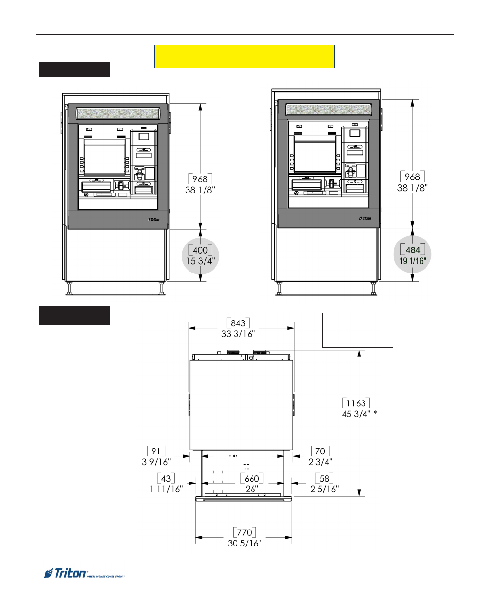
Front View
FT7000
XP
- SITE PREPARATION AND INSTALLATION GUIDE
PHYSICAL DIMENSIONS
BUSINESS HOURS
Overhead View
BUSINESS HOURS /
LEVEL 1 (VAULT)
LEVEL 1
(VAULT)
* Subtract 2"
[51mm]
for Drive-up ATM
10
Page 11
Side View
X
LEVEL 1
(VAULT)
SITE PREPARATION / INSTALLATION
PHYSICAL DIMENSIONS
* Subtract 2" [51mm]
for Drive-up ATM
muminiM mumixaM
]mm14["8/5-1]mm503["21
.]mm201["4tsaeltaeb
tnemtsujdAhtnilP
s
foeulavehtybdetneserper( 'X'
)
tellapagnidilsybMTAehtevomotredronI:etoN
,htnilpehtdnatluavehtneewtebkcaj
'X'
tsum
* Subtract 2" [51mm]
for Drive-up ATM
BUSINESS
HOURS
X
11
Page 12
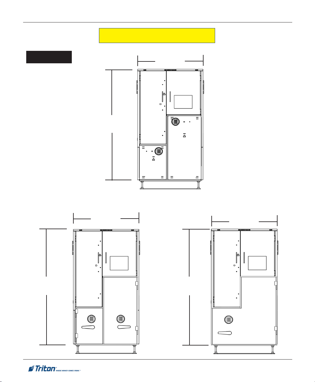
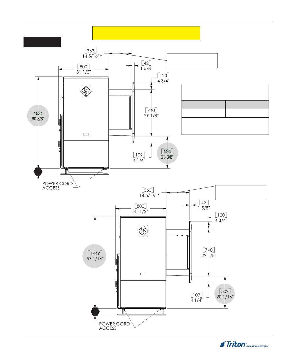
FT7000XP - SITE PREPARATION AND INSTALLATION GUIDE
PHYSICAL DIMENSIONS
Rear View
BUSINESS HOURS
2-DOOR
LEVEL 1 (VAULT)
2-DOOR
[1449]
57 - 1/16"
[843]
33 - 3/16"
[843]
33 - 3/16"
LEVEL 1 (VAULT)
1-DOOR
[843]
33 - 3/16"
[1534]
60 - 3/8"
[1534]
60 - 3/8"
12
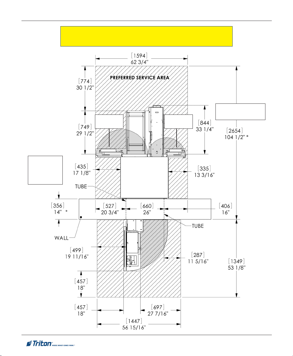
Page 13

SITE PREPARATION / INSTALLATION
PREFERRED SERVICE A REA DIMENSIONS
LEVEL 1 (VAULT) - 1 DOOR
DOOR SWING
180°
* Subtract 2" [51mm]
for Drive-up ATM
* Subtract 2" [51mm]
for Drive-up ATM
13
Page 14
* Subtract 2"
[51mm]
for Drive-up
AT M
FT7000XP - SITE PREPARATION AND INSTALLATION GUIDE
PREFERRED SERVICE AREA DIMENSIONS
BUSINESS HOURS / LEVEL 1 (VAULT) - 2 DOOR
* Subtract 2" [51mm]
DOOR SWING
180°
DOOR SWING
180°
for Drive-up ATM
14
Page 15
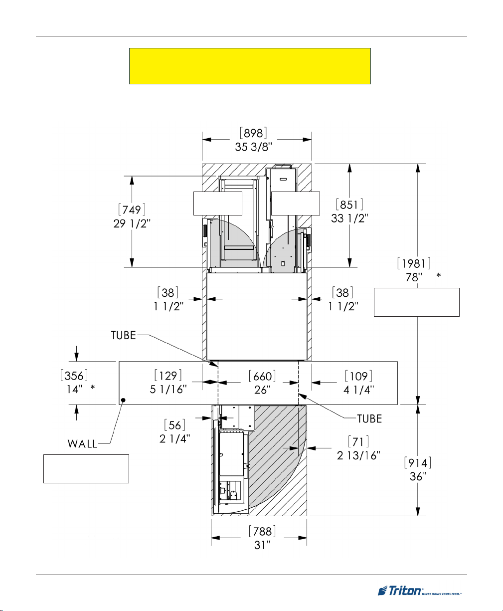
SITE PREPARATION / INSTALLATION
MINIMUM SERVICE AREA DIMENSIONS
BUSINESS HOURS - 2 DOOR
NOTE: THIS CABINET ONLY AVAILABLE WITH FUJITSU DISPENSING MECHANISM
* Subtract 2" [51mm]
for Drive-up ATM
DOOR SWING
90°
DOOR SWING
90°
* Subtract 2" [51mm]
for Drive-up ATM
15
Page 16
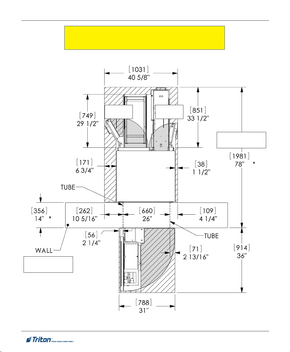
FT7000XP - SITE PREPARATION AND INSTALLATION GUIDE
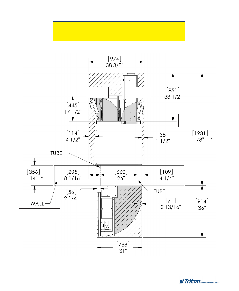
MINIMUM SERVICE AREA DIMENSIONS
LEVEL 1 (VAULT) - 2 DOOR (FUJITSU DISPENSER)
* Subtract 2" [51mm]
for Drive-up ATM
DOOR SWING
120°
DOOR SWING
100°
* Subtract 2" [51mm]
for Drive-up ATM
16
Page 17
SITE PREPARATION / INSTALLATION
MINIMUM SERVICE AREA DIMENSIONS
LEVEL 1 (VAULT) - 2 DOOR (NMD-100 DISPENSER)
* Subtract 2" [51mm]
for Drive-up ATM
DOOR SWING
110°
DOOR SWING
100°
* Subtract 2" [51mm]
for Drive-up ATM
17
Page 18
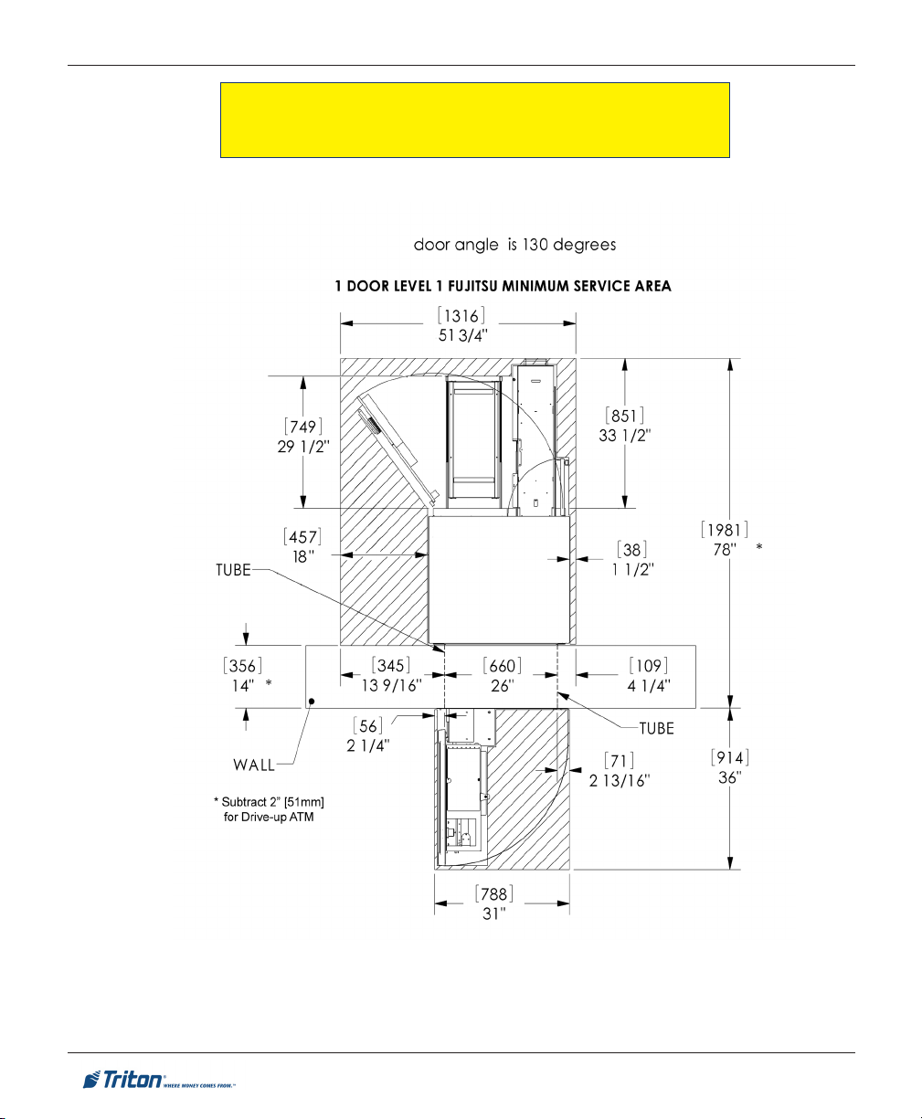
FT7000XP - SITE PREPARATION AND INSTALLATION GUIDE
MINIMUM SERVICE AREA DIMENSIONS
LEVEL 1 (VAULT) - 1 DOOR (FUJITSU DISPENSER)
18
Page 19

SITE PREPARATION / INSTALLATION
MINIMUM SERVICE AREA DIMENSIONS
LEVEL 1 (VAULT) - 1 DOOR (NMD-100 DISPENSER)
DOOR SWING
125°
* Subtract 2" [51mm]
for Drive-up ATM
* Subtract 2" [51mm]
for Drive-up ATM
19
Page 20

Walk-up ATM
FT7000XP - SITE PREPARATION AND INSTALLATION GUIDE
CUSTOMER ACCESS DIMENSIONS
1yeKnoitcnuFpoT
2resnepsiDhsaC
3
4yrotisopeDepolevnE
5redaeRdraCpiD
6
7retnirPtpieceR
snoisnemiDsseccAremotsuC
)MTApu-klaW(
erutaeF
yeK5#
)dapyeKniaM(
draCdezirotoM
redaeR
thgieH
)sruoHssenisuB(
"4/1-73
)mm749(
"61/9-82
)mm527(
"8/3-62
)mm966(
"8/5-72
)mm107(
"61/51-82
)mm637(
"8/5-23
)mm828(
"61/3-83
)mm079(
*etoN*
thgieH
)tluaV-1leveL(
"61/9-04
)mm0301(
"8/7-13
)mm018(
"61/11-92
)mm457(
"61/51-03
)mm687(
"4/1-23
)mm918(
"61/51-53
)mm319(
"2/1-14
)mm4501(
)teefgnileveltuohtiw(
htpeD
"6
)mm251(
"7.5
)mm541(
"4
)mm201(
"9.3
)mm99(
"3.4
)mm901(
"9.3
)mm99(
"9.3
)mm99(
tenibacfomottobmorfdecnerefererasnoisnemidthgieH
.lenapmirtfotnorfmorfdecnerefererasnoisnemidhtpeD
Control panel
20
Page 21

Drive-up ATM
SITE PREPARATION / INSTALLATION
CUSTOMER ACCESS DIMENSIONS
1yeKnoitcnuFpoT
2resnepsiDhsaC
3
4yrotisopeDepolevnE
5redaeRdraCpiD
6
7retnirPtpieceR
snoisnemiDsseccAremotsuC
)MTApu-evirD(
erutaeF
yeK5#
)dapyeKniaM(
draCdezirotoM
redaeR
thgieH
)sruoHssenisuB(
"61/9-63
)mm929(
"61/9-82
)mm527(
"52
)mm636(
"8/5-72
)mm107(
"61/51-82
)mm637(
"8/5-23
)mm828(
"61/3-83
)mm079(
*etoN*
thgieH
)tluaV-1leveL(
"8/7-93
)mm3101(
"8/7-13
)mm018(
"61/5-82
)mm917(
"61/51-03
)mm687(
"4/1-23
)mm918(
"61/51-53
)mm319(
"2/1-14
)mm4501(
)teefgnileveltuohtiw(
htpeD
"1.3
)mm97(
"7.3
)mm49(
"7.2
)mm96(
"9.1
)mm84(
"3.2
)mm85(
"9.1
)mm84(
"9.1
)mm84(
tenibacfomottobmorfdecnerefererasnoisnemidthgieH
.lenapmirtfotnorfmorfdecnerefererasnoisnemidhtpeD
Control panel
21
Page 22

FT7000XP - SITE PREPARATION AND INSTALLATION GUIDE
WALL OPENING / HEIGHT REQUIREMENTS
(EXTERIOR WALL)
(CRITICAL)
The Difference in Elevation is the most critical dimension to consider when installing the FT7000. Use
whatever method you feel comfortable with to determine this dimension. To meet ADA outside height
requirements, refer to the chart below and figures on the following pages. The size of the opening will
not change, but its vertical position will to meet these requirements.
TO MEET ADA REQUIREMENTS:
If difference in elevation is less than 10-11/16" [272 mm] - Business Hours or
7-7/16" [189 mm] - Level 1 (vault), see Diagram A (page 23) .
If difference in elevation is more than 10-11/16" [272 mm] - Business Hours
or 7-7/16" [189 mm] - Level 1 (vault), see Diagram B (page 24).
snoisnemiDgninepOllaW**dnuorGroiretxEmorfthgieH***
thgieH htdiW ecnailpmoCADA ecnailpmoCADD
"526.13
]mm408[
**
"52.72
]mm309[
***
snoisnemidgninepolautcA
"4/3-03
]mm187[
dnuorgroiretxeehtmorf)ADD("54
"4/3-72
]mm507[
.mottobebutMTAotderusaeMsnoisnemidesehT
ro)ADA("84gniebmetihcaertsehgihehtnodesabera
22
Page 23

SITE PREPARATION / INSTALLATION
DIAGRAM A
DIFFERENCE IN ELEVATION (INSIDE FLOOR/EXTERIOR
GROUND
) LESS THAN 10-11/16" (272 MM)
To meet ADA requirements:
Dimension ‘A’ must not exceed 30 - 3/4" [781 mm].
Dimension ‘B’ = Dimension ‘A’ minus the difference in elevation.
Note: Dimension ‘A’ is the distance from the bottom of the tube to the
exterior ground.
Dimension ‘B’ is the distance from the bottom of the tube to the
interior floor.
23
Page 24

FT7000XP - SITE PREPARATION AND INSTALLATION GUIDE
DIAGRAM B
DIFFERENCE IN ELEVATION (INSIDE FLOOR/EXTERIOR
GROUND
) GREATER THAN 10-11/16" (272 MM)
If the interior surface is greater than 11 inches higher than the exterior, the leveling feet might not retract
sufficiently to meet the ADA requirement. In this case a ramp will be required outside. Ensure it meets
ADA specifications for access. If the interior surface is lower than the exterior, the leveling feet can be
extended, but it may be more secure and stable to build a platform under the ATM to ensure the external
ADA height requirement is met. Ensure the platform is capable of supporting the weight of the FT7000.
24
Page 25

INSTALLATION
25
Page 26

FT7000XP - SITE PREPARATION AND INSTALLATION GUIDE
BEFORE Y OU STA RT
It’s recommended that the unit be secured to the facility floor. The footprint of the cabinet floor allows for
securing the unit through the leveling feet “plinth” hardware, regardless of how high the unit may be
raised. It is the customer or their agent’s responsibility to determine how/where the unit is affixed to the
facility. Listed are some general considerations when securing the unit:
What is the floor structure (concrete, wood, etc)? Is the unit a UL Level 1 safe cabinet or Business
Hours? Will the floor support the weight of the cabinet?
Is the inside floor the same level as the outside ground? Will the unit need to be raised/lowered using
the cabinet leveling feet (mounted to the unit’s plinth)? Leveling feet compensate for differences
between inside floor and outside ground.
Ensure that doorways and corridors leading to the point of installation are wide enough to allow the
shipping package to pass through. If access is restricted, make arrangements to unpack the unit in an
area with sufficient space and move it to the installation site.
If installing a FT7000
with the dimensions and height requirements listed in this manual. Modifications to the wall or floor
may be required.
XP
where a previous ATM was installed, verify that the wall opening is consistent
Is exterior wall solid (brick, concrete)? Wood framed? Aluminum siding? Do you need to insulate the
wall cavity?
After cabinet is anchored, is the control panel collar hardware flush against the exterior wall? Is this
trim hardware sufficiently sealed to prevent moisture from entering the control panel electronics?
Level 1 Cabinet Safety
Level 1 cabinets are considerably
heavier than Business Hours cabinets! Exercise extreme caution when
moving Level 1 cabinets! At least
two persons should work together
to move the cabinet into position
for mounting!
Tool Use / Safety
Observe ALL safety precautions
for operating hand and power
tools! Wear eye and ear protection while operating the electric
drill!
USE A BACK-SUPPORT BELT
WHEN LIFTING AND MOVING
THE ATM!
26
Page 27

SITE PREPARATION / INSTALLATION
TOOLS REQUIRED
secivedgnivom/gnitfiL
)cte,yellort/kcajgnitfil,tfilkrof,kcajtellap(
erauqsgnimarf/levelelbbub/erusaemepaT lesihc/remmaH
ksam/,selggogytefas/tlebtroppuskcaB
seohsdeot-leets
:fognitsisnoctiklooT
)cte,kluac(tnalaestnatsiser-retaW
slooTgnirohcnA
remmaHtekcos)mm91("4/3revirdwercstalfegraL
levelelbbuB
noitcetorpgniraeH
tlebtroppuskcaBrenaelcmuucavelbatroPhsurberiW
)mm21("2/1
srehsawtalf
)mm11("61/7
hcnerwxob/tekcos
dna,)mm21("2/1,)mm6("4/1
deppit-edibrac)mm51("61/9
"6tsaelta-stibllirdyrnosam
gnol)mm251(
)mm701("4/1-4x)mm21("2/1
stlobrohcnaepyt-eveels
dednemmoceRsmetI/slooT
,srabllor/rabworC
)gnikcolb(rebmulparcs
licnep/rekraM
)mm23("4/1-1otpu-)desolc/nepo(sehcnerwxob,)egral(hcnerwelbatsujdA
cte,srettuclanogaid,tesrevirdtun,srevirdwercspittalf/spillihpcitengam
gnihctamrolocroraelC:dnemmoceR
,sdnuoptoof06tsaeltaotelbatsujda,hcnerweuqroT
hcnerwtehctarro,hcnerwelbatsujda
stniopllirdgnikramrof)tnelaviuqero(hcnupretneC
selggogytefaS
)mm91("4/3
llirdcirtceleytud-yvaeh
)remmah/yrator(
stun)mm21("2/1
WEIGHTS
0007TFehtfothgieW
)etamixorppA(
ssenisuB
sruoH
sbL0001
]soliK454[
27
sbL0171
)efaS(1leveL noitarugifnoC
]soliK777[
hgih-ruoF
msinahcem
Page 28

FT7000XP - SITE PREPARATION AND INSTALLATION GUIDE
3
1
1
1
1
UNPACKING THE UNIT
*** WARNING ***
The FT7000XP unit is slightly top heavy. USE
EXTREME CAUTION! Always move/support the
unit from the FRONT! 2-personnel are
recommended when unpacking and moving the
unit!!
1. The FT7000XP will be secured on a wooden pallet. Move the pallet using a pallet jack/forklift to the
desired location before unpacking.
2. Carefully inspect the unit for any shipping damage and report any damage immediately to the shipping
company. Refer to the warranty information in the User manual for information about reporting shipping
damage.
3. After unpacking the unit, remove the four (4) bolts that secure the leveling feets “Plinth” (figure
below) to the wooden pallet.
234567890123456789012
4. From the rear of the unit, place a lifting /moving device (forklift, lifting jack, etc) under the cabinet
bottom (between the leveling bolts) and lift the unit from the pallet.
28
Page 29

SITE PREPARATION / INSTALLATION
NOTE: COMPLETE THE FOLLOWING STEPS TO REMOVE THE SHIPPING BRACKETS AND RETAINING
SCREWS
BEFORE CONTINUING THE INSTALLATION AND INITIAL OPERATIONAL CHECKOUT.
REMOVE / INSTALL F510 DISPENSER
The F510 dispensing mechanism is shipped inside the security vault (see section in this manual under
“COMBINATION LOCK” for opening lock mechanism). There are shipping brackets that secure the assembly
inside the cabinet and on the slide tray. These will have to be removed first before removing the dispenser.
Follow the procedures below for removal.
REMOVING THE F510:
1. Open the lower right rear cabinet door (2-door) or lower cabinet door (1-door).
2. REMOVE SHIPPING BRACKET FROM CABINET:
Remove the two (2) wing nuts (Business Hours) or nuts (Level 1) that secure the bracket to the cabinet.
Next, remove the two (2) thumbscrews on each side of the bracket that are secured to the dispenser.
Remove the shipping bracket. You may either discard the bracket/screws or retain for future shipment.
NOTE: THE SHIPPING BRACKET/SCREWS ARE NOT INSTALLED FOR OPERATION OF THE
UNIT!
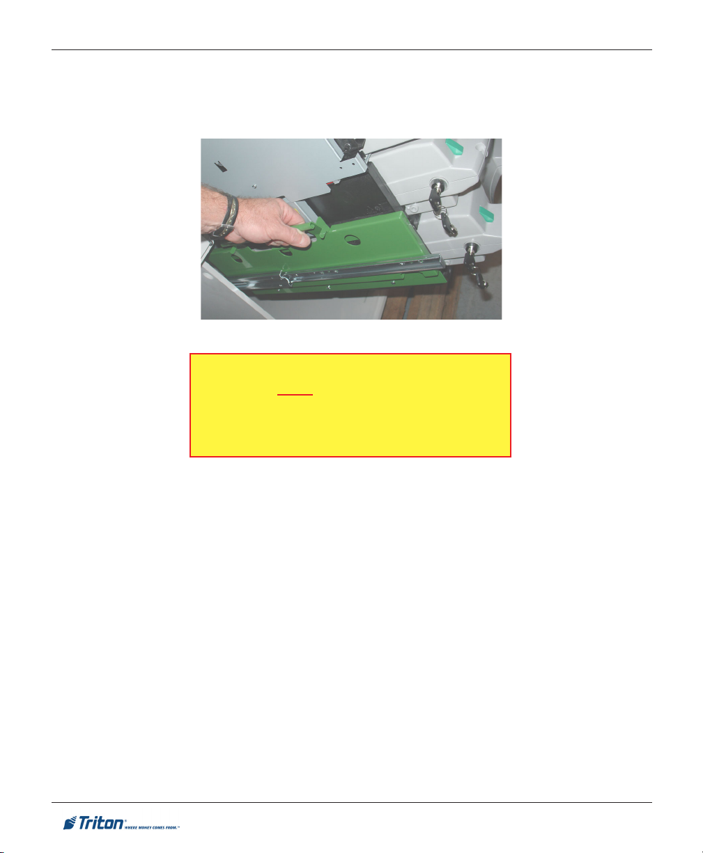
3. EXTEND DISPENSER T RAY:
Press down on the green tray latch and extend
the tray fully.
29
Page 30

FT7000XP - SITE PREPARATION AND INSTALLATION GUIDE
4. REMOVE SLIDE TRAY BRACKETS:
Remove the two (2) thumbscrews that secure
the dispenser keeper brackets to the slide tray
(each side). Remove the brackets. RETAIN THE
BRACKETS/THUMBSCREWS!
* REMINDER *
AFTER REINSTALLING THE DISPENSER
ON THE SLIDE TRAY, THE BRACKETS AND
THUMBSCREWS MUST BE REINSTALLED
FOR SECURING UNIT TO SLIDE TRAY!
5. REMOVE DISPENSER S ECURITY MODULE:
Disconnect the three (3) connectors shown from the dispenser circuit board.
Remove the two (2) screws that secure the security module bracket. Retain the screws.
Drape the bracket assembly over the door as shown.
BDU
BDSHT
RS232C
30
Page 31

SITE PREPARATION / INSTALLATION
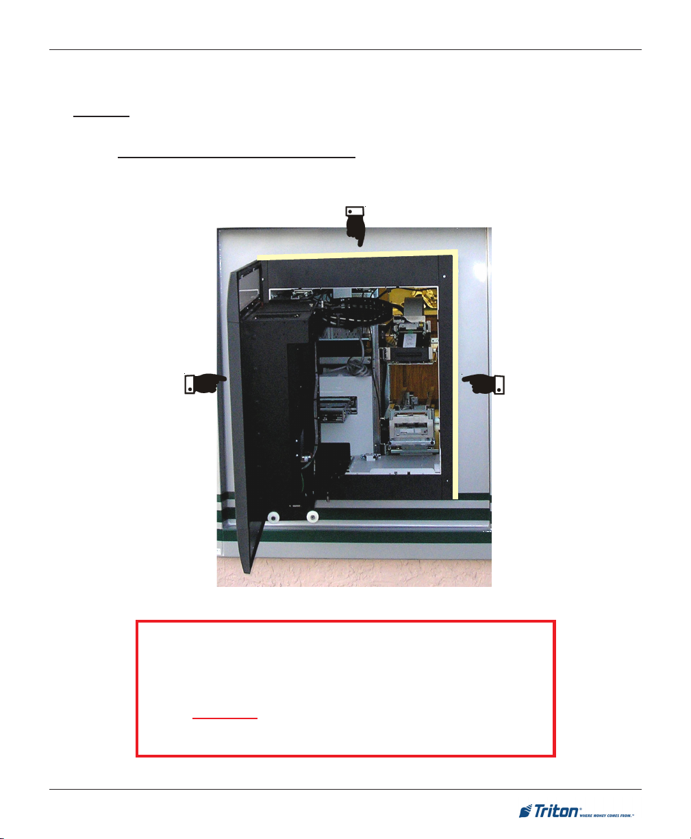
6. REMOVE DISPENSER FROM CABINET:
With 2 persons, grasp the dispenser in the areas shown (GREEN tape strips) and lift off the tray. See
weight table and warning before removal of the dispenser. Set dispenser aside.
noitarugifnoC thgieW
ettessac1]gK22[sbL94
ettessac2]gk23[sbL17
ettessac3]gKk24[sbL39
ettessac4]gK25[sbL511
resnepsiD015FehtfothgieW
)dellatsnisettessaco/w(
Two persons highly recommended to remove
*** WARNING ***
the dispenser from the cabinet. When removing dispenser from cabinet, use caution not to
damage the throat extension on front of dispenser mechanism.
7. MOVING CASSETTE S HIPPING BRACKETS:
Cassettes are shipped with hold brackets.
Remove the screw holding the bracket, reverse
bracket, and secure to the outside as shown at
right.
31
Page 32

FT7000XP - SITE PREPARATION AND INSTALLATION GUIDE
INSTALLING THE F510:
Note: Before proceeding, ensure the dispenser Security module and its attached cable track are out
of the way (see Pg.30, step 5).
*** WARNING ***
Two persons highly recommended to install
the dispenser in the cabinet. When installing
the dispenser, use caution not to damage the
throat extension on front of dispenser mechanism.
1. Push down on the dispenser tray latch (Green) and extend the slide
tray fully, locked position.
2. Hold the dispenser by the lift points marked with GREEN tape strips.
Lift and set mechanism on the tray. Note: We will position the
mechanism on the tray in a later step.
3. Push down on the dispenser tray latch (Green) and push tray slides
(with dispenser) fully into the cabinet. Release the latch and ensure
slides are locked.
4. From the rear of the dispenser, slowly push the dispenser forward until it stops against the raised
flange on the tray.
32
Page 33

SITE PREPARATION / INSTALLATION
5. Once again, push down on the dispenser tray latch (Green) and extend the slide tray fully, locked
position.
6. Remount the dispenser keeper brackets and secure with the thumbscrews (2, each side). The flange on
the brackets press up against the edge of the black plastic guide rail.
7. Reconnect the dispenser Security module to the dispenser. Next, reconnect the cables to the dispenser circuit board. Note: See mounting/connection locations on Pg. 30, step 5.
8. Push down on the dispenser tray latch (Green) and slide the dispenser fully into the cabinet. Release
the latch.
33
Page 34

FT7000XP - SITE PREPARATION AND INSTALLATION GUIDE
REMOVE / INSTALL NMD-100 DISPENSER
The NMD-100 dispensing mechanism is shipped inside the security vault (see section in this manual under
“COMBINATION LOCK” for opening lock mechanism). Follow the procedures below for removal.
REMOVING THE NMD-100:
1. Open the lower right rear cabinet door (2-door) or lower cabinet door (1-door).
2. EXTEND DISPENSER T RAY:
Pull up on the tray locking pin and extend the tray fully.
34
Page 35

SITE PREPARATION / INSTALLATION
3. DISCONNECT POWER / DATA / SHUTTER CABLES:
Disconnect the three (3) cables from the dispenser and route them out the cable entry side. Note: If the
data and shutter cables are ty wrapped to the dispenser cover, you will have to cut the ty wrap.
Power
Shutter
Data
4. REMOVE DISPENSER S ECURITY MODULE:
Pull up on the security module bracket locking pin shown.
Slide the security module bracket assembly towards the
rear of cabinet and lift assembly off the handle bracket.
Drape the bracket assembly over the door as shown
below.
35
Page 36
FT7000XP - SITE PREPARATION AND INSTALLATION GUIDE
5. REMOVE DISPENSER FROM CABINET:
With 2 persons, grasp the dispenser lift handles and lift dispenser off the slide rails. Set dispenser
aside.
*** WARNING ***
Two persons highly recommended to remove the dispenser from the cabinet. When removing dispenser
from cabinet, use caution not to damage the throat
extension on front of dispenser mechanism.
36
Page 37

SITE PREPARATION / INSTALLATION
INSTALLING THE NMD-100:
Note: Before proceeding, ensure the dispenser Security module and its attached cable track are out
of the way (see Pg.35, step 4).
*** WARNING ***
Two persons highly recommended to remove the dispenser from the cabinet. When removing dispenser
from cabinet, use caution not to damage the throat
extension on front of dispenser mechanism.
1. Extend the slide rails out fully. With 2 persons, lift and set mechanism on the rails. Note the green lift
handle brackets attached to the dispenser have notches (2 each side) that align over the round guides
on the slide rail.
2. Reinstall the security module bracket assembly to the lift handle bracket
3. Route the dispenser data, shutter, and power cables through the side cable access hole by the front
handle.
4. Reconnect the dispenser cables mentioned above to the dispenser (reference page 35).
5. Fold any excess cables in the cable trough shown. Push the side release tabs on the slide rails and
slide the dispenser fully into the cabinet. Ensure the slide rail locking pin is engaged when completed.
Slide rail
release tab
37
Page 38

FT7000XP - SITE PREPARATION AND INSTALLATION GUIDE
ENVELOPE DEPOSIT BIN
1. Open the lower left rear cabinet door (2-door) or lower cabinet door (1-door).
2. REMOVE SHIPPING T HUMBSCREW / BIN:
Remove the shipping thumbscrew that is secured to the deposit bin. You may either discard the screw
or retain for future shipment. Grasp the handle and pull depository bin from cabinet.
MOTORIZED TRAY / DEPOSITORY / PRINTER
Remove the GREEN thumb screws used to retain the above items during shipment.
GREEN thumb screw typical.
38
Page 39

LEVELING FEET
The leveling rods (4) that adjust the plinth height are located in the bottom of the cabinet. To adjust for
height corrections:
Loosen the inside nuts. Note: There are only
three (3) rods that have these attached.
Adjust the bottom nut (under the cabinet) to
raise/lower unit Note: 12” (305mm) maximum.
Retighten inside nut.
39
Page 40

SITE PREPARATION / INSTALLATION
INSTALLING UNIT / COLLAR HARDWARE
STEP 1:
Slide the unit’s tube section through wall opening. Let it
protrude slightly out the front (exterior) wall.
NOTE
DO NOT install the collar bracket hardware (4-
brackets) or control panel collar prior to moving unit through wall opening.
STEP 2:
Start the nuts supplied to each of the four (4) collar brackets (2 nuts per bracket). Temporarily slide the
collar brackets to the tube front. Bracket P/Ns are listed in table below. Attach the top/bottom pieces first,
then sides. DO NOT secure pieces together at this time.
snoisnemiDstekcarBralloC
noitangiseD htgneL htdiW noitangiseD htgneL htdiW
poT
83210-11030N/P
mottoB
93210-11030N/P
"03
)mm267(
"03
)mm267(
"4/3-4
)mm021(
"8/7-3
)mm89(
tfeL
73210-11030N/P
thgiR
85210-11030N/P
40
"61/11-73
)mm759(
"61/11-73
)mm759(
"61/11-1
)mm44(
"61/5-2
)mm85(
Page 41

FT7000XP - SITE PREPARATION AND INSTALLATION GUIDE
6
6
6
6
1
1
1
1
7
7
7
7
STEP 3:
Move unit so collar brackets are as close to flush against wall.
Note: If there are uneven gaps between brackets and wall (ex: larger gap on bottom), this may be
tightened by adjusting leveling feet after unit is anchored.
STEP 4:
Inside facility - lower the leveling feet (plinth assembly) to the interior floor, if applicable. Mark the anchor
holes. See dotted lines below for anchor hole placement.
STEP 5:
(Outside facility) Remove the trim hardware brackets.
(Inside facility) Move the unit (you may have to raise the plinth assembly) to drill/install anchor
bolts. Move unit back through opening, lower plinth assembly to floor (if applicable), and anchor unit.
234567890123456789012345678901212345
234567890123456789012345678901212345
234567890123456789012345678901212345
234567890123456789012345678901212345
41
2345678901234567890123456789012123456
2345678901234567890123456789012123456
2345678901234567890123456789012123456
2345678901234567890123456789012123456
Page 42

SITE PREPARATION / INSTALLATION
STEP 6: SECURING COLLAR BRACKETS:
(Inside facility) Open the upper right side rear cabinet door. Unlock and pull the green handle
shown. This will release the control panel latch.
(Outside facility) Grasp the control panel on both sides and slowly pull it out to its full extension
(the left side will lock in place).
drop pin will fall into place, locking further lateral movement).
Slowly swing the front control panel open to its full extension (the green tipped, spring-loaded
Reinstall the collar brackets (refer to STEP 2, PG. 39). Secure all nuts to the cabinet tube. Next,
secure brackets together with four (4) nuts provided.
Note: If there are uneven gaps between brackets and wall, this can now be adjusted with the unit’s
leveling feet. If adjustments are required, check to ensure unit is as close to level as possible.
42
Page 43

FT7000
STEP 7: INSTALLING / SECURING CONTROL PANEL COLLAR
XP
- SITE PREPARATION AND INSTALLATION GUIDE
(Outside facility - Control panel extended / open). Locate the control panel collar assembly.
Align the trim tabs located on back of assembly (2 - each side) with the slotted openings of the control panel.
Insert tabs and push down slightly.
(Top of control panel) Loosen thumbscrew and remove enclosure lid shown to gain access to
control panel GPIO docking board.
Connect the wires from the collar assembly to the connector shown. Reinstall the enclosure lid.
(Inside control panel) Secure the collar assembly with eight (8) screws provided. Figure below
shows location of screw holes.
CONTROL PANEL COLLAR
43
Page 44

SITE PREPARATION / INSTALLATION
STEP 8: CLOSE CONTROL PANEL:
Pull up on the green tipped drop-in pin and slowly swing the front control panel around until it’s
parallel to the cabinet sleeve.
Grasp the side edges of the control panel collar and slowly guide the control panel into the cabinet
sleeve. Note: Ensure the guide roller lines up in it’s track when closing the control panel.
When the control panel seems closed, shift your hands to the top (below the signage) and bottom
of the collar assembly. Push the control panel into the cabinet sleeve until it latches securely in place. In
some instances, you may have to “forcibly” push the control panel assembly depending on the installation
and wall structure.
** IMPORTANT **
AFTER CLOSING CONTROL PANEL, CHECK TO
ENSURE
THAT PANEL IS SECURELY LATCHED.
ALSO, REMEMBER TO RE-LOCK THE GREEN
HANDLE
LATCH LOCK.
44
Page 45
FT7000XP - SITE PREPARATION AND INSTALLATION GUIDE
STEP 9: SEALING THE COLLAR BRACKETS:
A good weather seal is required between the exterior wall and the collar bracket hardware installed in Step
6. DO NOT seal around the control panel collar as this has a water-resistant gasket factory installed.
A suitable water-resistant sealant product must be applied to three (3) sides of the collar brackets
hardware. If using caulk, recommend a clear color (not white). There are also products that are color
tinted to closely match the trim color or any customer-provided shroud..
** IMPORTANT **
SEAL THE COLLAR HARDWARE TO THE EXTERIOR WALL
TO
PREVENT WATER INTRUSION.
DO NOT SEAL AROUND THE BOTTOM!
THE UNDERSIDE MUST BE CLEAR.
45
Page 46

ELECTRONIC LOCK
46
Page 47

FT7000XP - SITE PREPARATION AND INSTALLATION GUIDE
ENTERING THE COMBINATION
The electronic lock combination(s) consists of six digits. Upon arrival, the combination(s) of the lock
should already be set at 1-2-3-4-5-6. After installation of the unit has been completed, perform the follow-
ing steps:
1. Enter the preset combination(s) and check for proper operation. After each keypress, the lock will
beep. After the final digit has been entered, the lock will beep twice and the open period will begin.
2. Within four (4) seconds, turn the keypad clockwise to the open position.
3. After the lock is opened, the door may be opened.
Invalid Code Entry - Lock will beep three (3) times.
CHANGING THE COMBINATION
* IMPORTANT *
ALWAYS PERFORM THIS OPERATION WITH THE DOOR OPEN.
If your unit is programmed for Dual Code (see PROGRAMMABLE FEATURES), each code must be changed
independently. Follow these instructions for each code change.
To change the combination of the lock, simply follow these directions.
1. Enter six (6) zeros.
2. Enter the current combination (initially set at 1-2-3-4-5-6).
3. Enter the new six (6) digit combination twice.
- If a mistake is made, wait thirty (30) seconds and repeat the first 3 steps.
4. Test lock combination several times before closing the door. The combination is now changed.
Valid Code Entry - Double signal after valid six (6) digit code is entered.
Invalid Code Entry - Triple signal and old code is still valid.
LOCKOUT FEATURE
The lock includes a WRONG TRY PENALTY lockout feature that prevents entry from unauthorized per-
sonnel. This feature performs as follows:
• Entry of four (4) consecutive invalid combinations starts a 5-minute delay period.
- LED flashes RED at ten (10) second intervals.
• At the end of the delay period, two (2) more consecutive invalid combinations will restart an additional
5-minute delay. Entry will not respond to a single keystroke during delay period.
47
Page 48

ELECTRONIC LOCK
PROGRAMMABLE FEATURES
The locks are initially set with the standard features (a single 6-digit code). Based on your requirements,
additional features may be added in the lock, BUT THEY MUST BE PRE-PROGRAMMED by Triton prior
to shipment of the unit. The programmable features are listed below.
Manager (Factory set to 1-2-3-4-5-6):
Add/remove second user
Enable/disable second user
Dual Code:
Two (2) combinations required to open.
Silent Signal Alarm (Optional alarm box required):
Duress signal if last number of code(s) is entered
using one (1) number higher or one (1) number lower.
If your lock(s) have some of these features programmed in the lock, the following describe the operations
of each:
Time Delay:
Delay period 1-99 minutes.
Open period 1-19 minutes
Time Delay Override:
Ability to add second combination to override delay
period
Disable Lock (Optional alarm box required):
Input signal disables opening of lock by valid code
ADD USER
(If Manager, Time Delay Override, Remote Override, or Dual Combination feature programmed)
- Always perform this operation with the door(s) open!
1. Enter Manager Code and HOLD DOWN LAST DIGIT OF CODE until the lock signals with two (2) sets
of double beeps.
2. PRESS 1. Lock signals twice. Lock will only signal twice if the User code is not already in use. It will
beep once if a User is already installed and three (3) times if the function has not been programmed in
the lock.
3. Enter User code twice. The lock signals twice after each valid entry.
4. If a mistake is made, wait thirty (30) seconds and repeat steps 1 through 3.
Valid Code Entry - Double signal after valid six (6) digit code is entered.
Invalid Code Entry - Triple signal and old code is still valid.
DISABLE USER
(Manager feature only)
- Always perform this operation with the door(s) open!
1. Enter Manager Code and HOLD DOWN LAST DIGIT OF CODE until the lock signals with two (2) sets
of double beeps.
2. PRESS 2. Lock signals once. User is now temporarily disabled.
3. If a mistake is made, wait thirty (30) seconds and repeat steps 1 and 2.
48
Page 49

FT7000XP - SITE PREPARATION AND INSTALLATION GUIDE
REINSTATE USER
(Manager feature only)
- Always perform this operation with the door(s) open!
1. Enter Manager Code and HOLD DOWN LAST DIGIT OF CODE until the lock signals with two (2) sets
of double beeps.
2. PRESS 1. Lock signals once. User is now reinstated.
3. If a mistake is made, wait thirty (30) seconds and repeat steps 1 and 2.
REMOVE USER
(Manager feature only)
- Always perform this operation with the door(s) open!
1. Enter Manager Code and HOLD DOWN LAST DIGIT OF CODE until the lock signals with two (2) sets
of double beeps.
2. PRESS 3. Lock signals once. User is now permanently removed.
3. If a mistake is made, wait thirty (30) seconds and repeat steps 1 and 2.
DUAL CODE OPERATION
(if feature is programmed)
- Always perform this operation with the door(s) open!
1. Must add second user to open lock (See ADD USER).
• Second user CAN NOT be Disabled or Removed.
2. After first code is entered, second code must be entered within ten (10) seconds.
3. If Time Delay feature is also programmed, one valid code will start Delay period.
• Both codes required to open lock in Open period.
SILENT SIGNAL A LARM
(if feature is programmed AND optional Alarm Box is connected to an alarm system)
- Always perform this operation with the door(s) open!
1. Enter last digit of code one (1) number higher or one (1) number lower.
Example: Code: 1-2-3-4-5-6
Duress: 1-2-3-4-5-5 or 1-2-3-4-5-7
2. The lock will open without any indication that the duress signal has been sent.
49
Page 50

ELECTRONIC LOCK
TIME DELAY
(if feature is programmed)
- Always perform this operation with the door(s) open!
1. Enter valid code.
• Delay period starts (1-99 minutes pre-programmed).
• LED flashes RED at one (1) second intervals.
- If valid code entered during delay, Delay period restarts.
- If invalid code(s) entered during delay, Delay period aborts.
2. At end of delay period, Open period starts (1-19 minutes pre-programmed).
• LED flashes RED at 1/2 second intervals.
• Lock beeps at ten (10) second intervals
3. During Open period, enter valid code(s).
• If invalid code entered during open, Open period continues.
• If four (4) consecutive invalid codes entered, WRONG TRY PENALTY starts.
TIME DELAY OVERRIDE
(if feature is programmed)
- Always perform this operation with the door(s) open!
1. Must add second code (See ADD USER).
• Second user CAN NOT be Disabled or Removed.
2. Entry of Overide code during Delay period will open lock.
BATTERY LOW W ARNING
Repeated beeping during an opening indicates that the battery is low and needs to be replaced. Recommend
replacement of battery at least once annually. The battery box is located on the inside of the door.
Note: If the lock will not operate (i.e. repeated beeping or no beeping) while the door is closed and locked, the
battery must be energized from the two external terminals on the front of the push-button panel.
To energize the lock, connect a 9-volt alkaline battery on the external terminal points. Maintain contact, enter
a valid combination, and turn the dial clockwise to open the lock.
Note: You must maintain battery contact at all times throughout this procedure.
50
Page 51

FT7000XP - SITE PREPARATION AND INSTALLATION GUIDE
CHANGING THE BATTERY
1. Open the ATM vault door(s). Remove the battery box cover by pulling the front portion away from the
vault door.
2. The connector is easily removed by unsnapping it from the two (2) terminal on the top of the battery.
3. Remove the old battery. Install/connect a new 9-volt alkaline battery.
4. Push the battery and the leads completely up into the battery compartment.
5. Reinstall the cover and test the unit several times before closing the vault door.
51
Page 52

POWER AND COMMUNICATION
52
Page 53

FT7000XP - SITE PREPARATION AND INSTALLATION GUIDE
CONNECT POWER / COMMUNICATION CABLES
* IMPORTANT NOTICE *
This unit is shipped with an Uninterrupted Power Supply (UPS). For safety precautions, the backup battery installed in the UPS has been disconnected. Before applying power to the unit, follow
the procedures below:
Remove the battery cover by pushing the cover to the left (Figure 1).
Connect the two (2) grey plugs (Figure 2).
Reinstall the battery cover.
Once the unit is powered up, verify the “Replace Battery” indicator is OFF and the “On Line”
indicator is ON the UPS.
Figure 1
1. Open the lower right rear cabinet door (2-door) or lower cabinet
door (1-door).
2. Route the AC power cord and the Ethernet (CAT-5) cable
through the cable access hole shown in figure at right.
3. Plug the AC power plug into the wall outlet.
4. Plug the Ethernet (CAT-5) cable into the wall mounted jack.
* IMPORTANT *
AC power for the terminal should
come from a dedicated source with
an isolated ground.
53
Figure 2
Page 54
CONNECTING AC POWER AND ETHERNET CABLE
POWER OUTLET
ACCESSIBILITY
Whether you are installing a new outlet, or
plan to use an existing outlet to supply power
to the ATM, make sure the following requirements are met:
1. The outlet is located near the cabinet.
2. The outlet is easily accessible.
3. Access to the outlet will not be blocked
once the cabinet is installed!
*** WARNING***
This unit is equipped with more than one power
cord. DISCONNECT ALL POWER CORDS
PRIOR TO SERVICING!
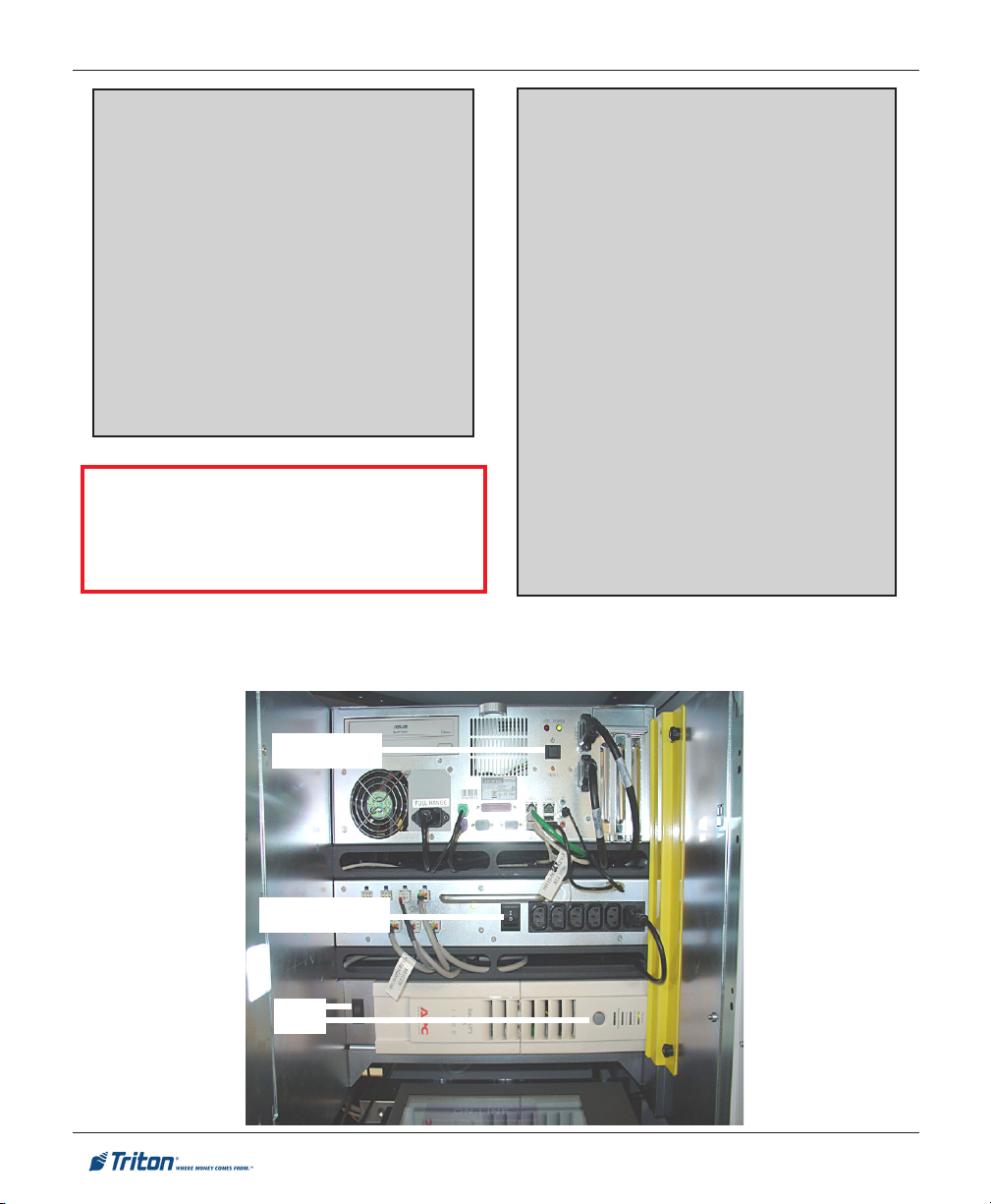
5. Open the top right rear service door. Power up the units Uninterrupted Power Supply (UPS),
Power Supply, and Computer.
For European applications, the power supply cord must conform to the following specifications:
1. Two-conductor with physical earth
2. IEC 320 molded connector on one end
3. Certified for country of installation.
4. Rated minimum H05VV-F with minimum
5. Maximum length: 3 meters.
POWER SUPPLY CORD
SPECIFICATIONS
ground.
and molded plug on the other end.
0.75 mm2 (except where specific
countries require 1.0 mm2) conductors.
Computer
Power supply
UPS
54
Page 55

FT7000XP - SITE PREPARATION AND INSTALLATION GUIDE
THIS PAGE INTENTIONALLY LEFT BLANK
55
Page 56

ENVELOPE SUPPLY UNIT
56
Page 57

FT7000XP - SITE PREPARATION AND INSTALLATION GUIDE
TESTING /ADJUSTING FOR ENVELOPE T HICKNESS
The optional Envelope Depository Unit (EDU) contains an Envelope Transport Mechanism, Shutter Assembly, and an Envelope Deposit Bin (secure). The Envelope Supply Unit holds approximately 200 envelopes. When loading envelopes, alternate every 50-100 with the flaps UP. For example, load 50 with flaps up
facing Left, then next 50 with flaps facing Right. The envelope size requirements are as follows:
tnemeriuqeReziSepolevnE
s
htgneL htdiW ssenkcihT
muminiM]"19.5[mm051]"57.3[mm59
mumixaM]"6.9[mm442]"52.4[mm801
TEST DISPENSING / RETRACTING ENVELOPES
After installation is complete, it is recommended that you test and verify that the unit dispenses and
accepts only one (1) envelope at a time. To perform an operational check, the unit must be powered up and
you have access to Management functions:
]"72.[mm7
)mm1.832xmm8.401(epolevne01#asiezisdednemmoceR:etoN
Open the upper left rear cabinet door and pull the Envelope Depository slide tray out fully.
Following the instructions on inserting envelopes (label on unit) , load twenty-five (25) envelopes
(flaps up) into the supply unit bin.
Access Management functions and from the Main menu screen select DIAGNOSTICS > ENVELOPE
DEPOSITORY > ENVELOPE DISPENSE AND RETRACT TEST. The test dispenses an envelope and then automati-
cally retracts it into the depository storage bin (normal operation). Note: With the depository unit tray
extended out, the envelopes will fall on the floor. DO NOT refill supply bin with these envelopes.
After the test is complete, press <1> to repeat. Perform this test a minimum of five (5) times.
If one (1) envelope has repeatedly been dispensed/retracted, the check is complete. If the envelope
has double-fed OR has not fed, proceed with the next procedures.
57
Page 58
ENVELOPE SUPPLY UNIT
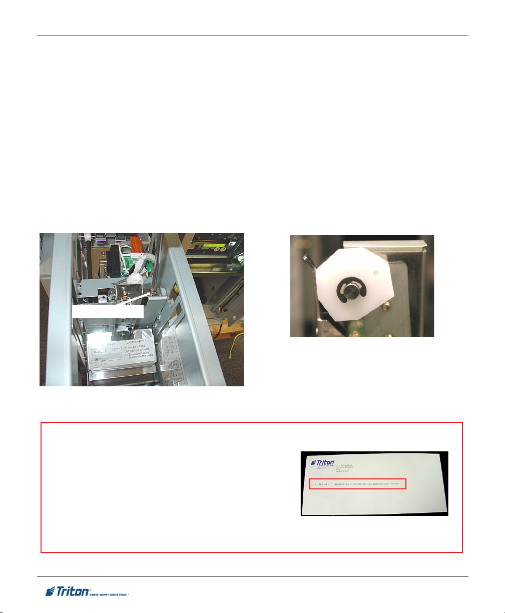
ADJUSTING THE ENVELOPE T HICKNESS
With a phillips screwdriver, loosen the screw shown and slide the plate back.
Rotate the cam shown clockwise one (1) position if the envelope was double-feeding. If the
envelope was not feeding, rotate the cam one (1) position counterclockwise.
Slide the plate back and secure screw. Perform the DISPENSE AND RETRACT T EST again, minimum five
(5) times.
If the test was not successful (one envelope picked/retracted) each time the test was performed,
loosen the screw again and move the cam one (1) position again in the same direction. Resecure screw and
perform the test again (minimum five (5) times).
Keep repeating these steps until the unit successfully dispenses/retracts one (1) envelope each time.
Loosen screw
Turn cam clockwise one position if
Turn cam counterclockwise one
RECOMMENDATION
THE ENVELOPE DEPOSITORY STAMPS DEPOSITED ENVELOPES
WITH
IDENTIFYING DATA. THIS DATA IS STAMPED APPROXI-
MATELY IN THE MIDDLE OF THE ENVELOPE AS SHOWN IN THE
FIGURE
AT RIGHT. IF YOUR ENVELOPES HAVE A LOGO/GRAPHIC
THAT
IS AT OR NEAR THE CENTER, THIS DATA WILL PRINT OVER
THIS
AND MAY MAKE IDENTIFICATION HARD TO DETERMINE.
RECOMMEND EITHER MOVING YOUR LOGO UP TO THE COR-
NERS OR USE PLAIN ENVELOPES.
58
envelopes double-feeding.
position if not feeding.
Page 59

FT7000XP - ALARM PANEL DIAGRAM
59
 Loading...