


TSDCO-E1
1
INSTALLATION AND OPERATING INSTRUCTIONS
Cyclone
SERIES
ELECTRIC CONVECTION OVENS
Models: TSCO-E1 and TSDCO-E1
INTENDED FOR OTHER THAN HOUSEHOLD USE
RETAIN THIS MANUAL FOR FUTURE REFERENCE
OVEN MUST BE KEPT CLEAR OF COMBUSTIBLES AT ALL TIMES
FOR YOUR SAFETY: Do not store or use gasoline or other flammable vapors or
liquids in the vicinity of this or any other appliance.
WARNING: Improper installation, adjustment, alteration, service or maintenance
can cause property damage, injury or death. Read the Installation, Operating and
Maintenance Instructions thoroughly before installing or servicing this equipment.
WARNING: Initial heating of oven may generate smoke or fumes and must be
done in a well-ventilated area. Overexposure to smoke or fumes may cause
nausea or dizziness.
This equipment has been engineered to provide you with year round dependable service when used
according to the instructions in this manual and standard commercial kitchen practices.
P/N 21709212 09/12
TRI-STAR MANUFACTURING
729 3
RD
Avenue
Dallas, TX 75226
Phone : +1 (714) 424-9380
Fax : +1 (714) 424-9385 www.tri-starmfg.com Web
Toll Free : +1 (866) 782-7462

2
CONTENTS
I. INSTALLATION INSTRUCTIONS
SECTION ITEM PAGE
A Receiving ..................................................... 2
B Set-up/Mounting .......................................... 2
C Installation with Casters ............................... 3
D Location & Minimum Clearances ................. 3
E Electrical Connections ................................. 4
F Flue Connection Ventilation ......................... 5
G Initial Cleaning ............................................. 5
H System Check – Rotary Controls ................. 5
II. OPERATING INSTRUCTIONS
SECTION ITEM PAGE
A General Instructions...................................... 6
B Operation Sequence for Rotary Controls ...... 6
1. Cook Only ................................................. 6
2. Timed Cooking ......................................... 6
3. Cook & Hold.............................................. 6
4. Steam Injection (Optional) ........................ 7
5. Oven Cool Down....................................... 7
SECTION ITEM PAGE
C C&H-3 Push Button Control ............................. 8
D Cleaning .......................................................... 12
E Servicing .......................................................... 13
1. Open Rack Ass’y Instructions .................... 13
2. Stacking Instructions .................................. 14
3. Leg Assembly Instructions ......................... 14
4. Helpful Hints ............................................... 15
5. Troubleshooting Chart ................................ 15
F Wiring Diagrams
1. Single Phase 208V/240V
Wiring Diagram (Dial Control) .................... 16
2. Three Phase 208V/240V
Wiring Diagram (Dial Control) .................... 16
3. Single Phase 208V/240V
Wiring Diagram (Push-Button Control) ....... 17
4. Three Phase 208V/240V
Wiring Diagram (Push-Button Control) ....... 17
5. Three Phase 230V/400V (Export Only)
Wiring Diagram (Dial Control) .................... 18
G Warranty .......................................................... 20
I. INSTALLATION INSTRUCTIONS
A. RECEIVING
Read the notice on the outside carton regarding damage in transit. Damage discovered after opening
the carton is “CONCEALED DAMAGE.” Carrier must be notified immediately to send an inspector and
to furnish forms for claims against the carrier.
When the oven arrives, it should consist of:
• A crate or carton containing your new oven (two for a stacked unit).
• A carton containing four 31" legs with mounting hardware (set of four 6" legs is supplied for stacked
installations).
• A carton containing a Flue Adapter and a Draft Hood. Optional: for Direct Venting (Not available for
European Community Countries).
B. SET UP / MOUNTING
NOTE:
This appliance must be installed by competent personnel in accordance with the rules in force.
Your oven will be packed sitting on its bottom. The skid may be left under the oven for convenience in
further handling. Unpack carefully, avoiding damage to the Stainless Steel front and/or trim. If
concealed damage is found, follow the instructions detailed in Section A (Receiving). Keep the area
around the ovens free and clear of combustible materials. Do not store any materials on top of or under
any oven. The provision of adequate air supply to your oven for ventilation is essential. As a minimum,
observe the clearances detailed in Section D (Location). Provide adequate ventilation and make up air

3
in accordance with local codes. Servicing your oven is done through the front control panel and right
side access cover. Ensure that these areas are kept unobstructed for easy access.
For a single unit: Refer to Figure 4
(1) Tilt Oven over to left-hand side and attach two 31” legs on the right-hand side with four 3/8-16” bolts
and washers. Tighten firmly.
(2) Using proper lifting equipment, lift up the left-hand side and attach two 31” legs on the left-hand side
the same way.
For a stack of two ovens: Refer to Figure 3
(1) Remove flue from top oven and replace with flue-adaptor supplied in the stacking kit.
(2) Tilt lower unit over to the left side and position two 6" legs on the right side (one for front and one for
back), secure in place by using 4 bolts (3/8-16) per leg. Tighten firmly.
(3) Using proper lifting equipment, lift up the left side of the unit and attach the other two legs in the
same way.
(4) Using the lifting equipment, raise the top oven to proper height and slide onto top of the bottom
oven. Line up sides and front and fasten to each other at the rear of the units by using a mounting
bracket supplied in the stacking kit.
To assemble an open rack stand: Refer to Figure 2
(1) Loosen 12 bolts (attaching 31” legs) slightly.
(2) Remove 4 inner bolts, 1 from each of the 4 legs, place top right angle and top left angle underneath
and tighten these 4 bolts.
(3) Insert “Open Rack Shelf” and tighten into place with eight 3/8-16 screws, washers and nuts.
(4) Position “Rack Supports” and tighten in place using 4 each of flat washers and 5/16-18 Hex Nuts.
C. INSTALLATION WITH CASTERS (OPTIONAL):
Four casters (two with wheel brakes) and the mounting hardware are packed and included in the
shipment if ordered. Install casters with wheel brakes on the front of the unit. Installation must conform
to UL 197: Electrical Supply Connections for Permanently Connected Appliances. It requires that
permanently connected appliances with casters be provided with a means for securing the appliance to
the building structure to limit the movement of the appliance.
Oven Restraint: When casters are installed on either a single or double unit, a fixed restraint must be
used to limit the movement of the appliance without depending on or transmitting stress to the electrical
conduit. The restraint (a heavy-gauge cable) should be attached to the rear legs of the oven on which
casters are mounted. If disconnection of the restraint is necessary, the restraint must be reconnected
after the oven has been repositioned in its permanent location. The appliance shall be installed using
flexible conduit.
D. LOCATION AND MINIMUM CLEARANCES:
Move the oven to its final location keeping the minimum clearance from the back of the oven to the wall.
This clearance is necessary for safe operation and to provide proper air flow.
MINIMUM CLEARANCES FROM COMBUSTIBLE AND NONCOMBUSTIBLE CONSTRUCTION
Under Ventilation Hood
RIGHT WALL 1"
LEFT WALL 1"
REAR WALL 3"
4
Suitable for installation on combustible floor when installed with legs or casters
provided.
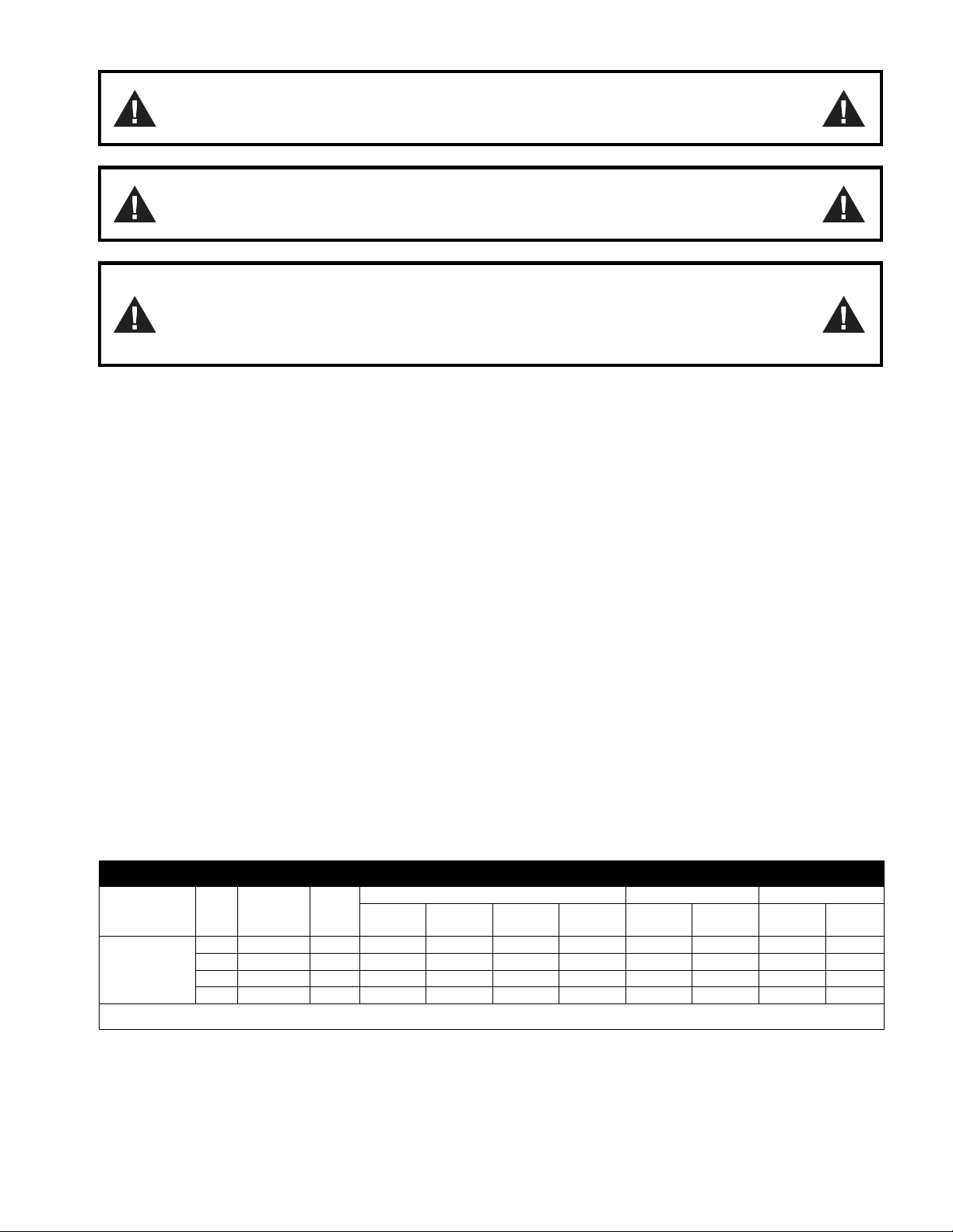
CAUTION: Do not set the oven with its back flat against the wall. It will not
operate properly unless there is at least three inches breathing space behind the
oven
NOTICE:
Local codes regarding installation vary greatly from one area to
another. The National Fire Protection Association, Inc., states in it’s NFPA 96
latest edition that local codes are “authority having jurisdiction” when it comes to
requirements for installation of equipment. Therefore, installations should comply
with all local codes.
E. ELECTRICAL CONNECTION:
Install according to the spacing requirements listed in the installation section of this manual. We
strongly recommend having a competent professional install this equipment. A licensed electrician
should make the electrical connections and connect power to the unit. Local codes should always be
used when connecting these units to electrical power. In the absence of local codes, use the latest
version of the National Electrical Code.
Note: For supply connections use No. 6 AWG wires suitable for at least 90°C.
The oven, when installed, must be electrically grounded in accordance with local codes and/or the latest
edition of the National Electrical Code ANSI/NFPA No. 70 in the USA (Canadian Electrical Code CSA
Standard C22.1, Part 1 in Canada).
In Europe, the appliance must be connected by an earthen cable to all other units in the complete
installation and, thence, to an independent earth connection in compliance with EN 60335-1 and/or
local codes.
Electrical power is to be supplied to the oven(s) by means of hard wiring, which is to be performed by a
qualified licensed electrician.
a) Adequate means must be provided to limit the movement of the appliance without depending on
or transmitting stress to the electrical conduit.
b) The location(s) where restraining means are to be attached to the appliance shall be specified.
c) The appliance shall be installed using flexible conduit.
TSCO-E1, TSDCO-E1
Model KW Voltage Phase
Amps
Motor
-
50hz
Motor
-
60hz
Line 1 Line 2 Line 3 N
RPM
(Low)
RPM
(High)
RPM
(Low)
RPM
(High)
BCO-E,
GDCO-E
10.5
208
1
48
48
-
-
725
1425
850
1725
10.5
208
3
30
30
28
-
725
1425
850
1725
10.5
220
-
240
1
44
44
-
-
725
1425
850
1725
10.5
220
-
240
3
26
26
2
4
-
725
1425
850
1725
Each oven requires separate electrical connections
Normal factory connections are made for 208 V. A.C. or 208/240 V.A.C., 60 Hz.
This unit is provided with a permanently lubricated electric motor. A wiring diagram may be found on the
back of the service panel on the right-hand side and also in this manual.
5
F. FLUE CONNECTION VENTILATION:
Installation under ventilation hood (standard):
Local inspectors and ventilation specialists should be consulted so that the design and the installation of
the hood conform to local/municipal codes. In the U.K., follow ventilation requirements as detailed in
B.S. 5440.
NOTE: DO NOT PUT A DAMPER IN THE FLUE AND DO NOT CONNECT A BLOWER DIRECTLY
TO THE FLUE.
If the flue runs directly to the free air outside the building, use a wind deflector or a UL listed vent cap at
the end of the pipe. Termination of the vent must be at least two feet above the highest part of the roof
within ten feet. REF: AGACATALOG NO. Xh0474.
G. INITIAL CLEANING:
Always clean equipment thoroughly before first use. Clean the protective oil from the metal parts and
interior of baking chamber with a solution of washing soda or the other grease dissolving material.
H. SYSTEM CHECK- ROTARY CONTROL (standard):
(1) Open the oven door.
(2) Turn Selector Switch to “HI.” The green indicator light near Selector Switch and oven light will
illuminate.
(3) Close the door. Oven lights will go off and fan will run. Make sure fan is rotating clockwise
looking from front.
(4) Press Oven Light switch. Oven light will go on and will go off as switch is released.
(5) Turn the thermostat knob. The amber indicator light near the thermostat will illuminate and the
heating elements will come on.
(6) Turn the timer knob past 10 minutes and back to 2 minutes. At the end of 2 minutes the buzzer
will sound. Reset by turning to “0.” All settings below 10 minutes require turning past 10
minutes and then back to the time required.
(7) Open the oven doors. Oven lights will go on and elements and fan will go off.
(8) Turn Selector Switch to “Cool Down” position. The fan will run to cool down the oven.
(9) Turn Selector Switch to “0” position.
(10) Close the oven doors.
NOTE: WITH THE DOORS CLOSED, THE POWER SWITCH “ON” AND THE SELECTOR SWITCH
IS IN ANY POSITION OTHER THAN “0”, THE OVEN WILL START HEATING AS SOON AS THE
SET TEMPERATURE IS HIGHER THAN THE OVEN TEMPERATURE.
THERMOSTAT INDICATOR LIGHT GOES OUT WHEN OVEN REACHES SET TEMPERATURE AND
COMES ON WHEN OVEN IS HEATING UP.
IN THE EVENT OF POWER FAILURE, THE OVEN WILL NOT OPERATE.
PROGRAMMING MENUS: See Operating/Programming Instruction Booklet for
Programmable Oven Control with Bakers Pride Software for Cyclone Series
Convection Ovens supplied with this option.

6
II. OPERATING INSTRUCTIONS
A. GENERAL INSTRUCTIONS:
(1) This equipment has an Electronic Temperature Control.
(2) Due to increased efficiency of this oven, the temperature of standard recipes may be reduced
50°F (30°C).
(3) Always load each shelf evenly. Space pans away from each other and from sides and back of
oven to allow maximum air flow between them.
(4) Large tempered glass windows and interior lights allow a close check on the product making it
unnecessary to frequently open the doors. Products cook faster in a convection oven as
compared to a conventional oven. Depending on the product and the type of pans used, time
saving may run from 20 percent to as high as 50 percent.
B. OPERATION SEQUENCE ROTARY CONTROL:
Cook only rotary control:
(1) Close the oven doors.
(2) Turn Selector Switch to “HI” or “LO” position. The indicator light near the Selector Switch will be
illuminated.
(3) Turn the thermostat knob to the desired cooking temperature.
(4) Upon reaching the set temperature, the indicator light near the thermostat will go out.
(5) Load the oven with product to be cooked.
(6) Remove the product from the oven when done.
Timed cooking rotary control:
(1) Close the oven doors.
(2) Turn Selector Switch to “HI” or “LO” position. The indicator light near the Selector Switch will be
illuminated.
(3) Turn the thermostat knob to the desired cooking temperature.
(4) Upon reaching the set temperature, the indicator light near the thermostat will go out.
(5) Load the oven with product to be cooked.
(6) Turn the timer knob to the desired bake time and timer will start counting down.
(7) When timer reaches zero, a buzzer will sound.
(8) Turn the timer knob to “O” position.
(9) Remove the product from the oven.
NOTE: TIMER DOES NOT CONTROLTHE OVEN.
Cook and Hold Rotary Control:
(1) Close the oven doors.
(2) Turn Selector Switch to “HI” or “LO” position. The indicator light near the Selector Switch will be
illuminated.
(3) Turn the thermostat knob to the desired cooking temperature.
(4) Upon reaching the set temperature, the indicator light near the thermostat will go out.
(5) Load the oven with product to be cooked.
(6) Turn the timer knob to the desired bake time and timer will start counting down.
(7) When timer reaches zero, a buzzer will sound.
(8) Turn the Timer knob to “O” position.
(9) Turn the thermostat knob to the desired hold temperature.
(10) Remove the product from the oven when done.

7
Optional steam injection Rotary control:
The solenoid valve for steam injection is mounted behind the service panel on the right-hand side of the
unit. The electronic timer is preset at the factory. A ¼” copper tubing is provided on the Solenoid Valve
for water hookup with a compression fitting. After the water hookup is made, make sure that there are
no leaks. For steam injection, press the Steam switch momentarily.
NOTE: DO NOT USE STEAM INJECTION AT TEMPERATURES BELOW 275°F (135°C).
Oven cool down Rotary control:
To cool down the oven to a lower desired temperature, follow the steps detailed below.
(1) Open the oven doors.
(2) Turn Selector Switch to “oven cool down” position. Fan will now operate and cool down the
oven.
(3) When the oven has cooled down to the desired temperature, turn the Selector Switch to “O”
position. Close oven doors.
 Loading...