

Page 1

Owner’s Manual
®
SmartOnline
Single-Phase Rackmount Online UPS Systems
with Built-in LCD Monitoring & Control Screen
Not suitable for mobile applications.
SUINT1000LCD2U
(Series Number: AGPS8294)
1. Overview 2
Parts List 2
Additional Accessory Options 2
Model Specific Accessories 2
2. Important Safety Instructions 2
3. UPS Circuit Block Diagram 3
4. Installation 4
Rack Mounting 4
Tower Mounting 5
Smart Battery Communications 6
Connection
5. Basic Connections 7
and Start-Up
Quick Start Guide 7
6. Features 9
Front Panel Controls, LEDs and 9
LCD Screen
Rear Panel Features 9
SUINT1500LCD2U
(Series Number: AGPS8295)
Quick
Start Guide—
Page 7
SUINT2200LCD2U
(Series Number: AGPS7958)
7. Operations 11
LCD Front-Panel Display and Controls 11
Front Panel Button Functions 12
Home Screen Layout 12
Power Strategy Selection Options 13
Front Panel LCD Selection and 14
Configuration Options
Configuring External Battery Packs 18
8. Optional Connections 20
9. Troubleshooting and Event Log 23
10. Internal Battery Replacement 25
11. Storage and Service 26
12. Product Registration and 27
Regulatory Compliance
Español 28
Français 55
Русский 82
Deutsch 109
SUINT3000LCD2U
(Series Number: AGPS7959)
SU3000LCD2UHV
(Series Number: AGPS8296)
NOTE: External battery pack options require configuration using front panel LCD interface or via Tripp Lite’s EXTERNAL BATTERY CONFIGURATION software.
WARRANTY REGISTRATION
Register your product today and be
automatically entered to win an ISOBAR
surge protector in our monthly drawing!
tripplite.com/warranty
1111 W. 35th Street, Chicago, IL 60609 USA • tripplite.com/support
Copyright © 2019 Tripp Lite. All rights reserved. SmartOnline® is a trademark of Tripp Lite. For latest updates, please visit tripplite.com
1
Page 2
Overview
Tripp Lite SmartOnline Rackmount UPS Systems with interactive LCD interface feature online, double-conversion UPS protection with fulltime sinewave output and zero transfer time suitable for all advanced networking applications. Each system provides long running battery
support with optional extended-run and Web communications ability. Built-in interfaces include USB, RS-232 serial and Emergency
Power Off (EPO). The interactive front panel LCD screen provides detailed UPS status, preset and control options. Optional max efficiency
and auto-adaptive power strategy options enable high-efficiency operation with reduced power consumption and BTU heat output.
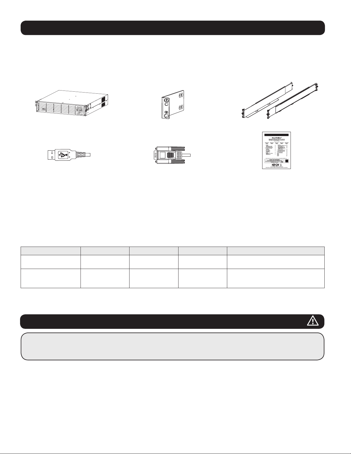
Parts List
UPS System Bolt-on Mounting Ears (2) 4-Post Rail Kit
Owner’s Manual
Owner’s Manual
USB Cable RS-232 Cable Owner’s Manual
Additional Accessories (All Models; Optional)*
• SNMPWEBCARD: Internal network interface card for SNMP/Web control and monitoring
• WEBCARDLX: Web Management Accessory Card
• 2POSTRMKITWM: Supports rackmount UPS and battery packs in 2-post rackmount or wall-mount configurations
• 2-9USTAND: Supports rackmount UPS and battery packs in upright tower configuration
* Select models are also shipped with optional Input/Output adapter cables.
Model Specific Accessories (Optional)*
UPS Model SUINT1000LCD2U SUINT1500LCD2U SUINT2200LCD2U SUINT3000LCD2U / SU3000LCD2UHV
“SMART” External
Battery Packs**
“NON-SMART” External
Battery Packs**
*Visit the specification page for your UPS system at tripplite.com for detailed extended runtime data and additional accessory options.
** For External battery configuration, see the Operations section for options and configuration method. SMART battery packs are automatically detected by the UPS.
BP24V36-2US BP36V27-2US BP48V27-2US BP72V18-2US
BP24V15RT2U (limit 1)
BP24V28-2U (limit 1)
BP24V70-3U
BP36V15-2U (limit 1)
BP36V42-3U
BP48V24-2U (limit 1)
BP48V60RT3U
BP72V15 (limit 1)
BP72V28RT3U
Important Safety Instructions
SAVE THESE INSTRUCTIONS
This manual contains instructions and warnings that should be followed during the installation, operation and storage of all
Tripp Lite UPS Systems. Failure to heed these warnings may affect your warranty.
UPS Location Warnings
• Install your UPS indoors, away from excess moisture or heat, conductive contaminants, dust or direct sunlight.
• For best performance, keep the indoor temperature between 0º C and 40º C.
• Leave adequate space around all sides of the UPS for proper ventilation.
• Do not mount unit with its front or rear panel facing down (at any angle). Mounting in this manner will seriously inhibit the
unit’s internal cooling, eventually causing product damage not covered under warranty.
2
Page 3
Important Safety Instructions
UPS Connection Warnings
• Connect your UPS directly to a properly grounded AC power outlet. Do not plug the UPS into itself; this will damage the UPS.
• Do not modify the UPS's plug, and do not use an adapter that would eliminate the UPS’s ground connection.
• Do not use extension cords to connect the UPS to an AC outlet. Your warranty will be voided if anything other than Tripp Lite surge
protectors are used to connect your UPS to an outlet.
• If the UPS receives power from a motor-powered AC generator, the generator must provide clean, filtered, computer-grade output.
• The mains socket outlet that supplies the UPS should be near the UPS and be easily accessible.
• To remove AC voltage from the UPS, pull the plug from the socket outlet.
Equipment Connection Warnings
• Use of this equipment in life support applications where failure of this equipment can reasonably be expected to cause the failure of
the life support equipment or to significantly affect its safety or effectiveness is not recommended.
• Do not connect surge protectors or extension cords to the output of your UPS. This might damage the UPS and may affect the surge
protector and UPS warranties.
• Connect the UPS to an outlet that is adequately protected against excess currents, short circuits and earth faults, as part of the
building installation. The outlet protection for the UPS should be in series with the mains input.
• To reduce the risk of fire, connect only to a circuit that has branch circuit over current protection with an ampere rating in accordance
with the National Electrical Code® (NEC®), ANSI/NFPA 70 or your local electrical code. In Europe, the circuit breaker must meet the
IEC/EN 60934 standard and have a contact air gap of at least 3 mm. The recommended circuit breaker rating for building installation
is 240V/20A and must meet the rated short circuit capacity of at least 1 KA.
Battery Warnings
• Batteries can present a risk of electrical shock and burn from high short-circuit current. Observe proper precautions. Do not dispose of
the batteries in a fire. Do not open the UPS or batteries. Do not short or bridge the battery terminals with any object. Unplug and turn
off the UPS before performing battery replacement. Use tools with insulated handles. There are no user-serviceable parts inside the
UPS. Battery replacement should be performed only by authorized service personnel using the same number and type of batteries
(Sealed Lead-Acid). The batteries are recyclable. Refer to your local codes for disposal requirements or visit tripplite.com/
UPSbatteryrecycling for recycling information. Tripp Lite offers a complete line of UPS System Replacement Battery Cartridges
(R.B.C.).Visit Tripp Lite on the Web at tripplite.com/support/battery/index.cfm to locate the specific replacement battery for your UPS.
Note: For External battery configuration, see the Operations section for options and configuration method. SMART BATTERY PACKS are automatically detected by the UPS.
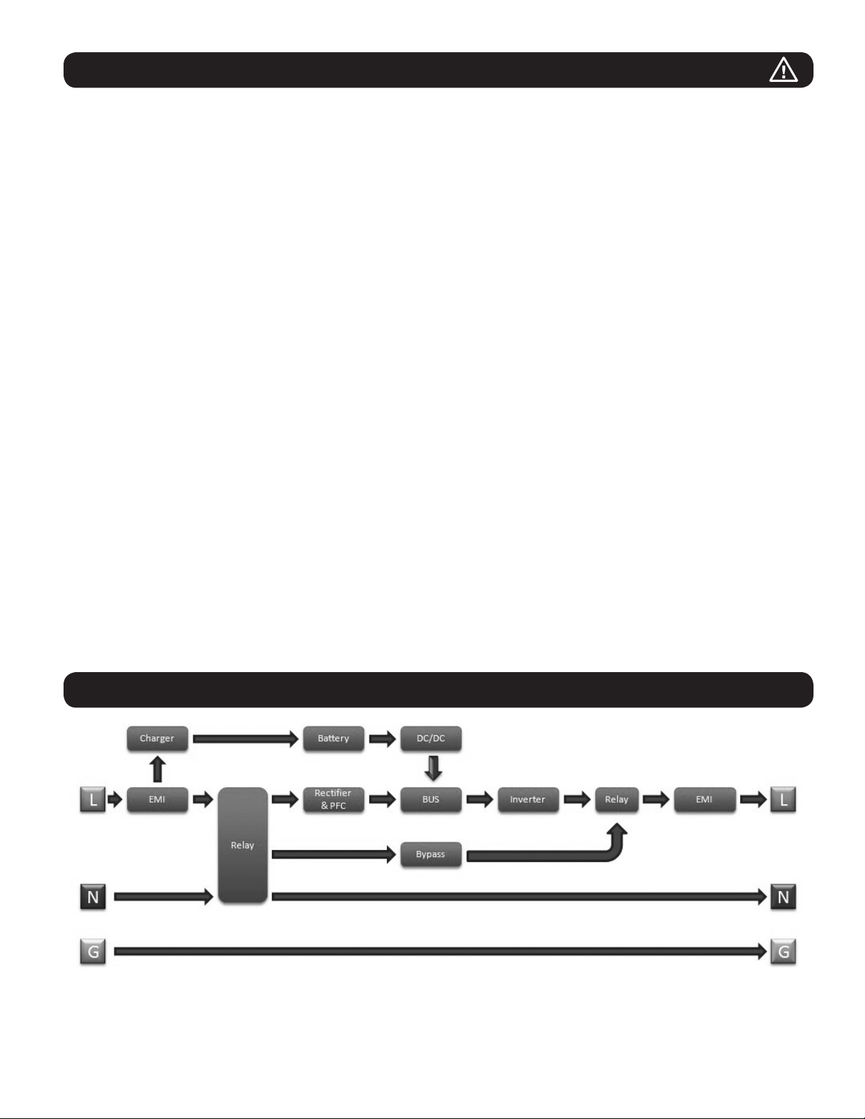
UPS Circuit Block Diagram
3
Page 4
Installation
Rack Mounting
Mount your equipment in either a 4-post or 2-post rack or rack enclosure. The user must determine the fitness of hardware and
procedures before mounting. If hardware and procedures are not suitable for your application, contact the manufacturer of your rack or
rack enclosure. The procedures described in this manual are for common rack and rack enclosure types and may not be appropriate for
all applications.
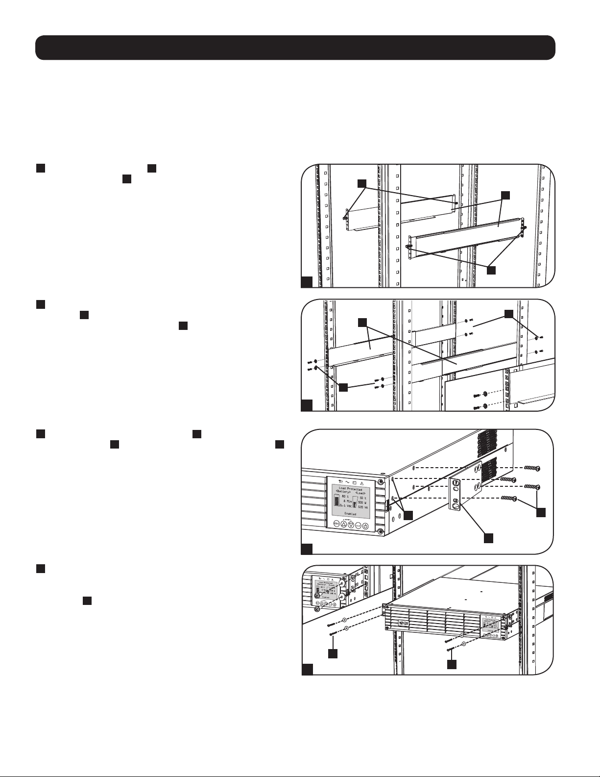
4-Post Mounting
1
The included plastic pegs A will temporarily support the empty
rackmount shelves B while you install the permanent
mounting hardware. Insert a peg into the third hole from the
top on the front end of each bracket. On the rear end, insert a
peg into the center hole. (Each front bracket has 6 holes and
each rear bracket has 5 holes.) The pegs will snap into place.
After installing the pegs, expand each shelf to match the depth
of your rack rails. The pegs will fit through the square holes in
the rack rails to support the shelves. Refer to the rack unit
labels to confirm that the shelves are level in all directions.
Note: The support ledge of each shelf must face inward.
2
Remove the pegs at the front end of each bracket. Secure the
shelves B to the mounting rails permanently using the
included screws and cup washers C as shown. Place 2 screws
at the front of each rail (4 total) and 2 screws at the back of
each rail (4 total). Tighten all screws before proceeding.
Note: The rear pegs can be left in for installation, but the front ones must be
removed before the bracket is secured by screws.
WARNING!
Do not attempt to install your UPS until you have
inserted and tightened the required screws. The plastic
pegs will not support the weight of your UPS.
1
2
A
B
A
C
B
C
3
Attach your UPS’s mounting brackets D to the forward
mounting holes E of the UPS using the included hardware F.
The mounting bracket “ears” should face forward.
E
D
3
4
With the aid of an assistant (if necessary), lift your UPS and
slide it into the shelves. Attach the UPS mounting brackets to
the forward mounting rails with user-supplied screws and
washers G. Tighten all screws securely.
G
4
G
2-Post Mounting
If you mount 2U UPS models in 2-post racks, they require the addition of a Tripp Lite 2-Post Rackmount Installation Kit (model:
2POSTRMKITWM, sold separately). See Installation Kit owner’s manual for installation procedure.
F
4
Page 5
Installation
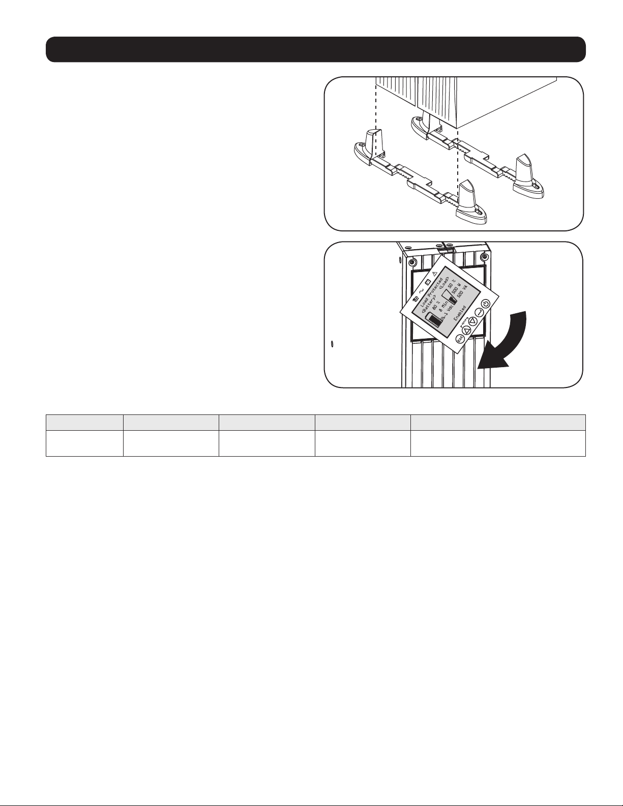
Tower Mounting
Your UPS can be mounted in an upright tower position with
optional base stands sold separately by Tripp Lite (model:
2-9USTAND). When mounting the UPS on adjustable base stands,
make sure that the control panel is toward the top. The control
panel may be rotated to make it easier to read. Remove the 4
front screws from the front panel and take it off. Pinch the tabs
located on the sides of the LCD panel, and then rotate it. Replace
the front panel and secure it. Front panel setup should be
operated by service personnel only.
WARNING!
All UPS systems are extremely heavy. Use caution when
lifting and mounting. User must properly stabilize the UPS
when lifting and mounting.
UPS Model SUINT1000LCD2U SUINT1500LCD2U SUINT2200LCD2U SUINT3000LCD2U / SU3000LCD2UHV
UPS Dimensions
(H x W x D)
Operating Altitude: 0 to 3000 m
8.6 x 43.8 x 39.6 cm 8.6 x 43.8 x 49.6 cm 8.6 x 43.8 x 49.6 cm 8.6 x 43.8 x 61.6 cm
5
Page 6
2
1
Installation
Smart Battery Communications Connection
Your UPS supports automatic detection of its internal batteries and up to 6 external SMART BATTERY PACKS. Prior to powering up the
UPS from AC mains power, you must connect the internal SMART BATTERY communication cable in the following manner:
1
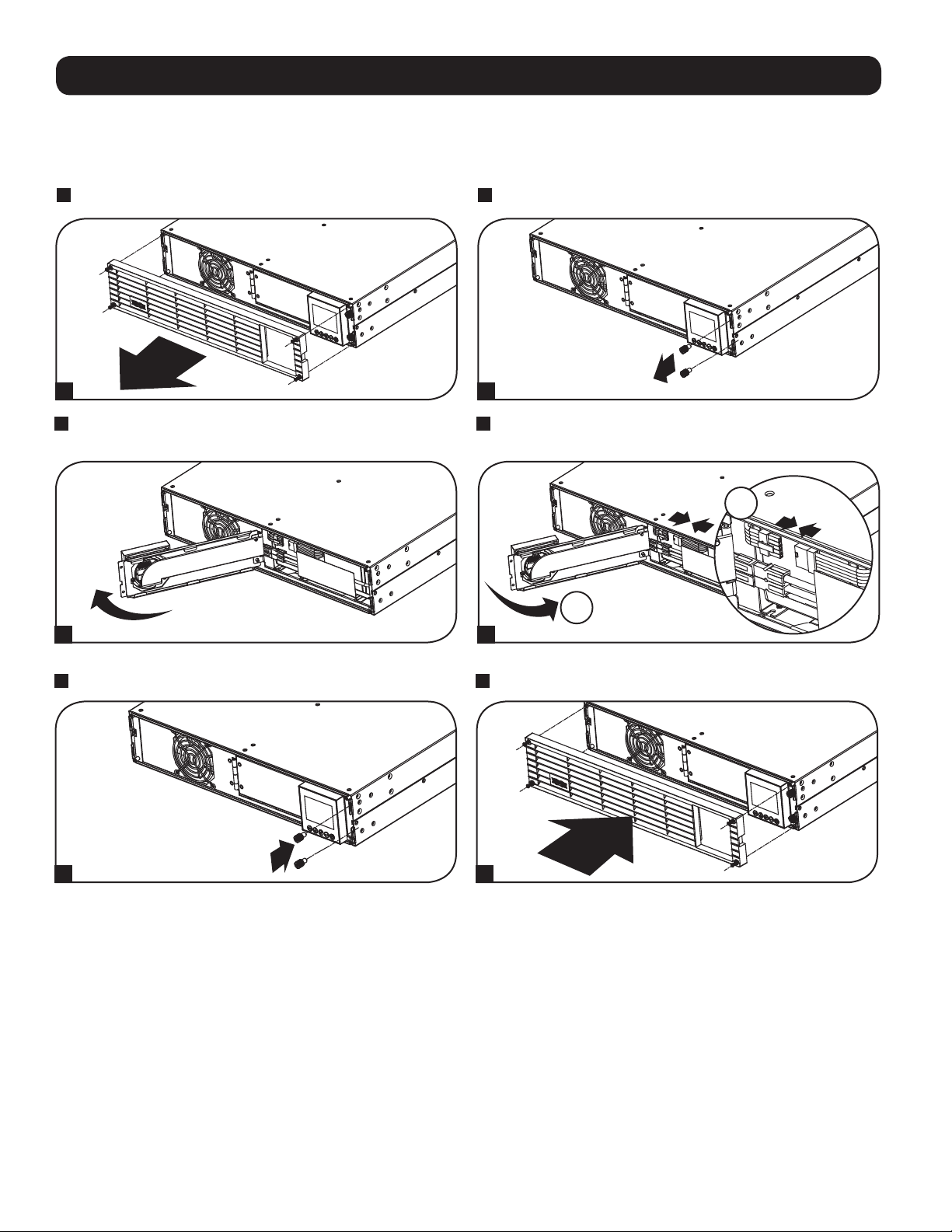
Remove the 4 front screws from the front bezel and take it off.
1 2
2
Loosen the 2 screws securing the front plate.
3
Open the front plate.
3
5
Tighten the 2 screws to secure the front plate.
4
Connect the SMART BATTERY communication cable. Close the
front plate.
4
6
Replace the 4 front screws to secure the bezel.
5 6
EXTERNAL BATTERY CONFIGURATION NOTE
If external battery packs are to be used with this UPS, install them following the mounting/installation documentation included with each
battery pack. External battery pack installation requires the UPS be configured one of two ways:
1. Via the UPS front panel LCD interface
2. Via Tripp Lite’s EXTERNAL BATTERY CONFIGURATION software
This UPS is factory programmed with discharge curves and charging profiles for external battery pack configurations accessible using the
UPS front panel LCD interface. Additional battery pack options using larger or multiple external battery packs are also supported, but
require configuration using Tripp Lite’s EXTERNAL BATTERY CONFIGURATION software and a serial port connection to the UPS.
6
Page 7
Basic Connection and Start-Up
Quick Start Guide - First Time UPS Power-On
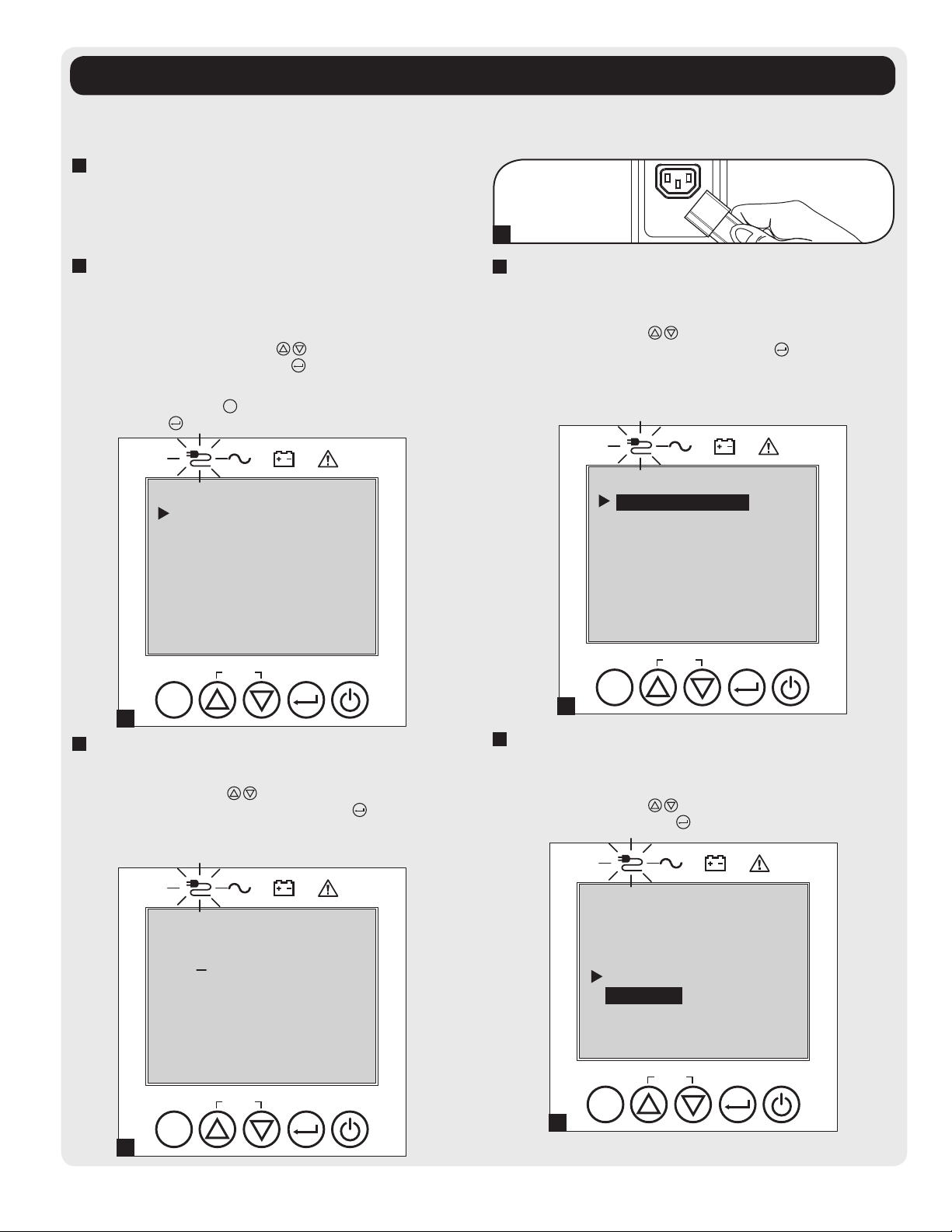
1
Plug your UPS line cord into an electrical outlet
Your UPS must be connected to a dedicated circuit of sufficient
amperage.
Refer to the rating table labelled on the UPS for more details.
1
2
Select your Language
When your UPS is plugged in for the first time, the INPUT AC
LED will light up and the front panel LCD screen will request a
language selection.
Using the UP / DOWN buttons
preference, then press the NEXT
The interface will confirm your selection and provide options to
go back (press BACK
(press NEXT
ESC
) or to go to the next step
).
, select your language
button.
Language
English
Back Next
SETUP
ESC
2
4
Select your Password
Next, the UPS will prompt you to pick the desired PASSWORD.
Using the UP / DOWN
your desired password and press the NEXT
advance to the second digit. Repeat for digits 2 through 4.
Note: To quickly set the password to “0 0 0 0” press the NEXT button 4 times.
buttons, select the first digit of
button to
3
Select your Power Strategy
Next, the UPS will prompt you to pick the desired POWER
STRATEGY.
Using the UP / DOWN
STRATEGY preference and press the APPLY
See the Power Strategy Selection Options and UPS
Operating Modes sections under the Operations section for
operating characteristics of each power strategy.
buttons, select your POWER
button.
Power Strategy
Auto-Adaptive
Max Efficiency
Max Quality
Freq. Regulation
Freq. Conv. To 60Hz
Freq. Conv. To 50Hz
Back Select Apply
SETUP
ESC
3
5
Select UPS Output Voltage
Next, the UPS will prompt you to select the desired OUTPUT
VOLTAGE.
Using the UP / DOWN
voltage, then select APPLY
buttons, select the UPS output
.
Password Setup
0 0 0 0
Back Select Next
SETUP
ESC
4
Output Voltage
200 Vac
208 Vac
220 Vac
230 Vac
240 Vac
Back Select Apply
SETUP
ESC
5
7
Page 8
Basic Connection and Start-Up
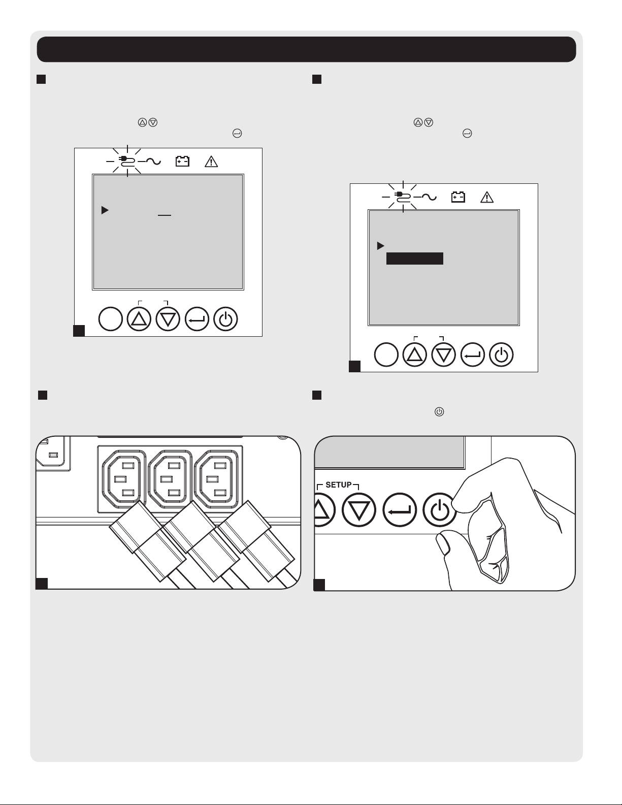
6
Select UPS Battery Age Alert
Next, the UPS will prompt you to select the timing of the
BATTERY AGE ALERT.
Using the UP / DOWN
battery age alert in months, then press APPLY
buttons, select the timing of the
.
Batt Age Alert
Months:36
Back Select Apply
SETUP
ESC
6
7
Select Audible Alarm ENABLE / DISABLE status
Next, the UPS will prompt you to select the alarm ENABLE /
DISABLE status.
Using the UP / DOWN
DISABLE status, then press APPLY
Note: Disabling the alarm prevents the audible alarm from sounding during
power failures and UPS fault conditions only. The alarm will still “chirp” to
confirm operator input via the front panel LCD navigation buttons when the alarm
is set to disable.
buttons, select the alarm ENABLE /
.
Audible Alarm
Enabled
Disabled
Back Select Apply
SETUP
ESC
7
8
Plug your equipment into the UPS
Your UPS is designed to support network, server and computer
equipment only.
Your model and outlet may differ.
8
9
Turn your UPS on
Press and hold the POWER
release as the alarm begins to sound.
button for 3 seconds and
9
The UPS will then go through a series of diagnostic checks
before turning on output power. Once the UPS reports the
operating status of NORMAL / LOAD PROTECTED with the
configured POWER STRATEGY enabled, your UPS can
immediately be put into service to provide reliable protection
from a wide variety of power problems.
8
Page 9
Features
Before installing and operating your UPS, familiarize yourself with the locations and function of the features of each component.
Front Panel Controls, LEDs and LCD Screen
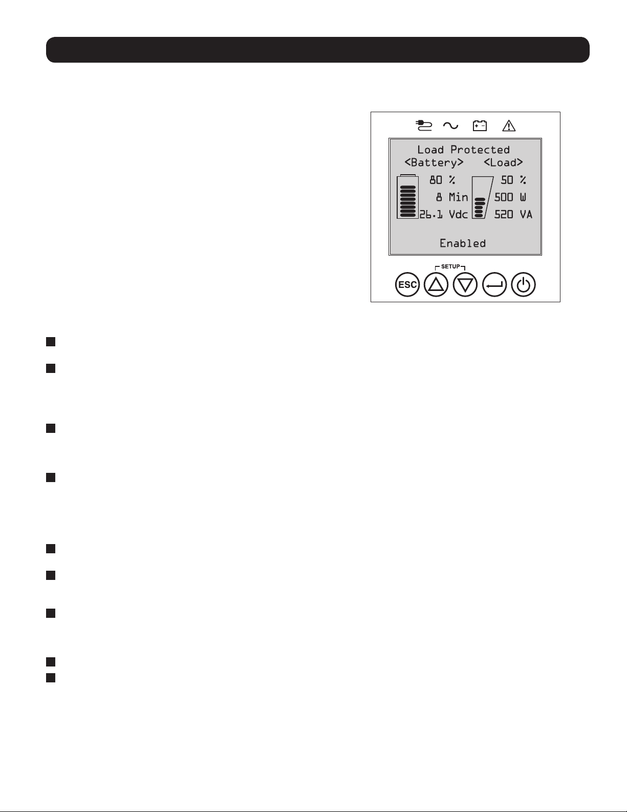
The graphical LCD on the front panel contains a wide range of UPS
operating conditions and diagnostic data. It also displays UPS
settings and options when viewing the UPS setup screens. The five
buttons below the LCD can be used to navigate the various
information, configuration and UPS control screens by following the
on-screen prompts and selection options. Additional LED indicators
above the LCD screen also provide at-a-glance status of AC input
source, availability of output, battery status, and warning/fault status.
See Operations section for detailed descriptions of LCD functions,
buttons and LEDs.
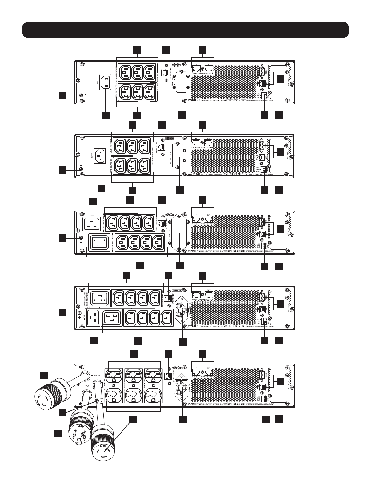
Rear Panel Features
1
Input Cord Connection: This connects to AC power via a user-supplied cord with country-specific plug or permanently attached
power cord.
2
AC Receptacles (varies by model): These output receptacles provide connected equipment with pure sine-wave AC output during
normal operation and battery power during blackouts and severe brownouts. Power provided by these outlets is filtered to protect
connected equipment against damaging surges and line noise. The receptacles are divided into numbered load banks, as labeled on
the unit. Using PowerAlert software and cabling, load banks one and two may be individually turned off and on from a remote
location, allowing users to reset or reboot connected equipment.
3
Telephone or Telephone/Network Protection Jacks: These jacks protect your equipment against surges over a telephone line or
telephone/network data line. Connecting your equipment to these jacks is optional. Your UPS will work properly without this
connection.
Note: Not compatible with PoE (Power Over Ethernet) applications.
4
Communications Ports (USB or RS-232): These ports connect your UPS to any workstation or server. Use with Tripp Lite’s
PowerAlert Software and included cables to enable your computer to automatically save open files and shut down equipment during
a blackout. Also use PowerAlert Software to monitor a wide variety of AC line power and UPS operating conditions. Consult your
PowerAlert Software manual or contact Tripp Lite Customer Support for more information. The 9-pin RS-232 port also supports drycontact communications. See USB & RS-232 Serial Communications in the Optional Connections section for installation
instructions.
5
EPO (Emergency Power Off) Port: Your UPS features an EPO port that may be used to connect the UPS to a contact closure
switch to enable emergency inverter shutdown. See Optional Connections section for details.
6
Accessory Slot: Remove the small cover panel from this slot to use optional accessories to remotely monitor and control your UPS.
Visit tripplite.com to see a full list of accessories, including the WEBCARDLX for remote control and UPS monitoring, as well as a
wide variety of network management and connectivity products.
7
External Battery Pack Connector (configuration varies by model): Your UPS supports the use of optional Tripp Lite external
battery packs for additional runtime. See Model Specific Accessories section under the Overview section for compatible models
and limitations and Configuring External Battery Packs section under Operations section for configuration instructions.
Note: External battery pack options require configuration using front panel LCD interface or via Tripp Lite’s EXTERNAL BATTERY CONFIGURATION software.
8
Ground Screw: Use this to connect any equipment that requires a chassis ground.
9
External Battery Detection Port: For external batteries with communication built-in, plugging the battery communication cable
into this port will allow the UPS to automatically detect the external battery.
9
Page 10
Features
SUINT1000LCD2U
8
SUINT1500LCD2U
8
SUINT2200LCD2U
2 9
1
1
1
2
2
2
2
9
9
7
7
3
4
5 6
3
4
5
6
3
8
SUINT3000LCD2U
8
SU3000LCD2UHV
2
2
2
1 5
2
2 3
7
9
7
9
3
4
5
6
4
6
4
8
6
2
1
10
57
Page 11
Operations
This section explains how to use your Tripp Lite Online UPS System, including front-panel LCD operation, operating modes, UPS startup
and shutdown, transferring between modes, setting power strategy, and configuring bypass settings, load segments and battery settings.
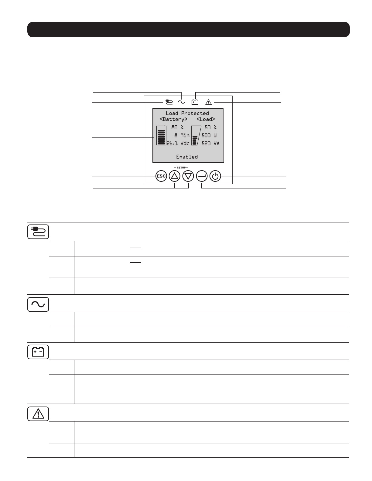
LCD Front-Panel Display and Controls
There is a 5 button graphical LCD screen with additional LED indicators on the front of the UPS that provides information on UPS status,
load level information, event information, measurements, settings and a wide variety of UPS configuration and power strategy options.
AC Output LED (Green) Battery Mode LED (Yellow)
AC Input LED (Green)
LCD Screen
Fault LED (Red)
Escape
Page Up/Page Down
On/Off
Enter
LED Front Panel Indicators
There are 4 LEDs above the front panel LCD screen that offer information on AC INPUT, BYPASS, AC OUTPUT, BATTERY MODE and UPS
FAULT status.
AC INPUT indicator
On AC input is available AND AC input is WITHIN the configured ECONOMY / BYPASS mode range.
When this LED is ON SOLID, AC input is of adequate quality for UPS operation in BYPASS or ECONOMY MODE.
Flashing AC input is available AND AC input is OUTSIDE the configured BYPASS mode range.
When this LED is ON FLASHING, AC input is not of adequate voltage or frequency for UPS operation in BYPASS or
ECONOMY MODE.
Off AC input is NOT available.
When this LED is OFF, AC input is not available.
AC OUTPUT indicator
On UPS AC output is ON
UPS output is available at the UPS output receptacles.
Off UPS AC output is OFF
UPS AC output is not available.
BATTERY MODE indicator
On UPS is running in battery mode
UPS batteries are discharging as the UPS runs in battery mode. Also lights momentarily during self-test operation.
Flashing UPS is running in battery mode - Low battery warning
UPS batteries are discharging as the UPS runs in BATTERY mode and are becoming low. The indicator will flash at
2 second intervals to report LOW BATTERY and 0.5 second intervals to report BATTERIES ARE NEAR FULLY
DISCHARGED and the UPS is near shutdown.
UPS FAULT indicator
On UPS is experiencing a pre-defined fault state
See front panel display for explanation of error state or code information. See on-screen instructions and manual
for troubleshooting tips.
Off Normal
UPS is not reporting fault conditions when this indicator is OFF.
11
Page 12
Operations
Front Panel Button Functions
There are 5 front panel buttons that offer UPS control and configuration options. To navigate the various information, configuration and
UPS control screens, use the 5-button front panel interface and follow the on-screen prompts and selection options.
Power On / Off Button: This control offers three main functions: Power-On, Power-Off and Clear UPS Fault.
To turn the UPS ON into a protected operating mode, press and hold this button for 3 seconds as the UPS is connected to
input AC power. Release the button when the alarm begins to sound and the UPS will startup into the last configured power
strategy.
To “cold start” the UPS on into battery mode during power failure conditions, press and hold this button for 3 seconds.
Release the button when the alarm begins to sound and the UPS will startup in battery mode.
To turn the UPS OFF as it’s running in battery or protected mode, press and hold this button for 3 seconds. Release the
button when the alarm begins to sound. The UPS will turn off AC output. Once AC output is off, disconnect input power to the
UPS and the UPS will power off completely.
To CLEAR UPS FAULT, press and hold this button as directed on-screen for 3 seconds. The UPS will clear the fault conditions
and return to standby or bypass mode.
ENTER Button: This control is used to make selections, confirm options and move forward to the next selection as the UPS is
configured in setup mode. Press this button as directed on-screen in Setup mode to Enter, Confirm or Move Forward in the
configuration process.
UP / DOWN Buttons: These controls offer two main functions: “Up” and “Down” directional control, plus enter / exit setup
mode (when pressed simultaneously). These buttons are used to navigate setup-mode menu options and scroll up or down to
view screen contents as necessary.
To ENTER or EXIT UPS SETUP MODE, press these two buttons simultaneously for 3 seconds. Release the button when the
alarm begins to sound. The UPS will automatically enter setup mode if both buttons are pressed during LCD display modes.
The UPS will automatically exit setup mode if both buttons are pressed as the UPS runs in UPS setup mode.
ESCAPE Button: This control offers three main functions: Alarm Cancel, Clear Fault and Back / Cancel operations.
To CANCEL UPS ALARM, press this button. If a new alarm condition occurs, the alarm will sound again.
To CANCEL or GO BACK ONE LEVEL, press this button as directed on-screen in Navigation and Setup modes.
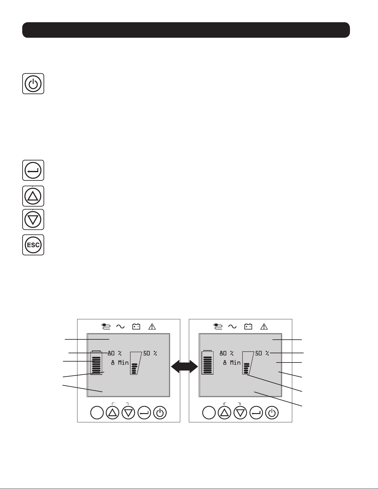
Home Screen Layout
The UPS front panel LCD screen is set up to provide continuous UPS operating information using NORMAL MODE and BATTERY MODE
home-screens that continuously report operating mode, protection status, power strategy and a number of battery and load-level
operating parameters.
Normal Mode Home Screens
Operating Mode Protection Status
Online
<Battery> <Load>
Battery Charge % Output Load %
Battery Charge
“Bars”
Battery Voltage
Power Strategy
0.5 KW
0.5 KVA26.1VDC
Max Efficiency
SETUP
ESC
Load Protected
<Battery> <Load>
0.5 KW
0.5 KVA26.1VDC
Enabled
SETUP
ESC
Output Load
(Kilowatts)
Output Load
(KVA)
Output Load
“Bars”
Power Strategy
(Continued)
12
Page 13

Operations
Power Strategy Selection Options
Tripp Lite SmartOnline LCD UPS systems offer several built-in power strategy options that enable the UPS to optimize performance to
meet user needs for MAXIMUM POWER QUALITY, MAXIMUM EFFICIENCY, and FREQUENCY REGULATION or FREQUENCY CONVERSION
operation. An additional AUTO-ADAPTIVE power strategy combines the benefits of high-efficiency and maximum power quality. Each
power strategy option enables the UPS to automatically shift between specific operating modes as power and UPS status dictates.
Available power strategy options include:
• Auto-Adaptive Power Strategy enables the UPS to automatically switch between ONLINE MODE and ECONOMY MODE as dictated by
the quality and reliability of UPS input power. If the UPS does not experience a power failure in a week’s time (not including UPS selftest) the UPS will automatically switch to ECONOMY MODE. If a power failure occurs, the UPS will maintain output in BATTERY MODE.
When power is restored, the UPS will repeat the cycle by running in ONLINE MODE until there are no power failures for one week’s
time.
• Max-Efficiency Power Strategy enables the UPS to run continuously in ECONOMY MODE anytime incoming AC power is within the
configured bypass low/high voltage range. If UPS input voltage is outside the configured bypass range, the UPS will automatically
switch to ONLINE MODE until AC input voltage is restored within the configured bypass voltage range. This is similar to Auto-Adaptive
Power Strategy, except transfer to ECONOMY MODE is immediate as voltage levels recover. There is no one-week time period of power
failure free operation required in order for the UPS to return to ECONOMY MODE operation.
• Max-Quality Power Strategy enables the UPS to run continuously in ONLINE MODE the entire time incoming AC power is within the
range for online mode operation. The UPS will remain operating continuously in Online Double-Conversion mode, providing the highest
quality output power with zero transfer time. Auto-bypass mode is available during UPS failure modes when AC input is within the
bypass range.
• Frequency Regulation Power Strategy is similar to Max-Quality Power Strategy, except the UPS will actively regulate output
frequency within +/-0.05Hz of the 50 or 60Hz nominal frequency measured on startup. The UPS will remain operating continuously in
Online Double-Conversion mode, providing the highest quality output power with zero transfer time. Auto-bypass mode is available
during UPS failure modes when AC input is within the bypass range.
• Frequency Conversion to 60Hz & Frequency Conversion to 50Hz Power Strategies are similar to Max-Quality power strategy,
except the UPS will actively regulate output within +/-0.05Hz of the 50Hz (Freq. Conv. to 50Hz setting) or 60Hz (Freq. Conv. to 60Hz
setting). Auto-bypass is not available in FREQUENCY CONVERSION mode. Typical applications include converting 50 to 60Hz (or 60 to
50Hz) for sensitive electronic devices.
Note: Maximum power supported in Frequency Regulation/Conversion modes is derated by 30%.
UPS Operating Modes
Tripp Lite SmartOnline UPS systems are able to automatically switch between operating modes under conditions specified in the
configured Power Strategy. The UPS continuously indicates status using front panel LEDs and the interactive LCD viewing screen.
• Battery Mode is the UPS system’s automatic response to power failures and voltage variations outside of the online voltage range. In
BATTERY MODE, the UPS maintains sine wave AC output power from battery reserves. Once power is restored, the UPS will return to
the protected operating mode as dictated by the configured power-strategy and input power conditions.
• Online Mode (also known as ONLINE, DOUBLE CONVERSION MODE) offers the highest level of UPS equipment protection. In ONLINE
MODE, the UPS actively regenerates power from AC to DC, then from DC to AC to provide continuously regulated AC output within 2%
of the selected nominal output voltage with zero transfer time as the UPS switches between ONLINE and BATTERY modes.
• Economy Mode offers power saving operation with the highest level of UPS operating efficiency. In ECONOMY MODE, the UPS saves
energy by turning off the online, double-conversion process whenever input power is within the ECONOMY MODE voltage range. If line
voltage falls outside of the ECONOMY MODE, the UPS will respond by automatically switching to ONLINE MODE until line voltage
recovers.
• Frequency Regulation Mode gives the UPS the ability to correct frequency variations present on UPS input power. See Power
Strategy Selection Options section for details.
• Frequency Conversion to 60Hz and Frequency Conversion to 50Hz Modes give the UPS the ability to convert frequency from
50Hz to 60Hz (or 60Hz to 50Hz). See Power Strategy Selection Options section for details.
Note: Maximum power supported in Frequency Regulation/Conversion modes is derated by 30%.
• Bypass Mode offers filtered and unregulated power to connected equipment.
13
Page 14

Operations
Power Strategy Operating Features and Supported UPS Operating Modes
The configured UPS Power Strategy provides a framework for UPS operation as it switches between operating modes as dictated by
power events and UPS status. Each Power Strategy offers a unique set of operating parameters that the UPS adheres to in order to
meet user preferences for high-performance or high efficiency. Additional frequency regulation and conversion options are also available
for advanced applications. The chart below lists the UPS operating modes supported for each Power Strategy option.
UPS OPERATING MODES
UPS automatically switches operating modes as dictated by the configured power strategy, current
power and UPS status conditions.
Support for
ONLINE MODE
AUTO ADAPTIVE
UPS runs continuously in
ECONOMY MODE after
running in ONLINE MODE
for one continuous week
without a power failure.
MAX. QUALITY
UPS runs in ONLINE MODE
continuously to maintain
the highest quality output
power for connected
equipment.
MAX. EFFICIENCY
UPS runs in ECONOMY
MODE full time when input
is within the bypass range.
FREQUENCY
REGULATION
UPS regulates output
to within +/-0.05Hz of
nominal.
FREQUENCY
CONVERSION to 60Hz
UPS converts 50Hz input
to 60Hz.
(+/-0.05Hz)
FREQUENCY
CONVERSION to 50Hz
UPS converts 60Hz input
to 50Hz.
POWER STRATEGY SELECTION OPTIONS
Your power strategy selection enables the UPS to switch between operating modes
as described
(+/-0.05Hz)
* LCD displays FREQUENCY REGULATION as the operating mode with derating information.
** LCD displays FREQUENCY CONVERSION as the operating mode with derating information.
YES. When input is within
the ONLINE voltage range,
but outside the BYPASS
voltage range, and after
AC power is restored.
YES. When input is within
the ONLINE voltage range.
YES. When input is within
the ONLINE voltage range,
but outside the BYPASS
voltage range.
YES. When input is within
the ONLINE voltage
range.*
YES. When input is within
the ONLINE voltage
range.**
YES. When input is within
the ONLINE voltage
range.**
Support for
ECONOMY MODE
YES. When input is within
the ECONOMY MODE
voltage range and there
are no power failures for
one week.
NO. YES. YES. In the event of
YES. When input is within
the ECONOMY MODE
voltage range.
NO. YES. YES. In the event of
NO. YES. NO.
NO. YES. NO.
Support for
BATTERY MODE
YES. YES. In the event of
YES. YES. In the event of
Support for
AUTO-BYPASS
UPS inverter fault while
input voltage is within the
BYPASS voltage range.
UPS inverter fault while
input voltage is within the
BYPASS voltage range.
UPS inverter fault while
input voltage is within the
BYPASS voltage range.
UPS inverter fault while
input voltage is within the
BYPASS voltage range.
14
Page 15

Operations
Front Panel LCD Selection and Configuration Options
MAIN MENU / SUBMENU DISPLAY / SETTING OPTIONS DISPLAY / SETTING DESCRIPTION
STATUS
Load Status • Load level (%, kW, kVA, A, PF)
• Available capacity (%, kW, kVA)
In/Out Status • Input voltage & frequency (Vac, Hz)
• Output voltage & frequency (Vac, Hz)
• Load Group1 (On, Off)
• Load Group2 (On, Off)
Energy Status • Efficiency (%)
• Avg. Power (kw/hr.)
• Configured power strategy
Int. Batt. Status • Installed (mm/dd/yyyy)
• Expires (mm/dd/yyyy)
Ext. BP. Status • Battery pack model & serial number
• Installed (mm/dd/yyyy)
• Expires (mm/dd/yyyy)
Power Flow Chart • View UPS operational flow chart Displays UPS operating mode in a graphical flow chart.
CONTROL
Start Batt. Test • Initiates a manual battery test Initiates a momentary UPS battery self-test with immediate
Reset Batt. Age • Resets the battery age Resets battery age to today’s date. Use this option after NON-
Reset Fault State • Resets any fault state messages Use this option to clear UPS fault messages.
Auto Batt. Testing • Set regular battery self-test interval
EVENT LOG
On Batt. Events • Event counter
All Events • Event counter (all events)
Reset Batt. Events • Resets battery events only Resets all data in the on-battery events screen set.
Reset All Events • Resets all events Resets all data in the all-events screen set.
SETTINGS
Basic setup
o Disable
o 4 weeks (factory setting)
o 13 weeks
o 26 weeks
(UPS On-battery events only)
• Total minutes (total minutes of
on-battery mode operation)
• Most recent power failure (date)
• Days until battery replacement alert
(days)
• Event details (date, time &
description for the last 20 logged events)
• Most recent event (date)
• Date time log
• Event details (date, time and description
of each logged event)
System
• Current date (display, set date)
• Current time (display, set time)
• Audible alarm (enable, disable)
• Language (select)
Output voltage
• 200
• 208
• 220
• 230
• 240
UPS load percent (%), kilowatt (kW), kilovoltamp
(kVA), amp (A) & power factor (PF).
UPS capacity available in percent (%), kilowatts (kW)
& kilovoltamps (kVA).
Displays UPS input and output status information for input /
output voltage (Vac), frequency (Hz) and outlet group power
status (On/Off) information.
Displays UPS efficiency percentage (%), connected equipment
kilowatt hour consumption (kw/hr.) and configured power
strategy.
Displays internal Replacement Battery Cartridge install date and
user configured expiration date.
Displays external Battery Pack model number & serial number
(Tripp Lite SMART BATTERY PACKS) only, installation date and
user configured expiration date.
Pass/Fail results.
SMART battery replacement.
Use this option to initiate automatic UPS battery testing at
regular intervals.
Displays a summary of all ON-BATTERY events where the UPS
switched to battery mode in response to a protected condition.
Event details lists the last 20 battery events. As additional alerts
occur, the oldest records will be automatically removed.
Displays a summary of all Recorded events. Event details lists
the last 20 events. As additional alerts occur, the oldest records
will be automatically removed.
Displays, sets and resets date, time, audible alarm status and
language settings.
Note: Audible Alarm DISABLE setting prevents power fail and
operating fault alarms only, the UPS will always “beep” to
confirm the UPS is accepting user input from the front-panel
LCD navigation buttons.
Use the SETTINGS / BASIC / OUTPUT VOLTAGE option to display
or set the nominal UPS output voltage (changes take effect on
next restart).
15
Page 16

Operations
MAIN MENU / SUBMENU DISPLAY / SETTING OPTIONS DISPLAY / SETTING DESCRIPTION
SETTINGS
Basic setup
(continued)
Advanced setup
Power strategy:
• Auto-Adaptive
• Max Efficiency
• Max Quality
• Freq. Regulation
• Freq. Conversion to 60Hz
• Freq. Conversion to 50Hz
Battery:
• External battery configuration
o Configure via UPS
o PC configured
o Battery Replacement
• Battery Age Alert
System:
• Display brightness
o High
o Medium (factory setting)
o Low
• Backlight dim: Enter 10-120 seconds
(factory setting is 60 seconds)
• Password: Set your 4 digit password
(factory setting is 0000)
• Factory reset (resets all UPS preferences
to factory settings, including battery
configurations)
In/Out:
• Overload Alert Lvl: Enter a value 5-105%
(factory setting is 100%)
• Conf. Fault Action
(UPS response to fault)
o Go to bypass (factory setting)
o Go to standby
• Bypass Low Limit: Enter a value -5% to
-20% (factory setting is -15%)
• Bypass High Limit: Enter a value +5% to
+20% (factory setting is +10%)
On/Off:
• Cold Start
o Enable (factory setting)
o Disable
• Auto Restart
o Enable (factory setting)
o Disable
• Auto Restart Delay
o Enter: 0 to 60 seconds
(factory setting is 5 seconds)
• Energy Saving
o Enter: 0-100%
o Disable (factory setting)
• Off Mode
o Standby
o Bypass (factory setting)
• Min. Batt to Restart
o Enter: 10-90%
o Disable (factory setting)
Use the SETTINGS / BASIC / POWER STRATEGY option to display
or set the UPS Power strategy.
See Power Strategy Selection Options section under the
Operations section for more info on the available power
strategy options.
Use the SETTINGS / BASIC / BATTERY option to configure the
UPS with external battery packs. Battery replacement option can
be used to update installation date for non-smart external
battery replacement of the same type. Also sets the battery age
alert duration for battery replacement reminder.
See Configuring External Battery Packs section under the
Operations section for information on how to configure external
battery packs.
Use the SETTINGS / ADVANCED / SYSTEM option to set the
display brightness, the display backlight dim time-out, password
or factory reset options.
Use SETTINGS / ADVANCED / IN-OUT for these options:
Sets the UPS output load percentage before an overload alert
is sent.
Sets the UPS response to fault conditions that require the UPS
to exit double-conversion mode. GO TO BYPASS option
maintains AC output (so long as input voltage is within bypass
high/low limits). GO TO STANDBY option causes the UPS to turn
off output AC in response to fault conditions.
Specifies the lowest acceptable input voltage for bypass
operation.
Specifies the highest acceptable input voltage for bypass
operation.
Use SETTINGS / ADVANCED / ON-OFF for these options:
Enabling Cold-start allows the UPS to be manually turned on
into battery mode during a power failure.
Enabling Auto-restart allows the UPS to automatically turn back
on into a protected operating mode when power is restored.
Auto-restart delay forces the UPS to wait 0-60 seconds after
power is restored before automatically restarting.
Requires that Auto-restart when power is restored be enabled.
Energy saving enables the UPS to automatically shutdown when
the output load is less than the selected percentage
continuously for 5 minutes.
Off mode setting of BYPASS allows the UPS to provide
unregulated line power within configured bypass low / high limits
to be available at the output of the UPS when it is turned off.
Minimum battery charge level to restart forces the UPS to wait
until batteries have recharged to the selected percentage before
automatically restarting.
Note: UPS can be manually started using the power button if battery is
below the minimum battery restart threshold.
Requires that Auto-restart when power is restored be enabled.
16
Page 17

Operations
MAIN MENU / SUBMENU DISPLAY / SETTING OPTIONS DISPLAY / SETTING DESCRIPTION
SETTINGS
Advanced setup
(continued)
ABOUT
UPS Information UPS model number, UPS Serial number,
Network ID Web management accessory card firmware,
Firmware UPS firmwares
On battery:
• Low Batt. Alert
o Enter: 10-90% (factory setting is 20%)
• Timed Shutdown
o Enter: 15, 30, 45 sec., 1-30 min.
o Disable (factory setting)
• Low Battery Shutdown
o Enter: 5-100%
o Disable (factory setting)
• On Batt. Beep Delay
o Enter: 0-120 seconds
(factory setting is 5 seconds)
• Shutdown Completion
o Required (factory setting)
o Interrupt OK
USB/DB9 Settings:
• DB9 Settings
o Output pins 1&5
- On battery (factory setting)
- On bypass
- Output on
- Low battery
o Output pins 8&5
- On battery
- On bypass
- Output on
- Low battery (factory setting)
o Input pins 3&9
- Shutdown (factory setting)
- Output off
- Reboot
- Output on
- Power Toggle
• USB signal lost
o Line mode setup
- No action (factory setting)
- Reboot UPS after delay
- Reboot Load1 after delay
- Reboot Load2 after delay
o Battery mode setup
- Run to low battery (factory setting)
- Shutdown after delay
o USB lost timer
- Enter: 10-60 seconds
- Factory setting: 30 seconds
UPS installed date
IPv4 address, IPv6 address, MAC Address
Enables the UPS to send a low-battery alert as batteries
discharge to the selected charge level during a power failure.
Timed shutdown sets the maximum amount of battery runtime
in seconds or minutes the UPS will provide during a power
failure. Use the DISABLE setting for the longest possible battery
runtime.
Low battery shutdown sets the maximum amount of battery
discharge before the UPS shuts down due to low battery. The
setting of DISABLE allows the batteries to discharge to 0%
before shutdown.
The “Beep Delay” setting allows the audible alarm to be delayed
up to 120 seconds to prevent the audible-alarm from sounding
in response to short duration power failures.
The UPS will communicate shutdown messaging to connected
systems prior to UPS shutdown. The setting of INTERRUPT OK
will interrupt shutdown messaging if power is restored after
shutdown messaging is sent.
The UPS will signal the selected condition by shorting pins 1&5
on the DB9 port.
The UPS will signal the selected condition by shorting pins 8&5
on the DB9 port.
The UPS will perform the selected action when pins 3&9 are
shorted on the DB9 port for at least 3.8 seconds.
For the Reboot option (output off for 30 seconds before reboot):
Note the pins must be shorted for at least 3.8 seconds to
perform the reboot. The reboot happens at exactly 3.8 seconds.
If the pins continue to be shorted for more than 3.8 seconds,
no further action should be taken. The UPS takes no action on
release of the short.
The Power Toggle option is intended to keep the unit powered
on whenever the pins are not shorted and powered off whenever
the pins are shorted. Note this input cannot power on the unit
from an off state unless valid AC is applied (this function will not
impose a coldstart). To power on, the pins must be not shorted
for at least 3.8 seconds and AC must be valid. To power off, the
pins must be shorted for at least 3.8 seconds.
The UPS will perform the selected action if the USB signal from
a connected device is lost in line power mode for the duration
selected.
The UPS will perform the selected action if the USB signal from
a connected device is lost in battery power mode for the
duration selected.
This control sets the duration of USB signal loss before the
selected line power-mode / battery power-mode action engages.
UPS installed date is automatically set by the unit after 2 hours
of continuous operation.
17
Page 18
Operations
Configuring External Battery Packs
Tripp Lite SmartOnline INT UPS systems support the connection of external battery packs to enable extended-run UPS operation. In order
for the UPS to provide efficient charging levels and accurate runtime predictions for optimal network runtime prior to sending autoshutdown messaging, external battery packs need to be configured to the UPS upon installation.
There are 3 methods available to configure external battery packs to the UPS, depending on battery pack selected and quantity added to
the UPS. Some battery pack configurations may require the use of more than one configuration method.
EXTERNAL BATTERIES can be
configured to the UPS…
Battery Pack Compatibility
…AUTOMATICALLY
(Using SMART Battery Packs)
UPS supports automatic detection
of up to 6 SMART BATTERY PACKS
connected to the UPS.
…MANUALLY
(Using LCD Screen)
LCD screen can be used to configure NON-SMART BATTERY PACKS
and any additional SMART BATTERY
PACKS beyond the 6 that can be
automatically detected.
…Using EXTERNAL BATTERY
CONFIGURATION SOFTWARE
External Battery Configuration
software can be used to configure
the UPS for any supported quantity
of SMART & NON-SMART external
battery packs.
Tripp Lite SMART Battery Packs include a wired data connection that enables automatic detection and configuration for up to 6 SMART
Battery Packs to the UPS. Tripp Lite Legacy NON-SMART battery packs are also supported for extended runtime applications, but require
user configuration using the front-panel LCD screen or through the use of EXTERNAL BATTERY CONFIGURATION SOFTWARE.
SmartOnline LCD SMART and NON-SMART External Battery Pack Options
SUINT3000LCD2U /
SU3000LCD2UHV
BP72V15 (limit 1)
BP72V28RT3U
Supported “SMART”
BATTERY PACKS
Supported LEGACY
“NON-SMART”
BATTERY PACKS
SUINT1000LCD2U SUINT1500LCD2U SUINT2200LCD2U
BP24V36-2US BP36V27-2US BP48V27-2US BP72V18-2US
BP24V15RT2U (limit 1)
BP24V28-2U (limit 1)
BP24V70-3U
BP36V15-2U (limit 1)
BP36V42-3U
BP48V24-2U (limit 1)
BP48V60RT3U
Configuring SMART and NON-SMART BATTERY PACKS via the front panel LCD screen
Adding up to 6 SMART BATTERY PACKS to the UPS
Each SmartOnline UPS has a designated SMART BATTERY PACK, where up to 6 SMART battery packs can be connected to the UPS for
fully automatic detection and configuration. SMART battery packs include a wired data connection that connects to the UPS Battery Pack
Detection port for automatic recognition and configuration by the UPS.
To configure the UPS for use with up to 6 SMART BATTERY PACKS, just connect the included POWER and DATA cables between the UPS
and the first SMART BATTERY PACK. Then connect the POWER and DATA cables for additional SMART BATTERY PACKS to the one ahead
of it. The UPS will automatically detect and configure up to 6 SMART BATTERY PACKS to the UPS.
Adding more than 6 SMART BATTERY PACKS to the UPS
SmartOnline UPS systems support automatic detection of up to 6 SMART BATTERY PACKS as described above. It is possible to configure
the UPS for more than 6 SMART BATTERY PACKS by configuring all additional SMART PACKS as NON-SMART. When configuring the UPS
with more than 6 SMART BATTERY PACKS, configure BPs #1-6 using the BP Detection port method listed above. Then configure SMART
BATTERY PACKS #7 and above and any other supported battery pack models to be connected as NON-SMART BATTERY PACKS. See the
ADDING NON-SMART Battery Packs section for more information.
Adding BATTERY PACKS to the UPS manually (SMART and NON-SMART battery packs)
If you’re connecting more than the 6 SMART Battery Packs the UPS can automatically detect OR are connecting supported NONSMART
Battery Packs to the UPS, you can configure them via the UPS front panel LCD interface. First, install the Battery Pack power connections
to the UPS as described in the battery pack documentation. Then, using the SETTINGS / BASIC SETTINGS / BATTERY configuration
screens, select the EXTERNAL BATT menu option (see the Front Panel Button Functions and Front Panel LCD Selection and
Configuration Options sections under the Operations section for instructions on accessing this section).
1
From the SETTINGS / BASIC SETTINGS / BATTERY menu, select EXTERNAL BATT, then press
NEXT
.
Battery
18
External Batt
Batt Age Alert
Back Select Next
Page 19
Operations
2
The LCD screen will display the present configuration settings. Press NEXT
configuration.
3
Then select CONFIGURE VIA UPS and press NEXT .
4
The LCD screen will prompt you to move to the next screen where
the SMART and NON-SMART battery packs can be configured.
Then select NEXT
Note: The display will cycle between two screens to show all the text.
…
to edit the
Configure via UPS
Press NEXT to view
detected SMART BPs
(S column) and
specify NONSMART
BP qty (N column).
Back Next
External Batt
Note Presently
configured via UPS
on 04/07/2014
Press Next to change
Back Next
External Batt
Configure via UPS
PC Configured
External Batt
Back Select Next
Configure via UPS
SMART BPs beyond
qty 6 must be
configured as
NONSMART.
Back Next
5
The LCD screen will display the list of supported external battery packs preceded by a column
displaying the number of configured SMART and NON-SMART external battery packs. SMART
BATTERY PACKS detected via the BP DETECTION PORT will already be listed with the appropriate
quantity of 1-6 under the “S” Column of this screen.
To configure NON-SMART batteries and any SMART batteries beyond the 6 that were auto-detected,
use the UP/DOWN
ESC
press BACK
Note: The “S” column displays the number of configured SMART battery packs and the “N” column displays the number of
configured NON-SMART battery packs.
Note: Pressing the UP or DOWN buttons change the “N” column value. Pressing the NEXT button moves the cursor down one
row.
Note: When you reach the last row, NEXT will change to APPLY.
6
After the manually entered NON-SMART battery packs have been
to edit your entry or APPLY to enter the new values.
applied to the UPS, the LCD will report that the change has been
accepted and will suggest you verify that the actual set of external
battery packs match the UPS configuration.
Press NEXT
7
The LCD screen will ask you to press NEXT to enter the battery installation date for manually
to move to the next screen.
and NEXT buttons. After the last battery pack on the list is configured,
Configure via UPS
Change accepted. For
true capacity and
runtime reporting,
verify connected BPs
match configuration
Back Next
configured external battery packs.
The following screen allows you to pick the current date for installation, or allow you to enter an
installation date in the past, in case the BP was added at a previous date.
Configure via UPS
S+N Pack
0 0 BP48V24-2U
0 0 BP48V60RT-3U
0 0 BP484V24-2US
Back Select Next
Configure via UPS
entered.
Back Next
Configure via UPS
Press Next to enter
Battery Installed
Date for manually
added battery packs.
19
Back Next
Page 20
Optional Connections
Your UPS will function properly without these connections.
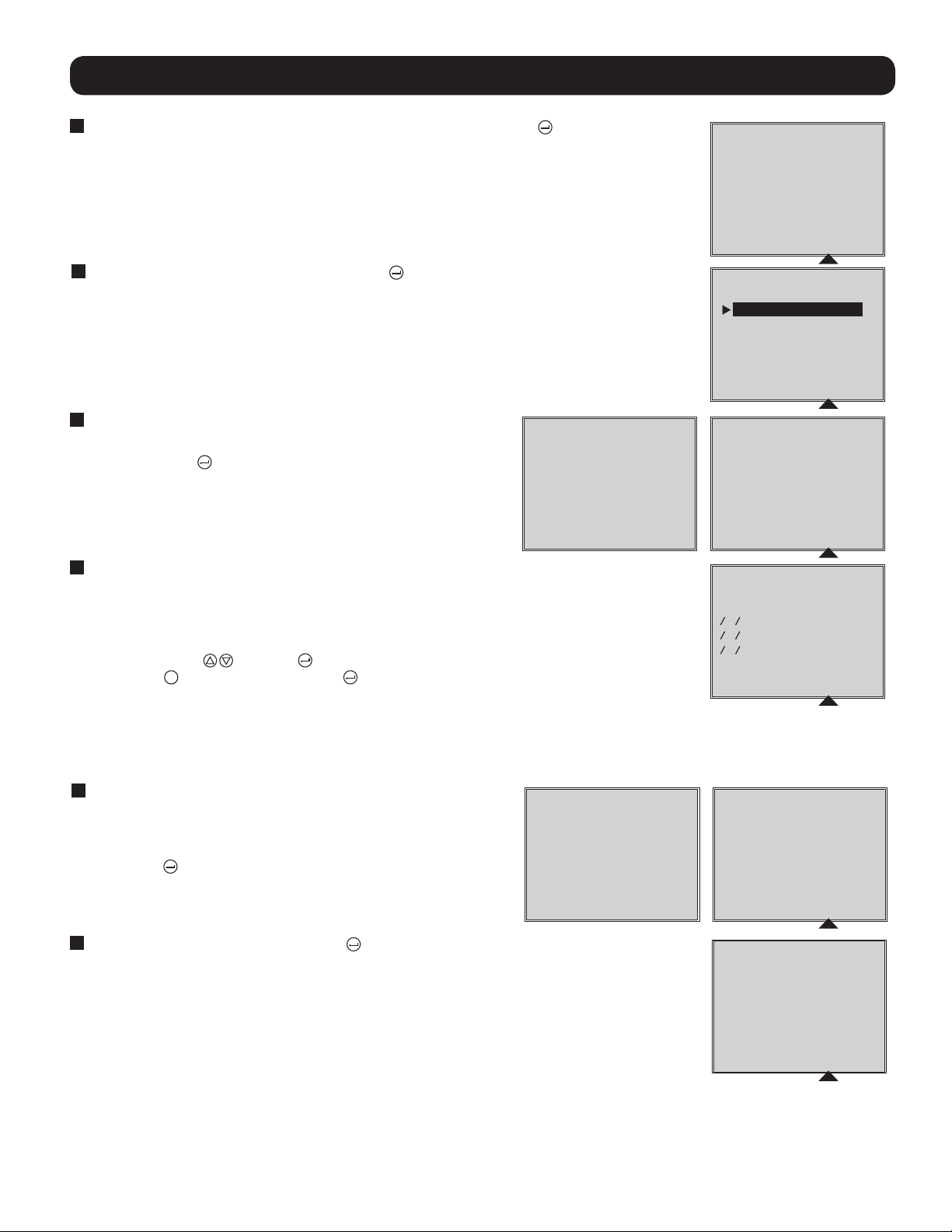
1
Phone Line or Phone/Network Line Surge Suppression
Your UPS has jacks which protect against surges on a phone
line.* Using appropriate telephone or network cords, connect
your wall jack to the UPS jack marked “IN.” Connect your
equipment to the UPS jack marked “OUT.” Make sure the
equipment you connect to the UPS's jacks is also protected
against surges on the AC line.
* Not compatible with PoE (Power Over Ethernet) applications.
Note: Use the same type of connector for the phone line surge suppression input
and output ports.
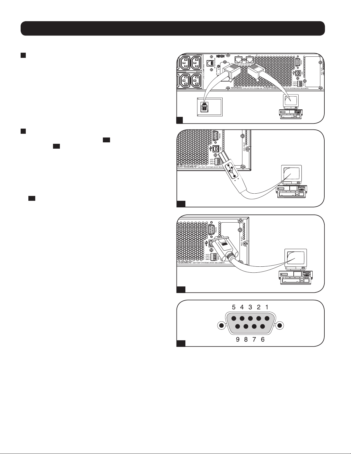
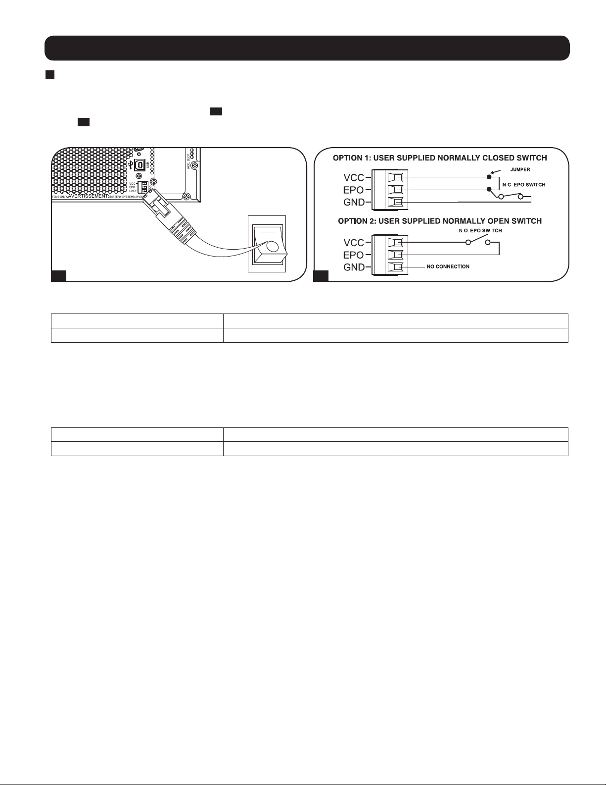
2
USB and RS-232 Serial Communications
Use the included USB cable (see 2a) and/or RS-232 serial
cable (see 2b) to connect the communication port of your
computer to the communication port of your UPS. Install on
your computer the Tripp Lite PowerAlert Software appropriate to
your computer's operating system. Your UPS may feature
additional communications ports; these ports may be
connected to additional computers that have PowerAlert
Software installed. Consult your PowerAlert manual for more
information.
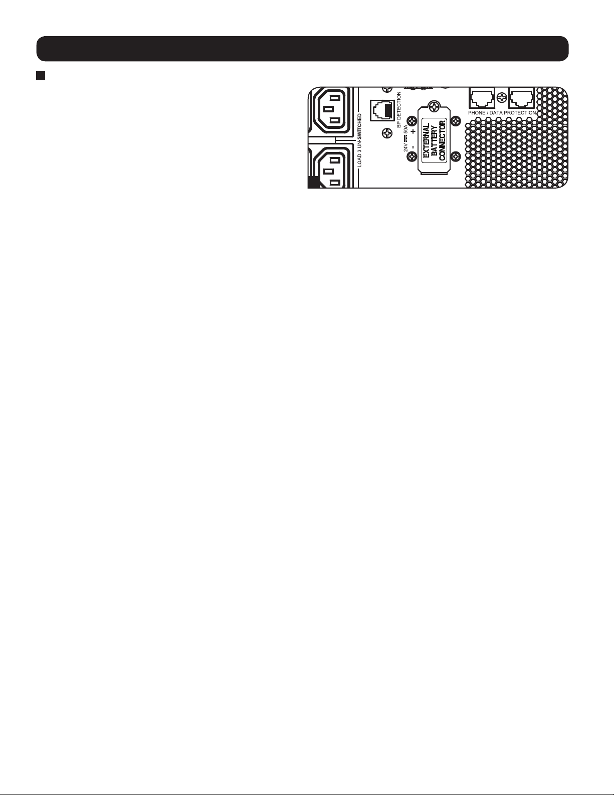
2c
RS-232 Dry contact communications are simple, but some
knowledge of electronics is necessary to configure them. The
RS-232 port’s pin assignments are shown in the diagram. If
the UPS battery is low, the UPS sends a signal by bridging pins
8 and 5. If utility power fails, the UPS sends a signal by
bridging pins 1 and 5. To shut the UPS down remotely, short
pin 3 to pin 9 for at least 3.8 seconds. Additional functions of
these pins can be configured through the LCD or via Web
management accessory card communication.
Your model may differ.
1
Your model may differ.
2a
2b
2c
20
Your model may differ.
Page 21
Optional Connections
3
EPO Port Connection
This optional feature is only for those applications that require connection to a facility’s Emergency Power Off (EPO) circuit. When the
UPS is connected to this circuit, it enables emergency shutdown of the UPS’s inverter and inhibits transfer to internal bypass.
Connect the EPO port of your UPS (see 3a) to a user-supplied normally closed or normally open switch according to the circuit diagram
(see 3b).
Note: If a non-latching EPO switch is used, the EPO must be held for a minimum of 1 second. This does not apply to a latching EPO switch.
4-5
Your model may differ.
3a 3b
UPS state when asserting EPO with valid AC input present:
AC Output LCD Screen Status LEDs Status
Off EPO Active Only AC Input Indicator is On.
To restart the UPS after EPO assertion with valid AC input present:
1. Verify that the EPO assertion has been removed or cleared.
2. Press and hold the POWER ON/OFF button until it beeps. Now the UPS will start back up in one of the pre-configured normal
operating modes.
UPS state when asserting EPO without valid AC input present (Battery Mode):
AC Output LCD Screen Status LEDs Status
Off EPO Active Off
To restart the UPS after EPO assertion without valid AC input present:
1. Verify that the EPO assertion has been removed or cleared.
2. Wait until the LCD completely turns off.
3. Press and hold the POWER ON/OFF button until it beeps. Now the UPS will start back up to Battery Mode.
To restart the UPS after EPO assertion with valid AC input present:
1. Verify that the EPO assertion has been removed or cleared.
2. Wait until the LCD completely turns off.
3. Reapply AC input power, press and hold the POWER ON/OFF button until it beeps. Now the UPS will start back up in one of the
pre-configured normal operating modes.
Note: If AC input power is reapplied before the LCD completely turns off, the UPS will automatically restart to one of the pre-configured normal operating line modes
without using the POWER ON/OFF button.
21
Page 22
Optional Connections
4
External Battery Connection
Check the Model Specific Accessories section under
Overview for compatible battery packs and maximum quantities
for your UPS system. Ensure that your battery pack matches
the voltage listed next to your UPS battery connector. Adding
external batteries will increase recharge time as well as
runtime. See the battery pack owner’s manual for complete
installation and setup instructions. Make sure cables are fully
inserted into their connectors. Small sparks may result during
battery connection; this is normal. Do not connect or
disconnect battery packs when the UPS is running on battery
power.
IMPORTANT! In order for the runtime-remaining LCD and the software information screens to accurately predict runtime
with external battery packs connected, you must configure any connected packs by following the instructions under the
Configuring External Battery Packs section under Operations.
CAUTION: Do not open or mutilate batteries. Released material is harmful to the skin and eyes. It may be toxic. The following
precautions should be observed when working on batteries: Determine if the battery is inadvertently grounded. If inadvertently
grounded, remove the source from ground connection. Contact with any part of a grounded battery can result in electrical shock. The
likelihood of such a shock can be reduced if grounds are removed during installation and maintenance. (This is applicable to
equipment and remote battery supplies that do not have a grounded supply circuit.)
4
Your model may differ.
22
Page 23

Troubleshooting and Event Log
See the chart below for explanation of UPS faults and warnings that can be accessed via the Event Log feature via the LCD screen or
PowerAlert software, as well as suggested solutions for each fault/warning.
Fault/Alarm
Message LCD Screen Message
UPS Internal Errors/Faults:
LCD Header
BUS Start Voltage Low Inverter
Error 1
Inverter error. Restart UPS.
If issue persists, contact
Tripp Lite.
Bus Over Voltage Inverter
Error 2
Inverter error. Restart UPS.
If issue persists, contact
Tripp Lite.
Bus Under Voltage Inverter
Error 3
Inverter error. Restart UPS.
If issue persists, contact
Tripp Lite.
Bus Voltage Unbalance Inverter
Error 4
Inverter error. Restart UPS.
If issue persists, contact
Tripp Lite.
Inverter Soft Start Failed Inverter
Error 5
Inverter error. Restart UPS.
If issue persists, contact
Tripp Lite.
Inverter Over Voltage Inverter
Error 6
Inverter error. Restart UPS.
If issue persists, contact
Tripp Lite.
Inverter Under Voltage Inverter
Error 7
Inverter error. Restart UPS.
If issue persists, contact
Tripp Lite.
Inverter Short Circuit Inverter
Error 8
Inverter output short. Remove
the source of short circuit from
UPS output.
Battery/Charger Related Errors/Faults:
Charger Failure Charger
Failure
If issue persists, contact
Tripp Lite.
Over Charge Over Charge If issue persists, contact
Tripp Lite.
Battery Over Voltage Batt. Over
Voltage
Check battery type used.
If issue persists, contact
Tripp Lite.
Battery Under Voltage Batt. Under
Voltage
Check battery type used.
If issue persists, contact
Tripp Lite.
Bad Battery Bad Battery Restart UPS. If issue persists,
contact Tripp Lite.
Low Battery Low Battery Save your data before UPS
shuts down.
Internal Battery Age
Alert
External Smart Battery
Age Alert
Battery-Age
Alert
Battery-Age
Alert
Internal battery may need
replacement.
External Smart battery:
{SerialNumber} may need
replacement.
External Non-Smart
Battery Age Alert
Smart Batt Changed Smart Batt
Battery-Age
Alert
Changed
External battery may need
replacement.
The number of Smart battery
packs are changed at month/
date/year hr: min. Runtime has
been adjusted. If this change
is unexpected, please check
smart battery communications.
LCD Event Log Display (Event
Type with Date/Time Stamp)
Fault Or
Alarm? Additional Comments
mm/dd/yyyy Inv Err 1 hh:mm UPS fault
mm/dd/yyyy Inv Err 2 hh:mm UPS fault
mm/dd/yyyy Inv Err 3 hh:mm UPS fault
mm/dd/yyyy Inv Err 4 hh:mm UPS fault
mm/dd/yyyy Inv Err 5 hh:mm UPS fault
mm/dd/yyyy Inv Err 6 hh:mm UPS fault
mm/dd/yyyy Inv Err 7 hh:mm UPS fault
mm/dd/yyyy Inv Err 8 hh:mm UPS fault
mm/dd/yyyy Chrg Err 1 hh:mm Warning Charger is not working. No
charge current.
mm/dd/yyyy Chrg Err 2 hh:mm Warning Charger is working but
charge voltage is too high.
mm/dd/yyyy Batt Err 1 hh:mm
Note: If the UPS shuts down from Batt
Err 1, another event, “Batt Err 1 SD”,
is also logged on the event log screen.
mm/dd/yyyy Batt Err 2 hh:mm
Note: If the UPS shuts down from Batt
Err 2, another event, “Batt Err 2 SD”,
is also logged on the event log screen.
mm/dd/yyyy Batt Err 3 hh:mm
Note: If the UPS shuts down from Batt
Err 3, another event, “Batt Err 3 SD”,
is also logged on the event log screen.
mm/dd/yyyy Low Batt hh:mm
Note: If the UPS shuts down from Low
Batt, another event, “Low Batt SD”, is
also logged on the event log screen.
UPS fault
UPS fault
Warning
Warning
mm/dd/yyyy Batt Alert 1 hh:mm Warning
mm/dd/yyyy Batt Alert 2 hh:mm Warning
mm/dd/yyyy Batt Alert 3 hh:mm Warning
mm/dd/yyyy S BP Changed hh:mm Warning
23
Page 24

Troubleshooting and Event Log
Fault/Alarm
LCD Header
Message LCD Screen Message
LCD Event Log Display (Event
Type with Date/Time Stamp)
Load/Temperature Related Errors/Faults:
Over Temperature Fault Over Temp
Fault
Over Temperature
Over Temp Check UPS ventilation and fan.
(warning only)
Check UPS ventilation and fan.
If issue persists, contact
Tripp Lite.
If issue persists, contact
mm/dd/yyyy OverTempFault
hh:mm
Note: mm/dd/yyyy OverTemp SD
hh:mm is also logged when the unit
actually shuts down after being in fault
mode.
mm/dd/yyyy OverTempAlert hh:mm Warning This is a warning threshold
Tripp Lite.
Overload Fault Overload Reduce connected load.
Restart UPS.
mm/dd/yyyy Overload hh:mm
(mm/dd/yyyy Overload SD hh:mm
is also logged when the unit
actually shuts down after being in
fault mode)
Overload Warning Overload
Reduce connected load. mm/dd/yyyy Overload ALM hh:mm Warning Overload warning is triggered
Alarm
Other Warnings and Events:
EPO Active EPO Active Check EPO switch. If issue
mm/dd/yyyy EPO SD hh:mm Warning
persists, contact Tripp Lite.
Bypass Out of Range Bypass
Range Error
Check AC input volt. and freq.
If issue persists, contact
mm/dd/yyyy Bypass Err 1 hh:mm Warning AC input voltage might be
Tripp Lite.
Bypass Frequency
Unstable
Bypass Freq.
Error
Check AC input freq. If issue
persists, contact Tripp Lite.
mm/dd/yyyy Bypass Err 2 hh:mm Warning
On Battery N/A N/A mm/dd/yyyy On Batt hh:mm
Note: If the UPS shuts down in Battery
Mode based on preconfigured delay,
“On Battery” will be replaced with
“Timed SD”, and logged as another
event.
AC Failure N/A N/A mm/dd/yyyy AC Failure hh:mm
Note: If valid AC returns, “On Utility "
is logged as another event.
Fault Or
Alarm? Additional Comments
UPS fault At the time the over
temperature threshold is
reached, the OverTempFault
event will be triggered and
if AC is available, then
depending on the fault
mode setting, the unit will
either transfer to Bypass
mode or Standby mode. If
AC is unavailable, the unit
will transition to fault mode
with output turned off, then
shuts down.
only. The unit should not
take action based on this
event other than to display
and log the warning.
UPS fault At the time the overload
fault is triggered, the
Overload event will be
logged and if AC is available,
then depending on the fault
mode setting, the unit will
either transfer to Bypass
mode or Standby mode. If
AC is unavailable, the unit
will transition to fault mode
with output turned off, then
shuts down. UPS will not
intentionally shut down due
to overload in this mode
regardless how high the
load is.
Note: The circuit breaker may
trip due to the overload.
when the load level is
between 100% to 105%
or when load level reaches
the preconfigured overload
warning level.
meeting the preconfigured
bypass range requirement,
see Operations section for
more information.
Normal
Normal
24
Page 25
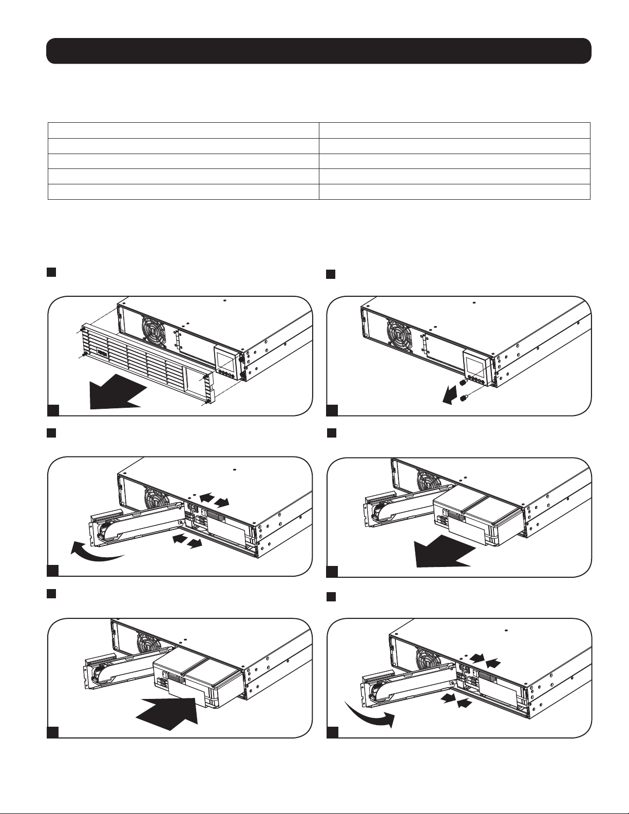
Internal Battery Replacement
Battery Replacement Door: Under normal conditions, the original battery in your UPS will last several years. Battery replacement
should be performed only by qualified service personnel. Refer to “Battery Warnings” in the Safety section. If you require a replacement
battery, you can find it at tripplite.com/support/battery/index.cfm. See the chart below to find the right replacement battery for your UPS
system:
UPS Model Replacement Battery Cartridge
SUINT1000LCD2U RBC24S
SUINT1500LCD2U RBC36S
SUINT2200LCD2U RBC48S
SUINT3000LCD2U / SU3000LCD2UHV RBC72S
See the following diagrams for battery removal and installation procedures.
All Models
Note: The SUINT1000LCD2U is shown, but the procedure is the same for the other units.
1
Remove the four front screws from the front bezel and take
it off.
2
Loosen the two screws securing the front plate.
1 2
3
Open the front plate. Disconnect battery power cable and
communication cable.
3
5
Install new battery pack into the UPS in the same position as
the original pack.
4
Remove old battery pack.
4
6
Reconnect battery power cable and communication cable.
Close the front plate.
5 6
25
Page 26
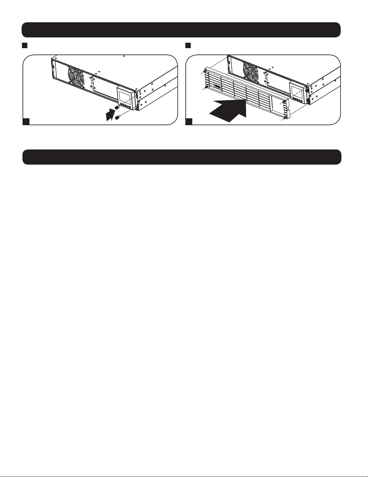
Internal Battery Replacement
7
Tighten the two screws to secure the front plate.
8
Replace the four front screws to secure the bezel.
7 8
Storage and Service
Storage
First turn your UPS OFF: press the “OFF” switch to turn power off at the UPS outlets, then disconnect the power cord from the wall
outlet. Next, disconnect all equipment to avoid battery drain. If you plan on storing your UPS for an extended period of time, fully
recharge the UPS batteries once every three months by plugging the UPS into a live AC outlet and letting the UPS charge for 4-6 hours.
If you leave your UPS batteries discharged for an extended period of time, they may suffer permanent loss of capacity.
Service
A variety of Extended Warranty and On-Site Service Programs are also available from Tripp Lite. For more information on service, visit
tripplite.com/support. Before returning your product for service, follow these steps:
1. Review the installation and operation procedures in this manual to ensure that the service problem does not originate from a
misreading of the instructions.
2. If the problem continues, do not contact or return the product to the dealer. Instead, visit tripplite.com/support.
3. If the problem requires service, visit tripplite.com/support and click the Product Returns link. From here you can request a Returned
Material Authorization (RMA) number, which is required for service. This simple on-line form will ask for your unit’s model and serial
numbers, along with other general purchaser information. The RMA number, along with shipping instructions will be emailed to you.
Any damages (direct, indirect, special or consequential) to the product incurred during shipment to Tripp Lite or an authorized Tripp Lite
service center is not covered under warranty. Products shipped to Tripp Lite or an authorized Tripp Lite service center must have
transportation charges prepaid. Mark the RMA number on the outside of the package. If the product is within its warranty period,
enclose a copy of your sales receipt. Return the product for service using an insured carrier to the address given to you when you
request the RMA.
26
Page 27

Product Registration and Regulatory Compliance
Visit tripplite.com/warranty today to register your new Tripp Lite product. You'll be automatically entered into a drawing for a chance to win a FREE Tripp Lite product!*
* No purchase necessary. Void where prohibited. Some restrictions apply. See website for details.
Regulatory Compliance Identification Numbers:
For the purpose of regulatory compliance certifications and identification, your Tripp Lite product has been assigned a unique series number. The series number can be found
on the product nameplate label, along with all required approval markings and information. When requesting compliance information for this product, always refer to the series
number. The series number should not be confused with the marketing name or model number of the product.
FCC Specifications for Models with FCC Class A Approval:
This device complies with part 15 of the FCC Rules. Operation is subject to the following two conditions: (1) This device may not cause harmful interference, and (2) this
device must accept any interference received, including interference that may cause undesired operation.
Note: This equipment has been tested and found to comply with the limits for a Class A digital device, pursuant to part 15 of the FCC Rules. These limits are designed to
provide reasonable protection against harmful interference when the equipment is operated in a commercial environment. This equipment generates, uses, and can radiate
radio frequency energy and, if not installed and used in accordance with the instruction manual, may cause harmful interference to radio communications. Operation of this
equipment in a residential area is likely to cause harmful interference in which case the user will be required to correct the interference at his own expense. The user must use
shielded cables and connectors with this equipment. Any changes or modifications to this equipment not expressly approved by Tripp Lite could void the user’s authority to
operate this equipment.
EMC Specifications for Models with EMC Category C2 Approval (Select Models):
WARNING: This is a category C2 UPS product. In a residential environment, this product may cause radio interference, in which case the user may be required to take
additional measures.
WEEE Compliance Information for Tripp Lite Customers and Recyclers (European Union)
Under the Waste Electrical and Electronic Equipment (WEEE) Directive and implementing regulations, when customers buy new electrical and electronic equipment
from Tripp Lite they are entitled to:
• Send old equipment for recycling on a one-for-one, like-for-like basis (this varies depending on the country)
• Send the new equipment back for recycling when this ultimately becomes waste
FCC Part 68 Notice (United States Only)
If your Modem/Fax Protection causes harm to the telephone network, the telephone company may temporarily discontinue your service. If possible, they will notify you in
advance. If advance notice isn’t practical, you will be notified as soon as possible. You will be advised of your right to file a complaint with the FCC. Your telephone company
may make changes in its facilities, equipment, operations or procedures that could affect the proper operation of your equipment. If it does, you will be given advance notice
to give you an opportunity to maintain uninterrupted service. If you experience trouble with this equipment’s Modem/Fax Protection, please visit tripplite.com/support for repair/
warranty information. The telephone company may ask you to disconnect this equipment from the network until the problem has been corrected or you are sure the equipment
is not malfunctioning. There are no repairs that can be made by the customer to the Modem/Fax Protection. This equipment may not be used on coin service provided by the
telephone company. Connection to party lines is subject to state tariffs. (Contact your state public utility commission or corporation commission for information.)
UPS and Battery Recycling
Please recycle Tripp Lite Products. The batteries used in Tripp Lite products are sealed Lead-Acid batteries. These batteries are highly recyclable.
Please refer to your local codes for disposal requirements.
You can call Tripp Lite for recycling info at +1.773.869.1234.
You can go the Tripp Lite Website for up-to-date information on recycling the batteries or any Tripp Lite product.
Please follow this link: tripplite.com/en/support/recycling-program.cfm
Tripp Lite has a policy of continuous improvement. Specifications are subject to change without notice. Photos and illustrations may differ slightly from actual products.
1111 W. 35th Street, Chicago, IL 60609 USA • www.tripplite.com/support
27
19-09-287 93-32CB_RevD
Page 28

Manual del Propietario
Sistemas UPS SmartOnline
Monofásicos en Línea para Instalación en Rack
con Pantalla LCD Integrada para Monitoreo y Control
No es adecuado para aplicaciones móviles.
®
SUINT1000LCD2U
(Número de Serie: AGPS8294)
1. Descripción General 29
Lista de Partes 29
Opciones de Accesorios Adicionales 29
Accesorios Específicos del Modelo 29
2. Instrucciones Importantes 29
de Seguridad
3. Diagrama de Bloques del 30
Circuito del UPS
4. Instalación 31
Instalación en Rack 31
Instalación en Torre 32
Conexión de las Comunicaciones 33
de la Batería Smart
5. Conexiones Básicas 34
y Arranque
Guía de Inicio Rápido 34
6. Características 36
Controles del Panel Frontal, 36
Grupo de LEDs y Pantalla LCD
Características del Panel Posterior 36
SUINT1500LCD2U
(Número de Serie: AGPS8295)
Guía de
Inicio Rápido—
Página 34
SUINT2200LCD2U
(Número de Serie: AGPS7958)
7. Operaciones 38
Pantalla de LCD y Controles del 38
Panel Frontal
Funciones de los Botones del 39
Panel Frontal
Distribución de la Pantalla de Inicio 39
Opciones de Selección de Estrategia 40
de Energía
Opciones de Selección y Configuración 42
del LCD del panel Frontal del UPS
Configuración de los Módulos de 45
Baterías Externas
8. Conexiones Opcionales 47
9. Solución de Problemas y 50
Registro de Eventos
10. Reemplazo de la Batería Interna 52
11. Almacenamiento y Servicio 53
12. Cumplimiento de las normas 54
English 1
Français 55
Русский 82
Deutsch 109
SUINT3000LCD2U
(Número de Serie: AGPS7959)
SU3000LCD2UHV
(Número de Serie: AGPS8296)
NOTA: Las opciones de módulos de baterías externas requieren configuración usando la interfaz de LCD del Panel frontal LCD o mediante el software de
1111 W. 35th Street, Chicago, IL 60609 USA • tripplite.com/support
Copyright © 2019 Tripp Lite. Todos los derechos reservados. SmartOnline® es una marca registrada de Tripp Lite.
CONFIGURACIÓN DE BATERÍA EXTERNA de Tripp Lite.
Para obtener las actualizaciones más recientes, visite tripplite.com
28
Page 29
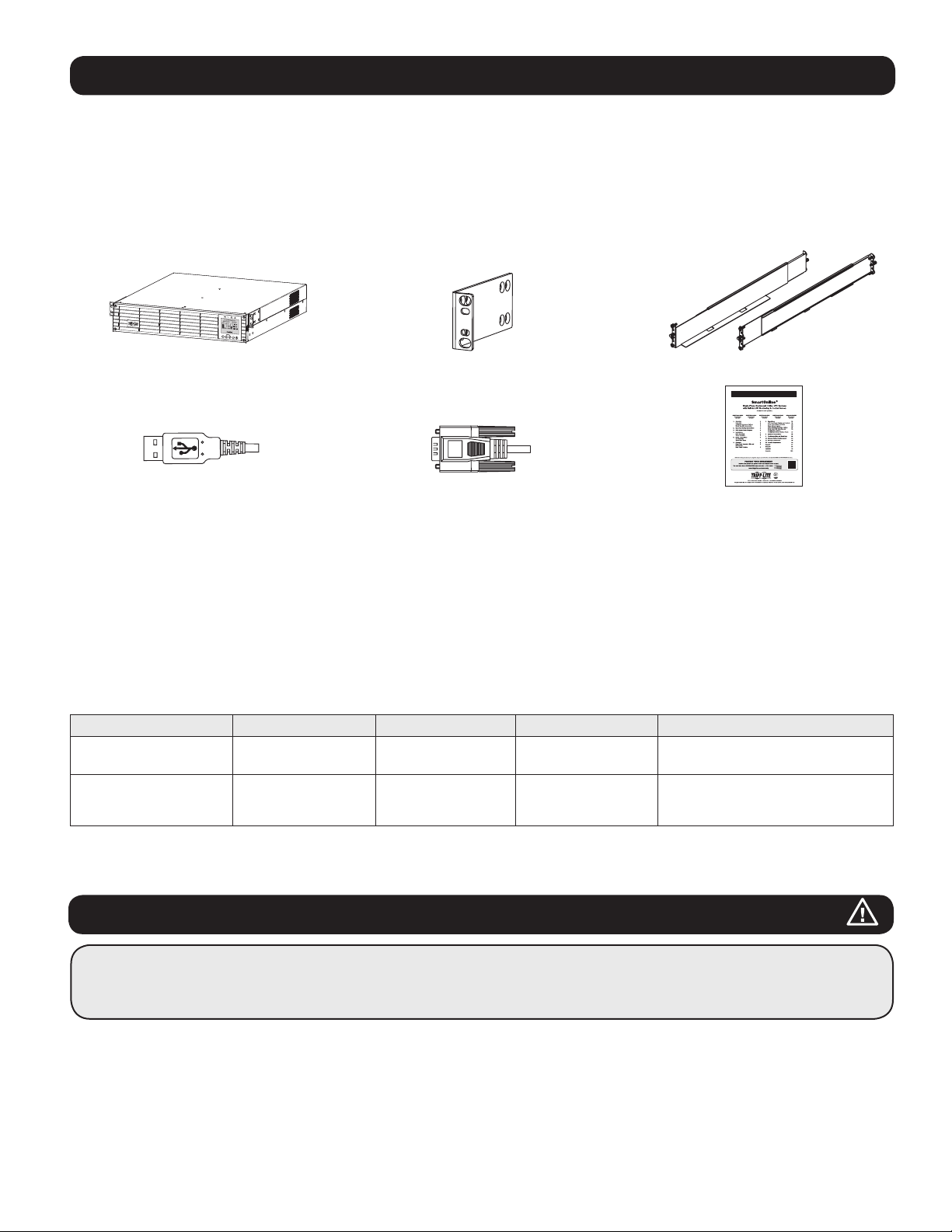
Descripción General
Sistemas UPS SmartOnline para Instalación en Rack de Tripp Lite; con interfaz de LCD interactiva cuenta con protección de UPS de
doble conversión, en línea, con salida permanente de onda sinusoidal y cero tiempo de transferencia adecuado para todas las
aplicaciones avanzadas de red. Cada sistema proporciona respaldo por batería de larga duración con autonomía extendida opcional y
capacidad de comunicaciones por Web. Las interfaces incorporadas incluyen USB, serial RS-232 y Apagado de Emergencia (EPO). La
pantalla LCD interactiva del panel frontal proporciona estado detallado del UPS, opciones de configuraciones predeterminadas y control.
La eficiencia máxima opcional y las opciones de estrategia de energía auto-adaptable permiten la operación con alta eficiencia con
consumo de energía y emisión de calor reducidos.
Lista de Partes
Sistema UPS Orejas de Instalación Atornillables (2) Juego de riel para 4 postes
Owner’s Manual
Owner’s Manual
Cable USB Cable RS-232 Manual del Propietario
Accesorios Adicionales (Todos los Modelos; Opcional)*
• SNMPWEBCARD: tarjeta de interna de interfaz de red para control y monitoreo por SNMP/Web
• WEBCARDLX: Tarjeta Para Administración Web
• 2POSTRMKITWM: Soporta UPS y módulos de baterías para instalación en rack en configuraciones para instalación en rack de 2
postes o instalación en pared
•
2-9USTAND: Soporta UPS y módulos de baterías en configuración de torre vertical
* Modelos selectos se embarcan también con cables adaptadores opcionales de Entrada/Salida.
Accesorios Específicos del Modelo (Opcionales)*
Modelo de UPS SUINT1000LCD2U SUINT1500LCD2U SUINT2200LCD2U SUINT3000LCD2U / SU3000LCD2UHV
Módulos de Baterías
Externas “SMART”**
Módulos de Baterías
Externas “NON-SMART”**
* Para información detallada de autonomía extendida y opciones de accesorios adicionales, visite la página de especificación para su Sistema UPS en tripplite.com.
** Para configuración de batería externa, consulte opciones y método de configuración en la sección de Operaciones. Los módulos de baterías SMART son detectados
automáticamente por el UPS.
BP24V36-2US BP36V27-2US BP48V27-2US BP72V18-2US
BP24V15RT2U (límite 1),
BP24V28-2U (límite 1),
BP24V70-3U
BP36V15-2U (límite 1)
BP36V42-3U
BP48V24-2U (límite 1)
BP48V60RT3U
BP72V15 (límite 1)
BP72V28RT3U
Instrucciones Importantes de Seguridad
CONSERVE ESTAS INSTRUCCIONES
Este manual contiene instrucciones y advertencias que deben seguirse durante la instalación, operación y almacenamiento de
todos los Sistemas UPS de Tripp Lite. La omisión en la observancia de estas advertencias puede afectar su garantía.
Advertencias para la Ubicación del UPS
• Instale su UPS en interiores, alejado de humedad o calor excesivos, contaminantes conductores, polvo o luz solar directa.
• Para mejor desempeño, mantenga la temperatura interior entre 0º C y 40º C.
• Deje espacio adecuado alrededor del UPS para una ventilación apropiada.
• No instale la unidad con su panel frontal o posterior viendo hacia abajo (en cualquier ángulo). El instalar de esta manera
inhibirá seriamente el enfriamiento interno de la unidad, causando eventualmente daño al producto no cubierto por la garantía.
29
Page 30
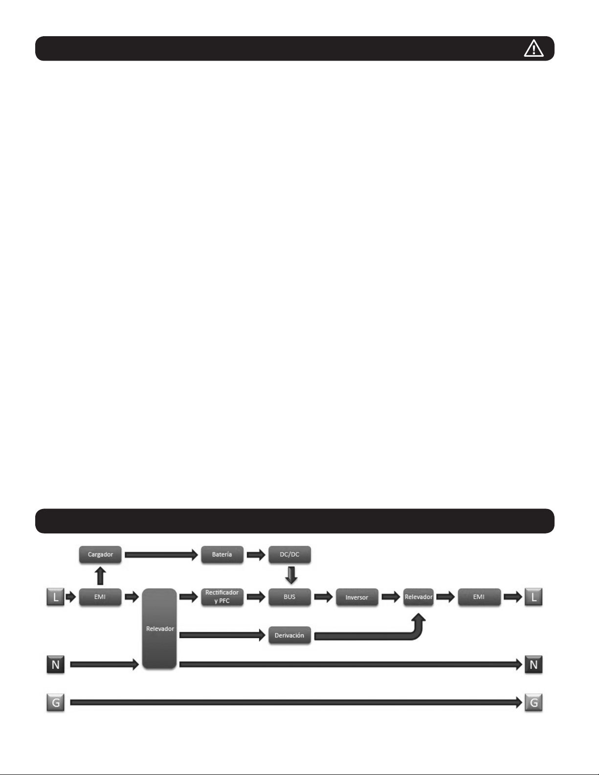
Instrucciones Importantes de Seguridad
Advertencias para la Conexión del UPS
• Conecte su UPS directamente a un tomacorriente de CA conectado correctamente a tierra. No enchufe el UPS en sí mismo; esto
dañará al UPS.
• No modifique la clavija del UPS y no use un adaptador que pueda eliminar la conexión a tierra del UPS.
• No use cables de extensión para conectar el UPS a un tomacorriente de CA. Si utiliza supresores de sobretensiones distintos a los
Tripp Lite para conectar su UPS a un tomacorriente, invalidará su garantía.
• Si el UPS recibe alimentación de un generador de CA activado por motor, debe probarse que el generador proporciona una salida de
grado computadora, limpia y filtrada.
• El tomacorriente que alimenta al UPS debe estar próximo al UPS y ser fácilmente accesible.
• Para eliminar el voltaje de CA del UPS, extraiga la clavija del tomacorrientes.
Advertencias para la Conexión del Equipo
• No se recomienda el uso de este equipo en aplicaciones de soporte de vida en donde la falla de este equipo pueda
consecuentemente causar la falla del equipo de soporte de vida o afectar significativamente su seguridad o efectividad.
• No conecte supresores de sobretensiones o cables de extensión a la salida de su UPS. Esto puede dañar al UPS y afectar las
garantías del supresor de sobretensiones y del UPS.
• Conecte el UPS a un tomacorriente que esté correctamente protegido contra corrientes excesivas, cortocircuitos, y fallas de conexión
a tierra como parte de la instalación del edificio. La protección del tomacorrientes para el UPS debe estar en serie con la alimentación
principal.
• Para reducir el riesgo de incendio, conecte solo a un circuito que tenga una protección contra sobre-corriente del circuito derivado con
una especificación de amperes de acuerdo con el National Electrical Code® (NEC®), ANSI/NFPA 70 o su código eléctrico local. En
Europa, el breaker debe cumplir la norma IEC/EN 60934 y tener una abertura de l contacto de al menos 3 mm. El breaker
recomendado para instalaciones en edificios es de 240V/20A.
Advertencias de la Batería
• Las baterías pueden presentar un riesgo de descarga eléctrica y quemaduras por la alta corriente de corto circuito. Observe las
precauciones apropiadas. No deseche las baterías en un fuego. No abra el UPS o las baterías. No ponga en corto o puentee las
terminales de la batería con objeto alguno. Desenchufe y apague el UPS antes de ejecutar el reemplazo de la batería. Use
herramientas con mangos aislados. No hay partes dentro del UPS a las que el usuario pueda dar servicio. El reemplazo de la batería
debe realizarlo sólo personal de servicio autorizado usando el mismo número y tipo de baterías (Plomo-Ácido Selladas). Las baterías
son reciclables. Para información sobre el reciclado, refiérase a sus códigos locales para los requisitos de desecho o visite
tripplite.com/UPSbatteryrecycling. Tripp Lite ofrece una línea completa de Cartuchos de Batería de Repuesto (R.B.C.) para Sistema
UPS. Visite Tripp Lite en el sitio tripplite.com/support/battery/index.cfm para determinar la batería de repuesto específica para su UPS.
Nota: Para la configuración de la batería externa, consulte opciones y método de configuración en la sección de Operaciones. Los MÓDULOS DE BATERÍAS SMART son
detectados automáticamente por el UPS.
Diagrama de Bloques del Circuito del UPS
30
Page 31

Instalación
Instalación en Rack
instale su equipo es un rack o gabinete de 4 postes o de 2 postes. Antes de la instalación, el usuario debe determinar la adecuación de
los accesorios y procedimientos. Si los accesorios y procedimientos no son adecuados para su aplicación, póngase en contacto con el
fabricante de su rack o gabinete. Los procedimientos descritos en este manual son para tipos comunes de racks y gabinetes y pueden
no ser apropiados para todas las aplicaciones.
Instalación en 4 Postes
1
Las espigas de plástico A incluidas soportarán temporalmente
los entrepaños B vacíos para instalación en rack mientras
usted instala los accesorios de instalación permanentes.
Inserte una espiga en el tercer orificio de la parte superior en
el frente de cada soporte. En el extremo posterior, inserte una
espiga en el orificio central. (Cada soporte frontal tiene 6
orificios y cada soporte trasero tiene 5 orificios). Las espigas
se abrocharán es su lugar.
Después de instalar las espigas, expanda cada entrepaño para
hacer coincidir la profundidad de los rieles de su rack. Las
espigas ajustarán a través de los orificios cuadrados en los
rieles del rack para soportar los entrepaños. Consulte las
etiquetas en la unidad de rack para confirmar que los
entrepaños estén nivelados en todas direcciones.
Nota: El borde de apoyo de cada entrepaño debe apuntar hacia adentro.
1
A
B
A
C
B
2
Retire las espigas en el extremo frontal de cada soporte.
Asegure permanentemente los entrepaños B a los rieles de
instalación usando los tornillos y las arandelas de copa
C
como se muestra. Coloque 2 tornillos en el frente de cada riel
(4 en toral) y 2 tornillos en la parte posterior de cada riel (4 en
total). Apriete todos los tornillos antes de continuar.
Nota: Las espigas posteriores pueden dejarse colocadas para instalación, pero
las delanteras deben retirarse antes de fijar con tornillos el soporte.
¡ADVERTENCIA!
No intente instalar su UPS hasta que haya insertado y
apretado los tornillos requeridos. Las espigas de
plástico no soportarán el peso de su UPS.
3 Coloque los soportes de instalación de su UPS D a los
orificios delanteros de instalación E del UPS usando los
accesorios incluidos F. Las “orejas” del soporte de instalación
deben apuntar al frente.
4
Con la ayuda de un asistente (si fuera necesario), levante su
UPS y deslícelo en los entrepaños. Coloque los soportes de
instalación del UPS en los rieles de instalación delanteros con
los tornillos y arandelas suministrados por el usuario
G
.
Apriete con firmeza todos los tornillos.
C
2
E
D
F
3
G
4
G
Instalación en 2 Postes
Si instala modelos de UPS de 2U en racks de 2 postes, éstos requieren la adición de un Juego de Instalación para Rack de 2 Postes
de Tripp Lite (modelo: 2POSTRMKITWM, vendido por separado). Para el procedimiento de instalación consulte el manual del propietario
del juego de instalación.
31
Page 32

Instalación
Instalación en Torre
Su UPS puede instalarse en una posición de torre vertical con los
soportes de base opcionales vendidos por separado por Tripp Lite
(modelo: 2-9USTAND). Al instalar el UPS sobre soportes de base
ajustables, asegúrese de que el panel de control quede hacia la
parte superior. El panel de control puede girarse para facilitar la
lectura. Retire los 4 tornillos delanteros del panel frontal y
extráigalo. Pique las lengüetas ubicadas en los costados del panel
LCD y gírelo. Reinstale el panel frontal y fíjelo. La configuración el
panel frontal debe ejecutarla personal de servicio solamente.
¡ADVERTENCIA!
Todos los sistemas UPS son extremadamente pesados. Tenga
cuidado el levantarlos e instalarlos. El usuario debe
estabilizar adecuadamente el UPS al levantarlo e instalarlo.
Modelo de UPS SUINT1000LCD2U SUINT1500LCD2U SUINT2200LCD2U SUINT3000LCD2U / SU3000LCD2UHV
Dimensiones del
UPS (Al x An x Pr)
Altitud de Operación: 0 a 3000 m
8.6 x 43.8 x 39.6 cm 8.6 x 43.8 x 49.6 cm 8.6 x 43.8 x 49.6 cm 8.6 x 43.8 x 61.6 cm
32
Page 33

2
1
Instalación
Conexión de las Comunicaciones de la Batería Smart
Su UPS soporta la detección automática de sus baterías internas y hasta 6 MÓDULOS DE BATERÍAS SMART externos. Antes de
alimentar el UPS de la energía de la red pública de CA, debe conectar el cable de comunicación interna de BATERÍA SMART de la
siguiente manera:
1
Retire los 4 tornillos delanteros del bisel frontal y retírelo.
1 2
2
Afloje los 2 tornillos que sujetan la placa frontal.
3
Abra la placa frontal.
3
5
Apriete los 2 tornillos para sujetar la placa frontal.
4
Conecte el cable de comunicación de la BATERÍA SMART.
Cierre la placa frontal.
4
6
Vuelva a colocar los 4 tornillos frontales para sujetar el bisel.
5 6
NOTA SOBRE LA CONFIGURACIÓN DE LA BATERÍA EXTERNA
Si se usarán módulos de baterías externas con este UPS, instálalos siguiendo la documentación para la instalación, incluida con cada
módulo de baterías. La instalación de módulos de baterías externas requiere que el UPS se configure en alguna de dos formas distintas:
1. Mediante la interfaz LCD del panel frontal del UPS
2. Mediante el software para CONFIGURACIÓN DE BATERÍAS EXTERNAS de Tripp Lite
Este UPS esté programado de fábrica con curvas de descarga y perfiles de carga para configuraciones de módulos de baterías externos
accesibles mediante la interfaz LCD del panel frontal del UPS. Las opciones de módulos de baterías externas adicionales que usan
módulos de baterías externas más grandes o múltiples también son soportadas, pero requieren de configuración usando el software para
CONFIGURACIÓN DE BATERÍAS EXTERNAS de Tripp Lite y una conexión de puerto serial al UPS.
33
Page 34

Conexiones Básicas y Arranque
Guía de Inicio Rápido - Encendido Inicial del UPS
1
Enchufe el cable de alimentación de su UPS en
un tomacorriente
Su UPS debe estar conectado a un circuito dedicado con
suficiente capacidad en amperes.
Para más detalles, refiérase a la tabla de clasificación
etiquetada en el UPS.
2
Seleccione su Idioma
Cuando se conecte su UPS por primera vez, se encenderá el
LED IMPUT AC y la pantalla LCD del panel frontal solicitará una
selección de idioma.
Usando los botones UP / DOWN
preferencia de idioma, después oprima el botón NEXT
, seleccione su
.
La interfaz confirmará su selección y proporcionará opciones
para regresar (oprima BACK
(oprima NEXT
).
ESC
) o adelantar al siguiente paso
Language
English
Back Next
SETUP
ESC
2
4
Seleccione su Contraseña
A continuación, el UPS le solicitará seleccionar la
CONTRASEÑA deseada.
Usando los botones UP / DOWN
dígito de su contraseña deseada y oprima el botón NEXT
para avanzar al segundo dígito. Repita para los dígitos 2 a 4.
Nota: Para configurar rápidamente la contraseña en “0 0 0 0” oprima cuatro
veces el botón NEXT.
, seleccione el primer
1
3
Seleccione su Estrategia de Energía
A continuación, el UPS le solicitará seleccionar la ESTRATEGIA
DE ENERGÍA deseada.
Usando los botones UP / DOWN
preferencia de ESTRATEGIA DE ENERGÍA y oprima el botón
APPLY
.
Para consultar las características de operación de cada
estrategia de energía, vea las secciones de Opciones de
Estrategia de Energía y Modos de Operación del UPS bajo
la sección de Operaciones.
Power Strategy
Auto-Adaptive
Max Efficiency
Max Quality
Freq. Regulation
Freq. Conv. To 60Hz
Freq. Conv. To 50Hz
Back Select Apply
SETUP
ESC
3
5
Seleccione el voltaje de salida del UPS
Después, el UPS le solicitará seleccionar el VOLTAJE DE
SALIDA deseado.
Usando los botones UP / DOWN
salida del UPS y oprima el botón APPLY
Output Voltage
, seleccione su
, seleccione el voltaje de
.
Password Setup
0 0 0 0
Back Select Next
SETUP
ESC
4
34
200 Vac
208 Vac
220 Vac
230 Vac
240 Vac
Back Select Apply
SETUP
ESC
5
Page 35

Conexiones Básicas y Arranque
6
Seleccione la Alerta de Envejecimiento de la Batería
del UPS
A continuación, el UPS le solicitará seleccionar la programación
de la ALERTA DE ENVEJECIMIENTO DE LA BATERÍA.
Usando los botones UP / DOWN
, seleccione el tiempo de
la alerta de envejecimiento de la batería en meses, después
oprima el botón APPLY
.
Batt Age Alert
Months:36
Back Select Apply
SETUP
ESC
6
7
Seleccione el estado ACTIVO / INACTIVO de la
alarma acústica
Después, el UPS le solicitará seleccionar el estado ACTIVO /
INACTIVO de la alarma.
Usando los botones UP / DOWN
, seleccione el estado
ACTIVO / INACTIVO de la alarma, después oprima el botón
APPLY
.
Nota: La inactivación de la alarma evita que la alarma acústica suene durante
fallas del suministro eléctrico y condiciones del falla del UPS solamente. La
alarma aún emitirá aún un “tono” para confirmar la orden del operador
mediante los botones de navegación del LCD del panel frontal cuando se
inactive la alama.
Audible Alarm
Enabled
Disabled
Back Select Apply
SETUP
ESC
7
8
Enchufe su equipo en el UPS.
Su UPS está diseñado para soportar solamente equipo de red,
servidor y cómputo.
Su modelo y tomacorriente pueden variar.
8
9
Encienda su UPS
Oprima y sostenga el botón “POWER” [Encendido]
por 3
segundos y suéltelo cuando la alarma empiece a sonar.
9
El UPS iniciará entonces una serie de comprobaciones de
diagnóstico antes de activar la energía de salida. Una vez que
el UPS reporta el estado de operación NORMAL / CARGA
PROTEGIDA con la ESTRATEGIA DE ENERGÍA activada, su UPS
puede ponerse inmediatamente en servicio para proporcionar
protección confiable contra una amplia variedad de problemas
de energía.
35
Page 36

Características
Antes de instalar y operar su UPS, familiarícese con las ubicaciones y función de las características de cada componente.
Controles del Panel Frontal, Grupo de LEDs y Pantalla LCD
El LCD gráfico en el panel frontal contiene una amplia gama de
condiciones de operación y datos de diagnóstico del UPS. Muestra
además las configuraciones y opciones del UPS cuando se visualizan
las pantallas de configuraciones del UPS. Los cinco botones debajo
del LCD pueden usarse para navegar en las diversas pantallas de
información, configuración y control del UPS siguiendo las
indicaciones y opciones de selección en la pantalla. Los indicadores
LED adicionales arriba de la pantalla LCD proporcionan también en
una ojeada el estado de la fuente de entrada de CA, disponibilidad
de salida, estado de la batería y estado de advertencia/falla.
Para descripciones detalladas de funciones del LCD, botones y LEDs,
consulte la sección de Operaciones.
Características del Panel Posterior
1
Conexión del Cable de Alimentación: Este conecta a la energía de CA mediante un cable con la clavija específica del país
suministrado por el usuario o un cable de alimentación.
2
Tomacorrientes de CA (varía por modelo): Estos tomacorrientes alimentan a su equipo conectado con una salida de CA de
onda sinusoidal pura durante la operación normal y energía de batería durante apagones y caídas de voltaje severas. La energía
provista por estos tomacorrientes está filtrada para proteger a los equipos conectados contra las dañinas sobretensiones y ruidos en
la línea Los tomacorrientes están divididos en bancos de carga numerados, como está etiquetado en la unidad. Mediante el uso del
Software PowerAlert y cableado, los bancos de carga uno y dos pueden apagarse y encenderse individualmente desde una ubicación
remota, permitiendo a los usuarios restaurar o reiniciar el equipo conectado.
3
Enchufes con Protección para Teléfono o Teléfono/Red: Estos enchufes protegen a su equipo contra sobretensiones sobre
una línea telefónica o línea de datos telefónica/red. La conexión de su equipo a estos conectores es opcional. Su UPS trabajará
correctamente sin esta conexión.
Nota: No es compatible con aplicaciones de PoE (Energía sobre la Ethernet).
4
Puertos de Comunicaciones (USB o RS-232): Estos puertos conectan su UPS a cualquier estación de trabajo o servidor. Use
con el Software PowerAlert de Tripp Lite y los cables incluidos para habilitar su computadora para guardar automáticamente los
archivos abiertos y apague el equipo durante un apagón. Use también el Software PowerAlert para monitorear una amplia variedad
de condiciones de la alimentación de CA y operación del UPS. Para más información, consulte su manual del Software PowerAlert o
póngase en contacto con Soporte al Cliente de Tripp Lite. El puerto RS-232 de 9 terminales permite además comunicaciones de
contacto seco. Consulte Comunicaciones USB y Serial RS-232 en la sección Conexiones Opcionales para las instrucciones de
instalación.
5
Puerto EPO, (Emergency Power Off), [Apagado de Emergencia]: Su UPS cuenta con un puerto EPO que puede usarse para
conectar el UPS a un interruptor de cierre de contacto para activar el apagado de emergencia del inversor. Para detalles, consulte la
sección Conexiones Opcionales.
6
Ranura Auxiliar: Retire el panel pequeño de la cubierta de esta ranura para usar accesorios opcionales para monitorear y controlar
su UPS en forma remota. Visite tripplite.com para ver una lista completa de accesorios, incluyendo la WEBCARDLX para monitoreo y
control remoto del UPS, así como una amplia variedad de productos para administración de redes y conectividad.
7
Conector del Módulo de Baterías Externas (la configuración varía según el modelo): Su UPS soporta el uso de módulos
opcionales de baterías externas de Tripp Lite para una autonomía adicional. Para instrucciones de configuración, vea la sección
Accesorios por Modelo Específico bajo la sección de Descripción General para consultar modelos compatibles y limitaciones y la
sección de Configuración de Módulos de Baterías Externas bajo la sección Operaciones.
Nota: Las opciones de módulos de baterías externas requieren configuración usando la interfaz de LCD del Panel frontal LCD o mediante el software de CONFIGURACIÓN
DE BATERÍA EXTERNA de Tripp Lite.
8
Tornillo de Conexión a Tierra: Úselo para conectar cualquier equipo que requiera una conexión de tierra a chasís.
9
Puerto de Detección de Batería Externa: Para baterías externas con comunicación incorporada, al conectar el cable de
comunicación de la batería en este puerto permitirá al UPS detectar automáticamente la batería externa.
36
Page 37

Características
SUINT1000LCD2U
8
SUINT1500LCD2U
8
SUINT2200LCD2U
2 9
1
1
1
2
2
2
2
9
9
7
7
3
4
5 6
3
4
5
6
3
8
SUINT3000LCD2U
8
SU3000LCD2UHV
2
2
2
1 5
2
2 3
7
9
7
9
3
4
5
6
4
6
4
8
6
2
1
37
57
Page 38

Operaciones
Esta sección explica cómo usar su Sistema UPS en Línea de Tripp Lite, incluyendo la operación del LCD en el panel frontal, modos de
operación, arranque y paro del UPS, transferencia entre modos, configuración de estrategia de energía y configuración de parámetros de
derivación, segmentos de carga y parámetros de la batería.
Pantalla de LCD y Controles del Panel Frontal
En el frente del UPS hay una pantalla LCD gráfica de 5 botones con indicadores LED adicionales que proporciona información sobre el
estado del UPS, información del nivel de carga, información de eventos, mediciones, parámetros y una amplia variedad de opciones de
configuración del UPS y de estrategia de energía.
LED de Salida de CA (Verde) LED de Modo de Batería (Amarillo)
LED de Entrada de CA (Verde)
Pantalla LCD
LED de Falla (Rojo)
Escape
Página Arriba/Página Abajo
Encendido/Apagado
Ingresar
Indicadores LED del Panel Frontal
Hay 4 LEDs arriba de la pantalla LCD del panel frontal que ofrecen información sobre estado de ALIMENTACIÓN DE CA, DERIVACIÓN,
SALIDA DE CA, MODO DE BATERÍA y FALLA DE UPS.
Indicador de ALIMENTACIÓN DE CA
Encendido La entrada de CA está disponible Y la entrada de CA está DENTRO del rango del modo ECONÓMICO /
DERIVACIÓN. Cuando este LED está ENCENDIDO PERMANENTE, la entrada de CA es de calidad adecuada
para la operación el UPS en MODO ECONÓMICO o DERIVACIÓN.
Destellando La entrada de CA está disponible Y la entrada de CA está FUERA del rango del modo DERIVACIÓN.
Cuando este LED está ENCENDIDO DESTELLANDO, la entrada de CA no es de voltaje o frecuencia adecuados
para la operación el UPS en MODO ECONÓMICO o DERIVACIÓN.
Apagado La entrada de CA NO está disponible.
Cuando este LED está apagado, la entrada de CA NO está disponible.
Indicador de SALIDA DE CA
Encendido La salida de CA del UPS está activa
Está disponible la salida del UPS en los tomacorrientes de salida del UPS.
Apagado La salida de CA del UPS está inactiva
La salida de CA del UPS no está disponible.
Indicador de MODO DE BATERÍA
Encendido El UPS está funcionando en modo de batería Las baterías del UPS se están descargando y el UPS funciona
en modo de batería. Además se enciende momentáneamente durante la operación del autodiagnóstico.
Destellando El UPS está funcionando en modo de batería - Advertencia de batería baja Las baterías del UPS se
están descargando y el UPS funciona en modo de BATERÍA y están llegando a nivel bajo. El indicador destellará
en intervalos de 2 segundos para informar BATERÍA BAJA y en intervalos de 0.5 segundos para indicar que las
BATERÍAS ESTÁN CASI TOTALMENTE DESCARGADAS y el UPS está próximo a apagarse.
Indicador de FALLA DEL UPS
Encendido El UPS está experimentando un estado de falla predeterminada
Para explicación del estado o información del código del error, vea la pantalla del panel frontal. Para
orientación sobre solución de problemas, vea las instrucciones en la pantalla y el manual.
Apagado Normal
El UPS no está reportando condiciones de falla cuando este indicador está apagado.
38
Page 39

Operaciones
Funciones de los Botones del Panel Frontal
Hay 5 botones en el panel frontal que ofrecen opciones de control y configuración del UPS. Use los 5 botones de interfaz del panel
frontal y siga las indicaciones y opciones de selección en pantalla para navegar en las diversas pantallas de información, configuración y
control del UPS.
Botón de Encendido / Apagado: Este control ofrece tres funciones principales: Encendido, Apagado y Borrado de Falla del
UPS.
Para encender el UPS en un modo de operación protegido, oprima y sostenga este botón durante 3 segundos cuando el
UPS esté conectado a una alimentación de CA. Suelte el botón cuando la alarma empiece a sonar y el UPS arrancará en la
última estrategia de energía configurada.
Para “Arranque en Frío” del UPS en modo de batería durante condiciones de falla del suministro eléctrico, oprima y
sostenga este botón durante 3 segundos. Suelte el botón cuando la alarma empiece a sonar y el UPS arrancará en modo de
batería.
Para apagar el UPS mientras esté funcionando en modo de batería o protegido, optima y sostenga este botón durante 3
segundos. Suelte el botón cuando la alarma empiece a sonar. El UPS apagará la salida de CA. Una vez que la salida de CA
esté apagada, desconecte la energía de alimentación al UPS y éste se desenergizará completamente.
Para BORRAR LA FALLA DEL UPS, oprima y sostenga este botón durante 3 segundos como se indicó en pantalla. El UPS
borrará las condiciones de falla y regresará al modo en espera o en derivación.
Botón ENTER: Este control se usa para hacer selecciones, confirmar opciones y desplazarse a la siguiente selección cuando
el UPS es configurado en el modo de configuración. Oprima este botón como se indica en pantalla en modo de Configuración
para Ingresar, Confirmar o Desplazarse en el proceso de configuración.
Botones ARRIBA / ABAJO: Estos controles ofrecen dos funciones principales: Control direccional “Arriba” y “Abajo”, además
ingresar / salir del modo de configuración (al oprimirlos simultáneamente). Estos botones se usan para navegar las opciones
del menú de modo de configuración y cambiar arriba o abajo para ver los contenidos de la pantalla como se necesite.
Para INGRESAR o SALIR del MODO DE CONFIGURACIÓN DEL UPS, oprima estos dos botones simultáneamente durante 3
segundos. Suelte el botón cuando la alarma empiece a sonar. El UPS ingresará automáticamente al modo de configuración si
son oprimidos ambos botones durante los modos de la pantalla LCD. El UPS saldrá automáticamente del modo de
configuración si son oprimidos ambos botones mientras el UPS funciona en modo de configuración.
Botón ESCAPE: este control ofrece tres funciones principales: Cancelación de Alarma, Borrar Falla y operaciones de Regresar
/ Cancelar.
Para CANCELAR ALARMA DEL UPS, oprima este botón. Si ocurre una nueva condición de alarma, la alarma sonará
nuevamente.
Para CANCELAR o REGRESAR UN NIVEL, oprima este botón como se indica en pantalla en los modos de Navegación y
Configuración.
Distribución de la Pantalla de Inicio
La pantalla LCD del panel frontal del UPS está configurada para proporcionar información continua de operación del UPS usando
pantallas de inicio de MODO NORMAL y MODO DE BATERÍA que reportan continuamente el modo de operación, estado de protección,
estrategia de energía y un número de parámetros de operación de batería y nivel de carga.
Pantalla de Inicio de Modo Normal
Modo de Operación Estado de
Carga de la
Batería %
Carga de la
Batería “Barras”
Voltaje de la Batería
Estrategia de
Energía
<Battery> <Load>
ESC
Online
0.5 KW
0.5 KVA26.1VDC
Max Efficiency
SETUP
39
Load Protected
<Battery> <Load>
0.5 KW
0.5 KVA26.1VDC
Enabled
SETUP
ESC
Protección
Carga de Salida %
Carga de Salida
(Kilowatts)
Carga de Salida
(KVA)
Carga de Salida
“Barras”
Estrategia de
Energía
(Continuación)
Page 40

Operaciones
Opciones de Selección de Estrategia de Energía
Los sistemas UPS con LCD SmartOnline de Tripp Lite ofrecen diferentes opciones incorporadas de estrategias de energía que permiten al
UPS optimizar el rendimiento para cumplir con las necesidades del usuario para una operación con MÁXIMA CALIDAD DE ENERGÍA,
MÁXIMA EFICIENCIA y REGULACIÓN DE FRECUENCIA O CONVERSIÓN DE FRECUENCIA. Una estrategia adicional AUTO-ADAPTABLE
combina los beneficios de alta eficiencia y máxima calidad de energía. Cada opción de Estrategia de Energía permite que el UPS cambie
automáticamente entre modos de operación específicos según dicte el estado de la energía y del UPS. Las opciones disponibles de
estrategia de energía incluyen:
• Estrategia de Energía Auto-Adaptable capacita al UPS para cambiar automáticamente entre MODO EN LÍNEA y MODO ECONÓMICO
según indique la calidad y confiabilidad de la energía de alimentación del UPS. Si el UPS no sufre una falla del suministro eléctrico en
una semana (sin incluir autodiagnóstico del UPS) el UPS conmutará automáticamente al MODO ECONÓMICO. Si ocurre una falla del
suministro eléctrico, el UPS mantendrá la salida en MODO DE BATERÍA. Cuando se restaura la energía, el UPS repetirá el ciclo
operando en MODO EN LÍNEA hasta que no haya fallas de energía durante una semana.
• Estrategia de Energía de Máxima Eficiencia habilita al UPS para operar en forma continua en MODO ECONÓMICO siempre que la
alimentación de CA esté dentro del rango de voltaje alto/bajo configurado para derivación. Si el voltaje de entrada del UPS está fuera
del rango de derivación configurado, el UPS cambiará automáticamente al MODO EN LÍNEA hasta que el voltaje de entrada de CA se
restablezca dentro del rango de voltaje de derivación configurado. Esta es similar a la Estrategia de Energía Auto-Adaptable, excepto
que la transferencia al MODO ECONÓMICO es inmediata al recuperarse el nivel de voltaje. No se requiere el período de una semana
de operación libre de falla del suministro eléctrico para que el UPS retorne a operación en MODO ECONÓMICO.
• Estrategia de Energía de Máxima Calidad habilita al UPS para funcionar continuamente en MODO EN LÍNEA todo el tiempo que la
energía entrante de CA esté dentro del rango para la operación en modo en línea. El UPS permanecerá operando en forma continua
en modo En Línea de Doble-Conversión, suministrando energía de salida de la mayor calidad con cero tiempo de transferencia. El
modo de derivación automática está disponible durante los modos de falla del UPS cuando la entrada de CA está dentro del rango de
derivación.
• Estrategia de Energía con Regulación de Frecuencia es similar a la Estrategia de Energía de Máxima Calidad, excepto que el UPS
regulará en forma activa la frecuencia de salida dentro de +/-0.05Hz de la frecuencia nominal de 50 o 60Hz medida en el arranque.
El UPS permanecerá operando en forma continua en modo En Línea de Doble-Conversión, suministrando energía de salida de la
mayor calidad con cero tiempo de transferencia. El modo de derivación automática está disponible durante los modos de falla del UPS
cuando la entrada de CA está dentro del rango de derivación.
• Estrategias de Energía con Conversión de Frecuencia a 60Hz y Conversión de Frecuencia a 50Hz son similares a la Estrategia
de Energía de Máxima Calidad, excepto que el UPS regulará en forma activa la salida dentro de +/-0.05Hz de los 50Hz (Configuración
de Conversión de Frecuencia a 50Hz) o 60Hz (Configuración de Conversión de Frecuencia a 60Hz). La derivación automática no está
disponible en el modo de CONVERSIÓN DE FRECUENCIA. Las aplicaciones típicas incluyen la conversión de 50 a 60Hz (o 60 a 50Hz)
para dispositivos electrónicos delicados.
Nota: La potencia máxima soportada en los modos de Regulación/Conversión de Frecuencia está reducida en un 30%.
Modos de Operación del UPS
Los sistemas UPS SmartOnline de Tripp Lite son capaces de conmutar automáticamente entre modos de operación bajo condiciones
especificadas en la Estrategia de Energía configurada. El UPS indica en forma continua el estado usando los LEDs y la pantalla LCD de
visualización interactiva del panel frontal.
• Modo en Respaldo por Batería es la respuesta automática del sistema UPS a fallas del suministro eléctrico y variaciones de voltaje
fuera del rango de voltaje en línea. En MODO DE RESPALDO POR BATERÍA, el UPS mantiene energía de salida de CA de onda
sinusoidal desde las reservas de la batería. Una vez restablecida la energía, el UPS regresará al modo de operación protegida como lo
determina la Estrategia de Energía configurada y la condiciones de la energía entrante.
• Modo En Línea (también conocido como MODO EN LÍNEA DE DOBLE CONVERSIÓN) ofrece en más alto nivel de protección al equipo.
En el MODO EN LÍNEA, el UPS regenera en forma activa energía de CA a CD, después de CD a CA para suministrar una salida de CA
regulada continuamente dentro del 2% del voltaje de salida nominal seleccionado con cero tiempo de transferencia conforme el UPS
conmuta entre los modos de EN LÍNEA y EN RESPALDO POR BATERÍA.
• Modo Económico ofrece operación ahorradora de energía con el más alto nivel de eficiencia de operación del UPS. En MODO
ECONÓMICO, el UPS ahorra energía desactivando el proceso en línea de doble conversión siempre que la energía de entrada esté
dentro del rango de voltaje del MODO ECONÓMICO. Si el voltaje de alimentación cae fuera del MODO ECONÓMICO, el UPS responderá
cambiando automáticamente al MODO EN LÍNEA hasta que se restablezca el voltaje de alimentación.
• Modo de Regulación de Frecuencia proporciona al UPS la capacidad de corregir variaciones de frecuencia presentes en la
alimentación del UPS. Para detalles, consulte la sección de Opciones de Selección de Estrategia de Energía.
• Los Modos de Conversión de Frecuencia a 60Hz y Conversión de Frecuencia a 50Hz da al UPS la capacidad de convertir
frecuencia de 50Hz a 60Hz (o 60Hz a 50Hz). Para detalles, consulte la sección de Opciones de Selección de Estrategia de Energía.
Nota: La potencia máxima soportada en los modos de Regulación/Conversión de Frecuencia está reducida en un 30%.
• Modo en Derivación ofrece energía filtrada y no regulada al equipo conectado.
40
Page 41

Operaciones
Características de Operación de la Estrategia de Energía y Modos de Operación del UPS Soportados
La Estrategia de Energía del UPS configurada proporciona un marco para la operación del UPS conforme cambia entre los modos de
operación según lo determinado por los eventos de energía y el estado del UPS. Cada Estrategia de Energía ofrece un grupo único de
parámetros de operación a los que el UPS se adhiere a fin de cumplir con las preferencias del usuario para alto rendimiento o alta
eficiencia. Están disponibles además opciones adicionales de regulación y conversión de frecuencia para aplicaciones avanzadas. La
tabla siguiente lista los modos de operación del UPS soportados por cada opción de Estrategia de Energía.
MODOS DE OPERACIÓN DEL UPS
El UPS cambia automáticamente entre los modos de operación como lo determine la Estrategia de
Energía configurada, energía actual y condiciones de estado del UPS.
Soporte para
MODO EN LÍNEA
AUTO ADAPTABLE
El UPS funciona
continuamente en MODO
ECONÓMICO después de
funcionar en MODO EN
LÍNEA por una semana
completa sin una falla del
suministro eléctrico.
MÁXIMA CALIDAD
El UPS funciona
continuamente en MODO
EN LÍNEA para mantener
la más alta calidad de
energía de salida para el
equipo conectado.
MÁXIMA EFICIENCIA
El UPS funciona en
MODO ECONÓMICO
todo el tiempo cuando la
alimentación está dentro
del rango de derivación.
REGULACIÓN DE
FRECUENCIA
El UPS regula la salida a
estar entre +/-0.05Hz de
la nominal.
CONVERSIÓN DE
FRECUENCIA a 60Hz
El UPS convierte la
alimentación de 50Hz a
60Hz. (+/-0.05Hz)
CONVERSIÓN DE
FRECUENCIA a 50Hz
El UPS convierte la
alimentación de 60Hz a
50Hz. (+/-0.05Hz)
OPCIONES DE SELECCIÓN DE ESTRATEGIA DE ENERGÍA
Su selección de Estrategia de Energía capacita al UPS para conmutar entre los modos de operación
como se describió
* El LCD muestra la REGULACIÓN DE FRECUENCIA como el modo de operación con información de la reducción de los valores establecidos.
** El LCD muestra la REGULACIÓN DE FRECUENCIA como el modo de operación con información de la reducción de los valores establecidos.
SI. Cuando la entrada
está dentro del rango de
voltaje EN LÍNEA, pero
fuera del rango de voltaje
de DERIVACIÓN y después
se restablece la energía
de CA.
SI. Cuando la
alimentación está dentro
del rango de voltaje EN
LÍNEA.
SI. Cuando la entrada
está dentro del rango de
voltaje EN LÍNEA, pero
fuera del rango de voltaje
de DERIVACIÓN.
SI. Cuando la
alimentación está dentro
del rango de voltaje EN
LÍNEA.*
SI. Cuando la
alimentación está dentro
del rango de voltaje EN
LÍNEA.**
SI. Cuando la
alimentación está dentro
del rango de voltaje EN
LÍNEA.**
Soporte para
MODO ECONÓMICO
SI. Cuando la entrada
está dentro del rango
de voltaje para MODO
ECONÓMICO y no hay
fallas del suministro
eléctrico por una semana.
NO. SI. SI. En caso de una falla
SI. Cuando la entrada
está dentro del rango
de voltaje del MODO
ECONÓMICO.
NO. SI. SI. En caso de una falla
NO. SI. NO.
NO. SI. NO.
Soporte para
MODO DE RESPALDO
POR BATERÍA
SI. SI. En caso de una falla
SI. SI. En caso de una falla
Soporte para
DERIVACIÓN
AUTOMÁTICA
del inversor del UPS
mientras el voltaje de
entrada está dentro
el rango de voltaje de
DERIVACIÓN.
del inversor del UPS
mientras el voltaje de
entrada está dentro
el rango de voltaje de
DERIVACIÓN.
del inversor del UPS
mientras el voltaje de
entrada está dentro
el rango de voltaje de
DERIVACIÓN.
del inversor del UPS
mientras el voltaje de
entrada está dentro
el rango de voltaje de
DERIVACIÓN.
41
Page 42

Operaciones
Opciones de Selección y Configuración del LCD del Panel Frontal del UPS
MENÚ PRINCIPAL / SUB-MENÚ OPCIONES DE PANTALLA / CONFIGURACIÓN DESCRIPCIÓN DE PANTALLA / CONFIGURACIÓN
ESTADO
Estado de Carga • Nivel de carga (%, kW, kVA, A, PF)
• Capacidad disponible (%, kW, kVA)
Estado de Entrada/Salida • Voltaje y frecuencia de entrada (VCA, Hz)
• Voltaje y frecuencia de salida (VCA, Hz)
• Grupo de Carga1 (Encendido/Apagado)
Estado de Energía • Eficiencia (%)
Estado de la Batería Interna • Instalado (mm/dd/aaaa)
Estado de Módulo de Baterías Externas • Modelo y número de serie del módulo
Tabla de Flujo de Energía • Consulte la tabla de flujo de operación
• Grupo de Carga2 (Encendido/Apagado)
• Potencia Promedio (kw/hr.)
• Estrategia de Energía configurada
• Expira (mm/dd/aaaa)
de baterías
• Instalado (mm/dd/aaaa)
• Expira (mm/dd/aaaa)
del UPS
CONTROL
Iniciar Prueba de la Batería • Inicia una prueba manual de la batería Inicia un autodiagnóstico momentáneo de la batería del UPS con
Restablecer la Antigüedad de la Batería • Restablece la antigüedad de la batería Restaura la antigüedad de la batería a la fecha actual. Use esta
Restauración de Estado de Falla • Restaura cualquier mensaje de estado
Auto-diagnóstico de Batería • Establece el intervalo regular de
de falla
autodiagnóstico de la batería
o Desactivado
o 4 semanas (configuración de fábrica)
o 13 semanas
o 26 semanas
REGISTRO DE EVENTOS
Eventos en Respaldo por Batería • Contador de eventos (Solo eventos del UPS
Todos los Eventos • Contador de eventos (todos los eventos)
Reiniciar los Eventos de Respaldo por
Batería
Reiniciar Todos los Eventos • Reinicia todos los eventos Reinicia todos los datos en el juego de pantalla de todos los
respaldado por batería)
• Minutos totales (total de minutos de
operación en modo de respaldo por batería)
• Falla más reciente del suministro eléctrico
(fecha)
• Días hasta alerta de remplazo de la batería
(días)
• Detalles del evento (fecha, hora y descripción
para los últimos 20 eventos registrados)
• Evento más reciente (fecha)
• Registro de hora de la fecha
• Detalles de evento (fecha, hora y descripción
para cada evento registrado)
• Reiniciar solamente los eventos de respaldo
por batería
PARÁMETROS
Configuración básica
Sistema
• Fecha actual (Mostrar, establecer fecha)
• Hora actual (Mostrar, establecer fecha)
• Alarma acústica (activar, desactivar)
• Idioma (seleccionar)
Voltaje de salida
• 200
• 208
• 220
• 230
• 240
Porcentaje de carga del UPS (%), kilowatt (kW), kilovoltampere
(kVA), amperes (A) y factor de potencia (PF).
Capacidad del UPS disponible en porcentaje (%), kilowatts (kW) y
kilovoltamperes (kVA).
Muestra información del estado de entrada y salida del UPS para
voltaje de entrada / salida (VCA), frecuencia (Hz) e información del
estado de energía del grupo de salida (Encendido/Apagado).
Muestra el porcentaje de eficiencia del UPS (%), consumo del
equipo conectado en kilowatt hora (kw/hr) y Estrategia de Energía
configurada.
Muestra la fecha de instalación del Cartucho de Batería Interna de
Repuesto y la fecha de expiración configurada por el usuario.
Muestra el número de modelo y número de serie del módulo de
baterías externas (MÓDULOS DE BATERÍAS SMART de Tripp Lite)
solamente, la fecha de instalación y la fecha de expiración
configurada por el usuario.
Muestra el modo de operación del UPS en una gráfica de flujo.
resultados inmediatos de aprobación/falla
función después del remplazo de una batería que NON-SMART.
Use esta función para borrar los mensajes de falla del UPS.
Use esta opción para iniciar la prueba automática de la batería a
intervalos regulares.
Muestra un resumen de todos los eventos de RESPALDO POR
BATERÍA cuando el UPS conmutó al modo de respaldo por batería
en respuesta a una condición protegida. Los detalles de eventos
listan los últimos 20 eventos de respaldo por batería. Según
ocurren alertas adicionales, los registros más antiguos serán
eliminados automáticamente.
Muestra un resumen de todos los eventos registrados. Los detalles
de eventos listan los últimos 20 eventos. Según ocurren alertas
adicionales, los registros más antiguos serán eliminados
automáticamente.
Reinicia todos los datos en el juego de pantalla de eventos de
respaldo por batería.
eventos.
Muestra, establece y restaura configuraciones de fecha, hora,
estado de la alarma acústica e idioma.
Nota: La configuración de DESACTIVAR la Alarma Acústica evita solo
alarmas por falla de energía y operativas, el UPS siempre sonará
para confirmar que está aceptando instrucciones del usuario desde
los botones de navegación del LCD del panel frontal.
Use la opción de CONFIGURACIONES / BÁSICA / VOLTAJE DE SALIDA
para mostrar o establecer el voltaje de salida nominal del UPS (los
cambios se efectuarán en el siguiente reinicio).
42
Page 43

Operaciones
MENÚ PRINCIPAL / SUB-MENÚ OPCIONES DE PANTALLA / CONFIGURACIÓN DESCRIPCIÓN DE PANTALLA / CONFIGURACIÓN
PARÁMETROS
Configuración básica
(continuación)
Configuración avanzada
Estrategia de Energía:
• Auto-Adaptable
• Máxima Eficiencia
• Máxima Calidad
• Regulación de Frecuencia
• Conversión de Frecuencia a 60Hz
• Conversión de Frecuencia a 50Hz
Batería:
• Configuración de la batería externa
o Configure mediante UPS
o Configurada con la PC
o Reemplazo de la Batería
• Alerta del Envejecimiento de la Batería
Sistema:
• Brillo de la pantalla
o Alto
o Medio (configuración de fábrica)
o Bajo
• Atenuación de la retro-iluminación: Ingrese
de 10 a 120 segundos (la configuración de
fábrica es de 60 segundos)
• Contraseña: Establezca su contraseña de 4
dígitos (la configuración de fábrica es 0000)
• Restaurar configuración de fábrica (restaura
todas las preferencias del UPS a los
parámetros de fábrica, incluyendo las
configuraciones de la batería)
Entrada/Salida:
• Nivel de Alerta por Sobrecarga: Ingrese un
valor entre el 5% y el 105% (la configuración
de fábrica es 100%)
• Configuración de la Acción en Caso de Falla
(respuesta del UPS a la falla)
o Ir a derivación (configuración de fábrica)
o Ir a en espera
• Límite Inferior de la Derivación: Ingrese un
valor del -5% al -20% (la configuración de
fábrica es -15%)
• Límite Superior de la Derivación: Ingrese un
valor del +5% al +20% (la configuración de
fábrica es +10%)
Encendido/Apagado:
• Arranque en Frío
o Activado (configuración de fábrica)
o Desactivado
• Reinicio Automático
o Activado (configuración de fábrica)
o Desactivado
• Retardo del Reinicio Automático
o Ingresar: de 0 a 60 segundos (la
configuración de fábrica es 5 segundos)
• Ahorro de Energía
o Ingresar: 0-100%
o Desactivado (configuración de fábrica)
• Modo de Apagado
o En Espera
o Derivación (configuración de fábrica)
• Batería Mínima para Reiniciar
o Ingrese: 10-90%
o Desactivado (configuración de fábrica)
43
Use la opción de CONFIGURACIONES / BÁSICA / ESTRATEGIA DE
ENERGÍA para mostrar o establecer la Estrategia de Energía del
UPS.
Ver la sección Opciones de Selección de Estrategia de Energía
bajo la sección de Operaciones para más información acerca de
las opciones disponibles de Estrategia de Energía.
Use la opción de CONFIGURACIONES / BÁSICA / BATERÍA para
configurar el UPS con módulos de baterías externas. Puede usarse
la opción de remplazo de batería para actualizar la fecha de
instalación para remplazo de batería externa Non-Smart del mismo
tipo. Además establece la duración de la alerta del envejecimiento
de la batería como recordatorio de remplazo de la misma.
Ver la sección Configuración de Módulos de Baterías Externas
bajo la sección de Operaciones para información de cómo
configurar módulos de baterías externas.
Use la opción de CONFIGURACIONES / AVANZADA / SISTEMA para
establecer las opciones del brillo de la pantalla, el tiempo de
atenuación de la retro-iluminación, la contraseña o restaurar la
configuración de fábrica.
Use CONFIGURACIONES / AVANZADA / ENTRADA-SALIDA para estas
opciones: Establece el porcentaje de carga de salida del UPS antes
de que se envíe una alerta de sobrecarga.
Establece la respuesta del UPS ante condiciones de falla que
requieran que el UPS salga del modo de doble conversión. La
opción de IR A DERIVACIÓN mantiene la salida de CA (mientras el
voltaje de entrada esté dentro de los límites alto/bajo de derivación).
La opción de IR A EN ESPERA causa que el UPS apague la salida
de CA en respuesta a condiciones de falla.
Especifica el voltaje de alimentación más bajo aceptable para
operación en derivación.
Especifica el voltaje de alimentación más alto aceptable para
operación en derivación.
Para estas opciones use CONFIGURACIONES / AVANZADA /
ENCENDIDO-APAGADO:
El activado de arranque en frío permite al UPS encenderse manualmente
en modo de respaldo por batería durante una falla del suministro eléctrico
El activado del reinicio automático permite al UPS encender
automáticamente en un modo de operación protegido cuando se
restablece la energía.
El retardo del reinicio automático fuerza al UPS a esperar entre 0 y
60 segundos después de restaurada la energía antes de reiniciar
automáticamente. Se requiere que esté activado el reinicio
automático cuando se restablezca la energía.
El ahorro de energía permite al UPS apagarse automáticamente
cuando la carga de salida es inferior que el porcentaje seleccionado
en forma continua durante 5 minutos.
La configuración del modo de apagado en DERIVACIÓN permite al
UPS suministrar energía de alimentación no regulada dentro de los
límites alto/bajo configurados de la derivación para estar disponible
a la salida del UPS cuando se apague.
El nivel mínimo de carga de la batería para reiniciar fuerza al UPS a
esperar hasta que las baterías se hayan recargado al porcentaje
seleccionado antes de reiniciar automáticamente.
Nota: Puede arrancarse manualmente el UPS usando el botón de
encendido si la batería está por debajo del umbral de reinicio por batería.
Se requiere que esté activado el Reinicio Automático cuando se
restablezca la energía.
.
Page 44

Operaciones
MENÚ PRINCIPAL / SUB-MENÚ OPCIONES DE PANTALLA / CONFIGURACIÓN DESCRIPCIÓN DE PANTALLA / CONFIGURACIÓN
PARÁMETROS
Configuración avanzada
(continuación)
Respaldo por batería:
• Alerta de Batería Baja
o Ingrese: 10-90% (la configuración de
fábrica es 20%)
Permite el UPS enviar una alerta de batería baja según se
descargue la batería al nivel de carga seleccionado durante una
falla del suministro eléctrico.
• Apagado Temporizado
o Ingrese: 15, 30, 45 seg., 1-30 min.
o Desactivado (configuración de fábrica)
• Apagado por Batería Baja
o Ingresar: 5-100%
o Desactivado (configuración de fábrica)
• Retraso del Pitido de Respaldo por Batería
o Ingrese: 0 a 120 segundos (la configuración
de fábrica es 5 segundos)
• Completado de Apagado
o Requerido (configuración de fábrica)
o Interrumpir OK
Configuraciones de USB/DB9:
• Configuraciones de DB9
o Pines de salida 1 y 5
- En respaldo por batería (configuración de
fábrica)
- En derivación
- Salida activada
- Batería baja
o Pines de salida 8 y 5
- En respaldo por batería
- En derivación
- Salida activada
- Batería baja (configuración de fábrica)
o Pines de entrada 3 y 9
- Apagado (configuración de fábrica)
- Salida apagada
- Reinicio
- Salida activada
- Interruptor de Encendido
• Pérdida de señal del USB
o Configuración del modo en línea
- Sin acción (configuración de fábrica)
- Reinicio del UPS después de retraso
- Reinicio de Carga1 después de retraso
- Reinicio de Carga2 después de retraso
o Configuración de modo de batería
- Operación para batería baja
(configuración de fábrica)
- Apagado después de retraso
o Temporizador de USB perdido
- Ingrese: 10-60 segundos
- Configuración de fábrica: 30 segundos
ACERCA DE
Información del UPS Número de modelo del UPS, número de serie
del UPS, fecha de instalación del UPS
ID de Red Firmware tarjeta para administración web,
dirección IPv4, dirección IPv6, Dirección MAC
Firmware. Firmwares del UPS
44
El apagado temporizado establece el monto máximo de autonomía
respaldada por batería en segundos o minutos que el UPS
proporcionará durante una falla del suministro eléctrico. Use la
configuración DESACTIVADO para tener la autonomía máxima
posible.
El apagado por batería baja establece el monto máximo de
descarga de la batería antes que el UPS se apague debido a una
batería baja. La configuración de DESACTIVADO permite que las
baterías se descarguen al 0% antes de apagarse.
La configuración de “Retraso del Pitido” permite retrasar la alarma
acústica hasta 120 segundos para evitar que la alarma suene en
respuesta a fallas del suministro eléctrico de corta duración.
El UPS comunicará el mensaje de apagado a los sistemas
conectados antes del apagado del UPS. La configuración de
INTERRUMPIR OK interrumpirá el mensaje de apagado si la energía
es restablecida después de enviado el mensaje de apagado.
El UPS señalará la condición seleccionada puenteando las
terminales 1 y 5 en el puerto DB9.
El UPS señalará la condición seleccionada puenteando las
terminales 8 y 5 en el puerto DB9.
El UPS ejecutará la acción seleccionada cuando las terminales 3 y
9 son puenteadas en el puerto DB9 por al menos 3.8 segundos.
Para la opción de reinicio (salida desactivada por 30 segundos
antes de reinicio): Tenga en cuanta que las terminales deben
puentearse por al menos 3.8 segundos para ejecutar el reinicio. El
reinicio ocurre en exactamente 3.8 segundos. Si las terminales
continúan puenteadas por más de 3.8 segundos, no debe tomarse
acción adicional. El UPS no toma acción al retirar el puente.
La opción del Interruptor de Encendido está diseñado para
mantener la unidad encendida cuando las terminales no estén
puenteadas y apagada cada vez que las terminales estén
puenteadas. Tenga en cuenta que esta entrada no puede encender
la unidad desde un estado apagado a menos que se aplique CA
válida (esta función no asume un arranque en frío) Para encender,
las terminales no deben estar puenteadas por al menos 3.8
segundos y la CA debe ser válida. Para apagar, las terminales
deben estar puenteadas por al menos 3.8 segundos.
El UPS ejecutará la acción seleccionada si se pierde la señal USB
desde un dispositivo conectado en modo de energía de línea por la
duración seleccionada.
El UPS ejecutará la acción seleccionada si se pierde la señal USB
desde un dispositivo conectado en modo de energía de batería por
la duración seleccionada.
Este control establece la duración de la pérdida de señal del USB
antes que se active la acción de modo de energía de línea / modo
de energía de batería.
La fecha de instalación del UPS es establecida automáticamente
por la unidad después de 2 horas de operación continua.
Page 45

Operaciones
Configuración de los Módulos de Baterías Externas
Los sistemas UPS INT SmartOnline de Tripp Lite soportan la conexión de módulos de baterías externas para habilitar la operación de autonomía
extendida del UPS. A fin de que el UPS proporcione niveles de carga eficientes y predicciones precisas para la autonomía óptima de la red
antes de enviar mensajes de apagado automático, los bancos de baterías externas necesitan ser configurados al UPS en la instalación.
Existen 3 métodos disponibles para configurar los módulos de baterías externas al UPS, dependiendo del módulo de baterías seleccionado
y la cantidad agregada al UPS. Algunas configuraciones de módulos de baterías pueden requerir del uso de más de un método de configuración.
Las BATERÍAS EXTERNAS pueden
configurarse para el UPS...
Compatibilidad con Módulo de
Baterías
…AUTOMÁTICAMENTE (Usando
Módulos de Baterías SMART)
El UPS soporta la detección
automática de hasta 6 MÓDULOS
DE BATERÍAS SMART conectados
al UPS.
…MANUALMENTE (Usando la
Pantalla LCD)
La pantalla LCD puede usarse para
configurar MÓDULOS DE BATERÍAS
NON-SMART y cualquier MÓDULO
DE BATERÍAS SMART más allá
de los 6 que pueden detectarse
automáticamente.
…Use el SOFTWARE PARA
CONFIGURACIÓN DE BATERÍAS
EXTERNAS
El software para la configuración
de la Batería Externa puede usarse
para configurar el UPS para cualquier cantidad soportada de módulos de baterías externas SMART y
NON-SMART.
Los Módulos de Baterías SMART de Tripp Lite incluyen una conexión cableada de datos que permite la detección y configuración
automática de hasta 6 Módulos de Baterías SMART al UPS. Los módulos de baterías tradicionales NON-SMART DE Tripp Lite son también
soportados para aplicaciones de autonomía extendida, pero requieren configuración del usuario utilizando la pantalla LCD del panel
frontal o mediante el uso del SOFTWARE PARA CONFIGURACIÓN DE BATERÍAS EXTERNAS.
Opciones de Módulos de Baterías Externas SMART y NON-SMART para LCD SmartOnline
SUINT3000LCD2U /
SU3000LCD2UHV
BP72V15 (límite 1)
BP72V28RT3U
MÓDULOS DE BATERÍAS
“SMART” Soportados
MÓDULOS DE BATERÍAS
TRADICIONALES
“NON-SMART “ Soportados
SUINT1000LCD2U SUINT1500LCD2U SUINT2200LCD2U
BP24V36-2US BP36V27-2US BP48V27-2US BP72V18-2US
BP24V15RT2U (límite 1)
BP24V28-2U (límite 1)
BP24V70-3U
BP36V15-2U (límite 1)
BP36V42-3U
BP48V24-2U (límite 1)
BP48V60RT3U
Configuración de MÓDULOS DE BATERÍAS SMART y NON-SMART mediante la pantalla LCD del panel frontal
Adición de hasta 6 MÓDULOS DE BATERÍAS SMART al UPS
Cada UPS SmartOnline tiene un MÓDULO DE BATERÍAS SMART designado, en donde hasta 6 MÓDULOS DE BATERÍAS SMART pueden
ser conectados al UPS para una detección y configuración totalmente automática. Los módulos de baterías SMART incluyen una conexión
cableada de datos que conecta al puerto de detección de Módulo de Baterías del UPS para el reconocimiento y configuración automática
por el UPS.
Para configurar el UPS para usarlo con hasta 6 MÓDULOS DE BATERÍAS SMART, solo conecte los cables de ALIMENTACIÓN y DATOS incluidos
entre el UPS y el primer MÓDULO DE BATERÍAS SMART. Después conecte los cables de ALIMENTACIÓN y DATOS para los MÓDULOS DE
BATERÍAS SMART siguientes. El UPS detectará y configurará automáticamente hasta 6 MÓDULOS DE BATERÍAS SMART al UPS.
Adición de más de 6 MÓDULOS DE BATERÍAS SMART al UPS
Los sistemas UPS SmartOnline soportan la detección automática de hasta 6 MÓDULOS DE BATERÍAS SMART como se describe arriba.
Es posible configurar el UPS para más de 6 MÓDULOS DE BATERÍAS SMART configurando todos los MÓDULOS SMART adicionales como
NON-SMART. Al configurar el UPS con más de 6 MÓDULOS DE BATERÍAS SMART, configure los Módulos de Bateríass #s 1 al 6 usando el
método para el puerto de Detección de Módulos de Baterías listado arriba. Entonces configure los MÓDULOS DE BATERÍAS SMART # 7
y siguientes y cualquier otro modelo de módulo de baterías soportado para conectarse como MÓDULOS DE BATERÍAS NON-SMART. Para
más información, consulte la sección de ADICIÓN de Módulos de Baterías NON-SMART.
Adición manual de MÓDULOS DE BATERÍAS al UPS (módulos de baterías SMART y NON-SMART)
Si está conectando más de 6 Módulos de Baterías SMART el UPS puede detectar
automáticamente O se están conectando Módulos de Baterías NON-SMART soportados
al UPS, puede configurarlos mediante la interfaz LCD del panel frontal del UPS. Primero,
instale las conexiones de alimentación del Módulo de Baterías al UPS como se describe en
la documentación del módulo de baterías. Después, usando las pantallas de configuración
CONFIGURACIONES / CONFIGURACIONES BÁSICAS / BATERÍA, seleccione la opción del menú
BATERÍA EXTERNA (Para instrucciones sobre el acceso a esta sección, consulte las secciones
Funciones de Botón del Panel Frontal y Opciones de Selección y Configuración del LCD
del Panel Frontal bajo la sección Operaciones).
1
Desde el menú CONFIGURACIONES / CONFIGURACIONES BÁSICAS BATERÍA, seleccione
BATERÍA EXTERNA, entonces oprima NEXT .
45
Battery
External Batt
Batt Age Alert
Back Select Next
Page 46

Operaciones
2
La pantalla LCD mostrará los parámetros de configuración presentes. Para editar la configuración,
oprima NEXT
3
Entonces seleccione CONFIGURAR MEDIANTE UPS y oprima NEXT .
4
La pantalla LCD le solicitará cambiar a la siguiente pantalla en donde
pueden configurarse los módulos de baterías SMART y NON-SMART.
Después seleccione NEXT
Nota: La pantalla cambiará entre dos pantallas para mostrar todo el texto.
.
Configure via UPS
…
Press NEXT to view
detected SMART BPs
(S column) and
specify NONSMART
BP qty (N column).
Back Next
External Batt
Note Presently
configured via UPS
on 04/07/2014
Press Next to change
Back Next
External Batt
Configure via UPS
PC Configured
External Batt
Back Select Next
Configure via UPS
SMART BPs beyond
qty 6 must be
configured as
NONSMART.
Back Next
5
La pantalla LCD mostrará la lista de módulos de baterías externas soportadas precedida por una
columna que muestra el número de módulos de baterías SMART y NON-SMART configurados.
Los MÓDULOS DE BATERÍAS SMART detectados mediante el PUERTO DE DETECCIÓN de Módulos
de Baterías ya estarán listados con la cantidad apropiada del 1 al 6 bajo la columna “S” de esta
pantalla.
Para configurar baterías NON-SMART y cualquier batería SMART más allá de los 6 que fueron
detectados automáticamente, use los botones UP/DOWN
ESC
el último módulo de baterías, oprima BACK
para editar sus datos o APPLY para ingresar los
y NEXT . Después de configurado
nuevos valores.
Nota: La columna “S” muestra el número de los módulos de baterías SMART configurados y la columna “N” muestra el número
de módulos de baterías NON-SMART configurados.
Nota: Oprimir los botones UP o DOWN cambia el valor de la columna “N”. Oprimir el botón NEXT desplaza el cursor una fila
hacia abajo.
Nota: Cuando llegue a la última fila, NEXT cambiará a APPLY.
6
Después haber aplicado al UPS el ingreso manual de los módulos
de baterías NON-SMART, el LCD reportará que se ha aceptado el
cambio y le sugerirá que verifique que el juego real de módulos de
baterías externas concuerde con la configuración del UPS.
Oprima NEXT
7
La pantalla LCD le solicitará oprimir NEXT para ingresar la fecha de instalación de la batería para
para desplazarse a la siguiente pantalla.
Configure via UPS
Change accepted. For
true capacity and
runtime reporting,
verify connected BPs
match configuration
Back Next
módulos de baterías externas configurados manualmente.
La siguiente pantalla le permite seleccionar la fecha actual para la instalación o le permite ingresar
una fecha de instalación en el pasado, en caso que el Módulo de Baterías fuera agregado en una
fecha anterior.
Configure via UPS
S+N Pack
0 0 BP48V24-2U
0 0 BP48V60RT-3U
0 0 BP484V24-2US
Back Select Next
Configure via UPS
entered.
Back Next
Configure via UPS
Press Next to enter
Battery Installed
Date for manually
added battery packs.
46
Back Next
Page 47

Conexiones Opcionales
Su UPS trabajará correctamente sin estas conexiones.
1
Supresión de Sobretensiones para Línea Telefónica o
Línea Telefónica/Red
Su UPS tiene enchufes que protegen contra sobretensiones en
una línea de telefónica.* Usando los cables adecuados de
teléfono o red, conecte su enchufe de pared al enchufe del UPS
marcado “IN”. Conecte su equipo al enchufe del UPS marcado
“OUT”. Cerciórese que el equipo que conecte a los enchufes del
UPS esté además protegido contra sobretensiones en la
alimentación de CA.
* No compatible con aplicaciones de PoE (Energía sobre la Ethernet).
Nota: Use el mismo tipo de conector para los puertos de entrada y salida con
supresión de sobretensiones de la línea telefónica.
2
Comunicaciones USB y Serial RS-232
Use el cable USB incluido (ver 2a) y/o cable serial RS-232 (ver
2b
) para conectar el puerto de comunicación de su
computadora al puerto de comunicación de su UPS. Instale en
su computadora el Software PowerAlert de Tripp Lite apropiado
al sistema operativo de su computadora. Su UPS puede contar
con puertos de comunicación adicionales; estos puertos
pueden conectarse a computadoras adicionales que tengan
instalado el Software PowerAlert. Para más información,
consulte su manual de PowerAlert.
2c
RS-232 Las comunicaciones de contacto seco son
simples, pero es necesario algún conocimiento de electrónica
para configurarlas. Las asignaciones de los pins del puerto
RS-232 se muestran en el diagrama. Si la batería del UPS
está baja, el UPS envía una señal puenteando las terminales
8 y 5. Si falla la energía de la red pública, el UPS envía una
señal puenteando las terminales 1 y 5. Para apagar el UPS en
forma remota, conecte la terminal 3 a la terminal 9 por al
menos 3.8 segundos. Pueden configurarse funciones
adicionales de estas terminales mediante el LCD o mediante
comunicación de la tarjeta de accesoria para administración de
Web.
Su modelo puede variar.
1
Su modelo puede variar.
2a
Su modelo puede variar.
2b
2c
47
Page 48

Conexiones Opcionales
3
Conexión de puerto EPO
Esta característica opcional es sólo para aquellas aplicaciones que requieran conexión a un circuito de Apagado de Emergencia
(EPO) de la instalación. Cuando el UPS está conectado a este circuito, habilita el apagado de emergencia del inversor del UPS e
inhibe la transferencia a la derivación interna. Conecte el puerto de EPO de su UPS (ver 3a) a un interruptor normalmente cerrado o
normalmente abierto, proporcionado por el usuario, de acuerdo al diagrama del circuito (ver 3b).
Nota: Si se usa un interruptor de EPO sin enganche, el EPO debe sostenerse por un mínimo 1 segundo. Esto no aplica para un interruptor de EPO con enganche.
OPCIÓN 1: INTERRUPTOR NORMALMENTE CERRADO
PROPORCIONADO POR EL USUARIO
OPCIÓN 2: INTERRUPTOR NORMALMENTE ABIERTO
PROPORCIONADO POR EL USUARIO
INTERRUPTOR EPO N.A.
PUENTE DE 4-5
INTERRUPTOR EPO N.C.
Su modelo puede variar.
3a 3b
SIN CONEXIÓN
Estado del UPS cuando se mantiene EPO con alimentación de CA válida presente:
Salida de CA Estado de la Pantalla LCD Estado de los LEDs
Apagado EPO Activo Solo el Indicador de Entrada de CA está Encendido.
Para reiniciar el UPS después de activar EPO con una alimentación de CA válida presente:
1. Verifique que la activación del EPO se ha retirado o borrado.
2. Oprima y sostenga el BOTÓN DE ENCENDIDO/APAGADO hasta que emita un bip. Ahora el UPS reiniciará en uno de los modos
pre-configurados de operación normal.
Estado del UPS cuando se activa EPO sin alimentación de CA válida presente (Modo de Respaldo por Batería):
Salida de CA Estado de la Pantalla LCD Estado de los LEDs
Apagado EPO Activo Apagado
Para reiniciar el UPS después de la activación de EPO sin una alimentación de CA válida presente:
1. Verifique que la activación del EPO se ha retirado o borrado.
2. Espere hasta que el LCD se apague completamente.
3. Oprima y sostenga el BOTÓN DE ENCENDIDO/APAGADO hasta que emita un bip. Ahora el UPS reiniciará en el Modo de Respaldo
por Batería.
Para reiniciar el UPS después de activar EPO con una alimentación de CA válida presente:
1. Verifique que la activación del EPO se ha retirado o borrado.
2. Espere hasta que el LCD se apague completamente.
3. Aplique nuevamente la alimentación de CA, oprima y sostenga el BOTÓN DE ENCENDIDO/APAGADO hasta que emita un bip.
Ahora el UPS reiniciará en uno de los modos pre-configurados de operación normal.
Nota: Si se aplica nuevamente alimentación de energía de CA antes que el LCD se apague completamente, el UPS reiniciará automáticamente a uno de los modos
pre-configurados de alimentación normal sin usar el BOTÓN DE ENCENDIDO/APAGADO.
48
Page 49

Conexiones Opcionales
4
Conexión de la Batería Externa
Compruebe la sección de Accesorios Específicos del Modelo
debajo de Descripción General para consultar módulos de
baterías compatibles y cantidades máximas para su sistema
UPS. Asegure que su módulo de baterías concuerde con el
voltaje listado junto al conector de la batería de su UPS. El
agregar baterías externas aumentará el tiempo de recarga así
como la autonomía. Vea el Manual del Propietario del módulo
de batería, para instrucciones completas de instalación y
configuración. Asegúrese que los cables estén completamente
insertados en sus conectores. Durante la conexión de la batería
se pueden generar pequeñas chispas; esto es normal. No
conecte ni desconecte los módulos de batería cuando el UPS
esté funcionando con energía de la batería.
¡IMPORTANTE! A fin de que las pantallas LCD de autonomía restante y de información del software indiquen con precisión
la autonomía con los módulos de baterías externas conectados, debe configurar cualquier módulo conectado siguiendo
las instrucciones bajo la sección de Configuración de Baterías Externas debajo de Operaciones.
PRECAUCIÓN: No abra o mutile las baterías. El material liberado es dañino a la piel y ojos. Puede ser tóxico. Al trabajar con baterías
deben observarse las siguientes precauciones: Determine si la batería se ha conectado a tierra en forma inadvertida. Si se ha
conectado a tierra de forma inadvertida, elimine el origen de la conexión a tierra. Hacer contacto con cualquier parte de una batería
conectada a tierra puede causar una descarga eléctrica. La posibilidad de dicha descarga puede reducirse si las conexiones a tierra
son eliminadas durante a instalación y mantenimiento. (Esto es aplicable a las alimentaciones del equipo y batería remota que no
tengan un circuito de alimentación conectado a tierra).
4
Su modelo puede variar.
49
Page 50

Solución de Problemas y Registro de Eventos
Consulte la siguiente tabla para explicación de fallas del UPS y advertencias que pueden ser accesibles a través de la función del Registro
de Eventos mediante la pantalla LCD o el Programa PowerAlert, así como soluciones sugeridas para cada falla/advertencia.
Mensaje de
Falla/Alarma
Errores/Fallas Internas del UPS:
Arranque con Bajo
Voltaje del BUS
Sobrevoltaje del
Bus
Bajo Voltaje del
Bus
Desbalanceo de
Voltaje del Bus
Falla del Arranque
Suave del Inversor
Sobrevoltaje del
Inversor
Bajo Voltaje del
Inversor
Corto Circuito del
Inversor
Errores/Fallas Relativos a la Batería/Cargador:
Falla del Cargador Falla del
Sobrecarga Sobrecarga Si el problema persiste, póngase en
Sobrevoltaje de la
Batería
Bajo Voltaje de la
Batería
Batería Mala Batería Mala Reinicie el UPS. Si el problema
Batería Baja Batería Baja Guarde sus datos antes que se
Alerta del
Envejecimiento de
la Batería Interna
Alerta del
Envejecimiento de
la Batería Externa
Smart
Alerta del
Envejecimiento de
la Batería Externa
NON-SMART
Batería Smart
Cambiada
Encabezado
del LCD Mensaje de la Pantalla LCD
Error de
Inversor 1
Error de
Inversor 2
Error de
Inversor 3
Error de
Inversor 4
Error de
Inversor 5
Error de
Inversor 6
Error de
Inversor 7
Error de
Inversor 8
Cargador
Sobrevoltaje
de la Batería
Bajo Voltaje
de la Batería
Alerta del
Envejecimiento de la
Batería
Alerta del
Envejecimiento de la
Batería
Alerta del
Envejecimiento de la
Batería
Batería Smart
Cambiada
Error de inversor. Reinicie el UPS.
Si el problema persiste, póngase en
contacto con Tripp Lite.
Error de inversor. Reinicie el UPS.
Si el problema persiste, póngase en
contacto con Tripp Lite.
Error de inversor. Reinicie el UPS.
Si el problema persiste, póngase en
contacto con Tripp Lite.
Error de inversor. Reinicie el UPS.
Si el problema persiste, póngase en
contacto con Tripp Lite.
Error de inversor. Reinicie el UPS.
Si el problema persiste, póngase en
contacto con Tripp Lite.
Error de inversor. Reinicie el UPS.
Si el problema persiste, póngase en
contacto con Tripp Lite.
Error de inversor. Reinicie el UPS.
Si el problema persiste, póngase en
contacto con Tripp Lite.
Corto en la salida del Inversor.
Elimine la fuente del corto circuito
de la salida del UPS.
Si el problema persiste, póngase en
contacto con Tripp Lite.
contacto con Tripp Lite.
Compruebe el tipo de batería
usado. Si el problema persiste,
póngase en contacto con Tripp Lite.
Compruebe el tipo de batería
usado. Si el problema persiste,
póngase en contacto con Tripp Lite.
persiste, póngase en contacto con
Tripp Lite.
apague el UPS.
La batería interna puede necesitar
remplazo.
La Batería Externa Smart:
{SerialNumber} puede necesitar
remplazo.
La batería externa puede necesitar
remplazo.
El número de módulos de baterías
Smart cambió el mes/día/año hr:
min. Se ha ajustado la autonomía.
Si este cambio es inesperado,
compruebe las comunicaciones de
la batería Smart.
Pantalla LCD de Registro de
Eventos (Tipo de Evento con Fecha
y Hora)
mm/dd/aaaa Inv Err 1 hh:mm Falla del
mm/dd/aaaa Inv Err 2 hh:mm Falla del
mm/dd/aaaa Inv Err 3 hh:mm Falla del
mm/dd/aaaa Inv Err 4 hh:mm Falla del
mm/dd/aaaa Inv Err 5 hh:mm Falla del
mm/dd/aaaa Inv Err 6 hh:mm Falla del
mm/dd/aaaa Inv Err 7 hh:mm Falla del
mm/dd/aaaa Inv Err 8 hh:mm Falla del
mm/dd/aaaa Chrg Err 1 hh:mm Advertencia El cargador no está trabajando.
mm/dd/aaaa Chrg Err 2 hh:mm Advertencia El cargador está trabajando
mm/dd/aaaa Batt Err 1 hh:mm
Nota: Si el UPS se apaga por Batt Err 1,
otro evento, “Batt Err 1 SD”, se registra
también en la pantalla de registro de
eventos.
mm/dd/yyyy Batt Err 2 hh:mm
Nota: Si el UPS se apaga por Batt Err 2,
otro evento, “Batt Err 2 SD”, se registra
también en la pantalla de registro de
eventos.
mm/dd/yyyy Batt Err 3 hh:mm
Nota: Si el UPS se apaga por Batt Err 3,
otro evento, “Batt Err 3 SD”, se registra
también en la pantalla de registro de
eventos.
mm/dd/yyyy Low Batt hh:mm
Nota: Si el UPS se apaga por Low Batt,
otro evento, “Low Batt SD”, se registra
también en la pantalla de registro de
eventos.
mm/dd/yyyy Batt Alert 1 hh:mm Advertencia
mm/dd/yyyy Batt Alert 2 hh:mm Advertencia
mm/dd/yyyy Batt Alert 3 hh:mm Advertencia
mm/dd/yyyy S BP Changed hh:mm Advertencia
¿Falla o
Alarma? Comentarios Adicionales
UPS
UPS
UPS
UPS
UPS
UPS
UPS
UPS
No hay corriente de carga.
pero el voltaje de carga es
demasiado alto.
Falla del
UPS
Falla del
UPS
Advertencia
Advertencia
50
Page 51

Solución de Problemas y Registro de Eventos
Falla/Alarma
Mensaje de
Encabezado
del LCD Mensaje de la Pantalla LCD
Pantalla LCD de Registro de
Eventos (Tipo de Evento con Fecha
y Hora)
Errores/Fallas Relacionados con Carga/Temperatura:
Falla de Sobretemperatura
Sobre-Temperatura
(solo advertencia)
Falla de
Sobretemperatura
SobreTemperatura
Compruebe ventilación y ventilador
del UPS. Si el problema persiste,
póngase en contacto con Tripp Lite.
Compruebe ventilación y ventilador
del UPS. Si el problema persiste,
mm/dd/yyyy OverTempFault hh:mm
Nota: mm/dd/yyyy OverTemp SD hh:mm
es también registrado cuando la unidad
efectivamente se apaga después de estar
en modo de falla.
mm/dd/yyyy OverTempAlert hh:mm Advertencia Este es únicamente un umbral
póngase en contacto con Tripp Lite.
Falla de
Sobrecarga
Sobrecarga Reduzca la carga conectada.
Reinicie el UPS.
mm/dd/aaaa Overload hh:mm (mm/
dd/aaaa Overload SD hh:mm es
también registrado cuando la unidad
efectivamente se apaga después de
estar en modo de falla)
Advertencia de
Sobrecarga
Alarma de
Sobrecarga
Reduzca la carga conectada. mm/dd/aaaa Overload ALM hh:mm Advertencia La alarma de sobrecarga se
Otras Advertencias:
EPO Activo EPO Activo Revise el interruptor EPO. Si el
mm/dd/aaaa EPO SD hh:mm Advertencia
problema persiste, póngase en
contacto con Tripp Lite.
Derivación Fuera
de Rango
Error de
Rango de
Derivación
Compruebe el voltaje y la frecuencia
de la alimentación de CA. Si el
problema persiste, póngase en
mm/dd/aaaa Bypass Err 1 hh:mm Advertencia El voltaje de la entrada de CA
contacto con Tripp Lite.
Frecuencia
de Derivación
Inestable
Error de
Frecuencia de
Derivación
Compruebe frecuencia de la
alimentación de CA. Si el problema
persiste, póngase en contacto con
mm/dd/aaaa Bypass Err 2 hh:mm Advertencia
Tripp Lite.
Respaldo por
Batería
N/A N/A mm/dd/aaaa On Batt hh:mm
Nota: Si el UPS se apaga en modo
de Respaldo por Batería basado en
retraso pre-configurado, “On Battery [en
Respaldo por Batería]” será remplazado
por “Timed SD [Temporizado SD]” y
registrado como otro evento.
Falla de CA N/A N/A mm/dd/aaaa AC Failure hh:mm
Nota: Si regresa una CA válida, “On
Utility [En Energía de la Red Pública]” se
registra como otro evento.
51
¿Falla o
Alarma? Comentarios Adicionales
Falla del
UPS
En el momento que se
alcance el umbral de sobretemperatura, se disparará
el evento OverTempFault
y si está disponible CA,
entonces dependiendo de la
configuración del modo de
falla, la unidad se transferirá
al modo de Derivación o al
modo de En Espera. Si no
está disponible CA, la unidad
transitará al modo de falla con
la salida apagada, entonces se
apagará.
de advertencia. La unidad
no debe tomar otra acción
basada en este evento más
que mostrar y registrar la
advertencia.
Falla del
UPS
En el momento que se dispare
el evento de sobrecarga,
se registrará el evento de
Sobrecarga y si está disponible
CA, entonces dependiendo de
la configuración del modo de
falla, la unidad se transferirá
al modo de Derivación o
al modo de En Espera. Si
no está disponible CA, la
unidad transitará al modo de
falla con la salida apagada,
entonces se apagará. En este
modo el UPS no se apagará
intencionalmente debido a la
sobrecarga sin importar qué
tan alta es la carga.
Nota: El breaker puede
dispararse debido a la
sobrecarga.
dispara cuando el nivel de
carga está entre el 100%
al 105% o cuando el nivel
de carga alcance el nivel de
advertencia de sobrecarga pre-
configurado.
puede estar cumpliendo con
el requerimiento del rango
pre-configurado de derivación,
para más información consulte
la sección Operaciones.
Normal
Normal
Page 52

Reemplazo de la Batería Interna
Puerta para Reemplazo de la Batería: Bajo condiciones normales, la batería original de su UPS durará varios años. El reemplazo de
la batería debe llevarse a cabo sólo por personal de servicio calificado. Consulte “Advertencias de la Batería” en la sección de
Seguridad. Si requiere una batería de reemplazo, puede encontrarla en tripplite.com/support/battery/index.cfm. Para encontrar la batería
correcta de reemplazo para su UPS, consulte la tabla siguiente:
Modelo de UPS Reemplazo del Cartucho de Batería
SUINT1000LCD2U RBC24S
SUINT1500LCD2U RBC36S
SUINT2200LCD2U RBC48S
SUINT3000LCD2U / SU3000LCD2UHV RBC72S
Para los procedimientos de extracción e instalación de la batería, consulte los diagramas siguientes.
Todos los Modelos
Nota: Se muestra el SUINT1000LCD2U, pero el procedimiento es el mismo que para las otras unidades.
1
Retire los cuatro tornillos delanteros del bisel frontal y
extráigalo.
2
Afloje los dos tornillos que sujetan la placa frontal.
1 2
3
Abra la placa frontal. Desconecte el cable de alimentación de
la batería y el cable de comunicación.
3
5
Instale el nuevo módulo de baterías en el UPS en la misma
posición que el módulo original.
4
Retire el módulo de baterías viejo.
4
6
Reconecte el cable de alimentación de la batería y el cable de
comunicación. Cierre la placa frontal.
5 6
52
Page 53

Reemplazo de la Batería Interna
7
Apriete los dos tornillos para sujetar la placa frontal.
8
Vuelva a colocar los cuatro tornillos frontales para sujetar el
bisel.
7 8
Almacenamiento y Servicio
Almacenamiento
Primero, apague su UPS: oprima el interruptor “OFF” para cortar la energía a las salidas del UPS, entonces desconecte el cable de
alimentación del tomacorrientes de la pared. A continuación, desconecte todo el equipo para evitar la descarga de la batería. Si planea
almacenar su UPS por un período prolongado, recargue completamente las baterías del UPS trimestralmente conectando el UPS en un
tomacorrientes de CA activo y dejándolo cargar por 4 a 6 horas. Si usted deja sus baterías del UPS descargadas por un período
prolongado, pueden sufrir una pérdida permanente de capacidad.
Servicio técnico
Tripp Lite también pone a su disposición una variedad de Garantías extendidas y Programas de servicio técnico en el sitio. Si desea más
información sobre el servicio técnico, visite tripplite.com/support. Antes de devolver su producto para servicio técnico, siga estos pasos:
1. Revise la instalación y los procedimientos de operación que se encuentran en este manual para asegurarse de que el problema de
servicio no se debe a una mala lectura de las instrucciones.
2. Si el problema persiste, no se comunique ni devuelva el producto al mayorista. En cambio, visite tripplite.com/support.
3. Si el problema exige servicio técnico, visite tripplite.com/support y haga clic en el enlace Devoluciones de productos. Desde aquí
puede solicitar un número de Autorización de Material Devuelto (RMA), que se necesita para el servicio técnico. En este sencillo
formulario en línea se le solicitarán los números de serie y modelo de la unidad, junto con otra información general del comprador. El
número RMA y las instrucciones para el envío se le enviarán por correo electrónico. La presente garantía no cubre ningún daño
(directo, indirecto, especial o consecuencial) del producto que ocurra durante el envío a Tripp Lite o a un centro de servicio técnico de
Tripp Lite autorizado. Los productos enviados a Tripp Lite o a un centro de servicio técnico de Tripp Lite autorizado deben tener
prepagos los cargos de transporte. Escriba el número RMA en el exterior del embalaje. Si el producto se encuentra dentro del período
de garantía, adjunte una copia de su recibo de venta. Envíe el producto para servicio técnico mediante un transportador asegurado a
la dirección que se le proporcionó cuando solicitó el número RMA.
53
Page 54

Cumplimiento de las normas
Cumplimiento de las normas de los números de identificación
Para fines de identificación y certificación del cumplimiento de las normas, su producto Tripp Lite tiene asignado un número de serie único. Puede encontrar el número de
serie en la etiqueta de la placa de identificación del producto, junto con los símbolos de aprobación e información requeridos. Al solicitar información sobre el cumplimiento
de las normas para este producto, siempre mencione el número de serie. El número de serie no debe ser confundido con el nombre de identificación ni con el número de
modelo del producto.
Especificaciones EMC para Modelos con Aprobación EMC Categoría C2 (Modelos Selectos):
ADVERTENCIA: Este es un producto UPS categoría C2. En un ambiente residencial, este producto puede causar radio interferencia, en cuyo caso puede requerirse al usuario
tomar medidas adicionales.
Información de sobre Cumplimiento de la WEEE para Clientes de Tripp Lite y Recicladores (Unión Europea)
Según la Directiva de Residuos de Aparatos Eléctricos y Electrónicos (Waste Electrical and Electronic Equipment, WEEE) y sus reglamentos, cuando los clientes compran nuevos equipos eléctricos y electrónicos a Tripp Lite, tienen derecho a:
• Enviar equipos antiguos para reciclaje según una base de uno por uno, entre productos similares (esto varía dependiendo del país)
• Enviar el equipo nuevo de vuelta para reciclaje cuando este se convierta finalmente en desecho
Reciclaje de UPS y Baterías
Por favor recicle los productos de Tripp Lite. Las baterías usadas en los productos de Tripp Lite son baterías selladas de Plomo-Ácido. Estas baterías son
altamente reciclables. Refiérase por favor a sus códigos locales para requerimientos de desecho.
Puede llamar a Tripp Lite para reciclar, información al +1.773.869.1234.
Puede acudir al sitio Web de Tripp Lite en busca de información actualizada sobre el reciclaje de baterías o cualquier producto de Tripp Lite.
Siga por favor este enlace: tripplite.com/support/recycling-program/
Tripp Lite tiene una política de mejora continua. Las especificaciones están sujetas a cambio sin previo aviso. Las fotografías e ilustraciones pueden diferir ligeramente de los
productos reales.
1111 W. 35th Street, Chicago, IL 60609 USA • tripplite.com/support
54
19-09-287 93-32CB_RevD
Page 55

Manuel d’utilisation
®
SmartOnline
Onduleurs on-line monophasés montables en rack
avec écran de contrôle et de surveillance LCD intégré
Ne convient pas aux applications mobiles.
SUINT1000LCD2U
(Numéro de série : AGPS8294)
1. Présentation 56
Liste des pièces 56
Accessoires supplémentaires 56
disponibles
Accessoires spécifiques à 56
certains modèles
2. Instructions de sécurité importantes 56
3. Schéma fonctionnel du circuit 57
de l’onduleur
4. Installation 58
Installation en rack 58
Installation en tour 59
Connexion de communication 60
des batteries intelligentes
5. Connexions de base 61
et démarrage
Guide de démarrage 61
rapide
6. Caractéristiques 63
Commandes du panneau avant, 63
écran LCD et voyants LED
Caractéristiques du panneau arrière 63
SUINT1500LCD2U
(Numéro de série : AGPS8295)
Guide de
démarrage
rapide—
Page 61
SUINT2200LCD2U
(Numéro de série : AGPS7958)
7. Utilisation 65
Commandes et écran LCD du 65
panneau avant
Fonctions des boutons du 66
panneau avant
Présentation de l’écran d’accueil 66
Choix de la stratégie d’alimentation 67
(Power Strategy)
Options de configuration et de 69
sélection de l’écran LCD du panneau
avant de l’onduleur
Configuration des blocs-batteries 72
externes
8. Connexions facultatives 74
9. Dépannage et journal d’événements 77
10. Remplacement de la batterie interne 79
11. Stockage et entretien 80
12. Conformité aux règlements 81
English 1
Español 28
Русский 82
Deutsch 109
SUINT3000LCD2U
(Numéro de série : AGPS7959)
SU3000LCD2UHV
(Numéro de série : AGPS8296)
LCD du panneau avant ou le logiciel EXTERNAL BATTERY CONFIGURATION (configuration de batterie externe) de Tripp Lite.
REMARQUE : les blocs-batteries externes optionnels doivent être configurés en utilisant l’interface
1111 W. 35th Street, Chicago, IL 60609 USA • tripplite.com/support
Copyright © 2019 Tripp Lite. Tous droits réservés. SmartOnline® est une marque commerciale de Tripp Lite.
Pour les toutes dernières informations, veuillez vous rendre sur tripplite.com
55
Page 56

Présentation
Les onduleurs montables en rack SmartOnline avec interface LCD interactive assurent une protection on-line à double conversion avec
signal sinusoïdal en continu et temps de transfert nul. Ils conviennent donc à toutes les applications de réseau avancées. Chaque
onduleur garantit une longue autonomie grâce à une alimentation de secours par batterie. Cette autonomie peut être prolongée et la
compatibilité avec les cartes Web est également possible. Parmi les interfaces intégrées : USB, série RS-232 et Arrêt d’urgence (EPO).
L’écran LCD interactif du panneau avant affiche des informations détaillées sur l’état de l’onduleur, les options de contrôle et de
préréglage. Les options de rendement maximal et de stratégie d’alimentation auto-adaptative permettent un fonctionnement à haut
rendement nécessitant moins d’énergie et dégageant moins de chaleur.
Liste des pièces
Onduleur Oreilles de montage à fixer par vis (2) Kit de rails pour rack à 4 montants
Owner’s Manual
Owner’s Manual
Câble USB Câble RS-232 Manuel d’utilisation
Accessoires supplémentaires (tous les modèles ; optionnel)*
• SNMPWEBCARD : carte d’interface réseau interne pour le contrôle et la surveillance SNMP/Web
• WEBCARDLX : Carte auxiliaire de gestion Web
• 2POSTRMKITWM : permet d’installer un onduleur et des blocs-batteries montables en rack dans un rack à 2 montants ou sur un mur
• 2-9USTAND : permet d’installer en format tour (vertical) un onduleur et des blocs-batteries montables en rack
* Certains modèles sont aussi livrés avec des câbles adaptateurs entrée/sortie optionnels.
Accessoires spécifiques à certains modèles (optionnel)*
Modèle d'onduleur SUINT1000LCD2U SUINT1500LCD2U SUINT2200LCD2U SUINT3000LCD2U / SU3000LCD2UHV
Blocs-batteries externes
« SMART »**
Blocs-batteries externes
« NON-SMART »**
* Consultez la page de spécifications correspondant à votre onduleur sur tripplite.com pour avoir des informations détaillées sur l’extension de l’autonomie et sur les
accessoires supplémentaires disponibles.
** Pour la configuration de la batterie externe, reportez-vous à la section Utilisation afin de connaître la méthode de configuration et les différentes possibilités.
Les blocs-batteries SMART sont automatiquement détectés par l’onduleur.
BP24V36-2US BP36V27-2US BP48V27-2US BP72V18-2US
BP24V15RT2U (limite de 1)
BP24V28-2U (limite de 1)
BP24V70-3U
BP36V15-2U (limite de 1)
BP36V42-3U
BP48V24-2U (limite de 1)
BP48V60RT3U
BP72V15 (limite de 1)
BP72V28RT3U
Instructions de sécurité importantes
CONSERVEZ CES INSTRUCTIONS
Ce manuel contient des instructions et des avertissements devant être suivis pour l’installation, l’utilisation et le rangement de tous
les onduleurs Tripp Lite. Le non-respect de ces avertissements risque d’affecter votre garantie.
Avertissements concernant l’emplacement de l’onduleur
• Installez votre onduleur à l’intérieur et veillez à ce qu’il ne soit pas dans un endroit trop humide ou trop chaud, ou en contact avec des
contaminants conducteurs, de la poussière ou la lumière directe du soleil.
• Pour des performances optimales, veillez à ce que la température intérieure soit maintenue entre 0 ºC et 40 ºC.
• Laissez suffisamment d’espace de chaque côté de l’onduleur pour garantir une bonne ventilation.
• Ne montez pas l’unité avec son panneau avant ou arrière orienté vers le bas (quel que soit l’angle). Le positionner de cette
façon entraverait sérieusement le refroidissement interne de l’unité, ce qui pourrait causer des dommages non couverts par la
garantie.
56
Page 57

Instructions de sécurité importantes
Avertissements concernant la connexion de l’onduleur
• Connectez directement votre onduleur à une prise de courant CA correctement mise à la terre. Ne branchez pas l’onduleur à lui-
même, cela endommagerait l’onduleur.
• Ne modifiez pas la fiche de l’onduleur, et n’utilisez pas un adaptateur qui empêcherait la connexion à la terre de l’onduleur.
• N’utilisez pas de rallonge pour connecter l’onduleur à une prise CA. Votre garantie sera annulée si vous utilisez autre chose que les
parasurtenseurs Tripp Lite pour connecter votre onduleur à une prise.
• Si l’onduleur est alimenté par un générateur CA à moteur, le générateur doit fournir un courant filtré, de haute qualité et approprié
pour les ordinateurs.
• La prise secteur utilisée pour l’alimentation de l’onduleur doit être facilement accessible et située à proximité de l’onduleur.
• Pour retirer de la tension CA de l’onduleur, débranchez la fiche de la prise secteur.
Avertissements concernant la connexion de l’équipement
• L’utilisation de ce produit avec des dispositifs de maintien en vie n’est pas recommandée dans les cas où une panne de ce produit
serait susceptible d’entraîner une panne du dispositif de maintien en vie ou de nuire considérablement à sa sécurité ou à son
efficacité.
• Ne branchez pas de parasurtenseurs ou de rallonges en sortie de votre onduleur. Cela risque d’endommager l’onduleur et peut affecter
la garantie et de l’onduleur et celle du parasurtenseur.
• Connectez l’onduleur à une prise qui est correctement protégée contre les surintensités, les courts-circuits et les défauts à la terre et
intégrée dans l’installation du bâtiment. La protection de prise pour l’UPS doit être en série avec l’entrée secteur.
• Pour limiter le risque d’incendie, la connexion doit se faire uniquement à un circuit disposant d’un dispositif de protection divisionnaire
avec une intensité nominale conforme au National Electrical Code® (NEC®), au ANSI/NFPA 70 ou aux règles électriques locales. En
Europe, le disjoncteur doit répondre aux exigences de la norme CEI/EN 60934 et avoir une distance entre contacts d’au moins 3 mm.
Le calibre de disjoncteur recommandé pour une installation de bâtiment est 240 V/20 A.
Avertissements concernant la batterie
• Les batteries peuvent présenter un risque de brûlure et de décharge électrique en raison de courants élevés de court-circuit. Observez
les précautions d’usage. Ne jetez pas les batteries au feu. N’ouvrez pas l’onduleur, ni les batteries. Ne court-circuitez pas et ne reliez
pas les bornes de la batterie avec un objet. Débranchez et éteignez votre onduleur avant de remplacer la batterie. Utilisez des outils à
poignées isolées. Vous ne pouvez réparer aucune des pièces internes de l’onduleur. Le remplacement de la batterie doit être
effectué uniquement par un professionnel de maintenance agréé utilisant des batteries en nombre et de type identiques
(scellées plomb-acide). Les batteries sont recyclables. Respectez les règles locales relatives à la mise au rebut ou consultez
tripplite.com/UPSbatteryrecycling pour en savoir plus sur le recyclage des batteries. Tripp Lite propose une gamme complète
de batteries de rechange (R.B.C.). Consultez la page du site Web de Tripp Lite tripplite.com/support/battery/index.cfm pour
trouver la batterie de rechange adaptée à votre onduleur.
Remarque : Pour la configuration de la batterie externe, reportez-vous à la section Utilisation afin de connaître la méthode de configuration et les différentes possibilités.
Les BLOCS-BATTERIES SMART sont automatiquement détectés par l’onduleur.
Schéma fonctionnel du circuit de l’onduleur
57
Page 58

Installation
Installation en rack
Vous pouvez installer votre équipement dans un rack à 2 montants, un rack à 4 montants ou un rack de type armoire. L’utilisateur doit
s’assurer que le matériel et les procédures sont appropriées avant de procéder à l’installation. Si le matériel et les procédures ne sont
pas adaptés à votre application, veuillez contacter le fabricant de votre rack ou de votre armoire. Les procédures décrites dans ce
manuel sont adaptées aux racks à cadre ouvert et aux racks de type armoire ordinaires et peuvent ne pas être appropriées à toutes les
applications.
Installation en rack à 4 montants
1
Les taquets de fixation en plastique fournis A permettent de
supporter de façon temporaire les tablettes de rack B pendant
que vous installez le matériel de montage permanent. Insérez
un taquet de fixation dans le troisième trou en partant du haut
à l’extrémité avant de chaque support. Au niveau de l’extrémité
arrière, insérez un taquet de fixation dans le trou central. (Il y a
6 trous à l’extrémité avant de chaque support et 5 trous à
l’extrémité arrière.) Les taquets de fixation doivent être insérés
jusqu’à ce que vous entendiez un déclic.
Après avoir placé les taquets, déployez chaque support de
sorte que leur longueur corresponde à la profondeur des rails
de votre rack. Les taquets s’encastrent dans les trous carrés
des rails du rack pour supporter les tablettes. Regardez les
étiquettes du rack pour vérifier que les tablettes sont à niveau
égal verticalement et horizontalement.
Remarque : le rebord de chaque tablette doit être orienté vers l’intérieur.
1
A
B
A
C
B
2
Retirez les taquets de l’extrémité avant de chaque support.
Fixez les tablettes
B
aux rails de montage de façon
permanente en utilisant les vis et les rondelles à collerette
C
fournies
tel qu’indiqué sur l’illustration. Placez 2 vis à
l’avant de chaque rail (4 au total) et 2 vis à l’arrière de chaque
rail (4 au total). Serrez toutes les vis avant de passer à la
suite.
Remarque : les taquets de fixation arrière peuvent être laissés pendant
l’installation, mais les taquets avant doivent être retirés avant que le support ne
soit fixé par les vis.
ATTENTION !
N’essayez pas d’installer votre onduleur avant d’avoir
inséré et serré les vis nécessaires. Les taquets de
fixation en plastique ne supporteront pas le poids de
votre onduleur.
3
Fixez les supports de montage de votre onduleur D sur les
trous de montage avant E de l’onduleur en utilisant le
matériel de montage fourni F. Les « oreilles » des supports
doivent être orientées vers l’avant.
4
Avec l’aide d’une autre personne (si nécessaire), soulevez
l’onduleur et faites-le coulisser le long des tablettes. Fixez les
supports de montage de l’onduleur aux rails de montage avant
avec des vis et des rondelles (non fournies) G. Serrez les vis
fermement.
C
2
E
D
F
3
G
4
G
Installation en rack à 2 montants
Si vous souhaitez installer un modèle d’onduleur 2U dans un rack à 2 montants, vous devez disposer d’un kit d’installation en rack à 2
montants de Tripp Lite (référence : 2POSTRMKITWM, vendu séparément). Veuillez vous reporter au manuel d’utilisation du kit
d’installation pour la procédure d’installation.
58
Page 59

Installation
Installation en format tour
Votre onduleur peut être installé en format tour (position verticale)
grâce aux supports pour positionnement en tour optionnels de
Tripp Lite, vendus séparément (référence : 2-9USTAND). Si vous
installez l’onduleur sur des supports réglables, assurez-vous
d’orienter le panneau de contrôle vers le haut. Le panneau de
contrôle peut pivoter pour faciliter la lecture. Retirez les 4 vis avant
du panneau avant et retirez-le. Pincez les languettes situées sur
les côtés du panneau LCD puis faites-le pivoter. Remettez le
panneau avant et fixez-le. L’installation du panneau avant doit
uniquement être réalisée par le personnel de maintenance.
ATTENTION !
Tous les onduleurs sont extrêmement lourds. Soyez vigilant
lorsque vous soulevez et installez un onduleur. L’utilisateur
doit stabiliser l’onduleur correctement lorsqu’il le soulève et
l’installe.
Modèle d'onduleur SUINT1000LCD2U SUINT1500LCD2U SUINT2200LCD2U
Dimensions de
l’onduleur (H x L x P)
Altitude de fonctionnement : 0 à 3000 m
8,6 x 43,8 x 39,6 cm 8,6 x 43,8 x 49,6 cm 8,6 x 43,8 x 49,6 cm 8,6 x 43,8 x 61,6 cm
SUINT3000LCD2U / SU3000LCD2UHV
59
Page 60

Installation
2
1
Connexion de communication des batteries intelligentes
Votre onduleur prend en charge la détection automatique de ses batteries internes et jusqu’à 6 BLOC-BATTERIES INTELLIGENTS
externes. Avant de mettre l’onduleur sous tension à partir du secteur, vous devez raccorder le câble de communication interne du BLOCBATTERIE INTELLIGENTS de la manière suivante :
1
Retirez les 4 vis avant du cadran avant, puis retirez-le.
1 2
2
Desserrez les deux vis qui maintiennent la plaque avant.
3
Ouvrez la plaque avant.
3
5
Resserrez les deux vis pour fixer la plaque avant.
4
Connectez le câble de communication des BATTERIES
INTELLIGENTES. Fermez la plaque avant.
4
6
Replacez les quatre vis du cadran avant, afin de le fixer.
5 6
REMARQUE CONCERNANT LA CONFIGURATION DE LA BATTERIE EXTERNE
Si des blocs-batteries externes doivent être utilisés avec cet onduleur, installez-les en respectant les instructions d’installation/de
montage fournies avec chaque bloc-batterie. Pour l’installation d’un bloc-batterie externe, la configuration de l’onduleur doit se faire de
l’une de ces deux façons :
1. Via l’interface LCD du panneau avant de l’onduleur
2. Via le logiciel EXTERNAL BATTERY CONFIGURATION (configuration de batterie externe) de Tripp Lite
Cet onduleur est programmé par défaut avec des courbes de décharge et des profils de charge pour des configurations avec un bloc-
batterie externe accessibles via l’interface LCD du panneau avant de l’onduleur. Il est également possible d’ajouter plusieurs blocsbatteries ou des blocs-batteries plus volumineux, mais la configuration doit alors se faire en utilisation le logiciel EXTERNAL BATTERY
CONFIGURATION (configuration de batterie externe) de Tripp Lite et une connexion via port série à l’onduleur est nécessaire.
60
Page 61

Connexions de base et démarrage
Guide de démarrage rapide - Première mise sous tension de l’onduleur
1
Brancher le cordon d’alimentation de votre onduleur
à une prise électrique
Votre onduleur doit être connecté à un circuit dédié avec un
ampérage suffisant.
Veuillez vous reporter au tableau des valeurs nominales
figurant sur l’onduleur pour des informations plus détaillées.
2
Sélectionner votre langue
Lorsque votre onduleur sera branché pour la première fois, le
voyant INPUT AC (Entrée CA) s’allumera et l’écran LCD du
panneau avant vous proposera de choisir une langue.
En utilisant les boutons HAUT / BAS
souhaitée, puis appuyez sur le bouton NEXT (SUIVANT)
, choisissez la langue
.
L’interface confirmera votre sélection et vous proposera de
revenir en arrière, en appuyant sur BACK (RETOUR)
ESC
, ou de
passer à l’étape suivante, en appuyant sur NEXT (SUIVANT)
Language
English
Back Next
SETUP
ESC
2
4
Définir votre mot de passe
Ensuite, l’onduleur vous demandera de définir le mot de passe
(PASSWORD) souhaité.
En utilisant les boutons HAUT / BAS
premier chiffre du mot de passe souhaité, puis appuyez sur le
bouton NEXT (SUIVANT)
pour passer au deuxième chiffre.
Faites la même chose pour le deuxième, le troisième et le
quatrième chiffre.
Remarque : pour définir rapidement le mot de passe « 0 0 0 0 », appuyez sur
le bouton NEXT (SUIVANT) quatre fois consécutives.
, sélectionnez le
1
3
Choisir votre stratégie d’alimentation (Power Strategy)
Ensuite, l’onduleur vous demandera de choisir la stratégie
d’alimentation (POWER STRATEGY) souhaitée.
En utilisant les boutons HAUT / BAS
, choisissez la
stratégie d’alimentation souhaitée, puis appuyez sur le bouton
APPLY (APPLIQUER)
.
Veuillez vous reporter aux sections Choix de la stratégie
d’alimentation (Power Strategy) et Modes de
fonctionnement de l’onduleur, dans la section Utilisation,
.
pour connaître les caractéristiques de fonctionnement de
chaque stratégie d’alimentation.
Power Strategy
Auto-Adaptive
Max Efficiency
Max Quality
Freq. Regulation
Freq. Conv. To 60Hz
Freq. Conv. To 50Hz
Back Select Apply
SETUP
ESC
3
5
Sélectionner la tension de sortie de votre onduleur
Ensuite, l’onduleur vous demandera de choisir la tension de
sortie (OUTPUT VOLTAGE) souhaitée.
En utilisant les boutons HAUT / BAS
de sortie de l’onduleur, puis sélectionnez APPLY (APPLIQUER)
.
Output Voltage
, choisissez la tension
Password Setup
0 0 0 0
Back Select Next
SETUP
ESC
4
61
200 Vac
208 Vac
220 Vac
230 Vac
240 Vac
Back Select Apply
SETUP
ESC
5
Page 62

Connexions de base et démarrage
6
Sélectionner l’alerte d’âge de la batterie de l’onduleur
Ensuite, l’onduleur vous demandera de définir à quel moment
l’alerte d’âge de la batterie (BATTERY AGE ALERT) doit être
déclenchée.
En utilisant les boutons HAUT / BAS
, choisissez à quel
moment l’alerte d’âge de la batterie doit être déclenchée
(nombre de mois)
.
Batt Age Alert
Months:36
Back Select Apply
SETUP
ESC
6
7
Sélectionner si l’alarme sonore est activée ou
désactivée
Ensuite, l’onduleur vous demandera de choisir si l’alarme
sonore doit être activée (ENABLED) ou désactivée (DISABLED).
En utilisant les boutons HAUT / BAS
, choisissez si
l’alarme doit être activée (ENABLED) ou désactivée
(DISABLED), puis appuyez sur APPLY (APPLIQUER)
Remarque : le fait de désactiver l’alarme l’empêche de sonner en cas de panne
de courant ou de défaillance de l’onduleur uniquement. Si l’alarme est
désactivée, elle continuera tout de même d’émettre un signal pour confirmer le
choix de l’utilisateur via les boutons de navigation de l’écran LCD du panneau
avant.
Audible Alarm
Enabled
Disabled
Back Select Apply
SETUP
ESC
.
7
8
Brancher votre équipement à l’onduleur
Votre onduleur est conçu pour prendre en charge les
équipements de réseau, de serveur et les ordinateurs
uniquement.
Votre modèle et votre/vos prise(s) peuvent être différents.
8
9
Mettre l’onduleur sous tension
Appuyez sur le bouton d’alimentation (POWER)
pendant 3
secondes et relâchez-le lorsque l’alarme commence à sonner.
9
L’onduleur effectuera ensuite une série de diagnostics avant
d’activer le courant en sortie. Une fois que l’onduleur indique
l’état de fonctionnement NORMAL / LOAD PROTECTED
(NORMAL / CHARGE PROTÉGÉE) et que la stratégie
d’alimentation configurée est activée, il peut directement être
utilisé pour protéger de façon fiable votre équipement de
nombreux problèmes d’alimentation.
62
Page 63

Caractéristiques
Avant d’installer et d’utiliser votre onduleur, familiarisez-vous avec l’emplacement et le rôle des fonctions de chaque composant.
Commandes du panneau avant, écran LCD et voyants LED
L’écran LCD du panneau avant affiche de nombreuses informations
utiles sur les conditions de fonctionnement et les diagnostics de
l’onduleur. Il affiche également les réglages et les options de
l’onduleur via les écrans de configuration de l’onduleur. Les cinq
boutons sous l’écran LCD peuvent être utilisés pour naviguer dans
les différents menus d’information, de configuration et de contrôle en
suivant les instructions et les choix proposés à l’écran. De plus, des
voyants LED, situés au-dessus de l’écran LCD, permettent de voir en
un coup d’œil l’état de la source d’entrée CA, le courant disponible
en sortie, l’état de la batterie et l’état d’avertissement/de défaillance.
Reportez-vous à la section Utilisation pour avoir une description
détaillée des fonctions de l’écran LCD, des boutons et des voyants
LED.
Caractéristiques du panneau arrière
1
Port de connexion du cordon d’entrée : permet une connexion au courant CA via un cordon (non fourni) avec une fiche
spécifique au pays ou un cordon d’alimentation branché de façon permanente.
2
Prises CA (différent en fonction du modèle) : Ces prises de sortie alimentent l’équipement connecté en leur fournissant un
courant CA à signal sinusoïdal pur en cas de fonctionnement normal et l’énergie de la batterie en cas de panne de courant ou de
forte baisse de tension. Le courant fourni par ces prises est filtré afin de protéger l’équipement connecté du bruit de ligne et
d’éventuels dégâts liés à des surtensions. Les prises sont disposées en un certain nombre de bancs de charge, tel qu’indiqué sur
l’appareil. En utilisant le logiciel PowerAlert et des câbles, les bancs de charge 1 et 2 peuvent être éteints et allumés
individuellement à distance, ce qui permet à l’utilisateur de réinitialiser ou de redémarrer des appareils connectés.
3
Ports de protection de téléphone ou de téléphone/réseau : ces ports protègent votre équipement des surtensions sur une
ligne téléphonique ou une ligne de données téléphonique/de réseau. La connexion de votre équipement à ces ports est facultative.
Votre onduleur fonctionnera correctement si cette connexion n’est pas effectuée.
Note : incompatibles avec les applications PoE (Power Over Ethernet / alimentation via Ethernet).
4
Ports de communication (USB ou RS-232) : ces ports permettent de connecter votre onduleur à n’importe quel poste de travail
ou serveur. Utilisez-le avec les câbles fournis et le logiciel PowerAlert de Tripp Lite pour que votre ordinateur puisse automatiquement
enregistrer les fichiers ouverts et arrêter les équipements en cas de coupure d’électricité. Vous pouvez également utiliser le logiciel
PowerAlert pour surveiller de nombreuses conditions de fonctionnement de l’onduleur et d’alimentation secteur CA. Consultez le
manuel de votre logiciel PowerAlert ou contactez l’assistance clientèle de Tripp Lite pour en savoir plus. Le port RS-232 9 broches
prend également en charge les communications à contact sec. Veuillez vous reporter à Communications USB et série RS-232
dans la section Connexions facultatives pour les instructions d’installation.
5
Port EPO (Emergency Power Off / arrêt d’urgence ) : votre onduleur dispose d’un port d’arrêt d’urgence pouvant être utilisé
pour connecter votre onduleur à un interrupteur à fermeture du contact afin de permette l’arrêt d’urgence de l’onduleur. Veuillez vous
reporter à la section Connexions facultatives pour en savoir plus.
6
Emplacement pour accessoire : retirez le petit panneau protecteur de cet emplacement afin de pouvoir utiliser des accessoires
optionnels pour surveiller et contrôler votre onduleur à distance. Veuillez consulter tripplite.com pour voir la liste complète des
accessoires, dont la carte WEBCARDLX pour le contrôle et la surveillance à distance de l’onduleur et de nombreux accessoires de
connectivité et de gestion de réseau.
7
Connecteur pour bloc-batterie externe (configuration différente en fonction du modèle) : il est possible d’ajouter à votre
onduleur des blocs-batteries externes optionnels pour prolonger son autonomie. Reportez-vous à la section Accessoires
spécifiques aux modèles dans la section Présentation pour voir les modèles compatibles et les limitations et la section
Configuration des blocs-batteries externes dans la section Utilisation pour les instructions de configuration.
Remarque : les blocs-batteries externes optionnels doivent être configurés en utilisant l’interface LCD du panneau avant ou le logiciel EXTERNAL BATTERY
CONFIGURATION (configuration de batterie externe) de Tripp Lite.
8
Vis de mise à la terre : utilisez cette vis pour connecter un équipement nécessitant une mise à la terre.
9
Port de détection de batterie externe : si vous utilisez une batterie externe avec communication intégrée, branchez le câble de
communication sur ce port pour que l’onduleur puisse détecter automatiquement la batterie externe.
63
Page 64

Caractéristiques
SUINT1000LCD2U
8
SUINT1500LCD2U
8
SUINT2200LCD2U
2 9
1
1
1
2
2
2
2
9
9
7
7
3
4
5 6
3
4
5
6
3
8
SUINT3000LCD2U
8
SU3000LCD2UHV
2
2
2
1 5
2
2 3
7
9
7
9
3
4
5
6
4
6
4
8
6
2
1
64
57
Page 65

Utilisation
Cette section explique comment utiliser votre onduleur on-line Tripp Lite et porte notamment sur l’utilisation de l’écran LCD du panneau
avant, sur les modes de fonctionnement, le démarrage et l’extinction de l’onduleur, le basculement d’un mode à l’autre, le réglage de la
stratégie d’alimentation et la configuration des paramètres de dérivation, des segments de charge et des paramètres de la batterie.
Commandes et écran LCD du panneau avant
Le panneau avant de l’onduleur comporte un écran LCD avec 5 boutons ainsi que des voyants LED permettant d’avoir des informations
sur l’état de l’onduleur, le niveau de charge et les événements et également de voir des mesures, des paramètres ainsi que de
nombreuses options relatives à la stratégie d’alimentation et à la configuration de l’onduleur.
Voyant LED de sortie CA (vert) Voyant LED de mode batterie (jaune)
Voyant LED d’entrée CA (vert)
Écran LCD
Voyant LED de défaillance (rouge)
Échap
Défiler vers le haut/Défiler vers le bas
Marche/Arrêt
Entrer
Voyants LED du panneau avant
Il y a 4 voyants LED au-dessus de l’écran LCD du panneau avant qui indiquent des informations sur les états d’entrée CA (AC INPUT), de
dérivation (BYPASS), de sortie CA (AC OUTPUT), de mode batterie (BATTERY MODE) et de défaillance de l’onduleur (UPS FAULT).
Voyant d’entrée CA (AC INPUT)
Allumé L’entrée CA est disponible ET l’entrée CA se trouve DANS la plage du mode ECONOMY (économique) /
BYPASS configurée. Quand ce voyant LED est ALLUMÉ sans interruption, la qualité de l’entrée CA est
appropriée pour le fonctionnement de l’onduleur en mode BYPASS ou ECONOMY (économique).
Clignote
Quand ce voyant LED CLIGNOTE, la tension ou la fréquence de l’entrée CA n’est pas appropriée pour le
fonctionnement de l’onduleur en mode BYPASS ou ECONOMY (économique).
Éteint L’entrée CA n’est PAS disponible.
Lorsque ce voyant LED est ÉTEINT, l’entrée CA n’est pas disponible.
Voyant de sortie CA (AC OUTPUT)
Allumé La sortie CA de l’onduleur est ACTIVÉE
Le courant en sortie de l’onduleur est disponible aux prises de sortie de l’onduleur.
Éteint La sortie CA de l’onduleur est DÉSACTIVÉE
Le courant en sortie CA n’est PAS disponible.
L’entrée CA est disponible ET l’entrée CA se trouve EN DEHORS DE la plage du mode BYPASS configurée.
Voyant du MODE BATTERIE
Allumé L’onduleur fonctionne en mode batterie L’onduleur fonctionne en mode batterie et ses batteries se
déchargent. S’allume aussi temporairement pendant l’autotest.
Clignote L’onduleur fonctionne en mode batterie - Avertissement de batterie faible L’onduleur fonctionne en mode
batterie et ses batteries se déchargent. Leur niveau de charge devient faible. Le voyant clignote toutes les 2
secondes pour indiquer que le NIVEAU DE BATTERIE EST FAIBLE et toutes les 0,5 secondes pour indiquer que
les BATTERIES SONT PRESQUE ENTIÈREMENT DÉCHARGÉES et que l’onduleur est sur le point de s’éteindre.
Voyant de défaillance de l’onduleur (UPS FAULT)
Allumé L’onduleur rencontre une défaillance prédéfinie.
Voir l’écran du panneau avant pour plus d’informations sur l’état ou le code de l’erreur. Voir les instructions à
l’écran et se reporter au manuel pour savoir comment dépanner.
Éteint Normal
L’onduleur n’indique aucune défaillance quand cet indicateur est éteint.
65
Page 66

Utilisation
Fonctions des boutons du panneau avant
Le panneau avant comporte 5 boutons qui permettent de contrôler et de configurer l’onduleur. Pour naviguer dans les différents menus
d’information, de configuration et de contrôle de l’onduleur, utilisez les cinq boutons du panneau avant et suivez les instructions et les
choix proposés à l’écran.
Bouton d’alimentation Marche / Arrêt : cette commande a trois fonctions principales : mise sous tension, mise hors
tension et effacement d’un état de défaillance de l’onduleur.
Pour mettre l’onduleur sous tension dans un mode de fonctionnement protégé, appuyez sur ce bouton pendant 3
secondes pour que l’onduleur se connecte à la source d’alimentation CA. Relâchez le bouton lorsque l’alarme commence à
sonner et l’onduleur démarrera en suivant la dernière stratégie d’alimentation configurée.
Pour démarrer l’onduleur « à froid » en mode batterie en cas de panne de courant, appuyez sur ce bouton pendant 3
secondes. Relâchez le bouton lorsque l’alarme commence à sonner et l’onduleur démarrera en mode batterie.
Pour éteindre l’onduleur lorsqu’il fonctionne en mode batterie ou en mode protégé, appuyez sur ce bouton pendant 3
secondes. Relâchez le bouton lorsque l’alarme commence à sonner. L’onduleur désactivera la sortie CA. Une fois que la sortie
CA est désactivée, déconnectez l’onduleur de sa source d’alimentation et l’onduleur s’éteindra complètement.
Pour EFFACER UN ÉTAT DE DÉFAILLANCE DE L’ONDULEUR, appuyez sur ce bouton tel qu’indiqué à l’écran pendant 3
secondes. L’onduleur effacera l’état de défaillance et repassera en mode veille ou bypass.
Bouton ENTRER : cette commande est utilisée pour faire des sélections, confirmer des options et passer à la sélection
suivante pendant que l’onduleur est configuré (mode setup/configuration). Appuyez sur ce bouton tel qu’indiqué à l’écran en
mode configuration (Setup) pour Entrer, Confirmer ou Avancer lors du processus de configuration.
Boutons HAUT / BAS : ces commandes ont deux principales fonctions : un contrôle directionnel vers le « haut » et le « bas »
et entrer / sortir du mode configuration/setup (lorsque l’on appuie sur les deux simultanément). Ces boutons sont utilisés pour
naviguer dans les options du mode configuration (setup) et pour faire défiler les informations affichées sur l’écran vers le haut
ou le bas si nécessaire.
Pour ENTRER ou SORTIR du MODE CONFIGURATION (SETUP) de l’onduleur, appuyez simultanément sur ces deux boutons
pendant 3 secondes. Relâchez le bouton lorsque l’alarme commence à sonner. L’onduleur entre automatiquement en mode
configuration (setup) si l’on appuie sur les deux boutons pendant les modes pour lesquels l’affichage LCD est activé.
L’onduleur quitte automatiquement le mode de configuration si l’on appuie sur les deux boutons pendant qu’il est en mode
UPS setup (configuration de l’onduleur).
Bouton ÉCHAP : cette commande a trois fonctions principales : arrêt de l’alarme, effacement d’état de défaillance et retour/
annulation d’opération.
Pour ARRÊTER L’ALARME DE L’ONDULEUR, appuyez sur ce bouton. Si une nouvelle condition d’alarme se présente, l’alarme
sonnera à nouveau.
Pour ANNULER ou REVENIR EN ARRIÈRE, appuyez sur ce bouton tel qu’indiqué à l’écran en mode Navigation ou
Configuration (Setup).
Présentation de l’écran d’accueil
L’écran LCD du panneau avant de l’onduleur est configuré pour indiquer des informations sur le fonctionnement de l’onduleur en
permanence via les écrans d’accueil du mode NORMAL et du mode BATTERY (batterie) qui affichent en continu le mode de
fonctionnement, l’état de protection, la stratégie d’alimentation et plusieurs paramètres relatifs au niveau de charge et à la batterie.
Écrans d’accueil du mode normal
Mode de
fonctionnement
Charge de la
batterie en %
« Barres » de charge
de la batterie
Tension de la
batterie
Stratégie
d’alimentation
<Battery> <Load>
ESC
Online
0.5 KW
0.5 KVA26.1VDC
Max Efficiency
SETUP
66
Load Protected
<Battery> <Load>
0.5 KW
0.5 KVA26.1VDC
Enabled
SETUP
ESC
Statut de
protection
Charge en sortie %
Charge en sortie
(Kilowatts)
Charge en
sortie (KVA)
« Barres » de la
charge en sortie
Stratégie
d’alimentation
(Suite)
Page 67

Utilisation
Choix de la stratégie d’alimentation (Power Strategy)
Les onduleurs SmartOnline à écran LCD de Tripp Lite bénéficient de plusieurs stratégies d’alimentation intégrées qui permettent
d’optimiser les performances afin de répondre aux besoins de l’utilisateur : MAXIMUM POWER QUALITY (qualité d’alimentation
maximale), MAXIMUM EFFICIENCY (rendement maximal), et FREQUENCY REGULATION (régulation de fréquence) ou FREQUENCY
CONVERSION (conversion de fréquence). Une stratégie d’alimentation supplémentaire dite AUTO-ADAPTATIVE associe un rendement
élevé à une qualité d’alimentation maximale. Chaque option de stratégie d’alimentation permet à l’onduleur de basculer
automatiquement entre des modes de fonctionnement spécifiques en fonction de la puissance disponible et de l’état de l’onduleur. Les
options de stratégie d’alimentation (power strategy) disponibles incluent :
• La stratégie d’alimentation Auto-Adaptive (auto-adaptative) permet à l’onduleur de basculer automatiquement entre le mode
ONLINE (on-line) et le mode ECONOMY (économique) en fonction de la qualité et de la fiabilité de son alimentation. Si l’onduleur ne
subit aucune coupure de courant en une semaine (à l’exception des autotests), celui-ci bascule automatiquement en mode ECONOMY
(économique). Si une coupure de courant survient, l’onduleur maintient l’alimentation en sortie en mode BATTERY (batterie). Une fois
l’alimentation rétablie, l’onduleur répète ce cycle et fonctionne en mode ONLINE (on-line) jusqu’à n’avoir constaté aucune coupure de
courant en une semaine.
• La stratégie d’alimentation Max-Efficiency (rendement maximal) permet à l’onduleur de fonctionner en mode ECONOMY
(économique) en permanence tant que le courant CA entrant est compris dans la plage de basse/haute tension de dérivation
configurée. Si la tension d’entrée de l’onduleur n’est pas comprise dans la plage de dérivation, l’onduleur bascule automatiquement
en mode ONLINE (on-line jusqu’au rétablissement d’une tension d’entrée CA comprise dans la plage de tension de dérivation
configurée. Cette stratégie est similaire à la stratégie auto-adaptative, à l’exception du fait que le basculement en mode ECONOMY
(économique) s’effectue immédiatement une fois la tension rétablie. Aucune période d’une semaine sans coupure de courant n’est
nécessaire pour que l’onduleur bascule en mode ECONOMY (économique).
• La stratégie d’alimentation de qualité maximale (Max-Quality) permet à l’onduleur de fonctionner en mode ONLINE (mode
on-line) en continu tant que l’alimentation CA est comprise dans la plage de fonctionnement du mode en ligne. L’onduleur
fonctionnera en continu en mode on-line à double conversion, offrant la meilleure qualité de puissance de sortie possible associée à
un temps de transfert nul. Le mode de dérivation automatique (Auto-bypass) est disponible en mode de panne de l’onduleur lorsque
la tension d’entrée CA est comprise dans la plage de dérivation.
• La stratégie d’alimentation de régulation de fréquence (Frequency Regulation) est similaire à la stratégie d’alimentation de
qualité maximale (Max-Quality), à l’exception du fait que l’onduleur régule de manière active la fréquence de sortie à +/- 0,05 Hz de
la fréquence nominale de 50 ou 60 Hz mesurée au démarrage. L’onduleur fonctionnera en continu en mode on-line à double
conversion, offrant la meilleure qualité de puissance de sortie possible associée à un temps de transfert nul. Le mode de dérivation
automatique (Auto-bypass) est disponible en mode de panne de l’onduleur lorsque la tension d’entrée CA est comprise dans la plage
de dérivation.
• Les stratégies d’alimentation de conversion de fréquence en 60 Hz et conversion de fréquence en 50 Hz sont similaires à la
stratégie d’alimentation de qualité maximale (Max-Quality), à l’exception du fait que l’onduleur régule la fréquence de sortie à +/0,05 Hz de 50 Hz (conversion de fréquence en 50 Hz) ou 60 Hz (conversion de fréquence en 60 Hz). La dérivation automatique n’est
pas disponible en mode FREQUENCY CONVERSION (conversion de fréquence). Les applications standard incluent la conversion de 50
à 60 Hz (ou de 60 à 50 Hz) pour les dispositifs électroniques sensibles.
Remarque : la puissance maximale tolérée par le système en modes de régulation/conversion de fréquence est réduite de 30 %.
Modes de fonctionnement de l’onduleur
Les onduleurs SmartOnline de Tripp Lite peuvent basculer automatiquement entre divers modes de fonctionnement en fonction de
facteurs correspondant à la stratégie d’alimentation configurée. L’onduleur indique son état en permanence par l’intermédiaire des
voyants LED du panneau avant et de l’écran LCD interactif.
• Le mode BATTERY (batterie) est la réaction automatique de l’onduleur aux pannes de courant et variations de tension hors de la
plage de tension du mode on-line. En mode BATTERY (batterie), l’onduleur maintient un courant de sortie CA à signal sinusoïdal grâce
aux réserves de la batterie. Une fois l’alimentation rétablie, l’onduleur bascule en mode de fonctionnement protégé conformément à la
stratégie d’alimentation configurée et aux facteurs d’alimentation.
• Le mode ONLINE (également appelé MODE ON-LINE À DOUBLE CONVERSION) offre le niveau de protection des équipements le plus
élevé de l’onduleur. En mode ONLINE, l’onduleur convertit de manière active le courant alternatif en courant continu avant de le
reconvertir en courant alternatif de manière à fournir un courant CA régulé en continu à +/-2 % de la tension de sortie nominale
choisie et avec un temps de transfert nul lors du basculement entre le mode ONLINE et le mode BATTERY (batterie).
• Le mode ECONOMY (économique) permet de réaliser des économies d’énergie en assurant le rendement maximal de l’onduleur. En
mode ECONOMY (économique), l’onduleur économise de l’énergie en désactivant le processus on-line à double conversion lorsque la
tension du courant entrant se trouve dans la plage de tension du mode ECONOMY (économique). Si la tension sort de la plage de
tension du mode ECONOMY (économique), l’onduleur réagit en basculant automatiquement en mode ONLINE jusqu’au rétablissement
de la tension.
• Le mode FREQUENCY REGULATION (régulation de fréquence) donne à l’onduleur la possibilité de corriger les variations de
fréquence du courant d’entrée. Reportez-vous à la section Choix de la stratégie d’alimentation pour plus d’informations.
67
Page 68

Utilisation
• Les modes FREQUENCY CONVERSION (conversion de fréquence) en 60 Hz et 50 Hz permettent à l’onduleur de convertir la
fréquence de 50 Hz à 60 Hz (ou de 60 Hz à 50 Hz). Reportez-vous à la section Choix de la stratégie d’alimentation pour plus
d’informations.
Remarque : la puissance maximale tolérée par le système en modes de régulation/conversion de fréquence est réduite de 30 %.
• Le mode Bypass (dérivation) fournit un courant filtré et non régulé à l’équipement connecté.
Caractéristiques de fonctionnement des stratégies d’alimentation et modes de fonctionnement
disponibles de l’onduleur
La stratégie d’alimentation configurée pour l’onduleur constitue un cadre de fonctionnement pour le basculement entre divers modes de
fonctionnement en fonction des événements d’alimentation et de l’état de l’onduleur. Chaque stratégie d’alimentation propose un
ensemble unique de paramètres de fonctionnement appliqués par l’onduleur afin de répondre aux besoins de l’utilisateur en termes de
performances ou de rendement. Des options de régulation et de conversion de fréquence supplémentaires sont également disponibles
pour les applications avancées. Le tableau ci-dessous indique les modes de fonctionnement disponibles de l’onduleur pour chaque
option de stratégie d’alimentation.
MODES DE FONCTIONNEMENT DE L’ONDULEUR
L’onduleur bascule automatiquement entre les modes de fonctionnement en fonction de la stratégie
d’alimentation configurée, de l’alimentation actuelle et de l’état de l’onduleur.
Compatible avec le
mode ONLINE
AUTO-ADAPTIVE
L’onduleur fonctionne en
MODE ÉCONOMIQUE en
permanence après avoir
fonctionné en MODE ON
LINE sans aucune panne
de courant pendant une
semaine entière.
MAX. QUALITY
L’onduleur fonctionne
en MODE ONLINE en
continu afin de maintenir
la meilleure qualité de
courant de sortie possible
pour les équipements
connectés.
MAX. EFFICIENCY
L’onduleur fonctionne
en MODE ÉCONOMIQUE
en permanence lorsque
l’entrée est comprise dans
la plage de dérivation.
RÉGULATION DE
FRÉQUENCE
L’onduleur régule la sortie
à +/- 0,05 Hz de la
fréquence nominale.
FREQUENCY
CONVERSION to 60Hz
L’onduleur convertit
l’entrée 50 Hz en 60 Hz.
(+/- 0,05 Hz)
FREQUENCY
CONVERSION to 50Hz
L’onduleur convertit
l’entrée 60 Hz en 50 Hz.
(+/- 0,05 Hz)
CHOIX DE LA STRATÉGIE D’ALIMENTATION (POWER STRATEGY)
Votre choix de stratégie d’alimentation permet à l’onduleur de basculer entre les modes de
fonctionnement conformément à la description de ladite stratégie
* L’écran LCD affiche FREQUENCY REGULATION (régulation de fréquence) comme mode de fonctionnement avec les informations de réduction de valeur nominale.
** L’écran LCD affiche FREQUENCY CONVERSION (conversion de fréquence) comme mode de fonctionnement avec les informations de réduction de valeur nominale.
OUI. Lorsque la tension
en entrée se trouve
dans la plage de tension
ON-LINE, mais hors de
la plage de tension de
DÉRIVATION, et après
le rétablissement de
l’alimentation CA.
OUI. Lorsque l’entrée est
comprise dans la plage de
tension du mode ONLINE.
OUI. Lorsque l’entrée est
comprise dans la plage de
tension du MODE ONLINE,
mais hors de la plage de
tension de DÉRIVATION.
OUI. Lorsque la tension
en entrée se trouve dans
la plage de tension ONLINE.*
OUI. Lorsque la tension
en entrée se trouve dans
la plage de tension ONLINE.**
OUI. Lorsque la tension
en entrée se trouve dans
la plage de tension ONLINE.**
Compatible avec
le mode ECONOMY
(économique)
OUI. Lorsque l’entrée
est comprise dans la
plage de tension du
MODE ÉCONOMIQUE
et qu’aucune panne de
courant n’a été détectée
pendant une semaine.
NON. OUI. OUI. En cas de
OUI. Lorsque l’entrée est
comprise dans la plage
de tension de MODE
ÉCONOMIQUE.
NON. OUI. OUI. En cas de
NON. OUI. NON.
NON. OUI. NON.
Compatible avec
le mode BATTERY
(batterie)
OUI. OUI. En cas de
OUI. OUI. En cas de
Compatible avec AUTOBYPASS (dérivation
automatique)
défaillance de l’onduleur
lorsque la tension en
entrée se trouve dans
la plage de tension de
DÉRIVATION.
défaillance de l’onduleur
lorsque la tension en
entrée se trouve dans
la plage de tension de
DÉRIVATION.
défaillance de l’onduleur
lorsque la tension en
entrée se trouve dans
la plage de tension de
DÉRIVATION.
défaillance de l’onduleur
lorsque la tension en
entrée se trouve dans
la plage de tension de
DÉRIVATION.
68
Page 69

Utilisation
Options de configuration et de sélection de l’écran LCD du panneau avant de l’onduleur
MENU PRINCIPAL / SOUS-MENU OPTIONS D'AFFICHAGE/DE PARAMÉTRAGE DESCRIPTION D'AFFICHAGE/DE PARAMÉTRAGE
STATUT
Load Status
(État de charge)
In/Out Status
(État Entrée/Sortie)
Energy Status
(État énergétique)
Int. Batt. Status
(État de la batterie interne)
Ext. BP. Status
(État du bloc-batterie externe)
Power Flow Chart
(Diagramme d'alimentation)
CONTRÔLE
Start Batt. Test
(Démarrage du test de batterie)
Reset Batt. Age
(Réinitialiser l'âge de la batterie)
Reset Fault State
(Réinitialiser l'état de défaillance)
Auto Batt. Testing
(Test automatique de la batterie)
JOURNAL D’ÉVÉNEMENTS
On Batt. Events
(Événements d'activation de la batterie)
All Events
(Tous les événements)
Reset Batt. Events
(Réinitialiser des événements de la
batterie)
Reset All Events
(Réinitialiser tous les événements)
PARÁMETROS
Basic setup
(Configuration de base)
• Niveau de charge (%, kW, kVA, A, PF)
• Capacité disponible (%, kW, kVA)
• Tension et fréquence d’entrée (V CA, Hz)
• Tension et fréquence de sortie (V CA, Hz)
• Groupe de charge 1 (On, Off)
• Groupe de charge 2 (On, Off)
• Rendement (%)
• Puissance moyenne (kw/h)
• Stratégie d’alimentation configurée
• Installation (mm/jj/aaaa)
• Expiration (mm/jj/aaaa)
• Modèle et numéro de série du bloc-batterie
• Installation (mm/jj/aaaa)
• Expiration (mm/jj/aaaa)
• Afficher le diagramme opérationnel de
l’onduleur
• Démarre un test de batterie manuel Démarre un test automatique momentané de la batterie de
• Réinitialise l'âge de la batterie Réinitialise l'âge de la batterie à la date d'aujourd'hui. Utilisez cette
• Réinitialise tous les messages d'état de
défaillance
• Définir l’intervalle de test automatique de la
batterie
o Désactivé
o 4 semaines (réglage d’usine)
o 13 semaines
o 26 semaines
• Compteur d’événements (événements
d’activation de la batterie de l’onduleur
uniquement)
• Total des minutes (total des minutes de
fonctionnement en mode sur batterie)
• Panne de courant la plus récente (date)
• Jours avant alerte de remplacement de la
batterie (jours)
• Détails de l’événement (date, heure et
description pour les vingt derniers
événements inscrits)
Compteur d’événements (tous les événements)
•
• Événement le plus récent (date)
• Journal horodaté
• Détails de l’événement (date, heure et
description de chaque événement inscrit)
• Réinitialise uniquement les événements
d’activation de la batterie
• Réinitialise tous les événements Réinitialise toutes les données de l'écran des événements.
Système
• Date actuelle (afficher, régler la date)
• Heure actuelle (afficher, régler l’heure)
• Alarme sonore (activer, désactiver)
• Langue (sélectionner)
Tension de sortie
• 200
• 208
• 220
• 230
• 240
Charge de l’onduleur en pourcentage (%), kilowatts (kW),
kilovoltampères (kVA), ampères (A) et facteur de puissance (PF).
Capacité disponible de l’onduleur en pourcentage (%), kilowatts (kW)
et kilovoltampères (kVA).
Affiche des informations sur l’entrée/la sortie de l’onduleur : tension
(V CA) et fréquence (Hz) d’entrée/de sortie et informations sur l’état
d’alimentation de groupe de sortie (On/Off).
Affiche le rendement de l’onduleur en pourcentage (%), la
consommation horaire des équipements connectés (kw/h) et la
stratégie d’alimentation configurée.
Affiche la date d’installation des batteries de rechange ainsi que la
date d’expiration configurée.
Affiche le numéro de modèle et le numéro de série du bloc-batterie
externe (blocs-batteries SMART de Tripp Lite uniquement), la date
d’installation et la date d’expiration configurée par l’utilisateur.
Affiche le mode de fonctionnement de l’onduleur sous forme de
diagramme.
l'onduleur avec résultat immédiat (Réussite/Échec)
option uniquement après le remplacement d'une batterie non
intelligente.
Utilisez cette option pour effacer les messages de défaillance de
l'onduleur.
Utilisez cette option pour lancer le test automatique de la batterie
de l'onduleur à intervalles réguliers.
Affiche un résumé de tous les événements d’activation de la batterie
lors desquels l’onduleur est passé en mode batterie en réponse à
une condition protégée. Les détails d’événements regroupent les
vingt derniers événements d’activation de la batterie. Lorsqu’une
alerte supplémentaire survient, la plus ancienne est supprimée
automatiquement.
Affiche un résumé de tous les événements enregistrés. Les détails
d'événements regroupent les vingt derniers événement. Lorsqu'une
alerte supplémentaire survient, la plus ancienne est supprimée
automatiquement.
Réinitialise toutes les données de l'écran des événements
d'activation de la batterie.
Affiche, définit et réinitialise la date, l’heure, le statut d’alarme
sonore et les paramètres de langue.
Remarque : Le paramètre DÉSACTIVÉ de l’alarme sonore annule
uniquement les alarmes de panne de courant et de défaillance,
l’onduleur émettra toujours un « bip » de confirmation d’entrée utilisateur
via les boutons de navigation de l’écran LCD du panneau avant.
Utilisez l’option SETTINGS / BASIC / OUTPUT VOLTAGE (PARAMÈTRES
/ BASIQUES / TENSION DE SORTIE) pour afficher ou régler la tension
de sortie nominale de l’onduleur (cette modification prendra effet
après le prochain redémarrage).
69
Page 70

Utilisation
MENU PRINCIPAL / SOUS-MENU OPCIONES DE PANTALLA / CONFIGURACIÓN DESCRIPCIÓN DE PANTALLA / CONFIGURACIÓN
PARAMÈTRES
Basic setup (Configuration de base)
(suite)
Configuration avancée
Stratégie d’alimentation :
• Auto-Adaptative
• Rendement maximal (Max-Efficiency)
• Qualité maximale (Max-Quality)
• Régulation de fréquence
• Conversion de fréquence en 60 Hz
• Conversion de fréquence en 50 Hz
Batterie :
• Configuration de la batterie externe
o Configuration par l’intermédiaire de
l’onduleur
o Configuration par l’intermédiaire d’un PC
o Remplacement de la batterie
• Alerte d’âge de la batterie
Système :
• Luminosité de l’écran
o Élevée
o Moyenne (par défaut)
o Faible
• Diminution du rétro-éclairage : Saisissez une
valeur entre 10 et 120 secondes (60
secondes par défaut)
• Mot de passe : Définissez un mot de passe
à quatre chiffres (0000 par défaut)
• Réinitialisation d’usine (réinitialise toutes les
préférences de l’onduleur aux valeurs par
défaut, configurations de batteries incluses)
Entrée/Sortie :
• Niveau d’alerte de surcharge : Saisissez une
valeur entre 5 et 105 % (100 % par défaut)
• Conf. Action en cas de dysfonctionnement
(réponse de l’onduleur à une défaillance)
o Passer en dérivation
(BYPASS, réglage d’usine)
o Passer en veille (STANDBY)
• Limite basse de dérivation : Saisissez une
valeur entre -5 et -20 % (-15 % par défaut)
• Limite haute de dérivation : Saisissez une
valeur entre +5 et +20 %
(+10 % par défaut)
On/Off :
• Démarrage à froid
o Activé (par défaut)
o Désactivé
• Redémarrage automatique
o Activé (par défaut)
o Désactivé
• Délai avant redémarrage automatique
o Saisissez une valeur entre 0 et 60
secondes (5 secondes par défaut)
• Économie d’énergie
o Saisissez une valeur entre 0 et 100 %
o Désactivé (par défaut)
• Mode Off (désactivé)
o Veille (Standby)
o Dérivation (Bypass, par défaut)
• Charge de batterie min. pour le redémarrage
o Saisissez une valeur de 10 à 90 %
o Désactivé (par défaut)
Utilisez l’option SETTINGS / BASIC / POWER STRATEGY
(PARAMÈTRES / BASIQUES / STRATÉGIE D’ALIMENTATION) afin
d’afficher ou de régler la stratégie d’alimentation de l’onduleur.
Consultez la section Choix de la stratégie d’alimentation dans la
section Utilisation pour plus d’informations sur les options de
stratégie d’alimentation disponibles.
Utilisez l’option SETTINGS / BASIC / BATTERY (PARAMÈTRES /
BASIQUES / BATTERIE) afin de configurer l’onduleur avec des blocsbatteries externes. Les options de remplacement de batterie peuvent
être utilisées pour mettre à jour la date d’installation lors du
remplacement de batteries externes non intelligentes de même type.
Elles permettent également de régler la durée avant le rappel de
remplacement de la batterie.
Consultez la section Configuration des blocs-batteries externes
dans la section Utilisation pour plus d’informations sur la
configuration des blocs-batteries externes.
Utilisez l’option SETTINGS / ADVANCED / SYSTEM (PARAMÈTRES /
AVANCÉS / SYSTÈME) afin de régler la luminosité de l’écran, la
durée avant diminution du rétro-éclairage, le mot de passe ou la
réinitialisation d’usine.
Utilisez SETTINGS / ADVANCED / IN-OUT (PARAMÈTRES / AVANCÉS /
ENTRÉE-SORTIE) pour ces options : Définit le pourcentage de
charge en sortie de l’onduleur avant l’envoi de l’alerte de surcharge.
Définit la réponse de l’onduleur aux défaillances qui nécessitent le
basculement de l’onduleur hors du mode de double conversion.
L’option GO TO BYPASS (passer en dérivation) maintient la sortie CA
(tant que la tension d’entrée est comprise dans les limites haute/
basse de dérivation). L’option GO TO STANDBY (passer en veille)
entraîne la désactivation de la sortie CA en réponse aux défaillances.
Indique la tension d’entrée minimale acceptable pour le
fonctionnement en dérivation.
Indique la tension d’entrée maximale acceptable pour le
fonctionnement en dérivation.
Utilisez SETTINGS / ADVANCED / ON-OFF (PARAMÈTRES / AVANCÉS /
ON-OFF) pour ces options :
Activer le démarrage à froid permet à l’onduleur d’être allumé en
mode batterie manuellement lors d’une panne de courant.
Activer le redémarrage automatique permet à l’onduleur de
redémarrer automatiquement en mode protégé une fois
l’alimentation rétablie.
Le délai de redémarrage automatique force l’onduleur à attendre de
0 à 60 secondes après le rétablissement de l’alimentation avant de
pouvoir redémarrer automatiquement. Nécessite que le redémarrage
automatique soit activé au moment du rétablissement de
l’alimentation.
L’économie d’énergie permet à l’onduleur de s’éteindre
automatiquement lorsque la charge en sortie est inférieure au
pourcentage sélectionné pendant cinq minutes sans interruption.
Le paramètre Dérivation du mode Off permet à l’onduleur de fournir
en sortie un courant secteur non régulé compris dans la limite
basse/haute de dérivation lorsque l’onduleur est désactivé.
Le niveau de charge de batterie minimum pour le redémarrage force
’onduleur à attendre que les batteries soient rechargées au
l
pourcentage sélectionné avant de pouvoir redémarrer automatiquement.
Remarque : il reste possible de démarrer l’onduleur manuellement
en utilisant le bouton d’alimentation si la charge de la batterie est
inférieure au seuil de redémarrage automatique.
Nécessite que le redémarrage automatique soit activé au moment
du rétablissement de l’alimentation.
70
Page 71

Utilisation
MENU PRINCIPAL / SOUS-MENU OPCIONES DE PANTALLA / CONFIGURACIÓN DESCRIPCIÓN DE PANTALLA / CONFIGURACIÓN
PARAMÈTRES
Configuration avancée
(suite)
À PROPOS
Informations sur l'onduleur Numéro de modèle de l'onduleur, numéro de
Identifiant Réseau Microprogramme carte auxiliaire de gestion
Microprogramme Microprogramme de l'onduleur
Sur la batterie :
• Alerte de faible niveau de charge
o Saisissez une valeur entre 10 et 90 %
(20 % par défaut)
• Programmation d’extinction
o Saisissez 15, 30, 45 secondes, ou de 1 à
30 minutes.
o Désactivé (par défaut)
• Extinction en cas de batterie faible
o Saisissez une valeur entre 5 et 100 %
o Désactivé (par défaut)
• Délai d’avertissement sonore d’activation de
batterie
o Saisissez une valeur entre 0 et 120
secondes (5 secondes par défaut)
• Validation d’extinction
o Requise (par défaut)
o Interruption tolérée
Paramètres USB/DB9 :
• Paramètres DB9
o Broches de sortie 1 et 5
- Sur batterie (réglage d’usine)
- Sur dérivation
- Sortie activée
- Batterie faible
o Broches de sortie 8 et 5
- Sur batterie
- Sur dérivation
- Sortie activée
- Batterie faible (réglage d’usine)
o Broches d’entrée 3 et 9
- Extinction (réglage d’usine)
- Sortie désactivée
- Redémarrage
- Sortie activée
- Power Toggle
• Perte de signal USB
o Configuration du mode secteur
-
Aucune action (par défaut)
- Redémarrage de l’onduleur après un délai
- Redémarrage de la charge 1 après un délai
- Redémarrage de la charge 2 après un délai
o Configuration du mode batterie
- Fonctionner jusqu’à atteindre un niveau
de charge de batterie faible (par défaut)
- Extinction après un délai
o Minuterie de perte de signal USB
- Saisissez une valeur entre 10 et
60 secondes
- 30 secondes par défaut
série de l'onduleur, date d'installation de
l'onduleur
Web, adresse IPv4, adresse IPv6, adresse MAC
71
Permet à l’onduleur d’envoyer une alerte de faible niveau de charge
des batteries lorsque les batteries atteignent le niveau de charge
sélectionné pendant une panne de courant.
La programmation d’extinction définit la durée d’alimentation par
batterie (en secondes ou minutes) de l’onduleur lors d’une panne de
courant. Utilisez le paramètre Désactivé pour une durée de
fonctionnement maximale de la batterie.
L’extinction en cas de batterie faible définit le niveau de charge de
batterie minimum avant extinction de l’onduleur. Le réglage
Désactivé permet à la batterie de se décharger intégralement avant
extinction.
Le paramètre de délai d’avertissement sonore permet de retarder
l’alarme sonore jusqu’à 120 secondes afin d’éviter que celle-ci ne
se déclenche en réponse à de très courtes pannes de courant.
L’onduleur communique un message d’extinction aux systèmes
connectés avant de s’éteindre. Le paramètre Interruption tolérée
entraînera l’annulation de l’envoi du message d’extinction si
l’alimentation est rétablie avant l’envoi de ce dernier.
L’onduleur indique la condition sélectionnée en court-circuitant les
broches 1 et 5 sur le port DB9.
L’onduleur indique la condition sélectionnée en court-circuitant les
broches 8 et 5 sur le port DB9.
L’onduleur applique l’action sélectionnée lorsque les broches 3 et 9
sont court-circuitées sur le port DB9 pendant au moins 3,8
secondes.
Pour l’option Redémarrage (sortie désactivée pendant 30 secondes
avant le redémarrage) : veuillez noter que les broches doivent être
court-circuitées pendant au moins 3,8 secondes afin d’effectuer le
redémarrage. Le redémarrage survient à exactement 3,8 secondes.
Si les broches sont court-circuitées pendant plus de 3,8 secondes,
aucune autre action n’est nécessaire. L’onduleur ne réagit pas à la
libération du court-circuit.
L’option Power Toggle est conçue pour que l’unité reste sous tension
lorsque les broches ne sont pas court-circuitées et s’éteigne
lorsqu’elles le sont. Remarque : cela ne pourrait en aucun cas
permettre de démarrer l’unité à moins qu’un courant CA valide soit
appliqué (cette fonction n’impose pas un démarrage à froid). Pour le
démarrage, les broches ne doivent pas être court-circuitées pendant
au moins 3,8 secondes et le courant CA doit être valide. Pour
l’extinction, les broches doivent être court-circuitées pendant au
moins 3,8 secondes.
L’onduleur appliquera l’action sélectionnée si le signal USB d’un
appareil connecté est perdu pour la durée sélectionnée en mode
secteur.
L’onduleur appliquera l’action sélectionnée si le signal USB d’un
appareil connecté est perdu pour la durée sélectionnée en mode
batterie.
Ce paramètre définit la durée de perte de signal USB avant
l’activation du mode d’alimentation (secteur ou batterie) choisi.
La date d'installation de l'onduleur est définie automatiquement par
l'unité après deux heures de fonctionnement en continu.
Page 72

Utilisation
Configuration des blocs-batteries externes
Les onduleurs SmartOnline INT Tripp Lite permettent le raccordement de blocs-batteries externes afin d’améliorer l’autonomie de l’onduleur.
Pour que l’onduleur fournisse un niveau de charge efficace et des prédictions d’autonomie précises (notamment pour l’envoi des messages
d’extinction automatique), les blocs-batteries externes doivent être configurés avec l’onduleur après leur installation.
Trois méthodes sont disponibles pour configurer les blocs-batteries externes avec l’onduleur, en fonction du type choisi et du nombre de blocsbatteries raccordés. Certaines configurations de bloc-batterie peuvent nécessiter l’utilisation de plusieurs méthodes de configuration.
Les BATTERIES EXTERNES
peuvent être configurées avec
l'onduleur…
Compatibilité des blocsbatteries
…AUTOMATIQUEMENT
(en utilisant des
blocs-batteries SMART)
L'onduleur peut détecter
automatiquement jusqu'à six
blocs-batteries SMART qui lui
sont raccordés.
…MANUELLEMENT
(en utilisant l'écran LCD)
Pour configurer les blocsbatteries NON-SMART ou
des blocs-batteries SMART
supplémentaires (en plus des
six automatiquement détectés
par l'onduleur), il est possible
d'utiliser l'écran LCD.
…en utilisant le logiciel EXTERNAL
BATTERY CONFIGURATION
(configuration de batterie externe)
Le logiciel EXTERNAL BATTERY
CONFIGURATION (configuration de batterie
externe) peut également être utilisé afin de
configurer l'onduleur avec n'importe quel
nombre de blocs-batteries externes SMART et
NON-SMART (dans la limite du nombre toléré
par l'onduleur).
Les blocs-batteries SMART de Tripp Lite bénéficient d’une connexion de données câblée qui permet la détection et la configuration
automatiques de blocs-batteries avec l’onduleur (6 maximum). Les anciens blocs-batteries NON-SMART de Tripp Lite peuvent également
être utilisés afin d’améliorer l’autonomie du système, mais doivent être configurés par l’utilisateur via l’écran LCD du panneau avant ou en
utilisant le logiciel EXTERNAL BATTERY CONFIGURATION (configuration de batterie externe).
Options de blocs-batteries externes SMART et NON-SMART pour SmartOnline LCD
SUINT1000LCD2U SUINT1500LCD2U SUINT2200LCD2U
Blocs-batteries « SMART » compatibles BP24V36-2US BP36V27-2US BP48V27-2US BP72V18-2US
Blocs-batteries « NON-SMART » compatibles BP24V15RT2U (limite 1)
BP24V28-2U (limite 1)
BP24V70-3U
BP36V15-2U (limite 1)
BP36V42-3U
BP48V24-2U (limite 1)
BP48V60RT3U
SUINT3000LCD2U /
SU3000LCD2UHV
BP72V15 (limite 1)
BP72V28RT3U
Configuration de blocs-batteries SMART et NON-SMART par l’intermédiaire de l’écran LCD du panneau avant
Ajout de blocs-batteries SMART à l’onduleur (6 maximum)
Chaque onduleur SmartOnline bénéficie d’un bloc-batterie dédié permettant de raccorder jusqu’à six blocs-batteries SMART qui seront
détectés et configurés automatiquement. Les blocs-batteries SMART bénéficient d’une connexion de données câblée raccordée au port
de détection de blocs-batteries pour la détection et la configuration automatique par l’onduleur.
Pour configurer l’onduleur et l’utiliser avec six blocs-batteries SMART, raccordez simplement les câbles POWER (alimentation) et DATA
(données) entre l’onduleur et le premier bloc-batterie intelligent. Connectez ensuite les câbles POWER et DATA de chaque bloc-batterie
intelligent supplémentaire au bloc-batterie intelligent qui le précède. L’onduleur détectera et configurera automatiquement jusqu’à six
blocs-batteries SMART.
Ajout de plus de six blocs-batteries SMART à l’onduleur
Comme indiqué ci-dessus, les onduleurs SmartOnline peuvent détecter automatiquement jusqu’à six blocs-batteries SMART. Il est
cependant possible de configurer l’onduleur de manière à utiliser plus de six blocs-batteries SMART, en configurant les blocs-batteries
SMART supplémentaires comme des blocs-batteries NON-SMART. Lors de la configuration de l’onduleur avec plus six blocs-batteries
SMART, configurez les blocs-batteries 1 à 6 en utilisant la méthode du port de détection de blocs-batteries décrite plus haut. Configurez
ensuite le bloc-batterie intelligent 7 et tous les blocs-batteries SMART ou NON-SMART supplémentaires en tant que blocs-batteries NONSMART. Consultez la section Ajout de blocs-batteries NON-SMART pour plus d’informations.
Ajout manuel de blocs-batteries à l’onduleur (blocs-batteries SMART et NON-SMART)
Si vous raccordez plus de six blocs-batteries SMART ou que vous raccordez des blocs-batteries
NON-SMART compatibles à l’onduleur, vous pouvez les configurer par l’intermédiaire de l’interface
LCD du panneau avant de l’onduleur. Commencez par raccorder les câbles du bloc-batterie à
l’onduleur conformément aux instructions du manuel du bloc-batterie. Puis, en utilisant l’écran
de configuration SETTINGS / BASIC SETTINGS / BATTERY (PARAMÈTRES / BASIQUES / BATTERIE),
sélectionnez l’option EXTERNAL BATT (BATTERIE EXTERNE, voir les sections Fonctions des
boutons du panneau avant et Options de configuration et de sélection de l’écran LCD
du panneau avant dans la section Utilisation pour obtenir des instructions permettant
d’accéder à cette section).
1
Depuis le menu SETTINGS / BASIC SETTINGS / BATTERY (PARAMÈTRES / BASIQUES / BATTERIE)
sélectionnez EXTERNAL BATT (BATTERIE EXTERNE), puis appuyez sur NEXT (SUIVANT) .
72
Battery
External Batt
Batt Age Alert
,
Back Select Next
Page 73

Utilisation
2
L’écran LCD affichera les paramètres de configuration actuels. Appuyez sur NEXT (SUIVANT) pour
modifier la configuration.
3
Sélectionnez ensuite CONFIGURE VIA UPS (CONFIGURER AVEC L’ONDULEUR) et appuyez sur NEXT
(SUIVANT)
4
L’écran LCD vous invitera à passer à l’écran suivant qui permet de
configurer les blocs-batteries SMART et NON-SMART.
Appuyez ensuite sur NEXT (SUIVANT)
Remarque : L’affichage alternera entre deux pages afin de pouvoir afficher l’intégralité
du texte.
.
Configure via UPS
…
Press NEXT to view
detected SMART BPs
(S column) and
specify NONSMART
BP qty (N column).
Back Next
External Batt
Note Presently
configured via UPS
on 04/07/2014
Press Next to change
Back Next
External Batt
Configure via UPS
PC Configured
External Batt
Back Select Next
Configure via UPS
SMART BPs beyond
qty 6 must be
configured as
NONSMART.
Back Next
5
L’écran LCD affiche la liste des blocs-batteries externes compatibles précédée d’une colonne
indiquant le nombre de blocs-batteries externes SMART et NON-SMART configurés. Les blocsbatteries SMART détectés par le port de détection de blocs-batteries seront déjà listés avec la
quantité appropriée (de 1 à 6) dans la colonne S de cet écran.
Pour configurer des batteries non-intelligentes ou des batteries intelligentes supplémentaires (au
délà des six détectées automatiquement), utilisez les boutons HAUT/BAS
. Une fois le dernier bloc-batterie de la liste configuré, appuyez sur BACK ESC (RETOUR)
modifier votre saisie ou APPLY (APPLIQUER)
Remarque : La colonne « S » indique le nombre de blocs-batteries SMART configurés et la colonne « N » indique le nombre de
blocs-batteries NON-SMART configurés.
Remarque : Appuyer sur les boutons HAUT ou BAS modifie la valeur de la colonne « N ». Appuyer sur le bouton NEXT (SUIVANT)
déplace le curseur d’une ligne vers le bas.
Remarque : une fois la dernière ligne atteinte, le bouton NEXT (SUIVANT) se change en bouton APPLY (APPLIQUER).
6
Une fois que les blocs-batteries NON-SMART entrés manuellement
pour valider les nouvelles valeurs.
ont été appliqués à l’onduleur, l’écran LCD indique que la
modification a été acceptée et vous invite à vérifier que l’ensemble
de blocs-batteries externes correspond bien à la configuration saisie
dans l’onduleur.
Appuyez sur NEXT (SUIVANT)
7
L’écran LCD vous demandera alors d’appuyer sur NEXT (SUIVANT) afin de saisir la date
pour passer à l’écran suivant.
et NEXT (SUIVANT)
Configure via UPS
Change accepted. For
true capacity and
runtime reporting,
verify connected BPs
match configuration
Back Next
ESC
pour
d’installation des blocs-batteries externes configurés manuellement.
L’écran suivant vous permet de choisir la date du jour pour l’installation, ou de saisir une date
d’installation passée si le bloc-batterie a été installé à une date antérieure.
Configure via UPS
S+N Pack
0 0 BP48V24-2U
0 0 BP48V60RT-3U
0 0 BP484V24-2US
Back Select Next
Configure via UPS
entered.
Back Next
Configure via UPS
Press Next to enter
Battery Installed
Date for manually
added battery packs.
73
Back Next
Page 74

Connexions facultatives
Votre onduleur fonctionnera correctement si ces connexions ne
sont pas effectuées.
1
Parasurtenseur pour ligne téléphonique ou ligne
réseau
Votre onduleur dispose de connecteurs qui protègent des
surtensions sur une ligne téléphonique.* En utilisant des câbles
téléphoniques ou des câbles réseau adaptés, raccordez votre
prise murale à l’entrée « IN ». Raccordez ensuite votre
équipement à la sortie « OUT » de l’onduleur. Vérifiez bien que
l’équipement que vous raccordez à l’onduleur est également
protégé contre les surtensions sur la ligne CA.
* Incompatible avec les applications PoE
(Power Over Ethernet / alimentation via Ethernet).
Remarque : utilisez le même type de connecteur pour les ports d’entrée/sortie de
parasurtension pour ligne téléphonique.
2
Communications USB et série RS-232
Utilisez le câble USB fourni (voir 2a et/ou le câble série
RS-232 (voir 2b) afin de connecter le port de communication
de votre ordinateur au port de communication de l’onduleur.
Installez le logiciel PowerAlert de Tripp Lite correspondant à
votre système d’exploitation. Votre onduleur peut disposer de
ports de communication supplémentaires qu’il est possible de
connecter à d’autres ordinateurs sur lesquels le logiciel
PowerAlert est installé. Consultez le manuel du logiciel
PowerAlert pour plus d’informations.
2c
La communication par contact sec RS-232 est simple,
mais des connaissances en électronique sont nécessaires pour
la configuration. L’affectation des broches du port RS-232 est
illustrée sur le diagramme. Si la batterie de l’onduleur est
faible, l’onduleur envoie un signal en pontant les broches 8 et
5. En cas de coupure de courant, l’onduleur envoie un signal
en pontant les broches 1 et 5. Pour éteindre l’onduleur à
distance, reliez la broche 3 à la broche 9 pendant au moins
3,8 secondes. Des fonctions supplémentaires peuvent être
configurées pour ces broches par l’intermédiaire de l’écran LCD
ou de la carte de communication pour accessoires Web.
Il est possible que votre modèle soit différent.
1
Il est possible que votre modèle soit différent.
2a
Il est possible que votre modèle soit différent.
2b
2c
74
Page 75

Connexions facultatives
3
Connexion du port EPO (Arrêt d’urgence)
Cette fonctionnalité en option n’est destinée qu’aux applications nécessitant un raccordement au circuit d’arrêt d’urgence (EPO,
Emergency Power Off) de l’installation. Lorsque l’onduleur est raccordé à ce circuit, l’arrêt d’urgence de l’onduleur a lieu et le
basculement en dérivation interne est empêché. Connectez le port EPO de votre onduleur (voir 3a) à un commutateur (non fourni)
normalement ouvert ou normalement fermé en fonction du diagramme du circuit (voir 3b).
Remarque : Si un commutateur EPO sans verrouillage est utilisé, il doit être maintenu enfoncé pendant une seconde minimum. Cela ne s’applique pas aux commutateurs
EPO à verrouillage.
Il est possible que votre modèle soit différent.
3a 3b
OPTION 1 : COMMUTATEUR NORMALEMENT FERMÉ
FOURNI PAR L'UTILISATEUR
OPTION 2 : COMMUTATEUR NORMALEMENT
OUVERT FOURNI PAR L'UTILISATEUR
N.O. COMMUTATEUR EPO
PAS DE RACCORDEMENT
CAVALIER EN 4-5
N.F. COMMUTATEUR EPO
État de l’onduleur lors de l’activation de l’arrêt d’urgence avec un courant CA entrant valide :
Sortie CA État de l'écran LCD État des voyants LED
Éteint Arrêt d'urgence actif Seul le voyant d'entrée CA est illuminé.
Pour redémarrer l’onduleur après un arrêt d’urgence avec un courant CA entrant valide :
1. Vérifiez que l’arrêt d’urgence est bien terminé.
2. Maintenez enfoncé le bouton POWER ON/OFF jusqu’à ce que vous entendiez un avertissement sonore. L’onduleur redémarrera
alors en utilisant l’un des modes de fonctionnement normaux préconfigurés.
État de l’onduleur lors de l’activation de l’arrêt d’urgence sans courant CA entrant valide (mode batterie) :
Sortie CA État de l'écran LCD État des voyants LED
Éteint Arrêt d'urgence actif Éteint
Pour redémarrer l’onduleur après un arrêt d’urgence sans courant CA entrant valide :
1. Vérifiez que l’arrêt d’urgence est bien terminé.
2. Attendez jusqu’à ce que l’écran LCD s’éteigne totalement.
3. Maintenez enfoncé le bouton POWER ON/OFF jusqu’à ce que vous entendiez un avertissement sonore. L’onduleur redémarrera
alors en mode BATTERY (batterie).
Pour redémarrer l’onduleur après un arrêt d’urgence avec un courant CA entrant valide :
1. Vérifiez que l’arrêt d’urgence est bien terminé.
2. Attendez jusqu’à ce que l’écran LCD s’éteigne totalement.
3. Reconnectez l’alimentation CA puis maintenez enfoncé le bouton POWER ON/OFF jusqu’à ce que vous entendiez un
avertissement sonore. L’onduleur redémarrera alors en utilisant l’un des modes de fonctionnement normaux préconfigurés.
Remarque : si l’alimentation CA est reconnectée avant que l’écran LCD ne s’éteigne totalement, l’onduleur redémarrera automatiquement dans un des modes de
fonctionnement normaux préconfigurés sans que le bouton POWER ON/OFF ne soit utilisé.
75
Page 76

Connexions facultatives
4
Raccordement de batterie externe
Vérifiez la section Accessoires spécifiques à certains
modèles dans Présentation afin de connaître les modèles de
blocs-batteries compatibles et les quantités maximales tolérées
par votre onduleur. Vérifiez que votre bloc-batterie correspond
bien à la tension indiquée sur le connecteur de batterie de
votre onduleur. L’ajout de batteries externes augmente le temps
de rechargement et l’autonomie. Consultez le manuel du blocbatterie pour obtenir les instructions d’installation et de
configuration complètes. Vérifiez que les câbles sont
complètement insérés dans leurs connecteurs respectifs. Il est
possible que quelques étincelles jaillissent au moment du
raccordement de la batterie, cela est tout à fait normal. Ne
branchez ni ne débranchez jamais de bloc-batterie pendant que
l’onduleur fonctionne sur batterie.
IMPORTANT ! Pour que les prédictions d’autonomie présentées sur l’écran LCD et sur les écrans d’information du logiciel
soient précises lorsque vous utilisez des blocs-batteries externes, vous devez configurer tous les blocs-batteries
connectés en suivant les instructions de la section Configuration des blocs-batteries externes sous Opérations.
AVERTISSEMENT : N’ouvrez ni ne mutilez jamais des batteries. Les substances dégagées sont nocives pour la peau et les yeux. Elles
peuvent également être toxiques. Les précautions suivantes doivent être respectées lors du travail avec des batteries. Vérifiez que la
batterie n’est pas reliée à la terre par erreur. Si c’est le cas, éliminez la connexion à la terre. Entrer en contact avec une batterie
reliée à la terre peut entraîner un choc électrique. La probabilité d’un tel choc peut être réduite si les connexions à la terre sont
éliminées à l’installation et pendant la maintenance. (Cela s’applique aux équipements et aux batteries distantes qui ne bénéficient
pas d’un circuit d’alimentation avec connexion à la terre.)
4
Il est possible que votre
modèle soit différent.
76
Page 77

Dépannage et journal d’événements
Consultez le graphique ci-dessous pour obtenir des explications sur les défaillances et avertissements de l’onduleur que vous pouvez
consulter grâce à la fonctionnalité de Journal d’événements par l’intermédiaire de l’écran LCD ou du logiciel PowerAlert, et pour trouver
des suggestions de solution pour chaque défaillance/avertissement.
Défaillance/
Alarme
Erreurs/défaillances internes de l’onduleur :
Tension de
démarrage BUS
faible
Surtension du
bus
Sous-tension
du bus
Déséquilibre de
tension du bus
Échec de
démarrage
graduel de
l'onduleur
Surtension de
l'onduleur
Sous-tension de
l'onduleur
Court-circuit de
l'onduleur
Erreurs/défaillances liées à la batterie/au chargeur :
Défaillance du
chargeur
Surcharge Over Charge
Surtension de la
batterie
Sous-tension de
la batterie
Batterie
défectueuse
Batterie faible Low Battery
Alerte d'âge
de la batterie
interne
Alerte d'âge
de batterie
intelligente
externe
Alerte d'âge
de batterie
non-intelligente
externe
Changement
batteries
intelligentes
Message
d'en-tête sur
l'écran LCD Message sur l'écran LCD
Inverter Error
1 (Erreur
d'onduleur 1)
Inverter Error
2 (Erreur
d'onduleur 2)
Inverter Error
3 (Erreur
d'onduleur 3)
Inverter Error
4 (Erreur
d'onduleur 4)
Inverter Error
5 (Erreur
d'onduleur 5)
Inverter Error
6 (Erreur
d'onduleur 6)
Inverter Error
7 (Erreur
d'onduleur 7)
Inverter Error
8 (Erreur
d'onduleur 8)
Charger
Failure
(Défaillance
du chargeur)
(Surcharge)
Batt. Over
Voltage
(Surtension de
la batterie)
Batt. Under
Voltage (Soustension de la
batterie)
Bad Battery
(Batterie
défectueuse)
(Batterie
faible)
Battery-Age Alert
(Alerte d'âge
de la batterie)
Battery-Age
Alert (Alerte
d'âge de la
batterie)
Battery-Age
Alert (Alerte
d'âge de la
batterie)
Smart Batt
Changed
(Changement
batteries
intelligentes)
Erreur de l'onduleur. Redémarrez
l'onduleur. Si le problème persiste,
contactez Tripp Lite.
Erreur de l'onduleur. Redémarrez
l'onduleur. Si le problème persiste,
contactez Tripp Lite.
Erreur de l'onduleur. Redémarrez
l'onduleur. Si le problème persiste,
contactez Tripp Lite.
Erreur de l'onduleur. Redémarrez
l'onduleur. Si le problème persiste,
contactez Tripp Lite.
Erreur de l'onduleur. Redémarrez
l'onduleur. Si le problème persiste,
contactez Tripp Lite.
Erreur de l'onduleur. Redémarrez
l'onduleur. Si le problème persiste,
contactez Tripp Lite.
Erreur de l'onduleur. Redémarrez
l'onduleur. Si le problème persiste,
contactez Tripp Lite.
Court-circuit de la sortie de
l'onduleur. Éliminez le court-circuit
en sortie de l'onduleur.
Si le problème persiste, contactez
Tripp Lite.
Si le problème persiste, contactez
Tripp Lite.
Vérifiez le type de batterie utilisé.
Si le problème persiste, contactez
Tripp Lite.
Vérifiez le type de batterie utilisé.
Si le problème persiste, contactez
Tripp Lite.
Redémarrez l'onduleur. Si le
problème persiste, contactez
Tripp Lite.
Enregistrez vos données avant
l'extinction de l'onduleur.
Il est peut-être nécessaire de
remplacer la batterie interne.
Il est peut-être nécessaire de
remplacer la batterie intelligente
externe : {Numérodesérie}.
Il est peut-être nécessaire de
remplacer la batterie externe.
Le nombre de blocs-batteries
SMART a été modifié le mois/date/
année à hr: min. L'autonomie a
été mise à jour. Si ce changement
est inattendu, vérifiez la
communication avec les batteries
intelligentes.
Affichage du Journal d'événements
sur l'écran LCD (type d'événement
avec horodatage)
mm/jj/aaaa Inv Err 1 hh:mm Défaillance de
mm/jj/aaaa Inv Err 2 hh:mm Défaillance de
mm/jj/aaaa Inv Err 3 hh:mm Défaillance de
mm/jj/aaaa Inv Err 4 hh:mm Défaillance de
mm/jj/aaaa Inv Err 5 hh:mm Défaillance de
mm/jj/aaaa Inv Err 6 hh:mm Défaillance de
mm/jj/aaaa Inv Err 7 hh:mm Défaillance de
mm/jj/aaaa Inv Err 8 hh:mm Défaillance de
mm/jj/aaaa Chrg Err 1 hh:mm Avertissement Le chargeur ne fonctionne
mm/jj/aaaa Chrg Err 2 hh:mm Avertissement Le chargeur fonctionne mais
mm/jj/aaaa Batt Err 1 hh:mm
Remarque : si l’onduleur s’arrête après le
problème de batterie « Batt Err 1 », un autre
événement « Batt Err 1 SD » est également
inscrit dans le journal d’événements.
mm/jj/aaaa Batt Err 2 hh:mm
Remarque : si l’onduleur s’arrête après le
problème de batterie « Batt Err 2 », un autre
événement « Batt Err 2 SD » est également
inscrit dans le journal d’événements.
mm/jj/aaaa Batt Err 3 hh:mm
Remarque : si l’onduleur s’arrête après le
problème de batterie « Batt Err 3 », un autre
événement « Batt Err 3 SD » est également
inscrit dans le journal d’événements.
mm/jj/aaaa Low Batt hh:mm
Remarque : si l’onduleur s’arrête après le
problème de batterie « Low Batt », un autre
événement « Low Batt SD » est également
inscrit dans le journal d’événements.
mm/jj/aaaa Batt Alert 1 hh:mm Avertissement
mm/jj/aaaa Batt Alert 2 hh:mm Avertissement
mm/jj/aaaa Batt Alert 3 hh:mm Avertissement
mm/jj/aaaa S BP Changed hh:mm Avertissement
Défaillance
ou
alarme ?
l'onduleur
l'onduleur
l'onduleur
l'onduleur
l'onduleur
l'onduleur
l'onduleur
l'onduleur
Défaillance de
l’onduleur
Défaillance de
l'onduleur
Avertissement
Avertissement
Commentaires
supplémentaires
pas. Pas de courant de
charge.
la tension de charge est trop
élevée.
77
Page 78

Dépannage et journal d’événements
Défaillance/
Alarme
Message
d'en-tête sur
l'écran LCD Message sur l'écran LCD
Affichage du Journal d'événements
sur l'écran LCD (type d'événement
avec horodatage)
Erreurs/défaillances liées à la charge/la température :
Défaillance de
surchauffe
Surchauffe
(avertissement
uniquement)
Over Temp
Fault
(Défaillance de
surchauffe)
Over Temp
(Surchauffe)
Vérifiez l'aération et le
ventilateur de l'onduleur. Si le
problème persiste, contactez
Tripp Lite.
Vérifiez l'aération et le
ventilateur de l'onduleur. Si le
problème persiste, contactez
mm/jj/aaaa OverTempFault hh:mm
Remarque : mm/jj/aaaa OverTemp SD
hh:mm est également enregistré lorsque
l’unité s’éteint après être passée en mode
de défaillance.
mm/jj/aaaa OverTempAlert hh:mm Avertissement Il s'agit uniquement d'un seuil
Tripp Lite.
Défaillance de
surcharge
Overload
(Surcharge)
Réduisez la charge connectée.
Redémarrez l'onduleur.
mm/jj/aaaa Overload hh:mm (mm/
jj/aaaa Overload SD hh:mm est
également enregistré lorsque l'unité
s'éteint après être passée en mode de
défaillance)
Avertissement
de surcharge
Overload Alarm
(Alarme de
Réduisez la charge connectée. mm/jj/aaaa Overload ALM hh:mm Avertissement L'avertissement de surcharge se
surcharge)
Autres avertissements :
Arrêt d'urgence
actif
EPO Active
(Arrêt
d'urgence actif)
Vérifiez le commutateur
d'arrêt d'urgence (EPO). Si le
problème persiste, contactez
mm/jj/aaaa EPO SD hh:mm Avertissement
Tripp Lite.
Hors plage de
dérivation
Fréquence
de dérivation
instable
Bypass Range
Error (Erreur
de plage de
dérivation)
Bypass Freq.
Error (Erreur de
fréquence de
Vérifiez la tension et la
fréquence de l'entrée CA Si le
problème persiste, contactez
Tripp Lite.
Vérifiez la fréquence de
l'entrée CA Si le problème
persiste, contactez Tripp Lite.
mm/jj/aaaa Bypass Err 1 hh:mm Avertissement Il est possible que la tension de
mm/jj/aaaa Bypass Err 2 hh:mm Avertissement
dérivation)
Sur la batterie N/A N/A mm/jj/aaaa On Batt hh:mm
Remarque : si l'onduleur s'éteint en mode
batterie suite à l'expiration d'un délai
préconfiguré, « On Battery » sera remplacé
par « Timed SD » et enregistré en tant
qu'événement nouveau.
Défaillance CA N/A N/A mm/jj/aaaa AC Failure hh:mm
Remarque : si un courant CA valide est
rétabli, « On Utility » est enregistré en tant
qu'autre événement.
Défaillance ou
alarme ? Commentaires supplémentaires
Défaillance de
l'onduleur
Lorsque le seuil de surchauffe
est atteint, l'événement
OverTempFault est déclenché et,
si le courant CA est disponible
et en fonction du paramétrage
du mode de défaillance, l'unité
passera en mode bypass
(dérivation) ou en mode standby
(veille). Si le courant CA n'est pas
disponible, l'unité passe en mode
de défaillance et désactive sa
sortie avant de s'éteindre.
d'avertissement. L'unité n'effectue
aucune action suite à cet
événement, à l'exception de
l'affichage et de l'enregistrement
de l'avertissement.
Défaillance de
l'onduleur
Lorsque le seuil de surcharge se
déclenche, l'événement Overload
est enregistré et, si le courant
CA est disponible et en fonction
du paramétrage du mode de
défaillance, l'unité passera en
mode bypass (dérivation) ou
en mode standby (veille). Si le
courant CA n'est pas disponible,
l'unité passe en mode de
défaillance et désactive sa sortie
avant de s'éteindre. L'onduleur
ne s'éteindra pas volontairement
en raison d'une surcharge dans
ce mode, indépendamment de la
charge.
Remarque : il est possible que le
disjoncteur se déclenche en réaction
à la surcharge.
déclenche lorsque la charge est
comprise entre 100 et 105 % ou
lorsque la charge atteint le seuil
d'avertissement de surcharge
préconfiguré.
l'entrée CA soit comprise dans la
plage de dérivation préconfigurée.
Consultez la section Utilisation
pour plus d'informations.
Normal
Normal
78
Page 79

Remplacement de la batterie interne
Trappe de remplacement de batterie : dans des conditions normales, la batterie d’origine de votre onduleur durera plusieurs
années. Le remplacement de la batterie ne doit être effectué que par du personnel d’entretien qualifié. Consultez « Avertissements
concernant les batteries » dans la section Sécurité. Si vous avez besoin d’une batterie de rechange, vous en trouverez sur
tripplite.com/support/battery/index.cfm. Consultez le tableau ci-dessous pour trouver la bonne batterie de rechange pour votre onduleur :
Modèle d'onduleur Batterie de rechange
SUINT1000LCD2U RBC24S
SUINT1500LCD2U RBC36S
SUINT2200LCD2U RBC48S
SUINT3000LCD2U / SU3000LCD2UHV RBC72S
Consultez les diagrammes suivants pour connaître les procédures de retrait et d’installation.
Tous les modèles
Remarque : l’illustration représente le SUINT1000LCD2U mais la procédure est identique pour toutes les autres unités.
1
Retirez les quatre vis avant du panneau avant et retirez-le.
2
Desserrez les deux vis qui maintiennent la plaque avant.
1 2
3
Ouvrez la plaque avant. Débranchez le câble d’alimentation et
le câble de communication de la batterie.
3
5
Installez le nouveau bloc-batterie dans l’onduleur au même
emplacement que le bloc-batterie d’origine.
4
Retirez l’ancien bloc-batterie.
4
6
Rebranchez le câble d’alimentation et le câble de
communication de la batterie. Fermez la plaque avant.
5 6
79
Page 80

Remplacement de la batterie interne
7
Resserrez les deux vis pour fixer la plaque avant.
8
Replacez les quatre vis avant du panneau avant afin de le fixer.
7 8
Stockage et entretien
Stockage
Commencez par désactiver votre onduleur (OFF) : appuyez sur le bouton « OFF » pour désactiver l’alimentation par les prises de sortie de
l’onduleur, puis débranchez le câble d’alimentation de la prise murale. Débranchez ensuite tous les équipements pour éviter l’épuisement
de la batterie. Si vous prévoyez de stocker votre onduleur pour une période prolongée, rechargez intégralement les batteries une fois
tous les trois mois en branchant l’onduleur sur une prise CA et en le laissant charger pendant 4 à 6 heures. Si les batteries de votre
onduleur restent déchargées trop longtemps, elles peuvent subir une perte permanente de capacité.
Entretien
Une variété de garantie prolongées et de programmes de service sur place sont également disponibles chez Tripp Lite. Pour plus de
renseignements sur le service, visitez tripplite.com/support. Avant de retourner votre produit pour entretien ou réparation, suivez les
étapes suivantes :
1. Relisez les directives d’installation et de fonctionnement de ce manuel afin de vous assurer que le problème n’a pas pour origine une
mauvaise lecture des directives.
2. Si le problème persiste, ne pas communiquer ou renvoyer le produit au vendeur. À la place, visitez tripplite.com/support.
3. Si le problème nécessite une réparation, visitez tripplite.com/support et cliquez sur le lien Product Returns (retour du produit). De cet
endroit, vous pouvez demander un numéro d’autorisation de retour de matériel (RMA) qui est exigé pour une réparation. Ce formulaire
en ligne simple vous demandera le numéro de modèle et le numéro de série de votre unité ainsi que d’autres renseignements
généraux concernant l’acheteur. Le numéro RMA, ainsi que les instructions concernant le transport vous seront acheminées par
courriel. Tout dommage (direct, indirect, spécial ou fortuit) survenu au produit pendant le transport à Tripp Lite ou à un centre de
service autorisé Tripp Lite est exclu de la garanti. Les produits expédiés à Tripp Lite ou à un centre de service autorisé doivent être
prépayés. Inscrire le numéro RMA sur le paquet. Si le produit est encore couvert par la garantie de deux ans, joindre une copie de
votre facture d’achat. Retourner le produit pour réparation par un transporteur assuré à l’adresse qui vous a été donnée lorsque vous
avez demandé le RMA.
80
Page 81

Conformité aux règlements
Numéros d’identification de conformité aux règlements
À des fins de certification et d’identification de conformité aux règlements, votre produit Tripp Lite a reçu un numéro de série unique. Ce numéro se retrouve sur la plaque
signalétique du produit, avec les inscriptions et informations d’approbation requises. Lors d’une demande d’information de conformité pour ce produit, utilisez toujours le
numéro de série. Il ne doit pas être confondu avec le nom de la marque ou le numéro de modèle du produit.
Caractéristiques EMC pour les modèles avec approbation EMC de catégorie C2 (certains modèles) :
AVERTISSEMENT : Ce produit est un onduleur de catégorie C2. Dans un environnement résidentiel, ce produit peut entraîner des interférences radio, et des mesures
supplémentaires doivent donc être prises pour parer à cette éventualité.
L’information de conformité WEEE pour les clients de Tripp Lite et recycleurs (Union européenne)
Sous les directives et règlements de déchet d’équipements électrique et électronique (Waste Electrical and Electronic Equipment, WEEE), lorsque les clients achètent
le matériel électrique et électronique neuf de Tripp Lite ils sont autorisés à :
• Envoyer le vieux matériel pour le recyclage sur une base de un-contre-un et en nature (ceci varie selon le pays)
• Renvoyer le matériel neuf pour recyclage quand ceci devient éventuellement un rebut
Recyclage de l’onduleur et des batteries
Veuillez recycler les produits Tripp Lite. Les batteries utilisées dans les produits Tripp Lite sont des batteries au plomb scellées. Ces batteries sont hautement
recyclables. Se reporter aux codes locaux pour les exigences en ce qui a trait à l’élimination.
Vous pouvez appeler Tripp Lite pour des informations concernant le recyclage au +1.773.869.1234.
Vous pouvez vous rendre sur le site Web de Tripp Lite pour des informations actualisées sur le recyclage des batteries et des produits Tripp Lite. Veuillez
suivre ce lien : tripplite.com/support/recycling-program/
La politique de Tripp Lite en est une d’amélioration continue. Les spécifications sont sujettes à changement sans préavis. Les produits réels peuvent différer légèrement des
photos et des illustrations.
1111 W. 35th Street, Chicago, IL 60609 USA • tripplite.com/support
81
19-09-287 93-32CB_RevD
Page 82

Руководствопользователя
®
SmartOnline
Однофазные стоечные онлайн-ИБП серии со
встроенным ЖК-экраном для контроля и управления
Не предназначены для мобильных систем.
SUINT1000LCD2U
(Серийный номер: AGPS8294)
1. Краткоеописание 83
Спецификация 83
Дополнительные комплектующие 83
Комплектующие для конкретных 83
моделей
2. Важныеуказанияпотехнике 83
безопасности
3. Электрическаяблок-схемаИБП 84
4. Установка 85
Монтаж в стойку 85
Вертикальный монтаж 86
Подключение коммуникационных 87
элементов Smart Battery
5. Подключениек 88
основным
элементами
начальныйзапуск
Краткое руководство 88
пользователя
6. Возможности 90
Элементы управления передней панели, 90
светодиодные индикаторы и ЖК-экран
Функциональные элементы задней 90
панели
SUINT1500LCD2U
(Серийный номер: AGPS8295)
Краткое
руководство
пользователя—
стр.88
SUINT2200LCD2U
(Серийный номер: AGPS7958)
7. Эксплуатация 92
ЖК-дисплей и элементы управления 92
передней панели
Функции кнопок передней панели 93
Вид начального экрана 93
Варианты выбора режимов питания 94
Варианты выбора и конфигурации 94
с использованием ЖК-дисплея на
передней панели ИБП
Настройка внешнего блока 99
аккумуляторных батарей
8. Разъемыдляподключения 101
опциональныхэлементов
9. Выявлениеиустранение 104
неисправностейижурналсобытий
10. Заменавнутреннихбатарей 106
11. Хранениеитехническое 107
обслуживание
12. соответствиинормативным 108
требованиям
English 1
Español 28
Français 55
Deutsch 109
SUINT3000LCD2U
(Серийный номер: AGPS7959)
SU3000LCD2UHV
(Серийный номер:AGPS8296)
ПРИМЕЧАНИЕ. Внешние блоки аккумуляторных батарей требуют настройки с использованием ЖК-интерфейса передней панели
или при помощи предлагаемого компанией Tripp Lite программного обеспечения НАСТРОЙКИ ВНЕШНИХ БАТАРЕЙ.
1111 W. 35th Street, Chicago, IL 60609 USA • tripplite.com/support
Охраняется авторским правом © 2019 Tripp Lite. Перепечатка запрещается. SmartOnline® является торговым знаком компании Tripp Lite.
Для получения последних обновлений приглашаем вас посетить наш сайт tripplite.com
82
Page 83

Краткоеописание
Стоечные ИБП Tripp Lite SmartOnline с интерактивным ЖК-интерфейсом обеспечивают защиту в режиме онлайн с двойным преобразованием при
непрерывной поддержке выходного напряжения чистой синусоидальной формы и нулевого времени переключения, а также пригодны для расширенных
прикладных задач в сетевых инфраструктурах. Каждое такое устройство обеспечивает длительную работу от батарей с возможностями продления
времени автономной работы и связи через интерфейсы Web. Имеют встроенные интерфейсы USB, RS-232 (последовательный) и аварийного отключения
питания (EPO). Интерактивный ЖК-экран передней панели обеспечивает отображение подробной информации о статусе ИБП, а также возможность
предварительной установки параметров и настройки элементов управления. Дополнительные возможности достижения максимального КПД и
автоматической настройки режимов питания обеспечивают высокоэффективную работу с пониженным потреблением мощности и тепловыделением.
Спецификация
ИБП Монтажные проушины с болтовым креплением
(2 шт.)
Кабель USB Кабель RS-232 Руководство пользователя
Комплект монтажных направляющих для
двухрамных стоек
Owner’sManual
Owner’sManual
Дополнительныекомплектующие(длявсехмоделей;опциональные)*
• SNMPWEBCARD: внутренняя карта сетевого интерфейса для управления и контроля по протоколам SNMP/Web
• WEBCARDLX: Карта Web для управления оборудованием
• 2POSTRMKITWM: поддержка стоечных ИБП и блоков аккумуляторных батарей в конфигурациях с монтажом в однорамные стойки или настенным
монтажом
• 2-9USTAND: поддержка стоечных ИБП и блоков аккумуляторных батарей в конфигурациях с вертикальными корпусами
* Некоторые модели также поставляются с опциональными кабелями-переходниками ввода/вывода.
Комплектующиедляконкретныхмоделей(опциональные)*
Модель ИБП SUINT1000LCD2U SUINT1500LCD2U SUINT2200LCD2U
Внешние блоки
аккумуляторных
батарей “SMART”**
Внешние блоки
аккумуляторных
батарей “NON-SMART”**
*Для получения подробных сведений об увеличенном времени работы и информации о дополнительных комплектующих посетите страницу технических характеристик своего
ИБП на сайте tripplite.com.
** Информацию по настройке внешних батарей см. в разделе “Эксплуатация” (варианты конфигурации и способ настройки). ИБП распознает блоки аккумуляторных батарей
SMART автоматически.
BP24V36-2US BP36V27-2US BP48V27-2US BP72V18-2US
BP24V15RT2U (не более 1 шт.)
BP24V28-2U (не более 1 шт.)
BP24V70-3U
BP36V15-2U (не более 1 шт.)
BP36V42-3U
BP48V24-2U (не более 1 шт.)
BP48V60RT3U
SUINT3000LCD2U /
SU3000LCD2UHV
BP72V15 (не более 1 шт.)
BP72V28RT3U
Важныеуказанияпотехникебезопасности
СОХРАНИТЕНАСТОЯЩИЕУКАЗАНИЯ
В настоящем руководстве содержатся указания и предупреждения, которые необходимо соблюдать в процессе установки, эксплуатации и хранения
всех моделей ИБП марки Tripp Lite. Игнорирование этих предупреждений может привести к потере гарантии.
ПредупрежденияотносительноместаустановкиИБП
• Устанавливайте ИБП в закрытом помещении вдали от источников избыточной влаги или тепла, электропроводных загрязнителей, пыли и прямого
солнечного света.
• Для обеспечения максимальной эффективности его работы поддерживайте в помещении температуру от 0 до 40ºC.
• Необходимо обеспечить достаточно свободного пространства со всех сторон ИБП для его надлежащего проветривания.
• Запрещается устанавливать устройство с расположением его лицевой или задней панели по направлению вниз (под любым углом). Установка
ИБП подобным образом приведет к созданию серьезных препятствий для системы внутренней вентиляции устройства и, в конечном итоге, к
повреждению ИБП, на которое не распространяются гарантийные условия.
83
Page 84

Важныеуказанияпотехникебезопасности
ПредупрежденияотносительноподключенияИБП
• Подключайте ИБП непосредственно к надлежащим образом заземленной розетке сети переменного тока. Не подключайте ИБП к самому себе – это
приведет к его выходу из строя.
• Не переделывайте электрическую вилку ИБП и не используйте переходник, не обеспечивающий его заземления.
• Не используйте удлинители для подключения ИБП к розетке сети переменного тока. В случае подключения вашего ИБП к сетевой розетке с
использованием любого оборудования, кроме сетевых фильтров Tripp Lite, ваша гарантия будет аннулирована.
• В случае питания ИБП от дизельного генератора переменного тока последний должен обеспечивать на выходе чистый отфильтрованный сигнал,
безопасный для электропитания вычислительного оборудования.
• Сетевая розетка, питающая ИБП, должна находиться вблизи него и в свободном доступе.
• Для снятия напряжения переменного тока с ИБП следует вынуть его вилку из сетевой розетки.
Предупрежденияотносительноподключенияоборудования
• Не рекомендуется использование данного оборудования в системах жизнеобеспечения, где его выход из строя предположительно может привести к
перебоям в работе оборудования жизнеобеспечения или в значительной мере снизить его безопасность или эффективность.
• Не подключайте сетевые фильтры или кабели-удлинители к выходу ИБП. Это может привести к выходу ИБП из строя с потерей гарантий как на сетевой
фильтр, так и на ИБП.
• Подключите ИБП к розетке, надлежащим образом защищенной от избыточных токов, коротких замыканий и замыканий на землю в процессе монтажа
здания. Защита розетки для подключения ИБП должна располагаться последовательно с входным разъемом сетевого питания.
• Для снижения риска возгорания следует производить подключение только к контуру, оснащенному защитой от перегрузок по току с использованием
шунтирующей цепи, класс которой должен соответствовать требованиям Национального свода законов и стандартов США по электротехнике (NEC
ANSI/NFPA 70 или местных электротехнических норм и правил. В странах Европы автоматический выключатель должен соответствовать требованиям
стандарта IEC/EN 60934 и иметь воздушный зазор между контактами не менее 3 мм. Рекомендуемый номинал автоматического выключателя при
установке внутри зданий составляет 240 В / 20 А.
Предупрежденияотносительнобатарей
• Батареи могут являться источником опасности поражения электрическим током, а также воспламеняться в результате короткого замыкания. Принимайте
все надлежащие меры предосторожности. Не бросайте батареи в огонь. Не вскрывайте корпус ИБП или батареи. Не замыкайте и не шунтируйте клеммы
батареи какими-либо предметами. Перед заменой батарей выключайте ИБП и отключайте его от сети. Используйте инструменты с изолированными
ручками. Внутри ИБП нет деталей, обслуживаемых пользователем. Замена батарей должна производиться авторизованным сервисным персоналом с
использованием батарей аналогичного типа (герметичных свинцово-кислотных аккумуляторных батарей) с таким же номером. Батареи пригодны для
вторичной переработки. См. местные нормативы и требования по утилизации либо руководствуйтесь информацией по утилизации на веб-странице
tripplite.com/UPSbatteryrecycling. Компания Tripp Lite предлагает полный ассортимент сменных батарейных картриджей ИБП (R.B.C.) на
веб-странице по адресу tripplite.com/support/battery/index.cfm, где вы сможете подобрать сменную батарею для вашей модели ИБП.
Примечание.Информацию по настройке внешних батарей см. в разделе “Эксплуатация” (варианты конфигурации и способ настройки). ИБП распознает БЛОКИ
АККУМУЛЯТОРНЫХ БАТАРЕЙ SMART автоматически.
®
),
Электрическаяблок-схемаИБП
84
Page 85

Установка
Монтажвстойку
Установка оборудования должна производиться в однорамные или двухрамные стойки либо шкафы. Пользователь должен установить пригодность
оснастки и предполагаемых процедур до начала монтажа. Если оснастка и процедуры не соответствуют условиям использования оборудования, свяжитесь
с производителем своей стойки или шкафа. Описанные в настоящем руководстве процедуры предназначены для обычных типов шкафов и могут не
подходить для всех целей применения.
Монтажвдвухрамнуюстойку
1
Поставляемые в комплекте пластмассовые штифты A временно
поддерживают ненагруженные полки шкафа
монтажных приспособлений постоянного назначения. Вставьте штифт в
третье сверху отверстие на переднем конце каждого кронштейна. На
заднем конце вставьте штифт в центральное отверстие (каждый
передний кронштейн имеет 6 отверстий, а каждый задний кронштейн –
3 отверстия). Штифты защелкнутся в нужном положении.
После установки штифтов расширьте каждую полку на глубину
направляющих вашего шкафа. Штифты будут проходить через
квадратные отверстия в направляющих шкафа и поддерживать полки
на соответствующих уровнях. Руководствуясь маркировкой шкафа,
убедитесь в том, что полки выровнены по всем направлениям.
Примечание.Опорный выступ каждой полки должен быть направлен внутрь.
2
Выньте штифты с переднего конца каждого кронштейна. Прикрепите
B
полки
к монтажным направляющим стационарным образом с
помощью входящих в комплект поставки винтов и чашеобразных шайб
C
, как показано на рисунке. Установите по 2 винта в лицевой части
каждой направляющей (всего 4 шт.) и по 2 винта в задней части каждой
направляющей (всего 4 шт.). Прежде чем приступить к следующему
шагу, затяните все винты.
Примечание.При установке задние штифты могут оставаться в своих
отверстиях, а передние должны быть извлечены до момента крепления
кронштейна винтами.
ВНИМАНИЕ!
Не пытайтесь устанавливать ИБП до ввертывания и затяжки всех
необходимых винтов. Пластмассовые штифты не рассчитаны на
удержание веса вашего ИБП.
B
в процессе установки
A
B
A
1
C
B
C
2
3
Закрепите монтажные кронштейны D вашего ИБП в передних
монтажных отверстиях шкафа
входящих в комплект поставки вашего ИБП. “Язычки” монтажных
кронштейнов должны быть направлены вперед.
E
с помощью крепежных деталей F,
E
D
3
4
С помощью другого сотрудника (в случае необходимости) поднимите
ИБП и задвиньте его в полки. Прикрепите монтажные кронштейны ИБП
к передним монтажным направляющим с помощью винтов и шайб
не входящих в комплект. Плотно затяните все винты.
G
,
G
4
G
Монтажводнорамнуюстойку
Для монтажа ИБП высотой 2U в однорамную стойку требуется комплект для установки в однорамную стойку Tripp Lite (модель: 2POSTRMKITWM,
приобретается отдельно). Порядок установки см. в руководстве пользователя установочного комплекта.
85
F
Page 86

Установка
Вертикальныймонтаж
Ваш ИБП может монтироваться в вертикальном положении с помощью
дополнительных оснований для напольной установки, реализуемых
отдельно компанией Tripp Lite (модель: 2-9USTAND). При монтаже ИБП на
регулируемых основаниях для напольной установки убедитесь в том, что
панель управления обращена вверх. Для облегчения считывания
информации панель управления может поворачиваться. Выверните 4
лицевых винта из передней панели и снимите ее. Защемите язычки,
расположенные по бокам ЖК-панели, а затем поверните ее. Установите
переднюю панель на свое место и закрепите ее. Начальная установка
передней панели должна производиться только сервисным персоналом.
ВНИМАНИЕ!
Все ИБП являются крайне тяжеловесными. Проявляйте осторожность
при их подъеме и монтаже. При подъеме и монтаже ИБП пользователь
должен обеспечить его устойчивое положение.
Модель ИБП SUINT1000LCD2U SUINT1500LCD2U SUINT2200LCD2U SUINT3000LCD2U / SU3000LCD2UHV
Размеры ИБП
(ВxШxГ)
Эксплуатационная высота: от 0 до 3000 м над уровнем моря
8,6 x 43,8 x 39,6 см 8,6 x 43,8 x 49,6 см 8,6 x 43,8 x 49,6 см 8,6 x 43,8 x 61,6 см
86
Page 87

Установка
2
1
ПодключениекоммуникационныхэлементовSmartBattery
Данная модель UPS поддерживает функцию автоматического распознавания своих внутренних батарей и до 6 внешних БЛОКОВ БАТАРЕЙ ТИПА SMART.
Перед включением питания ИБП от сети переменного тока необходимо подсоединить коммуникационный кабель SMART BATTERY следующим образом:
1
Выверните 4 передних винта из лицевой панели и снимите ее.
1 2
2
Ослабьте 2 винта, фиксирующие переднюю панель.
3
Откройте лицевую панель.
3
5
Затяните 2 винта для фиксации передней панели.
5 6
4
Подсоедините коммуникационный кабель SMART BATTERY. Закройте
лицевую панель.
4
6
Установите на место 4 передних винта и закрепите лицевую панель.
ПРИМЕЧАНИЕ ПО НАСТРОЙКЕ ВНЕШНИХ БАТАРЕЙ
При использовании внешних блоков аккумуляторных батарей с ИБП их следует устанавливать в соответствии с документацией по монтажу/установке,
поставляемой в комплекте с каждым блоком аккумуляторных батарей. При установке внешних блоков аккумуляторных батарей требуется настройка ИБП
одним из следующих способов:
1. Через ЖК-интерфейс передней панели ИБП
2. При помощи предлагаемого компанией Tripp Lite программного обеспечения НАСТРОЙКИ ВНЕШНИХ БАТАРЕЙ
Этот ИБП запрограммирован на заводе-изготовителе таким образом, что его разрядные кривые и режимы зарядки рассчитаны на конфигурации внешних
блоков аккумуляторных батарей, доступные через ЖК-интерфейс передней панели ИБП. Другие варианты применения блоков аккумуляторных батарей с
использованием более крупных или нескольких внешних блоков также возможны, но требуют конфигурации с использованием предлагаемого компанией
Tripp Lite программного обеспечения НАСТРОЙКИ ВНЕШНИХ БАТАРЕЙ и подключения к ИБП через последовательный порт.
87
Page 88

Подключениекосновнымэлементаминачальныйзапуск
Краткоеруководствопользователя:первоевключениеИБП
1
ВставьтеразъемсетевогошнурасвоегоИБПв
электрическуюрозетку
Ваш ИБП должен быть подключен к выделенной цепи питания,
обеспечивающей достаточный для него ток.
Более подробные параметры указаны в таблице номиналов на корпусе
ИБП.
2
Выберитесвойязык
При первом включении вашего ИБП загорается светодиодный
индикатор INPUT AC (“ВХОД ПИТАНИЯ ПЕРЕМЕННОГО ТОКА”), а на
ЖК-экране передней панели пользователю предлагается выбрать свой
язык.
Выберите предпочтительный для себя язык при помощи кнопок UP /
DOWN (“ВВЕРХ/ВНИЗ”)
(“ДАЛЕЕ”)
На интерфейсном экране появится подтверждение выбранного вами
варианта с возможностями возврата (нажмите BACK/”НАЗАД”)
перехода к следующему шагу (нажмите NEXT/”ДАЛЕЕ”)
.
, после чего нажмите на кнопку NEXT
ESC
, или
.
Language
English
1
3
Выберитесвойрежимпитания
Затем ИБП предложит вам выбрать желаемый POWER STRATEGY
(“РЕЖИМ ПИТАНИЯ”).
Выберите предпочтительный для себя РЕЖИМ ПИТАНИЯ при помощи
кнопок UP / DOWN (“ВВЕРХ/ВНИЗ”)
кнопку APPLY (“ПРИМЕНИТЬ”)
Рабочие характеристики каждого режима питания см. в подразделах
“Варианты выбора режимов питания” и “Режимы работы ИБП”
раздела “Эксплуатация”.
Power Strategy
Auto-Adaptive
Max Efficiency
Max Quality
Freq. Regulation
Freq. Conv. To 60Hz
Freq. Conv. To 50Hz
, после чего нажмите на
.
Back Next
SETUP
ESC
2
4
Задайтесвойпароль
Затем ИБП предложит вам задать желаемый PASSWORD (“ПАРОЛЬ”).
С помощью кнопок UP / DOWN (“ВВЕРХ/ВНИЗ”)
первую цифру желаемого пароля и нажмите на кнопку NEXT (“ДАЛЕЕ”)
для перехода ко второй цифре. Повторите описанные выше
действия для второй, третьей и четвертой цифр пароля.
Примечание.Для быстрого сброса пароля на “0 0 0 0” нажмите на NEXT
(“ДАЛЕЕ”) 4 раза.
, выберите
Password Setup
0 0 0 0
Back Select Next
SETUP
ESC
4
Back Select Apply
SETUP
ESC
3
5
ВыберитевыходноенапряжениеИБП
Затем ИБП предложит вам выбрать желаемое значение OUTPUT
VOLTAGE (“ВЫХОДНОГО НАПРЯЖЕНИЯ”).
С помощью кнопок UP / DOWN (“ВВЕРХ/ВНИЗ”)
значение выходного напряжения ИБП, после чего нажмите APPLY
(“ПРИМЕНИТЬ”).
.
, выберите
Output Voltage
200 Vac
208 Vac
220 Vac
230 Vac
240 Vac
Back Select Apply
SETUP
ESC
5
88
Page 89

Подключениекосновнымэлементаминачальныйзапуск
6
Выберитевремяподачипредупредительного
сигналаобистечениисрокаслужбыбатареиИБП
Затем ИБП предложит вам выбрать время подачи BATTERY AGE
ALERT (“ПРЕДУПРЕДИТЕЛЬНОГО СИГНАЛА ОБ ИСТЕЧЕНИИ СРОКА
СЛУЖБЫ БАТАРЕИ”).
С помощью кнопок UP / DOWN (“ВВЕРХ/ВНИЗ”)
времени (в месяцах) до подачи предупредительного сигнала об
истечении срока службы батареи, после чего нажмите APPLY
(“ПРИМЕНИТЬ”).
.
, выберите период
Batt Age Alert
Months:36
Back Select Apply
SETUP
ESC
6
7
Выберитестатусзвуковойаварийнойсигнализации
ENABLE/DISABLE(“ВКЛ./ВЫКЛ.”)
Затем ИБП предложит вам выбрать статус аварийной сигнализации
ENABLE / DISABLE (“ВКЛ./ВЫКЛ.”).
С помощью кнопок UP / DOWN (“ВВЕРХ/ВНИЗ”)
аварийной сигнализации ENABLE / DISABLE (“ВКЛ./ВЫКЛ.”), после чего
нажмите APPLY (“ПРИМЕНИТЬ”).
Примечание.При выключенной аварийной сигнализации звуковой сигнал не
подается только во время отключения электричества и неисправностей ИБП.
Несмотря на отключенную аварийную сигнализацию ИБП издает звуковые
сигналы в виде “писка” в подтверждение нажатия оператором кнопок
перемещения на ЖК-дисплее передней панели.
.
, выберите статус
Audible Alarm
Enabled
Disabled
Back Select Apply
SETUP
ESC
7
8
ПодключитесвоеоборудованиекИБП
Ваш ИБП предназначен для поддержания работоспособности только
сетевого, серверного и вычислительного оборудования.
Ваша модель и розетки могут иметь отличия.
8
9
ВключитеИБП
Нажмите на кнопку POWER (“ПИТАНИЕ”)
3 секунд до начала подачи звукового сигнала.
удерживайте ее в течение
9
После этого ИБП выполнит ряд диагностических проверок перед
включением выходного питания. После того как ИБП сообщит о
переходе в рабочее состояние NORMAL / LOAD PROTECTED
(“НОРМАЛЬНЫЙ РЕЖИМ” / “ЗАЩИТА НАГРУЗКИ ВКЛЮЧЕНА”) при
заданном РЕЖИМЕ ПИТАНИЯ, он немедленно вводится в действие с
обеспечением надежной защиты от широкого спектра проблем,
связанных с электропитанием.
89
Page 90

Возможности
Перед установкой и началом эксплуатации своего ИБП ознакомьтесь с расположением и функциональными возможностями каждого из его компонентов.
Элементыуправленияпереднейпанели,светодиодныеиндикаторыиЖК-экран
Графический ЖК-дисплей на передней панели предлагает широкий выбор
режимов работы ИБП и диагностических данных. Кроме того, он отображает
настройки ИБП и предлагаемые опции при просмотре экранов начальной
установки параметров ИБП. Пять кнопок, расположенных под ЖК-дисплеем,
могут использоваться для поиска различной информации и перемещения
между экранами настройки и управления ИБП с помощью выводимых на экран
подсказок и вариантов для выбора. Дополнительные светодиодные
индикаторы над ЖК-экраном также обеспечивают полную картину состояния
входного источника питания переменного тока, наличия выходного сигнала,
состояния батарей и статуса предупредительной/аварийной сигнализации.
Подробное описание функций ЖК-дисплея, кнопок и светодиодных
индикаторов см. в разделе “Эксплуатация”.
Функциональныеэлементызаднейпанели
1
Разъемдляподключениявходногошнура:обеспечивает подключение к источнику питания переменного тока через приобретаемый
пользователем шнур питания с вилкой, принятой в соответствующей стране, или жестко закрепленный шнур питания.
2
Розеткипеременноготока(различнойконфигурациивзависимостиотмодели):эти выходные розетки обеспечивают для
подключенного оборудования выходное питание переменного тока чистой синусоидальной формы при работе в нормальном режиме и электропитание
от батарей при отключении электричества и существенном понижении напряжения в сети. Электропитание, обеспечиваемое этими розетками,
фильтруется в целях защиты подключенного оборудования от вредоносных выбросов напряжения и шумов в линии. Эти розетки разделены на группы
нагрузки, пронумерованные согласно маркировке на корпусе устройства. С помощью программного обеспечения PowerAlert и соответствующих
кабелей группы нагрузки 1 и 2 могут независимо включаться и выключаться из удаленного места, позволяя пользователям осуществлять перезапуск
или перезагрузку подключенного оборудования.
3
Разъемыдлязащитытелефоннойлинииилителефоннойлинии/локальнойсети:эти разъемы обеспечивают защиту вашего
оборудования от выбросов напряжения в телефонной линии или телефонной линии, совмещенной с линией передачи данных по локальной сети.
Подключение вашего оборудования к этим разъемам не является обязательным. Ваш ИБП будет функционировать надлежащим образом и при
отсутствии такого подключения.
Примечание.Не совместимо с технологией PoE (питание по кабелю витой пары).
4
Коммуникационныепорты(USBилиRS-232):эти порты обеспечивают возможность подключения вашего ИБП к любой рабочей станции или
серверу. С помощью программного обеспечения PowerAlert от Tripp Lite и кабелей из комплекта обеспечьте возможность автоматического сохранения
открытых файлов на компьютере, а также выключения оборудования при отключении электричества. Программное обеспечение PowerAlert также
можно использовать для контроля широкого спектра эксплуатационных условий ИБП и сети электропитания переменного тока. Более подробная
информация представлена в руководстве к программному обеспечению PowerAlert; вы также можете связаться со службой поддержки Tripp Lite для
получения консультации. 9-контактный разъем RS-232 также обеспечивает возможность взаимодействия через интерфейс с сухими контактами.
Указания по установке см. в подразделе “Взаимодействие через порты USB и RS-232” раздела “Разъемы для подключения опциональных
элементов” .
5
ПортEPO(аварийноеотключениепитания):ваш ИБП оснащен портом EPO (аварийное отключение питания), который может использоваться
для подключения ИБП к реле с нормально разомкнутыми контактами, обеспечивая реализацию функции аварийного отключения преобразователя.
Подробную информацию см. в разделе “Разъемы для подключения опциональных элементов”.
6
Разъемдлякомплектующих:снимите маленькую панель и установите дополнительные комплектующие, предназначенные для удаленного
управления и контроля над вашим ИБП. Полный перечень комплектующих, включая карту WEBCARDLX для дистанционного управления и контроля
параметров ИБП, а также самые разнообразные средства управления сетью и подключения, см. на сайте tripplite.com.
7
Разъемдляподключениявнешнегоблокааккумуляторныхбатарей(различныхконфигурацийвзависимостиотмодели):
ваш ИБП рассчитан на использование опциональных внешних блоков аккумуляторных батарей Tripp Lite, обеспечивающих увеличение времени
работы. Совместимые модели и ограничения см. в подразделе “Комплектующие для конкретных моделей” раздела “Краткое описание”, а указания
по настройке – в подразделе “Настройка внешних блоков аккумуляторных батарей” раздела “Эксплуатация”.
Примечание.Внешние блоки аккумуляторных батарей требуют настройки с использованием ЖК-интерфейса передней панели или при помощи предлагаемого
компанией Tripp Lite программного обеспечения НАСТРОЙКИ ВНЕШНИХ БАТАРЕЙ.
8
Винтзаземления:используется для соединения с любым оборудованием, требующим заземления шасси.
9
Портраспознаваниявнешнихбатарей: при использовании внешних батарей со встроенными коммуникационными портами включение
соединительного кабеля батареи в этот порт позволит ИБП автоматически распознать внешнюю батарею.
90
Page 91

Возможности
SUINT1000LCD2U
8
SUINT1500LCD2U
8
SUINT2200LCD2U
2 9
1
1
1
2
2
2
2
9
9
7
7
3
4
5 6
3
4
5
6
3
8
SUINT3000LCD2U
8
SU3000LCD2UHV
2
2
2
1 5
2
2 3
7
9
7
9
3
4
5
6
4
6
4
8
6
2
1
91
57
Page 92

Эксплуатация
В этом разделе объясняется порядок использования вашего онлайн-ИБП Tripp Lite, включая управление ЖК-дисплеем передней панели, рабочие режимы,
включение и выключение ИБП, переключение между режимами, установку режима питания и установку настроек обходной цепи, нагрузочных сегментов и
настроек батарей.
ЖК-дисплейиэлементыуправленияпереднейпанели
С лицевой стороны ИБП располагается 5-кнопочный графический ЖК-экран с дополнительными светодиодными индикаторами, предоставляющий
информацию о статусе ИБП, уровнях нагрузки, событиях, измеряемых параметрах, настройках, а также широкий выбор вариантов настройки ИБП и
режимов питания.
Светодиодный индикатор выходного
питания переменного тока (зеленый)
Светодиодный индикатор входного
питания переменного тока (зеленый)
ЖК-экран
Светодиодный индикатор режима
питания от батарей (желтый)
Светодиодный индикатор неисправности
(красный)
Escape (Выход)
Page Up/Page Down
(На страницу вверх/на страницу вниз)
On/Off (Вкл/выкл)
Enter (Ввод)
Светодиодныеиндикаторыпереднейпанели
Над ЖК-экраном передней панели располагаются 4 светодиодных индикатора, предоставляющие информацию о наличии ВХОДНОГО СИГНАЛА
ПЕРЕМЕННОГО ТОКА, использовании ОБХОДНОЙ ЦЕПИ, наличии ВЫХОДНОГО СИГНАЛА ПЕРЕМЕННОГО ТОКА, работе в РЕЖИМЕ ПИТАНИЯ ОТ
БАТАРЕЙ и НЕИСПРАВНОСТИ ИБП.
Индикатор НАЛИЧИЯ ВХОДНОГО СИГНАЛА ПЕРЕМЕННОГО ТОКА
Горит Входной сигнал переменного тока присутствует И находится В ПРЕДЕЛАХ заданного диапазона для ЭКОНОМИЧНОГО
РЕЖИМА / РЕЖИМА РАБОТЫ ПО ОБХОДНОЙ ЦЕПИ. НЕПРЕРЫВНОЕ ГОРЕНИЕ этого светодиодного индикатора свидетельствует
об удовлетворительном качестве входного питания переменного тока для функционирования ИБП в РЕЖИМЕ РАБОТЫ ПО
ОБХОДНОЙ ЦЕПИ или в ЭКОНОМИЧНОМ РЕЖИМЕ.
Мигает Входной сигнал переменного тока присутствует И находится ЗА ПРЕДЕЛАМИ заданного диапазона для РЕЖИМА РАБОТЫ
ПО ОБХОДНОЙ ЦЕПИ.
МИГАНИЕ этого светодиодного индикатора свидетельствует о неудовлетворительном значении напряжения или частоты входного
Не горит Входной сигнал переменного тока ОТСУТСТВУЕТ.
В то время, когда этот светодиодный индикатор не горит, входной сигнал переменного тока отсутствует.
Индикатор НАЛИЧИЯ ВЫХОДНОГО СИГНАЛА ПЕРЕМЕННОГО ТОКА
Горит Выходной сигнал переменного тока ИБП ПРИСУТСТВУЕТ
Выходной сигнал ИБП присутствует на его выходных розетках.
Не горит Выходной сигнал переменного тока ИБП ОТСУТСТВУЕТ
Выходной сигнал переменного тока ИБП отсутствует.
питания переменного тока для функционирования ИБП в РЕЖИМЕ РАБОТЫ ПО ОБХОДНОЙ ЦЕПИ или в ЭКОНОМИЧНОМ РЕЖИМЕ.
Индикатор РЕЖИМА ПИТАНИЯ ОТ БАТАРЕЙ
Горит ИБП работает в режиме питания от батарей
По мере работы ИБП в режиме питания от батарей они постепенно разряжаются. Кроме того, этот индикатор загорается на
короткое время при работе в режиме внутреннего теста.
Мигает ИБП работает в режиме питания от батарей – предупредительный сигнал “Низкий заряд батарей”
По мере работы ИБП в режиме ПИТАНИЯ ОТ БАТАРЕЙ они постепенно разряжаются до критически низкого уровня. Индикатор
будет мигать с интервалом в 2 секунды для предупреждения о НИЗКОМ ЗАРЯДЕ БАТАРЕЙ и с интервалом в 0,5 секунды для
сообщения о том, что БАТАРЕИ ПРАКТИЧЕСКИ ПОЛНОСТЬЮ РАЗРЯЖЕНЫ и ИБП находится на пороге отключения.
Индикатор НЕИСПРАВНОСТИ ИБП
Горит ИБП находится в одном из предварительно установленных состояний неисправности
Объяснение состояния ошибки или информацию о ее коде см. на дисплее передней панели. Рекомендации по выявлению и
устранению неисправностей см. в указаниях, выводимых на экран, и руководстве пользователя.
Не горит Нормальный режим
При выключенном индикаторе ИБП не сообщает о каких-либо состояниях неисправности.
92
Page 93

Эксплуатация
Функциикнопокпереднейпанели
На передней панели имеются 5 кнопок, обеспечивающих возможность управления ИБП и выбора вариантов настройки. Для поиска различной информации
и перемещения между экранами настройки и управления ИБП используйте 5-кнопочный интерфейс передней панели и следуйте выводимым на экран
подсказкам и вариантам для выбора.
Кнопка “Питание Вкл/Выкл”: данный элемент управления выполняет три основные функции: включение питания, отключение питания и
устранение неисправности ИБП.
Для ВКЛЮЧЕНИЯ ИБП в защищенном рабочем режиме нажмите эту кнопку и удерживайте ее в течение 3 секунд до подключения ИБП к
источнику входного питания переменного тока. Отпустите кнопку с началом звукового сигнала, после чего ИБП запустится в последнем
заданном режиме питания.
Для “холодного запуска” ИБП в режиме питания от батарей при отключении электричества нажмите на эту кнопку и удерживайте ее в
течение 3 секунд. Отпустите кнопку с началом звукового сигнала, после чего ИБП запустится в режиме питания от батарей.
Для выключения ИБП при его работе в режиме питания от батарей или защищенном режиме нажмите на эту кнопку и удерживайте ее в
течение 3 секунд. Отпустите кнопку с началом звукового сигнала. В результате этого ИБП отключает выходное питание переменного тока.
После отключения выходного питания переменного тока отсоедините ИБП от источника входного питания, после чего он будет полностью
выключен.
Для УСТРАНЕНИЯ НЕИСПРАВНОСТИ ИБП нажмите и удерживайте эту кнопку как показано на экране в течение 3 секунд. ИБП устранит
возникшую неисправность и вернется в режим ожидания или режим работы по обходной цепи.
Кнопка ENTER (“ВВОД”): данный элемент управления используется для выбора нужных вариантов, их подтверждения и перехода к
следующему шагу выбора во время настройки ИБП в режиме начальной установки. Нажмите на эту кнопку, как показано на экране, в режиме
начальной установки для ввода, подтверждения или перехода к следующему шагу в процессе настройки.
Кнопки UP / DOWN (“ВВЕРХ/ВНИЗ”): данные элементы управления выполняют две основные функции: управление перемещением “Вверх” и
“Вниз”, а также вход/выход в/из режим/а начальной установки (при одновременном нажатии). Эти кнопки используются для перемещения по
меню начальной установки и прокрутки вверх или вниз для просмотра выводимой на экран информации по мере необходимости.
Для ВХОДА или ВЫХОДА в/из РЕЖИМ/А НАЧАЛЬНОЙ УСТАНОВКИ ИБП нажмите эти две кнопки одновременно и удерживайте их в течение
3 секунд. Отпустите кнопки с началом звукового сигнала. При одновременном нажатии обоих кнопок в режимах отображения информации на
ЖК-дисплее ИБП автоматически входит в режим начальной установки. При одновременном нажатии обоих кнопок в режиме начальной
установки ИБП последний автоматически выходит из режима начальной установки.
Кнопка ESCAPE (“ВЫХОД”): данный элемент управления выполняет три основные функции: отмена аварийной сигнализации, устранение
неисправности и операции возврата к предыдущему шагу / отмены заданных действий.
Для ОТМЕНЫ АВАРИЙНОЙ СИГНАЛИЗАЦИИ ИБП нажмите на эту кнопку. В случае возникновения нового условия срабатывания аварийной
сигнализации звуковой сигнал подается снова.
Для ОТМЕНЫ заданного действия или ВОЗВРАТА НА ОДИН УРОВЕНЬ НАЗАД в режимах перемещения и начальной установки нажмите на
эту кнопку как показано на экране.
Видначальногоэкрана
ЖК-экран на передней панели ИБП настроен на предоставление непрерывной информации о работе ИБП с использованием начальных экранов
НОРМАЛЬНОГО РЕЖИМА и РЕЖИМА ПИТАНИЯ ОТ БАТАРЕЙ, на которых регулярно отображаются рабочий режим, состояние защиты, режим питания и
ряд рабочих параметров батарей и нагрузок.
Начальные экраны нормального режима
Рабочий режим
Заряд батареи (%)
Заряд батареи
(“столбики”)
Напряжение батареи
Режим питания
Online
<Battery> <Load>
0.5 KW
0.5 KVA26.1VDC
Max Efficiency
SETUP
ESC
Load Protected
<Battery> <Load>
0.5 KW
0.5 KVA26.1VDC
Enabled
SETUP
ESC
Статус защиты
Выходная нагрузка
(%)
Выходная
нагрузка (кВт)
Выходная
нагрузка (кВА)
Выходная
нагрузка
(“столбики”)
Режим питания
(продолжение)
93
Page 94

Эксплуатация
Вариантывыборарежимовпитания
ИБП Tripp Lite серии SmartOnline с ЖК-дисплеем имеют несколько встроенных режимов питания, что позволяет им оптимизировать выполнение задач для
удовлетворения потребностей пользователей в МАКСИМАЛЬНОМ КАЧЕСТВЕ ЭЛЕКТРОПИТАНИЯ, МАКСИМАЛЬНОМ КПД И операции РЕГУЛИРОВКИ
ЧАСТОТЫ или ПРЕОБРАЗОВАНИЯ ЧАСТОТЫ. Дополнительный режим питания с АВТОМАТИЧЕСКОЙ НАСТРОЙКОЙ сочетает в себе преимущества
высокого КПД с максимальным качеством электропитания. Каждый вариант РЕЖИМОВ ПИТАНИЯ позволяет ИБП автоматически переключаться между
конкретными режимами работы в зависимости от параметров электропитания и статуса ИБП. К числу доступных режимов электропитания относятся
следующие:
• Режим питания с автоматической настройкой, обеспечивающий возможность автоматического переключения ИБП между РЕЖИМОМ ОНЛАЙН и
ЭКОНОМИЧНЫМ РЕЖИМОМ в зависимости от качества и надежности входного питания ИБП. При отсутствии отключений электричества в течение
недели (за исключением тех, что происходят при осуществлении внутренних тестов) ИБП автоматически переключается в ЭКОНОМИЧНЫЙ РЕЖИМ . В
случае отключения электричества ИБП поддерживает выходной сигнал в РЕЖИМЕ ПИТАНИЯ ОТ БАТАРЕЙ. При восстановлении сетевого
электропитания ИБП повторяет указанный цикл, работая в РЕЖИМЕ ОНЛАЙН до момента истечения одной недели без отключений электричества.
• Режим питания с максимальным кпд, обеспечивающий возможность непрерывной работы ИБП в ЭКОНОМИЧНОМ РЕЖИМЕ в течение всего времени,
когда напряжение входного питания переменного тока находится в заданном диапазоне между нижним и верхним пороговыми значениями, при которых
осуществляется переход в режим работы по обходной цепи. Если входное напряжение ИБП находится за пределами заданного диапазона для режима
работы по обходной цепи, то ИБП автоматически переключается в РЕЖИМ ОНЛАЙН, до тех пор пока входное напряжение переменного тока не вернется
в заданный диапазон напряжений для режима работы по обходной цепи. Данный режим аналогичен режиму питания с автоматической настройкой за
исключением того, что переход в ЭКОНОМИЧНЫЙ РЕЖИМ осуществляется немедленно после восстановления соответствующих уровней напряжения.
Для возврата ИБП в ЭКОНОМИЧНЫЙ РЕЖИМ недельного периода бесперебойной работы не требуется.
• Режим питания максимального качества, обеспечивающий возможность непрерывной работы ИБП в РЕЖИМЕ ОНЛАЙН на протяжении всего
времени, когда параметры питания переменного тока находятся в пределах диапазона, заданного для работы в режиме онлайн. ИБП будет продолжать
непрерывную работу в режиме онлайн с двойным преобразованием, обеспечивая выходное питание высочайшего качества с нулевым временем
переключения. Автоматический режим работы по обходной цепи включается при отказе ИБП, когда параметры входного питания переменного тока
находятся в пределах диапазона, заданного для работы по обходной цепи.
• Режим питания с регулировкой частоты, аналогичный режиму питания с максимальным качеством, за исключением того, что ИБП активно регулирует
частоту выходного сигнала в пределах +/-0,05 Гц от номинального значения в 50 или 60 Гц, измеренного при запуске. ИБП будет продолжать
непрерывную работу в режиме онлайн с двойным преобразованием, обеспечивая выходное питание высочайшего качества с нулевым временем
переключения. Автоматический режим работы по обходной цепи включается при отказе ИБП, когда параметры входного питания переменного тока
находятся в пределах диапазона, заданного для работы по обходной цепи.
• Режим питания с преобразованием частоты в 60 Гц и преобразованием частоты в 50 Гц, аналогичный режиму питания с максимальным качеством,
за исключением того, что ИБП активно регулирует частоту выходного сигнала в пределах +/-0,05 Гц от 50 Гц (при настройке преобразования частоты в
50 Гц) или 60 Гц (при настройке преобразования частоты в 60 Гц). Автоматический режим работы по обходной цепи в режиме ПРЕОБРАЗОВАНИЯ
ЧАСТОТЫ недоступен. К типовым целям применения относится преобразование 50 Гц в 60 Гц (или 60 Гц в 50 Гц) для чувствительных электронных
устройств.
Примечание.Максимальная мощность, поддерживаемая в режимах с регулировкой/преобразованием частоты, снижена на 30%.
Эксплуатация
РежимыработыИБП
ИБП Tripp Lite серии SmartOnline могут автоматически переключаться между рабочими режимами при наступлении условий, установленных в заданном
режиме питания. ИБП непрерывно сообщает о своем статусе с использованием светодиодных индикаторов передней панели и интерактивного ЖК-экрана
визуального наблюдения.
• Режим питания от батарей представляет собой автоматическую реакцию ИБП на отключение электричества и перепады напряжения за пределы
диапазона напряжений, установленного для работы в режиме онлайн. В РЕЖИМЕ ПИТАНИЯ ОТ БАТАРЕЙ ИБП обеспечивает выходное питание
переменного тока чистой синусоидальной формы с использованием энергии резервных батарей. После восстановления сетевого питания ИБП
возвращается в защищенный режим работы в зависимости от заданного режима питания и параметров питания на входе.
• Режим онлайн (именуемый также РЕЖИМОМ ОНЛАЙН С ДВОЙНЫМ ПРЕОБРАЗОВАНИЕМ) обеспечивает высочайший уровень защиты оборудования,
подключенного к ИБП. В РЕЖИМЕ ОНЛАЙН ИБП активно преобразует питание переменного тока в питание постоянного тока, а затем обратно для
обеспечения на выходе непрерывно стабилизируемого переменного тока напряжением в пределах 2% от выбранного номинального значения выходного
напряжения с нулевым временем переключения при переходе ИБП между режимами ОНЛАЙН и ПИТАНИЯ ОТ БАТАРЕЙ. РЕЖИМ ОНЛАЙН включен
непрерывно при установке ИБП в режим питания с МАКС.
• Экономичный режим обеспечивает энергосберегающую работу ИБП с высочайшим уровнем эксплуатационного КПД. В ЭКОНОМИЧНОМ РЕЖИМЕ
ИБП обеспечивает экономию энергии за счет отключения онлайн-процесса с двойным преобразованием на то время, когда входное напряжение питания
находится в пределах диапазона напряжений, установленного для работы в ЭКОНОМИЧНОМ РЕЖИМЕ. В случае выхода сетевого напряжения за
пределы диапазона, установленного для работы в ЭКОНОМИЧНОМ РЕЖИМЕ, ИБП реагирует посредством автоматического переключения в РЕЖИМ
ОНЛАЙН до момента восстановления сетевого напряжения.
• Режим регулировки частоты обеспечивает ИБП возможность корректировать колебания частоты, имеющие место на входе питания ИБП. Подробную
информацию см. в подразделе Варианты выбора режимов питания.
• Режимы преобразования частоты в 60 Гц и преобразования частоты в 50 Гц обеспечивают ИБП возможность преобразовывать частоту из 50 Гц в
60 Гц (или из 60 Гц в 50 Гц). Подробную информацию см. в подразделе Варианты выбора режимов питания.
Примечание.Максимальная мощность, поддерживаемая в режимах с регулировкой/преобразованием частоты, снижена на 30%.
• Режим работы по обходной цепи обеспечивает подачу на подключенное оборудование отфильтрованного и нестабилизированного питания.
94
Page 95

Эксплуатация
ЭксплуатационныесвойстварежимовпитанияиподдерживаемыережимыработыИБП
Заданный режим питания ИБП обеспечивает основу для его функционирования с переключением между рабочими режимами в зависимости от
происходящих событий, связанных с нарушением электропитания, и статуса ИБП. Каждому режиму питания соответствует уникальный набор рабочих
параметров, которого придерживается ИБП в целях выполнения пользовательских настроек, обеспечивающих высокую эффективность работы и высокий
КПД. Для наиболее перспективных целей применения имеются также дополнительные возможности регулировки и преобразования частоты. В приведенной
ниже таблице перечисляются режимы работы ИБП, поддерживаемые каждым из режимов питания.
РЕЖИМЫ РАБОТЫ ИБП
ИБП автоматически переключает рабочие режимы в зависимости от заданного режима питания, а также
текущих параметров электропитания и статуса ИБП.
Поддержка
РЕЖИМА ПИТАНИЯ ОТ
Поддержка
РЕЖИМА ОНЛАЙН
РЕЖИМА ПИТАНИЯ С
АВТОМАТИЧЕСКОЙ
НАСТРОЙКОЙ
После непрерывной работы
в РЕЖИМЕ ОНЛАЙН
на протяжении одной
недели без отключений
электричества ИБП
переходит на непрерывную
работу в ЭКОНОМИЧНОМ
РЕЖИМЕ.
МАКС. КАЧЕСТВО
ИБП непрерывно работает
в РЕЖИМЕ ОНЛАЙН
с целью поддержания
высочайшего качества
выходного питания,
подаваемого на
подключенное к нему
оборудование.
МАКС. КПД
ИБП непрерывно работает
в ЭКОНОМИЧНОМ
РЕЖИМЕ при нахождении
входного напряжения
в пределах диапазона,
установленного для
режима работы по
обходной цепи.
РЕГУЛИРОВКА ЧАСТОТЫ
ИБП регулирует выходную
частоту в пределах +/-0,05
Гц от номинала.
ПРЕОБРАЗОВАНИЕ
ЧАСТОТЫ в 60 Гц
ИБП преобразует входную
частоту 50 Гц в 60 Гц.
(+/-0,05 Гц)
ПРЕОБРАЗОВАНИЕ
ЧАСТОТЫ в 50 Гц
ИБП преобразует входную
частоту 60 Гц в 50 Гц.
(+/-0,05 Гц)
ВАРИАНТЫ ВЫБОРА РЕЖИМОВ ПИТАНИЯ
Выбранный вами режим питания обеспечивает возможность переключения ИБП между рабочими режимами согласно приведенному
описанию
* На ЖК-дисплее FREQUENCY REGULATION (“РЕГУЛИРОВКА ЧАСТОТЫ”) отображается в качестве рабочего режима с информацией о снижении мощности.
** На ЖК-дисплее FREQUENCY CONVERSION (“ПРЕОБРАЗОВАНИЕ ЧАСТОТЫ”) отображается в качестве рабочего режима с информацией о снижении мощности.
ДА.
В то время когда
входное напряжение
находится в пределах
диапазона напряжений,
установленного для
работы в режиме
ОНЛАЙН, но за пределами
диапазона напряжений,
установленного для
режима работы по
ОБХОДНОЙ ЦЕПИ.
ДА. В то время когда
входное напряжение
находится в пределах
диапазона напряжений,
установленного для
работы в режиме
ОНЛАЙН.
LВ то время когда
ДА.
входное напряжение
находится в пределах
диапазона напряжений,
установленного для
работы в режиме
ОНЛАЙН, но за пределами
диапазона напряжений,
установленного для
режима работы по
ОБХОДНОЙ ЦЕПИ.
ДА. В то время когда
входное напряжение
находится в пределах
диапазона напряжений,
установленного для
работы в режиме
ОНЛАЙН.*
ДА.
В то время когда
входное напряжение
находится в пределах
диапазона напряжений,
установленного для работы
в режиме ОНЛАЙН.**
В то время когда
ДА.
входное напряжение
находится в пределах
диапазона напряжений,
установленного для работы
в режиме ОНЛАЙН.**
Поддержка
ЭКОНОМИЧНОГО
РЕЖИМА
ДА. В то время когда
входное напряжение
находится в пределах
диапазона напряжений,
установленного для
ЭКОНОМИЧНОГО
РЕЖИМА, и при
отсутствии отключений
электричества в течение
одной недели.
НЕТ. ДА. ДА. В случае отказа
ДА. В то время когда
входное напряжение
находится в пределах
диапазона напряжений,
установленного
для работы в
ЭКОНОМИЧНОМ
РЕЖИМЕ.
НЕТ. ДА. ДА. В случае отказа
НЕТ. ДА. НЕТ.
НЕТ. ДА. НЕТ.
Поддержка
РЕЖИМА ПИТАНИЯ ОТ
БАТАРЕЙ
ДА. ДА. В случае отказа
ДА. ДА. В случае отказа
БАТАРЕЙ Поддержка
АВТОМАТИЧЕСКОГО
РЕЖИМА РАБОТЫ ПО
ОБХОДНОЙ ЦЕПИ
преобразователя ИБП
при нахождении входного
напряжения в пределах
диапазона напряжений,
установленного для
режима работы по
ОБХОДНОЙ ЦЕПИ.
преобразователя ИБП
при нахождении входного
напряжения в пределах
диапазона напряжений,
установленного для
режима работы по
ОБХОДНОЙ ЦЕПИ.
преобразователя ИБП
при нахождении входного
напряжения в пределах
диапазона напряжений,
установленного для
режима работы по
ОБХОДНОЙ ЦЕПИ.
преобразователя ИБП
при нахождении входного
напряжения в пределах
диапазона напряжений,
установленного для
режима работы по
ОБХОДНОЙ ЦЕПИ.
95
Page 96

Эксплуатация
ВариантывыбораиконфигурациинаЖК-дисплеепереднейпанелиИБП
ГЛАВНОЕ МЕНЮ / ПОДМЕНЮ ИЗОБРАЖЕНИЕ / ОПЦИИ НАСТРОЕК ИЗОБРАЖЕНИЕ / ОПИСАНИЕ НАСТРОЕК
СТАТУС
Статус нагрузки • Уровень нагрузки (%, кВт, кВА, А, КМ)
• Полезная мощность (%, кВт, кВА)
Статус входных/выходных
параметров
Статус энергопотребления • КПД (%)
Статус внутр. бат. • Дата установки (мм/дд/гггг)
Статус внеш. блока акк. бат. •
Схема электропитания • Просмотр функциональной блок-схемы ИБП Отображает режим работы ИБП в виде графической схемы.
• Входное напряжение и частота (В~, Гц)
• Выходное напряжение и частота (В~, Гц)
• Группа потребителей 1 (Вкл, Выкл)
• Группа потребителей 2 (Вкл, Выкл)
• Ср. мощность (кВт•ч)
• Заданный режим питания
• Дата истечения срока службы (мм/дд/гггг)
Номер модели и серийный номер блока батарей
• Дата установки (мм/дд/гггг)
• Дата истечения срока службы (мм/дд/гггг)
УПРАВЛЕНИЕ
Начать тестирование батарей • Запускает процесс ручного тестирования
Сбросить срок службы батарей • Сбрасывает срок службы батарей Сбрасывает срок службы батарей на текущую дату. Используйте эту опцию
Сбросить ошибку • Сбрасывает любые сообщения об ошибках Используйте эту опцию для стирания сообщений об ошибках ИБП.
Автотестирование батарей • Устанавливает регулярный интервал
батарей
внутренних тестов батарей
o Выключено
o 4 недели (заводская настройка)
o 13 недель
o 26 недель
ЖУРНАЛ СОБЫТИЙ
События с питанием от
батарей
Все события • Счетчик событий (все события)
Сбросить события с питанием
от батарей
Сбросить все события • Сбрасывает все события Сбрасывает все данные, выведенные на группу экранов всех событий.
• Счетчик событий (только для событий с
питанием от батарей ИБП)
• Общее к-во минут (общее к-во минут работы в
режиме питания от батарей)
• Последнее отключение электричества (дата)
• К-во дней до оповещения о замене батарей
(дни)
• Статистика событий (дата, время и описание
последних 20 зарегистрированных событий)
• Последнее событие (дата)
• Журнал регистрации дат/времени
• Статистика событий (дата, время и описание
каждого зарегистрированного события)
• Сбрасывает только события с питанием от
батарей
НАСТРОЙКИ
Начальная установка Система
• Текущая дата (отобразить, установить дату)
•
Текущее время (отобразить, установить время)
• Звуковая сигнализация (включить, отключить)
• Язык (выбрать)
Выходное напряжение
• 200
• 208
• 220
• 230
• 240
Нагрузка на ИБП в процентах (%), киловаттах (кВт), киловольтамперах (кВА),
амперах (А) и коэффициент мощности (КМ).
Полезная мощность ИБП в процентах (%), киловаттах (кВт) и киловольтамперах
(кВА).
Отображает информацию о статусе входных и выходных параметров ИБП, таких
как входное/выходное напряжение (В~), частота (Гц), а также информацию о
статусе электропитания групп розеток (Вкл/Выкл).
Отображает коэффициент полезного действия ИБП в процентах (%),
потребляемую подключенным оборудованием мощность в киловатт-часах (кВт•ч)
и заданный режим питания.
Отображает дату установки запасного блока внутренних батарей и
установленную пользователем дату истечения срока его службы.
Отображает номер модели и серийный номер внешнего блока аккумуляторных
батарей (только для БЛОКОВ АККУМУЛЯТОРНЫХ БАТАРЕЙ Tripp Lite SMART),
дату установки и установленную пользователем дату истечения срока службы.
Запускает кратковременный внутренний тест батарей ИБП с немедленным
получением результатов "пройден/не пройден"
после замены батарей не типа SMART.
Используйте эту опцию для запуска автоматического тестирования батарей ИБП
с регулярными интервалами.
Отображает сводный перечень всех событий с ПИТАНИЕМ ОТ БАТАРЕЙ, когда
ИБП переключался в режим питания от батарей при возникновении того или
иного состояния, защиту от которого он обеспечивает. В статистике событий
перечисляются 20 последних событий с питанием от батарей. При появлении
последующих оповещений самые старые записи автоматически удаляются.
Отображает сводный перечень всех зарегистрированных событий. В статистике
событий перечисляются 20 последних событий. При появлении последующих
оповещений самые старые записи автоматически удаляются.
Сбрасывает все данные, выведенные на группу экранов событий с питанием от
батарей.
Отображает, устанавливает и сбрасывает дату, время, статус звуковой
сигнализации и языковые настройки.
Примечание.Настройка Audible Alarm DISABLE (“ОТКЛЮЧИТЬ звуковую
сигнализацию”) предотвращает подачу только сигналов о перебоях электропитания и
рабочих отказах; при этом ИБП всегда подает звуковой сигнал (“писк”) для
подтверждения приема данных, вводимых пользователем с помощью кнопок
перемещения ЖК-дисплея на передней панели.
Используйте опцию SETTINGS / BASIC / OUTPUT VOLTAGE (“НАСТРОЙКИ /
ОСНОВНЫЕ / ВЫХОДНОЕ НАПРЯЖЕНИЕ”) для отображения или установки
номинального значения выходного напряжения ИБП (изменения вступают в силу
после следующего перезапуска).
96
Page 97

Эксплуатация
ГЛАВНОЕ МЕНЮ / ПОДМЕНЮ ИЗОБРАЖЕНИЕ / ОПЦИИ НАСТРОЕК ИЗОБРАЖЕНИЕ / ОПИСАНИЕ НАСТРОЕК
НАСТРОЙКИ
Начальная установка
(продолжение)
Дополнительные настройки Система:
Режим питания:
• С автоматической настройкой
• С максимальным КПД
• С максимальным качеством
• С регулировкой частоты
• С преобразованием частоты в 60 Гц
• С преобразованием частоты в 50 Гц
Батарея:
• Настройка внешних батарей
o Настроить через ИБП
o Настроено через ПК
o Замена батарей
• Предупредительный сигнал об истечении
срока службы батарей
• Яркость дисплея
o Высокая
o Средняя (заводская настройка)
o Низкая
• Уменьшение яркости подсветки: введите
значение
(заводская установка: 60 секунд)
• Пароль: установите пароль из 4 цифр
(заводская настройка: 0000)
• Сброс на заводские настройки (сбрасывает
все настройки ИБП на заводские значения,
включая настройки конфигурации батарей)
Вход/выход:
• Уровень срабатывания сигнала о перегрузке:
введите значение от 5 до 105% (заводская
настройка: 100%)
• Задать действие в случае отказа
(реакцию ИБП на отказ)
o Перейти на обходную цепь
(заводская настройка)
o Перейти в режим ожидания
• Нижнее пороговое значение для режима
работы по обходной цепи: введите значение
от -5% до -20% (заводская настройка: -15%)
• Верхнее пороговое значение для режима
работы по обходной цепи: введите значение
от +5% до +20% (заводская настройка: +10%)
Вкл/выкл:
• “Холодный” старт
o Включено (заводская настройка)
o Выключено
• Автоматический перезапуск
o Включено (заводская настройка)
o Выключено
• Задержка автоматического перезапуска
o Введите значение от 0 до 60 секунд
(заводская настройка: 5 секунд)
• Энергосбережение
o Введите значение от 0 до 100%
o Выключено (заводская настройка)
• Выключенное состояние
o Режим ожидания
o Работа по обходной цепи
(заводская настройка)
• Мин. заряд батарей для перезапуска
o Введите значение от 10 до 90%
o Выключено (заводская настройка)
от 10 до 120 секунд
Используйте опцию SETTINGS / BASIC / POWER STRATEGY (“НАСТРОЙКИ /
ОСНОВНЫЕ / РЕЖИМ ПИТАНИЯ”) для отображения или установки режима
питания ИБП.
Более подробную информацию об имеющихся вариантах режимов питания см. в
подразделе “Варианты выбора режимов питания” раздела “Эксплуатация”.
Используйте опцию SETTINGS / BASIC / BATTERY (“НАСТРОЙКИ / ОСНОВНЫЕ
/ БАТАРЕЯ”) для настройки ИБП с внешними блоками аккумуляторных батарей.
Опция “Замена батарей” может использоваться для обновления даты установки
при замене внешних батарей не типа smart на батареи того же типа. С ее помощью
также устанавливается время подачи предупредительного сигнала об истечении
срока службы батарей в качестве напоминания о необходимости их замены.
Информацию о порядке настройки внешних блоков аккумуляторных батарей см.
в подразделе “Настройка внешних блоков аккумуляторных батарей” раздела
“Эксплуатация”.
Используйте опцию SETTINGS / ADVANCED / SYSTEM (“НАСТРОЙКИ /
ДОПОЛНИТЕЛЬНЫЕ / СИСТЕМА”) для установки яркости дисплея, времени
уменьшения яркости подсветки дисплея и пароля или сброса всех настроек на
заводские значения.
Используйте опцию SETTINGS / ADVANCED / IN-OUT (“НАСТРОЙКИ /
ДОПОЛНИТЕЛЬНЫЕ / ВХОД-ВЫХОД”) для установки значения выходной
нагрузки ИБП в процентах, при котором происходит срабатывание
предупредительного сигнала о перегрузке.
Устанавливает реакцию ИБП на состояния неисправности, требующие выхода
ИБП из режима двойного преобразования. Опция GO TO BYPASS (“ПЕРЕЙТИ
НА ОБХОДНУЮ ЦЕПЬ”) обеспечивает наличие переменного тока на выходе (в
течение всего времени, пока входное напряжение находится между верхним и
нижним пороговыми значениями для режима работы по обходной цепи). Опция
GO TO STANDBY (“ПЕРЕЙТИ В РЕЖИМ ОЖИДАНИЯ”) обеспечивает
отключение переменного тока на выходе ИБП в условиях неисправности.
Задает минимально допустимое входное напряжение для работы по обходной
цепи.
Задает максимально допустимое входное напряжение для работы
по обходной цепи.
Используйте опцию SETTINGS / ADVANCED / ON-OFF (“НАСТРОЙКИ /
ДОПОЛНИТЕЛЬНЫЕ / ВКЛ-ВЫКЛ”) для:
Разрешение “холодного” старта обеспечивает возможность автоматического
переключения ИБП в режим питания от батарей при отключении электричества.
Разрешение автоматического перезапуска обеспечивает возможность
автоматического переключения ИБП обратно в защищенный рабочий режим при
восстановлении электропитания.
Наличие задержки автоматического перезапуска ИБП обеспечивает принудительное
ожидание в течение 0-60 секунд перед автоматическим перезапуском при
восстановлении электропитания. Для использования данной функции требуется
разрешение автоматического перезапуска при восстановлении электропитания.
Функция энергосбережения обеспечивает возможность автоматического
ИБП при непрерывном сохранении уровня выходной нагрузки ниже
установленного порога в течение 5 минут.
Настройка на работу по обходной цепи в выключенном состоянии позволяет
обеспечивать на выходе ИБП нестабилизированное сетевое электропитание (в
диапазоне между верхним и нижним пороговыми значениями для режима
работы по обходной цепи) во время его нахождения в выключенном состоянии.
Наличие минимального уровня заряда батарей для перезапуска ИБП
обеспечивает принудительное ожидание момента перезарядки батарей до
установленного процентного уровня перед автоматическим перезапуском.
Примечание.Если уровень заряда батарей находится ниже минимально
установленного порога для перезапуска, то запуск ИБП может быть произведен
вручную посредством нажатия кнопки питания.
Для использования данной функции требуется разрешение автоматического
перезапуска при восстановлении электропитания.
97
отключения
Page 98

Эксплуатация
ГЛАВНОЕ МЕНЮ / ПОДМЕНЮ ИЗОБРАЖЕНИЕ / ОПЦИИ НАСТРОЕК ИЗОБРАЖЕНИЕ / ОПИСАНИЕ НАСТРОЕК
НАСТРОЙКИ
Дополнительные настройки
(продолжение)
ОБЩАЯ ИНФОРМАЦИЯ
Сведения об ИБП Номер модели ИБП, серийный номер ИБП, дата
Сетевой ID
Прошивка Прошивки ИБП
Питание от батарей:
• Оповещение о низком уровне заряда батарей
o Введите значение от 10 до 90%
(заводская настройка: 20%)
• Отключение через установленное время
o Введите значение 15, 30, 45 сек. или от
1 до 30 мин.
o Выключено (заводская настройка)
• Отключение при низком уровне заряда батарей
o Введите значение от 5 до 100%
o Выключено (заводская настройка)
• Задержка сигнализации перехода в режим
питания от батарей
o Введите значение от 0 до 120 секунд
(заводская настройка: 5 секунд)
• Штатное отключение оборудования
o Необходимо (заводская настройка)
o Прерывание допустимо
Настройки USB/DB9:
• Настройки DB9
o Выходные контакты 1 и 5
- Питание от батарей (заводская настройка)
- Работа по обходной цепи
- Выходное питание включено
- Низкий заряд батарей
o Выходные контакты 8 и 5
- Питание от батарей
- Работа по обходной цепи
- Выходное питание включено
-
Низкий заряд батарей (заводская настройка)
o Входные контакты 3 и 9
- Отключение (заводская настройка)
- Выходное питание отключено
- Перезагрузка
- Выходное питание включено
- Переключение питания
• Потеря сигнала на входе USB
Начальная установка режима питания от сети
o
- Никаких действий (заводская настройка)
- Перезагрузить ИБП после задержки
- Перезагрузить потребителя 1 после задержки
- Перезагрузить потребителя 2 после задержки
o Начальная установка режима питания
от батарей
- Работать до установленного низкого уровня
заряда батарей (заводская настройка)
- Отключиться после задержки
o Таймер задержки при потере сигнала на
входе USB
- Введите значение от 10 до 60 секунд
- Заводская настройка: 30 секунд
установки ИБП
Прошивка карта Web для управления
оборудованием, адрес IPv4, адрес IPv6, MAC-адрес
98
Позволяет ИБП направить пользователю оповещение о низком уровне заряда
батарей в случае разрядки последних до установленного уровня заряда при
отключении электричества.
Функция отключения через установленное время позволяет установить максимальное
время работы от батарей в секундах или минутах, которое ИБП будет обеспечивать
при отключении электричества. Для установки максимально возможного времени
работы от батарей используйте настройку DISABLE (“ВЫКЛЮЧЕНО”).
Функция отключения при низком уровне заряда батарей позволяет установить
максимальную степень разряда батарей до момента отключения ИБП по причине
падения уровня заряда батарей. Использование настройки DISABLE
(“ВЫКЛЮЧЕНО”) позволяет батареям разряжаться до 0% перед отключением ИБП.
Настройка Beep Delay (“Задержка звукового сигнала”) обеспечивает
возможность задержки срабатывания звуковой сигнализации, предотвращающей
подачу сигнала на время до 120 секунд при кратковременных отключениях
электричества.
Перед отключением ИБП последний передает подключенным к нему системам
сообщение о предстоящем отключении. Использование настройки INTERRUPT
OK (“ПРЕРЫВАНИЕ ДОПУСТИМО”) позволяет прервать процесс отключения в
случае восстановления электропитания после отправки сообщения о
предстоящем отключении.
ИБП будет сигнализировать о выбранном состоянии путем закорачивания
контактов 1 и 5 порта DB9.
ИБП будет сигнализировать о выбранном состоянии путем закорачивания
контактов 8 и 5 порта DB9.
ИБП будет производить выбранное действие при закорачивании контактов 3 и 9
порта DB9 в течение как минимум 3,8 сек.
Примечание относительно опции Reboot (“Перезагрузка”) (перезагрузка по
истечении 30 секунд с момента отключения выходного питания): обратите
внимание на то, что для выполнения перезагрузки контакты должны быть
закорочены в течение как минимум 3,8 сек. Перезагрузка производится ровно
через 3,8 сек. Если контакты остаются закороченными на протяжении более чем
3,8 сек, каких-либо дополнительных действий не требуется. После прекращения
короткого замыкания ИБП не производит каких-либо действий.
Опция Power Toggle (“Переключение питания”) предназначена для поддержания
устройства в запитанном состоянии в течение всего времени, когда указанные
контакты не закорочены, и в обесточенном состоянии в течение всего времени, когда
они закорочены. Обратите внимание на то, что этот входной сигнал не может
обеспечить запитывание устройства из выключенного состояния до момента подачи
на его вход переменного тока с допустимыми параметрами (данная функция не
обеспечивает принудительного “холодного” пуска). Для запитывания устройства
указанные контакты должны оставаться в незакороченном состоянии в течение
как минимум 3,8 сек при допустимых параметрах переменного тока,
подаваемого на вход. Для обесточивания устройства указанные контакты
должны оставаться в закороченном состоянии в течение как минимум 3,8 сек.
ИБП производит выбранное действие в случае потери сигнала от подключенного
через порт USB устройства в режиме питания от сети на установленный период
времени.
ИБП производит выбранное действие в случае потери сигнала от подключенного
через порт USB устройства в режиме питания от батарей на установленный
период времени.
Данный элемент управления устанавливает длительность задержки после
потери сигнала на входе USB до начала выбранного действия в режиме питания
от сети/батарей.
Дата установки ИБП автоматически фиксируется устройством по истечении 2
часов непрерывной работы.
Page 99

Эксплуатация
Настройкавнешнегоблокааккумуляторныхбатарей
ИБП Tripp Lite SmartOnline INT рассчитаны на подключение внешних блоков аккумуляторных батарей для продления времени их работы. Для того чтобы
ИБП обеспечивал эффективные уровни зарядки и точно выполнял предписания относительно времени своей работы в целях оптимизации времени работы
сети перед отправкой сообщений об автоматическом отключении, после установки внешних блоков аккумуляторных батарей требуется их настройка на
конкретный ИБП.
Существуют 3 способа настройки внешних блоков аккумуляторных батарей на конкретный ИБП, которые применяются в зависимости от выбранного блока
батарей и количества таких блоков, подключаемых к ИБП. Некоторые конфигурации блоков аккумуляторных батарей могут требовать использования более
чем одного способа настройки.
ВНЕШНИЕ БАТАРЕИ могут
настраиваться на ИБП…
Совместимость блоков
аккумуляторных батарей
Блоки аккумуляторных батарей Tripp Lite SMART снабжены разъемом для передачи данных по кабелю, обеспечивающим возможность автоматического
распознавания и настройки до 6 блоков аккумуляторных батарей SMART, подключенных к ИБП. Традиционно выпускавшиеся компанией Tripp Lite
блоки аккумуляторных батарей NON-SMART также подходят для применения в целях, связанных с продлением времени работы, но требуют настройки
пользователем через ЖК-экран передней панели или с помощью ПРОГРАММНОГО ОБЕСПЕЧЕНИЯ НАСТРОЙКИ ВНЕШНИХ БАТАРЕЙ.
Подходящие модели внешних блоков аккумуляторных батарей SmartOnLine LCD SMART и не типа SMART
Поддерживаемые модели блоков
аккумуляторных батарей “SMART”
Поддерживаемые модели
традиционных блоков
аккумуляторных батарей не типа
“SMART”
…АВТОМАТИЧЕСКИ
(при использовании блоков
аккумуляторных батарей SMART)
ИБП может автоматически
распознавать до 6
подключенных к нему БЛОКОВ
АККУМУЛЯТОРНЫХ БАТАРЕЙ
SMART.
SUINT1000LCD2U SUINT1500LCD2U SUINT2200LCD2U
BP24V36-2US BP36V27-2US BP48V27-2US BP72V18-2US
BP24V15RT2U (не более 1 шт.)
BP24V28-2U (не более 1 шт.)
BP24V70-3U
(с использованием ЖК-экрана)
Для настройки БЛОКОВ
АККУМУЛЯТОРНЫХ БАТАРЕЙ
NON-SMART и любых
дополнительных БЛОКОВ
АККУМУЛЯТОРНЫХ БАТАРЕЙ
SMART помимо автоматически
распознаваемых 6 штук может
использоваться ЖК-экран.
BP36V15-2U
(не более 1 шт.)
BP36V42-3U
…ВРУЧНУЮ
BP48V24-2U
(не более 1 шт.)
BP48V60RT3U
...с использованием ПРОГРАММНОГО
ОБЕСПЕЧЕНИЯ НАСТРОЙКИ ВНЕШНИХ
БАТАРЕЙ
Для настройки ИБП на любое
поддерживаемое количество внешних блоков
аккумуляторных батарей SMART и NONSMART может использоваться программное
обеспечение настройки внешних батарей.
SUINT3000LCD2U /
SU3000LCD2UHV
BP72V15 (не более 1 шт.)
BP72V28RT3U
НастройкаБЛОКОВАККУМУЛЯТОРНЫХБАТАРЕЙSMARTинетипаSMARTчерезЖК-экранпереднейпанели
Подключение до 6 БЛОКОВ АККУМУЛЯТОРНЫХ БАТАРЕЙ SMART к ИБП
Каждый ИБП серии SmartOnline имеет специализированный разъем для подключения БЛОКОВ АККУМУЛЯТОРНЫХ БАТАРЕЙ SMART, через который
к нему может подключаться до 6 блоков аккумуляторных батарей SMART для их автоматического распознавания и настройки. Блоки аккумуляторных
батарей SMART снабжены разъемом для передачи данных по кабелю, через который они подключаются к имеющемуся в ИБП порту обнаружения блоков
аккумуляторных батарей для их автоматического распознавания и настройки источником бесперебойного питания.
Для настройки ИБП на использование с БЛОКАМИ АККУМУЛЯТОРНЫХ БАТАРЕЙ SMART в количестве до 6 штук просто подключите поставляемые в
комплекте кабели ПИТАНИЯ и ПЕРЕДАЧИ ДАННЫХ между ИБП и первым БЛОКОМ АККУМУЛЯТОРНЫХ БАТАРЕЙ SMART. Затем подключите кабели
ПИТАНИЯ и ПЕРЕДАЧИ ДАННЫХ, предназначенные для других БЛОКОВ АККУМУЛЯТОРНЫХ БАТАРЕЙ SMART, к следующему блоку. ИБП автоматически
распознает и настроит до 6 подключенных к нему БЛОКОВ АККУМУЛЯТОРНЫХ БАТАРЕЙ SMART.
Подключение более чем 6 БЛОКОВ АККУМУЛЯТОРНЫХ БАТАРЕЙ SMART к ИБП
ИБП серии SmartOnline могут автоматически распознавать до 6 БЛОКОВ АККУМУЛЯТОРНЫХ БАТАРЕЙ SMART согласно приведенному выше описанию.
ИБП может быть настроен и более чем на 6 БЛОКОВ АККУМУЛЯТОРНЫХ БАТАРЕЙ SMART путем представления ему всех дополнительных БЛОКОВ
SMART в качестве не типа SMART. При настройке ИБП с более чем 6 БЛОКАМИ АККУМУЛЯТОРНЫХ БАТАРЕЙ (ББ) SMART следует настраивать ББ №1-6
описанным выше способом с использованием порта обнаружения ББ. Затем производится настройка БЛОКОВ АККУМУЛЯТОРНЫХ БАТАРЕЙ SMART №7 и
последующих, а также любых других поддерживаемых моделей блоков аккумуляторных батарей, подключаемых как БЛОКИ АККУМУЛЯТОРНЫХ БАТАРЕЙ
не типа SMART. Более подробную информацию см. в разделе “ДОБАВЛЕНИЕ блоков аккумуляторных батарей не типа SMART”.
Добавление БЛОКОВ АККУМУЛЯТОРНЫХ БАТАРЕЙ к ИБП вручную (для блоков аккумуляторных батарей SMART и не типа SMART)
Если вы подключаете к ИБП более 6 блоков аккумуляторных батарей SMART, которые ИБП может распознать
автоматически, ИЛИ поддерживаемые им блоки аккумуляторных батарей не типа SMART, то их настройка может
быть произведена через ЖК-интерфейс передней панели ИБП. Сначала подключите блок аккумуляторных батарей
к ИБП через разъемы питания согласно описанию, изложенному в документации к блоку аккумуляторных батарей.
Затем, используя настроечные экраны SETTINGS / BASIC SETTINGS / BATTERY (“НАСТРОЙКИ / ОСНОВНЫЕ
НАСТРОЙКИ / БАТАРЕЯ), выберите опцию меню EXTERNAL BATT (“ВНЕШНЯЯ БАТАРЕЯ”) (указания по входу в
данный раздел см. в подразделах “Функции кнопок передней панели” и “Варианты выбора и настройки через
ЖК-дисплей передней панели” раздела “Эксплуатация”.
1
В меню SETTINGS / BASIC SETTINGS / BATTERY (“НАСТРОЙКИ / ОСНОВНЫЕ НАСТРОЙКИ / БАТАРЕЯ”)
выберите опцию EXTERNAL BATT (“ВНЕШНЯЯ БАТАРЕЯ”), а затем нажмите NEXT (“ДАЛЕЕ”) .
99
Battery
External Batt
Batt Age Alert
Back Select Next
Page 100

Эксплуатация
2
На ЖК-экране отображаются текущие настройки конфигурации. Для изменения конфигурации нажмите NEXT
(“ДАЛЕЕ”) .
3
Затем выберите опцию CONFIGURE VIA UPS (“НАСТРОИТЬ ЧЕРЕЗ ИБП”) и нажмите NEXT (“ДАЛЕЕ”) .
4
На ЖК-экране появится подсказка с предложением перейти к следующему
экрану, где может быть выполнена настройка блоков аккумуляторных батарей
SMART и не типа SMART.
Затем нажмите NEXT (“ДАЛЕЕ”) …
Примечание.Для отображения всего текста дисплей будет циклически
переключаться между двумя экранами.
5
На ЖК-экран будет выведен список поддерживаемых моделей внешних блоков аккумуляторных батарей,
которому предшествует столбец с указанием номеров настраиваемых внешних блоков аккумуляторных батарей
SMART и не типа SMART. К тому времени БЛОКИ АККУМУЛЯТОРНЫХ БАТАРЕЙ SMART, распознанные через
ПОРТ ОБНАРУЖЕНИЯ ББ, уже будут перечислены в соответствующем количестве от 1 до 6 в столбце “S”
данного экрана.
Для настройки батарей не типа SMART и любых батарей SMART помимо автоматически распознаваемых 6 штук
используйте кнопки UP/DOWN (“ВВЕРХ/ВНИЗ”) и NEXT (“ДАЛЕЕ”) . После настройки последнего блока
аккумуляторных батарей из перечисленных в списке нажмите BACK ESC (“НАЗАД”)
записи или APPLY (“ПРИМЕНИТЬ”) для ввода новых значений.
Примечание.В столбце “S” отображается количество настроенных блоков аккумуляторных батарей SMART, а в столбце “N”
– количество настроенных блоков аккумуляторных батарей не типа SMART.
Примечание.Нажатие на кнопки UP (“ВВЕРХ”) и DOWN (“ВНИЗ”) приводит к изменению значения, указанного в столбце “N”.
Нажатие кнопки NEXT (“ДАЛЕЕ”) перемещает курсор на одну строку вниз.
Примечание.При достижении последней строки кнопку NEXT (“ДАЛЕЕ”) сменяется на APPLY (“ПРИМЕНИТЬ”).
Configure via UPS
Press NEXT to view
detected SMART BPs
(S column) and
specify NONSMART
BP qty (N column).
Back Next
ESC
для редактирования своей
External Batt
Note Presently
configured via UPS
on 04/07/2014
Press Next to change
Back Next
External Batt
Configure via UPS
PC Configured
External Batt
Back Select Next
Configure via UPS
SMART BPs beyond
qty 6 must be
configured as
NONSMART.
Back Next
Configure via UPS
S+N Pack
0 0 BP48V24-2U
0 0 BP48V60RT-3U
0 0 BP484V24-2US
Back Select Next
6
После подключения к ИБП введенных вручную блоков аккумуляторных
батарей не типа SMART на ЖК-дисплее появляется сообщение о том, что
изменение принято, и предложение проверить, соответствуют ли внешние
блоки аккумуляторных батарей конфигурации ИБП.
Нажмите NEXT (“ДАЛЕЕ”)
7
На ЖК-экране появится предложение нажать NEXT (“ДАЛЕЕ”) для ввода даты установки батареи (для
для перехода к следующему экрану.
Configure via UPS
Change accepted. For
true capacity and
runtime reporting,
verify connected BPs
match configuration
Back Next
внешних блоков аккумуляторных батарей, настроенных вручную).
На следующем экране вы сможете выбрать в качестве установочной текущую дату или ввести какую-либо дату
установки из прошедшего времени в том случае, если ББ был добавлен ранее.
100
Configure via UPS
entered.
Back Next
Configure via UPS
Press Next to enter
Battery Installed
Date for manually
added battery packs.
Back Next
 Loading...