

Page 1
Owner’s Manual
1111 W. 35th Street • Chicago, IL 60609 USA
(773) 869-1234 • www.tripplite.com
Copyright ©2007 Tripp Lite. All rights reserved.
SmartOnline™ is a trademark of Tripp Lite.
Battery Module
Compartment
Model: SUBF2030
Warranty
Registration:
register online today for a chance
to win a FREE Tripp Lite product—
www.tripplite.com/warranty
When used with internal battery packs* (available separately from Tripp Lite), the SUBF2030 Battery Module Compartment provides extended runtime capability for
select SmartOnline™ 3-Phase UPS Systems.** Multiple SUBF2030 models can be daisy-chained to further increase runtime. The SUBF2030 accepts up to four internal
battery packs (which are shipped with complete cabling and fuses).
* Model #: SURBC2030 ** Model #s: SU20K3/3, SU20K3/3XR5, SU30K3/3, SU30K3/3XR5, SU20K3/3INT, SU20K3/3INTXR5, SU30K3/3INT and SU30K3/3INTXR5.
Important Safety Warnings
SAVE THESE INSTRUCTIONS! This owner's manual contains important instructions and warnings that must be followed during the installation and operation of the
SUBF2030 Battery Module Compartment. The owner's manuals included with compatible products (UPS systems and internal battery packs) include additional safety
instructions that must be followed during installation and operation. Failure to heed these instructions may cause permanent damage to the UPS system (voiding its
warranty) and create a potential for serious personal injury or death from lethal high voltage.
• Do not use Tripp Lite UPS Systems or Battery Module Compartments in life support applications in which a malfunction or failure of a Tripp Lite UPS System or
Battery Module Compartment could cause failure or significantly alter the performance of a life support device.
• Potentially lethal voltages exist within this unit as long as the battery supply is connected. Service and repair should be done only by trained personnel. During any
service work, the UPS should be turned off or put into manual bypass.
• Do not connect or disconnect the battery modules while the UPS is operating from the battery supply or when the unit is not in bypass mode.
• Do not stack anything on the battery module compartment. Failure to follow this warning will cause permanent damage to the battery module compartment and create a
potential for serious personal injury.
• The battery module compartment's caster wheels are only designed for slight position adjustments within the final installation area; they are not designed for moving the
unit over considerable distances. The wheels are not designed to provide long-term support for the battery module compartment after final installation. Mounting bracket
installation is required. See Installation section.
• The battery module compartment is heavy. Use assistants as needed. Remove internal batteries before adding or removing battery module compartments.
Installation
Place the UPS system in Bypass Mode or completely turn it off, depending on
preference. See UPS system owner's manual for instructions.
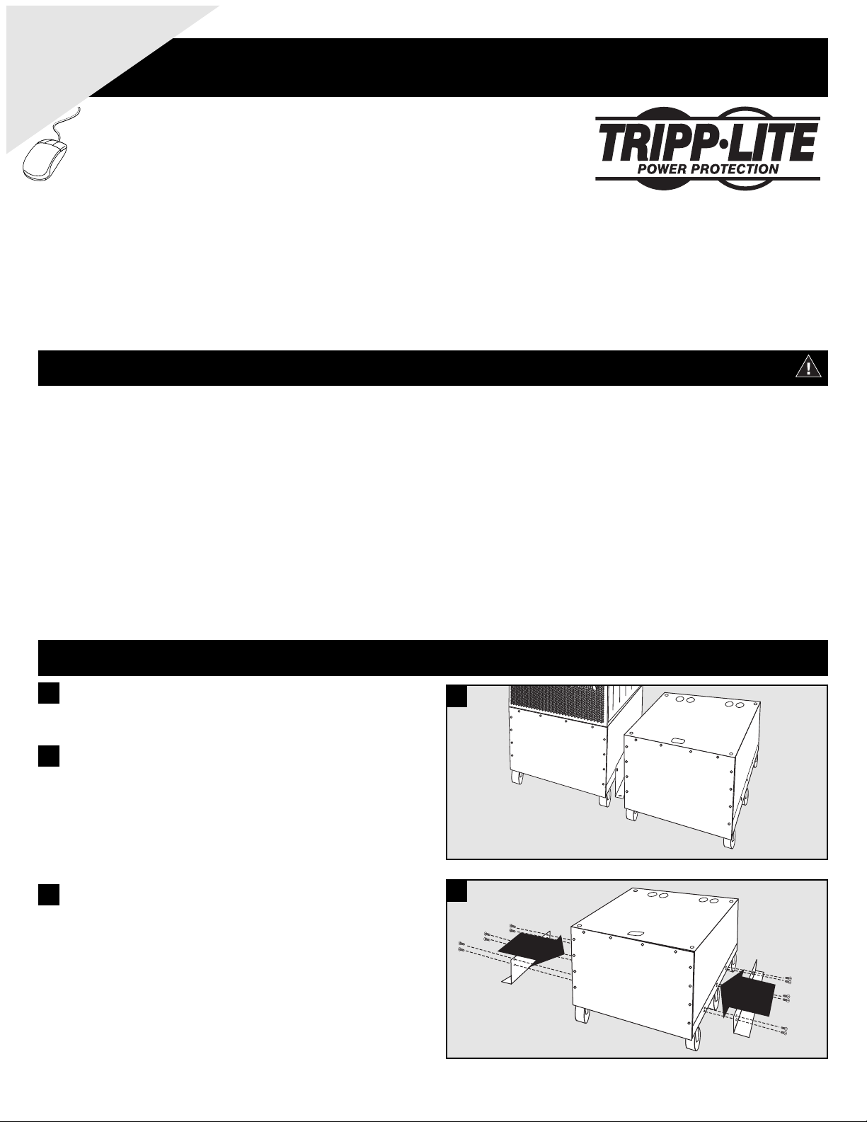
1
Position the battery module compartment next to the UPS system (or next to
another battery module compartment in a daisy-chain connection). Make sure
that the included cable can reach.
2
2
3
Using the included bolts, install one mounting bracket on each side of the
battery module compartment, as shown. If desired, install the bracket to the
floor surface with user-supplied hardware. If the mounting brackets are not
attached to the floor, ensure the rear caster wheels are locked to prevent the
SUBF2030 from rolling and causing a potential hazard.
3
Page 2
DANGER!
RISK OF PRODUCT DAMAGE AND SERIOUS PERSONAL INJURY!
The battery module compartment's wheels are not designed to provide long-term support after final installation. MOUNTING
BRACKET INSTALLATION IS REQUIRED. If the mounting brackets are not installed, the wheels may eventually fail and
potentially damage the battery module compartment and cause serious personal injury.
Installation
(continued)
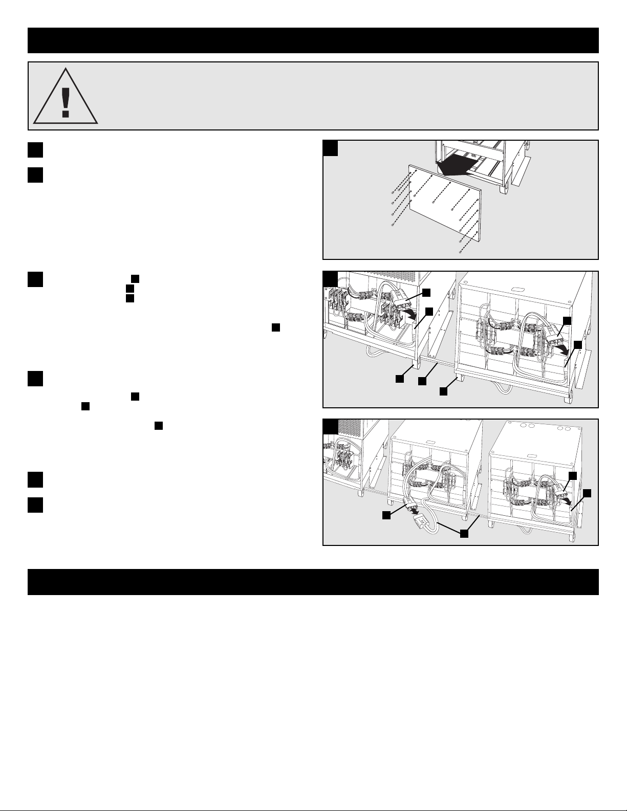
4
Remove the battery module compartment's access panel.
4
Add internal battery packs, fuse block brackets and fuses to the standalone
battery module compartment. See “Adding or Replacing Internal Batteries” in
the UPS system's owner's manual. Ensure that the battery cable connectors are
not covered.
5
Using the included cable , connect one end to the UPS system's external
battery cable connector and the other end to the SUBF2030's external
battery cable connector . To reach the internal connectors, run the cable
through the access slots located on the bottom panel of the UPS system and
SUBF2030 (not shown). To keep the cable away from the front of the UPS, run
it behind the front caster wheels of the UPS system and SUBF2030 . If the
mounting brackets are not attached to the floor, ensure the rear caster wheels
are locked to prevent the wheels from running over the cable.
D
C
B
A
6
6
Replace battery module compartment's access panel.
8
Return the UPS system to Normal Mode or completely turn it on, depending on
the procedure you followed in step 1. See UPS system owner's manual for
instructions.
9
7
OPTIONAL DAISY-CHAIN CONNECTION: Connect additional SUBF2030
compartments in a daisy-chain configuration for additional extended runtime.
Using the included cable , connect one end to the external battery cable
connector located in the upper, middle section of the SUBF2030 located
closest to the UPS system. Connect the other end of the included cable to the
external battery cable connector located in the lower, right corner of the
SUBF2030 located farthest from the UPS system. Daisy-chain additional
SUBF2030 compartments, side-by-side, in the same manner. Do not stack
SUBF2030 models on top of each other.
C
B
A
7
D
A
B
D
A
A
C
A
A
C
B
Warranty & Warranty Registration
LIMITED WARRANTY
Seller warrants this product, if used in accordance with all applicable instructions, to be free from original defects in material and workmanship for a period of 2 years (except U.S., Canada and Mexico: 1 year)
from the date of initial purchase. If the product should prove defective in material or workmanship within that period, Seller will repair or replace the product, in its sole discretion. Service under this Warranty
includes parts and Tripp Lite service center labor. Onsite service plans are available from Tripp Lite through authorized service partners (in most areas). Contact Tripp Lite Customer Service at (773) 869-1234 for
details. International customers should contact Tripp Lite support at intlservice@tripplite.com
THIS WARRANTY DOES NOT APPLY TO NORMAL WEAR OR TO DAMAGE RESULTING FROM ACCIDENT, MISUSE, ABUSE OR NEGLECT. SELLER MAKES NO EXPRESS WARRANTIES OTHER THAN
THE WARRANTY EXPRESSLY SET FORTH HEREIN. EXCEPT TO THE EXTENT PROHIBITED BY APPLICABLE LAW, ALL IMPLIED WARRANTIES, INCLUDING ALL WARRANTIES OF MERCHANTABILITY
OR FITNESS, ARE LIMITED IN DURATION TO THE WARRANTY PERIOD SET FORTH ABOVE; AND THIS WARRANTY EXPRESSLY EXCLUDES ALL INCIDENTAL AND CONSEQUENTIAL DAMAGES.
(Some states do not allow limitations on how long an implied warranty lasts, and some states do not allow the exclusion or limitation of incidental or consequential damages, so the above limitations or exclusions
may not apply to you. This Warranty gives you specific legal rights, and you may have other rights which vary from jurisdiction to jurisdiction).
Tr ipp Lite; 1111 W. 35th Street; Chicago IL 60609; USA
WARNING: The individual user should take care to determine prior to use whether this device is suitable, adequate or safe for the use intended. Since individual applications are subject to great variation, the
manufacturer makes no representation or warranty as to the suitability or fitness of these devices for any specific application..
WARRANTY REGISTRATION
Visit www.tripplite.com/warranty today to register the warranty for your new Tripp Lite product. You'll be automatically entered into a drawing for a chance to win a FREE Tripp Lite product!*
* No purchase necessary. Void where prohibited. Some restrictions apply. See website for details.
Regulatory Compliance Identification Numbers
For the purpose of regulatory compliance certifications and identification, your Tr ipp Lite product has been assigned a unique series number. The series number can be found on the product nameplate label,
along with all required approval markings and information. When requesting compliance information for this product, always refer to the series number.The series number should not be confused with the marking
name or model number of the product.
Tr ipp Lite follows a policy of continuous improvement. Product specifications are subject to change without notice.
200701108
93-2653
 Loading...