

Page 1
PROTECT YOUR
INVESTMENT!
Owner’s Manual
1
Completed and signed start-up forms
MUST be submitted and approved
by Tripp Lite to activate your warranty.
SmartOnline™ 3-Phase UPS System
Model: SU80K
Input/Output: 120/208V AC, 50/60 Hz, 3Ø, 4-wire + ground, wye
Not suitable for mobile applications.
2
3
4
5
6
7
8
9
10
11
12
13
1111 W. 35th Street, Chicago, IL 60609 USA
(773) 869-1234 • www.tripplite.com
Copyright © 2008 Tripp Lite. All trademarks are the sole property of their respective owners.
1
200803004 93-2793 SU80k manual 4C.indd E1200803004 93-2793 SU80k manual 4C.indd E1 6/16/2008 1:43:06 PM6/16/2008 1:43:06 PM
Page 2
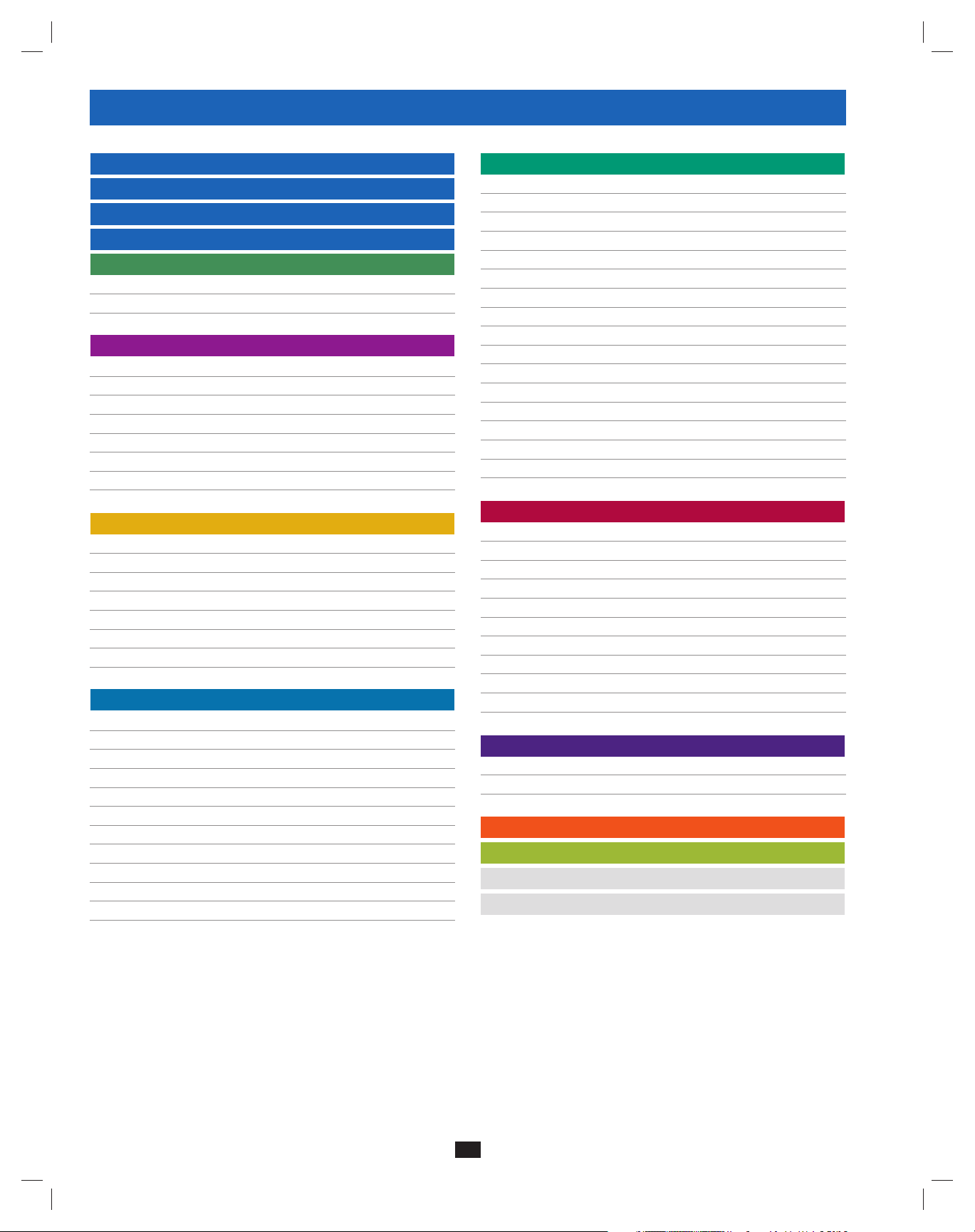
Table of Contents
1
1 Introduction 3
2 Important Safety Instructions 4
2
3 Control Panel Features 6
4 Front and Rear Panel Features 7
5 Cabinet Installation 9
3
5-1 Preparation 9
5-2 Unpacking 9
5-3 Placement 10
6 Wiring 11
4
6-1 Wiring Warnings 11
6-2 Wiring Preparation 11
6-3 UPS System Terminal Block Diagram 12
6-4 External Battery Cabinet Wiring Diagrams 12
5
6-5 Electrical and Cable Data 13
6-6 External Battery Cabinet Wiring 14
6-7 AC Input/Output Wiring (Single UPS) 15
6-8 AC Input/Output Wiring (Parallel UPS – Single Input) 16
6
7 Operating Modes 17
7-1 Online (Normal) Mode (Single UPS) 17
7-2 Battery Backup Mode (Single UPS) 17
7
7-3 Auto Bypass Mode (Single UPS) 17
7-4 Manual Bypass Mode (Single UPS) 17
7-5 Online Mode (Parallel UPS) 18
7-6 Battery Backup Mode (Parallel UPS) 18
8
7-7 Auto Bypass Mode (Parallel UPS) 18
7-8 Manual Bypass Mode (Parallel UPS) 19
8 Start-Up, Shutdown and Bypass 20
8-1 Control Panel and Breaker Diagrams 20
9
8-2 Preliminary Checklist (Single UPS) 20
8-3 Normal Start-Up Procedure (Single UPS) 20
8-4 Battery Start-Up Procedure (Single UPS) 21
8-5 Manual Bypass Procedure (Single UPS) 22
10
8-6 Shutdown Procedure (Single UPS) 22
8-7 Preliminary Checklist (Parallel UPS) 23
8-8 Start-Up Procedure (Parallel UPS) 23
8-9 Shutdown Procedure (Parallel UPS) 24
11
8-10 Manual Bypass Procedure (Parallel UPS) 25
8-11 Switching from Manual Bypass to Normal (Parallel UPS) 26
9 Display and Confi guration 27
9-1 Control Panel Diagram 27
9-2 Display Hierarchy 27
9-3 Default Display 27
9-4 Status Messages and Diagrams 28
9-5 Main Menu 30
9-6 UPS System “Measure” Menu 30
9-7 UPS System Setup Menu 31
9-8 Bypass Setup Menu 31
9-9 Output Setup Menu 32
9-10 Battery Setup Menu 33
9-11 Local Setup Menu 35
9-12 Maintenance Menu 36
9-13 Statistics Menu 37
9-14 Event Log Menu 38
9-15 Manual Setup & Test Menu 39
9-16 Firmware Upgrade Menu 40
9-17 Other Menu Choices 40
10 Communications 41
10-1 Communications Interfaces 41
10-2 SNMPWEBCARD Slot 41
10-3 Input Dry Contact Interface 41
10-4 Remote Emergency Power Off (EPO) Circuit Diagram 42
10-5 Auxiliary Dry Contact Input Circuit Diagram 42
10-6 External Battery Cabinet Temperature Inputs 42
10-7 External Battery Status Input 42
10-8 Output Dry Contact Interface Detail 43
10-9 Output Dry Contact Circuit Diagram 44
10-10 RS-232 Serial Port Circuit Diagram 45
10-11 Parallel Redundancy Port 45
11 Specifi cations 46
11-1 UPS System Technical Specifi cations 46
11-2 UPS System Floor Loading Table 46
11-3 Battery Pack Floor Loading Table 46
12 Storage and Service 47
13 Warranty and Warranty Registration 47
Español 48
Français 95
12
13
2
200803004 93-2793 SU80k manual 4C.indd E2200803004 93-2793 SU80k manual 4C.indd E2 6/16/2008 1:43:07 PM6/16/2008 1:43:07 PM
Page 3
1 – Introduction
Tripp Lite’s SmartOnline 3-Phase UPS Systems are ideal for backing up and protecting data centers, telecommunications (VoIP), networks,
industrial facilities, security/emergency systems and more.
1
Advanced Features:
True on-line double conversion with superior IGBT inverter technology•
Low input current THD allows 1:1 generator sizing for maximum efficiency and cost savings•
Internal N+1 power module redundancy•
Built-in parallel redundancy (1+1) capability for increased capacity or fault-tolerance•
Up to 80kVA capacity in a compact footprint; up to 160kVA in parallel redundancy (1+1) configuration•
High input power factor and high efficiency with low thermal loss and low noise•
Simplified, easy-to-repair, long-life, high-availability system design•
Redundant auxiliary power and control circuits•
All models support external battery cabinets for extended battery backup runtime•
High-resolution LCD status screen simplifies operation and delivers detailed operational information, including system block diagrams•
2
3
4
5
6
7
8
9
10
11
12
13
3
200803004 93-2793 SU80k manual 4C.indd E3200803004 93-2793 SU80k manual 4C.indd E3 6/16/2008 1:43:07 PM6/16/2008 1:43:07 PM
Page 4

2 – Important Safety Instructions
1
SAVE THESE INSTRUCTIONS
All sections of this manual contains instructions and warnings that should be followed during the installation and operation of the UPS
2
systems described in this manual. Read all instructions thoroughly before attempting to move, install or operate the UPS systems described in
this manual. Failure to comply may invalidate the warranty and cause property damage and/or personal injury.
Location Warnings
3
Install the UPS system in a controlled indoor environment, away from moisture, temperature extremes, flammable liquids and gasses, conductive •
contaminants, dust and direct sunlight.
Install the UPS system in a • level, structurally sound location.
4
The UPS system is extremely heavy; be extremely careful when moving or lifting the unit.•
Operate the UPS system at indoor temperatures between 32° F and 104° F (0° C and 40° C) only. For best results, maintain indoor temperatures •
between 62° F and 84° F (17° C and 29° C).
Leave adequate space around all sides of the UPS system for proper ventilation. Do not block, cover or insert objects into the external ventilation •
5
openings of the cabinet.
Do not place any object on the unit, especially containers of liquid.•
Do not mount the unit with its front or rear panel facing down (at any angle). Mounting in this manner will seriously inhibit the unit’s internal •
cooling, eventually causing product damage not covered under warranty.
6
Do not install the UPS system near magnetic storage media, as this may result in data corruption. Keep all recorded magnetic media a minimum •
of 60 cm (24 inches) away from the UPS system.
Do not attempt to stack the UPS system. Attempting to stack the UPS system may cause permanent damage and create a potential for serious •
personal injury.
7
The casters are designed for minor position adjustments within the final installation area only. The casters are not designed for moving the UPS •
system over longer distances.
The casters are not designed to provide long-term support for the UPS system after final installation. Use the levelers to provide long-term •
support.
8
When moving the UPS system, push from the front or rear, not from the sides.•
Do not attempt to unpack or move the UPS system without assistance.•
Connection Warnings
9
The power supply for this unit must be three-phase rated in accordance with the equipment nameplate. It also must be suitably •
grounded according to all applicable local electrical wiring regulations.
The UPS system contains hazardous high voltages that have the potential to cause personal injury or death from electric shock.•
10
11
12
The UPS system has its own energy source (battery – internal and/or external). The output terminals may be live even when the UPS system is •
not connected to an AC supply.
If the UPS system receives power from a motor-powered AC generator, the generator must provide clean, filtered, computer-grade output.•
Use of this equipment in life support applications where failure of this equipment can reasonably be expected to cause the failure of the life •
support equipment or to significantly affect its safety or effectiveness is not recommended. Do not use this equipment in the presence of a
flammable anesthetic mixture with air, oxygen or nitrous oxide.
The UPS system is designed to power modern computer loads and associated peripheral devices. Do not use the UPS system to power pure •
inductive or capacitive loads.
Input and output wiring should be performed by trained, qualified electricians only.•
Due to high leakage current, a proper earth ground connection is essential before connecting the AC supply.•
Isolate the UPS system before working on the circuit. An easily accessible disconnect device should be incorporated in the fixed wiring. The •
disconnect device must be a 4-pole device and must disconnect all line conductors and the neutral conductor.
13
4
200803004 93-2793 SU80k manual 4C.indd E4200803004 93-2793 SU80k manual 4C.indd E4 6/16/2008 1:43:08 PM6/16/2008 1:43:08 PM
Page 5

2 – Important Safety Instructions (continued)
Battery Warnings
The UPS system does not require routine maintenance. There are no user-serviceable parts inside. Only qualified service personnel should open •
the access panels for any reason.
Batteries present a risk of electrical shock and burns from high short-circuit current. Battery connection or replacement should be performed •
only by qualified service personnel, observing proper precautions. Turn off the UPS system before connecting or disconnecting internal
batteries. Use tools with insulated handles. Do not open the batteries. Do not short or bridge the battery terminals with any object.
Replace batteries with equivalent batteries available from Tripp Lite. Do not operate the UPS system without batteries.•
The batteries are recyclable. Refer to local codes for disposal requirements.•
Do not dispose of the batteries in a fire, mutilate the batteries or open the battery coverings.•
Battery fuses should be replaced by qualified service personnel only. Blown fuses must be replaced with the same number and type of fuses. •
Potentially lethal voltages exist within the UPS system as long as the battery supply is connected. Service and repair should be performed •
by trained personnel only, while the UPS system is turned off or placed into bypass mode. Disconnect internal batteries (if present) before
performing any service work by switching off the internal battery circuit breaker and removing the battery fuse(s). Disconnect external batteries
(if present) by switching off the external battery cabinet breaker and disconnecting the external battery cabling from the UPS system.
Do not connect or disconnect batteries when the UPS system is operating from the battery supply or when the unit is not in bypass mode.•
Do not remove the plastic sleeves covering internal batteries.•
Internal and external batteries must be replaced by equivalent batteries available from Tripp Lite.•
Before connecting an external battery cabinet to the UPS system, read the external battery cabinet’s documentation. Use only external battery •
cabinets that have been approved by Tripp Lite.
If the UPS system remains off for an extended period of time, it should be turned on periodically to allow the batteries to recharge. The UPS •
system should be turned on and the batteries should be recharged at least one uninterrupted 24-hour period every 3 months. Failure to recharge
the batteries periodically may cause irreversible battery damage.
Wiring Warnings
See • Section 6-1 for wiring warnings
1
2
3
4
5
6
7
8
9
10
11
12
13
5
200803004 93-2793 SU80k manual 4C.indd E5200803004 93-2793 SU80k manual 4C.indd E5 6/16/2008 1:43:08 PM6/16/2008 1:43:08 PM
Page 6
3 – Control Panel Features
1
A E F G H I J KBCD
2
3
4
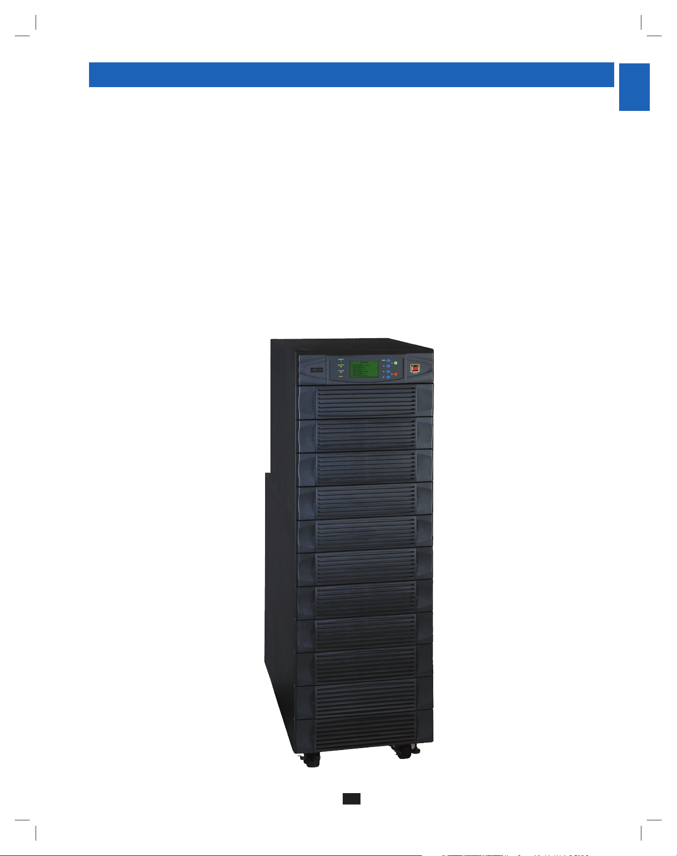
“NORMAL” LED:• This green light illuminates to indicate that the UPS system is in online (normal) mode. The primary AC input supply is
A
present and within standard operating parameters.
“BATTERY” LED:• This amber light illuminates when the UPS system is in battery backup mode, discharging the batteries to provide power
B
5
6
7
8
9
10
11
12
to connected equipment. An audible alarm will also sound.
“BYPASS” LED:• This amber light illuminates when the UPS system is in bypass mode (auto bypass or manual bypass). Battery backup
C
power will not be available to connected equipment while the UPS system is in bypass mode, but connected equipment loads will be
supported by the bypass power source.
“FAULT” LED:• This red light illuminates when any UPS system or input power fault occurs. Available diagnostic information will be
D
displayed on the LCD screen.
LCD Status Screen:• This illuminated LCD status screen displays text and graphics to indicate a wide range of UPS system operating
E
conditions and diagnostic data. Note: The LCD backlight will turn off after 10 minutes of inactivity. Turn on the backlight by momentarily
pressing the ON button or one of the scroll buttons.
“ESC” (Escape) Button:• Press this button to return to the previous page or menu.
F
G
Scroll Buttons (• and ): Press these buttons to move the cursor up or down and navigate the control panel menus and screens. These
buttons are also used for data entry in several screens.
Enter Button (• ): Press this button to select a menu item or confirm a setting change.
H
ON Button:• Press and hold this button for 3 seconds to turn the UPS system’s inverter ON.
I
J
OFF Button:• Press and hold this button for 3 seconds to turn the UPS system’s inverter OFF. If the UPS system is in online (normal) mode,
it will switch to auto bypass mode. Note: If the UPS system remains off for an extended period of time, the batteries should be recharged
periodically. The UPS system should be turned on and the batteries should be recharged at least one uninterrupted 24-hour period every
3 months. Failure to recharge the batteries periodically may cause irreversible battery damage.
“EPO” (Emergency Power Off) Button:• Press this button to turn the UPS system’s output OFF and also disable bypass output.
K
If the UPS system is in battery backup mode when the EPO button is activated:
Main output and bypass output are turned off, the alarm sounds, fans shut down after approximately one minute, and control circuitry •
remains active.
Releasing the EPO button (by pressing it again) turns off the UPS system completely, including the alarm and control circuit. Press the •
ON button for 3 seconds to restart the UPS system.
If the UPS system is in online (normal) mode when the EPO button is activated:
Main output and bypass output are turned off, the alarm sounds, fans and control circuitry remain active.•
Releasing the EPO button (by pressing it again) turns off the alarm and places the UPS system in auto bypass mode. Press the ON button •
for 3 seconds to return the UPS system to online (normal) mode.
See Section 9 – Display and Configuration for detailed information about the control panel’s menus and displays.
13
6
200803004 93-2793 SU80k manual 4C.indd E6200803004 93-2793 SU80k manual 4C.indd E6 6/16/2008 1:43:08 PM6/16/2008 1:43:08 PM
Page 7
4 – Front and Rear Panel Features
A
1
2
B
4
5
3
C
6
7
8
D
E
SU80K shown (front)
Note: Individual models may vary from diagrams. Unit shown with front bezels removed.
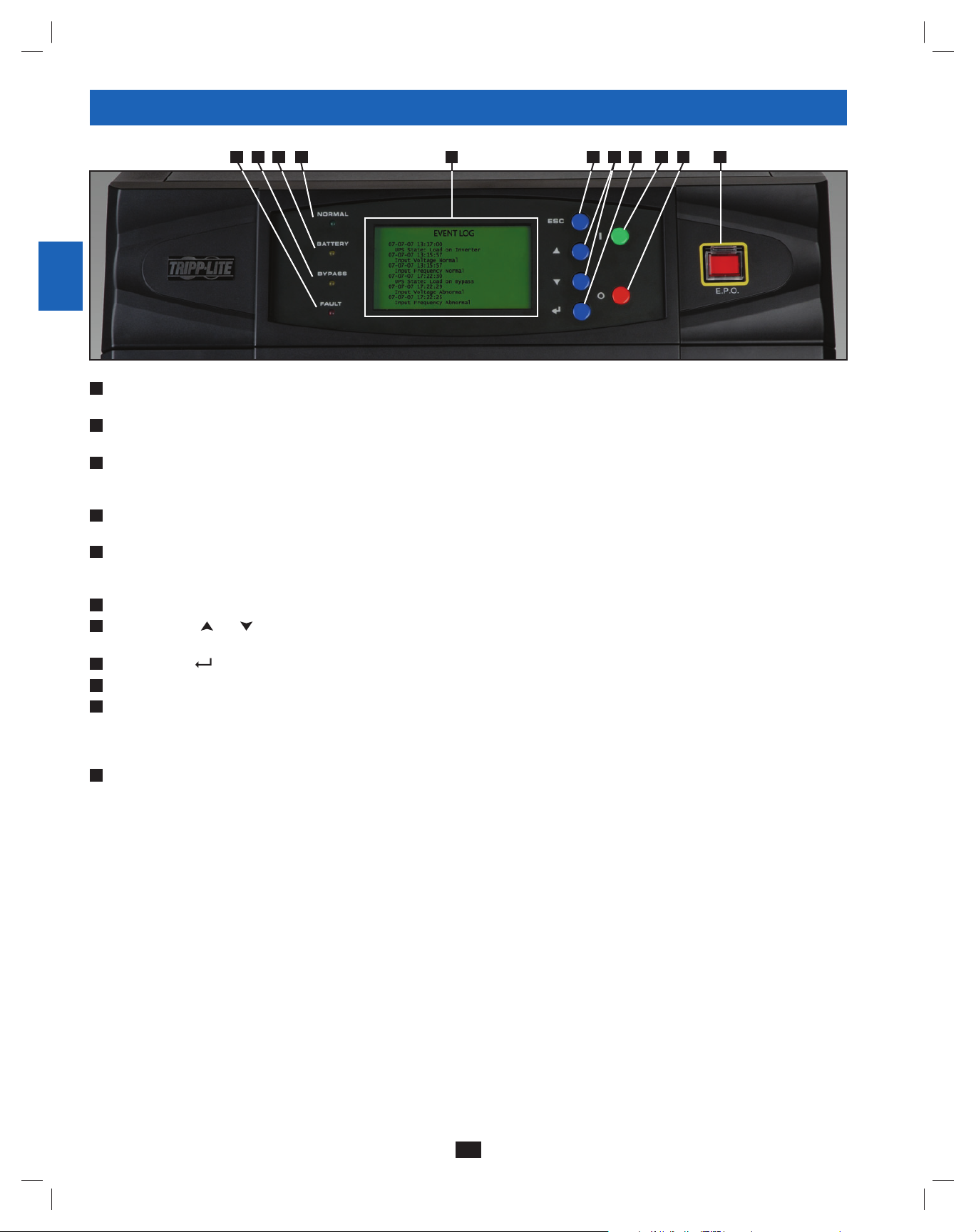
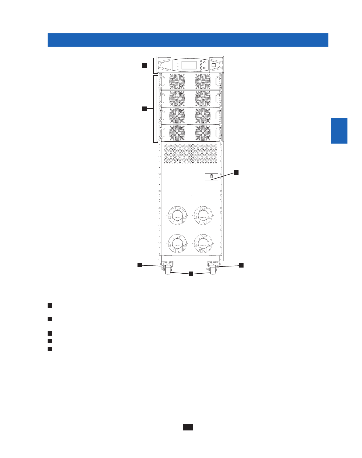
Control Panel:• The control panel allows the operator to monitor and control the UPS system. See Section 3 – Control Panel Features for
A
more information.
B
Internal Power Modules:• 20kVA internal power modules can be replaced in the field without powering down connected equipment loads.
The number of internal power modules varies by model. The internal power modules are capable of N+1 redundancy.
Main Input Circuit Breaker Switch (Q1):• Controls AC input power to the UPS system during online (normal) operation.
C
D
Levelers:• The levelers provide long-term support for the UPS system.
E
Casters:• The casters are designed for small position adjustments within the final installation location only; they are not designed for moving
the UPS system over longer distances. The casters are not designed to provide long-term support for the UPS system after final installation.
Use the levelers to provide long-term support.
D
9
10
11
12
13
7
200803004 93-2793 SU80k manual 4C.indd E7200803004 93-2793 SU80k manual 4C.indd E7 6/16/2008 1:43:09 PM6/16/2008 1:43:09 PM
Page 8
4 – Front and Rear Panel Features (continued)
1
H
2
3
4
5
F
I
G
J
L
M N
6
7
8
D
SU80K shown (rear)
Note: Individual models may vary from diagrams. Unit shown with breaker guard removed.
9
D
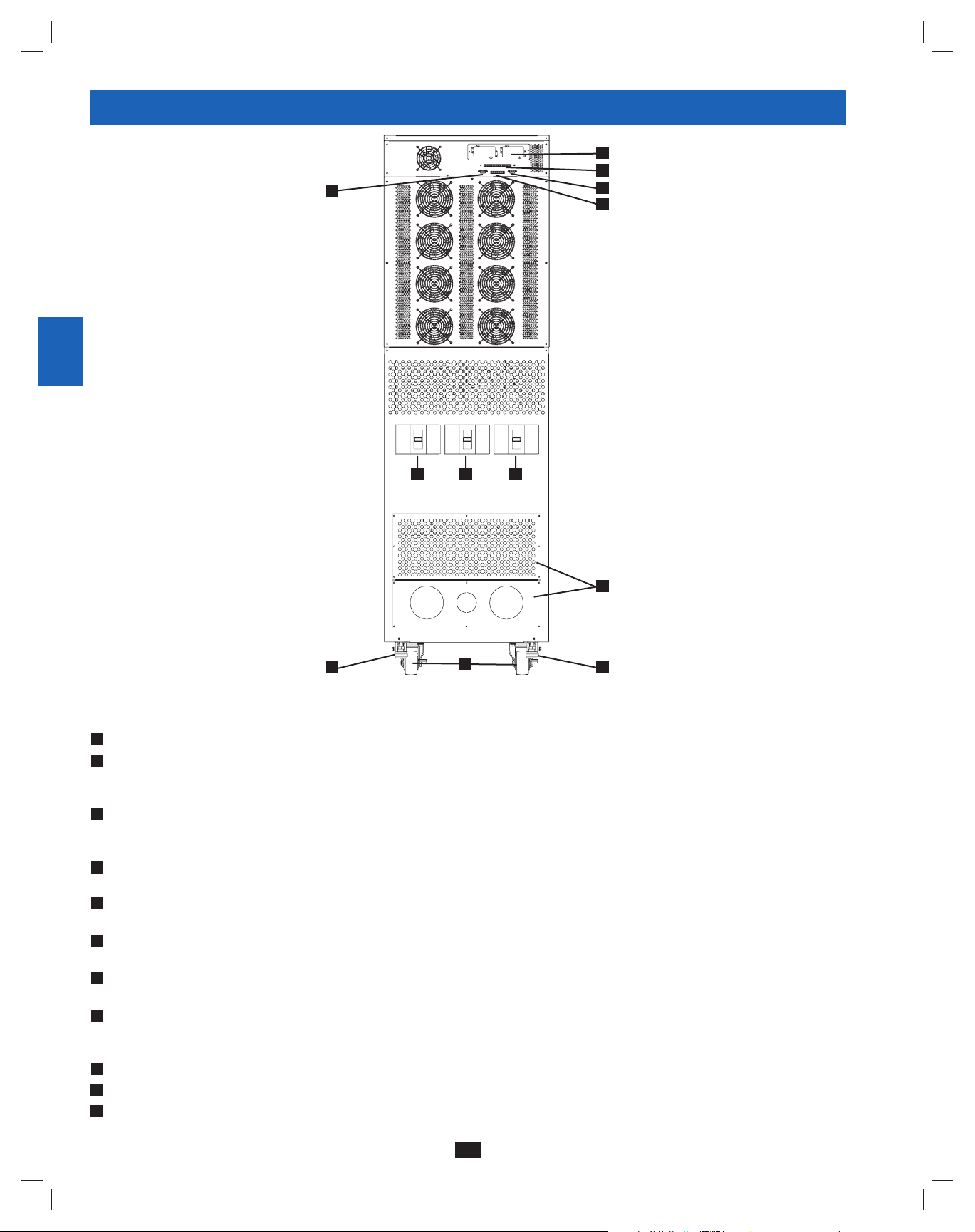
Levelers:• The levelers provide long-term support for the UPS system.
E
Casters:• The casters are designed for small position adjustments within the final installation location only; they are not designed for moving
the UPS system over longer distances. The casters are not designed to provide long-term support for the UPS system after final installation.
10
11
12
13
Use the levelers to provide long-term support.
F
Accessory Slot:• Remove the cover panel to install a Tripp Lite SNMPWEBCARD accessory. The SNMPWEBCARD accessory provides an
Ethernet interface for the UPS system and enables remote monitoring and control via SNMP, Web browser or telnet. Call (773) 869-1234 for
more information about the SNMPWEBCARD accessory.
G
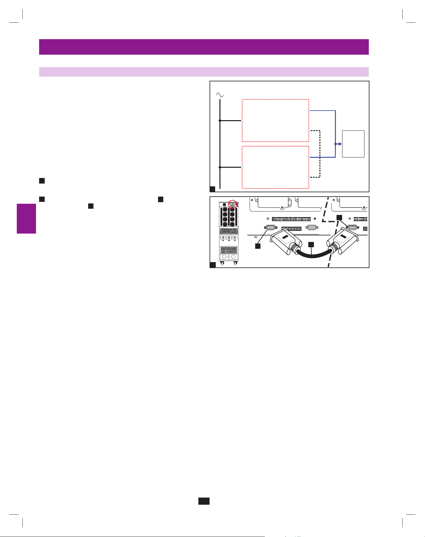
RS-232 Serial Communications Port:• This DB9 port connects the UPS system to compatible workstations or servers, enabling automatic
shutdown during extended blackouts and monitoring of operating and power conditions.
H
Parallel Redundancy Port:• This DB9 port connects the UPS system to another UPS system of identical type and capacity for use in a
parallel redundancy (1+1) configuration. See Section 6 – Wiring and Section 7 – Operating Modes for more information.
I
Input Dry Contact Interface:• This interface receives dry contact signals that allow the UPS system to receive commands and monitor
external battery conditions. See Section 10 - Communications for more information.
J
Output Dry Contact Interface:• This interface allows the UPS system to send information via dry contact communications. See Section 10 –
Communications for more information.
K
Terminal Block Cover:• Remove the terminal block cover to access the UPS system’s input, external battery cabinet, output and grounding
connection terminals. Wiring conduits pass through the circular knockouts in the terminal block cover. The UPS system includes alternate
circular knockouts in the bottom panel. See Section 6 – Wiring for more information, including a detailed diagram of the terminal block.
L
Bypass Input Circuit Breaker Switch (Q2):• Controls AC input power to the UPS system during auto bypass operation.
M
Manual Bypass Circuit Breaker Switch (Q3):• Controls AC input power to the UPS system during manual bypass operation.
N
Output Circuit Breaker Switch (Q4):• Controls AC output power.
E
K
D
8
200803004 93-2793 SU80k manual 4C.indd E8200803004 93-2793 SU80k manual 4C.indd E8 6/16/2008 1:43:09 PM6/16/2008 1:43:09 PM
Page 9
5 – Cabinet Installation
1
Read Section 2 – Important Safety Instructions Before Installation
5-1 Preparation
The UPS system must be installed in a structurally sound area with a level floor that is able to bear the weight of the UPS system, any external
battery cabinet and other equipment that will be installed nearby. The installation site should also have a dedicated AC circuit available that is
compatible with the UPS system’s input requirements. (See Section 11 – Specifications for details on input requirements and floor loading
requirements.) Before unpacking the unit, you should transport the shipping container closer to the final installation site to minimize the distance
you will need to move the unit after the protective shipping container has been removed. If you plan to store the UPS system for an extended
period before installation, follow the instructions in Section 12 – Storage and Service. (Unpacking and storage instructions are also printed on the
“Unpacking and Storage Instructions” sheet secured to the shipping container.) Warning: Do not attempt to unpack or move the UPS system
without assistance.
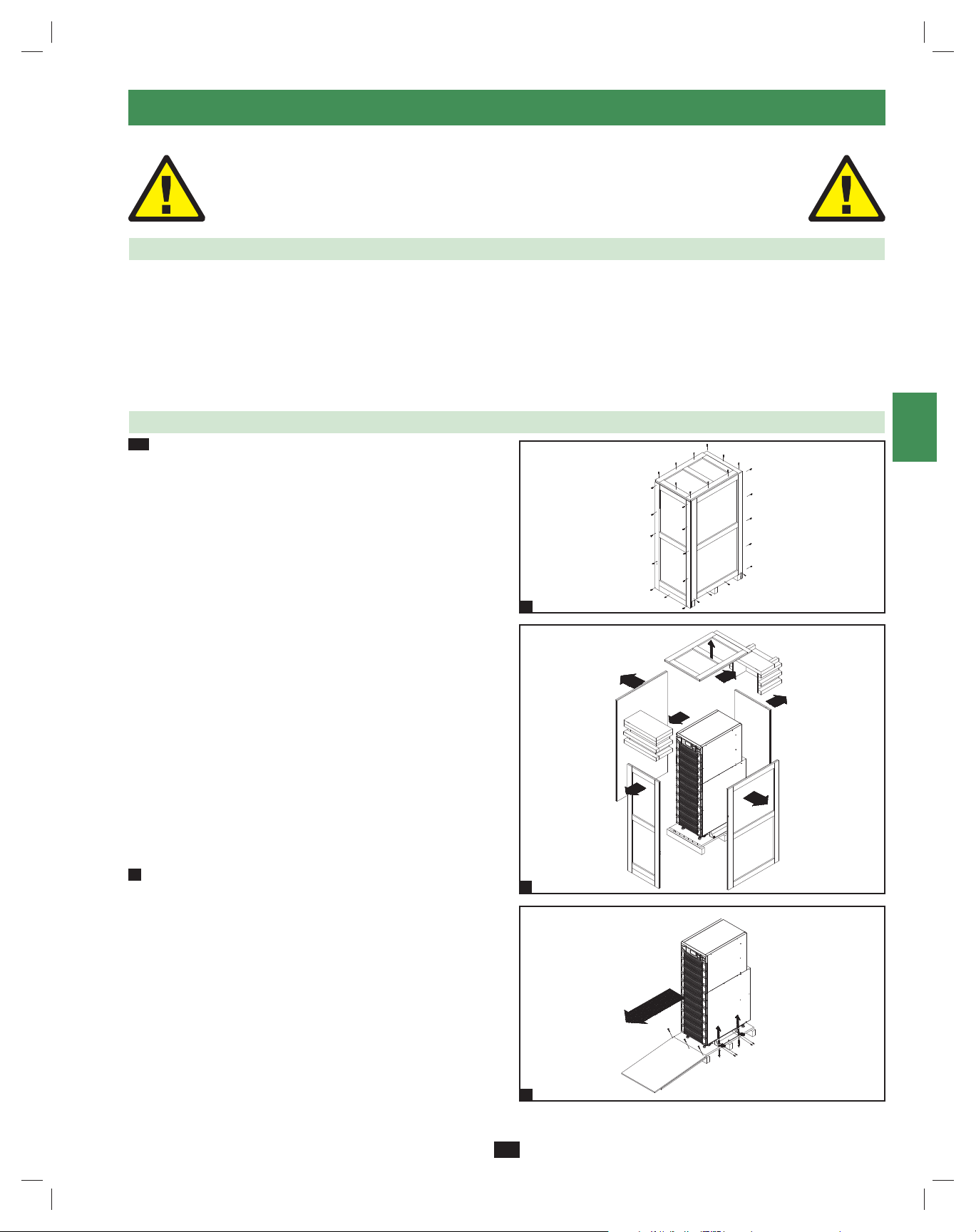
5-2 Unpacking
1-2
Inspect the shipping container(s) for visible damage. If you •
determine that the unit has been damaged during shipping, contact
Tripp Lite for assistance. Do not attempt to use the UPS system if
it has been damaged or mishandled.
Confirm that the shipping container is upright and use a
screwdriver to remove its top panel, front panel and back panel.
Also remove the plastic wrap and interior cushioning material.
Confirm that the model name and rating at the rear of the cabinet
match the unit you ordered. Examine the cabinet for any damaged
or loosened parts. Confirm that the shipping container includes the
accessories that ship with the unit. The UPS system should include
an RS-232 serial cable, a parallel redundancy cable, a remote EPO
wiring connector, a dry contact input connector (4 contacts), a dry
contact output connector (12 contacts) and a software CD-ROM. If
anything is missing or damaged, contact Tripp Lite for assistance.
Confirm that the unit is stable, then remove the side panels from
the shipping container.
1
2
3
4
5
6
7
8
Remove the bolts from the shipping brackets securing the unit •
3
to the pallet, then remove the shipping brackets from the UPS
system. Warning: Be extremely careful, as the unit could shift
unexpectedly.
Use several of the screws you removed in step 1 to attach the top
panel of the shipping container to the front edge of the shipping
pallet. The smooth surface of the panel should face upward so
that it can be used as a ramp for rolling the unit off the shipping
pallet. Do not attempt to use the top panel as a ramp if it is cracked
or otherwise structurally damaged. Make sure the casters at the
bottom of the unit are unlocked. Using extreme caution, slowly roll
the unit down the ramp with the aid of several assistants.
9
10
2
11
12
13
3
9
200803004 93-2793 SU80k manual 4C.indd E9200803004 93-2793 SU80k manual 4C.indd E9 6/16/2008 1:43:10 PM6/16/2008 1:43:10 PM
Page 10
5 – Cabinet Installation (continued)
1
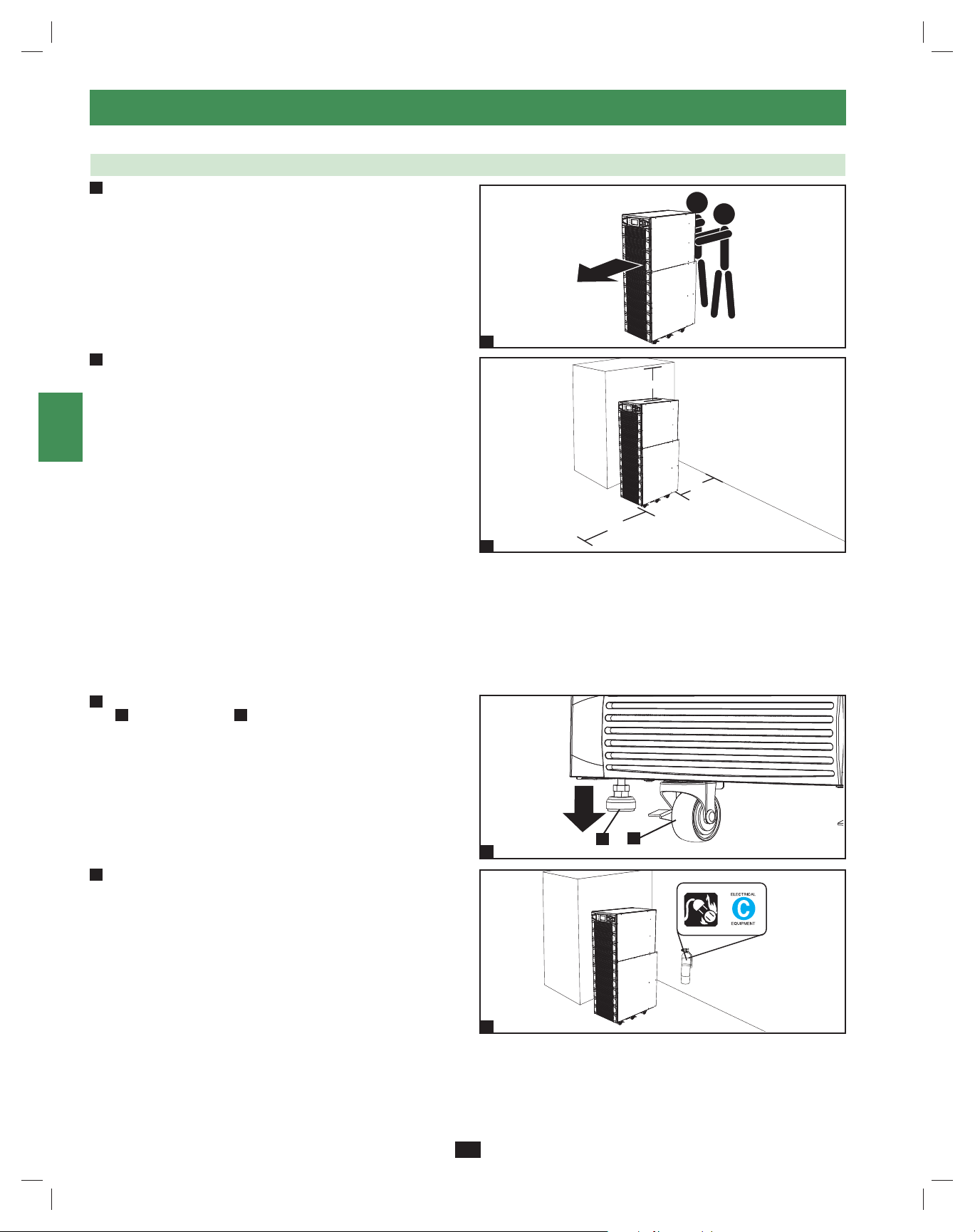
5-3 Placement
Use the casters to move the UPS system for a short distance over •
1
2
3
4
5
6
7
8
9
a level, smooth, stable surface. Do not attempt to use the casters
to move the UPS system over longer distances. The UPS system
should be moved close to its final installation location inside
its shipping container before it is unpacked from the shipping
container. Use a mechanical device of sufficient capacity to move
the shipping container. Warning: The UPS system could tip if it
is moved over an unstable surface. Be extremely careful when
moving the UPS system. Push the UPS system from the front or
rear, not from the sides.
2
Position the UPS system in a structurally sound area with a •
level floor that is able to bear the weight of the UPS system,
any external battery cabinets and other equipment that will
be installed nearby. The installation site should also have a
dedicated AC circuit available that is compatible with the UPS
system’s input requirements. (See Section 11 – Specifications
for more information about input requirements and floor loading
requirements.) The UPS system must be installed in a clean,
secure environment with a relative humidity less than 90% (noncondensing). Operate the UPS system at indoor temperatures
between 17° C and 29° C (62° F and 84° F). Prevent damage to
cabling by using suitable protective conduits. In order to maintain
proper airflow and service access, you must maintain the following
clearances:
At least 100 cm clearance in front of the UPS system.•
At least 50 cm clearance behind the UPS system.•
At least 50 cm clearance above the UPS system.•
Warning: The cooling fans circulate air from front to back. Do not
use any air conditioning or fan that blows air directly toward the
rear of the UPS system.
After moving the UPS system to its final location, lock the casters •
3
A
and use the levelers B to stabilize the cabinet. Ensure that all
four levelers make firm contact with the floor.
1
50 cm
50 cm
100 cm
2
10
A
B
11
For emergency use, install a fire extinguisher rated for energized •
4
electrical equipment fires (Class C rating or exact equivalent, with
a non-conductive extinguishing agent) near the UPS system.
3
12
13
200803004 93-2793 SU80k manual 4C.indd E10200803004 93-2793 SU80k manual 4C.indd E10 6/16/2008 1:43:10 PM6/16/2008 1:43:10 PM
4
10
Page 11

6 – Wiring
DANGER! LETHAL HIGH VOLTAGE HAZARD!
All wiring should be performed by a qualifi ed electrician, in accordance with the warnings in this manual and all applicable
electrical and safety codes. Incorrect wiring may damage the UPS system severely and cause serious personal injury and
property damage. Read
Section 2 – Important Safety Instructions before proceeding.
1
2
6-1 Wiring Warnings
De-energize all input and output power sources of the UPS system before installing cables or making electrical connections.•
Use flexible cable of sufficient length to permit UPS system servicing. The maximum cable length is 10 m (32.8 ft).•
Use ferrule caps to cover termination cables and prevent frayed ends from shorting on the UPS system terminal block.•
Use cabling rated VW-1, FT-1 or better.•
Use cable sleeves and connector clamps.•
The neutral conductor must be the same size as the current conductors.•
Tighten all connections with a torque of at least 3.95 N·m (35 in·lb)•
Confirm that all cables are marked correctly according to their purpose, polarity, phase and diameter.•
If the UPS system’s input/output power source is wye-wye, then “Neutral” and “Ground” must not be connected.•
If the input power source has V•
system’s “Neutral” and “Ground” together.
For equipment requiring a neutral connection to an IT power distribution system, the disconnect device must be a four-pole device and must •
disconnect all line conductors and the neutral conductor. If a disconnect device interrupts the neutral conductor, it must simultaneously interrupt
all line conductors.
Allow the batteries to charge uninterrupted for 24 hours after the initial wiring connection.•
Observe proper polarity by connecting negative to negative and positive to positive. Failure to observe proper polarity will damage the UPS •
system and create a serious risk of personal injury and property damage.
Observe proper phase by connecting R to R, S to S, T to T and N to N. Failure to observe proper phase will damage the UPS system and create a •
risk of personal injury and property damage.
>0, install an isolation transformer before the UPS system and input power source, then connect the UPS
NG
3
4
5
6
7
8
6-2 Wiring Preparation
De-energize all input and output (AC and DC) of the UPS system and external battery cabinet (if present).•
Mark all cables according to their correct purpose, polarity, phase and diameter.•
Review the diagrams in • Section 6-3 and Section 6-4 to familiarize yourself with the terminal blocks.
Consult the table in • Section 6-5 to find the correct electrical input/output characteristics for the UPS system.
Note: If the UPS system’s input/output power source is wye-wye, then “Neutral” and “Ground” must not be connected. If the input power
source has VNG>0, install an isolation transformer before the UPS system and input power source, then connect the UPS system’s “Neutral” and
“Ground” together.
9
10
11
12
13
11
200803004 93-2793 SU80k manual 4C.indd E11200803004 93-2793 SU80k manual 4C.indd E11 6/16/2008 1:43:11 PM6/16/2008 1:43:11 PM
Page 12
6 – Wiring (continued)
1
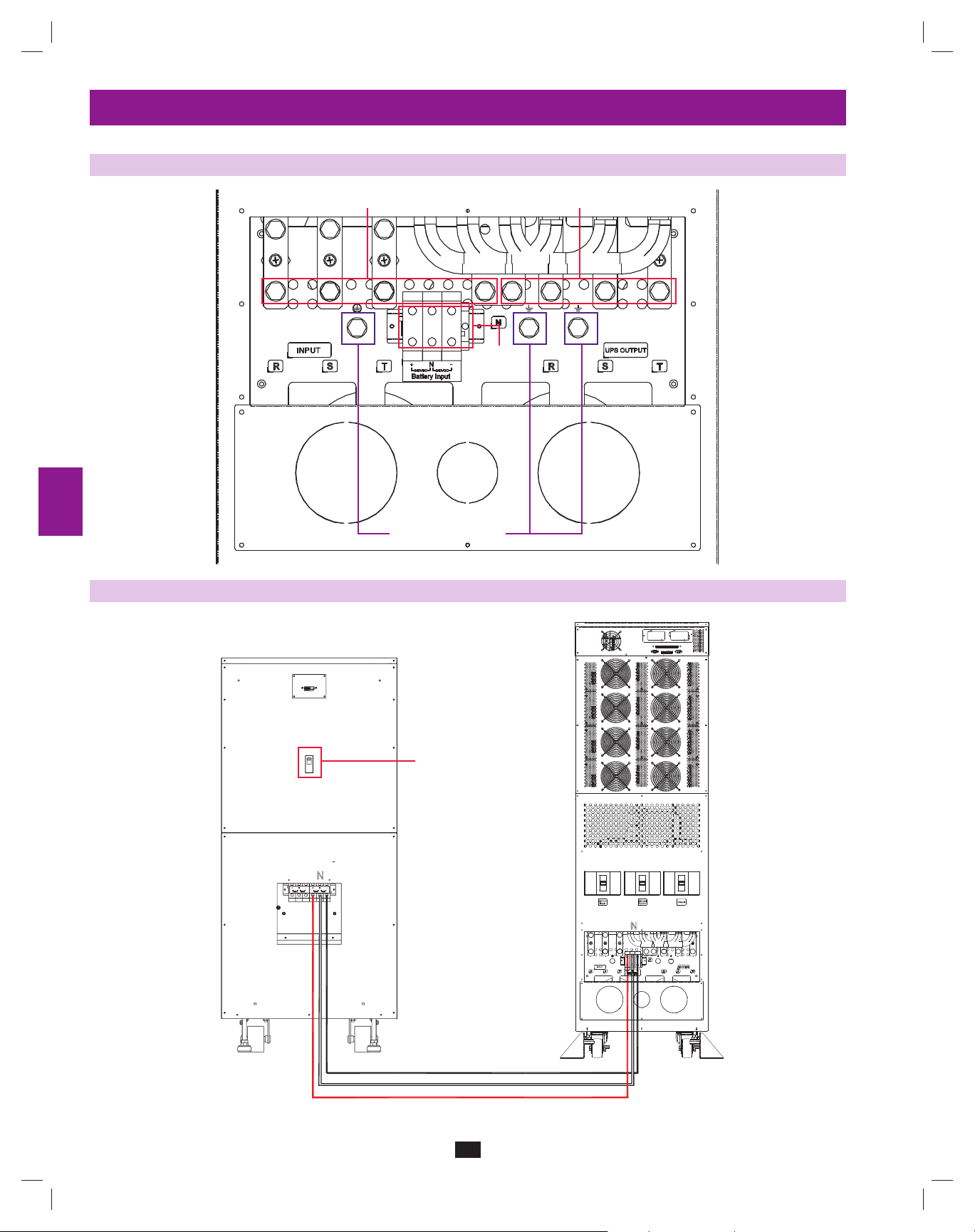
6-3 UPS System Terminal Block Diagram
2
Input
3
4
5
6
7
6-4 External Battery Cabinet Wiring Diagrams
Output
External
Battery
Connection
Grounding Terminals
10
11
12
13
8
9
External Battery
Cabinet Breaker
Switch
+ –
+
–
SU80K and BP480V40C shown for illustration only; consult the battery cabinet’s documentation for exact specifications
12
200803004 93-2793 SU80k manual 4C.indd E12200803004 93-2793 SU80k manual 4C.indd E12 6/16/2008 1:43:11 PM6/16/2008 1:43:11 PM
Page 13
6 – Wiring (continued)
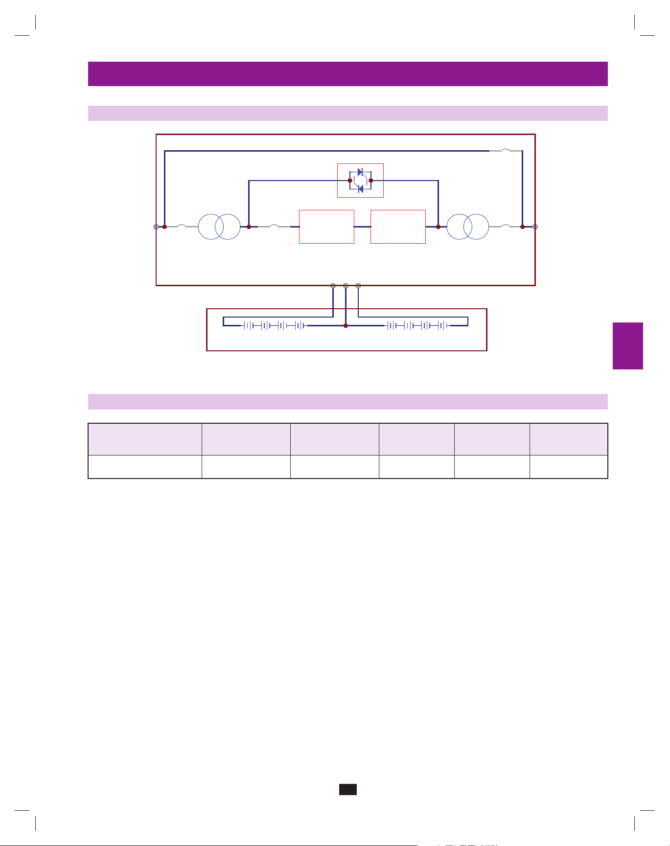
T
6-4 External Battery Cabinet Wiring Diagrams (continued)
1
XFMR XFMR
UPS
B+ N B-
External Battery Cabinet
B Cabinet: 26AH per Battery
C Cabinet: 40AH per Battery
6-5 Electrical and Cable Data
Q1Q2
12V, 20 Batteries 12V, 20 Batteries
AC/DCMAIN INPUT
B+ B-N
DC/AC
Q3
Q4
2
3
OUTPU
4
5
6
7
Input and Output Battery Input and Output Battery
Model Input/Output Breaker Size Fuse Size Cable Size Cable Size
SU80K 120/208V AC, 3Ø, 300A 220A 4/0 AWG 2 AWG
4-wire + ground, wye
8
9
10
11
12
13
13
200803004 93-2793 SU80k manual 4C.indd E13200803004 93-2793 SU80k manual 4C.indd E13 6/16/2008 1:43:13 PM6/16/2008 1:43:13 PM
Page 14
6 – Wiring (continued)
1
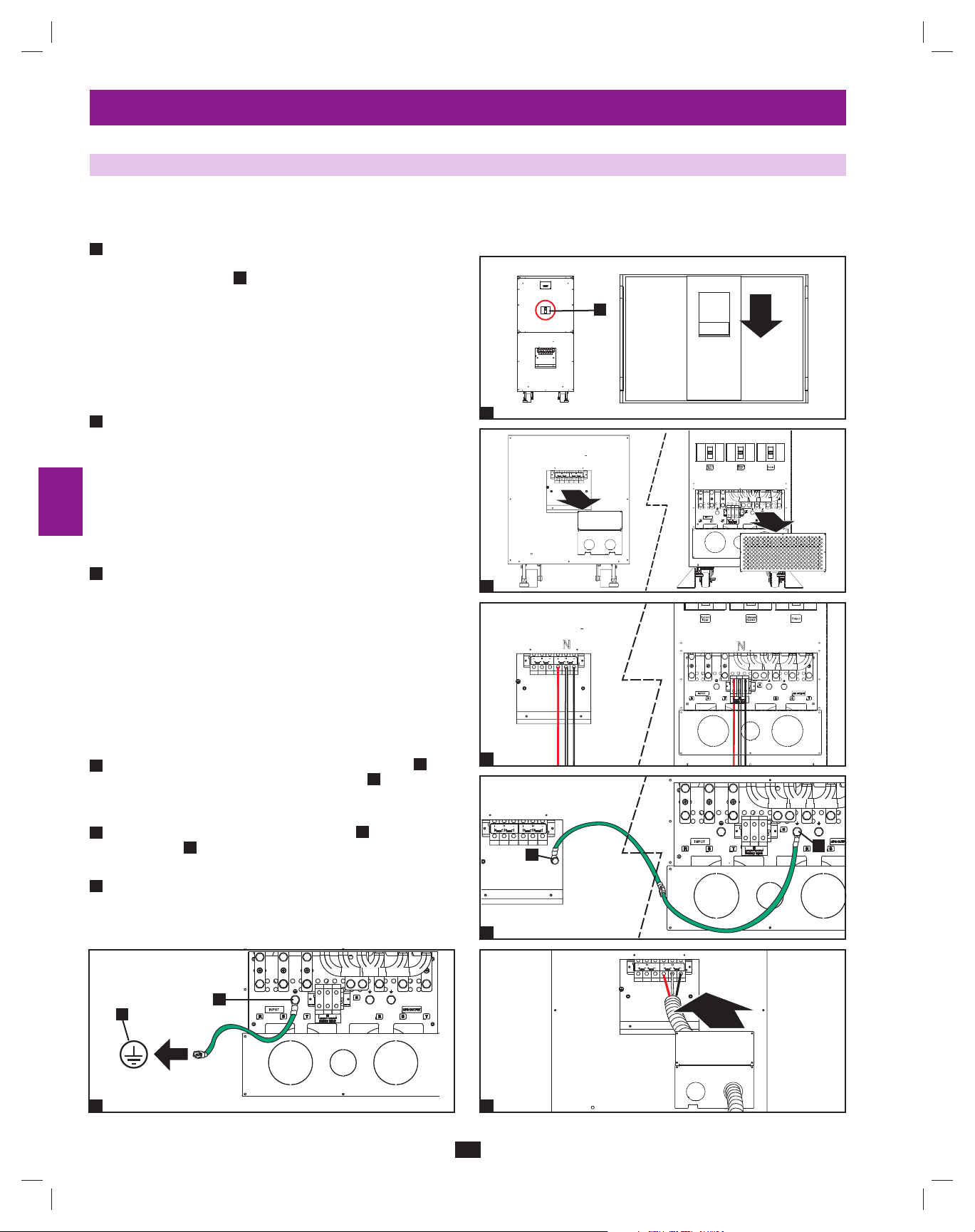
6-6 External Battery Cabinet Wiring
Warning: External battery cabinets vary. Read the external battery cabinet’s documentation before attempting to connect it to the UPS
2
system. Use only external battery cabinets that have been approved by Tripp Lite.
Note: An external battery cabinet is required. Contact Tripp Lite for external battery cabinet ordering information.
De-energize all input and output (AC and DC) of the UPS system •
1
and external battery cabinet, and confirm that the external battery
A
3
cabinet breaker switch
been wired to an AC power source, see
instructions.)
4
is off. (If the UPS system has already
Section 8-6 for shutdown
A
10
11
5
external battery cabinet.
Remove the terminal block covers from the UPS system and •
2
1
6
Connect the positive (+), neutral (N) and negative (-) UPS •
3
7
8
9
system connection terminals of the external battery cabinet to the
corresponding positive (+), neutral (N) and negative (-) external
battery connection terminals of the UPS system. See Section 6-3
and the external battery cabinet’s documentation for terminal
block diagrams. See Section 6-4 for wiring diagrams. See Section
6-5 for cable size requirements. Cabling should be protected by
flexible conduit and routed through the appropriate knockouts in
the terminal block cover. Warning: Observe proper polarity by
connecting negative to negative and positive to positive. Failure
to observe proper polarity will damage the UPS system and
create a risk of personal injury and property damage.
Connect the external battery cabinet’s grounding terminal•
4
UPS system’s corresponding grounding terminal
(5.189 mm) ground cable. Keep the ground cable connected at all
times after installation.
Connect the UPS system’s grounding terminal•
5
earth ground
ground cable connected at all times after installation.
Replace the terminal block cover of the external battery cabinet. If •
6
you do not plan to wire the AC input/output of the UPS system at
this time, replace the terminal block cover of the UPS system.
with a 4 AWG (5.189 mm) ground cable. Keep the
B
with a 4 AWG
B
to your facility’s
A
A
to the
2
+ –
3
A
4
+
–
B
12
A
B
13
65
14
200803004 93-2793 SU80k manual 4C.indd E14200803004 93-2793 SU80k manual 4C.indd E14 6/16/2008 1:43:13 PM6/16/2008 1:43:13 PM
Page 15
6 – Wiring (continued)
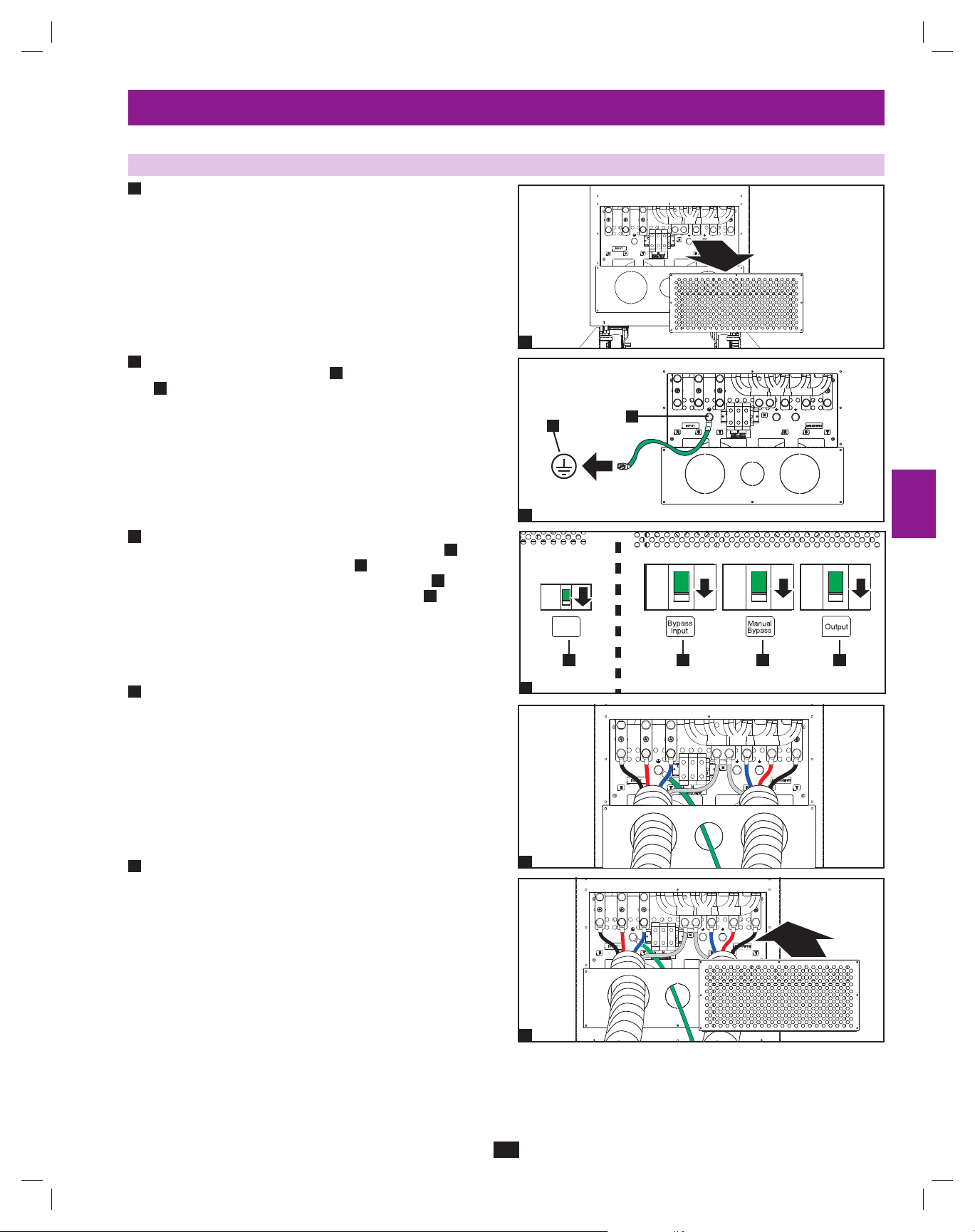
6-7 AC Input/Output Wiring (Single UPS)
After de-energizing all input and output (AC and DC) of the UPS •
1
system, remove the terminal block cover from the UPS system.
1
2
3
If you did not connect the ground cable in •
2
UPS system’s grounding terminal
B
with a 4 AWG (5.189 mm) ground cable. Keep the ground cable
Section 6-6, connect the
A
to your facility’s earth ground
connected at all times after installation.
Remove the UPS system’s front bezel to expose the circuit breaker. •
3
First, confirm that the main input circuit breaker switch
the bypass input circuit breaker switch
are both off. Second,
B
confirm that the manual bypass circuit breaker switch
Third, confirm that the output circuit breaker switch
Confirm the phase of each cable, then connect the cables according •
4
to the UPS system terminal block diagram in
Section 6-3. See
D
A
C
is off.
Section 6-5 for cable size requirements. Cabling should be
protected by flexible conduit and routed through the appropriate
knockouts in the terminal block cover. Warning: Observe proper
phase by connecting R to R, S to S, T to T and N to N. Failure
to observe proper phase will damage the UPS system and
create a risk of personal injury and property damage.
and
is off.
1
4
B
2
Front Panel
3
OFF
Main
Input
O
A
A
5
6
O
OFF
B C D
O
OFF
Back Panel
OFF
O
7
8
9
10
Replace the UPS system’s terminal block cover.•
5
4
11
12
5
15
200803004 93-2793 SU80k manual 4C.indd E15200803004 93-2793 SU80k manual 4C.indd E15 6/16/2008 1:43:19 PM6/16/2008 1:43:19 PM
13
Page 16
6 – Wiring (continued)
1
6-8 AC Input/Output Wiring (Parallel UPS – Single Input)
Parallel Redundancy Warnings:
2
3
4
1
5
2
The total input cable length must be equal to the total •
output cable length in order to prevent unbalanced load
sharing between two UPS systems under reserve mode
(i.e. IP1 + OP1 = IP2 + OP2; deviation must be <10%).
Parallel redundancy only supports 2 UPS systems (1+1 •
redundancy ). Do not attempt to link more than two UPS
systems via parallel redundancy.
The UPS systems must have the same rating and capacity •
for parallel redundancy installation. Attempting to link
dissimilar UPS systems will damage the UPS systems
and create a serious risk of personal injury and property
damage.
Follow the steps in •
in the diagram.
Connect the included parallel redundancy cable•
redundancy port
Section 6-7, wiring the UPS systems as shown
A
to the parallel
of each UPS system.
B
1
AC I/P
IP1
IP2
Main I/P
Main I/P
UPS1
UPS2
O/P
Parallel Port
O/P
Parallel Port
OP1
Parallel Cable
Load
OP2
10
11
6
B
A
B
7
2
8
9
12
13
16
200803004 93-2793 SU80k manual 4C.indd E16200803004 93-2793 SU80k manual 4C.indd E16 6/16/2008 1:43:24 PM6/16/2008 1:43:24 PM
Page 17
7 – Operating Modes
This section provides a basic description of the UPS system’s operating modes. For more information about switching between operating modes,
refer to Section 8 – Start-Up, Shutdown and Bypass.
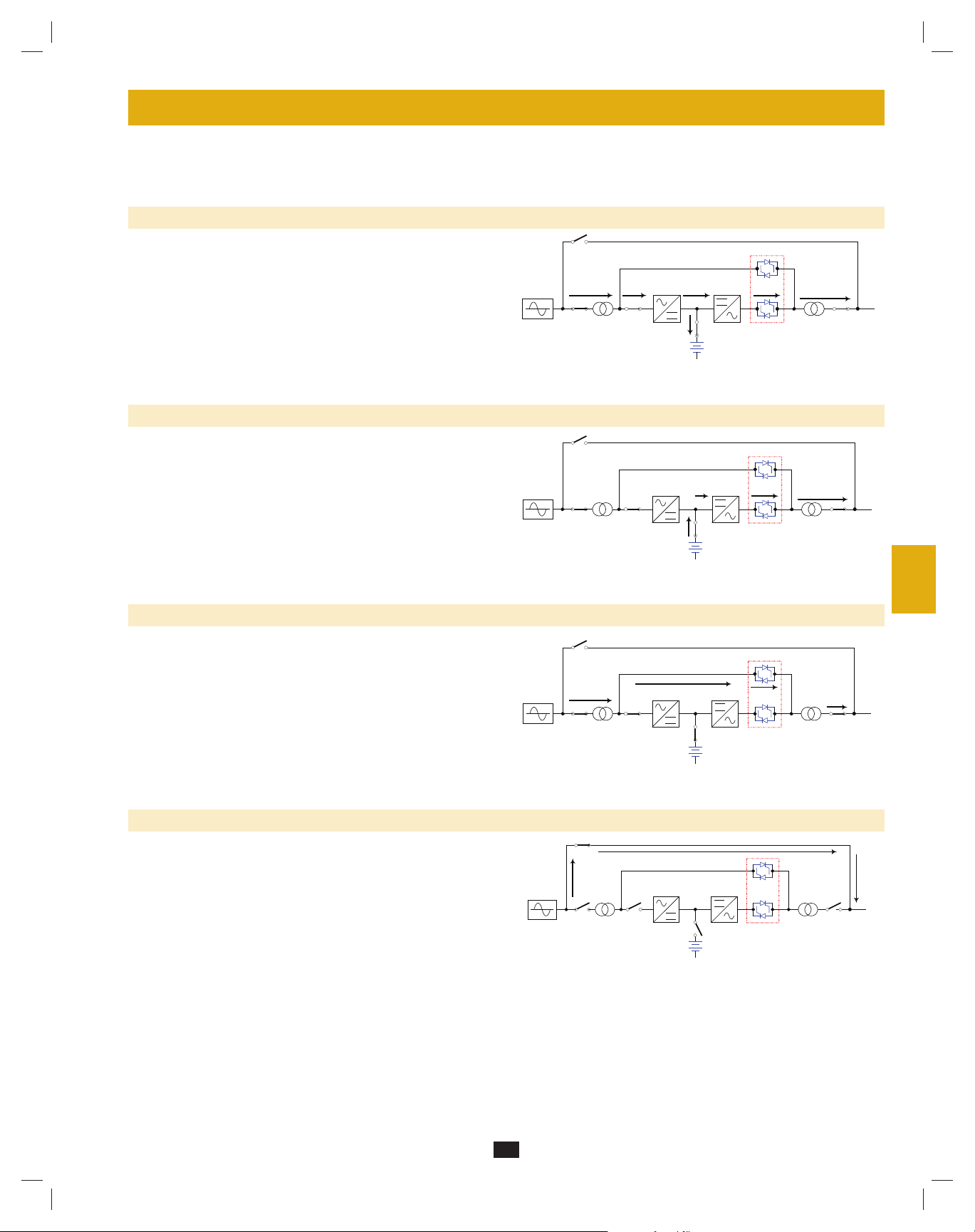
7-1 Online (Normal) Mode (Single UPS)
In online (normal) mode, the UPS system’s rectifier converts incoming
AC utility power to DC power that charges the batteries and supplies the
inverter. The inverter transforms the DC power to precision-regulated,
pure sine wave AC power that supports the operation of connected
equipment. This dual conversion technology isolates connected
equipment from all power problems and ensures that connected
equipment receives ideal power at all times.
MAIN
CB3
CB2
CB1
XFMR XFMR
CB5
STS
CB4
1
2
3
LOAD
4
7-2 Battery Backup Mode (Single UPS)
When a blackout or other extreme power event occurs, the UPS system
automatically switches from normal mode to battery backup mode. The
UPS system’s batteries (internal and/or external) provide emergency
DC power to the inverter. The inverter transforms the DC power
to precision-regulated, pure sine wave AC power that supports the
operation of connected equipment.
7-3 Auto Bypass Mode (Single UPS)
If the inverter malfunctions due to excessive temperature, overload,
output short circuit, abnormal voltage or battery problems, the inverter
will shut down. If the UPS system detects a bypass power source that
conforms to normal parameters, then the UPS system automatically
switches to auto bypass mode to continue supplying power to connected
equipment. When all problems are eliminated, the UPS system switches
back to online (normal) mode automatically.
7-4 Manual Bypass Mode (Single UPS)
If UPS system maintenance or repair is required, you can bypass the
UPS system and enable bypass power manually. After confirming that
bypass power is present, switch the UPS system into manual bypass
mode. This allows service technicians to perform maintenance or repair
jobs without interrupting the flow of AC power to connected equipment.
Warning: The UPS system must be de-energized completely before
performing maintenance or repair by shutting it down completely
after switching it to manual bypass mode.
LOAD
5
6
MAIN
CB3
CB2
CB1
XFMR XFMR
CB5
STS
CB4
7
MAIN
CB3
CB2
CB1
XFMR XFMR
CB5
STS
8
CB4
LOAD
9
10
CB3
11
MAIN
CB2
CB1
XFMR XFMR
CB5
STS
CB4
LOAD
12
13
17
200803004 93-2793 SU80k manual 4C.indd E17200803004 93-2793 SU80k manual 4C.indd E17 6/16/2008 1:43:27 PM6/16/2008 1:43:27 PM
Page 18
7 – Operating Modes (continued)
1
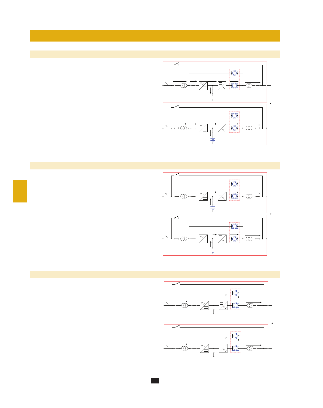
7-5 Online Mode (Parallel UPS)
Parallel redundancy (1+1) provides UPS system redundancy or
increased total capacity. Under parallel redundancy, the total load is
2
shared by two UPS systems. If one of the UPS systems malfunctions,
the total connected equipment load is supported by the remaining UPS
system. If the total load exceeds the capacity of the remaining UPS
system, it will switch to auto bypass mode.
3
4
MAIN
CB3
CB2
CB3
CB1
XFMR XFMR
CB5
STS
CB4
UPS1
LOAD
5
7-6 Battery Backup Mode (Parallel UPS)
6
Similar to on battery backup mode for a single UPS system (Section
7-2), except the total connected equipment load is shared by the parallel
(1+1) UPS systems.
7
8
9
MAIN
MAIN
MAIN
CB2
CB3
CB2
CB3
CB2
CB1
XFMR XFMR
CB1
XFMR XFMR
CB1
XFMR XFMR
CB5
CB5
CB5
STS
STS
STS
CB4
UPS2
CB4
UPS1
LOAD
CB4
UPS2
10
7-7 Auto Bypass Mode (Parallel UPS)
Similar to auto bypass mode for a single UPS system (Section 7-3),
except with parallel (1+1) UPS systems.
CB3
11
12
MAIN
CB2
CB3
CB1
XFMR XFMR
CB5
STS
CB4
UPS1
LOAD
13
MAIN
CB2
CB1
XFMR XFMR
CB5
STS
18
200803004 93-2793 SU80k manual 4C.indd E18200803004 93-2793 SU80k manual 4C.indd E18 6/16/2008 1:43:27 PM6/16/2008 1:43:27 PM
CB4
UPS2
Page 19
7 – Operating Modes (continued)
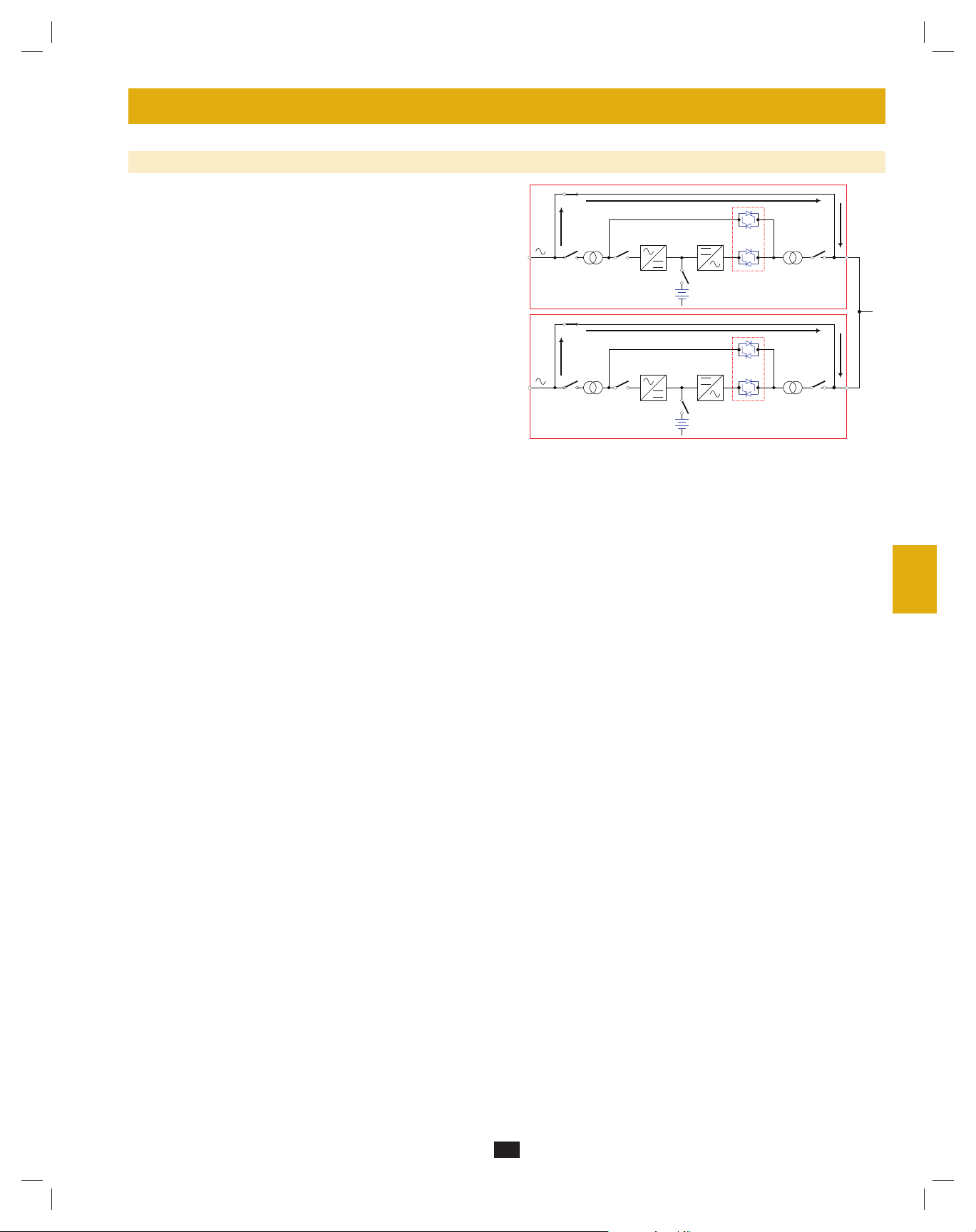
7-8 Manual Bypass Mode (Parallel UPS)
Similar to manual bypass mode for a single UPS system (Section 7-4),
except with parallel (1+1) UPS systems. Note: Both UPS systems must
be switched into manual bypass mode.
1
CB3
2
MAIN
MAIN
CB2
CB3
CB2
CB1
XFMR XFMR
CB1
XFMR XFMR
CB5
CB5
STS
STS
CB4
UPS1
CB4
UPS2
3
LOAD
4
5
6
7
8
9
10
11
12
13
19
200803004 93-2793 SU80k manual 4C.indd E19200803004 93-2793 SU80k manual 4C.indd E19 6/16/2008 1:43:27 PM6/16/2008 1:43:27 PM
Page 20
8 – Start-Up, Shutdown and Bypass
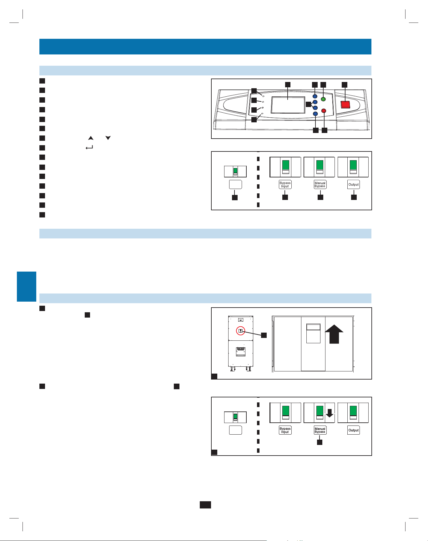
1
8-1 Control Panel and Breaker Diagrams
“NORMAL” LED•
A
2
3
4
5
6
“BATTERY” LED•
B
“BYPASS” LED•
C
“FAULT” LED•
D
LCD Status Screen•
E
“ESC” (Escape) Button•
F
Scroll Buttons (• and )
G
Enter Button (• )
H
ON Button•
I
OFF Button•
J
“EPO” (Emergency Power Off) Button•
K
Output Circuit Breaker Switch•
L
Manual Bypass Circuit Breaker Switch•
M
Bypass Input Circuit Breaker Switch•
N
Main Input Circuit Breaker Switch•
O
O
OFF
Main
Input
O
Front Panel
E
A
B
C
D
Control Panel
O
OFF
Circuit Breaker Switches
F
I
G
J
H
O
OFF
Back Panel
K
O
OFF
LN M
8-2 Preliminary Checklist (Single UPS)
All circuit breaker switches should be off, including the breaker of the external battery cabinet (if present).•
Confirm that no voltage potential exists between Neutral and Ground.•
7
Confirm that the input power source matches the rating (voltage, frequency and phase) of the UPS system.•
Note: After start-up, the UPS system will perform a brief self-test and display the results on the LCD screen. After a successful self-test, the UPS
system will provide AC power to the connected equipment load.
8
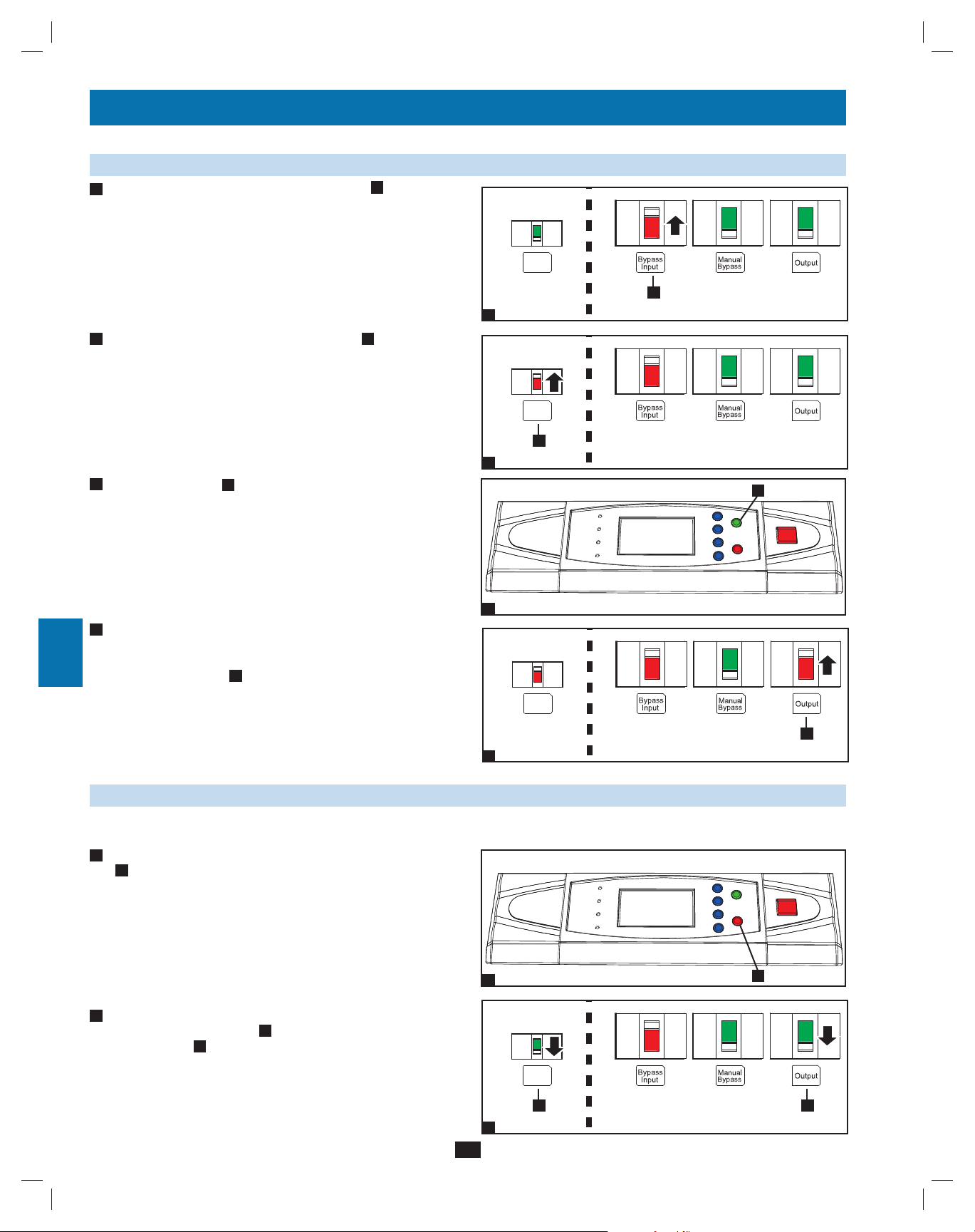
8-3 Normal Start-Up Procedure (Single UPS)
If there is an external battery cabinet connected, switch on the •
1
circuit breaker A of the external battery cabinet.
9
A
10
1
11
12
2
Confirm that the manual bypass circuit breaker switch •
A
is off.
Main
Main
Input
Input
O
O
OFF
O
O
OFF
OFF
OFF
OFF
OFF
O
O
OFF
OFF
O
O
A
13
Front Panel
2
Back Panel
Back Panel
Front Panel
20
200803004 93-2793 SU80k manual 4C.indd E20200803004 93-2793 SU80k manual 4C.indd E20 6/16/2008 1:43:27 PM6/16/2008 1:43:27 PM
Page 21
8 – Start-Up, Shutdown and Bypass (continued)
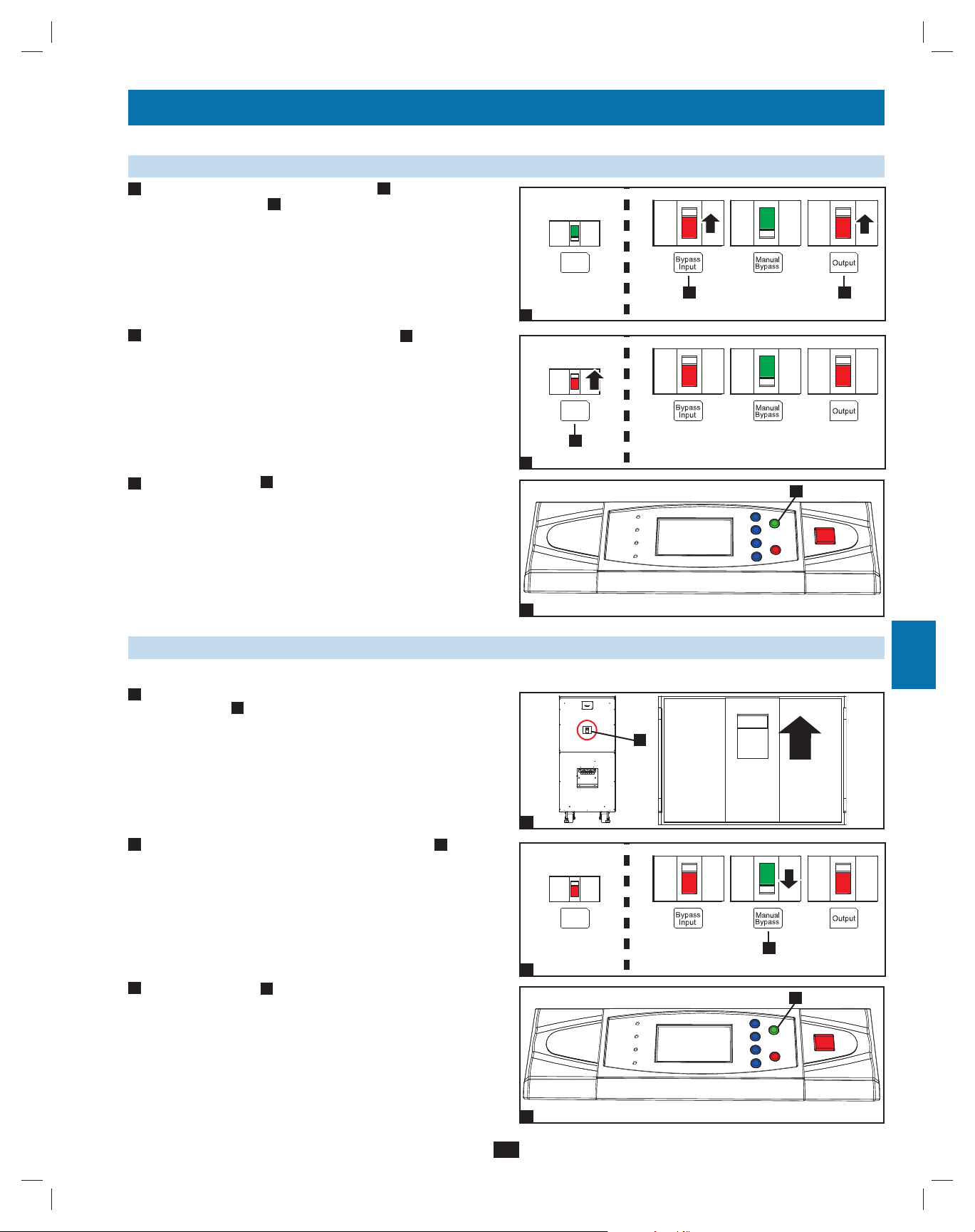
8-3 Normal Start-Up Procedure (Single UPS) (continued)
3
Switch on the output circuit breaker switch •
B
circuit breaker switch
. After a brief initialization process, the
LCD screen will show “ON AUTO BYPASS”, the “BYPASS”
LED will illuminate and UPS system output will be supplied by
the bypass power source.
4
Switch on the main input circuit breaker switch •
power source is normal, the UPS system is ready for start-up.
Press the ON button •
5
A
for 3 seconds (until you hear a beep), then
release the button. The inverter will activate and synchronize with
the bypass source, then automatically switch from auto bypass
mode to online (normal) mode. The “BYPASS” LED will darken
and the “NORMAL” LED will illuminate.
A
and bypass input
A
. If the AC input
Front Panel
3
Front Panel
4
Main
Input
Main
Input
1
O
O
OFF
ON
I
OFF
ON
I
2
3
B A
Back Panel
O
ON
ON
I
I
OFF
ON
I
A
4
5
Back Panel
A
6
5
8-4 Battery Start-Up Procedure (Single UPS)
Note: The battery must be at least partially charged for this operation to succeed.
If there is an external battery cabinet connected, switch on the •
1
circuit breaker A of the external battery cabinet.
1
2
Confirm that the manual bypass circuit breaker switch •
3
Press the ON button •
A
for 3 seconds (until you hear a beep), then
release the button. The inverter will activate and use stored DC
battery power to supply AC power to connected equipment. The
“BATTERY” LED will illuminate.
A
is off.
2
ON
I
Main
Input
Front Panel
7
8
A
9
10
O
ON
I
OFF
ON
I
11
A
Back Panel
12
A
13
3
21
200803004 93-2793 SU80k manual 4C.indd E21200803004 93-2793 SU80k manual 4C.indd E21 6/16/2008 1:43:31 PM6/16/2008 1:43:31 PM
Page 22
8 – Start-Up, Shutdown and Bypass (continued)
1
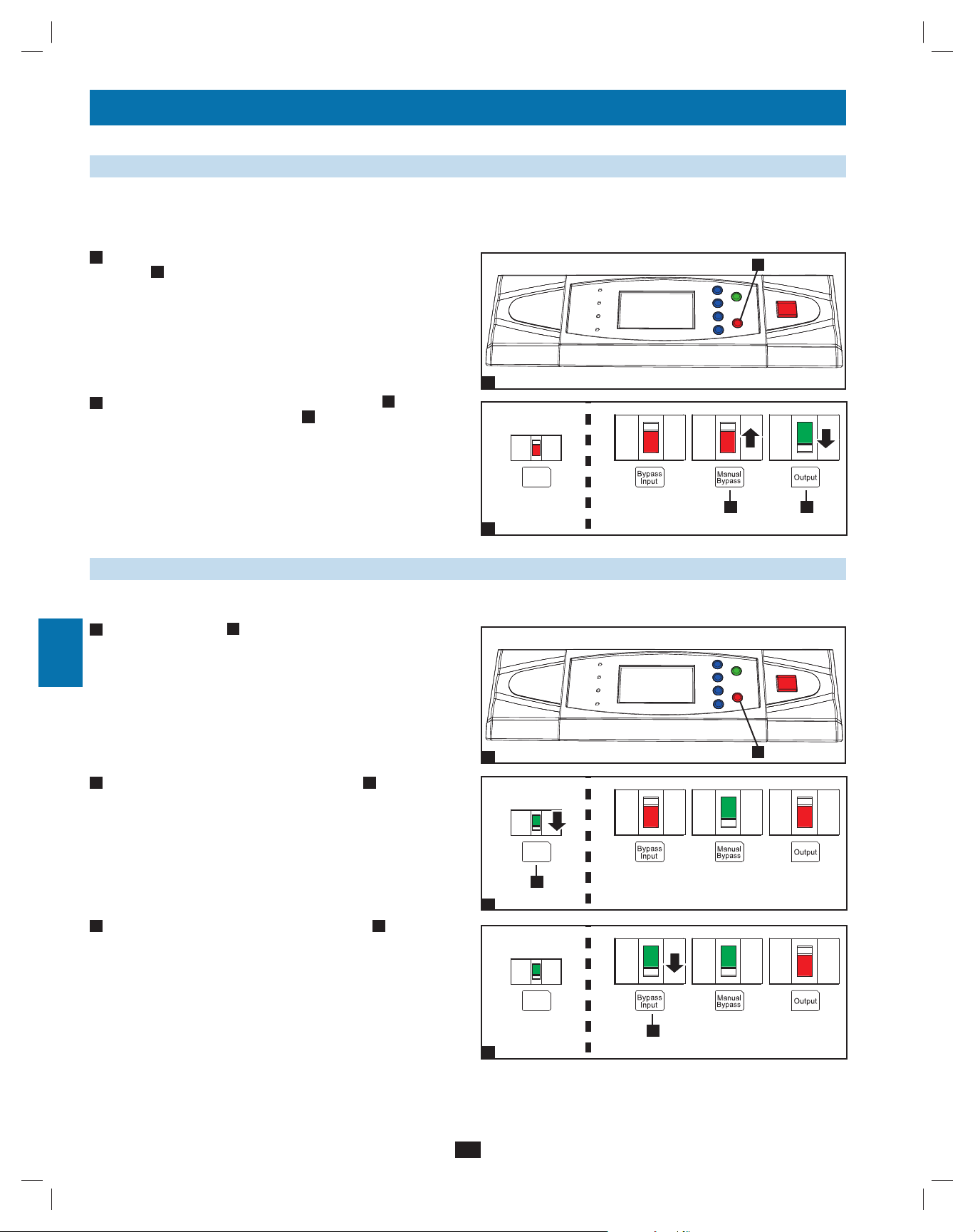
8-5 Manual Bypass Procedure (Single UPS)
Warning: Placing the UPS system in manual bypass will disable the inverter and power all loads from the manual bypass source, but
2
the UPS system will still be energized. Before performing maintenance or repair on the UPS system, shut down and de-energize the UPS
system completely by following the steps in
they will not receive battery backup in the event of a utility power failure.
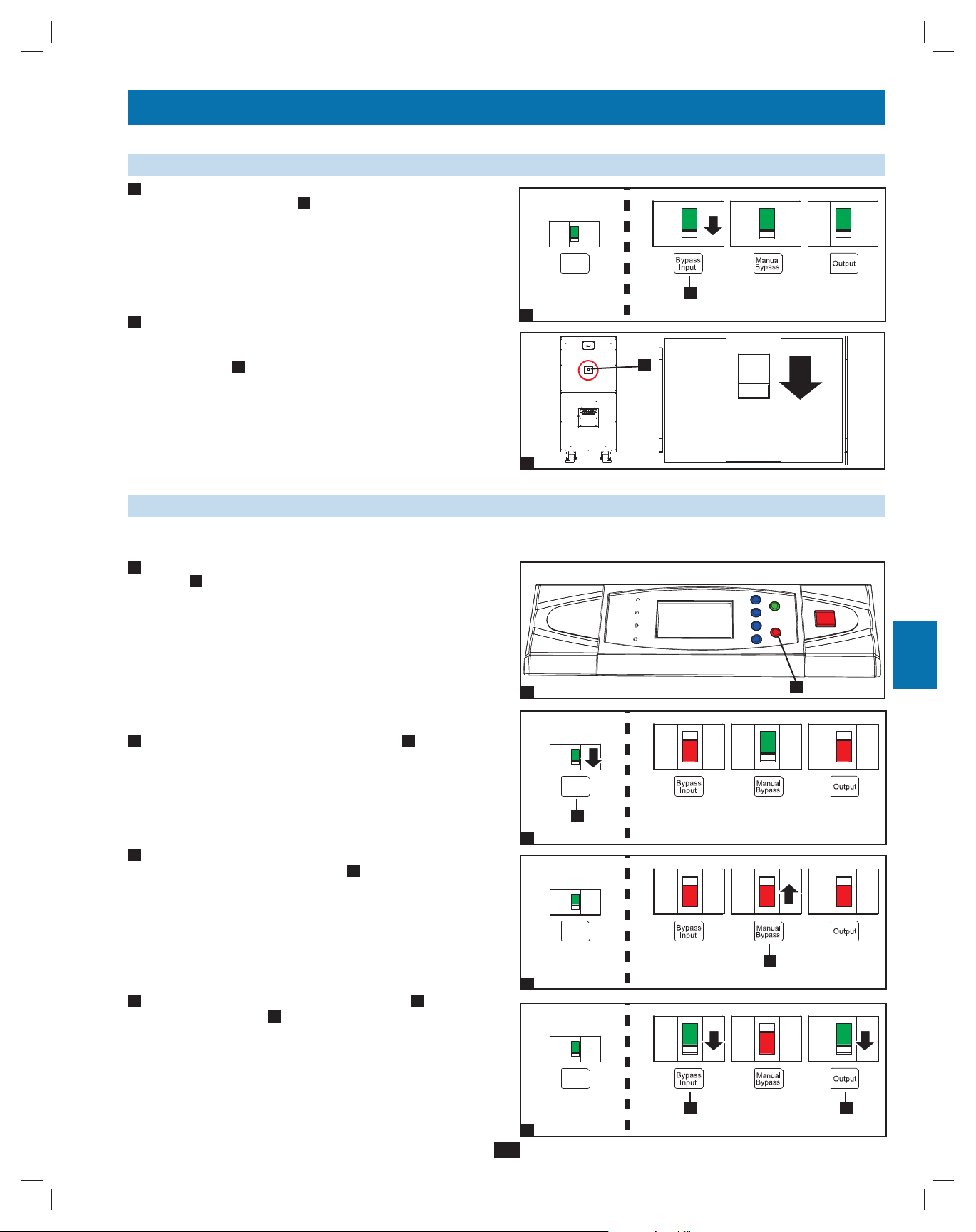
When the UPS system is in online (normal) mode, press the OFF •
1
3
button A for 3 seconds (until you hear a beep), then release the
button. The inverter will automatically switch to bypass mode and
the “BYPASS” LED will illuminate.
4
Switch on the manual bypass circuit breaker switch •
2
off the output circuit breaker switch B.
5
Section 8-6. Although connected equipment loads will be powered by the bypass power source,
A
1
A
, then switch
ON
Main
Input
ON
I
I
ON
I
OFF
O
6
8-6 Shutdown Procedure (Single UPS)
7
Front Panel
2
A B
Back Panel
Warning: The UPS system shutdown procedure will eliminate the AC power output for all loads. Before shutdown, confirm that all loads
are turned off or place the UPS system in manual bypass mode to keep loads powered by the bypass power source.
Press the OFF button •
1
8
release the button. If the UPS system is in online (normal) mode, it
will switch to bypass mode. If the UPS system is in battery backup
A
for 3 seconds (until you hear a beep), then
mode, the inverter will shut down and AC output power will be
interrupted.
9
10
11
12
1
2
Switch off the main input circuit breaker switch •
A
.
OFF
Main
Input
O
ON
I
A
Front Panel
2
3
Switch off the bypass input circuit breaker switch •
A
.
O
OFF
OFF
Back Panel
O
OFF
OFF
A
O
O
ON
I
ON
I
Main
Input
13
Front Panel
3
A
Back Panel
22
200803004 93-2793 SU80k manual 4C.indd E22200803004 93-2793 SU80k manual 4C.indd E22 6/16/2008 1:43:34 PM6/16/2008 1:43:34 PM
Page 23
8 – Start-Up, Shutdown and Bypass (continued)
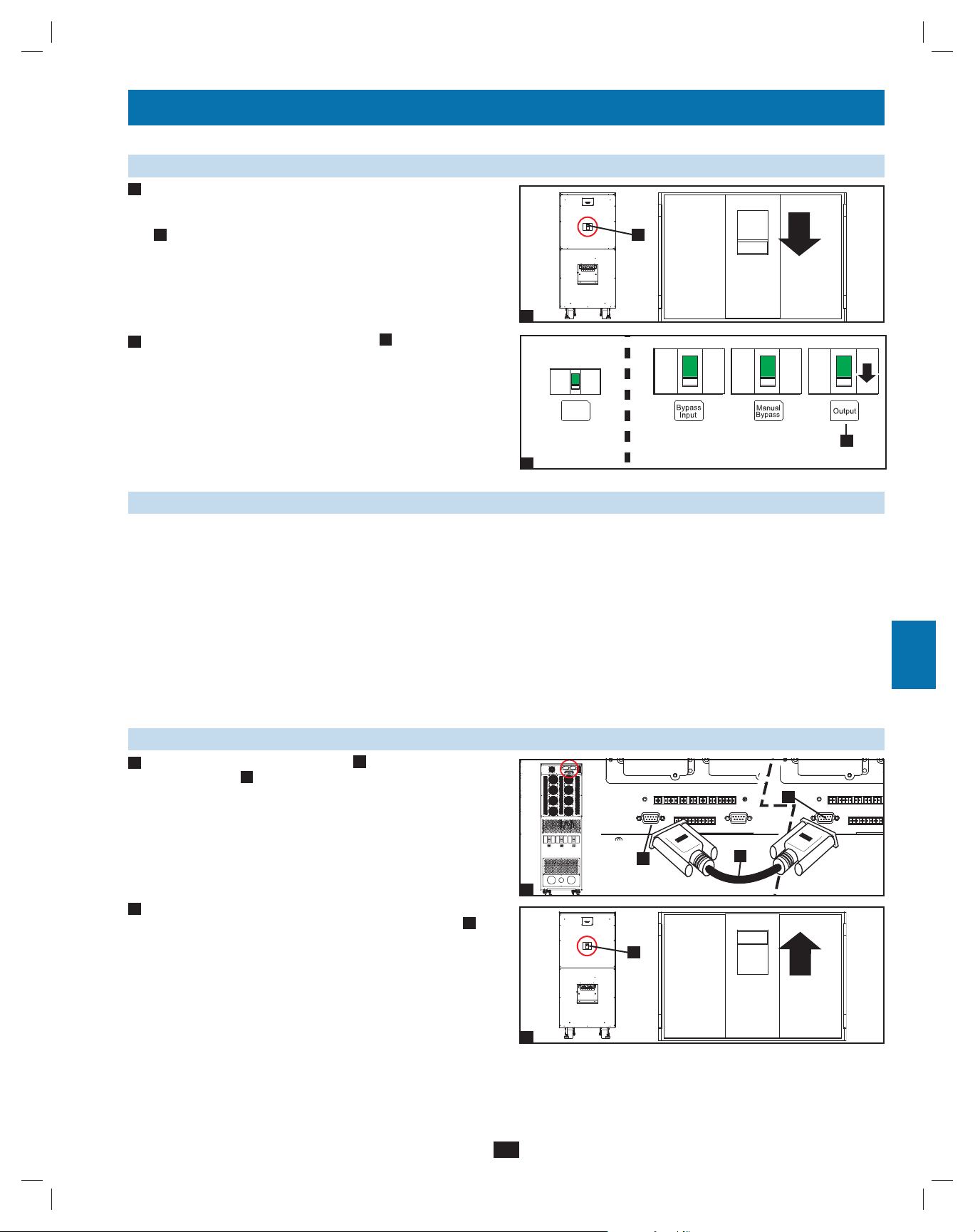
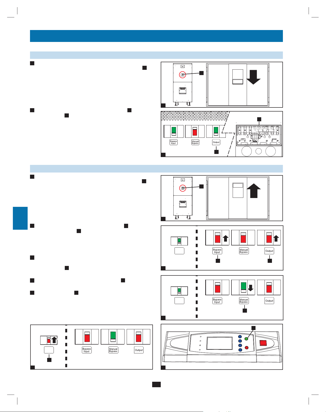
8-6 Shutdown Procedure (Single UPS) (continued)
Confirm that the UPS system is off and that all main output circuits •
4
are off. If the UPS system is connected to an external battery
cabinet, turn off the external battery cabinet circuit breaker switch
A
.
4
Switch off the output circuit breaker switch •
5
power source is normal, the UPS system is ready for start-up.
Note: If the UPS system remains off for an extended period of time, it
should be turned on periodically to allow the batteries to recharge. The
UPS system should be turned on and the batteries should be recharged
at least one uninterrupted 24-hour period every 3 months. Failure
to recharge the batteries periodically may cause irreversible battery
damage.
A
. If the AC input
Front Panel
5
OFF
Main
Input
1
2
A
3
O
O
OFF
O
OFF
Back Panel
OFF
O
A
4
5
8-7 Preliminary Checklist (Parallel UPS)
Warning: Parallel redundancy requires exactly two UPS systems (1+1 redundancy). Do not attempt to link more than two UPS systems
via parallel redundancy. The UPS systems must have the same rating and capacity for parallel redundancy installation. Attempting to link
dissimilar UPS systems will damage the UPS systems and create a serious risk of personal injury and property damage.
All circuit breaker switches should be off, including the breakers of the external battery cabinets.•
Confirm that no voltage potential exists between Neutral and Ground.•
Confirm that the input power source matches the rating (voltage, frequency and phase) of the UPS systems.•
You must use the control panel to set the parallel ID numbers of the UPS systems to be 1 and 2. See • Section 9-11 for information
about setting the parallel ID numbers.
Note: After start-up, the UPS systems will perform a brief self-test and display the results on the LCD screen. After a successful self-test, the UPS
systems will provide AC power to the connected equipment load.
8-8 Start-Up Procedure (Parallel UPS)
Connect the parallel redundancy cable •
1
redundancy port B of each UPS system.
If the UPS systems have external battery cabinets connected, •
2
switch on the external battery cabinet circuit breaker switch A of
each battery pack.
A
to the DB9 parallel
B
B
1
A
A
6
7
8
9
10
11
12
2
23
200803004 93-2793 SU80k manual 4C.indd E23200803004 93-2793 SU80k manual 4C.indd E23 6/16/2008 1:43:37 PM6/16/2008 1:43:37 PM
13
Page 24
8 – Start-Up, Shutdown and Bypass (continued)
1
8-8 Start-Up Procedure (Parallel UPS) (continued)
Switch on the bypass input circuit breaker switch •
3
2
UPS system. After a brief initialization process, the LCD screen
will show “ON AUTO BYPASS” and the “BYPASS” LED will
illuminate.
3
4
Switch on the main input circuit breaker switch •
4
system.
5
5
Press the ON button •
6
(until you hear a beep), then release the button. The inverter will
activate and synchronize with the bypass source. Press the ON
button for the other UPS system for 3 seconds (until you hear a
beep), then release the button. When the inverter of each UPS
system is operating normally, they will automatically switch from
7
auto bypass mode to online (normal) mode at the same time.
The “BYPASS” LED will darken and the “NORMAL” LED will
illuminate.
6
Check the output voltage of each UPS system. The phase deviation •
8
between each UPS system should be less than 5V. If the phase
deviation is within the acceptable range, switch on the output
circuit breaker switch A of each UPS system. Note: For more
information on checking the output voltage of each UPS system,
see Section 9-6.
A
of one of the UPS systems for 3 seconds
9
A
of each
A
of each UPS
Front Panel
3
Front Panel
4
5
Front Panel
6
OFF
Main
Input
Main
Input
Main
Input
O
O
ON
I
OFF
OFF
O
A
Back Panel
O
ON
ON
I
I
OFF
OFF
O
A
Back Panel
A
O
ON
ON
I
I
OFF
ON
I
A
Back Panel
8-9 Shutdown Procedure (Parallel UPS)
10
Warning: The UPS system shutdown procedure will eliminate the AC power output for all loads. Before shutdown, confirm that all loads
are turned off or place the UPS systems in manual bypass mode to keep loads powered by the bypass power source.
1
For the UPS system you wish to shut down, press the OFF button •
A
11
for 3 seconds (until you hear a beep), then release the button.
If the other UPS system can support the connected equipment
loads alone, the UPS system that was turned off will shut down its
inverter and its LCD screen will read “LOAD NOT POWERED”.
The other UPS system’s LCD screen will read “ONLINE MODE”.
12
If the total connected equipment load is too large to be handled
by a single UPS system, both UPS systems will shut down their
inverters and switch to bypass mode, and their LCD screens will
1
A
read “ON AUTO BYPASS”.
2
For the UPS system you wish to shut down, switch off the main •
13
200803004 93-2793 SU80k manual 4C.indd E24200803004 93-2793 SU80k manual 4C.indd E24 6/16/2008 1:43:41 PM6/16/2008 1:43:41 PM
input circuit breaker switch A, then switch off the output circuit
breaker switch B.
24
Front Panel
2
OFF
Main
Input
O
ON
I
A B
O
OFF
Back Panel
OFF
O
Page 25
8 – Start-Up, Shutdown and Bypass (continued)
8-9 Shutdown Procedure (Parallel UPS) (continued)
For the UPS system you wish to shut down, switch off the bypass •
3
input circuit breaker switch
When the UPS system is completely shut down, the LCD screen •
4
will be completely off. If the UPS systems have external battery
cabinets connected, switch off the external battery cabinet circuit
breaker switch A of each battery pack.
Note: If the UPS system remains off for an extended period of time, it
should be turned on periodically to allow the batteries to recharge. The
UPS system should be turned on and the batteries should be recharged
at least one uninterrupted 24-hour period every 3 months. Failure
to recharge the batteries periodically may cause irreversible battery
damage.
A
.
Front Panel
3
4
OFF
Main
Input
1
2
O
O
OFF
OFF
O
OFF
O
3
A
Back Panel
A
4
5
8-10 Manual Bypass Procedure (Parallel UPS)
Warning: When the UPS system is in manual bypass, the inverter shuts down. Connected equipment loads are powered by the bypass
power source and will not receive battery backup during a utility power failure.
For the first UPS system you wish to shut down, press the OFF •
1
button A for 3 seconds (until you hear a beep), then release
the button. If the other UPS system can support the connected
equipment loads alone, the UPS system that was turned off will
shut down its inverter and its LCD screen will read “LOAD NOT
POWERED”. The other UPS system’s LCD screen will read
“ONLINE MODE”. If the total connected equipment load is too
large to be handled by a single UPS system, both UPS systems
will shut down their inverters and switch to bypass mode, and their
LCD screens will read “ON AUTO BYPASS”. Repeat step 1 for
the second UPS system you wish to shut down.
2
Switch off the main input circuit breaker switch •
A
of each UPS
system.
3
Confirm that both UPS systems are shut down, then switch on the •
manual bypass circuit breaker switch A of each UPS system. The
bypass power source will power the loads and the LCD screen will
read “ON MANUAL BYPASS”.
1
Front Panel
2
OFF
Main
Input
OFF
O
ON
I
A
Back Panel
O
ON
I
OFF
ON
A
O
I
ON
I
ON
I
6
7
8
9
10
11
Main
Input
12
13
Switch off the bypass input circuit breaker switch •
4
A
circuit breaker switch B of each UPS system. The LCD screen
will turn off completely.
and the output
Front Panel
3
OFF
Main
Input
A
Back Panel
O
O
OFF
ON
I
OFF
O
A B
Front Panel
4
Back Panel
25
200803004 93-2793 SU80k manual 4C.indd E25200803004 93-2793 SU80k manual 4C.indd E25 6/16/2008 1:43:46 PM6/16/2008 1:43:46 PM
Page 26
8 – Start-Up, Shutdown and Bypass (continued)
O
OFF
O
OFF
ON
I
1
8-10 Manual Bypass Procedure (Parallel UPS) (continued)
If the UPS systems have external battery cabinets connected, •
5
2
switch off the external battery cabinet circuit breaker switch
each battery pack.
3
6
In this mode, only the output circuit breaker switch •
4
terminal block B contain hazardous voltage, allowing qualified
service personnel to perform maintenance or repair. Note:
Qualified service personnel may prefer to de-energize the UPS
systems completely, depending on local codes and the nature of the
maintenance or repair.
A
5
and the
A
of
A
5
B
6
6
8-11 Switching from Manual Bypass to Normal Mode (Parallel UPS)
If the UPS systems have external battery cabinets connected, •
1
switch on the external battery cabinet circuit breaker switch A of
each battery pack.
7
8
2
Switch on the bypass input circuit breaker switch •
circuit breaker switch B of each UPS system.
A
and the output
1
9
3
Confirm that the LCD screens of both UPS systems read “ON •
10
11
12
13
MANUAL BYPASS”, then switch off the manual bypass circuit
breaker switch A of each UPS system. The LCD screen will read
“ON AUTO BYPASS”.
Switch on the main input circuit breaker switch •
4
A
of each UPS
system.
5
Press the ON button •
A
of the first UPS systems for 3 seconds
(until you hear a beep), then release the button. Press the ON
button for the second UPS system for 3 seconds (until you hear
a beep), then release the button. When the inverter of each UPS
system is operating normally, they will switch to online (normal)
mode at the same time.
O
ON
Main
Input
ON
I
I
OFF
ON
I
Front Panel
2
Front Panel
3
OFF
Main
Input
OFF
Main
Input
O
O
Back Panel
A
A
ON
I
ON
I
A B
Back Panel
O
ON
I
OFF
A
Back Panel
A
ON
I
ON
I
A
Front Panel
4
200803004 93-2793 SU80k manual 4C.indd E26200803004 93-2793 SU80k manual 4C.indd E26 6/16/2008 1:43:50 PM6/16/2008 1:43:50 PM
Back Panel
5
26
Page 27
9 – Display and Confi guration
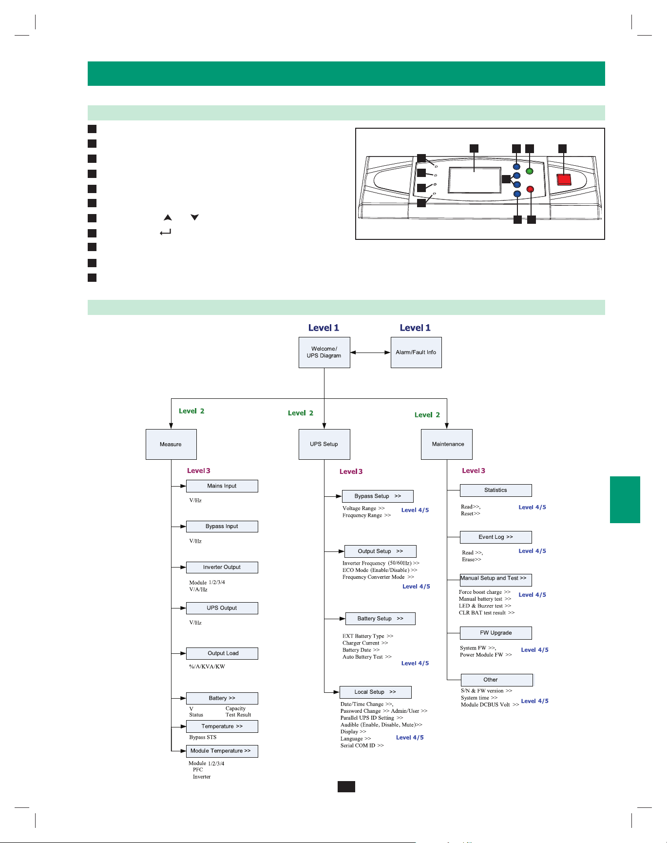
9-1 Control Panel Diagram
“NORMAL” LED•
A
“BATTERY” LED•
B
“BYPASS” LED•
C
“FAULT” LED•
D
LCD Status Screen•
E
“ESC” (Escape) Button•
F
Scroll Buttons (• and )
G
Enter Button (• )
H
I
ON Button•
OFF Button•
J
“EPO” (Emergency Power Off) Button•
K
9-2 Display Hierarchy
1
2
E
A
B
C
D
Control Panel
F
I
G
K
3
J
H
4
5
6
7
8
9
10
11
12
13
27
200803004 93-2793 SU80k manual 4C.indd E27200803004 93-2793 SU80k manual 4C.indd E27 6/16/2008 1:43:56 PM6/16/2008 1:43:56 PM
Page 28
9 – Display and Confi guration (continued)
1
9-3 Default Display
After the UPS system starts up and completes the self-test, the •
1
2
3
4
5
6
7
LCD status screen will show the default display. The default
display includes a status message and diagram that shows the
operational status of the UPS system. If an alarm event occurs, an
exclamation point will flash in the lower right corner of the LCD
status screen.
Press the scroll down button (• ) to see an event message, which
2
may include diagnostic information. Press the scroll down button
( ) again to see the next message. If no other event messages
exist, the screen will return to the default display. Note: Pressing
the “ESC” button will return to the default display.
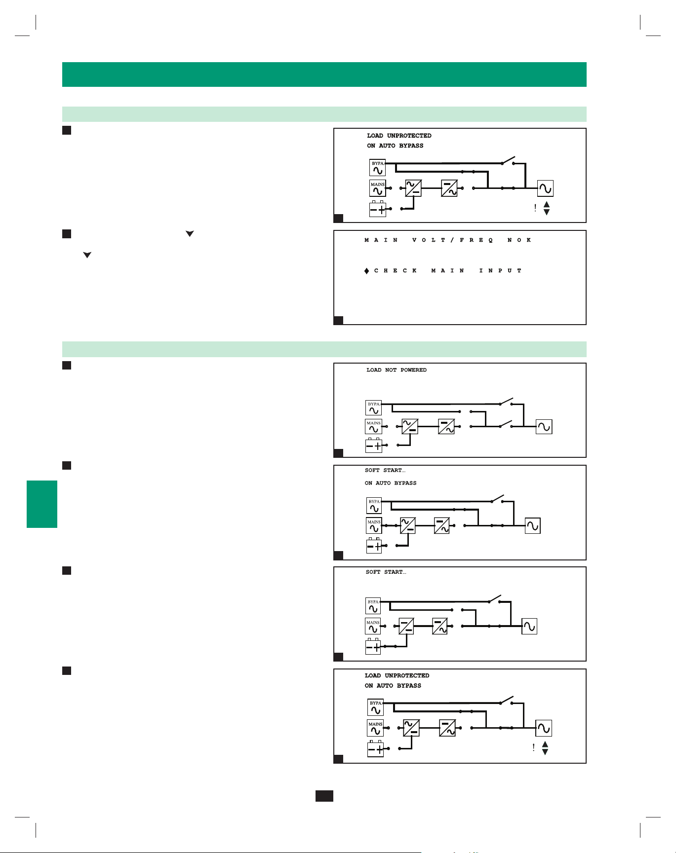
9-4 Status Messages and Diagrams
The UPS system output is off and the connected equipment loads •
1
are not powered. This condition may be due to automatic UPS
shutdown or manually switching off the output circuit breaker
switch.
1
2
10
11
12
13
8
Connected equipment loads are powered by the bypass power •
2
source at initial UPS system start-up.
1
9
2
3
The UPS system is starting up from battery power.•
3
The UPS system is in auto bypass mode. Connected equipment •
4
loads will lose power if the bypass power source fails.
4
28
200803004 93-2793 SU80k manual 4C.indd E28200803004 93-2793 SU80k manual 4C.indd E28 6/16/2008 1:43:56 PM6/16/2008 1:43:56 PM
Page 29
9 – Display and Confi guration (continued)
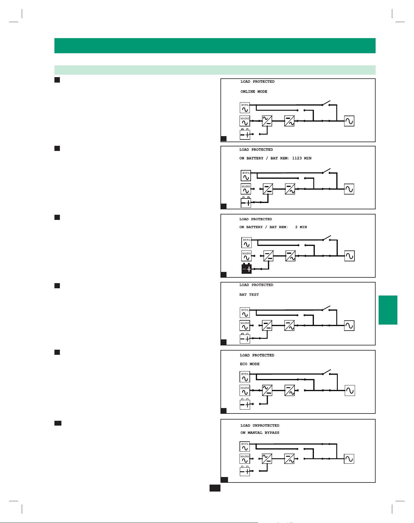
9-4 Status Messages and Diagrams (continued)
The UPS system is operating in online (normal) mode. Connected •
5
equipment loads will receive battery backup power if the mains
(utility or generator) power source fails.
The UPS system has switched to battery backup (on battery) mode. •
6
Connected equipment loads are receiving battery backup power,
and the estimated remaining runtime is shown. Note: The battery
parameters must be set correctly in order to receive accurate
runtime estimates from the UPS system when it switches to battery
backup mode. See Section 9-10 for more information.
7
The UPS system has switched to battery backup (on battery) mode. •
Connected equipment loads are still receiving AC power inverted
from battery power, but battery power is nearly depleted.
1
2
3
5
4
5
6
6
8
The UPS system is performing a battery test.•
9
The UPS system is operating in economy mode, and connected •
equipment loads are being powered by the bypass source.
7
7
8
9
8
10
11
9
12
The UPS system is in manual bypass mode in order to allow •
10
qualified service personnel to perform maintenance or repair on
the UPS system. Connected equipment loads will lose power if the
bypass power source fails.
10
29
200803004 93-2793 SU80k manual 4C.indd E29200803004 93-2793 SU80k manual 4C.indd E29 6/16/2008 1:43:56 PM6/16/2008 1:43:56 PM
13
Page 30
9 – Display and Confi guration (continued)
1
9-5 Main Menu
From the default display, press the enter button (• ) to access
1
2
3
4
5
6
the main menu. Press the scroll down button ( ) or the scroll
up button ( ) to move the cursor. Press the enter button ( ) to
select one of the available menu options.
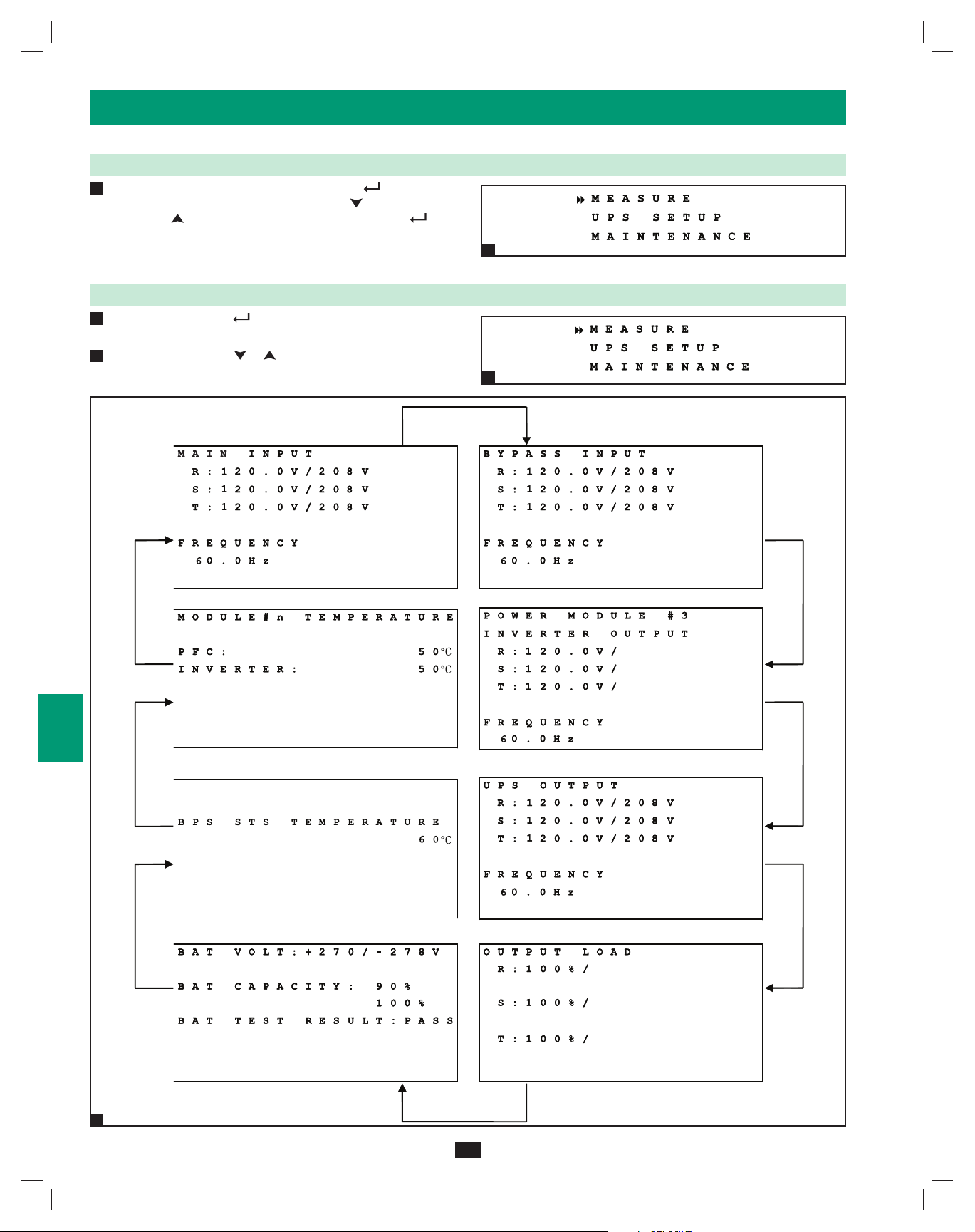
9-6 UPS System “Measure” Menu
Press the enter button (• ) to select “MEASURE” from the main
1
menu.
Use the scroll buttons (• or ) to scroll through the available data
2
screens. Press the “ESC” button to return to the previous menu.
1
1
10
11
12
13
7
8
45.0A
45.0A
45.0A
9
BAT STATUS:CHARGING
80.0KVA/64.0KW
80.0KVA/64.0KW
80.0KVA/64.0KW
74A
74A
74A
2
30
200803004 93-2793 SU80k manual 4C.indd E30200803004 93-2793 SU80k manual 4C.indd E30 6/16/2008 1:43:56 PM6/16/2008 1:43:56 PM
Page 31

9 – Display and Confi guration (continued)
9-7 UPS System Setup Menu
Press the enter button (• ) to select “UPS SETUP” from the main
1
menu.
Accessing the UPS system setup menu requires a password. From •
2
the login screen, press the enter button ( ) to select whether
to log in as an administrator or a user. Administrators can view
and change all UPS system parameters; regular users can view
all parameters, but can only change a few basic parameters. Only
qualified service personnel should log in as the administrator.
3
The password consists of 4 numerals. Press the scroll down button •
( ) or the scroll up button ( ) to select the first numeral, then
press the enter button ( ) to enter the numeral choice. After
entering the last numeral, press the enter button ( ) to confirm
the password choice. The default user password is 0000. The
default administrator password is 0000. Only qualified service
personnel should have access to the administrator password. See
Section 9-11 for instructions on changing the passwords.
1
2
1
3
4
2
5
6
After the correct password has been entered, the LCD screen will •
4
show the UPS system setup menu.
9-8 Bypass Setup Menu
Enter the UPS system setup menu as described in • Section 9-7.
1
Use the scroll buttons (
SETUP”, then press the enter button (
Use the scroll buttons (• , ) and the enter button ( ) to select
2
“VOLTAGE RANGE” or “FREQUENCY RANGE”.
, ) to move the cursor to “BYPASS
).
3
7
8
4
9
10
11
1
12
13
2
31
200803004 93-2793 SU80k manual 4C.indd E31200803004 93-2793 SU80k manual 4C.indd E31 6/16/2008 1:43:57 PM6/16/2008 1:43:57 PM
Page 32

9 – Display and Confi guration (continued)
1
9-8 Bypass Setup Menu (continued)
From the “VOLTAGE RANGE” screen, use the scroll buttons •
3
2
3
4
5
( , ) to select a bypass voltage range and press the enter button
( ) to confirm the setting.
4
From the “FREQUENCY RANGE” screen, use the scroll buttons •
( , ) to select a bypass frequency range and press the enter
button ( ) to confirm the setting.
Note: Press the “ESC” button to return to the previous menu.
3
6
9-9 Output Setup Menu
Note: The UPS system must be in bypass mode to change the output
parameters.
7
1
Enter the UPS system setup menu as described in • Section 9-7.
Use the scroll buttons ( , ) to move the cursor to “OUTPUT
SETUP”, then press the enter button ( ).
8
2
9
Use the scroll buttons (• , ) and the enter button ( ) to select
one of the menu choices.
10
3
11
From the “VOLTAGE” screen, use the scroll buttons •
( , ) to select the desired setting and press the enter button ( )
to confirm the setting.
4
1
2
12
3
13
32
200803004 93-2793 SU80k manual 4C.indd E32200803004 93-2793 SU80k manual 4C.indd E32 6/16/2008 1:43:57 PM6/16/2008 1:43:57 PM
Page 33

9 – Display and Confi guration (continued)
9-9 Output Setup Menu (continued)
4
From the “FREQUENCY” screen, use the scroll buttons (• , )
to select the desired setting and press the enter button ( ) to
confirm the setting. Note: The output frequency setting is only
used when the UPS system starts from battery or when frequency
converter mode (see step 6) is enabled.
From the “ECONOMIC MODE” screen, use the scroll buttons •
5
( , ) to select the desired setting and press the enter button ( )
to confirm the setting.
6
From the “FREQ CONVERTER MODE” screen, use the scroll •
buttons ( , ) to select the desired setting and press the enter
button ( ) to confirm the setting.
Note: Press the “ESC” button to return to the previous menu.
1
2
3
4
4
5
5
6
7
6
9-10 Battery Setup Menu
Note: The UPS system must be in bypass mode to change the battery parameters. The battery parameters must be set correctly in order to receive
accurate runtime estimates from the UPS system when it switches to battery backup mode.
1
Enter the UPS system setup menu as described in •
Use the scroll buttons (
SETUP”, then press the enter button ( ).
Use the scroll buttons (• , ) and the enter button ( ) to select
2
one of the menu choices.
, ) to move the cursor to “BATTERY
Section 9-7.
1
2
8
9
10
11
12
13
33
200803004 93-2793 SU80k manual 4C.indd E33200803004 93-2793 SU80k manual 4C.indd E33 6/16/2008 1:43:58 PM6/16/2008 1:43:58 PM
Page 34

9 – Display and Confi guration (continued)
1
9-10 Battery Setup Menu (continued)
3
From the “EXT BAT TYPE” screen, use the scroll buttons •
, ) to select the desired settings and press the enter button
2
3
4
5
(
( ) to confirm the settings. Note: Possible battery types are
26AH, 40AH, 100AH or 140AH. Possible string settings are
1, 2, 3 or 4.
4
From the “CHARGER CURRENT” screen, use the scroll buttons •
( , ) to select the desired setting and press the enter button ( )
to confirm the setting. Note: The default charger current setting is
7A.
3
6
From the “BAT DATE SETTING” screen, use the scroll buttons •
5
( , ) to select the desired settings and press the enter button
( ) to confirm the settings.
7
8
6
From the “AUTO BAT TEST” screen, use the scroll buttons •
( , ) to select the desired setting and press the enter button ( )
to confirm the setting.
9
Note: Press the “ESC” button to return to the previous menu.
10
11
4
5
6
12
13
34
200803004 93-2793 SU80k manual 4C.indd E34200803004 93-2793 SU80k manual 4C.indd E34 6/16/2008 1:43:58 PM6/16/2008 1:43:58 PM
Page 35

9 – Display and Confi guration (continued)
9-11 Local Setup Menu
Enter the UPS system setup menu as described in • Section 9-7. Use
1
the scroll buttons ( , ) to move the cursor to “LOCAL SETUP”,
then press the enter button ( ).
Use the scroll buttons (• , ) and the enter button ( ) to select
2
one of the menu choices.
3
From the “DATE/TIME CHANGE” screen, use the scroll buttons •
( , ) to select the desired settings and press the enter button
( ) to confirm the settings. Note: Changing this setting does not
require an administrator login – a user login is sufficient.
1
2
3
1
4
5
2
6
4
From the “PASSWORD CHANGE” screen, use the scroll buttons •
( , ) and the enter button ( ) to select the desired menu
choice. Use the scroll buttons ( , ) to select the desired settings
and press the enter button ( ) to confirm the settings. Note:
The administrator password should be used by qualified service
personnel only.
From the “PARALLEL ID” screen, use the scroll buttons (• , )
5
to select the desired settings and press the enter button (
to confirm the settings. Note: If two UPS systems are used in a
parallel redundancy configuration, the parallel ID numbers of the
UPS systems must be 1 and 2.
7
3
8
9
4
10
11
4b
)
12
13
5
35
200803004 93-2793 SU80k manual 4C.indd E35200803004 93-2793 SU80k manual 4C.indd E35 6/16/2008 1:43:58 PM6/16/2008 1:43:58 PM
Page 36

9 – Display and Confi guration (continued)
1
9-11 Local Setup Menu (continued)
From the “AUDIBLE” screen, use the scroll buttons (• , ) to
6
2
3
4
5
6
select the desired settings for the audible alarm and press the enter
button ( ) to confirm the setting.
From the “DISPLAY” screen, use the scroll buttons (• , ) to
7
select the desired LCD contrast setting and press the enter button
( ) to confirm the setting. Note: Changing this setting does not
require an administrator login – a user login is sufficient.
From the “LANGUAGE” screen, use the scroll buttons (• , )
8
to select the desired setting and press the enter button ( ) to
confirm the setting. Note: Changing this setting does not require
an administrator login – a user login is sufficient.
6
7
7
8
9
From the “SERIAL COM ID” screen, use the scroll buttons •
( , ) to select the desired serial port ID and press the enter
button ( ) to confirm the setting. Note: This setting does not
apply to standard RS-232 connections. It only applies for RS-485/
9
RS-422 communications.
Note: Press the “ESC” button to return to the previous menu.
10
9-12 Maintenance Menu
Press the enter button (• ) to select “MAINTENANCE” from
1
11
12
the main menu. Follow the login procedure described in step 2 and
step 3 of Section 9-7.
2
After the correct password has been entered, the LCD screen will •
show the maintenance menu. Use the scroll buttons ( , ) and the
enter button (
) to select a menu choice.
8
9
1
13
2
36
200803004 93-2793 SU80k manual 4C.indd E36200803004 93-2793 SU80k manual 4C.indd E36 6/16/2008 1:43:58 PM6/16/2008 1:43:58 PM
Page 37

9 – Display and Confi guration (continued)
9-13 Statistics Menu
Enter the maintenance menu as described in • Section 9-12. Use the
1
scroll buttons ( , ) to move the cursor to “STATISTIC”, then
press the enter button ( ).
If you wish to view statistical data, use the scroll buttons (• , )
2
and the enter button ( ) to select “READ” from the menu.
3
Available statistical data includes the total operating time, the •
number of battery events and the number of bypass events.
1
2
3
1
4
5
2
6
4
If you wish to reset the statistical data, use the scroll buttons •
( , ) and the enter button ( ) to select “RESET” from the
menu.
5
You must enter the administrator password to confirm the reset •
operation.
Note: Press the “ESC” button to return to the previous menu.
7
3
8
9
4
10
11
5
12
13
37
200803004 93-2793 SU80k manual 4C.indd E37200803004 93-2793 SU80k manual 4C.indd E37 6/16/2008 1:43:59 PM6/16/2008 1:43:59 PM
Page 38

9 – Display and Confi guration (continued)
1
9-14 Event Log Menu
Enter the maintenance menu as described in • Section 9-12. Use the
1
2
3
4
5
6
scroll buttons ( , ) to move the cursor to “EVENT LOG”, then
press the enter button ( ).
2
If you wish to view the event log, use the scroll buttons (• , ) and
the enter button ( ) to select “READ” from the event log menu.
Use the scroll buttons (• , ) to scroll through the event log data.
3
Press the “ESC” button to return to the previous menu.
1
2
7
8
If you wish to erase the event log, use the scroll buttons (• , ) and
4
the enter button ( ) to select “ERASE” from the event log menu.
9
10
5
You must enter the administrator password to confirm the reset •
operation.
Note: Press the “ESC” button to return to the previous menu.
11
12
3
4
5
13
38
200803004 93-2793 SU80k manual 4C.indd E38200803004 93-2793 SU80k manual 4C.indd E38 6/16/2008 1:44:00 PM6/16/2008 1:44:00 PM
Page 39

9 – Display and Confi guration (continued)
9-15 Manual Setup & Test Menu
Enter the maintenance menu as described in • Section 9-12. Use the
1
scroll buttons (
TEST”, then press the enter button (
2
Use the scroll buttons (•
menu choice.
3
Select “FORCE BOOST CHARGE” to boost the battery charge •
rate. You must enter the administrator password to confirm the
operation. Warning: Boosting the battery charge rate for an
extended period may damage the battery system.
, ) to move the cursor to “MANUAL SETUP &
).
, ) and the enter button ( ) to select a
1
2
3
1
4
5
2
6
4
Select “MANUAL BATTERY TEST” to initiate a battery test. You •
must enter the administrator password to confirm the operation.
5
Select “BUZZER AND LED TEST” to initiate test of the control •
panel LEDs and audible alarm. You must enter the administrator
password to confirm the operation.
Select “CLR BAT TEST RESULT” to remove the battery test •
6
results from the “MEASURE” menu. (See
information.)
Note: Press the “ESC” button to return to the previous menu.
Section 9-6 for more
7
3
8
9
4
10
11
5
12
13
6
39
200803004 93-2793 SU80k manual 4C.indd E39200803004 93-2793 SU80k manual 4C.indd E39 6/16/2008 1:44:00 PM6/16/2008 1:44:00 PM
Page 40

9 – Display and Confi guration (continued)
1
9-16 Firmware Upgrade Menu
Warning: The firmware should be upgraded by qualified service personnel only. Use only firmware that has been approved by Tripp Lite.
Failure to comply will void the warranty.
2
1
Enter the maintenance menu as described in •
the scroll buttons ( , ) to move the cursor to “FIRMWARE
UPGRADE”, then press the enter button ( ).
3
Section 9-12. Use
4
Use the scroll buttons (• , ) and the enter button ( ) to
2
select one of the menu choices. You must enter the administrator
5
password to confirm the operation.
Note: Press the “ESC” button to return to the previous menu.
6
9-17 Other Menu Choices
7
1
Enter the maintenance menu as described in • Section 9-12. Use the
scroll buttons ( , ) to move the cursor to “OTHERS”, then press
the enter button ( ).
8
9
2
Use the scroll buttons (• , ) and the enter button ( ) to select
a menu choice. “SN & FW VERSION” shows the serial number
and firmware version of the UPS system. “SYSTEM TIME” shows
the UPS system’s current date and time. “MODULE DC BUS
10
VOLT” shows the current voltage of the DC bus. Qualified service
personnel may wish to view this information when performing
maintenance or repair on the UPS system.
Note: Press the “ESC” button to return to the previous menu.
11
1
2
1
2
12
13
40
200803004 93-2793 SU80k manual 4C.indd E40200803004 93-2793 SU80k manual 4C.indd E40 6/16/2008 1:44:00 PM6/16/2008 1:44:00 PM
Page 41

10 – Communications
Note: The communications connections described in this section are optional. The UPS system will function properly without these connections.
1
10-1 Communications Interfaces
Parallel
Redundancy Port
Output Dry
Contact Interface
2
SNMPWEBCARD Slot
3
4
5
Input Dry Contact
Interface
6
RS-232
Serial Port
7
10-2 SNMPWEBCARD Slot
Remove the cover panel to install a Tripp Lite SNMPWEBCARD accessory. The SNMPWEBCARD accessory provides an Ethernet interface for
the UPS system and enables remote monitoring and control via SNMP, Web browser or telnet. Call (773) 869-1234 for more information about
ordering the SNMPWEBCARD accessory.
10-3 Input Dry Contact Interface
The input dry contact interface receives contact-closure signals that allow the UPS system to receive commands and monitor external battery
conditions:
P1—Remote Emergency Power Off (EPO)
P2—Auxiliary Dry Contact Inputs (2 sets)
P3—External Battery Cabinet Temperature 1
P4—External Battery Cabinet Temperature 2
P5—External Battery Cabinet Temperature 3
P6—External Battery Cabinet Temperature 4
P7—External Battery Status
8
9
10
11
12
13
41
200803004 93-2793 SU80k manual 4C.indd E41200803004 93-2793 SU80k manual 4C.indd E41 6/16/2008 1:44:00 PM6/16/2008 1:44:00 PM
Page 42
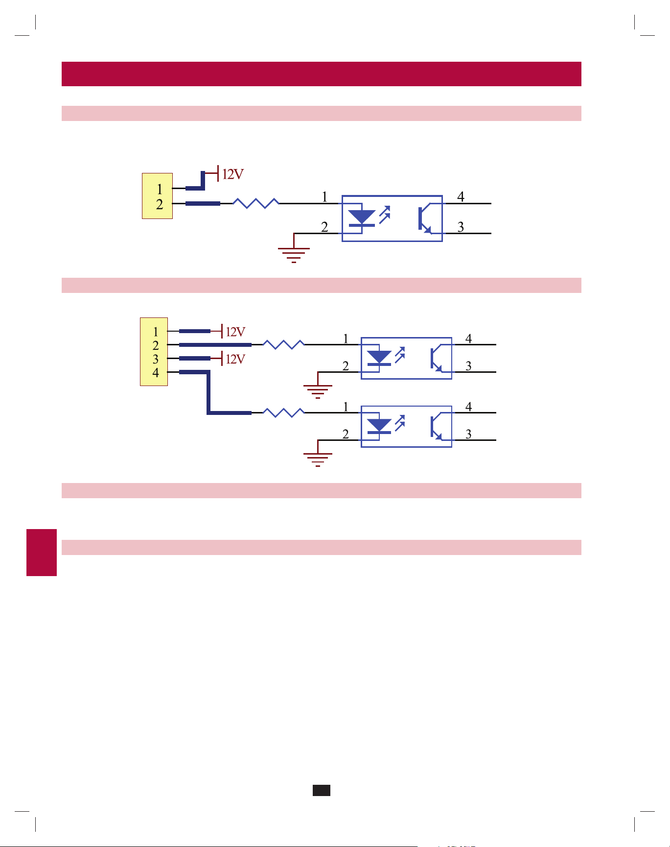
10 – Communications (continued)
1
10-4 Remote Emergency Power Off (EPO) Circuit Diagram
The Remote Emergency Power Off (EPO) input connection (P1) allows you to connect the UPS system to your facility’s EPO circuit. Connecting
the UPS system to the EPO circuit enables remote emergency shutdown of the UPS system’s output. Connect EPO input to a user-supplied remote
2
switch, following the circuit diagram below. This contact is normally open.
3
P1
4
10-5 Auxiliary Dry Contact Input Circuit Diagram
5
The auxiliary dry contact input connections (P2) allow the UPS system to receive external signals. These contacts are normally open.
6
P2
7
8
10-6 External Battery Cabinet Temperature Inputs
9
The external battery cabinet temperature input connections (P3, P4, P5, P6) allow the UPS system to receive signals from an optional accessory
that monitors the temperature of external battery cabinets. Call (773) 869-1234 for more information.
10-7 External Battery Status Input
10
The external battery cabinet status input connection (P7) allows the UPS system to receive external battery cabinet status signals through an
optional cable. Pin 1 = +12V; Pin 2 = detection cable connected; Pin 3 = battery cabinet breaker status (signal active= breaker on; signal inactive =
off); Pin 4 = reserved; Pin 5 = reference voltage. Call (773) 869-1234 for more information.
11
12
13
42
200803004 93-2793 SU80k manual 4C.indd E42200803004 93-2793 SU80k manual 4C.indd E42 6/16/2008 1:44:01 PM6/16/2008 1:44:01 PM
Page 43

10 – Communications (continued)
10-8 Output Dry Contact Interface Detail
The UPS system has six dry contact output connections. These contacts can be normally open or normally closed.
Default Messages
Contact Message Description
Pin 1-2 Load on inverter The UPS system is working normally.
Pin 3-4 Load on auto bypass The UPS system is in bypass mode.
Pin 5-6 Mains input failure with load on inverter Utility power is absent (blackout) or abnormal. The UPS system is in battery backup mode.
Pin 7-8 Battery low The UPS system is in battery backup mode, and battery voltage is lower than 220V.
Pin 9-10 Bypass input abnormal The bypass input is abnormal (frequency / phase).
Pin 11-12 Battery test failure The battery voltage is lower than the reference value.
Optional Messages
Message Description
Internal communication failure Communication with one of the internal components is not normal.
External parallel communication failure In a parallel redundancy installation, the parallel communication is not normal.
Output overload warning/shutdown The load exceeds the capacity of the UPS system.
Power module fault shutdown The UPS system has shut down due to an internal power module failure.
Power module warning An internal power module has an error, but the UPS system can still function normally.
EPO activated The UPS system’s output is disabled by the emergency power off (EPO) function.
Load on manual bypass The UPS system is in manual bypass mode.
Battery cabinet over temperature warning/shutdown The temperature of the external battery cabinet is too high.
Output voltage abnormal The UPS system’s output voltage is too high or too low.
Battery need replace According to the data in the “BAT DATE SETTING”, the UPS system is overdue for battery
replacement. (See Section 9-10 for more information.)
Bypass over temperature warning/shutdown The temperature of the bypass “static transfer switch” is too high.
Battery ground fault The battery has a grounding error.
Bypass static switch fault The bypass “static transfer switch” is abnormal.
Note: If you require optional messages to be enabled, contact Tripp Lite.
1
2
3
4
5
6
7
8
9
10
11
12
13
43
200803004 93-2793 SU80k manual 4C.indd E43200803004 93-2793 SU80k manual 4C.indd E43 6/16/2008 1:44:01 PM6/16/2008 1:44:01 PM
Page 44

10 – Communications (continued)
1
10-9 Output Dry Contact Circuit Diagram
The UPS system has six dry contact output connections. These contacts can be normally open or normally closed.
2
3
4
5
6
OUTPUT
DRY
7
CONTACT
8
9
10
11
12
13
44
200803004 93-2793 SU80k manual 4C.indd E44200803004 93-2793 SU80k manual 4C.indd E44 6/16/2008 1:44:01 PM6/16/2008 1:44:01 PM
Page 45

10 – Communications (continued)
10-10 RS-232 Serial Port Circuit Diagram
The RS-232 DB9 serial port connects the UPS system to a workstation
or server (cable included). By communicating with the UPS system
through this port, Tripp Lite’s PowerAlert UPS management software
(included) can monitor and control the UPS system. PowerAlert also
serves as an SNMP proxy allowing the UPS system to appear as an
SNMP-manageable device on the network.
RS-232 signals and operations include: load level, battery status, battery
level, operation mode, AC input voltage, AC output voltage, AC input
frequency, internal temperature, set shut-down delay time, enable/
disable alarm and remote shutdown.
Hardware
Baud Rate: 2400 BPS
Data Length: 8 bits
Stop Bit: 1 bit
Parity: NONE
Pin Assignment
Pin 2: TXD (Transmit Data)
Pin 3: RXD (Receive Data)
Pin 5: GND (Signal Ground)
10-11 Parallel Redundancy Port
The parallel redundancy port allows the UPS system to be connected to another UPS system of identical type and capacity for use in a parallel
redundancy (1+1) configuration for increased capacity or increased fault-tolerance. Warning: Use only the parallel redundancy cable that is
included with the UPS system. Attempting to use an incompatible cable may damage the UPS systems and create a serious risk of personal
injury and property damage.
1
2
3
4
5
6
7
8
9
10
11
12
13
45
200803004 93-2793 SU80k manual 4C.indd E45200803004 93-2793 SU80k manual 4C.indd E45 6/16/2008 1:44:01 PM6/16/2008 1:44:01 PM
Page 46

11 – Specifi cations
1
11-1 UPS System Technical Specifi cations
2
Model (Capacity) SU80K (80kVA/64kW)
Input Input Voltage 120/208V AC, 3Ø, 4-wire + ground, wye
Voltage Regulation -25% ~ +20%
Harmonic Distortion < 5% (Full Load)
3
PFC (Full Load) > 0.99
Frequency 50 / 60 Hz
Frequency Tolerance 45 ~ 65 Hz
Output Input Voltage 120/208V AC, 3Ø, 4-wire + ground, wye
4
Output Frequency 50 / 60 Hz
Total Harmonic (Linear Load) ≤3%
Voltage Regulation Static ±1%
Dynamic ±7% (10% ~ 90% Linear Load)
5
Frequency Regulation Interior Oscillator ±0.05 Hz
Synchronized ±5%
Overload ≤125% : 10 minutes; ≤150% : 1 minute
Audible Warning Battery Backup Intermittent
6
UPS Abnormal Continuous
Display LED UPS Status: Normal • Bypass • Backup • Fault
LCD Input/Output • Bypass • Inverter • Frequency • Loading • Battery Voltage
UPS abnormal messages with intelligent self-diagnosis.
7
Interface Standard RS-232, Dry Contact
Optional SNMPWEBCARD
Others Parallel Redundancy Yes (1+1 for 2 UPS systems of the same type and capacity only.)
EPO Standard (Local and Remote)
8
SRAM Event Log 500 Records
Parameter Configuration Yes
Hot Standby Installation Optional
Battery Temperature Compensation Optional
Battery Cold-Start Standard
9
Overall Efficiency Normal 92%
ECO 96%
Transfer Time 0 ms
Temperature 32° F ~ 104° F (0° C ~ 40° C)
10
Humidity (non-condensing) 90%
Noise (1 m) 70 dBA
Dimensions (Power Module) Width 520 mm
Depth 1026 mm
11
Height 1696 mm
Weight (Power Module) 655 kg
12
11-2 UPS System Floor Loading Table 11-3 Battery Pack Floor Loading Table
Model SU80K
Weight 655 kg
Floor Loading 1228 kg/m
13
200803004 93-2793 SU80k manual 4C.indd E46200803004 93-2793 SU80k manual 4C.indd E46 6/16/2008 1:44:01 PM6/16/2008 1:44:01 PM
2
BP480V26B BP480V40C
(40 12V batteries; (40 12V batteries;
Model 26AH each) 40AH each)
Weight 470 kg 700 kg
Floor Loading 1064 kg/m2 1575 kg/m
46
2
Page 47

12 – Storage and Service
Storage
The UPS system must be stored in a clean, secure environment with a temperature less than 40° C (104° F) and a relative humidity less than
90% (non-condensing). Store the UPS system in its original shipping container if possible. If installation occurs more than 6 months after
you receive the UPS system, recharge the batteries for at least 24 hours prior to use. Do not rely on the UPS system to provide backup power
to connected equipment until the batteries are fully charged. Note: If the UPS system remains off for an extended period of time, it should be
turned on periodically to allow the batteries to recharge. The UPS system should be turned on and the batteries should be recharged at least one
uninterrupted 24-hour period every 3 months. Failure to recharge the batteries periodically may cause irreversible battery damage.
Service
The UPS system is covered by the limited warranty described in this manual. Site survey service programs, start-up service programs, preventative
maintenance service programs and on-site warranty options (2, 3 or 4 years) are also available. For more information, call Tripp Lite Customer
Service at (773) 869-1234.
1
2
3
4
13 – Warranty and Warranty Registration
Limited Warranty
Seller warrants this product, if used in accordance with all applicable instructions, to be free from original defects in material and workmanship for a period of 2 years (except U.S., Canada and Mexico:
1 year) from the date of initial purchase. If the product should prove defective in material or workmanship within that period, Seller will repair or replace the product, in its sole discretion. Service under
this Warranty includes parts and Tripp Lite service center labor. On-site service plans are available from Tripp Lite through authorized service partners (in most areas). Contact Tripp Lite Customer
Service at (773) 869-1234 for details. International customers should contact Tripp Lite support at intlservice@tripplite.com.
THIS WARRANTY DOES NOT APPLY TO NORMAL WEAR OR TO DAMAGE RESULTING FROM ACCIDENT, MISUSE, ABUSE OR NEGLECT. SELLER MAKES NO EXPRESS WARRANTIES
OTHER THAN THE WARRANTY EXPRESSLY SET FORTH HEREIN. EXCEPT TO THE EXTENT PROHIBITED BY APPLICABLE LAW, ALL IMPLIED WARRANTIES, INCLUDING ALL WARRANTIES
OF MERCHANTABILITY OR FITNESS, ARE LIMITED IN DURATION TO THE WARRANTY PERIOD SET FORTH ABOVE; AND THIS WARRANTY EXPRESSLY EXCLUDES ALL INCIDENTAL AND
CONSEQUENTIAL DAMAGES. (Some states do not allow limitations on how long an implied warranty lasts, and some states do not allow the exclusion or limitation of incidental or consequential
damages, so the above limitations or exclusions may not apply to you. This Warranty gives you specific legal rights, and you may have other rights which vary from jurisdiction to jurisdiction).
Tripp Lite; 1111 W. 35th Street; Chicago IL 60609; USA
WARNING: The individual user should take care to determine prior to use whether this device is suitable, adequate or safe for the use intended. Since individual applications are subject to great
variation, the manufacturer makes no representation or warranty as to the suitability or fitness of these devices for any specific application.
Warranty Registration
Visit www.tripplite.com/warranty today to register the warranty for your new Tripp Lite product. You’ll be automatically entered into a drawing for a chance to win a FREE Tripp Lite product!*
* No purchase necessary. Void where prohibited. Some restrictions apply. See website for details.
Regulatory Compliance Identification Numbers
For the purpose of regulatory compliance certifications and identification, your Tripp Lite product has been assigned a unique series number. The series number can be found on the product nameplate
label, along with all required approval markings and information. When requesting compliance information for this product, always refer to the series number. The series number should not be confused
with the marking name or model number of the product.
FCC Class A Notice
This device complies with part 15 of the FCC Rules. Operation is subject to the following two conditions: (1) This device may not cause
harmful interference, and (2) this device must accept any interference received, including interference that may cause undesired operation.
Note: This equipment has been tested and found to comply with the limits for a Class A digital device, pursuant to part 15 of the FCC Rules.
These limits are designed to provide reasonable protection against harmful interference when the equipment is operated in a commercial
environment. This equipment generates, uses, and can radiate radio frequency energy and, if not installed and used in accordance with the
instruction manual, may cause harmful interference to radio communications. Operation of this equipment in a residential area is likely to
cause harmful interference in which case the user will be required to correct the interference at his own expense. The user must use shielded
cables and connectors with this equipment. Any changes or modifications to this equipment not expressly approved by Tripp Lite could void
the user’s authority to operate this equipment.
Tripp Lite has a policy of continuous improvement. Specifications are subject to change without notice.
Made in China.
Note on Labeling
These symbols are used on the label:
V~ AC Voltage
V DC Voltage
O Phase
Ground
5
6
7
8
9
10
11
12
13
47
200803004 93-2793 SU80k manual 4C.indd E47200803004 93-2793 SU80k manual 4C.indd E47 6/16/2008 1:44:01 PM6/16/2008 1:44:01 PM
Page 48

1
PROTEJA SU
¡
INVERSIÓN!
2
Las formas de arranque completas y
Tripp Lite para poder activar su garantía.
fi rmadas DEBEN ser enviadas y aprobadas por
Sistemas UPS SmartOnline™ Trifásicos
3
4
5
6
Manual del Propietario
Modelo: SU80K
Entrada/Salida: 120/208V CA, 50/60 Hz, 3Ø, 4 hilos + tierra, wye
No es apropiado para aplicaciones móviles.
10
11
12
7
8
9
13
1111 W. 35th Street, Chicago, IL 60609 USA
+1.773.869.1234 • www.tripplite.com
Derechos de Autor © 2008 Tripp Lite. Todas la marcas registradas son totalmente propiedad de sus respectivos dueños.
200803004 93-2793 SU80k manual 4C.indd S48200803004 93-2793 SU80k manual 4C.indd S48 6/16/2008 1:44:01 PM6/16/2008 1:44:01 PM
48
Page 49

Contenido
1
1 Introducción 50
2 Instrucciones de Seguridad Importantes 51
3 Características y Funciones 53
del Panel de Control
4 Características y Funciones 54
del Panel Frontal y Trasero
5 Instalación del Gabinete 56
5-1 Preparación 56
5-2 Desempaque 56
5-3 Colocación 57
6 Cableado 58
6-1 Advertencias Sobre el Cableado 58
6-2 Preparación del Cableado 58
6-3 Diagrama del Bloque de Terminal del Sistema UPS 59
6-4 Diagramas del Cableado del Gabinete de Baterías Externas 59
6-5 Información Eléctrica y Cables 60
6-6 Cableado del Gabinete de Baterías Externas 61
6-7 Cableado de Entrada/Salida CA (Un solo UPS) 62
6-8 Cableado de Entrada/Salida CA (UPS en Paralelo –Una Entrada) 63
7 Modos de Operación 64
7-1 Modo En Línea (Normal) (Un solo UPS) 64
7-2 Modo en Respaldo (Un solo UPS) 64
7-3 Modo en Derivación Automática (Un solo UPS) 64
7-4 Modo en Derivación Manual (Un solo UPS) 64
7-5 Modo En Línea (UPS en Paralelo) 65
7-6 Modo en Respaldo (UPS en Paralelo) 65
7-7 Modo en Derivación Automática (UPS en Paralelo) 65
7-8 Modo en Derivación Manual (UPS en Paralelo) 66
8 Arranque, Apagado y Derivación 67
8-1 Diagramas del Panel de Control e Interruptor de Circuitos 67
8-2 Lista de Control Preliminar (Un solo UPS) 67
8-3 Procedimiento de Arranque Normal (Un solo UPS) 67
8-4 Procedimiento de Arranque con la Batería (Un solo UPS) 68
8-5 Procedimiento de Derivación Manual (Un solo UPS) 69
8-6 Procedimiento de Apagado (Un solo UPS) 69
8-7 Revisión Preliminar (UPS en Paralelo) 70
8-8 Procedimiento de Arranque (UPS en Paralelo) 70
8-9 Procedimiento de Apagado (UPS en Paralelo) 71
8-10 Procedimiento de Derivación Manual (UPS en Paralelo) 72
8-11 Cambiando de Derivación Manual a Normal (UPS en Paralelo) 73
9 Pantalla y Confi guración 74
9-1 Diagrama del Panel de Control 74
9-2 Jerarquía de Despliegue 74
9-3 Pantalla Predeterminada 75
9-4 Mensajes de Estado y Diagramas 75
9-5 Menú Principal 77
9-6 Menú de Medidas del Sistema UPS 77
9-7 Menú de Instalación del Sistema UPS 78
9-8 Menú de Instalación de la Derivación 78
9-9 Menú de Instalación de la Salida 79
9-10 Menú de Instalación de la Batería 80
9-11 Menú de Instalación Local 82
9-12 Menú de Mantenimiento 83
9-13 Menú de Estadísticas 84
9-14 Menú de Registro de Eventos 85
9-15 Menú de Instalación Manual y Prueba 86
9-16 Menú para Actualización del Firmware 87
9-17 Menú para Otras Selecciones 87
10 Comunicaciones 88
10-1 Interfaces de Comunicaciones 88
10-2 Ranura SNMPWEBCARD 88
10-3 Interfaz de Entrada de Contacto Seco 88
10-4 Diagrama de Circuito de Apagado de Emergencia Remoto (EPO) 89
10-5 Diagrama de Circuito de Entrada Auxiliar de Contacto Seco 89
10-6 Entradas de Temperatura del Gabinete Baterías Externas 89
10-7 Entrada del Estado de la Batería Externa 89
10-8 Detalle de la Interfaz de Salida de Contacto Seco 90
10-9 Diagrama de Circuito de Salida de Contacto Seco 91
10-10 Diagrama de Circuito del Puerto Serial RS-232 92
10-11 Puerto Paralelo Redundante 92
11 Especifi caciones 93
11-1 Especifi caciones Técnicas del Sistema UPS 93
11-2 Tabla de Carga al Piso del Sistema UPS 93
11-3 Tabla de Carga al Piso del Módulo de Baterías 93
12 Almaceneaje y Servicio 94
13 Garantía 94
English 1
Français 95
2
3
4
5
6
7
8
9
10
11
12
13
49
200803004 93-2793 SU80k manual 4C.indd S49200803004 93-2793 SU80k manual 4C.indd S49 6/16/2008 1:44:02 PM6/16/2008 1:44:02 PM
Page 50

1 – Introducción
1
Los Sistemas UPS SmartOnline Trifásicos de Tripp Lite son ideales para respaldar y proteger centros de datos, telecomunicaciones (VoIP), redes,
instalaciones industriales sistemas de seguridad y emergencias y mucho más.
2
Características Avanzadas:
Doble conversión genuinamente en línea con tecnología en el inversor IGBT superior•
Corriente de entrada baja de Tasa de Distorsión Armónica (THD) permite la adecuación del tamaño del generador 1:1 para máxima eficiencia y •
ahorro en costos
3
Redundancia Interna N+1 del módulo de potencia•
Capacidad de redundancia paralela (1+1) incorporada para capacidad incrementada o tolerancia a fallas•
Hasta 80kVA de capacidad en una compacta base; hasta 160kVA en configuración de redundancia paralela (1+1)•
Factor de potencia de alta entrada y alta eficiencia con baja pérdida termal y bajo ruido•
4
Diseño simplificado, fácil de reparar, larga vida, sistema de alta disponibilidad•
Energía auxiliar redundante y circuitos de control•
Todos los modelos soportan gabinetes para baterías externas para tiempo de respaldo extendido•
5
Pantalla LCD de alta resolución simplifica la operación y entrega información operacional detallada incluyendo diagramas de bloque del sistema•
6
10
11
12
7
8
9
13
50
200803004 93-2793 SU80k manual 4C.indd S50200803004 93-2793 SU80k manual 4C.indd S50 6/16/2008 1:44:02 PM6/16/2008 1:44:02 PM
Page 51

2 – Instrucciones de Seguridad Importantes
CONSERVE ESTAS INSTRUCCIONES
Todas las secciones de este manual contiene instrucciones y advertencias que deberán ser seguidas durante la instalación y operación de los
sistemas UPS descritos en este manual. Lea cuidadosamente todas las instrucciones antes de intentar mover, instalar u operar los Sistemas
UPS descritos en este manual. El fallar en adherirse a estas instrucciones invalida la garantía y causa daños a la propiedad y/o lesiones
personales.
1
2
Advertencias Sobre la Ubicación del UPS
Instale el sistema UPS en un ambiente controlado al interior, lejos del exceso de humedad, temperaturas extremas, líquidos y gases inflamables, •
conductores contaminantes, polvo y luz solar directa.
Instale el sistema UPS en un área nivelada, estructuralmente sólida.•
El sistema UPS es extremadamente pesado. Extreme las precauciones cuando mueva o levante la unidad.•
Opere el UPS únicamente a temperaturas en el interior entre 0º C y 40º C (32º F y 104º F). Para mejores resultados, mantenga la temperatura en •
el interior entre 17° C y 29° C (62° F y 84° F).
Deje un espacio adecuado alrededor de todos los lados del UPS para una ventilación apropiada. No Obstruya, cubra o inserte objetos en las •
aberturas de de ventilación externa del gabinete.
No coloque ningún objeto sobre la unidad, especialmente los que contengan líquidos.•
No monte la unidad con el panel delantero o trasera hacia abajo (en ningún ángulo). Montándolo de esta manera inhibirá seriamente el •
enfriamiento interno de la unidad, causando finalmente daño al equipo que no está cubierto por la garantía.
No instale el UPS cerca de medios de almacenaje magnéticos ya que esto puede resultar en corrupción de la información. Mantenga todos los •
medios con información magnética grabada a una distancia mínima de 60 cm (24 pulgadas) del sistema UPS.
No intente apilar el sistema UPS. Tratar de apilar el sistema UPS puede causar un daño permanente y crea el riesgo de una seria lesión personal.•
Las ruedas del sistema UPS están diseñadas únicamente ligeros ajustes dentro del área de instalación final, no están diseñadas para mover al •
UPS sobre distancias considerables
Las ruedas no están diseñadas par brindar un soporte a largo plazo al sistema UPS después de la instalación final. Es necesario instalarlo con los •
soportes para montaje. Use los niveladores/puntales para proporcionar un adecuado soporte a largo plazo.
Cuando mueva el sistema UPS, empújelo del frente o de atrás, no de los lados.•
No intente desempacar o mover el sistema UPS sin ayuda.•
3
4
5
6
7
8
Advertencias para Conectar el UPS
El suministro de energía eléctrica para esta unidad debe ser trifásica conforme a la placa del nombre del equipo. Debe también estar •
conectada a tierra apropiadamente de acuerdo a los reglamentos locales de cableado eléctrico.
El sistema UPS contiene alto voltaje peligroso que potencialmente pueden causar lesiones personales o incluso la muerte por descargas •
eléctricas.
El sistema UPS tiene su propia fuente de energía (batería - interna y/o externa). Las terminales de salida pueden estar vivas aun cuando el UPS •
no esté conectado a una fuente de suministro de CA.
Si el sistema UPS recibe energía de de un generador CA operado por un motor, con frecuencia regulada con calidad para computadoras.•
El uso de este equipo en aplicaciones de soporte de vida en donde la falla de este equipo pueda hacer suponer que causará la falla del equipo •
de soporte de vida o significativamente afectar su seguridad o efectividad no es recomendado. No use este equipo en presencia de una mezcla
anestésica inflamable con aire, oxigeno u óxido nitroso.
El sistema UPS esta diseñado para alimentar cargas de computadoras modernas y sus dispositivos periféricos asociados. No use el sistema UPS •
para alimentar cargas inductivas puras o capacitivas.
El cableado de entrada y salida debe ser llevado a cabo únicamente por electricistas entrenados y calificados.•
Debido a la alta filtración de corriente, una adecuada conexión a tierra es esencial antes de conectar el suministro de corriente CA.•
Aísle el sistema UPS antes de trabajar en el circuito. Un dispositivo de desconexión de fácil acceso debe ser incorporado en el cableado •
permanente. El dispositivo de desconexión debe ser un dispositivo de 4 polos y debe desconectar a todos los conductores de línea y el conductor
neutro.
9
10
11
12
13
51
200803004 93-2793 SU80k manual 4C.indd S51200803004 93-2793 SU80k manual 4C.indd S51 6/16/2008 1:44:03 PM6/16/2008 1:44:03 PM
Page 52

2 – Instrucciones de Seguridad Importantes (continuación)
1
Advertencias Sobre la Batería
El sistema UPS no requiere mantenimiento de rutina. No hay partes útiles para el usuario en el interior. Por la razón que sea únicamente personal •
de servicio calificado debe abrir los paneles de acceso.
2
Las baterías presentan un riesgo de descarga eléctrica y quemaduras derivadas del alta corriente de un corto circuito, las baterías deben ser •
remplazadas por personal de servicio capacitado que observe las debidas precauciones. Apague el sistema UPS antes de conectar o desconectar
las baterías internas. Use herramientas con asas/mangos aislantes. No abra las baterías. No puentee o haga corto circuito con las terminales de la
batería con ningún objeto.
3
Remplace las baterías por baterías equivalentes disponibles en Tripp Lite. No opere el sistema UPS sin baterías.•
Las baterías son reciclables. Refiérase a las regulaciones locales para los requerimientos de disposición y destrucción de las baterías.•
No arroje las baterías al fuego, mutile las baterías o abra las tapas de la batería.•
Los fusibles de la batería deberán ser remplazados únicamente por personal calificado. Los fusibles quemados deberán ser remplazados •
4
únicamente por fusibles del mismo número y tipo.
Existen voltajes potencialmente letales dentro de esta unidad en tanto la suministro de la batería este conectado. El servicio y reparación deberá •
ser hecho únicamente por personal capacitado, con el sistema UPS apagado o puesto en modo de derivación. Desconecte las baterías internas
(si hubiera alguna) antes de efectuar cualquier servicio apagando el interruptor de circuitos de las baterías internas y quitando el/los fusible(s)
5
de la batería. Desconecte las baterías externas (si hubiera alguna) apagando el interruptor de circuitos del gabinete de baterías externas y
desconectando los cables de las baterías externas del sistema UPS.
No conecte o desconecte las baterías cuando el sistema UPS esté operando con el suministro de las bacterias o cuando la unidad no esté en modo •
de derivación.
6
No quite las fundas protectoras de plástico que cubren las baterías internas.•
Las baterías internas y externas deben ser remplazadas por baterías equivalentes disponibles de Tripp Lite.•
Antes de conectar un gabinete de baterías externas al sistema UPS, lea la documentación del gabinete de baterías externas. Use únicamente •
gabinetes para baterías externas que hayan sido aprobadas por Tripp Lite.
7
Si el sistema UPS permanece apagado por periodos prolongados, deberá encenderse periódicamente para permitir que las baterías se recarguen. •
El sistema UPS deberá encenderse y recargarse de forma ininterrumpida por un período de 24 horas cada 3 meses. Fallar en recargar las baterías
periódicamente puede causar daños irreversibles a las baterías.
Advertencias en la Instalación del Cableado Eléctrico
8
Vea la • Sección 6-1 para Advertencias sobre la instalación del cableado eléctrico
9
10
11
12
13
52
200803004 93-2793 SU80k manual 4C.indd S52200803004 93-2793 SU80k manual 4C.indd S52 6/16/2008 1:44:03 PM6/16/2008 1:44:03 PM
Page 53

3 – Características y Funciones del Panel de Control
A E F G H I J KBCD
LED “NORMAL” [En Línea]: • Esta luz verde se ilumina para indicar que el sistema UPS está en modo en línea (Normal). La fuente
A
primaria de suministro CA está presente y dentro de los parámetros de operación estándar
LED “BATTERY” [Batería]: • Esta luz ámbar se ilumina cuando el sistema UPS está en modo de respaldo, descargando las baterías para
B
suministrar energía al equipo conectado. También sonará una alarma.
LED “BYPASS” [Derivación]: • Esta luz ámbar se ilumina cuando el sistema UPS está en modo de derivación (derivación automática o
C
derivación manual). No habrá respaldo de la batería disponible al equipo conectado mientras el sistema UPS esté en modo de derivación, pero
las cargas del equipo conectado serán soportadas por la fuente de energía de derivación.
LED “FAULT” [Falla]: • Esta luz roja se ilumina cuando hay una falla del sistema UPS o de la corriente de entrada. La información de
D
diagnostico disponible se mostrará en la pantalla LCD.
Pantalla LCD de Estado: • Esta pantalla LCD de Estado iluminada muestra texto y gráficos para indicar un amplio rango de condiciones de
E
operación e información de diagnostico del sistema UPS. Nota: La luz de la pantalla LCD se apagará 10 minutos después de estar inactiva.
Encienda la luz momentáneamente presionando el botón ON [Encendido] o cualquiera de los botones de recorrido.
Botón “ESC” (Escape): • Presione este botón para regresar a la página o menú anterior.
F
G
Botones de Recorrido (• y ): Presione estos botones para mover el cursor arriba y abajo y navegar los menús y pantallas. Estos botones
también sirven para introducir datos en varias pantalla.
Botón Entrar (• ): Presione este botón para seleccionar una partida del menú o confirmar una cambio de parámetros.
H
Botón de Encendido:• Presione este botón y manténgalo así por 3 segundos para encender el inversor del Sistema UPS.
I
J
Botón de Apagado: • Presione este botón y manténgalo así por 3 segundos para apagar el inversor del Sistema UPS. Si el sistema UPS esta en
modo en línea (normal), cambiará a modo de derivación automático. Nota: Si el sistema UPS permanece apagado por periodos prolongados,
deberá encenderse periódicamente para permitir que las baterías se recarguen. El sistema UPS deberá encenderse y las baterías recargarse
de forma ininterrumpida por un período de 24 horas cada 3 meses. Fallar en recargar las baterías periódicamente puede causar daños
irreversibles a las baterías.
Botón “EPO” (Apagado de Emergencia): • Presione este botón para apagar la salida del sistema UPS y también deshabilitar la salida de
K
derivación.
Si el sistema UPS está en modo de respaldo cuando se activa el botón EPO:
La salida principal y la salida de derivación se apagan, la alarma suena, los ventiladores se apagan después de un minuto y los circuitos •
de control permanecen activos.
Soltando el botón EPO (presionándolo nuevamente) apaga el sistema UPS completamente, incluyendo la alarma y los circuitos de •
control. Presione el botón de encendido por 3 segundos para arrancar nuevamente el sistema UPS.
Si el sistema UPS está en línea (modo normal) cuando se activa el botón EPO:
La salida principal y la salida de derivación se apagan, la alarma suena, los ventiladores y los circuitos de control permanecen activos.•
Soltando el botón EPO (presionándolo nuevamente) apaga la alarma y pone al sistema UPS en modo de derivación automática. Presione •
el botón de encendido por 3 segundos para regresar el sistema UPS a modo en línea (normal).
Vea la Sección 9 – Pantalla y Configuración para información detallada acerca del los menús del panel de control y las pantallas.
1
2
3
4
5
6
7
8
9
10
11
12
13
53
200803004 93-2793 SU80k manual 4C.indd S53200803004 93-2793 SU80k manual 4C.indd S53 6/16/2008 1:44:03 PM6/16/2008 1:44:03 PM
Page 54

4 – Características y Funciones del Panel Frontal y Trasero
1
A
2
3
B
4
5
C
6
7
8
D
9
Se muestra el SU80K (frente)
Nota: Los modelos Individuales pueden variar de los diagramas. La unidad se muestra con los biseles frontales removidos.
10
11
12
Panel de Control: • El panel de control permite al operador monitorear y controlar el sistema UPS. Vea la Sección 3 – Características y
A
funciones del Panel del Control para mayor información.
B
Módulos de Potencia Internos: • Los módulos de potencia internos de 20kVA pueden remplazarse en el campo sin apagar las cargas del
equipo conectado. La cantidad de módulos de potencia internos varía por modelo. Los módulos internos de potencia son capaces de una
redundancia N+1.
C
Interruptor de Circuitos Principal de Entrada (Q1): • Controla la energía CA de entrada al sistema UPS durante la operación en línea
(normal).
D
Niveladores/Puntales: • Los niveladores/puntales proporcionan soporte por largo tiempo al sistema UPS.
E
Ruedas: • Las ruedas están diseñadas para ajustes de posicionamientos pequeños dentro del área de ubicación final únicamente. No están
diseñadas para mover el UPS por largas distancias. Las ruedas no están diseñadas par proporcionar un soporte por largo tiempo al UPS
después de la instalación final. Utilice los niveladores/puntales par proporcionar soporte a largo plazo.
E
D
13
54
200803004 93-2793 SU80k manual 4C.indd S54200803004 93-2793 SU80k manual 4C.indd S54 6/16/2008 1:44:03 PM6/16/2008 1:44:03 PM
Page 55

4 – Características y Funciones del Panel Frontal y Trasero (continuación)
F
I
H
G
J
1
2
3
4
5
L
D
Se muestra el SU80K (parte posterior)
Nota: Los modelos Individuales pueden variar de los diagramas.
D
Niveladores/Puntales: Los niveladores/puntales proporcionan soporte por largo tiempo al sistema UPS.
E
Ruedas: Las ruedas están diseñadas para ajustes de posicionamientos pequeños dentro del área de ubicación final únicamente. No están diseñadas
para mover el UPS por largas distancias. Las ruedas no están diseñadas par proporcionar un soporte por largo tiempo al UPS después de la instalación
final. Utilice los niveladores/puntales par proporcionar soporte a largo plazo.
F
Ranura para Accesorios: Remueva la tapa para instalar un accesorio SNMPWEBCARD de Tripp Lite. El accesorio SNMPWEBCARD proporciona
una interfaz Ethernet para el sistema UPS y permite el monitoreo y control remoto vía SNMP, navegador de Web o telnet. Llame al +1.773.869.1234
para mayor información acerca del accesorio SNMPWEBCARD.
G
Puerto de Comunicaciones Seriales RS-232: Este puerto DB9 conecta al sistema UPS a una estación de trabajo o servidor compatibles, permitiendo
automáticamente apagar el equipo durante apagones prolongados y monitorear las operaciones y las condiciones de la energía.
H
Puerto de Redundancia Paralela: Este puerto DB9 conecta al sistema UPS a otro sistema UPS de tipo y capacidad idénticos para usarse en una
configuración de redundancia paralela (1+1). Vea la
I
Interfaz de Entrada de Contacto Seco: Esta interfaz recibe señales de contacto seco que permiten al sistema UPS recibir ordenes y monitorear las
condiciones de la batería externas. Vea la
J
Interfaz de Salida de Contacto Seco: Esta interfaz permite al sistema UPS enviar información vía de comunicaciones de contacto seco. Vea la
Sección 10 – Comunicaciones para mayor información.
K
Tapa del Bloque de Terminales: Remueva la tapa del bloque de terminales para acceder a las terminales de conexión de entrada, gabinete de baterías
externas, salida y tierra del sistema UPS. Conduits cableados pasan a través de las perforaciones circulares [knockouts] en la tapa de terminales
del bloque de terminales. El sistema de UPS posee troqueles circulares alternados en el panel inferior. Vea la
información, incluyendo un diagrama detallado del bloque de terminales.
L
Interruptor de Circuitos de Salida (Q4): Controla la salida de energía CA.
M
Interruptor de Circuitos de la Derivación Manual (Q3): Controla la energía CA de entrada al sistema UPS durante una operación de derivación
manual.
N
Interruptor de Circuitos de Entrada de Derivación (Q2): Controla la energía CA de entrada al UPS durante una operación de derivación
automática.
Sección 10 – Comunicaciones para mayor información.
Sección 6 – Cableado y la Sección 7 - Modos de Operación para mayor información.
M N
E
55
K
D
Sección 6 – Cableado para mayor
6
7
8
9
10
11
12
13
200803004 93-2793 SU80k manual 4C.indd S55200803004 93-2793 SU80k manual 4C.indd S55 6/16/2008 1:44:04 PM6/16/2008 1:44:04 PM
Page 56

5 – Instalación del Gabinete
1
Lea la Sección 2 – Instrucciones de Seguridad Importantes
2
5-1 Preparación
El sistema UPS debe instalarse en un área estructuralmente sólida en un piso nivelado que sea capaz de soportar el peso de del sistema UPS, el
3
gabinete de baterías externas y otro equipo que vaya a ser instalado cerca. El sitio de la instalación debe contar con un circuito CA dedicado que
sea compatible con los requerimientos de entrad del sistema UPS. (Vea la Sección 11 – Especificaciones para los detalles de requerimientos de
entrada y de la carga del piso) Antes de desempacar la unidad, debe llevar el contenedor de embarque cerca del lugar de la instalación final para
minimizar la distancia que necesitará mover a unidad después de que el contenedor de embarque haya sido removido. Si planea almacenar el
sistema UPS por un período prolongado antes de instalarlo, siga las instrucciones en la Sección 12 – Almacenaje y Servicio. (Instrucciones de
4
desempaque y almacenaje también están impresas en la hoja “Unpacking and Storage Instructions” [Instrucciones de desempaque y almacenaje]
pegadas al contenedor de embarque) Advertencia: No intente desempacar o mover el sistema UPS sin ayuda.
5-2 Desempaque
5
1-2
Inspeccione el contendor de embarque por daños visibles. Si •
determina que la unidad ha siso dañada durante el embarque,
comuníquese con Tripp Lite por asistencia. No intente usar el
6
7
8
9
sistema UPS si ha sido dañado o manejado inadecuadamente.
Confirme que contenedor de embarque está hacía arriba y use un
desatornillador para quitar el panel superior, panel frontal y panel
trasero. También quite el plástico y el material de acojinamiento
interior. Confirme que el nombre del modelo y tipo indicado en
la parta posterior del gabinete sea el mismo del que usted ordenó.
Examine gabinete en busca de cualquier daño o partes sueltas.
Confirme que el contendor de embarque incluye los accesorios
que se deben embarcar con la unidad. El sistema UPS debe incluir
un cable serial RS-232, un cable de redundancia en paralelo, un
conector para EPO remoto, un conector de entrada de contacto
seco (4 contactos), un conector de salida de contacto seco (12
contactos) y un CD-ROM con el software. Si algo falta o está
dañado comuníquese con Tripp Lite por asistencia.
Confirme que la unidad está estable, y entonces remueva los
paneles laterales del contenedor de embarque.
Antes de la Instalación
1
10
3
11
12
13
200803004 93-2793 SU80k manual 4C.indd S56200803004 93-2793 SU80k manual 4C.indd S56 6/16/2008 1:44:05 PM6/16/2008 1:44:05 PM
Remueva los tornillos de la s abrazaderas de embarque •
que aseguran la unidad a la tarima y a continuación
remueva las abrazaderas del sistema UPS. Advertencia:
Extreme precauciones ya que la unidad podría voltearse
inesperadamente.
Use varios de los tornillos que quitó en el paso 1 para fijar el
panel superior del contenedor de embarque a la orilla frontal de la
tarima de embarque. La superficie suave del panel debe estar hacia
arriba de tal forma que puede ser usada como rampa para rodar la
unidad de la tarima de embarque. No intente usar el panel superior
como rampa si se encuentra rajada o dañada estructuralmente en
cualquier forma. Asegúrese de que las ruedas debajo de la unidad
no están aseguradas. Extreme precauciones y con la ayuda de
varios asistentes, lentamente ruede la unidad rampa abajo.
2
3
56
Page 57

5 – Instalación del Gabinete (continuación)
5-3 Colocación
Use las ruedas para mover el sistema UPS por cortas distancias •
1
sobre una superficie nivelada, suave y estable. No intente usar las
ruedas para mover el sistema UPS por largas distancias. El sistema
UPS deberá moverse cerca del sitio de ubicación final dentro de su
contenedor de embarque antes de desempacarlo del contenedor de
embarque. Use un dispositivo mecánico de la suficiente capacidad
para mover el contenedor de embarque. Advertencia: El sistema
UPS puede volcarse si es movido en un área inestable. Extreme
precauciones cuando mueva el sistema UPS. Empuje el sistema
UPS del frente o de atrás, y no de los lados.
2
Posicione el sistema en un área estructuralmente sólida con un •
piso nivelado que sea capaz de soporta el peso del sistema UPS
los gabinetes de baterías externas y otros equipos que vayan a
ser instalados cerca. La instalación también deberá contar con un
circuito CA dedicado que sea compatible con los requerimientos
de entrada del sistema UPS. (Vea la
para más información acerca de los requerimientos de entrada y
los requerimientos de rssitencia/carga del piso). El sistema UPS
debe instalarse en un entorno limpio, seguro con una humedad
relativa menor al 90% (sin condensación). Opere el sistema
UPS a temperaturas interiores entre 17° C y 29° C (62° F y 84°
F). Prevenga daños al cableado utilizando conduits protectores
adecuados. A fin de mantener un adecuado flujo de aire y acceso
para servicio, debe mantener el siguiente espacio libre:
Por lo menos 100 cm de espacio libre al frente del •
sistema UPS.
Por lo menos 50 cm de espacio libre atrás del sistema UPS.•
Por lo menos 50 cm de espacio libre arriba del sistema UPS.•
Advertencia: El ventilador de enfriamiento circula el aire del frente
hacia atrás. No utilice ningún aire acondicionado o ventilador que
dirija el aire directamente hacia la parte de atrás del sistema UPS.
Después de mover el sistema UPS a su ubicación final, asegure •
3
las ruedas
Asegúrese que los cuatro niveladores hacen un contacto firme con
el suelo.
A
y use los niveladores
Sección 11 - Especificaciones
para estabilizar el gabinete.
B
1
2
3
1
4
50 cm
5
50 cm
6
100 cm
2
7
8
9
10
A
B
11
Para casos de emergencia, instale cerca del sistema UPS •
4
un extintor certificado para incendios de equipos eléctricos
(Certificado Clase C o su equivalente exacto con un agente extintor
no conductivo).
3
12
4
57
200803004 93-2793 SU80k manual 4C.indd S57200803004 93-2793 SU80k manual 4C.indd S57 6/16/2008 1:44:05 PM6/16/2008 1:44:05 PM
13
Page 58

6 – Cableado
1
¡PELIGRO! ¡RIESGO DE ALTO VOLTAJE LETAL!
2
3
6-1 Advertencias sobre el Cableado
Desconecte todas la fuentes de energía de entrada y salida del sistema UPS antes de instalar los cables o hacer conexiones eléctricas.•
Use cables flexibles de longitud suficiente que permitan dar servicio al sistema UPS. La longitud máxima del cable es 10 m (32.8 pies).•
Use conteras/virolas para cubrir las terminaciones de los cables y evitar terminaciones deshilachadas que puedan hacer corto con el bloque de •
4
terminales del sistema UPS.
Use cables VW-1, FT-1 o mejores.•
Use fundas para cables y abrazaderas para los conectores.•
5
Los conductores neutros deben ser del mismo calibre que los conductores de corriente.•
Apriete todas las conexiones con una fuerza de torsión de por lo menos 3.95 N·m (35 in·lb)•
Confirme que los cables están marcados correctamente de acuerdo a su propósito, polaridad, fase y diámetro.•
Si la fuente de energía de entrada /salida es wye-wye, entonces “Neutro” y “Tierra” no deben ser conectados.•
6
Si la fuente de energía de entrada tiene V•
entonces conecte el “neutro” y “Tierra” del sistema UPS juntos.
Para equipos que requieran una conexión neutra a un sistema de distribución de energía IT, el dispositivo de desconexión debe ser un dispositivo •
de cuatro polos y debe desconectar todos los conductores de línea y el conductor neutro. Si un dispositivo de desconexión interrumpe al
7
conductor neutro, debe simultáneamente interrumpir todos los conductores de línea.
Permita que las baterías se carguen ininterrumpidamente durante 24 horas después de la conexión inicial de cableado.•
Observe la polaridad correcta conectando negativo con negativo y positivo con positivo. Fallar en observar la polaridad correcta dañará al •
sistema UPS y crea un serio riesgo de lesiones personales y daños a la propiedad.
8
Observe la fase adecuada conectando R con R, S con S, T con T y N con N. Fallar en observar la polaridad correcta dañará al sistema UPS y •
crea un serio riesgo de lesiones personales y daños a la propiedad.
Todo el cableado deberá ser llevado a cabo por un electricista califi cado, conforme a todas las advertencias de este manual
y todos los códigos de electricidad y seguridad aplicables. Un cableado incorrecto puede dañar al sistema UPS y causar
serias lesiones personales y daños a la propiedad. Antes de proceder lea la Sección 2 – Instrucciones de Seguridad
Importantes.
>0, instale un transformador de aislamiento antes del sistema UPS y la fuente de energía de entrada, y
NG
6-2 Preparación del Cableado
9
Desconecte todas la fuentes de energía de entrada y salida (CA y CC) del sistema UPS y del gabinete de baterías externas (Si lo hubiera).•
Marque correctamente de acuerdo a su propósito, polaridad, fase y diámetro.•
10
Revise los diagramas en la • Sección 6-3 y la Sección 6-4 para familiarizarse con el bloque de terminales.
Consulte la tabla en la • Sección 6-5 para encontrar las características eléctricas de entrada/salida correctas para el sistema UPS.
Nota: Si la fuente de energía de entrada/salida del sistema UPS es wye-wye, entonces el “Neutro” y “Tierra” no deben conectarse. Si la fuente
de energía de entrada tiene VNG>0, instale un transformador de aislamiento antes del sistema UPS y la fuente de energía de entrada y entonces
conecte el “Neutro y la “Tierra” del sistema UPS juntos.
11
12
13
58
200803004 93-2793 SU80k manual 4C.indd S58200803004 93-2793 SU80k manual 4C.indd S58 6/16/2008 1:44:05 PM6/16/2008 1:44:05 PM
Page 59

6 – Cableado (continuación)
6-3 Diagrama del Bloque de Terminales del Sistema UPS
1
Entrada
Conexión
de la Batería
Externa
Terminales de Tierra
6-4 Diagramas del Cableado del Gabinete de Baterías Externas
Salida
2
3
4
5
6
7
+ –
Interruptor de Circuitos
del Gabinete de
Baterías Externas
8
9
10
11
+
–
12
13
Se muestran el SU80K y el BP480V40C únicamente como ilustración; consulte la documentación del gabinete de baterías para las
especificaciones exactas
59
200803004 93-2793 SU80k manual 4C.indd S59200803004 93-2793 SU80k manual 4C.indd S59 6/16/2008 1:44:05 PM6/16/2008 1:44:05 PM
Page 60

6 – Cableado (continuación)
T
1
6-4 Diagramas del Cableado del Gabinete de Baterías Externas (continuación)
2
3
XFMR XFMR
ENTRADA
PRINCIPAL
4
UPS
5
B+ N B-
6
GABINETE DE BATERÍAS EXTERNAS
External Battery Cabinet
B Cabinet: 26AH per Battery
GABINETE B: 26AH PARA CADA BATERÍA
C Cabinet: 40AH per Battery
GABINETE C: 40AH PARA CADA BATERÍA
7
6-5 Información Eléctrica y Cables
Q1Q2
12V, 20 Batteries 12V, 20 Batteries
CA/CD
AC/DCMAIN INPUT
B+ B-N
BATERÍAS BATERÍAS
CD/CA
DC/AC
Q3
Q4
SALIDA
OUTPU
Capacidad de
Salida/Entrada del Capacidad del Calibre del Cable Calibre del Cable
Modelo Entrada/Salida Interruptor de Circuitos Fusible de la Batería de Entrada/Salida de la Batería
8
SU80K 120/208V AC, 3Ø, 300A 220A 4/0 AWG 2 AWG
4 hilos + tierra, wye
9
10
11
12
13
60
200803004 93-2793 SU80k manual 4C.indd S60200803004 93-2793 SU80k manual 4C.indd S60 6/16/2008 1:44:07 PM6/16/2008 1:44:07 PM
Page 61

6 – Cableado (continuación)
6-6 Cableado del Gabinete de Baterías Externas
Advertencia: los gabinetes de baterías externas varían. Lea la documentación del gabinete de baterías externas antes de tratar de
conectarlo al sistema UPS. Use únicamente gabinetes de baterías externas que estén aprobados por Tripp Lite.
Nota: Se requiere un gabinete de baterías externas. Contacte a Tripp Lite por información para ordenar los gabinetes de baterías externas.
Desconecte todas las entradas y salidas (CA y CD) del sistema •
1
UPS y del gabinete de baterías externas y confirme que el
interruptor de circuitos
sido cableado a una fuente de energía CA, vea la,
instrucciones de apagado.)
A
esté apagado. (Si el sistema UPS ya ha
Sección 8-6 para
A
1
2
3
4
2
Remueva las tapas del bloque de terminales del sistema UPS y del •
gabinete de baterías externas.
3
Conecte las terminales de conexión del sistema UPS del gabinete •
de baterías externas positivo (+), neutro (N) y negativo (-) a las
terminales correspondientes positivo (+), neutro (N) y negativo (-)
de las terminales de conexión de las baterías externas del sistema
UPS. Vea la Sección 6-3 y la documentación del gabinete de
baterías externas para diagramas del bloque de terminales. Vea la
Sección 6-4 para los diagramas de conexión. Vea la Sección 6-5
para los requerimientos del calibre de los cables. Los cables de
estar protegidos por conduits flexibles y enrutados a través de las
perforaciones circulares [knockouts] correspondientes en la tapa
del bloque de terminales. Advertencia: Observe la polaridad
correcta conectando negativo con negativo y positivo con
positivo. Fallar en observar la polaridad correcta dañará al
sistema UPS y crea un riesgo de lesiones personales y daños a
la propiedad.
4
Conecte la terminal de tierra del gabinete de baterías externas •
a la terminal de tierra correspondiente del sistema UPS
cable de tierra 4 AWG (5.189 mm). Mantenga siempre conectado
el cable de tierra después de la instalación.
5
Conecte la terminal de tierra•
de sus instalaciones
Mantenga siempre conectado el cable de tierra después de la
instalación.
Vuelva a colocar la tapa del bloque de terminales del gabinete de •
6
baterías externas. Si no tiene planes de de cablear la entrada/salida
CA del sistema UPS en este momento, vuelva a colocar la tapa del
bloque de terminles del sistema UPS.
B
con un cable de tierra 4 AWG (5.189 mm).
del sistema UPS a la tierra física
A
B
A
con un
1
5
6
2
+ –
+
–
7
8
3
9
10
B
A
11
4
12
A
B
13
65
61
200803004 93-2793 SU80k manual 4C.indd S61200803004 93-2793 SU80k manual 4C.indd S61 6/16/2008 1:44:07 PM6/16/2008 1:44:07 PM
Page 62

6 – Cableado (continuación)
1
6-7 Cableado de la Entrada/Salida CA (Un Solo UPS)
Después de desactivar todas las entradas y salidas (CA y CD) del •
1
2
3
sistema UPS, quite la tapa del bloque de terminales del sistema
UPS.
10
11
4
Si no conectó el cable de tierra en la •
2
terminal de tierra
Sección 6-6, conecte la
A
del sistema UPS a la tierra física
B
de sus
1
instalaciones con un cable de tierra 4 AWG (5.189 mm). Mantenga
siempre conectado el cable de tierra después de la instalación.
5
6
3
Remueva el bisel frontal del sistema UPS para dejar descubiertos el •
B
2
interruptor de circuitos. Primero, confirme que tanto el interruptor
de circuitos de la entrada principal
7
circuitos de la entrada de derivación
confirme que el interruptor del interruptor de circuito de derivación
manual
circuitos de salida
esté apagado. Tercero, confirme que el interruptor de
C
esté apagado.
D
8
4
Confirme la fase de cada cable, entonces conecte los cables de •
9
acuerdo al diagrama de bloque de terminales del sistema UPS en
Sección 6-3. Vea la Sección 6-5 para los requerimientos del
la
como el interruptor de
A
estén apagados. Segundo,
B
Entrada
Principal
Front Panel
3
OFF
Main
Input
A
O
A
O
OFF
Entrada de
Derivción
B C D
O
OFF
Derivación
Manual
Back Panel
O
OFF
Salida
calibre del cable. El cableado deberá estar protegidos por conduits
flexibles y enrutados a través de las perforaciones circulares
[knockouts] adecuadas en el bloque de terminales Advertencia:
Observe las fases correctas conectando R con R, S con S, T
con T y N con N. Fallar en observar la fase correcta dañará al
sistema UPS y crea un riesgo de lesiones personales y daños a
la propiedad.
4
5
Vuelva a colocar la tapa del bloque de terminales del sistema the •
UPS.
12
13
200803004 93-2793 SU80k manual 4C.indd S62200803004 93-2793 SU80k manual 4C.indd S62 6/16/2008 1:44:13 PM6/16/2008 1:44:13 PM
5
62
Page 63

6 – Cableado (continuación)
6-8 Cableado de la Entrada/Salida CA (UPS en Paralelo – Una Entrada)
Advertencias de la Redundancia en Paralelo:
La longitud total del cable de entrada debe ser igual •
a la longitud total del cable de salida a fin de prevenir la
distribución desequilibrada de la carga entre los dos
sistemas UPS en modo de reserva (i.e. IP1 + OP1 = IP2
+ OP2; la desviación debe ser <10%).
La redundancia en paralelo solo soporta 2 sistemas UPS •
(redundancia 1+1 ). No trate de conectar más de dos
sistemas UPS vía redundancia en paralelo.
El sistema UPS debe tener la misma clasificación y •
capacidad para una instalación de redundancia en
paralelo. El tratar de conectar sistemas UPS que no sean
similares dañará los sistemas UPS y crea un serio riesgo
de lesiones personales y daños a la propiedad.
Siga los pasos en la •
1
como se muestra en el diagrama.
Sección 6-7, Cableando los sistemas UPS,
1
AC I/P
IP1
IP2
l/P Principal
Main I/P
l/P Principal
Main I/P
UPS1
UPS2
O/P
Puerto Paralelo
Parallel Port
O/P
Puerto Paralelo
Parallel Port
OP1
CABLE PARALELO
Parallel Cable
OP2
Carga
Load
1
2
3
4
5
Conecte el cable, incluido, de redundancia en paralelo•
2
de redundancia en paralelo
de cada sistema UPS.
B
A
al puerto
B
B
A
6
7
2
8
9
10
11
12
13
63
200803004 93-2793 SU80k manual 4C.indd S63200803004 93-2793 SU80k manual 4C.indd S63 6/16/2008 1:44:18 PM6/16/2008 1:44:18 PM
Page 64

7 – Modos de Operación
1
Esta sección proporciona una descripción básica de los modos de operación del sistema UPS. Para una mayor información sobre como cambiar de
modos de operación, refiérase a la Sección 8 – Arranque, Apagado y Derivación.
2
7-1 Modo En Línea (Normal) (Un Solo UPS)
En modo en línea (normal), el rectificador del sistema UPS convierte
la energía CA entrante del servicio público a energía CD que carga las
baterías y alimenta al inversor. El inversor transforma la energía CD en
3
energía CA de precisión regulada y de onda sinusoidal pura que soporta
la operación del equipo conectado. Esta tecnología de doble conversión
aísla al equipo conectado de todos los problemas de energía y asegura
que el equipo conectado la energía ideal todo el tiempo.
4
7-2 Modo de Respaldo (Un Solo UPS)
5
Cuando ocurre un apagón o cualquier otro problema de energía
extremo, el sistema UPS automáticamente cambia de modo normal a
modo de respaldo. Las baterías del sistema UPS (internas y/o externas)
suministran energía CD de emergencia al inversor. El inversor convierte
la energía CD en energía CA de precisión regulada y de onda sinusoidal
6
pura que respalda la operación del equipo conectado.
MAIN
PRINCIPAL
MAIN
PRINCIPAL
CB3
CB2
CB3
CB2
CB1
XFMR XFMR
CB1
XFMR XFMR
CB5
CB5
STS
STS
CB4
LOAD
CARGA
CB4
LOAD
CARGA
7
7-3 Modo de Derivación Automática (Un Solo UPS)
Si el inversor funciona mal debido a temperatura excesiva, sobrecarga,
corto circuito de salida, voltaje anormal o problemas con la batería, el
8
inversor se apagará. Si el sistema UPS detecta una fuente de energía
derivada que se ajuste a los parámetros normales, el sistema UPS
automáticamente cambiara a modo de derivación automática para
continuar alimentando de energía al equipo conectado. Cuando todos
9
los problemas hayan sido eliminados, el sistema UPS regresa al modo
en línea (normal) automáticamente.
10
7-4 Modo de Derivación Manual (Un Solo UPS)
Si se requiere dar mantenimiento o reparar al sistema UPS, puede
derivar el sistema UPS manualmente. Después de confirmar que hay
energía de derivación presente, cambie el sistema UPS a a modo de
11
derivación manual. Esto permite a los técnicos de servicio efectuar
los trabajos de mantenimiento o reparación sin interrumpir el flujo de
de energía CA al equipo conectado. Advertencia: El sistema UPS
debe desactivarse completamente antes de efectuar cualquier
mantenimiento o reparación apagándola completamente después de
12
cambiar a modo de derivación manual.
MAIN
PRINCIPAL
MAIN
PRINCIPAL
CB3
CB2
CB3
CB2
CB1
XFMR XFMR
CB1
XFMR XFMR
CB5
CB5
STS
STS
CB4
LOAD
CARGA
CB4
LOAD
CARGA
13
64
200803004 93-2793 SU80k manual 4C.indd S64200803004 93-2793 SU80k manual 4C.indd S64 6/16/2008 1:44:21 PM6/16/2008 1:44:21 PM
Page 65

7 – Modos de Operación (continuación)
7-5 Modo En Línea (UPS en Paralelo)
La redundancia en paralelo (1+1) proporciona redundancia del sistema
UPS o un incremento en su capacidad total. Bajo redundancia en
paralelo, la carga total es compartida por los dos sistemas UPS. Si uno
de los sistemas UPS falla, la carga total de los equipos conectados es
soportada por el sistema UPS que queda. Si la carga total excede la
capacidad del sistema UPS que queda, cambiará a modo de derivación
automático.
PRINCIPAL
MAIN
CB3
CB2
CB3
CB1
XFMR XFMR
CB5
STS
CB4
UPS1
LOAD
CARGA
1
2
3
4
7-6 Modo de Respaldo (UPS en Paralelo)
Es similar al Modo de Respaldo para un solo sistema UPS (Sección
7-2), excepto que la carga total del equipo conectado es compartida por
los sistemas UPS en paralelo (1+1).
PRINCIPAL
MAIN
PRINCIPAL
MAIN
PRINCIPAL
MAIN
CB2
CB3
CB2
CB3
CB2
CB1
XFMR XFMR
CB1
XFMR XFMR
CB1
XFMR XFMR
CB5
CB5
CB5
STS
STS
STS
CB4
UPS2
CB4
UPS1
CB4
UPS2
LOAD
CARGA
5
6
7
8
9
10
7-7 Modo de Derivación Automática (UPS en Paralelo)
Es similar al Modo de Derivación Automática para un solo sistema UPS
(Sección 7-3), excepto que con sistemas UPS en paralelo (1+1).
65
200803004 93-2793 SU80k manual 4C.indd S65200803004 93-2793 SU80k manual 4C.indd S65 6/16/2008 1:44:21 PM6/16/2008 1:44:21 PM
RESERVA
MAIN
PRINCIPAL
RESERVA
MAIN
PRINCIPAL
CB3
CB2
CB3
CB2
CB1
XFMR XFMR
CB1
XFMR XFMR
CB5
CB5
STS
STS
CB4
UPS1
CB4
UPS2
11
12
LOAD
CARGA
13
Page 66

7 – Modos de Operación (continuación)
1
7-8 Modo de Derivación Manual (UPS en Paralelo)
Es similar al Modo de Derivación Manual para un solo sistema UPS
Sección 7-4), excepto que con sistemas UPS en paralelo (1+1). Nota:
(
2
Ambos sistemas UPS deben estar en Modo de Derivación Manual.
CB3
CB2
PRINCIPAL
MAIN
3
CB3
CB1
XFMR XFMR
CB5
STS
CB4
UPS1
LOAD
CARGA
4
PRINCIPAL
MAIN
CB2
CB1
XFMR XFMR
CB5
STS
5
CB4
UPS2
6
7
8
10
11
12
13
9
66
200803004 93-2793 SU80k manual 4C.indd S66200803004 93-2793 SU80k manual 4C.indd S66 6/16/2008 1:44:21 PM6/16/2008 1:44:21 PM
Page 67

8 – Arranque, Apagado y Derivación
8-1 Diagramas del Panel de Control e Interruptor de Circuitos
A
LED “NORMAL” [En Línea]•
B
LED “BATTERY” [Batería]•
C
LED “BYPASS” [Derivación]•
D
LED “FAULT” [Falla]•
Pantalla LCD de Estado •
E
F
Botón “ESC” (Escape)•
G
Botones de Recorrido (•
H
Botón Entrar (• )
I
Botón de Encendido•
Botón de Apagado•
J
K
Botón “EPO” (Apagado de Emergencia)•
L
Interruptor de Circuitos de Salida•
M
Interruptor de Circuitos de Derivación Manual•
N
Interruptor de Circuitos de Entrada de Derivación •
O
Interruptor de Circuitos de la Entrada Principal•
y )
Main
Input
Entrada
Principal
Panel Frontal
E
F
I
A
B
G
C
D
J
H
O
O
OFF
OFF
Entrada de
Derivción
O
OFF
Derivación
Manual
O
Panel Trasero
Interruptores de los Interruptores de Circuito
1
K
2
3
O
OFF
Salida
LN M
4
5
6
8-2 Lista de Control Preliminar (Un Solo UPS)
Todos los interruptores de los interruptores de circuito deben estar apagados, incluyendo el interruptor de circuitos del gabinete de baterías •
externas (si lo hubiera).
Confirme que no existen voltajes potenciales entre el Neutro y la Tierra.•
Confirme que la fuente de energía de entrada tenga los mismos valores (voltaje, frecuencia y fase) que los del sistema UPS.•
Nota: Después del arranque, el sistema UPS efectuará una breve auto prueba y mostrará los resultados en la pantalla LCD. Después de una auto
prueba exitosa, el sistema UPS suministrará energía CA a la carga de los equipos conectados.
8-3 Procedimiento de Arranque Normal (Un Solo UPS)
1
Si hay un gabinete de baterías externas conectado, encienda el •
interruptor de circuitos
2
Confirme que el interruptor de circuitos de derivación manual•
está apagado.
A
del gabinete de baterías externas.
A
A
1
O
OFF
Main
Input
Entrada
Principal
O
OFF
Entrada de
Derivción
O
OFF
Derivación
Manual
O
OFF
Salida
7
8
9
10
11
12
A
Panel Frontal
2
Panel Trasero
13
67
200803004 93-2793 SU80k manual 4C.indd S67200803004 93-2793 SU80k manual 4C.indd S67 6/16/2008 1:44:21 PM6/16/2008 1:44:21 PM
Page 68

8 – Arranque, Apagado y Derivación (continuación)
1
8-3 Procedimiento de Arranque Normal (Un Solo UPS) (continuación)
3
Encienda el interruptor de circuitos de salida•
2
circuitos de entrada de derivación
B
. Después de un breve proceso
de inicialización, la pantalla LCD indicará “ON AUTO BYPASS”,
[En derivación automática] el LED “BYPASS” [Derivación] se
iluminará y salida del sistema UPS será suministrada por la fuente
de energía derivada.
3
4
Encienda el interruptor de circuitos de la entrada principal•
4
la fuente de energía CA es normal, El sistema UPS está listo para
arrancar.
5
Presione el botón ON [encendido]•
5
6
que escuche un pitido) y entonces suelte el botón. El inversor
se activará y sincronizará con la fuente de derivación, y
automáticamente cambiará de modo de derivación automática
a modo en línea (normal). El LED “BYPASS” [Derivación] se
obscurecerá y el LED “NORMAL” se iluminará.
A
por 3 segundos (hasta
7
A
y el interruptor de
Panel Frontal
3
A
. Si
Panel Frontal
4
O
OFF
Main
Input
Entrada
Principal
ON
I
Main
Input
Entrada
Principal
A
O
ON
I
Entrada de
Derivción
OFF
Derivación
Manual
B A
Panel Trasero
O
ON
I
Entrada de
Derivción
OFF
Derivación
Manual
Panel Trasero
A
A
ON
Salida
ON
Salida
I
I
5
8-4 Procedimiento de Arranque de la Batería (Un Solo UPS)
8
Nota: La batería debe estar por lo menos parcialmente cargada para que esta operación tenga éxito.
Si hay un gabinete de baterías externas conectado, encienda el •
1
interruptor de circuitos,
A
del gabinete de baterías externas.
9
10
1
1
11
12
13
2
Confirme que el interruptor de circuitos•
3
Presione el botón ON [encendido]•
escuche un pitido) y entonces suelte el botón. El inversor se
activará, y utilizará la energía CD almacenada en la batería para
suministrar energía CA al equipo conectado. El LED “BATTERY”
[Batería] se iluminará.
A
está apagado.
A
por 3 segundos (hasta que
Main
Input
Entrada
Principal
Panel Frontal
2
ON
I
A
ON
I
Entrada de
Derivción
OFF
Derivación
Manual
ON
I
Salida
O
A
Panel Trasero
A
3
68
200803004 93-2793 SU80k manual 4C.indd S68200803004 93-2793 SU80k manual 4C.indd S68 6/16/2008 1:44:24 PM6/16/2008 1:44:24 PM
Page 69

8 – Arranque, Apagado y Derivación (continuación)
8-5 Procedimiento de Derivación Manual (Un Solo UPS)
Advertencia: Colocando el sistema UPS en derivación manual deshabilitará el inversor y alimentará de corriente a todas las cargas de la
fuente de derivación manual pero el sistema UPS aun estará activado. Antes de efectuar un mantenimiento o reparación del sistema UPS,
apague y desactive completamente el sistema UPS siguiendo los pasos indicados en la
estarán alimentadas las fuente de energía de la derivación, no será respaldados por la batería en el caso de una falla de energía del servicio
público.
1
Cuando el sistema UPS esté en modo en línea (normal), presione •
el botón OFF A por 3 segundos (hasta que escuche un pitido), y
entonces suelte el botón. El inversor automáticamente cambiará a
modo de derivación y el LED “BYPASS” se iluminará.
1
Sección 8-6. Aunque las cargas del equipo conectado
A
1
2
3
4
2
Encienda el interruptor de circuitos de la derivación manual •
entonces apague el interruptor de circuitos de salida B.
A
, y
Main
Input
Entrada
Principal
Panel Frontal
2
ON
ON
I
I
Entrada de
Derivción
ON
I
Derivación
Manual
A
Panel Trasero
O
OFF
Salida
B
8-6 Procedimiento de Apagado (Un Solo UPS)
Advertencia: El procedimiento de apagado del sistema UPS eliminará la salida de energía CA para todas las cargas. Antes de apagar,
confirme que todas las cargas están apagadas o coloque el sistema UPS en modo de derivación manual para mantener todas las cargas
alimentadas por la fuente de energía de derivación.
1
Presione el botón OFF [Apagado] •
escuche un pitido), y entonces suelte el botón. Si el sistema UPS
está en modo en línea (normal), cambiará a modo de derivación. Si
el sistema UPS está en modo de respaldo, el inversor se apagará y
la energía CA de salida será interrumpida.
2
Apague el interruptor de circuitos de la entrada principal •
A
por 3 segundos (hasta que
A
OFF
A
O
ON
I
1
.
O
OFF
ON
I
5
6
7
8
9
10
Main
Input
Entrada
Principal
Entrada de
Derivción
Derivación
Manual
Salida
11
A
Panel Frontal
2
3
Apague el interruptor de circuitos de la entrada de derivación •
A
.
O
OFF
Main
Input
Entrada
Principal
Entrada de
Derivción
OFF
O
Panel Trasero
O
OFF
Derivación
Manual
ON
I
Salida
12
13
A
Panel Frontal
3
Panel Trasero
69
200803004 93-2793 SU80k manual 4C.indd S69200803004 93-2793 SU80k manual 4C.indd S69 6/16/2008 1:44:27 PM6/16/2008 1:44:27 PM
Page 70

8 – Arranque, Apagado y Derivación (continuación)
1
8-6 Procedimiento de Apagado (Un Solo UPS) (continuación)
Confirme que el sistema UPS esté apagado que todos los circuitos •
4
2
3
4
5
6
7
8
9
de la salida principal están apagados. Si el sistema UPS esta
conectado a un gabinete de baterías externas, apague el interruptor
de circuitos del gabinete de baterías externas
Apague el interruptor de circuitos de salida •
5
A
.
A
. Si la fuente de
entrada de energía CA es normal, el sistema UPS está listo para
arrancar.
4
O
OFF
A
OFF
O
OFF
O
Nota: Si el sistema UPS permanecerá apagado por mucho tiempo,
deberá encenderse periódicamente para permitir que las baterías
se recarguen. El UPS deberá encenderse y las baterías recargarse
al menos por un periodo ininterrumpido de 24 horas cada 3 meses.
Fallar en recargar las baterías periódicamente puede causará daños
irreversibles a las baterías.
5
Main
Input
Entrada
Principal
Panel Frontal
Entrada de
Derivción
Derivación
Manual
Panel Trasero
8-7 Lista de Control Preliminar (UPS en Paralelo)
Advertencia: La redundancia en paralelo requiere exactamente dos sistemas UPS (redundancia 1+1). No intente conectar más de dos
sistemas UPS vía redundancia en paralelo. Los sistemas UPS deberán ser del mismo tipo y capacidad para una instalación de redundancia
en paralelo. Intentar conectar sistemas UPS que no son similares dañara a los sistemas UPS y crea un serio riesgo de lesiones personales y
daños a la propiedad.
Todos los interruptores de los interruptores de circuito deberán estar apagados, incluyendo los interruptores de circuito de los gabinetes •
de baterías externas.
Confirme que no existen voltajes potenciales entre el Neutro y Tierra.•
Confirme que la fuente de energía de entrada tenga los mismos valores (voltaje, frecuencia y fase) que los del sistema UPS.•
Debe usar el panel de control para establecer que los números ID paralelos de los sistemas UPS sean 1 y 2. Vea la • Sección 9-11
para información acerca de como establecer los números ID paralelos.
Nota: Después del arranque, el sistema UPS efectuará una breve auto prueba y mostrará los resultados en la pantalla LCD. Después de una auto
prueba exitosa, el sistema UPS suministrará energía CA a la carga de los equipos conectados.
O
OFF
Salida
A
8-8 Procedimiento de Arranque (UPS en Paralelo)
10
Conecte el cable de redundancia en paralelo •
1
redundancia en paralelo DB9
B
de cada sistema UPS.
A
al puerto de
11
2
12
Si los sistemas UPS tienen gabinetes de batearías externas •
conectadas encienda el interruptor de circuitos
A
de cada módulo
de baterías.
13
70
B
B
1
A
2
A
200803004 93-2793 SU80k manual 4C.indd S70200803004 93-2793 SU80k manual 4C.indd S70 6/16/2008 1:44:30 PM6/16/2008 1:44:30 PM
Page 71

8 – Arranque, Apagado y Derivación (continuación)
8-8 Procedimiento de Arranque (UPS en Paralelo) (continuación)
Encienda el interruptor de circuitos de entrada •
3
UPS. Después de un breve proceso de inicialización la pantalla
LCD indicará “ON AUTO BYPASS” [en derivación automática] y
el LED “BYPASS” se iluminará.
A
de cada sistema
O
OFF
Main
Input
Entrada
Principal
ON
I
Entrada de
Derivción
O
OFF
Derivación
Manual
O
OFF
Salida
1
2
3
4
Encienda el interruptor de circuitos de la entrada principal •
cada sistema UPS.
5
Presione el botón ON [encendido] •
A
de uno de los sistemas UPS
por 3 segundos (hasta que escuche un pitido), entonces suelte
el botón. El inversor se activará y sincronizará con la fuente de
derivación. Presione el botón ON [encendido] del otro sistema
UPS por 3 segundos (hasta que escuche un pitido), entonces suelte
el botón. Cuando el inversor de cada sistema UPS esté operando
normalmente, automáticamente cambiarán a modo de derivación
automática a modo en línea (normal) al mismo tiempo. El LED
“BYPASS” [Derivación] se obscurecerá y el LED “NORMAL” se
iluminará.
Revise el voltaje de salida de cada sistema UPS. La desviación de •
6
fase de cada sistema UPS deberá ser menos de 5V. Si la desviación
de fase está dentro de un rango aceptable, encienda el interruptor
de circuitos de salida A de cada sistema UPS. Nota: Para más
información para revisar el voltaje de salida de cada sistema UPS,
vea la Sección 9-6.
Panel Frontal
3
A
de
ON
I
Main
Input
Entrada
Principal
Entrada de
Derivción
ON
I
Panel Trasero
O
OFF
Derivación
Manual
O
OFF
Salida
4
5
A
A
Panel Frontal
4
Panel Trasero
A
6
7
5
Entrada
Principal
Panel Frontal
6
ON
Main
Input
O
ON
I
I
Entrada de
Derivción
OFF
Derivación
Manual
ON
Salida
I
A
Panel Trasero
8
9
8-9 Procedimiento de Apagado (UPS en Paralelo)
Advertencia: El procedimiento de apagado del sistema UPS eliminará la salida de energía CA para todas las cargas. Antes de apagar,
confirme que todas las cargas están apagadas o coloque el sistema UPS en modo de derivación manual para mantener todas las cargas
alimentadas por la fuente de energía de derivación.
Por el sistema UPS que desea apagar, presione el botón OFF •
1
[apagado] A por 3 segundos (hasta que escuche un pitido),
entonces suelte el botón. Si el otro sistema UPS puede soportar
las cargas del equipo conectad solo, el sistema UPS que se apago
apagará su inversor y su pantalla LCD indicará “LOAD NOT
POWERED” [carga no alimentada]. La pantalla del otro sistema
UPS indicará “ONLINE MODE” [modo en línea]. Si la carga total
del equipo conectado es demasiado grande para ser manejada por
un solo sistema UPS, ambos sistemas UPS apagarán sus inversores
1
A
y cambiarán a modo de derivación y sus pantallas LCD indicarán
“ON AUTO BYPASS” [en derivación automática].
2
Por el sistema UPS que desea apagar, apague el interruptor de •
circuitos de la entrada principal A, y luego apague el interruptor
de circuitos de salida B.
O
OFF
Main
Input
Entrada
Principal
ON
I
Entrada de
Derivción
A
Panel Frontal
2
71
200803004 93-2793 SU80k manual 4C.indd S71200803004 93-2793 SU80k manual 4C.indd S71 6/16/2008 1:44:34 PM6/16/2008 1:44:34 PM
O
OFF
Derivación
Manual
Panel Trasero
O
OFF
Salida
B
10
11
12
13
Page 72

8 – Arranque, Apagado y Derivación (continuación)
1
8-9 Procedimiento de Apagado (UPS en Paralelo) (continuación)
Por el sistema UPS que desea apagar, apague el interruptor de •
3
2
circuitos de entrada de derivación
3
4
Cuando el sistema UPS esté completamente apagado, la pantalla •
LCD estará completamente apagada. Si los sistemas UPS tienen
gabinetes de baterías externas conectado, apague el interruptor de
4
circuitos del gabinete de baterías externas
baterías.
Nota: Si el sistema UPS permanecerá apagado por mucho tiempo,
deberá encenderse periódicamente para permitir que las baterías
se recarguen. El UPS deberá encenderse y las baterías recargarse
5
al menos por un periodo ininterrumpido de 24 horas cada 3 meses.
Fallar en recargar las baterías periódicamente puede causará daños
irreversibles a las baterías.
6
8-10 Procedimiento de Derivación Manual (UPS en Paralelo)
Advertencia: Cuando el sistema UPS está en derivación manual, el inversor se apaga. Las cargas del equipo conectado son alimentadas la
fuente de energía de la derivación y no recibirán respaldo de la batería durante una falla de energía del servicio público.
7
[apagado] A por 3 segundos (hasta que escuche un pitido),
Por el primer equipo que quiere apagar, presione el botón OFF •
1
entonces suelte el botón. Si el otro sistema UPS puede soportar
las cargas del equipo conectad solo, el sistema UPS que se apagó
apagará su inversor y su pantalla LCD indicará “LOAD NOT
POWERED” [carga no alimentada]. La pantalla del otro sistema
8
UPS indicará “ONLINE MODE” [modo en línea]. Si la carga total
del equipo conectado es demasiado grande para ser manejada por
un solo sistema UPS, ambos sistemas UPS apagarán sus inversores
y cambiarán a modo de derivación y sus pantallas LCD indicarán
9
“ON AUTO BYPASS” [en derivación automática]. Repita el paso 1
por el segundo sistema UPS que quiere apagar.
2
Apague el interruptor de circuitos principal •
UPS.
10
Confirme que ambos sistemas UPS están apagados, entonces •
3
11
encienda el interruptor de circuitos de la derivación manual A de
cada sistema UPS. La fuente de energía de la derivación alimentará
las cargas y la pantalla LCD indicará “ON MANUAL BYPASS”
[en derivación manual].
12
Apague el interruptor de circuitos de la entrada de derivación •
4
13
y el interruptor de circuitos de salida B de cada sistema UPS. La
pantalla LCD se apagará completamente.
A
.
A
de cada módulo de
A
de cada sistema
Main
Input
Entrada
Principal
Panel Frontal
3
4
4
1
Main
Input
Entrada
Principal
O
O
OFF
OFF
Entrada de
Derivción
A
A
A
O
OFF
ON
I
Entrada de
Derivción
O
OFF
Derivación
Manual
Panel Trasero
O
OFF
Derivación
Manual
A
A
Panel Frontal
2
Main
Input
Entrada
Principal
O
OFF
Entrada de
Derivción
ON
I
Panel Trasero
ON
I
Derivación
Manual
A
Panel Frontal
3
A
O
OFF
OFF
O
Panel Trasero
ON
I
O
OFF
Salida
ON
I
Salida
ON
I
Salida
O
OFF
Main
Input
Entrada
Principal
Panel Frontal
4
Entrada de
Derivción
A
Derivación
Manual
Panel Trasero
Salida
B
72
200803004 93-2793 SU80k manual 4C.indd S72200803004 93-2793 SU80k manual 4C.indd S72 6/16/2008 1:44:39 PM6/16/2008 1:44:39 PM
Page 73

8 – Arranque, Apagado y Derivación (continuación)
O
OFF
O
OFF
ON
I
8-10 Procedimiento de Derivación Manual (UPS en Paralelo) (continuación)
Si los sistemas UPS tienen un gabinete de baterías externas •
5
conectado apague el interruptor de circuitos del gabinete de
A
baterías externas
De este modo, únicamente el interruptor de circuitos de salida •
6
de cada módulo de baterías.
el bloque de terminales B tienen voltaje peligroso, lo que permite
que personal de servicio calificado efectúe el mantenimiento o
reparación. Nota: El personal de servicio calificado puede preferir
desactivar el sistema UPS completamente, dependiendo de los
códigos locales y la naturaleza del mantenimiento o reparación.
5
A
y
Entrada de
Derivción
Derivación
Manual
A
Salida
A
1
2
3
B
4
5
6
8-11 Cambiando de Derivación Manual a Modo Normal (UPS en Paralelo)
Si los sistemas UPS tienen un gabinete de baterías externas •
1
Panel Trasero
6
conectado encienda el interruptor de circuitos del gabinete de
baterías externas A de cada módulo de baterías.
A
7
1
2
Encienda el interruptor de circuitos de la entrada de derivación •
A
y el interruptor de circuitos de salida B de cada sistema UPS.
Confirme que las pantallas LCD de ambos sistemas UPS indican •
3
“ON MANUAL BYPASS”, y entonces apague el interruptor de
circuitos de entrada derivación manual A de cada sistema UPS.
La pantalla LCD indicará “ON AUTO BYPASS” [en derivación
automática].
4
Encienda el interruptor de circuitos principal •
A
de cada sistema
UPS.
5
Presione el botón ON [encendido] •
A
del primer sistema UPS
Main
Input
Entrada
Principal
Panel Frontal
2
O
OFF
ON
I
Entrada de
Derivción
ON
I
Derivación
Manual
A
Panel Trasero
O
O
OFF
ON
I
OFF
ON
I
Salida
B
ON
I
por 3 segundos (hasta que escuche un pitido), entonces suelte el
botón. Presione el botón ON [encendido] del segundo sistema
UPS por 3 segundos (hasta que escuche un pitido), entonces suelte
el botón. Cuando el inversor de cada sistema UPS esté operando
normalmente, cambiarán a modo en línea (normal) al mismo
tiempo.
O
ON
I
Main
Input
Entrada
Principal
ON
I
Entrada de
Derivción
OFF
Derivación
Manual
A
Panel Frontal
4
Panel Trasero
ON
I
Salida
73
Main
Input
Entrada
Principal
Panel Frontal
3
Entrada de
Derivción
Derivación
Manual
A
Panel Trasero
Salida
A
8
9
10
11
12
13
200803004 93-2793 SU80k manual 4C.indd S73200803004 93-2793 SU80k manual 4C.indd S73 6/16/2008 1:44:43 PM6/16/2008 1:44:43 PM
Page 74

9 – Pantalla y Confi guración
1
9-1 Diagrama del Panel de Control
LED “NORMAL” [En Línea]•
A
2
3
4
5
LED “BATTERY” [Batería]•
B
LED “BYPASS” [Derivación]•
C
LED “FAULT” [Falla]•
D
Pantalla LCD de Estado •
E
Botón “ESC” (Escape)•
F
Botones de Recorrido (• y )
G
Botón Entrar (• )
H
I
Botón de Encendido•
Botón de Apagado•
J
Botón “EPO” (Apagado de Emergencia)•
K
9-2 Jerarquía del Despliegue de la Información en la Pantalla
E
F
I
K
A
B
G
C
D
J
H
Panel de Control
6
7
8
9
10
11
12
Nivel 2
Measure
[Medidas/Valores]
Nivel 3 Nivel 3
Output Load [Carga de la Salida]
Mains Input [Entrada Principal]
Bypass Input [Entrada de Derivación]
Inverter Output [Salida del Inversor]
Module [Módulo] 1/2/3/4
UPS Output [Salida del UPS]
Nivel 1
Bienvenido/
Diagrama del UPS
Nivel 2 Nivel 2
UPS Setup
[Instalación
del UPS]
Bypass Setup
[Instalación de la Derivación] »
Voltage Range [Rango de Voltaje] »
Frequency Range [Rango de Frecuencia]
[Instalación de la Salida]
Inverter Frequency [Frecuencia del Inversor ](50/60Hz) »
ECO Mode (Enable/Disable) [Modo ECO (Habilitar/Deshabilitar)] »
Frequency Converter Mode [Modo de Convertidor de Frecuencia] »
Battery Setup [Instalación de la Batería] »
EXT Battery Type [Tipo de Batería EXT] »
Charger Current [Corriente Cargador ]»
Battery Date [Fecha de Batería] »
Auto Battery Test [Prueba Auto de la Batería] »
Output Setup
Nivel 1
Alarma/
Info de Falla
Nivel 4/5
Nivel 4/5
Nivel 4/5
Maintenance
[Mantenimiento]
Nivel 3
Statistics [Estadísticas]
Read [Leer] »,
Reset [Restaurar] »
Event Log [Registro de Eventos] »
Read [Leer] »
Erase [Borrar] »
Manual Setup and Test [Instalación Manual y Prueba] »
Force boost charge [Incrementar Tasa de Recarga] »
Manual battery test [Prueba Manual de la Batería] »
LED & Buzzer test [Prueba de LED y Alarma] »
CLR BAT test result [BORR res Prueba BAT] »
FW Upgrade [Actualización FW]
System FW [FW del Sistema] »,
Power Module FW [FW del Módulo de Potencia] »
Nivel 4/5
Nivel 4/5
Nivel 4/5
Nivel 4/5
Other [Otros]
S/N&FW version [Versión S/N y FW] »
System time [Hora del sistema] »
Module DCBUS Volt [Volt de Mod CCBUS] »
Nivel 4/5
13
Battery [Batería] »
Status [Estado]
Temperature [Temperatura] »
Bypass STS [STS de la Derivación]
Module Temperature [Temperatura del Módulo] »
Module [Módulo] Event Log 1/2/3/4
PFC
Inverter [Inversor]
Capacity [Capacidad]
Test Result [Resultado de la Prueba]
Local Setup [Instalación Local] »
Date/Time Change [Cambio de Fecha/Hora] »,
Password Change » Admin/User [Cambio de Contraseña » Admin/Usuario] »
Parallel UPS ID Setting [Ajuste Paralelo UPS ID] »
Audible (Enable, Disable, Mute) [Audible (Habilitar, Deshabilitar, [Silencio)]»
Display [Pantalla] »
Language [Idioma] »
Serial COM ID [Serial COM ID] »
Nivel 4/5
74
200803004 93-2793 SU80k manual 4C.indd S74200803004 93-2793 SU80k manual 4C.indd S74 6/16/2008 1:44:48 PM6/16/2008 1:44:48 PM
Page 75

9 – Pantalla y Confi guración (continuación)
9-3 Pantalla Inicial (Predeterminada)
Después que el sistema UPS arranca y completa la auto prueba, •
1
la pantalla LCD de estado mostrará la pantalla inicial. La pantalla
inicial incluye un mensaje de estado y un diagrama que muestran
el estado operacional del sistema UPS. Si un evento de alarma se
presenta, un signo de exclamación destellará en la esquina derecha
inferior de la pantalla LCD de estado.
Presione el botón de recorrido hacía abajo (• ) para ver el mensaje
2
del evento, que puede incluir información de diagnóstico. Presione
nuevamente el botón de recorrido hacia abajo ( ) para ver el
siguiente mensaje. Si no existe otro mensaje, la pantalla regresará a
la pantalla inicial. Note: Presionando el botón “ESC” regresará a
la pantalla inicial.
1
2
3
1
4
5
2
9-4 Mensajes de Estado y Diagramas
La salida del sistema UPS está apagada y las cargas del equipo •
1
conectado no están siendo alimentadas Esta condición puede
deberse a un apagado automático del UPS o a haber apagado
manualmente el interruptor de circuitos de salida.
Las cargas del equipo conectado están alimentadas por la fuente de •
2
energía de derivación al arranque inicial del sistema UPS.
3
El sistema UPS está arrancando con la energía de las baterías.•
6
7
1
8
9
2
10
11
El sistema UPS está en modo de derivación automática. Las cargas •
4
del equipo conectado perderán energía si la fuente de energía de la
derivación falla.
3
12
13
4
75
200803004 93-2793 SU80k manual 4C.indd S75200803004 93-2793 SU80k manual 4C.indd S75 6/16/2008 1:44:49 PM6/16/2008 1:44:49 PM
Page 76

9 – Pantalla y Confi guración (continuación)
1
9-4 Mensajes de Estado y Diagramas (continuación)
El sistema UPS está operando en modo en línea (normal). Las •
5
2
3
4
5
6
7
cargas del equipo conectado recibirán energía de respaldo de la
batería si falla la fuente de energía principal (servicio público o
generador).
6
El sistema UPS ha cambiado a modo de respaldo de la batería •
(on battery). Las cargas del equipo conectado está recibiendo
energía de respaldo de la batería, y se muestra el tiempo de
respaldo estimado. Nota: Los parámetros de la batería deben estar
ajustados correctamente a fin de recibir estimados de tiempo de
respaldo correctos del sistema UPS cuando éste cambie a modo de
respaldo. Ve al Sección 9-10 para más información.
El sistema UPS ha cambiado a modo de respaldo de la batería (on •
7
battery). Las cargas del equipo conectado aun están recibiendo
energía CA invertida de la energía de la batería pero la batería está
casi agotada.
5
6
10
11
12
13
8
El sistema UPS está efectuando una prueba de la batería.•
8
7
9
8
9
El sistema UPS está operando en modo de economía y las cargas •
del equipo conectado están siendo alimentadas por la fuente de la
derivación.
9
10
El sistema UPS está en modo de derivación manual a fin •
de permitir que personal de servicio calificado efectúe el
mantenimiento o reparación del sistema UPS. Las cargas del
equipo conectado perderán la energía si la fuente de la derivación
falla.
10
76
200803004 93-2793 SU80k manual 4C.indd S76200803004 93-2793 SU80k manual 4C.indd S76 6/16/2008 1:44:49 PM6/16/2008 1:44:49 PM
Page 77

9 – Pantalla y Confi guración (continuación)
9-5 Menú Principal
Desde la pantalla inicial, presione el botón Entrar (• ) para
1
acceder al menú principal. Presione el botón de recorrido hacia
abajo ( ) o el botón de recorrido hacia arriba ( ) para mover el
cursor. Presione el botón Entrar ( ) para seleccionar una de las
opciones del menú disponibles.
9-6 Menú de Mediciones del Sistema UPS
Presione el botón Entrar (• ) Para seleccionar “MEASURE” del
1
menú principal.
Use los botones de recorrido (• o ) para navegar por las
2
pantallas de información disponibles. Presione el botón “ESC”
para regresar al menú anterior.
1
2
1
3
4
1
5
6
BAT STATUS:CHARGING
45.0A
45.0A
45.0A
74A
80.0KVA/64.0KW
74A
80.0KVA/64.0KW
74A
80.0KVA/64.0KW
7
8
9
10
11
12
13
2
77
200803004 93-2793 SU80k manual 4C.indd S77200803004 93-2793 SU80k manual 4C.indd S77 6/16/2008 1:44:49 PM6/16/2008 1:44:49 PM
Page 78

9 – Pantalla y Confi guración (continuación)
1
9-7 Menú de Instalación del Sistema UPS
Presione el botón Entrar (• ) para seleccionar “UPS SETUP”
1
2
3
4
5
6
7
desde el menú principal.
Accediendo al menú de instalación del sistema UPS requiere •
2
de una contraseña. Desde la pantalla de inicio de sesión [log in
screen], presione el botón Entrar (
como administrador o usuario. Los administradores pueden ver y
cambiar los parámetros del sistema UPS, los usuarios regulares
pueden ver todos los parámetros pero solo pueden cambiar algunos
parámetros básicos. Únicamente el personal de servicio calificado
deberá ingresar como el administrador.
3
La contraseña consiste de 4 números. Presione el botón de •
recorrido hacia abajo ( ) o el botón de recorrido hacia arriba ( )
para seleccionar el primer número, presione el botón entrar
( ) para ingresar el número elegido. Después de ingresar el
último número, presione el botón entrar ( ) para confirmar
la selección de la contraseña. La contraseña predeterminada de
fábrica para el usuario es 0000. La contraseña predeterminada de
fábrica para el administrador es 0000. Únicamente el personal
de servicio calificado deberá tener acceso a la contraseña del
administrador Vea la Sección 9-11 por instrucciones de cómo
cambiar las contraseñas.
4
Después de que la contraseña correcta haya sido ingresada, la •
pantalla LCD mostrará el menú de instalación del sistema UPS.
) para elegir si inicia la sesión
1
2
3
8
9
9-8 Menú de Instalación de la Derivación
10
Ingrese al menú de instalación del sistema UPS como se describe •
1
en la Sección 9-7. Use los botones de recorrido ( , ) para mover
el cursor a “BYPASS SETUP”, entonces presione el botón entrar (
).
11
12
2
Use los botones de recorrido (• , ) y el botón entrar ( ) para
seleccionar “VOLTAGE RANGE” o “FREQUENCY RANGE”.
13
4
1
2
78
200803004 93-2793 SU80k manual 4C.indd S78200803004 93-2793 SU80k manual 4C.indd S78 6/16/2008 1:44:49 PM6/16/2008 1:44:49 PM
Page 79

9 – Pantalla y Confi guración (continuación)
9-8 Menú de Instalación de la Derivación (continuación)
Desde la pantalla “VOLTAGE RANGE”, use los botones de •
3
recorrido (
derivación y presione el botón entrar ( ) para confirmar el ajuste.
4
Desde la pantalla “FREQUENCY RANGE”, use los botones de •
recorrido ( , ) para seleccionar el rango de frecuencia de la
derivación y presione el botón entrar ( ) para confirmar el ajuste.
Nota: Presione el botón “ESC” para regresar al menú anterior.
, ) para seleccionar el rango de voltaje de la
1
2
3
3
4
5
4
6
9-9 Menú de Instalación de la Salida
Nota: El sistema UPS debe estar en modo de derivación para cambiar
los parámetros de la Salida.
1
Ingrese al menú de instalación del sistema UPS como se describe •
en la Sección 9-7. Use los botones de recorrido ( , ) para mover
el cursor a “OUTPUT SETUP”, entonces presione el botón entrar (
).
Use los botones de recorrido (• , ) y el botón entrar ( ) para
2
elegir una de las opciones del menú.
3
Desde la pantalla “VOLTAGE”, use los botones de recorrido •
( , ) para seleccionar el ajuste deseado y presione el botón
entrar ( ) para confirmar el ajuste.
7
8
1
9
10
2
11
12
3
13
79
200803004 93-2793 SU80k manual 4C.indd S79200803004 93-2793 SU80k manual 4C.indd S79 6/16/2008 1:44:50 PM6/16/2008 1:44:50 PM
Page 80

9 – Pantalla y Confi guración (continuación)
1
9-9 Menú de Instalación de la Salida (continuación)
4
Desde la pantalla “FREQUENCY”, use los botones de recorrido •
(
2
3
4
5
6
7
, ) para seleccionar el ajuste deseado y presione el botón
entrar ( ) para confirmar el ajuste. Nota: El ajuste de la
frecuencia de salida únicamente se usa cuando el sistema UPS
arranque con la batería o cuando el modo de convertidor de
frecuencia (vea el paso 6) está habilitado.
Desde la pantalla “ECONOMIC MODE”, use los botones de •
5
recorrido ( , ) para seleccionar el ajuste deseado y presione el
botón entrar ( ) para confirmar el ajuste.
6
Desde la pantalla “FREQ CONVERTER MODE”, use los botones •
de recorrido ( , ) para seleccionar el ajuste deseado y entonces
presione el botón entra ( ) para confirmar el ajuste.
Nota: Presione el botón “ESC” para regresar al menú anterior.
4
5
8
6
9-10 Menú de Instalación de la Batería
Nota: El sistema UPS debe estar en modo de derivación para cambiar los parámetros de la batería. Los parámetros de la batería deben ser fijados
9
correctamente a fin de recibir estimados de tiempo de respaldo correctos del sistema UPS cuando éste cambie a modo de respaldo.
1
Ingrese al menú de instalación del sistema UPS como se describe •
en la Sección 9-7. Use los botones de recorrido ( , ) para mover
el cursor a “BATTERY SETUP”, a continuación presione el botón
10
entrar ( ).
11
1
2
Use los botones de recorrido (• , ) y el botón entrar ( ) para
seleccionar una de las opciones del menú.
12
13
2
80
200803004 93-2793 SU80k manual 4C.indd S80200803004 93-2793 SU80k manual 4C.indd S80 6/16/2008 1:44:50 PM6/16/2008 1:44:50 PM
Page 81

9 – Pantalla y Confi guración (continuación)
9-10 Menú de Instalación de la Batería (continuación)
3
Desde la pantalla “EXT BAT TYPE”, use los botones de recorrido •
(
, ) para seleccionar los ajustes deseados y presione el botón
entrar ( ) para confirmar los ajustes. Nota: los tipos de baterías
posibles son 26AH, 40AH, 100AH o 140AH. Los posibles ajustes a
las cadenas son 1, 2, 3 ó 4.
4
Desde la pantalla “CHARGER CURRENT” use los botones de •
recorrido ( , ) para seleccionar los ajustes deseados y presione
el botón entrar ( ) para confirmar los ajustes. Nota: El ajuste
predeterminado para la corriente es 7A.
1
2
3
3
4
5
Desde la pantalla “BAT DATE SETTING”, use los botones de •
5
recorrido ( , ) para seleccionar los ajustes deseados y presione
el botón entrar ( ) para confirmar los ajustes.
6
Desde la pantalla “AUTO BAT TEST”, use los botones de •
recorrido ( , ) para seleccionar los ajustes deseados y presione
el botón entrar ( ) para confirmar los ajustes.
Nota: Presione el botón “ESC” para regresar al menú anterior.
4
6
7
5
8
9
10
6
11
12
13
81
200803004 93-2793 SU80k manual 4C.indd S81200803004 93-2793 SU80k manual 4C.indd S81 6/16/2008 1:44:50 PM6/16/2008 1:44:50 PM
Page 82

9 – Pantalla y Confi guración (continuación)
1
9-11 Menú de Instalación Local
Ingrese al menú de instalación del sistema UPS como se describe •
1
en la
2
3
2
4
5
6
3
7
Sección 9-7. Use los botones de recorrido ( , ) para mover
el cursor a “LOCAL SETUP”, y oprima el botón entrar
( ).
Use los botones de recorrido (• , ) y el botón entrar ( ) para
seleccionar una de las opciones del menú.
Desde la pantalla “DATE/TIME CHANGE” , use los botones de •
recorrido ( , ) para seleccionar el ajuste deseado y presione el
botón entrar ( ) para confirmar los ajustes. Nota: para cambiar
este ajuste no es necesario la contraseña del administrador, con la
contraseña de usuario es suficiente.
1
2
10
11
12
13
8
Desde la pantalla “PASSWORD CHANGE”, use los botones de •
4
recorrido ( , ) y el botón entrar ( ) para seleccionar el menú
deseado Use los botones de recorrido ( , ) para seleccionar el
ajuste deseado y presione el botón entrar ( ) para confirmar el
9
ajuste. Nota: La contraseña de administrador únicamente debe ser
usada únicamente por personal calificado.
Desde la pantalla “PARALLEL ID”, use los botones de recorrido •
5
( , ) para seleccionar los ajustes deseados y presione el botón
entrar ( ) para confirmar los ajustes. Nota: Si se usan dos
sistemas UPS en configuración de redundancia en paralelo, Los
números ID de paralelo de los sistemas UPS deben ser 1 y 2.
3
4
4b
5
82
200803004 93-2793 SU80k manual 4C.indd S82200803004 93-2793 SU80k manual 4C.indd S82 6/16/2008 1:44:50 PM6/16/2008 1:44:50 PM
Page 83

9 – Pantalla y Confi guración (continuación)
9-11 Menú de Instalación Local (continuación)
Desde la pantalla “AUDIBLE”, use los botones de recorrido •
6
(
, ) para seleccionar los ajustes deseados para la alarma audible
y presione el botón entrar ( ) para confirmar el ajuste.
Desde la pantalla “DISPLAY”, use los botones de recorrido (• , )
7
para seleccionar el contraste deseado de la pantalla LCD y presione
el botón entrar ( ) para confirmar el ajuste. Nota: para cambiar
este parámetro no necesita iniciar la sesión como administrador –
hacerlo como usuario es suficiente.
Desde la pantalla “LANGUAGE”, use los botones de recorrido •
8
( , ) para seleccionar el ajuste deseado y presione el botón
entrar ( ) para confirmar el ajuste. Nota: para cambiar este
parámetro no necesita iniciar la sesión como administrador -hacerlo como usuario es suficiente.
1
2
3
6
4
5
7
6
7
9
Desde la pantalla “SERIAL COM ID”, use los botones de •
recorrido ( , ) para seleccionar el ID deseado para el puerto
serial y presione el botón entrar ( ) para confirmar el ajuste.
Nota: Este ajuste no aplica para las conexiones RS-232 estándar.
Solo aplica para las comunicaciones RS-485/ RS-422.
Nota: Presione el botón “ESC” para regresar al menú anterior.
9-12 Menú de Mantenimiento
Presione el botón entrar (• ) para seleccionar
1
“MAINTENANCE” del menú principal. Siga el procedimiento de
inicio de sesión descritos en el paso 1 y el paso 2 de la Sección
9-7.
2
Después de introducir la contraseña correcta, la pantalla LCD •
mostrará el menú de mantenimiento. Use los botones de recorrido
( , ) y el botón entrar ( ) para elegir una opción del menú.
8
8
9
9
10
11
1
12
13
2
83
200803004 93-2793 SU80k manual 4C.indd S83200803004 93-2793 SU80k manual 4C.indd S83 6/16/2008 1:44:51 PM6/16/2008 1:44:51 PM
Page 84

9 – Pantalla y Confi guración (continuación)
1
9-13 Menú de Estadísticas
Ingrese al menú de mantenimiento como se describe en la • Sección
1
2
3
4
5
6
9-12. use los botones de recorrido ( , ) para mover el cursor a
“STATISTIC”, entonces presione el botón entrar ( ).
Si desea ver la información estadística, use los botones de •
2
recorrido ( , ) y el botón entrar ( ) para seleccionar “READ”
del menú.
3
La información estadística disponible incluye el tiempo total de •
operación, el número de eventos de la batería y el número de
eventos de la derivación.
1
2
7
8
4
Si desea restaurar la información estadística, use los botones de •
recorrido ( , ) y el botón entrar ( ) para seleccionar “RESET”
del menú.
9
10
Debe introducir la contraseña del administrador para confirmar la •
5
operación de restauración.
Nota: Presione el botón “ESC” para regresar al menú anterior.
11
12
3
4
5
13
84
200803004 93-2793 SU80k manual 4C.indd S84200803004 93-2793 SU80k manual 4C.indd S84 6/16/2008 1:44:51 PM6/16/2008 1:44:51 PM
Page 85

9 – Pantalla y Confi guración (continuación)
9-14 Menú de Registro de Eventos
Ingrese al menú de mantenimiento como se describe en la • Sección
1
9-12. use los botones de recorrido ( , ) para mover el cursor a
“EVENT LOG”, entonces presione el botón entrar ( ).
2
Si desea ver el registro de eventos, use los botones de recorrido •
( , ) y el botón entrar ( ) para seleccionar “READ” del menú
de registros de eventos.
Use los botones de recorrido (• , ) para navegar por el registro de
3
eventos. Presione el botón “ESC” para regresar al menú anterior.
1
2
3
1
4
5
2
6
Si desea borrar el registro de eventos, use los botones de recorrido •
4
( , ) y el botón entrar ( ) para seleccionar “ERASE” del
menú de registros de eventos.
5
Debe introducir la contraseña del administrador para confirmar la •
operación de restauración.
Nota: Presione el botón “ESC” para regresar al menú anterior.
7
3
8
9
4
10
11
5
12
13
85
200803004 93-2793 SU80k manual 4C.indd S85200803004 93-2793 SU80k manual 4C.indd S85 6/16/2008 1:44:51 PM6/16/2008 1:44:51 PM
Page 86

9 – Pantalla y Confi guración (continuación)
1
9-15 Menú de instalación Manual y Prueba
1
Ingrese al menú de mantenimiento como se describe en la • Sección
2
3
4
5
6
7
9-12. Use los botones de recorrido ( , ) para mover el cursor a
“MANUAL SETUP & TEST”, entonces presione el botón entrar
( ).
Use los botones de recorrido (• , ) y el botón entrar ( ) para
2
seleccionar una opción del menú.
Seleccione “FORCE BOOST CHARGE” para incrementar la •
3
tasa de recarga de la batería. Debe introducir la contraseña del
administrador para confirmar esta operación. Advertencia:
Aumentar la tasa de recarga de la batería por un período
prolongado puede dañar al sistema de baterías.
1
2
8
Seleccione “MANUAL BATTERY TEST” para iniciar una prueba •
4
de la batería . Debe introducir la contraseña del administrador para
confirmar esta operación.
9
10
Seleccione “BUZZER AND LED TEST” para iniciar una prueba •
5
de los LEDs del panel de control y la alarma audible. Debe
introducir la contraseña del administrador para confirmar esta
11
operación.
12
6
Seleccione “CLR BAT TEST RESULT” para remover los •
resultados de la prueba de la batería del menú “MEASURE”. (Vea
13
la Sección 9-6 para más información.)
Nota: Presione el botón “ESC” para regresar al menú anterior.
3
4
5
6
86
200803004 93-2793 SU80k manual 4C.indd S86200803004 93-2793 SU80k manual 4C.indd S86 6/16/2008 1:44:52 PM6/16/2008 1:44:52 PM
Page 87

9 – Pantalla y Confi guración (continuación)
9-16 Menú de Actualización del Firmware
Advertencia: El firmware debe ser actualizado únicamente por personal de servicio calificado. Use únicamente firmware que haya sido
aprobado por Tripp Lite. Fallar en cumplir este requisito anulará la garantía.
1
Ingrese al menú de mantenimiento como se describe en la • Sección
9-12. Use los botones de recorrido ( , ) para mover el cursor a
“FIRMWARE UPGRADE”, entonces presione el botón entrar
( ).
1
2
3
Use los botones de recorrido (• , ) y el botón entrar ( ) para
2
seleccionar una de las opciones del menú. Debe introducir la
contraseña del administrador para confirmar esta operación.
Nota: Presione el botón “ESC” para regresar al menú anterior.
9-17 Otras Opciones del Menú
1
Ingrese al menú de mantenimiento como se describe en la • Sección
9-12. Use los botones de recorrido ( , ) para mover el cursor a
“OTHERS”, entonces presione el botón entrar ( ).
2
Use los botones de recorrido (• , ) y el botón entrar ( ) para
seleccionar una opción del menú. “SN & FW VERSION” muestra
el número de serie y la versión del firmware del sistema UPS.
“SYSTEM TIME” muestra la fecha y hora actual del sistema
UPS. “MODULE DC BUS VOLT” muestra el voltaje actual del
bus CD. El personal de servicio calificado puede querer ver esta
información cuando esté efectuando mantenimiento o reparaciones
al sistema UPS.
Nota: Presione el botón “ESC” para regresar al menú anterior.
1
4
5
6
2
7
8
1
9
10
2
11
12
13
87
200803004 93-2793 SU80k manual 4C.indd S87200803004 93-2793 SU80k manual 4C.indd S87 6/16/2008 1:44:52 PM6/16/2008 1:44:52 PM
Page 88

10 – Comunicaciones
1
Nota: Las conexiones para comunicaciones descritas en esta sección son opcionales. El sistema UPS funcionara correctamente sin estas
conexiones.
2
10-1 Interfases de Comunicaciones
Ranura para SNMPWEBCARD
3
4
5
Interfaz de Entrada de
contacto Seco
6
Puerto de Redundancia
7
en Paralelo
Interfaz de Salida
de Contacto Seco
Puerto Serial
RS-232
10-2 Ranura para SNMPWEBCARD
8
Remueva la tapa del panel para instalar el accesorio SNMPWEBCARD de Tripp Lite. El accesorio SNMPWEBCARD proporciona una interfaz
Ethernet para el sistema UPS y permite monitoreo remoto y control vía SNMP, navegador Web o telnet. Llame al +1.773.869.1234 para más
información acerca de como ordenar el accesorio SNMPWEBCARD.
9
10-3 Interfaz de Entrada de Contacto Seco
La interfaz de entrada de contacto seco recibe instrucciones de cierre de contacto que permiten al sistema UPS recibir ordenes y monitorear las
condiciones de la batería externa:
P1—Apagado de Emergencia Remoto (EPO)
10
P2—Entradas Auxiliares de Contacto seco (2 Juegos)
P3—Temperatura del Gabinete de Baterías Externas 1
P4—Temperatura del Gabinete de Baterías Externas 2
P5—Temperatura del Gabinete de Baterías Externas 3
11
P6—Temperatura del Gabinete de Baterías Externas 4
P7—Estado de la Batería Externa
12
13
88
200803004 93-2793 SU80k manual 4C.indd S88200803004 93-2793 SU80k manual 4C.indd S88 6/16/2008 1:44:52 PM6/16/2008 1:44:52 PM
Page 89

10 – Comunicaciones (continuación)
10-4 Diagrama de Circuitos del Apagado de Emergencia Remoto (EPO)
La conexión de entrada del Apagado de Emergencia Remoto (EPO) (P1) le permite conectar el sistema UPS al circuito EPO de sus instalaciones.
Conectar el sistema UPS al circuito EPO permite el cierre de emergencia remoto de la salida del sistema UPS. Conecte la entrada EPO a un
interruptor remoto, proporcionado por el usuario, siguiendo el diagrama de circuito de abajo. Este contacto normalmente está abierto.
1
2
P1
10-5 Diagrama de Circuitos de la Entrada Auxiliar de Contacto Seco
Las conexiones de la entrada auxiliar del contacto seco (P2) le permite al sistema UPS recibir señales externas. Estos contactos normalmente están
abiertos.
P2
3
4
5
6
7
8
10-6 Entradas la Temperatura del Gabinete de Baterías Externas
Las conexiones de entrada de la temperatura del gabinete de baterías externas (P3, P4, P5, P6) permiten al sistema UPS recibir señales de un
accesorio opcional que monitorea la temperatura de los gabinetes de baterías externas. Llame al +1.773.869.1234 para más información.
10-7 Entrada del Estado de las Baterías Externas
La conexión de entrada del estado del gabinete de baterías externas (P7) le permite al sistema UPS recibir señales externas del estado del gabinete
de baterías externas mediante un cable opcional. Pin 1 = +12V; Pin 2 = Cable de detección conectado; Pin 3 = Estado del interruptor de circuitos
del gabinete de baterías (señal activa= interruptor de circuitos encendido; señal inactiva = apagado); Pin 4 = reservado; Pin 5 = voltaje de
referencia. Llame al +1.773.869.1234 para más información.
9
10
11
12
13
89
200803004 93-2793 SU80k manual 4C.indd S89200803004 93-2793 SU80k manual 4C.indd S89 6/16/2008 1:44:52 PM6/16/2008 1:44:52 PM
Page 90

10 – Comunicaciones (continuación)
1
10-8 Detalle de la Interfaz de Salida del Contacto Seco
El sistema UPS tiene seis conexiones de salida de contacto seco. Estos contactos pueden estar normalmente abiertos o normalmente cerrados.
2
Mensajes Predeterminados
Contacto Mensaje Descripción
Pin 1-2 Carga en el inversor El sistema UPS está trabajando normalmente.
3
Pin 3-4 Carga en derivación automática El sistema UPS está en modo de derivación.
Pin 5-6 Falla de la entrada principal con carga No hay energía del servicio público (Apagón) o anormal. El sistema UPS está en modo
en el inversor de respaldo.
Pin 7-8 Batería baja El sistema UPS está en modo de respaldo, y el voltaje de la batería es menor a 220V.
4
Pin 9-10 Entrada de la derivación anormal La entrada de la derivación es anormal (frecuencia / fase).
Pin 11-12 Falla en la prueba de la batería El voltaje de la batería es más bajo que el valor de referencia.
5
Mensaje Descripción
Falla de comunicación interna La comunicación con uno de los componentes internos no es normal.
Falla externa en la comunicación en paralelo En una instalación de redundancia en paralelo, la comunicación en paralelo no es normal.
6
Advertencia/apagado por sobrecarga en la salida La carga excede la capacidad del sistema UPS.
Apagado por falla en el módulo de potencia Se ha apagado el sistema UPS debido a una falla del módulo de potencia interno.
Advertencia del módulo de potencia Un módulo de potencia interno tiene un error, pero el sistema UPS aun puede funcionar
normalmente.
7
EPO activado La salida del sistema UPS está deshabilitada por la función de Apagado de Emergencia (EPO).
Derivación manual o automática El sistema UPS está en modo derivación manual.
Advertencia/apagado por sobre calentamiento La temperatura del gabinete de baterías externas es demasiado alta.
del gabinete de baterías
8
Voltaje de Salida anormal El voltaje de salida del sistema UPS es demasiado alta o demasiada baja.
La batería necesita ser remplazada De acuerdo a la información de la fecha en “BAT DATE SETTING”, [Establecimiento de la
fecha de la batería] el sistema UPS esta retrasado en el remplazo de la batería. (Vea la
Sección 9-10 para más información.)
9
Advertencia/apagado por sobre temperatura La temperatura del “interruptor de transferencia estático” [static transfer switch] (STS)
en la derivación de la derivación es demasiado alta.
Falla en la tierra de la batería La batería tiene un error en la conexión a tierra.
Falla del interruptor estático (STS) de la derivación El “interruptor de transferencia estático” [static transfer switch] (STS) de la derivación
está funcionando de forma anormal.
10
Nota: Si necesita habilitar mensajes opcionales, comuníquese con Tripp Lite.
Mensajes Opcionales
11
12
13
90
200803004 93-2793 SU80k manual 4C.indd S90200803004 93-2793 SU80k manual 4C.indd S90 6/16/2008 1:44:52 PM6/16/2008 1:44:52 PM
Page 91

10 – Comunicaciones (continuación)
10-9 Diagrama de Circuitos de la Salida Contacto Seco
El sistema UPS tiene seis contactos de salida de contacto seco. Estos contactos pueden estar normalmente abiertos o normalmente cerrados.
1
2
3
4
5
6
SALIDA DE
CONTACTO
SECO
7
8
9
10
11
12
13
91
200803004 93-2793 SU80k manual 4C.indd S91200803004 93-2793 SU80k manual 4C.indd S91 6/16/2008 1:44:52 PM6/16/2008 1:44:52 PM
Page 92

10 – Comunicaciones (continuación)
1
10-10 Diagrama de Circuitos del Puerto Serial RS-232
El puerto serial RS-232 DB9 conecta al sistema UPS a una estación de
trabajo o servidor (cable incluido). Al comunicarse con el sistema UPS
2
por este puerto, el software para administración de UPS PowerAlert
(incluido) de Tripp Lite puede comunicar y controlar el Sistema UPS.
PowerAlert también sirve como un SNMP proxy permitiendo al sistema
UPS aparecer como un dispositivo SNMP en la red.
3
Las señales y operaciones del RS-232 incluyen: nivel de carga, estado
de la batería, nivel de la batería, modo de operación, Voltaje CA de
entrada, Voltaje CA de salida, frecuencia CA de entrada, temperatura de
entrada, establecer el tiempo de retrazo para apagar el UPS, habilitar/
deshabilitar la alarma y apagado remoto.
4
Hardware
Tasa de Bauds: 2400
Longitud de Datos BPS: 8 bits
Bit de Parada: 1bit
5
Paridad: NINGUNA
Asignación de Pines
Pin 2: TXD (Transmisión de Datos)
Pin 3: RXD (Recepción de Datos)
Pin 5: Tierra (Señal de Tierra)
6
10-11 Puerto de Redundancia en Paralelo
El puerto de redundancia en paralelo permite al sistema UPS ser conectado a otro sistema UPS de tipo y capacidad idéntico pare usarse en una
7
configuración de redundancia en paralelo (1+1) para incrementar la capacidad o la tolerancia a fallas. Advertencia: Use únicamente el cable de
redundancia en paralelo que se incluye con el sistema UPS. Intentar usar un cable incompatible puede dañar los sistemas UPS y crear un
serio riesgo de lesiones personales o daños a la propiedad.
8
9
10
11
12
13
92
200803004 93-2793 SU80k manual 4C.indd S92200803004 93-2793 SU80k manual 4C.indd S92 6/16/2008 1:44:52 PM6/16/2008 1:44:52 PM
Page 93

11 – Especifi caciones
11-1 Especifi caciones Técnicas del Sistema UPS
1
Modelo (Capacidad) SU80K (80kVA/64kW)
Entrada Voltaje de Entrada 120/208V CA, 3Ø, 4 hilos + tierra, wye
Regulación de Voltaje -25% ~ +20%
Distorsión Armónica < 5% (Carga Llena/Plena Carga)
PFC (Carga Llena/Plena Carga) > 0.99
Frecuencia 50 / 60 Hz
Tolerancia de Frecuencia 45 ~ 65 Hz
Salida Voltaje de Salida 120/208V CA, 3Ø, 4 hilos + tierra, wye
Frecuencia de Salida 50 / 60 Hz
Armónica Total (Carga lineal) <3%
Regulación de voltaje Estático ±1%
Dinámico ±7% (10% ~ 90% Carga Lineal)
Regulación de Oscilador Interior ±0.05 Hz
Sobrecarga <125% : 10 minutos; <150% : 1 minuto
Advertencia Respaldo de Batería Intermitente
Audible
Mensajes de Errores En Forma Continua
Display/ LED Estado del UPS: Normal • Derivación Respaldo • Falla
Visualización
Batería • Mensajes anormales del UPS con auto diagnostico inteligente.
Interfaz Estándar RS-232, Contacto Seco
Opcional SNMPWEBCARD
Otros Redundancia en Paralelo Sí (1+1 para 2 sistemas UPS del mismo tipo y capacidad únicamente.)
EPO Estándar (Local y Remoto)
SRAM de Registro de Eventos 500 Registros
Parámetro de configuración Sí
Instalación Hot Standby Opcional
Compensación de la Temperatura de la Batería Opcional
Arranque en Frío con la Batería Estándar
En Conjunto Eficiencia Normal 92%
ECO 96%
Tiempo de Transferencia 0 ms
Temperatura 32° F ~ 104° F (0° C ~ 40° C)
Humedad (sin condensación) 90%
Ruido (1 m) 70 dBA
Dimensiones (Módulo de Potencia) Ancho 520 mm
Fondo 1026 mm
Alto 1696 mm
Peso (Módulo de Potencia) 655 kg
Frecuencia
LCD Entrada/Salida • Derivación Inversor • Frecuencia • Carga • Voltaje de la
Sincronizado ±5%
2
3
4
5
6
7
8
9
10
11
12
11-2 Tabla de Resistencia/Carga del Piso del
Sistema UPS
Modelo SU80K
Peso 655 kg
Carga/Resistencia 1228 kg/m
200803004 93-2793 SU80k manual 4C.indd S93200803004 93-2793 SU80k manual 4C.indd S93 6/16/2008 1:44:52 PM6/16/2008 1:44:52 PM
2
11-3 Tabla de Resistencia/Carga del Piso de los
Módulos de Baterías
BP480V26B BP480V40C
(40 Baterías de 12V; (40 Baterías de 12V;
Modelo 26AH cada uno) 40AH cada una)
Peso 470 kg 700 kg
2
Carga/Resistencia 1064 kg/m
93
1575 kg/m
13
2
Page 94

12 – Almacenaje y Servicio
1
Almacenaje
El sistema UPS debe se almacenado en un ambiente limpio, seguro con una temperatura menor de 40° C (104° F) y una humedad relativa menor
del 90% (sin condensación). Si es posible almacene el sistema UPS en su contenedor de embarque original. Si la instalación se efectúa más de 6
2
meses después que recibió el sistema UPS, recargue las baterías por lo menos durante 24 horas antes de usarlas. No confíe en el sistema UPS para
proporcionar respaldo a los equipos conectados hasta que las baterías estén completamente cargadas. Nota: Si el sistema UPS permanece apagado
por periodos prolongados, deberá encenderse periódicamente para permitir que las baterías se recarguen. El sistema UPS deberá encenderse
para recargar las baterías de forma ininterrumpida por un período de 24 horas cada 3 meses. Fallar en recargar las baterías periódicamente
puede causar daños irreversibles a las baterías del UPS.
3
Servicio
El sistema UPS está cubierto por la garantía limitada descrita en este manual. Programas de servicio de revisión del sitio, programas de servicio de
arranque, programas de servicio de mantenimiento preventivo y opciones de garantía en sitio (2, 3 ó 4 años) también están disponibles. Para más
4
información, llame al Servicio a Clientes de Tripp Lite al +1.773.869.1234.
13 – Garantía
5
Garantía Limitada
El Vendedor garantiza este producto, si es usado de acuerdo a las instrucciones aplicables verificadas por el Servicio de Instalación Inicial de Tripp Lite de estar libre de defectos de origen en
materiales y mano de obra por un periodo de 2 años (excepto los Estados Unidos, Canadá y México. 1 año) a partir de la fecha de la compra inicial. Si el producto mostrara defectos en materiales o
mano de obra dentro de ese periodo, el Vendedor reparará o remplazará el producto a su completa discreción. El servicio bajo esta garantía incluye partes y mano de obra del Centro de Servicio de
Tripp Lite. Planes de servicio en sitio están disponibles de Tripp Lite a través de “Service Partners” autorizados (en la mayoría de las áreas). Comuníquese con el Servicio a Clientes de Tripp Lite al
+1.773.869.1234 para más información. Clientes internacionales deberán contactar al soporte de Tripp Lite en intlservice@tripplite.com
6
ESTA GARANTIA NO APLICA POR EL USO NORMAL O DAÑOS RESULTANTES DE ACCIDENTES, MAL USO, ABUSO O NEGLIGENCIA. EL VENDEDOR NO EXPRESA OTRAS GARANTIAS
QUE NO SEA LA GARANTIA EXPRESAMENTE ESTABLECIDA AQUI. EXCEPTO POR LO PROHIBIDO POR LAS LEYES APLICABLES, TODAS LAS GARANTIAS IMPLICADAS, INCLUYENDO
TODAS LAS GARANTIAS DE COMERCIABILIDAD E IDONEIDAD, SON LIMITADAS AL PERIODO ESTABLECIDO CON ANTERIORIDAD ARRIBA, Y ESTA GARANTIA EXPRESAMENTE EXCLUYE
TODOS LOS DAÑOS INCIDENTALES Y CONSEQUENTES. (Algunos estados no permiten limitaciones sobre la duración de una garantía implícita y algunos estados no permiten la exclusión o
limitación de daños incidentales o consecuenciales, de modo que las limitaciones o exclusiones de arriba no puedan aplicarse a Usted. Esta garantía le da derechos legales específicos y usted puede
tener otros derechos que varían de jurisdicción en jurisdicción)
Tripp Lite; 1111 W. 35th Street; Chicago IL 60609; USA
7
ADVERTENCIA: Los usuarios deberán tener cuidado en determinar, en forma individual, antes de usar este dispositivo si es adecuado o seguro para el uso que se le quiere dar. Dado que las
aplicaciones individuales están sujetas a una gran variedad, el fabricante no garantiza ni establece la adecuación, conveniencia o correctibilidad de su uso para una aplicación específica.
CONSULTE SUS CONDICIONES DE GARANTÍA POR PRODUCTO
Este equipo marca Tripp Lite, modelo _______________ está garantizado por TRIPP LITE, que tiene su domicilio en la calle de Sierra Candela No.111-107, Col Lomas de Chapultepec, CP 11000,
8
México, DF, y puede hacer efectiva su garantía así como obtener partes, componentes, consumibles y accesorios en el Centro de Servicio Q PLUS ubicado en Av Coyoacan 931, Col. Del Valle, C.P. 03120
México. D.F., tel. 50 00 27 00 contra cualquier defecto de fabricación y funcionamiento, imperfecciones de materiales, piezas, componentes y mano de obra al consumidor acorde a la siguiente tabla:
Producto Modelo Vigencia
Sistema de Energía Ininterrumpible (UPS) Familia: BC, OMNI, SMART, SMARTONLINE MONOFASICOS 2 Años
Sistema de Energía Ininterrumpible (UPS) Familia: SMARTONLINE 3PH 1 Año
Regulador y Acondicionador de Tensión Familia: LS, LC 2 Años
9
Inversores Familia: APS, PV 2 Años
Multiplexor y Conmutador Familia: KVM 5 Años
Conmutador Modelo: B020-016 6 Meses
Supresor de Picos de Tensión Familia: PROTECT IT, ISOBAR 25 Años
1. Para hacer válida su garantía no podrán exigirse mayores requisitos que la presentación de esta póliza debidamente llenada y sellada por el establecimiento que lo vendió junto con el producto en
10
el lugar donde fue adquirido.
2. TRIPP LITE, se compromete a reparar, y en caso de que a su juicio no sea posible la reparación, a cambiar el equipo, así como las piezas y componentes defectuosos del mismo sin cargo alguno
para el propietario durante el periodo de garantía, así como los gastos de transportación razonablemente erogados del producto que deriven de su cumplimiento, dentro de su red de servicio.
3. El tiempo de reparación en ningún caso será mayor de 30 días contados a partir de la fecha de recepción del producto en el Centro Autorizado de Servicio, en donde también podrán adquirir
refacciones y partes.
4. En caso de que la presente póliza de garantía se extraviara, el consumidor puede recurrir a su proveedor para que expida un duplicado de la póliza de garantía, previa presentación de la nota de
compra o factura correspondiente.
11
Esta garantía no es válida en los siguientes casos:
a) Cuando el producto se hubiese utilizado en condiciones distintas a la normales.
b) Cuando el producto no hubiese sido operado de acuerdo con el instructivo de uso que se le acompaña.
c) Cuando el producto hubiese sido alterado o reparado por personas no autorizadas por el fabricante nacional, importador o comercializador responsable respectivo.
Este equipo fue vendido por: ______________________________________ con domicilio en ________________________________________________ el día _____ de ___________ de
12
________, fecha a partir de la que inicia la presente garantía.
Cumplimiento con las Normas de Números de Identificación
Para fines de identificación y certificación del cumplimiento de las normas, a su producto Tripp Lite se le ha asignado un número de serie único. El número de serie lo puede encontrar en la etiqueta
de la placa de identificación del producto junto con los símbolos de aprobación e información requeridos. Cuando solicite información sobre el cumplimiento de normas para este producto, siempre
refiérase al número de serie. El número de serie no de ser confundido con el nombre de identificación ni con el número de modelo del producto.
Aviso de la FCC Clase A
Este dispositivo cumple con la parte 15 de la Reglas de la FCC. Su operación está sujeta a las siguientes dos condiciones: (1) Este
13
dispositivo no puede causar interferencia dañina, y (2) Este dispositivo debe aceptar cualquier interferencia recibida, incluyendo
interferencia que pueda causar operaciones indeseadas..
Nota: Este equipo ha sido probado y cumple con los limites para un dispositivo digital Clase A, de acuerdo con la Parte 15 de las reglas
de la FCC. Estos limites están diseñados para proporcionar una protección razonable contra interferencia dañina durante la operación
en un ambiente comercial. Este equipo genera, usa y puede radiar energía de radio frecuencia y si no se instala y usa de acuerdo con el
manual de instrucciones, puede causar interferencia en las radio comunicaciones. Es probable que la operación de este equipo en un área
residencial produzca interferencia dañina en cuyo caso el usuario deberá corregir esta interferencia por su cuenta. El usuario debe usar
cables y conectores blindados con este producto. Cualquier cambio o modificación de este producto no autorizado expresamente por la
parte responsable del cumplimiento de las normas podría anular la autoridad del usuario para operar el equipo
La política de Tripp Lite es la de una mejora constante. Especificaciones sujetas a cambios sin previo aviso.
Fabricado en China.
LEA SU INSTRUCTIVO
PÓLIZA DE GARANTÍA
CONDICIONES
EXCLUSIONES
Nota Sobre el Etiquetado
Se usan dos símbolos en las etiquetas:
V~ Voltaje CA
V Voltaje CD
O Fase
Tierra
94
200803004 93-2793 SU80k manual 4C.indd S94200803004 93-2793 SU80k manual 4C.indd S94 6/16/2008 1:44:52 PM6/16/2008 1:44:52 PM
Page 95

PROTÉGEZ VOTRE
INVESTISSEMENT
Les formulaires de mise en route signés et
par Tripp Lite pour activer votre garantie.
complétés DOIVENT être soumis et approuvés
Onduleurs triphasés SmartOnline
Entrée/Sortie : 120/208 V CA, 50/60 Hz, 3Ø, 4 fi ls + prise de terre, raccord en étoile
Manuel du propriétaire
Modèle: SU80K
Ne convient pas aux applications mobiles
1
2
™
3
4
5
6
7
8
9
10
11
12
13
1111 W. 35th Street, Chicago, IL 60609 USA
(773) 869-1234 • www.tripplite.com
Tous droits réservés © 2008 Tripp Lite. Toutes les marques de commerce sont la propriété de leurs titulaires respectifs.
95
200803004 93-2793 SU80k manual 4C.indd F95200803004 93-2793 SU80k manual 4C.indd F95 6/16/2008 1:44:52 PM6/16/2008 1:44:52 PM
Page 96

Table des matières
1
1 Introduction 97
2 Instructions importantes concernant 98
2
la sécurité
3 Caractéristiques du tableau de commande 100
4 Fonctionnalités des panneaux avant 101
et arrière
3
5 Installation du boîtier 103
5-1 Préparation 103
5-2 Déballage du produit 103
4
5-3 Mise en place 104
6 Câblage 105
6-1 Avertissements concernant le câblage 105
6-2 Préparation du câblage 105
5
6-3 Schéma du bornier de l’onduleur 106
6-4 Schémas de câblage du boîtier externe de la batterie 106
6-5 Données électriques et de câblage 107
6-6 Câblage du boîtier externe de la batterie 108
6
6-7 Câblage entrée/sortie CA (Onduleur unique) 109
6-8 Câblage entrée/sortie CA (Onduleur parallèle - entrée unique) 110
7 Modes de fonctionnement 111
7
7-1 Mode en ligne (Normal) (Onduleur unique) 111
7-2 Mode batterie de secours (Onduleur unique) 111
7-3 Mode dérivation automatique (Onduleur unique) 111
7-4 Mode dérivation manuel (Onduleur unique) 111
8
7-5 Mode en ligne (Onduleur parallèle) 112
7-6 Mode batterie de secours (Onduleur parallèle) 112
7-7 Mode dérivation automatique (Onduleur parallèle) 112
7-8 Mode dérivation manuelle (Onduleur parallèle) 113
9
8 Démarrage, arrêt et dérivation 114
8-1 Schémas du tableau de commande et du coupe-circuit 114
8-2 Liste de contrôle préliminaire (Onduleur unique) 114
8-3 Procédure de démarrage normal (Onduleur unique) 114
10
8-4 Procédure de démarrage sur batterie (Onduleur unique) 115
8-5 Procédure de dérivation manuelle (Onduleur unique) 116
8-6 Procédure d’arrêt (Onduleur unique) 116
8-7 Liste de contrôle préliminaire (Onduleur parallèle) 117
11
8-8 Procédure de démarrage (Onduleur parallèle) 117
8-9 Procédure d’arrêt (Onduleur parallèle) 118
8-10 Procédure de dérivation manuelle (Onduleur parallèle) 119
8-11 Passage du mode dérivation manuelle au mode normal 120
12
(Onduleur parallèle)
9 Affi chage et confi guration 121
9-1 Schéma du tableau de commande 121
9-2 Hiérarchie d’affi chage 121
9-3 Affi chage par défaut 122
9-4 Messages et diagrammes d’état 122
9-5 Menu Principal 124
9-6 Menu de mesures de l’onduleur 124
9-7 Menu de confi guration de l’onduleur 125
9-8 Menu de confi guration du mode dérivation 125
9-9 Menu de confi guration de sortie 126
9-10 Menu de confi guration de la batterie 127
9-11 Menu de confi guration locale 129
9-12 Menu d’entretien 130
9-13 Menu des statistiques 131
9-14 Menu du journal des événements 132
9-15 Menu de confi guration manuelle et tests 133
9-16 Menu de mise à niveau du micrologiciel 134
9-17 Autres choix de menu 134
10 Communications 135
10-1 Interfaces de communication 135
10-2 Fente SNMPWEBCARD 135
10-3 Interface d’entrée à contact sec 135
10-4 Schéma du circuit de l’interrupteur d’urgence à distance 136
10-5 Schéma du circuit auxiliaire d’entrée à contact sec 136
10-6 Entrées de température du boîtier de la batterie externe 136
10-7 Entrée d’état de la batterie externe 136
10-8 Détail de l’interface de sortie à contact sec 137
10-9 Schéma du circuit de sortie à contact sec 138
10-10 RS 232 Schéma du circuit du port série 139
10-11 Port parallèle avec redondance 139
11 Spécifi cations 140
11-1 Spécifi cations techniques de l’onduleur 140
11-2 Tableau de la charge sur le plancher de l’onduleur 140
11-3 Tableau de la charge sur le plancher du bloc-batterie 140
12 Entreposage et entretien 141
13 Garantie 141
English 1
Español 48
13
96
200803004 93-2793 SU80k manual 4C.indd F96200803004 93-2793 SU80k manual 4C.indd F96 6/16/2008 1:44:53 PM6/16/2008 1:44:53 PM
Page 97

1 – Introduction
Les onduleurs triphasés SmartOnline de Tripp Lite sont idéaux pour sauvegarder et protéger les données des centres informatiques, des réseaux de
télécommunication (VoIP), des réseaux, des établissements industriels, des systèmes de sécurité/d’urgence et plus.
1
Caractéristiques de pointe :
Technologie supérieure de double conversion en ligne avec inverseur IGBT.•
Courant faible à l’entrée THD permettant un calibrage 1/1 du générateur pour une efficacité et une économie de coûts maximum.•
Module d’alimentation à redondance interne N+1•
Fonction de redondance (1+1) active intégrée pour une capacité et une tolérance aux pannes accrues. •
Capacité atteignant 80 kVA dans un encombrement compact; jusqu’à 160 kVA en configuration de redondance active (1+1).•
Facteur de puissance élevé à l’entrée, efficacité élevée combinée à une faible perte thermique et un faible bruit.•
Conception de système simplifiée, facile à réparer, à durée de vie prolongée et grande disponibilité.•
Circuits auxiliaires d’alimentation et de contrôle redondants.•
Tous les modèles proposent des boîtiers de batterie externe pour un temps d’exécution prolongé sur batterie de secours.•
L’écran d’état ACL à haute résolution simplifie l’opération et fournit des renseignements opérationnels détaillés, incluant les schémas •
fonctionnels du système.
2
3
4
5
6
7
8
9
10
11
12
13
97
200803004 93-2793 SU80k manual 4C.indd F97200803004 93-2793 SU80k manual 4C.indd F97 6/16/2008 1:44:53 PM6/16/2008 1:44:53 PM
Page 98

2 – Instructions importantes concernant la sécurité
1
CONSERVEZ CES INSTRUCTIONS
Toutes les sections de ce manuel contiennent des instructions et des avertissements qui doivent être suivis durant l’installation et l’exploitation
2
de l’onduleur décrit dans ce manuel. Lire soigneusement toutes les instructions avant de tenter de déplacer, d’installer ou de faire fonctionner
l’onduleur décrit dans ce manuel. Un non respect des instructions pourrait invalider la garantie et causer des dommages matériels et/ou des
blessures.
3
Avertissements concernant l’emplacement
Installer l’onduleur dans un environnement intérieur contrôlé, à l’abri de l’humidité, des variations extrêmes de température, des liquides et gaz •
inflammables, des contaminants conducteurs, de la poussière et de la lumière directe du soleil.
Installer l’onduleur dans un emplacement à niveau et à structure portante solide.•
4
L’onduleur est extrêmement lourd; soyez extrêmement prudent lorsque vous le déplacez ou le soulevez.•
Faire fonctionner l’onduleur à des températures intérieures variant entre 0 °C et 40 °C uniquement. Pour de meilleurs résultats, maintenir la •
température intérieure entre 17 °C et 29 °C.
Laisser un espace adéquat de tous les côtés de l’onduleur pour permettre une ventilation appropriée. Ne pas bloquer, recouvrir ou insérer des •
5
objets dans les ouvertures de ventilation externes du boîtier.
Ne pas placer d’objets quelconques sur l’appareil, particulièrement s’ils contiennent des liquides.•
Ne pas installer l’appareil en plaçant le panneau avant ou arrière vers le sol (ou à angle). Un tel montage peut gravement inhiber le •
refroidissement interne de l’appareil, provoquant éventuellement des dommages non couverts sous garantie.
6
Ne pas installer l’onduleur près de supports magnétiques, parce que cela peut entraîner la corruption des données. Maintenir tous les supports •
magnétiques enregistrés à un minimum de 60 cm de distance de l’onduleur.
Ne pas tenter d’empiler l’onduleur. Empiler l’onduleur pourrait causer des dommages permanents et générer un risque de blessures personnelles •
graves.
7
Les roulettes ne sont conçues que pour effectuer des ajustements mineurs de position à l’intérieur de la zone d’installation définitive. Les •
roulettes ne sont pas conçues pour déplacer l’onduleur sur de plus longues distances.
Les roulettes ne sont pas conçues pour supporter l’onduleur à long terme après son installation définitive. Utiliser les vérins de calage pour •
supporter l’appareil à long terme.
8
Toujours déplacer l’onduleur en poussant vers l’avant ou vers l’arrière, jamais vers les côtés. •
Ne pas tenter de déballer ou de déplacer l’onduleur sans aide.•
Avertissements concernant les connexions
9
L’alimentation électrique de cette unité doit être triphasé conformément à la plaque signalétique de l’équipement. Il doit aussi être mis à •
la terre adéquatement conformément à tous les règlements électriques locaux applicables.
L’onduleur contient des éléments sous haute tension dangereux qui présentent un risque de blessure ou de mort par électrocution.•
10
11
12
13
L’onduleur possède sa propre source d’énergie (batterie – interne et/ou externe). Les bornes de sortie peuvent être sous tension même lorsque •
l’onduleur n’est pas connecté au CA.
Si l’onduleur est alimenté par une génératrice de CA à moteur, la génératrice doit fournir une puissance propre, filtrée, convenable pour les •
ordinateurs.
L’utilisation de cet appareil pour des systèmes de maintien des fonctions vitales, où l’on pourrait s’attendre à ce qu’une défaillance de cet •
appareil puisse raisonnablement causer la défaillance du système de maintien des fonctions vitales ou affecter sa sécurité ou son efficacité de
façon significative n’est pas recommandée. Ne pas utiliser cet appareil en présence d’un mélange anesthésique inflammable à l’air, à l’oxygène
ou à l’oxyde de diazote.
L’onduleur est conçu pour l’alimentation d’ordinateurs modernes et des dispositifs périphérique associés. Ne pas utiliser l’onduleur pour •
l’alimentation de charges inductives ou capacitives pures.
Le câblage d’entrée/sortie ne doit être effectué que par un électricien formé et qualifié.•
En raison d’un fort courant de fuite, il est essentiel d’avoir une bonne connexion de mise à la terre avant de brancher l’alimentation en CA.•
Isoler l’onduleur avant d’effectuer des travaux sur le circuit. Un dispositif de débranchement facilement accessible doit être incorporé dans •
le câblage fixe. Le dispositif de débranchement doit comporter 4 pôles et doit débrancher tous les conducteurs d’alimentation ainsi que le
conducteur neutre.
98
200803004 93-2793 SU80k manual 4C.indd F98200803004 93-2793 SU80k manual 4C.indd F98 6/16/2008 1:44:54 PM6/16/2008 1:44:54 PM
Page 99

2 – Instructions importantes concernant la sécurité (suite)
Avertissements concernant la batterie
L’onduleur ne requiert pas d’entretien régulier. Il ne comporte aucune pièce à entretenir à l’intérieur. Seul un personnel qualifié devrait être •
autorisé à ouvrir les panneaux d’accès, pour quelque raison que ce soit.
Les batteries présentent un risque de choc électrique et de brûlures causés par le courant de court-circuit élevé. La connexion de la batterie ou •
son remplacement ne devrait être effectué que par un personnel de service qualifié, en observant les précautions appropriées. Éteindre l’onduleur
avant de brancher ou débrancher les batteries internes. Utiliser des outils à manche isolé. Ne pas ouvrir les batteries. Ne pas court-circuiter ou
joindre les bornes de la batterie avec un objet.
Remplacer les batteries par des batteries équivalentes, disponibles chez Tripp Lite. Ne pas faire fonctionner l’onduleur sans batteries.•
Les batteries sont recyclables. Se reporter à la réglementation locale en matière d’élimination.•
Ne pas éliminer les batteries en les brûlant, ne pas les mutiler ou ouvrir l’enveloppe de la batterie.•
Les fusibles de la batterie ne doivent être remplacés que par un personnel de service qualifié. Les fusibles brûlés doivent être remplacés par des •
fusibles de même type et portant un numéro identique.
Tant que la batterie est branchée, l’onduleur présente un risque de surtension potentiellement mortel. L’entretien et les réparations ne doivent •
être effectués que par un personnel formé, alors que l’onduleur est désactivé ou mis en mode de dérivation. Débrancher les batteries internes (si
les batteries sont présentes) avant d’exécuter tout entretien en fermant le disjoncteur pour mettre les batteries internes hors circuit et en enlevant
le(s) fusible(s) de la batterie. Débrancher les batteries externes (si les batteries sont présentes) en fermant le disjoncteur pour mettre les batteries
externes hors circuit et en débranchant le câblage de la batterie externe de l’onduleur.
Ne pas brancher ou débrancher les batteries lorsque l’onduleur est alimenté par les batteries ou lorsque l’appareil n’est pas en mode de •
dérivation.
Ne pas enlever les gaines de plastique couvrant les batteries internes.•
Les batteries internes et externes doivent être remplacées par des batteries équivalentes disponibles chez Tripp Lite.•
Lire la documentation concernant le boîtier de la batterie externe avant de connecter le boîtier de la batterie externe à l’onduleur. N’Utiliser que •
les boîtiers de batterie externe approuvés par Tripp Lite.
Si l’onduleur reste éteint pendant une durée de temps prolongée, il devrait être activé périodiquement afin que les batteries se rechargent. •
L’onduleur doit être activé et les batteries doivent être rechargées pendant une période ininterrompue d’au moins 24 heures tous les 3 mois.
L’omission de recharger périodiquement les batteries peut causer des dommages irréversibles à la batterie.
1
2
3
4
5
6
7
Avertissements concernant le câblage
Voir la • Section 6-1 pour les avertissements concernant le câblage.
8
9
10
11
12
13
99
200803004 93-2793 SU80k manual 4C.indd F99200803004 93-2793 SU80k manual 4C.indd F99 6/16/2008 1:44:54 PM6/16/2008 1:44:54 PM
Page 100

3 – Caractéristiques du tableau de commande
1
A E F G H I J KBCD
2
3
4
Témoin DEL « NORMAL » : • Ce voyant vert allumé indique que l’onduleur est en mode en ligne (normal). L’alimentation du secteur en CA
A
est présente et fonctionne à l’intérieur des limites des paramètres normaux d’exploitation.
Témoin DEL « BATTERY » : • Ce voyant ambre s’allume lorsque l’onduleur est en mode batterie de secours, s’alimentant à partir des
B
5
6
7
8
9
10
11
12
13
batteries pour fournir le courant à l’appareil qui y est branché. Une alarme sonore se fera également entendre.
Témoin DEL « BYPASS » : • Ce voyant ambre s’allume lorsque l’onduleur est en mode de dérivation (dérivation automatique ou dérivation
C
manuelle). Le courant provenant de la batterie de secours ne sera pas disponible tant que l’onduleur est en mode de dérivation, mais les
besoins en courant de l’appareil seront fournis par la source d’alimentation électrique de dérivation.
Témoin DEL « FAULT » : • Ce voyant rouge s’allume lors de toute défaillance de l’onduleur ou panne de courant. Les renseignements
D
disponibles pour le diagnostic s’afficheront sur l’écran ACL.
Écran d’état ACL : • L’écran d’état ACL allumé affiche des renseignements sous forme de texte et de graphiques fournissant une grande
E
quantité de données portant sur les conditions d’opération de l’onduleur et le diagnostic. Remarque : L’écran ACL rétroéclairé s’éteindra
après 10 minutes d’inactivité. Vous pouvez le réactiver en appuyant brièvement sur la touche ON ou sur une des touches de défilement.
Touche « ESC » (échappement) : • Appuyer sur cette touche pour retourner à la page précédente ou au menu.
F
G
Touches de défilement (• et ) : Appuyer sur ces touches pour déplacer le curseur vers le haut ou vers le bas et naviguer dans les menus et
écrans du tableau de commande. Ces touches sont également utilisées pour l’entrée de données dans plusieurs écrans.
Touche d’entrée (• ) : Appuyer sur cette touche pour sélectionner une commande du menu ou confirmer un changement de paramètre.
H
Touche ON : • Presser et tenir cette touche pendant 3 secondes pour mettre l’inverseur de l’onduleur en marche.
I
J
Touche OFF : • Presser et tenir cette touche pendant 3 secondes pour éteindre l’inverseur de l’onduleur. Si l’onduleur est en mode en ligne
(normal), il passera en mode de dérivation. Remarque : Si l’onduleur reste éteint pendant une durée de temps prolongée, les batteries
devraient être rechargées périodiquement. L’onduleur doit être activé et les batteries doivent être rechargées pendant une période
ininterrompue d’au moins 24 heures tous les 3 mois. L’omission de recharger périodiquement les batteries peut causer des dommages
irréversibles à la batterie.
Touche d’interrupteur d’urgence « EPO » : • appuyer sur cette touche pour activer l’arrêt d’urgence de la sortie de l’onduleur et désactiver la
K
dérivation.
Si l’onduleur est en mode batterie de secours lorsque la touche EPO est activée :
La sortie principale et la sortie de dérivation sont désactivées, une alarme se fait entendre, la ventilation s’arrête après environ une minute •
et le circuit de commande reste activé.
Le déclenchement de la touche EPO (en appuyant à nouveau) éteint complètement l’onduleur, y compris l’alarme et le circuit de •
commande. Appuyer sur la touche ON pendant 3 secondes pour redémarrer l’onduleur.
Si l’onduleur est en mode en ligne (normal) lorsque la touche EPO est activée :
La sortie principale et la sortie de dérivation sont désactivées, une alarme se fait entendre, la ventilation et le circuit de commande restent •
activés.
Le déclenchement de la touche EPO touche (en appuyant à nouveau) éteint l’alarme et met l’onduleur en mode de dérivation. Appuyer •
sur la touche ON pendant 3 secondes pour redémarrer l’onduleur.
Voir la
Section 9 – Affichage et Configuration pour des renseignements détaillés à propos des menus et affichages du tableau de commande.
100
200803004 93-2793 SU80k manual 4C.indd F100200803004 93-2793 SU80k manual 4C.indd F100 6/16/2008 1:44:54 PM6/16/2008 1:44:54 PM
 Loading...