

Page 1
SU-Series 3-Phase UPS Hardware:
Introduction and Troubleshooting
PRELIMINARY
1111 W. 35th Street, Chicago, IL 60609 USA
+1.773.869.1234 • www.tripplite.com
1
Page 2

Table of Contents
1 Basic Operation 3
1.1 Technical Specifi cations 3
KX Models 3
K and KTV Models 4
SU80K Model 5
1.2 Features 6
1.2.1 Advanced Features 6
1.2.2 Control Panel Features 6
1.2.3 Front and Rear Panel Features 7
1.3 Operating Principles 13
1.3.1 System Layout 13
1.3.2 Internal Battery Layout 13
1.3.3 Power Module Layout 14
1.4 Opening and Closing the Unit 14
1.5 Operating Modes 15
1.5.1 Online (Normal) Mode (Single UPS) 15
1.5.2 Battery Backup Mode (Single UPS) 15
1.5.3 Auto Bypass Mode (Single UPS) 15
1.5.4 Manual Bypass Mode (Single UPS) 15
1.5.5 Online Mode (Parallel UPS) 16
1.5.6 Battery Backup Mode (Parallel UPS) 16
1.5.7 Auto Bypass Mode (Parallel UPS) 16
1.5.8 Manual Bypass Mode (Parallel UPS) 17
1.5.9 Hot Standby Mode (Parallel UPS) 17
1.6 Start-Up, Shutdown and Bypass 18
1.6.1 Control Panel and Breaker Diagrams 18
1.6.2 Preliminary Checklist (Single UPS) 18
1.6.3 Standard Start-Up Procedure (Single UPS) 18
1.6.4 Battery Start-Up Procedure (Single UPS) 19
1.6.5 Manual Bypass Procedure (Single UPS) 20
1.6.6 Shutdown Procedure (Single UPS) 20
1.6.7 Preliminary Checklist (Parallel UPS) 21
1.6.8 Start-Up Procedure (Parallel UPS) 21
1.6.9 Shutdown Procedure (Parallel UPS) 22
1.6.10 Manual Bypass Procedure (Parallel UPS) 23
1.6.11 Switching from Manual Bypass to Normal Mode
(Parallel UPS) 24
1.7 Printed Circuit Boards (PCB) 25
1.7.1 PCB Location (System) 26
1.7.1.1 KX Models 26
1.7.1.2 K Models 28
1.7.1.3 KTV Models 32
1.7.2 PCB Power Module 33
1.8 Block and Wiring Diagrams 34
1.8.1 KX Models 34
1.8.2 K Models 40
1.8.3 KTV Models 45
2 Theory of Operation 48
2.1 AC Auxiliary Power Circuit 48
2.2 DC Auxiliary Power Circuit 51
2.3 Auxiliary Power Failure Detection 51
2.4 Output Current Detection 52
2.5 Input Voltage Detection 53
2.6 Output Voltage Detection 54
2.7 Battery Voltage Detection 55
2.8 Bypass SCR Short-Circuit Detection 56
2.9 Bypass SCR Driver 57
2.10 Watchdog for System MCU 58
PRELIMINARY
2.11 LCD Panel Control Circuit 59
2.12 Fan Control Circuit 60
2.13 Bypass SCR Temperature Detection 61
2.14 Communication Circuit for RS232 61
2.15 Communication Circuit for Slots 62
2.16 Communication Circuit for Output Dry Contact 63
2.17 Communication Circuit for Input Dry Contact and REPO 64
2.18 External Battery Cabinet Temperature Detection 65
2.19 Detection Circuit for Manual Bypass Switch 66
2.20 Detection Circuit for Output Breaker 66
2.21 Control Circuit for Power Module 67
2.22 Transformer Over Temperature Detection 71
3 Communication 72
3.01 RS232 Port 72
3.02 Emergency Power Off (EPO) 72
3.1 Setting EEPROM on the NH-M Board 74
3.1.1 Polling and Updating EEPROM 74
3.1.2 Calibrating EEPROM Gain 75
3.2 Setting Output Dry Contact Status 76
3.3 Upgrading Firmware for the System Board 77
3.4 Upgrading Firmware for the Power Module 82
3.5 Downloading the Event Log 90
4 Internal Battery 91
4.1 Installing and Removing Internal Batteries 92
4.2 Battery Cabinet 95
5 Troubleshooting 98
5.1 Alarm Messages 98
5.2 Troubleshooting Flow Charts 100
5.2.1 “MAIN VOLT/FREQ NOK” 100
5.2.2 “MAIN SEQUENCE NOK” 101
5.2.3 “BYPASS VOLT/FREQ NOK” 102
5.2.4 “BYPASS SEQUENCE NOK” 103
5.2.5 “BYPASS STATIC SWITCH OVER TEMPERATURE” 103
5.2.6 “BYPASS STATIC SWITCH FAULT” 104
5.2.7 “BYPASS STATIC SWITCH OVERLOAD” 104
5.2.8 “UPS INTERNAL COMM ABNORMAL” 105
5.2.9 “BATTERY TEST FAIL” 106
5.2.10 “BATTERY OVER CHARGE” 106
5.2.11 “BATTERY BAD” 107
5.2.12 “BYPASS FAN FAILURE” 108
5.2.13 “TRANSFORMER OVERHEAT” 109
5.2.14 “PS OUTPUT VOLT NOK” 110
5.2.15 “PS EXT PARALLEL COMM ABNORMAL” 111
5.2.16 “PARALLEL FAILURE” 112
5.2.17 “REDUNDANCY LOSS” 113
6 Power Module 114
6.1 Failure Power Module Identify 114
6.2 Power Module Replacement 117
7 Preventive Maintenance 121
7.1 Safety Overview 121
7.2 Suggested tools and supplies 121
7.3 UPS Procedure 121
7.4 Internal Battery Procedure 122
Appendix A Service Equipment and Tools 123
Appendix B Torque Table 124
Appendix C PCB and Test Point 128
2
Page 3
1 Basic Operation
1.1 Technical Specifi cations
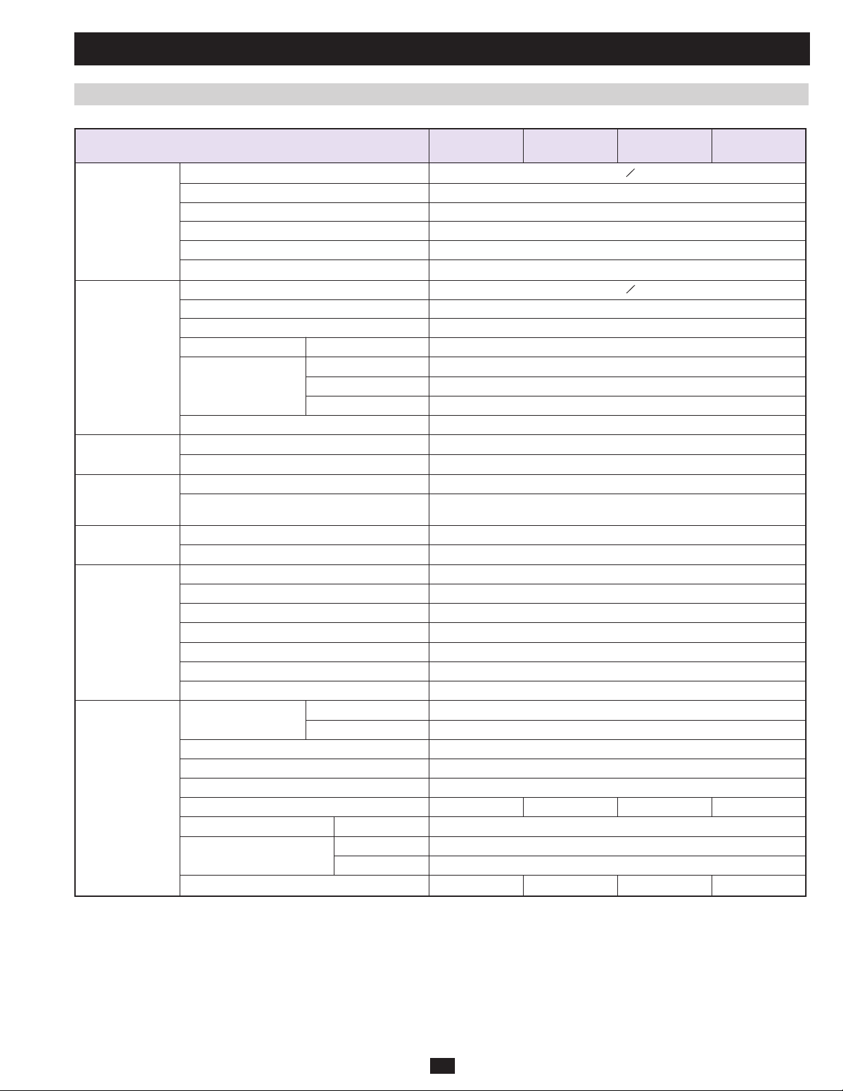
KX Models:
Model SU20KX SU40KX SU60KX SU80KX
(Capacity) (20kVA/16kW) (40kVA/32kW) (60kVA/48kW) (80kVA/64kW)
Input Input Voltage 220/380V, 230/400V or 240/415V AC, 3O, 4-wire + ground, wye
Voltage Regulation -25% ~ +20%
Harmonic Distortion < 5% (Full Load)
PFC (Full Load) > 0.99
Frequency 50 / 60 Hz
Frequency Tolerance 45 ~ 65 Hz
Output Output Voltage 220/380V, 230/400V or 240/415V AC, 3O, 4-wire + ground, wye
Output Frequency 50 / 60 Hz
Total Harmonic (Linear Load) ≤3%
Voltage Regulation Static ±1%
Dynamic ±7% (10% ~ 90% Linear Load)
Frequency Regulation Interior Oscillator ±0.05 Hz
Synchronized ±5%
Overload ≤125% : 10 minutes; ≤150% : 1 minute
Audible Warning Battery Backup Intermittent
UPS Abnormal Continuous
Display LED UPS Status: Normal • Bypass • Backup • Fault
LCD Input/Output • Bypass • Inverter • Frequency • Loading • Battery Voltage
UPS abnormal messages with intelligent self-diagnosis.
Interface Standard RS-232, Dry Contact
Optional SNMPWEBCARD
Others Parallel Redundancy Yes (1+1 for 2 UPS systems of the same type and capacity only.)
PRELIMINARY
EPO Standard (Local and Remote)
SRAM Event Log 500 Records
Parameter Configuration Yes
Hot Standby Installation Optional
Battery Temperature Compensation Optional
Battery Cold-Start Standard
Overall Efficiency Normal 94%
ECO 97%
Transfer Time 0 ms
Temperature 32° F ~ 104° F (0° C ~ 40° C)
Humidity (non-condensing) 90%
Noise (1 m) 65 dBA 68 dBA 70 dBA 70 dBA
Dimensions (Power Module) Width 520 mm
Depth 850 mm
Height 1165 mm
Weight (Power Module) 267 kg* 412 kg* 210 kg 244 kg
3
Page 4
1 Basic Operation (continued)
1.1 Technical Specifi cations (continued)
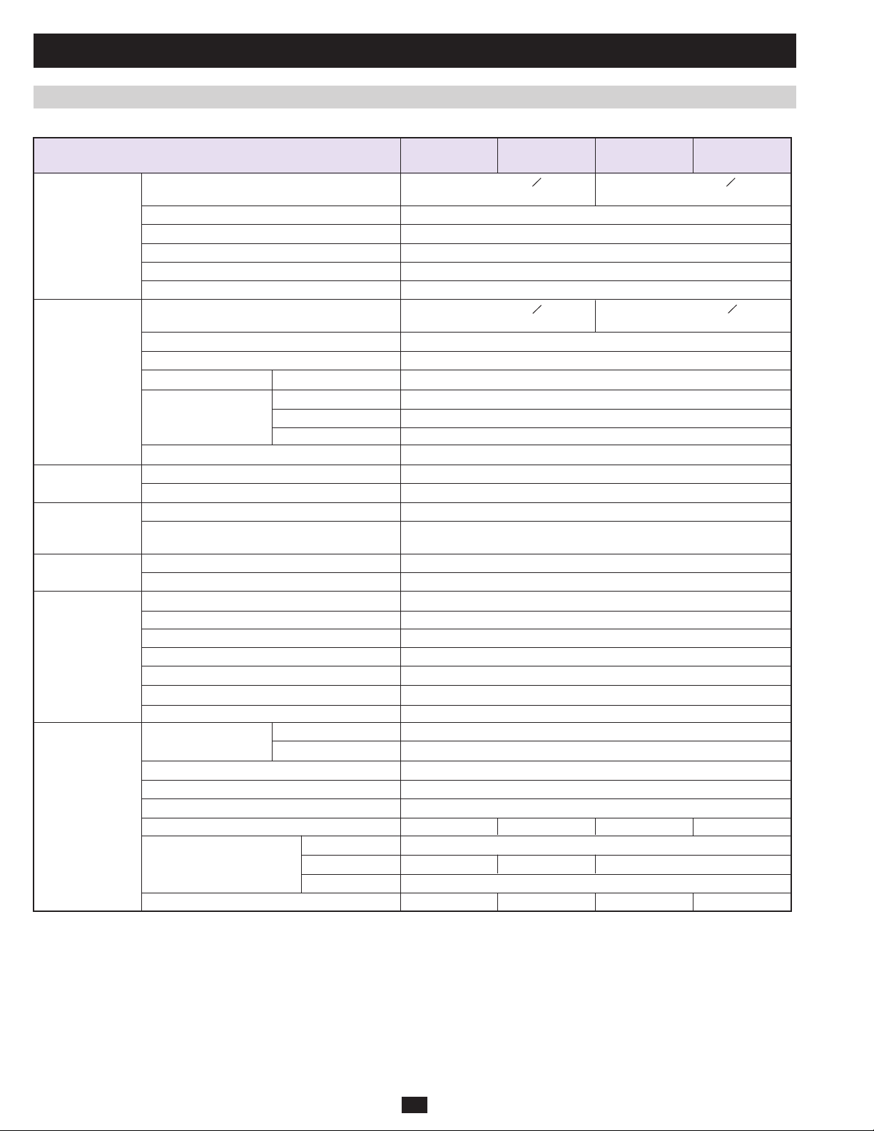
K and KTV Models:
Model SU40K SU60K SU60KTV SU80KTV
(Capacity) (40kVA/32kW) (60kVA/48kW) (60kVA/48kW) (80kVA/64kW)
Input Input Voltage 120/208V AC, 3O, 277/480V AC, 3O,
4-wire + ground, wye 4-wire + ground, wye
Voltage Regulation -25% ~ +20%
Harmonic Distortion < 5% (Full Load)
PFC (Full Load) > 0.99
Frequency 50 / 60 Hz
Frequency Tolerance 45 ~ 65 Hz
Output Output Voltage 120/208V AC, 3O, 277/480V AC, 3O,
4-wire + ground, wye 4-wire + ground, wye
Output Frequency 50 / 60 Hz
Total Harmonic (Linear Load) ≤3%
Voltage Regulation Static ±1%
Frequency Regulation Dynamic ±7% (10% ~ 90% Linear Load)
Interior Oscillator ±0.05 Hz
Synchronized ±5%
Overload ≤125% : 10 minutes; ≤150% : 1 minute
Audible Warning Battery Backup Intermittent
UPS Abnormal Continuous
Display LED UPS Status: Normal • Bypass • Backup • Fault
LCD Input/Output • Bypass • Inverter • Frequency • Loading • Battery Voltage
UPS abnormal messages with intelligent self-diagnosis.
Interface Standard RS-232, Dry Contact
Optional SNMPWEBCARD
Others Parallel Redundancy Yes (1+1 for 2 UPS systems of the same type and capacity only.)
EPO Standard (Local and Remote)
SRAM Event Log 500 Records
Parameter Configuration Yes
Hot Standby Installation Optional
Battery Temperature Compensation Optional
Battery Cold-Start Standard
Overall Efficiency Normal 92%
ECO 96%
Transfer Time 0 ms
Temperature 32° F ~ 104° F (0° C ~ 40° C)
Humidity (non-condensing) 90%
Noise (1 m) 65 dBA 68 dBA 70 dBA 70 dBA
Dimensions (Power Module) Width 520 mm
Depth 850 mm 950 mm 850 mm
Height 1696 mm
Weight (Power Module) 682 kg* 534 kg 534 kg 584 kg
* With internal batteries.
PRELIMINARY
4
Page 5

1 Basic Operation (continued)
1.1 Technical Specifi cations (continued)
SU80K Model:
Model (Capacity) SU80K (80kVA/64kW)
Input Input Voltage 120/208V AC, 3Ø, 4-wire + ground, wye
Voltage Regulation -25% ~ +20%
Harmonic Distortion < 5% (Full Load)
PFC (Full Load) > 0.99
Frequency 50 / 60 Hz
Frequency Tolerance 45 ~ 65 Hz
Output Output Voltage 120/208V AC, 3Ø, 4-wire + ground, wye
Output Frequency 50 / 60 Hz
Total Harmonic (Linear Load) ≤3%
Voltage Regulation Static ±1%
Dynamic ±7% (10% ~ 90% Linear Load)
Frequency Regulation Interior Oscillator ±0.05 Hz
Synchronized ±5%
Overload ≤125% : 10 minutes; ≤150% : 1 minute
Audible Warning Battery Backup Intermittent
UPS Abnormal Continuous
Display LED UPS Status: Normal • Bypass • Backup • Fault
LCD Input/Output • Bypass • Inverter • Frequency • Loading • Battery Voltage
UPS abnormal messages with intelligent self-diagnosis.
Interface Standard RS-232, Dry Contact
Optional SNMPWEBCARD
Others Parallel Redundancy Yes (1+1 for 2 UPS systems of the same type and capacity only.)
EPO Standard (Local and Remote)
SRAM Event Log 500 Records
PRELIMINARY
Parameter Configuration Yes
Hot Standby Installation Optional
Battery Temperature Compensation Optional
Battery Cold-Start Standard
Overall Efficiency Normal 92%
ECO 96%
Transfer Time 0 ms
Temperature 32° F ~ 104° F (0° C ~ 40° C)
Humidity (non-condensing) 90%
Noise (1 m) 70 dBA
Dimensions (Power Module) Width 520 mm
Depth 1026 mm
Height 1696 mm
Weight (Power Module) 655 kg
5
Page 6
1 Basic Operation (continued)
1.2 Features
1.2.1 Advanced Features:
• True on-line double conversion with superior IGBT inverter technology
• Low input current THD allows 1:1 generator sizing for maximum effi ciency and cost savings
• Internal N+1 power module redundancy (except for SU20KX model)
• Built-in parallel redundancy (1+1) capability for increased capacity or fault-tolerance
• Up to 80kVA capacity in a compact footprint; up to 160kVA in parallel redundancy (1+1) confi guration
• High input power factor and high effi ciency with low thermal loss and low noise
• Simplifi ed, easy-to-repair, long-life, high-availability system design
• Redundant auxiliary power and control circuits
• Dual input design with separated rectifi er and bypass input (SU20K, SU40K, SU60K, SU80K only)
• All models support external battery cabinets for extended battery backup runtime
• High-resolution LCD status screen simplifi es operation and delivers detailed operational information, including system block diagrams
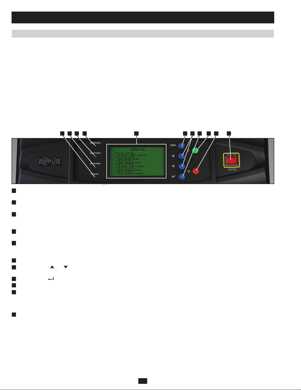
1.2.2 Control Panel Features
A E F G H I J KBCD
“NORMAL” LED:• This green light illuminates to indicate that the UPS system is in online (normal) mode. The primary AC input supply is
A
present and within standard operating parameters.
“BATTERY” LED:• This amber light illuminates when the UPS system is in battery backup mode, discharging the batteries to provide power
B
C
D
E
F
G
H
I
J
K
If the UPS system is in battery backup mode when the EPO button is activated:
If the UPS system is in online (normal) mode when the EPO button is activated:
PRELIMINARY
to connected equipment. An audible alarm will also sound.
“BYPASS” LED:• This amber light illuminates when the UPS system is in bypass mode (auto bypass or manual bypass). Battery backup
power will not be available to connected equipment while the UPS system is in bypass mode, but connected equipment loads will be
supported by the bypass (reserve) power source.
“FAULT” LED:• This red light illuminates when any UPS system or input power fault occurs. Available diagnostic information will be
displayed on the LCD screen.
LCD Status Screen:• This illuminated LCD status screen displays text and graphics to indicate a wide range of UPS system operating
conditions and diagnostic data. Note: The LCD backlight will turn off after 10 minutes of inactivity. Turn on the backlight by momentarily
pressing the ON button or one of the scroll buttons.
“ESC” (Escape) Button:• Press this button to return to the previous page or menu.
Scroll Buttons (•
buttons are also used for data entry in several screens.
Enter Button (• ): Press this button to select a menu item or confirm a setting change.
ON Button:• Press and hold this button for 3 seconds to turn the UPS system’s inverter ON.
OFF Button:• Press and hold this button for 3 seconds to turn the UPS system’s inverter OFF. If the UPS system is in online (normal) mode,
it will switch to auto bypass mode. Note: If the UPS system remains off for an extended period of time, the batteries should be recharged
periodically. The UPS system should be turned on and the batteries should be recharged at least one uninterrupted 24-hour period every
3 months. Failure to recharge the batteries periodically may cause irreversible battery damage.
“EPO” (Emergency Power Off) Button:• Press this button to turn the UPS system’s output OFF and also disable bypass output.
Main output and bypass output are turned off, the alarm sounds, fans shut down after approximately one minute, and control circuitry •
remains active.
Releasing the EPO button (by pressing it again) turns off the UPS system completely, including the alarm and control circuit. Press the •
ON button for 3 seconds to restart the UPS system.
Main output and bypass output are turned off, the alarm sounds, fans and control circuitry remain active.•
Releasing the EPO button (by pressing it again) turns off the alarm and places the UPS system in auto bypass mode. Press the ON button •
for 3 seconds to return the UPS system to online (normal) mode.
and ): Press these buttons to move the cursor up or down and navigate the control panel menus and screens. These
6
Page 7
1 Basic Operation (continued)
1.2 Features (continued)
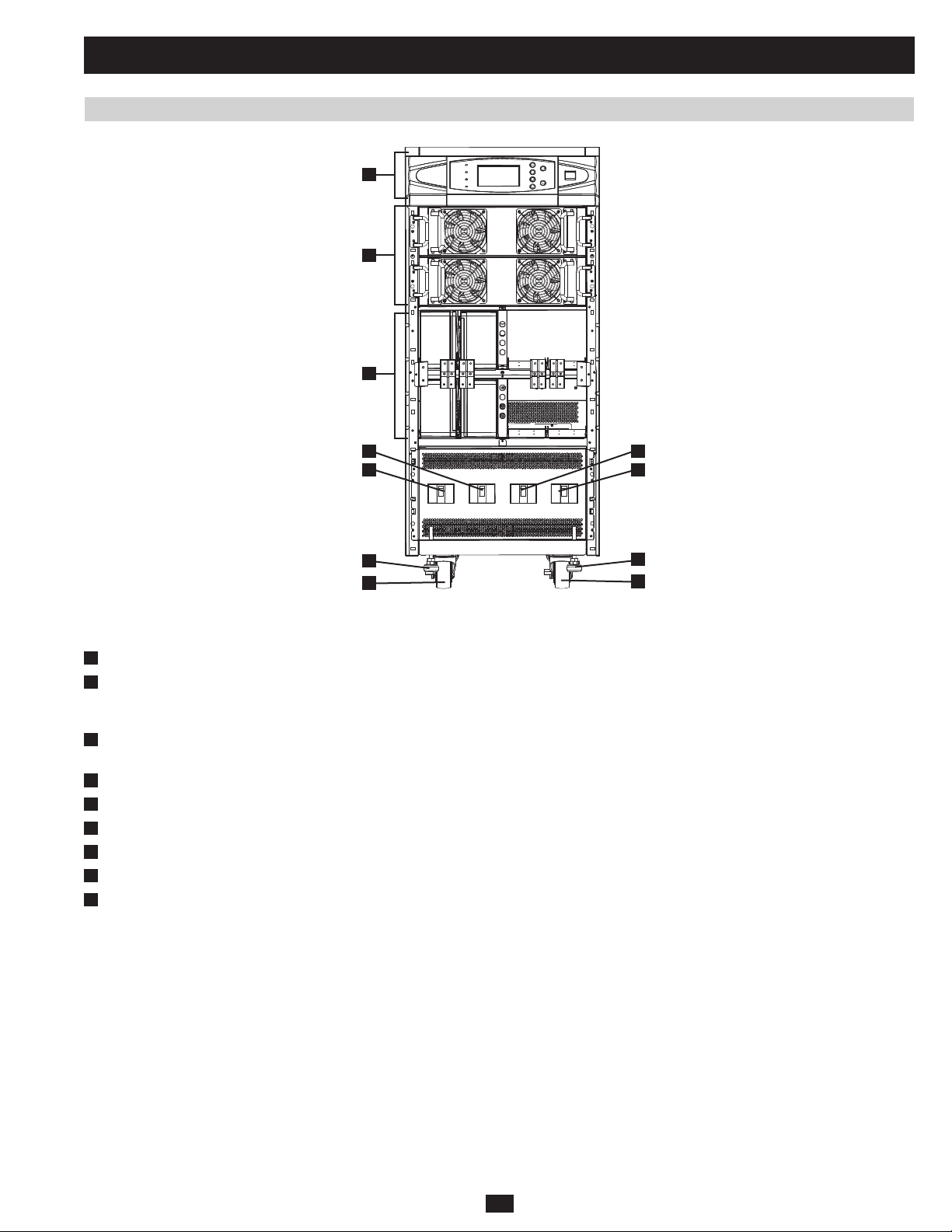
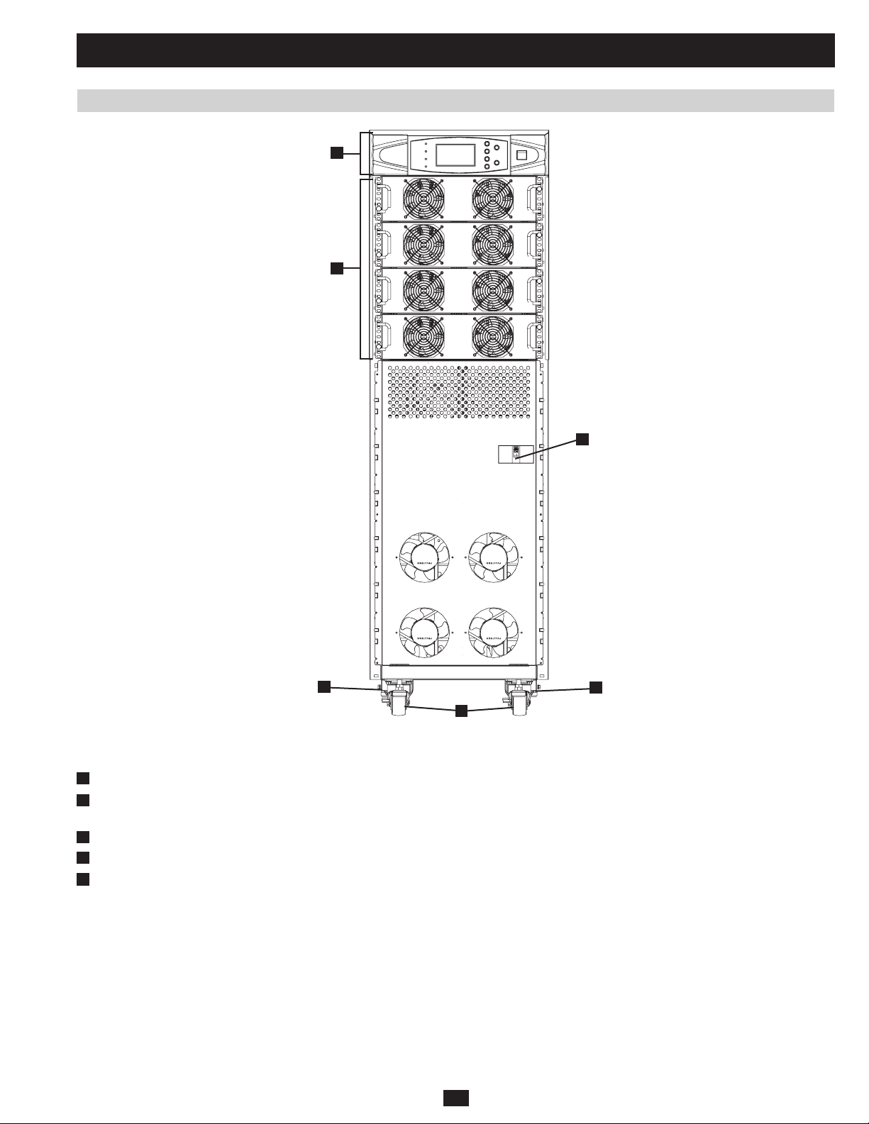
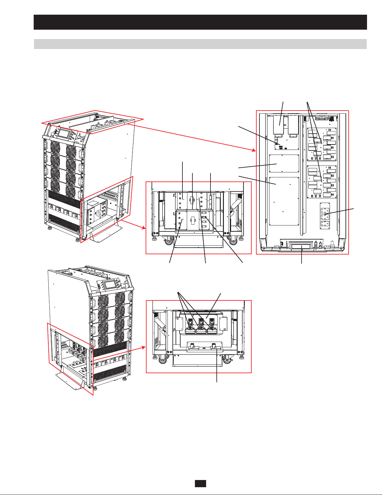
1.2.3 Front and Rear Panel Features
A
B
C
E F
D
G
H
I
Fig 1.2.3a SU40KX front
Note: Individual models may vary from diagrams. Unit shown with front bezels removed.
PRELIMINARY
Control Panel:• The control panel allows the operator to monitor and control the UPS system. (See section 1.2.2 for more information.)
A
Internal Power Modules:• 20kVA internal power modules can be replaced in the field without powering down connected equipment loads. The
B
number of internal power modules varies by model. The internal power modules are capable of N+1 redundancy in SU40KX, SU60KX and
SU80KX models.
Internal Battery Pack Compartment (SU20KX and SU40KX only; shown without batteries):• Internal batteries must be connected by a
C
qualified electrician. (See section 4 for more information.)
Output Circuit Breaker Switch (Q4):• Controls AC output power.
D
Manual Bypass Circuit Breaker Switch (Q3):• Controls AC input power to the UPS system during manual bypass operation.
E
Bypass Input Circuit Breaker Switch (Q2):• Controls AC input power to the UPS system during auto bypass operation.
F
Main Input Circuit Breaker Switch (Q1):• Controls AC input power to the UPS system during online (normal) operation.
G
Levelers:• The levelers provide long-term support for the UPS system.
H
Casters:• The casters are designed for small position adjustments within the final installation location only; they are not designed for moving
I
the UPS system over longer distances. The casters are not designed to provide long-term support for the UPS system after final installation.
Use the levelers to provide long-term support.
H
I
7
Page 8
1 Basic Operation (continued)
1.2 Features (continued)
J
L
H
I I
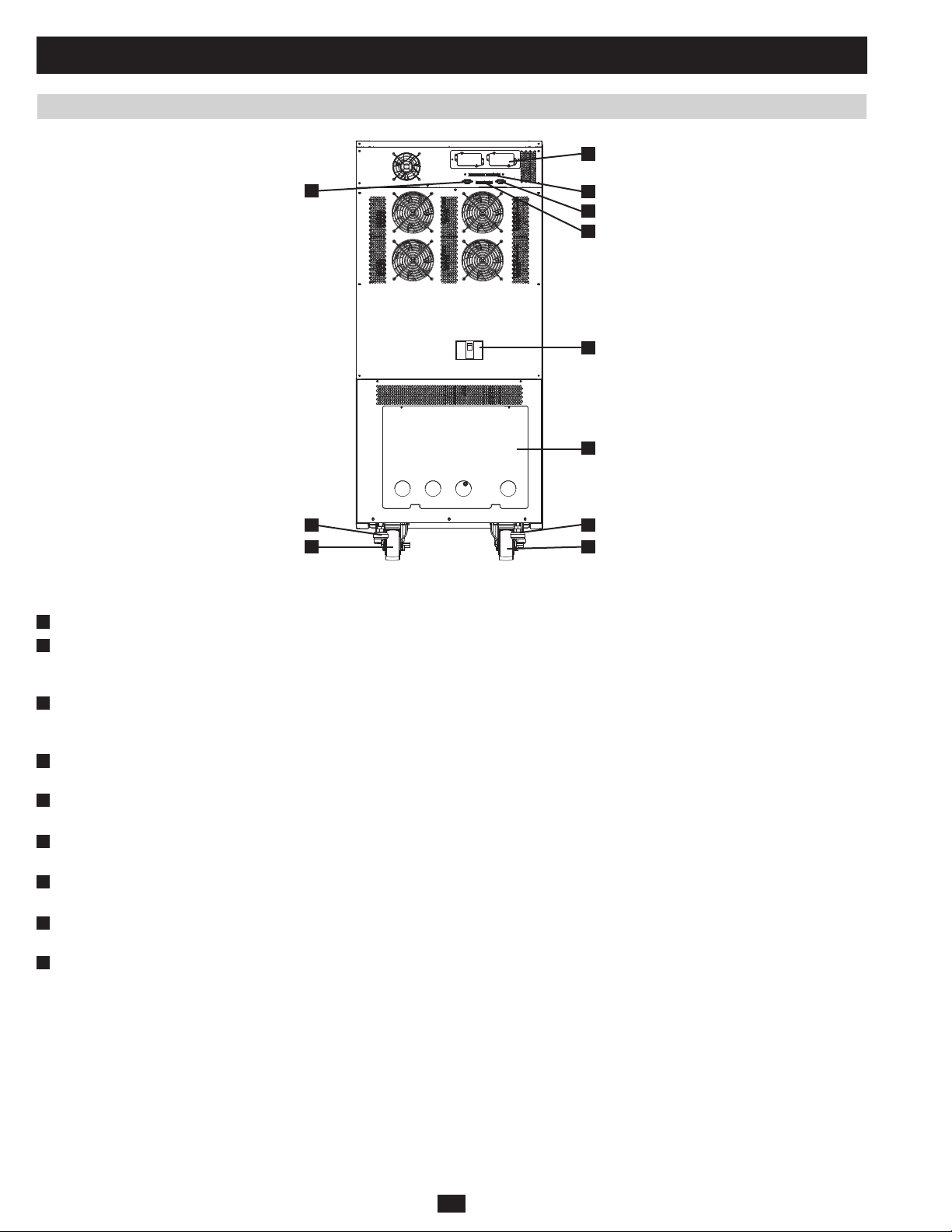
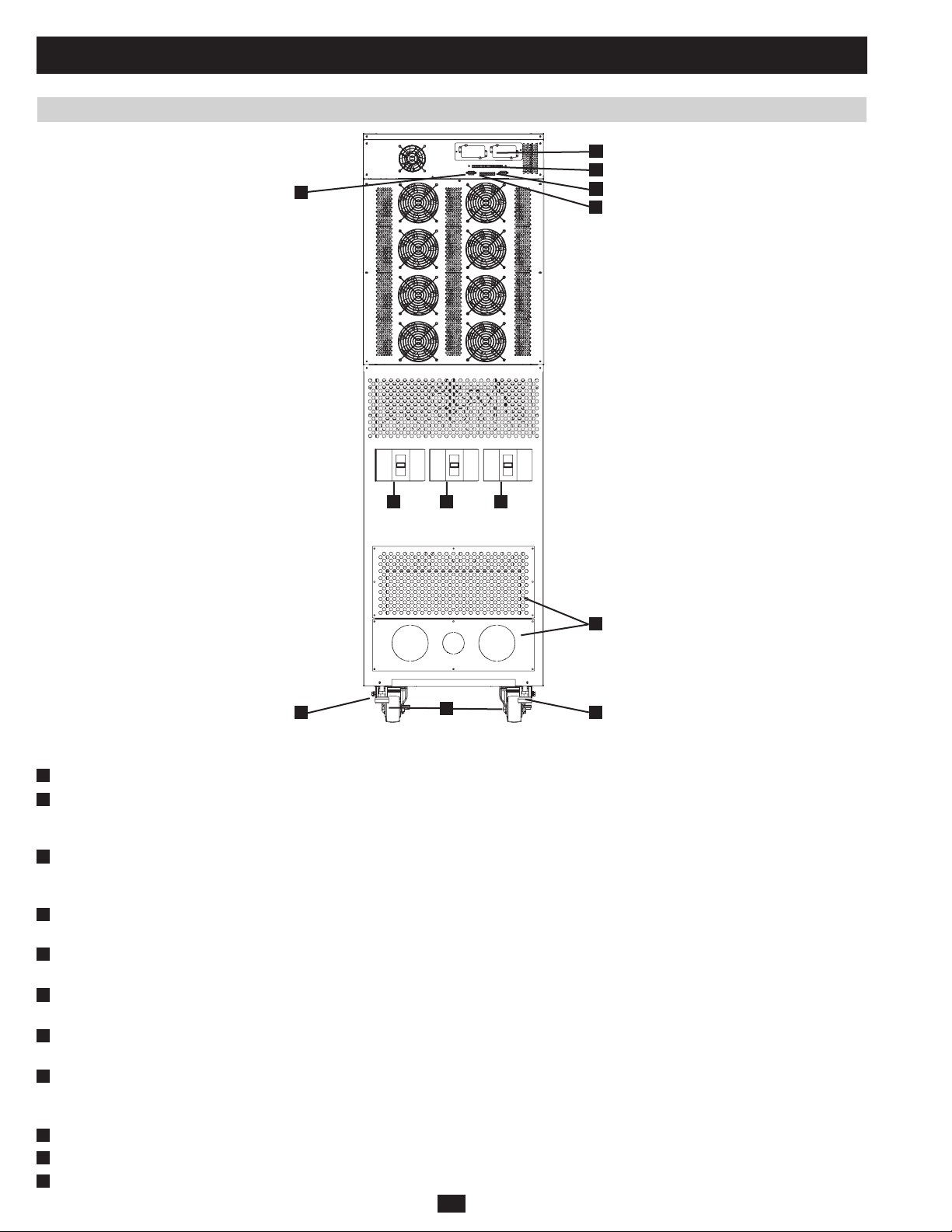
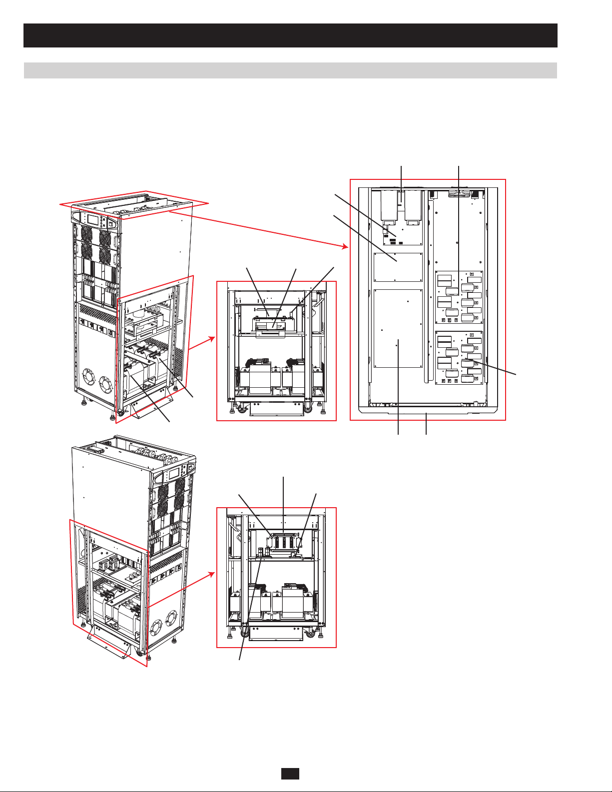
Fig 1.2.3b SU40KX rear
Note: Individual models may vary from diagrams. Unit shown with front bezels removed.
Levelers:• The levelers provide long-term support for the UPS system.
H
Casters:• The casters are designed for small position adjustments within the final installation location only; they are not designed for moving
I
J
K
L
M
N
O
P
PRELIMINARY
the UPS system over longer distances. The casters are not designed to provide long-term support for the UPS system after final installation.
Use the levelers to provide long-term support.
Accessory Slot:• Remove the cover panel to install a Tripp Lite SNMPWEBCARD accessory. The SNMPWEBCARD accessory provides an
Ethernet interface for the UPS system and enables remote monitoring and control via SNMP, Web browser or telnet. Call +1 773 869 1234 for
more information about the SNMPWEBCARD accessory.
RS-232 Serial Communications Port:• This DB9 port connects the UPS system to compatible workstations or servers, enabling automatic
shutdown during extended blackouts and monitoring of operating and power conditions.
Parallel Redundancy Port:• This DB9 port connects the UPS system to another UPS system of identical type and capacity for use in a parallel
redundancy (1+1) configuration. (See sections 1.5 and 1.8 for more information.)
Input Dry Contact Interface:• This interface receives dry contact signals that allow the UPS system to receive commands and monitor
external battery conditions.
Output Dry Contact Interface:• This interface allows the UPS system to send information via dry contact communications. (See section 3.3
for more information.)
Internal Battery Circuit Breaker Switch (SU20KX and SU40KX only):• Controls the input/output power of the UPS system’s internal
batteries.
Terminal Block Cover:• Remove the terminal block cover to access the UPS system’s input, bypass input, external battery cabinet, output and
grounding connection terminals. Wiring conduits pass through the circular knockouts in the terminal block cover. (See section 1.8 for more
information, including a detailed diagram of the terminal block.)
M
K
N
O
P
H
8
Page 9
1 Basic Operation (continued)
1.2 Features (continued)
A
B
C
E
D
F
G
PRELIMINARY
H H
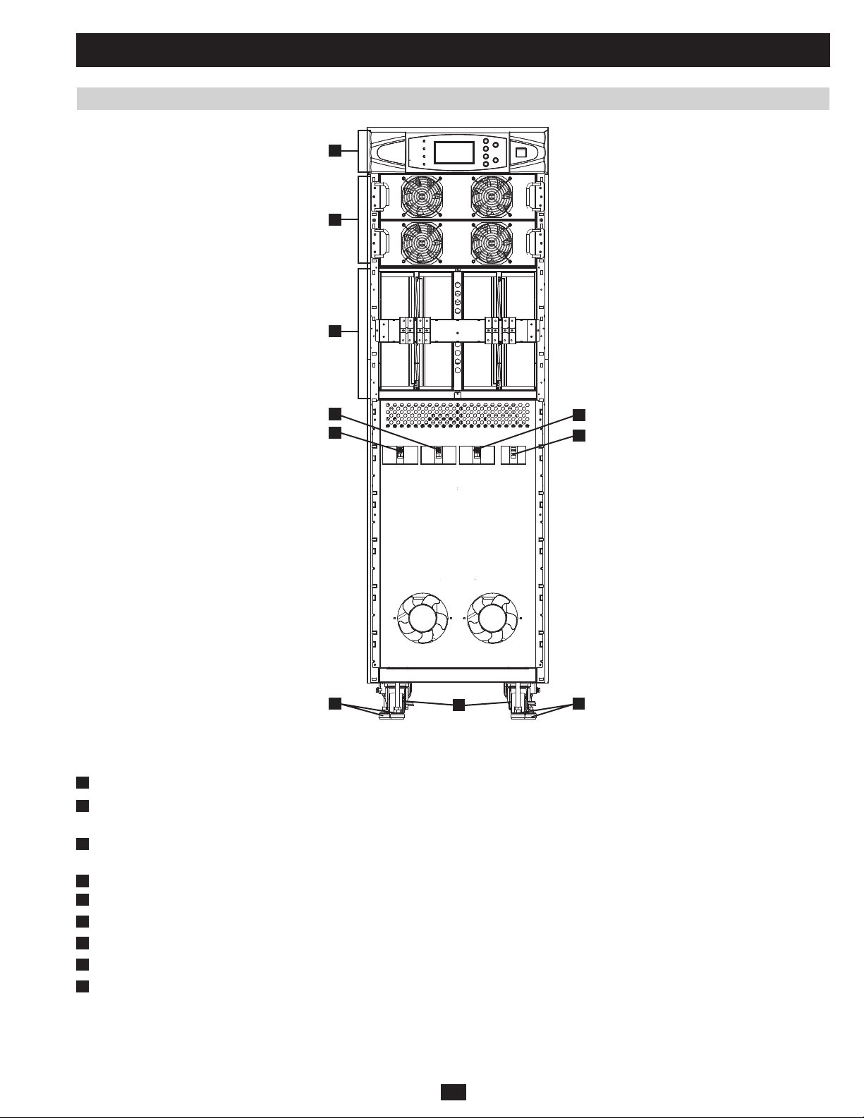
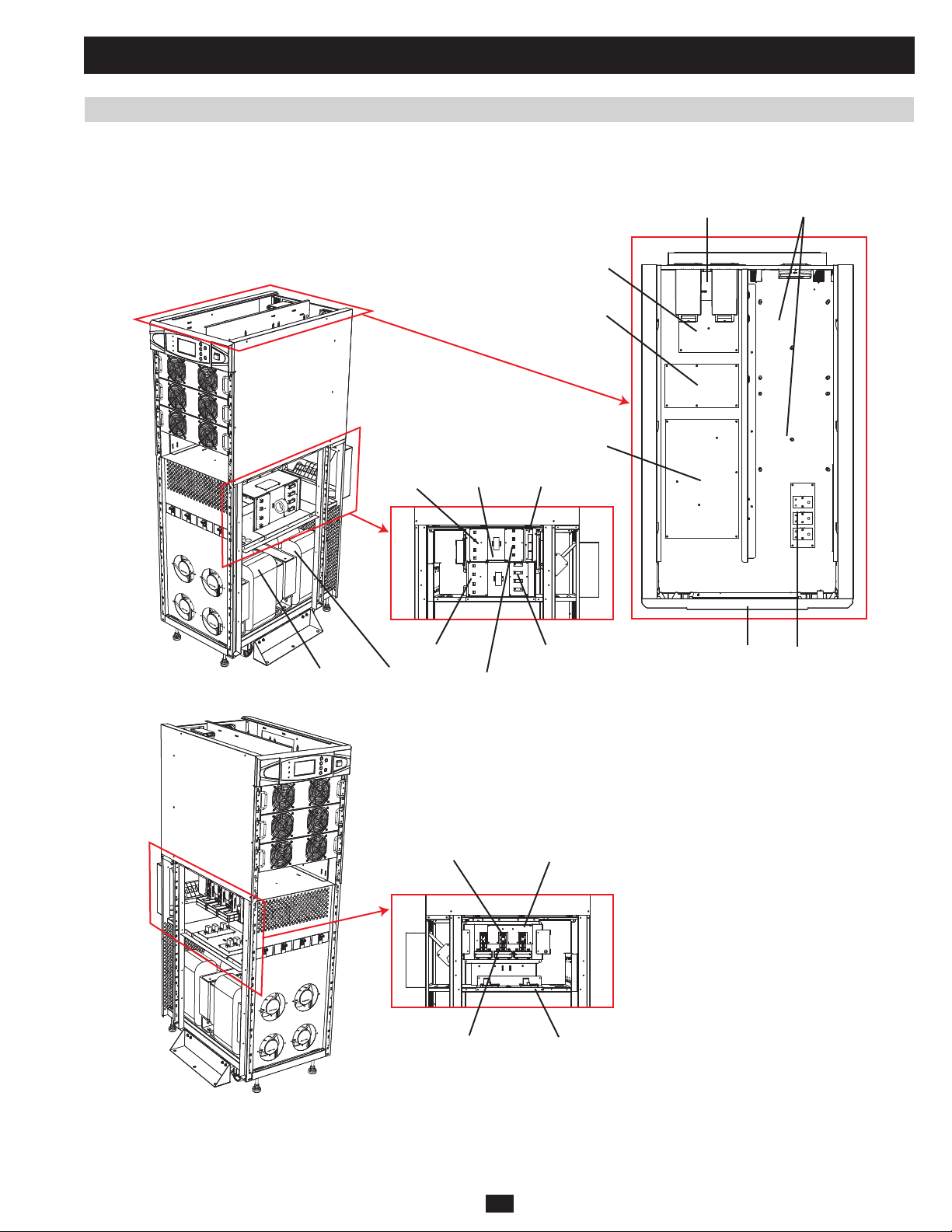
Fig 1.2.3c SU40K front
Note: Individual models may vary from diagrams. Unit shown with front bezels removed.
Control Panel:• The control panel allows the operator to monitor and control the UPS system. (See section 1.2.2 for more information.)
A
Internal Power Modules:• 20kVA internal power modules can be replaced in the field without powering down connected equipment loads. The
B
number of internal power modules varies by model. The internal power modules are capable of N+1 redundancy.
Internal Battery Pack Compartment (SU40K only):• Internal batteries must be connected by a qualified electrician. (See section 4 for more
C
information.)
Output Circuit Breaker Switch (Q4):• Controls AC output power.
D
Manual Bypass Circuit Breaker Switch (Q3):• Controls AC input power to the UPS system during manual bypass operation.
E
Bypass Input Circuit Breaker Switch (Q2):• Controls AC input power to the UPS system during auto bypass operation.
F
Main Input Circuit Breaker Switch (Q1):• Controls AC input power to the UPS system during online (normal) operation.
G
Levelers:• The levelers provide long-term support for the UPS system.
H
Casters:• The casters are designed for small position adjustments within the final installation location only; they are not designed for moving
I
the UPS system over longer distances. The casters are not designed to provide long-term support for the UPS system after final installation.
Use the levelers to provide long-term support.
I
9
Page 10
1 Basic Operation (continued)
1.2 Features (continued)
L
J
M
K
N
O
P
PRELIMINARY
H
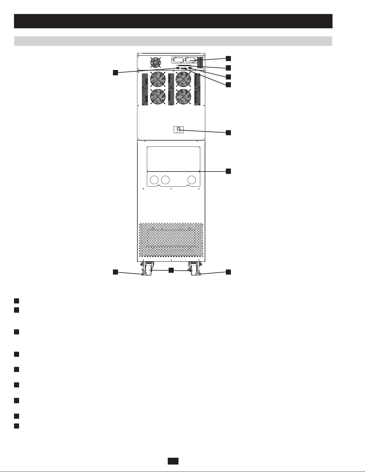
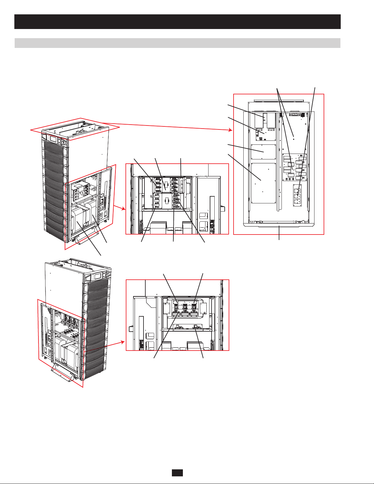
Fig 1.2.3d SU40K rear
Note: Individual models may vary from diagrams. Unit shown with front bezels removed.
H
Levelers:• The levelers provide long-term support for the UPS system.
I
Casters:• The casters are designed for small position adjustments within the final installation location only; they are not designed for moving
the UPS system over longer distances. The casters are not designed to provide long-term support for the UPS system after final installation.
Use the levelers to provide long-term support.
J
Accessory Slot:• Remove the cover panel to install a Tripp Lite SNMPWEBCARD accessory. The SNMPWEBCARD accessory provides an
Ethernet interface for the UPS system and enables remote monitoring and control via SNMP, Web browser or telnet. Call (773) 869-1234 for
more information about the SNMPWEBCARD accessory.
K
RS-232 Serial Communications Port:• This DB9 port connects the UPS system to compatible workstations or servers, enabling automatic
shutdown during extended blackouts and monitoring of operating and power conditions.
L
Parallel Redundancy Port:• This DB9 port connects the UPS system to another UPS system of identical type and capacity for use in a parallel
redundancy (1+1) configuration. (See sections 1.5 and 1.8 for more information.)
M
Input Dry Contact Interface:• This interface receives dry contact signals that allow the UPS system to receive commands and monitor
external battery conditions.
N
Output Dry Contact Interface:• This interface allows the UPS system to send information via dry contact communications. (See section 3.3
for more information.)
O
Internal Battery Circuit Breaker Switch (SU40K only):• Controls the input/output power of the UPS system’s internal batteries.
Terminal Block Cover:• Remove the terminal block cover to access the UPS system’s input, external battery cabinet, output and grounding
P
connection terminals. Wiring conduits pass through the circular knockouts in the terminal block cover. (See section 1.8 for more information,
including a detailed diagram of the terminal block.)
I
H
10
Page 11
1 Basic Operation (continued)
1.2 Features (continued)
A
B
C
PRELIMINARY
D
E
Fig 1.2.3e SU80K front
Note: Individual models may vary from diagrams. Unit shown with front bezels removed.
Control Panel:• The control panel allows the operator to monitor and control the UPS system. (See section 1.2.2 for more information.)
A
Internal Power Modules:• 20kVA internal power modules can be replaced in the field without powering down connected equipment loads. The
B
number of internal power modules varies by model. The internal power modules are capable of N+1 redundancy.
Main Input Circuit Breaker Switch (Q1):• Controls AC input power to the UPS system during online (normal) operation.
C
D
Levelers:• The levelers provide long-term support for the UPS system.
E
Casters:• The casters are designed for small position adjustments within the final installation location only; they are not designed for moving
the UPS system over longer distances. The casters are not designed to provide long-term support for the UPS system after final installation.
Use the levelers to provide long-term support.
D
11
Page 12
1 Basic Operation (continued)
1.2 Features (continued)
H
F
I
G
J
L
M N
K
PRELIMINARY
D
Fig 1.2.3f SU80K rear
Note: Individual models may vary from diagrams. Unit shown with breaker guard removed.
D
Levelers:• The levelers provide long-term support for the UPS system.
E
Casters:• The casters are designed for small position adjustments within the final installation location only; they are not designed for moving
the UPS system over longer distances. The casters are not designed to provide long-term support for the UPS system after final installation.
Use the levelers to provide long-term support.
F
Accessory Slot:• Remove the cover panel to install a Tripp Lite SNMPWEBCARD accessory. The SNMPWEBCARD accessory provides an
Ethernet interface for the UPS system and enables remote monitoring and control via SNMP, Web browser or telnet. Call (773) 869-1234 for
more information about the SNMPWEBCARD accessory.
G
RS-232 Serial Communications Port:• This DB9 port connects the UPS system to compatible workstations or servers, enabling automatic
shutdown during extended blackouts and monitoring of operating and power conditions.
H
Parallel Redundancy Port:• This DB9 port connects the UPS system to another UPS system of identical type and capacity for use in a parallel
redundancy (1+1) configuration. (See sections 1.5 and 1.8 for more information.)
I
Input Dry Contact Interface:• This interface receives dry contact signals that allow the UPS system to receive commands and monitor
external battery conditions.
J
Output Dry Contact Interface:• This interface allows the UPS system to send information via dry contact communications. (See section 3.3
for more information.)
K
Terminal Block Cover:• Remove the terminal block cover to access the UPS system’s input, external battery cabinet, output and grounding
connection terminals. Wiring conduits pass through the circular knockouts in the terminal block cover. The UPS system includes alternate
circular knockouts in the bottom panel. (See section 1.8 for more information, including a detailed diagram of the terminal block.)
L
Bypass Input Circuit Breaker Switch (Q2):• Controls AC input power to the UPS system during auto bypass operation.
M
Manual Bypass Circuit Breaker Switch (Q3):• Controls AC input power to the UPS system during manual bypass operation.
N
Output Circuit Breaker Switch (Q4):• Controls AC output power.
E
12
D
Page 13
1 Basic Operation (continued)
1.3 Operating Principles
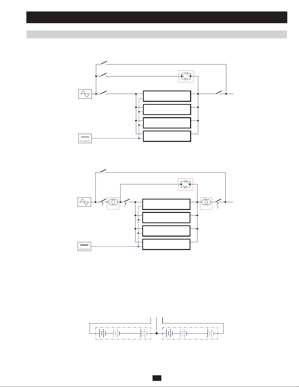
1.3.1 System Layout
MAIN
BATTERY
Q3
Manual Bypass
Circuit Breaker
Q2
Bypass Input
Circuit Breaker
Q1 LOAD
Main Input
Circuit Breaker
Main
Manual Input
Bypass Input
20kVA/3U POWER MODULE
20kVA/3U POWER MODULE
20kVA/3U POWER MODULE
20kVA/3U POWER MODULE
STS
Output
Circuit Breaker
Fig 1.3.1a System Block Diagram for KX models
Q3
Manual Bypass
Circuit Breaker
Manual Input
Bypass Input
Q4
STS
Q4
Output
LOAD
PRELIMINARY
MAIN
BATTERY
Bypass Input
Circuit Breaker
XFMR XFMR
Q2
Q1
Main Input
Circuit Breaker
Fig 1.3.1b System Block Diagram for K and KTV models
20kVA/3U POWER MODULE
20kVA/3U POWER MODULE
20kVA/3U POWER MODULE
20kVA/3U POWER MODULE
Circuit Breaker
The SU-Series 3-Phase UPS is confi gured with 3-phase 20kVA power modules that can be paralleled for redundancy or capacity upgrades. Each
KX- (Figure 1.3.1a), K- , and KTV-series (Figure 1.3.1b) UPS includes three key functions:
1) A central bypass static switch, which causes a critical load to automatically bypass any overload or fault conditions that occur.
2) A maintenance bypass switch, which eliminates UPS faults by supplying a critical load.
3) A matched transformer, which increases and decreases the input/output voltage
1.3.2 Internal Battery Layout
B+ N B-
12Vdc, 20pcs 12Vdc, 20pcs
Fig 1.3.2a Battery Strings
An internal battery pack (number of packs vary by model) supplies the UPS system with battery backup power. Each internal battery pack consists
of 40 12Vdc VRLA batteries arranged in two strings: one string of 20 positive batteries (black cable) and one string of 20 negative batteries (red
cable). The two strings are connected by a neutral (N) point (Figure 1.3.2a).
13
Page 14
1 Basic Operation (continued)
1.3 Operating Principles (continued)
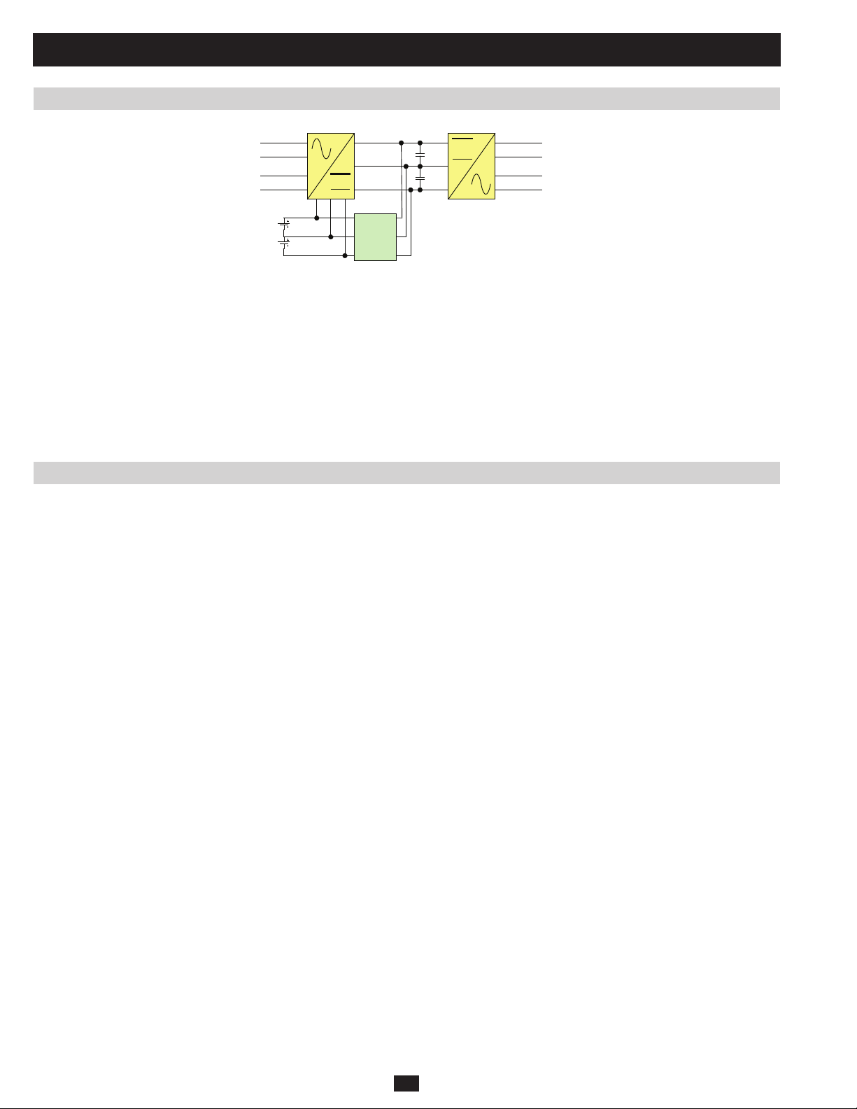
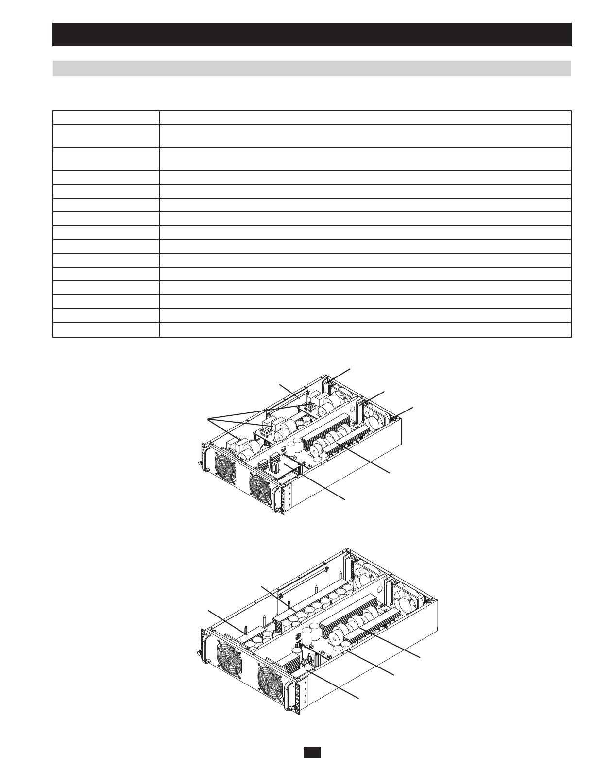
1.3.3 Power Module Layout
The SU-Series 3-Phase UPS double-conversion power modules consist of three components (Figure 1.3.3a):
1) An AC/DC converter
2) An AC/DC inverter
3) A charger
The power module’s 3-phase, 4-wire input runs A/C current through the AC/DC converter to generate regulative dual DC bus (±370Vdc). During
backup mode, this current is provided by battery power.
The dual DC bus then runs through the AC/DC inverter to generate a pure sine wave of AC power (3-phase, 4-wire). The DC bus also charges the
dual battery strings by running current through the charger. Each power module has a maximum charge current of 5 A.
R
S
INPUT OUTPUT
T
N
BATTERY
Fig 1.3.3a Power Module Block Diagram
Charger
U
V
W
N
1.4 Opening and Closing the Unit
[PENDING]
PRELIMINARY
14
Page 15
1 Basic Operation (continued)
1.5 Operating Modes
This section provides a basic description of the UPS system’s operating modes. For more information about switching between operating modes,
refer to Section 1.6 – Start-Up, Shutdown and Bypass.
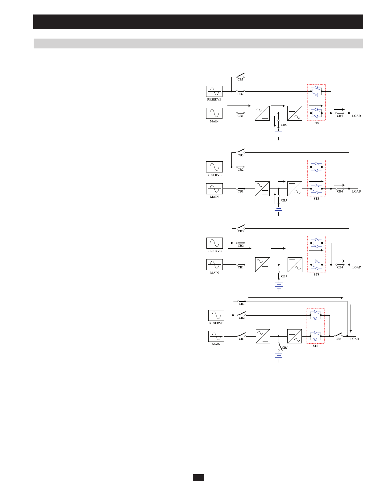
1.5.1 Online (Normal) Mode (Single UPS)
In online (normal) mode, the UPS system’s rectifier converts incoming
AC utility power to DC power that charges the batteries and supplies the
inverter. The inverter transforms the DC power to precision-regulated,
pure sine wave AC power that supports the operation of connected
equipment. This dual conversion technology isolates connected
equipment from all power problems and ensures that connected
equipment receives ideal power at all times.
1.5.2 Battery Backup Mode (Single UPS)
When a blackout or other extreme power event occurs, the UPS system
automatically switches from normal mode to battery backup mode. The
UPS system’s batteries (internal and/or external) provide emergency DC
power to the inverter. The inverter transforms the DC power to precisionregulated, pure sine wave AC power that supports the operation of
connected equipment.
1.5.3 Auto Bypass Mode (Single UPS)
If the inverter malfunctions due to excessive temperature, overload,
output short circuit, abnormal voltage or battery problems, the inverter
will shut down. If the UPS system detects a bypass (reserve) power
source that conforms to normal parameters, then the UPS system
automatically switches to auto bypass mode to continue supplying power
PRELIMINARY
to connected equipment. When all problems are eliminated, the UPS
system switches back to online (normal) mode automatically.
1.5.4 Manual Bypass Mode (Single UPS)
If UPS system maintenance or repair is required, you can bypass
the UPS system and enable bypass (reserve) power manually. After
confirming that bypass (reserve) power is present, switch the UPS
system into manual bypass mode. This allows service technicians to
perform maintenance or repair jobs without interrupting the flow of AC
power to connected equipment. Warning: The UPS system must be
de-energized completely before performing maintenance or repair
by shutting it down completely after switching it to manual bypass
mode.
15
Page 16
1 Basic Operation (continued)
1.5 Operating Modes (continued)
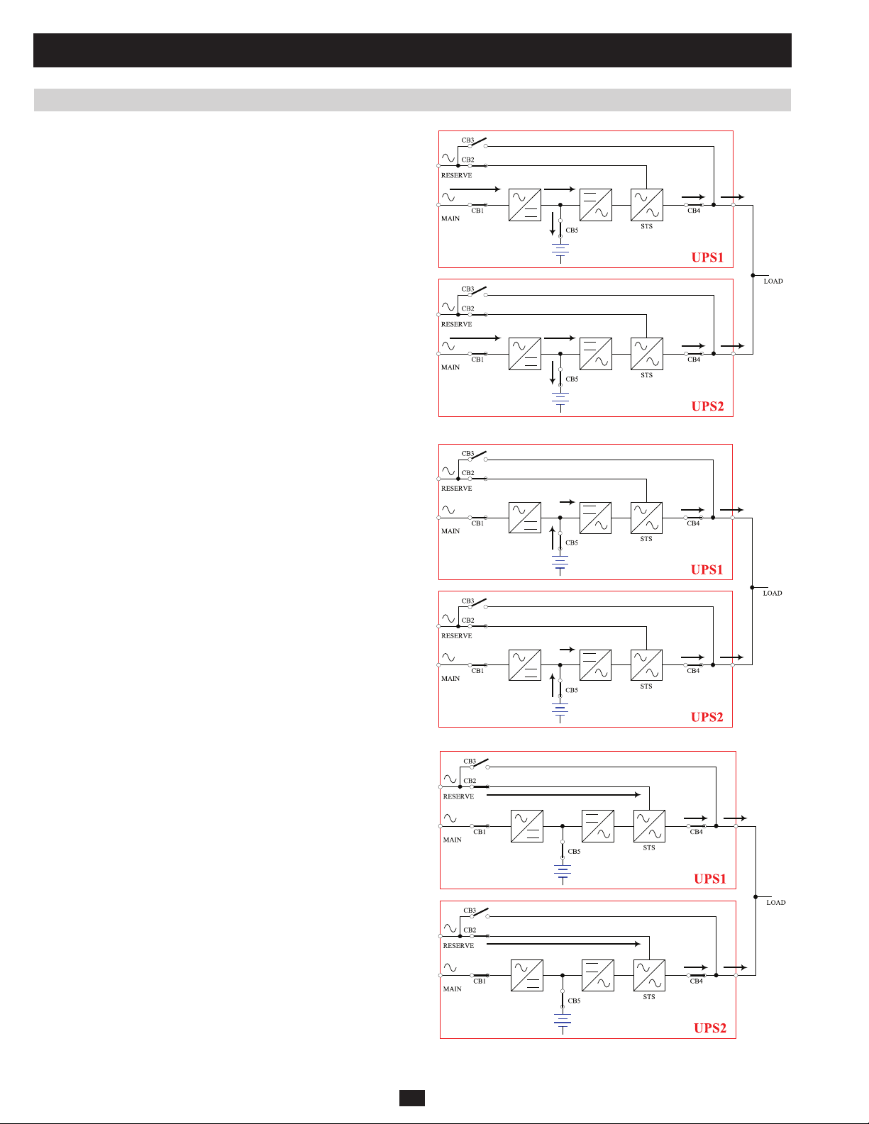
1.5.5 Online Mode (Parallel UPS)
Parallel redundancy (1+1) provides UPS system redundancy or increased
total capacity. Under parallel redundancy, the total load is shared by
two UPS systems. If one of the UPS systems malfunctions, the total
connected equipment load is supported by the remaining UPS system. If
the total load exceeds the capacity of the remaining UPS system, it will
switch to auto bypass mode.
1.5.6 Battery Backup Mode (Parallel UPS)
Similar to on battery backup mode for a single UPS system (Section
1.5.2), except the total connected equipment load is shared by the parallel
(1+1) UPS systems.
PRELIMINARY
1.5.7 Auto Bypass Mode (Parallel UPS)
Similar to auto bypass mode for a single UPS system (Section 1.5.3),
except with parallel (1+1) UPS systems.
16
Page 17
1 Basic Operation (continued)
1.5 Operating Modes (continued)
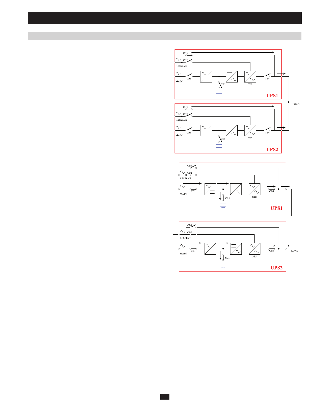
1.5.8 Manual Bypass Mode (Parallel UPS)
Similar to manual bypass mode for a single UPS system (Section 1.5.4),
except with parallel (1+1) UPS systems. Note: Both UPS systems must
be switched into manual bypass mode.
1.5.9 Hot Standby Mode (Parallel UPS)
For added fault-tolerance, the redundant UPS system acts as the bypass
(reserve) power source for the main UPS system.
PRELIMINARY
17
Page 18
1 Basic Operation (continued)
1.6 Start-Up, Shutdown and Bypass
Warning: The UPS system’s output voltage is set at 220/380V by default. If you require output voltage of 230/400V or 240/415V, you must
change the UPS system’s output voltage by accessing the output setup menu described in Section 10-9 of the owner’s manual. You must
place the UPS system in bypass mode before changing the output voltage. Do not connect your equipment to the UPS system’s output until
you have set the proper parameters.
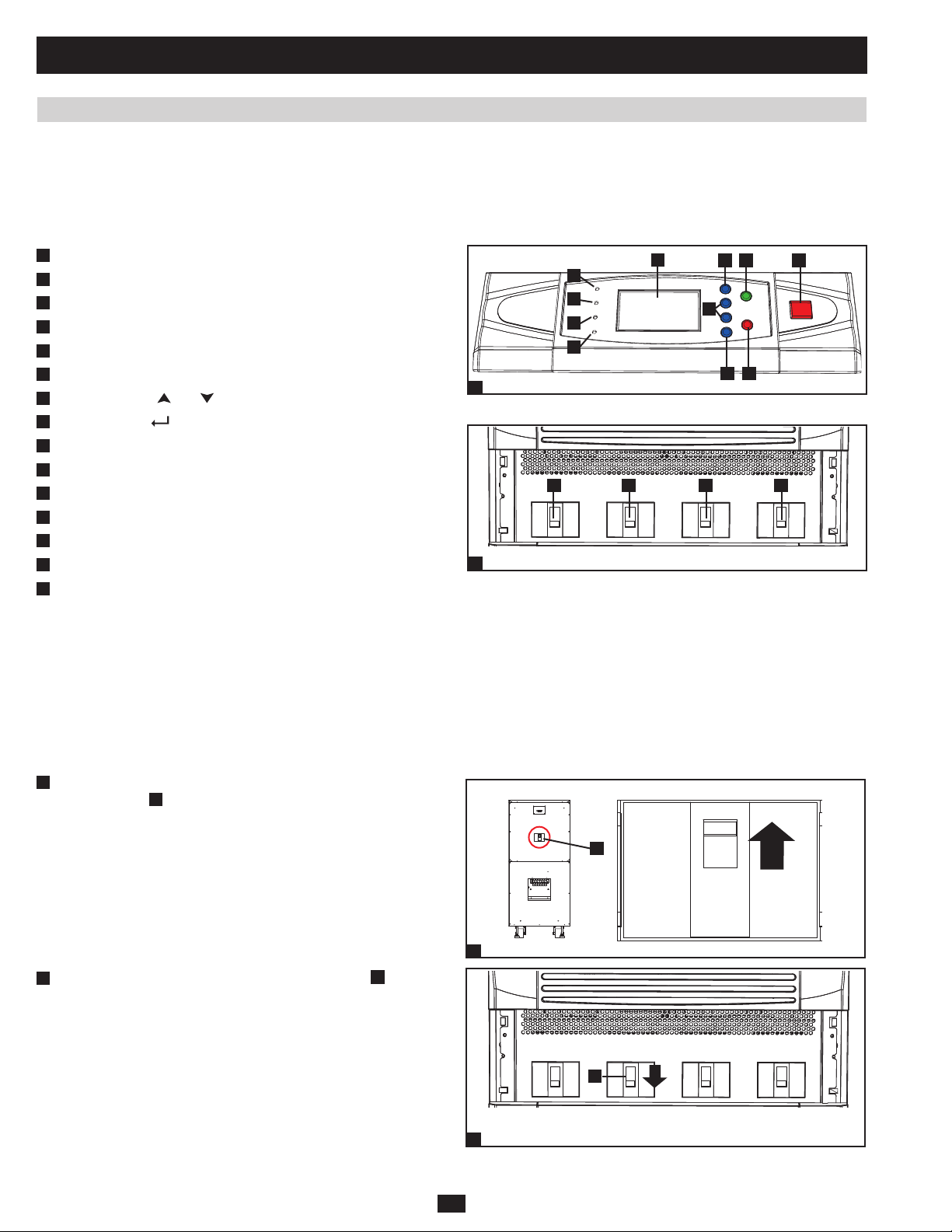
1.6.1 Control Panel and Breaker Diagrams
“NORMAL” LED•
A
“BATTERY” LED•
B
C
“BYPASS” LED•
“FAULT” LED•
D
LCD Status Screen•
E
F
“ESC” (Escape) Button•
Scroll Buttons (•
G
H
Enter Button (• )
I
ON Button•
OFF Button•
J
K
“EPO” (Emergency Power Off) Button•
Output Circuit Breaker Switch•
L
M
Manual Bypass Circuit Breaker Switch•
N
Bypass Input Circuit Breaker Switch•
Main Input Circuit Breaker Switch•
O
and )
A
B
C
D
1
L
Output
2
Circuit Breaker Switches (UPS System Front Panel)
E
Control Panel
M
Manual
Bypass
G
N
Bypass
Input
F
I
J
H
O
Main
Input
K
1.6.2 Preliminary Checklist (Single UPS)
• All circuit breaker switches should be off, including the breaker of the external battery cabinet (if present).
PRELIMINARY
• Confi rm that no voltage potential exists between Neutral and Ground.
• Confi rm that the input power source matches the rating (voltage, frequency and phase) of the UPS system.
Note: After start-up, the UPS system will perform a brief self-test and display the results on the LCD screen. After a successful self-test, the UPS
system will provide AC power to the connected equipment load.
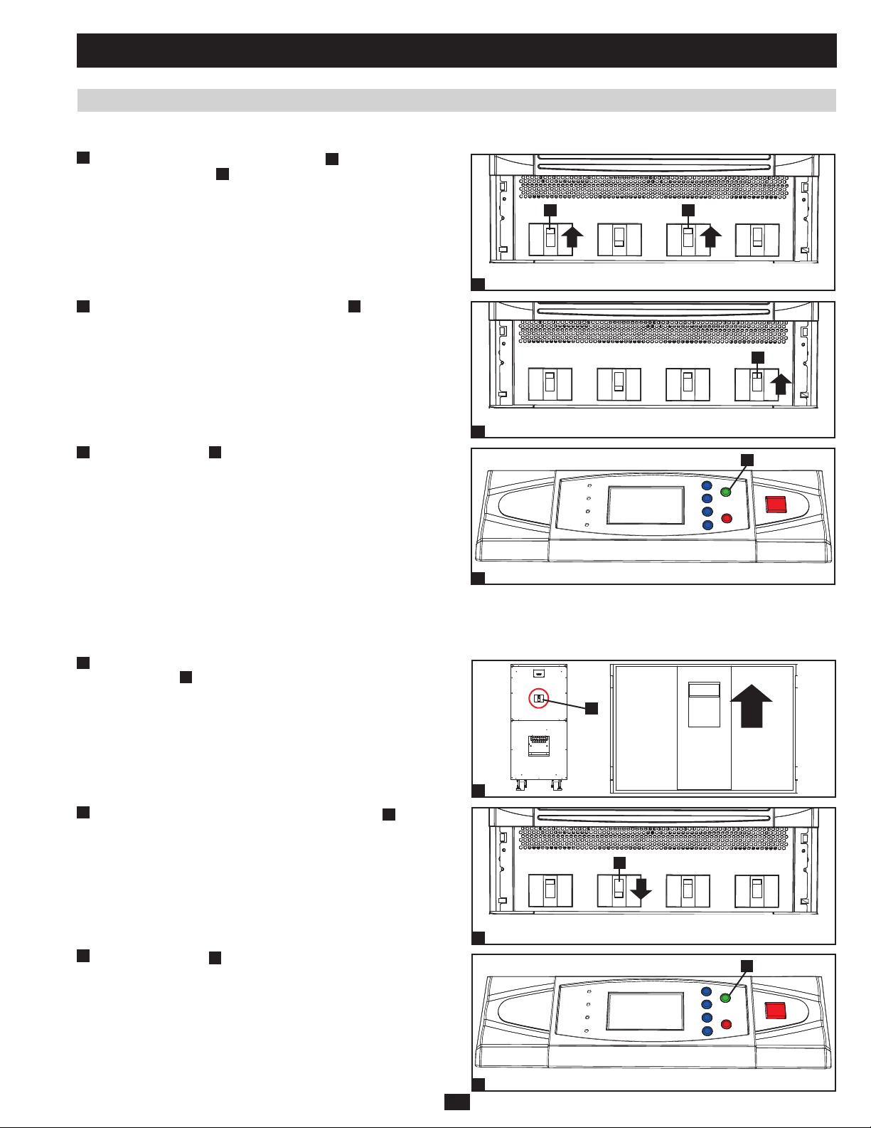
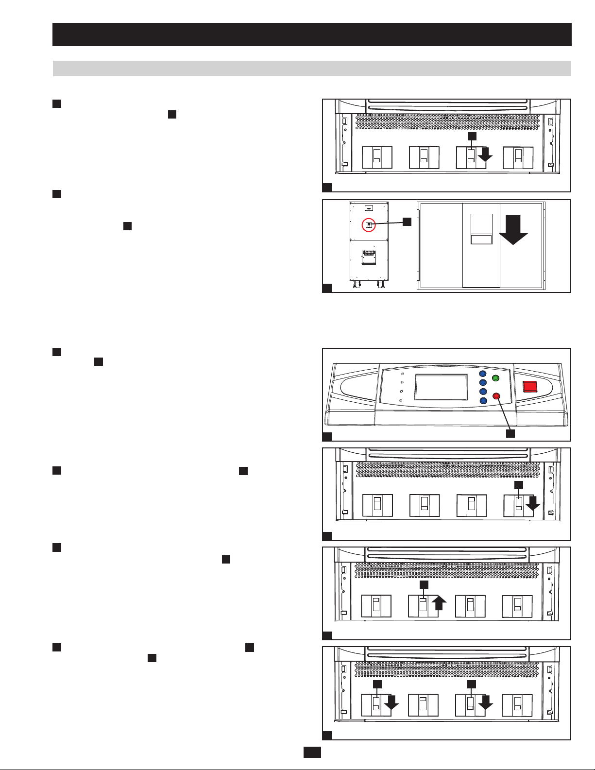
1.6.3 Standard Start-Up Procedure (Single UPS)
1
If there is an external battery cabinet connected, switch on the •
circuit breaker
Confirm that the manual bypass circuit breaker switch •
2
A
of the external battery cabinet.
A
is off.
A
1
18
A
Output
2
Manual
Bypass
Bypass
Input
Main
Input
Page 19
1 Basic Operation (continued)
1.6 Start-Up, Shutdown and Bypass (continued)
1.6.3 Standard Start-Up Procedure (Single UPS) (continued)
3
Switch on the output circuit breaker switch •
circuit breaker switch B. After a brief initialization process, the
LCD screen will show “ON AUTO BYPASS”, the “BYPASS”
LED will illuminate and UPS system output will be supplied by the
bypass (reserve) power source.
A
and bypass input
A B
Output Manual
3
Switch on the main input circuit breaker switch •
4
A
. If the AC input
Bypass
Bypass
Input
Main
Input
power source is normal, the UPS system is ready for start-up.
A
5
Press the ON button •
A
for 3 seconds (until you hear a beep), then
release the button. The inverter will activate and synchronize with
Output Manual
4
Bypass
Bypass
Input
A
Main
Input
the bypass source, then automatically switch from auto bypass
(reserve) mode to online (normal) mode. The “BYPASS” LED will
darken and the “NORMAL” LED will illuminate.
5
PRELIMINARY
1.6.4 Battery Start-Up Procedure (Single UPS)
Note: The battery must be at least partially charged for this operation to succeed.
If there is an external battery cabinet connected, switch on the •
1
A
circuit breaker
of the external battery cabinet.
2
Confirm that the manual bypass circuit breaker switch •
3
Press the ON button •
A
for 3 seconds (until you hear a beep), then
release the button. The inverter will activate and use stored DC
battery power to supply AC power to connected equipment. The
“BATTERY” LED will illuminate.
A
is off.
19
A
1
A
Output Manual
2
3
Bypass
Bypass
Input
Input
A
Main
Page 20
1 Basic Operation (continued)
1.6 Start-Up, Shutdown and Bypass (continued)
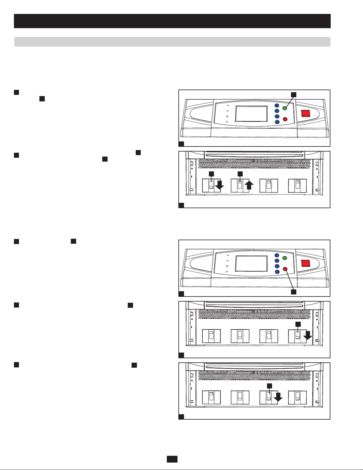
1.6.5 Manual Bypass Procedure (Single UPS)
Warning: Placing the UPS system in manual bypass will disable the inverter and power all loads from the manual bypass (reserve) source,
but the UPS system will still be energized. Before performing maintenance or repair on the UPS system, shut down and de-energize the
UPS system completely by following the steps in Section 1.6.6. Although connected equipment loads will be powered by the bypass (reserve)
power source, they will not receive battery backup in the event of a utility power failure.
1
When the UPS system is in online (normal) mode, press the ON •
A
button
for 3 seconds (until you hear a beep), then release the
button. The inverter will automatically switch to bypass mode and
the “BYPASS” LED will illuminate.
Switch on the manual bypass circuit breaker switch •
2
off the output circuit breaker switch
B
.
A
, then switch
1
AB
A
Output Manual
2
Bypass
Bypass
Input
Main
Input
1.6.6 Shutdown Procedure (Single UPS)
Warning: The UPS system shutdown procedure will eliminate the AC power output for all loads. Before shutdown, confirm that all loads
are turned off or place the UPS system in manual bypass mode to keep loads powered by the reserve (bypass) power source.
Press the OFF button •
1
release the button. If the UPS system is in online (normal) mode, it
PRELIMINARY
A
for 3 seconds (until you hear a beep), then
will switch to bypass mode. If the UPS system is in battery backup
mode, the inverter will shut down and AC output power will be
interrupted.
1
2
Switch off the main input circuit breaker switch •
3
Switch off the bypass input circuit breaker switch •
A
.
Output
2
A
.
Manual
Bypass
Bypass
Input
A
A
Main
Input
20
A
3
Output
Manual
Bypass
Bypass
Input
Main
Input
Page 21
1 Basic Operation (continued)
1.6 Start-Up, Shutdown and Bypass (continued)
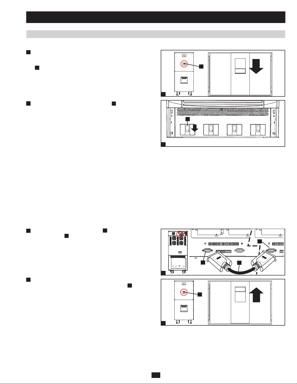
1.6.6 Shutdown Procedure (Single UPS) (continued)
4
Confirm that the UPS system is off and that all main output circuits •
are off. If the UPS system is connected to an external battery
cabinet, turn off the external battery cabinet circuit breaker switch
A
.
A
4
5
Switch off the output circuit breaker switch •
power source is normal, the UPS system is ready for start-up.
Note: If the UPS system remains off for an extended period of time, it
should be turned on periodically to allow the batteries to recharge. The
UPS system should be turned on and the batteries should be recharged
at least one uninterrupted 24-hour period every 3 months. Failure
to recharge the batteries periodically may cause irreversible battery
damage.
1.6.7 Preliminary Checklist (Parallel UPS)
Warning: Parallel redundancy requires exactly two UPS systems (1+1 redundancy ). Do not attempt to link more than two UPS systems
via parallel redundancy. The UPS systems must have the same rating and capacity for parallel redundancy installation. Attempting to link
dissimilar UPS systems will damage the UPS systems and create a serious risk of personal injury and property damage.
All circuit breaker switches should be off, including the breakers of the external battery cabinets.•
Confirm that no voltage potential exists between Neutral and Ground.•
Confirm that the input power source matches the rating (voltage, frequency and phase) of the UPS systems.•
You must use the control panel to set the parallel ID numbers of the UPS systems to be 1 and 2. See section 10-11 of the owner’s •
manual for information about setting the parallel ID numbers.
PRELIMINARY
Note: After start-up, the UPS systems will perform a brief self-test and display the results on the LCD screen. After a successful self-test, the UPS
systems will provide AC power to the connected equipment load.
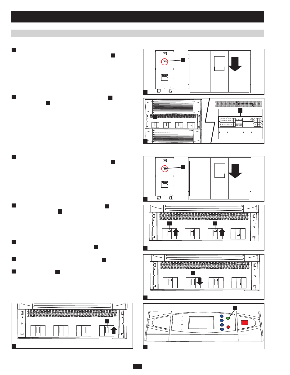
1.6.8 Start-Up Procedure (Parallel UPS)
Connect the parallel redundancy cable •
1
redundancy port B of each UPS system.
A
. If the AC input
A
to the DB9 parallel
A
Output Manual
5
Bypass
Bypass
Input
Main
Input
B
2
If the UPS systems have external battery cabinets connected, switch •
on the external battery cabinet circuit breaker switch
battery pack.
A
of each
21
B
1
A
2
A
Page 22
1 Basic Operation (continued)
1.6 Start-Up, Shutdown and Bypass (continued)
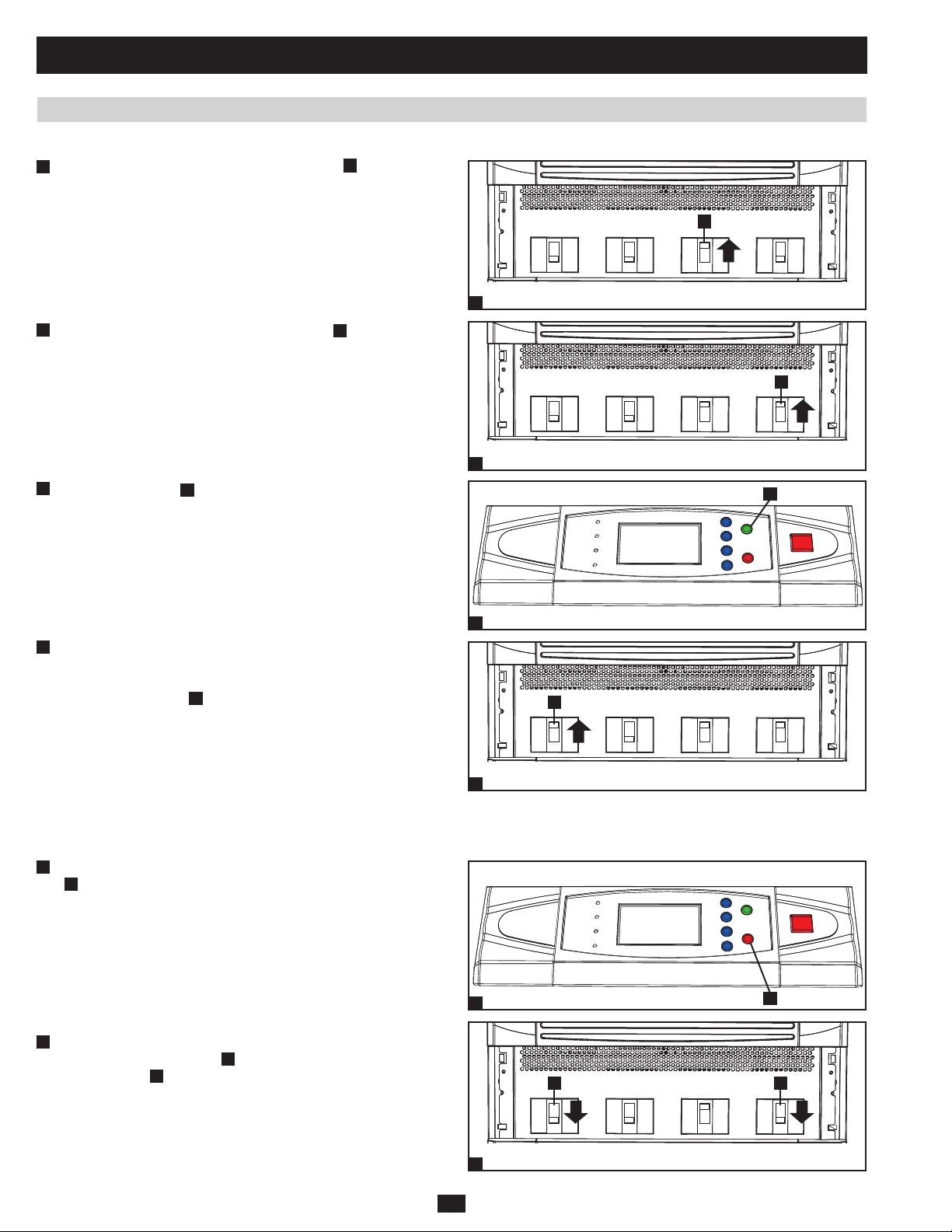
1.6.8 Start-Up Procedure (Parallel UPS) (continued)
Switch on the bypass input circuit breaker switch •
3
UPS system. After a brief initialization process, the LCD screen
will show “ON AUTO BYPASS” and the “BYPASS” LED will
illuminate.
A
of each
A
4
Switch on the main input circuit breaker switch •
A
of each UPS
system.
5
Press the ON button •
A
of one of the UPS systems for 3 seconds
(until you hear a beep), then release the button. The inverter will
activate and synchronize with the bypass source. Press the ON
button for the other UPS system for 3 seconds (until you hear a
beep), then release the button. When the inverter of each UPS
system is operating normally, they will automatically switch from
auto bypass (reserve) mode to online (normal) mode at the same
time. The “BYPASS” LED will darken and the “NORMAL” LED
will illuminate.
6
Check the output voltage of each UPS system. The phase deviation •
PRELIMINARY
between each UPS system should be less than 5V. If the phase
deviation is within the acceptable range, switch on the output
circuit breaker switch
A
of each UPS system. Note: For more
information on checking the output voltage of each UPS system,
see section 10-6 of the owner’s manual.
Output Manual
3
Output Manual
4
5
A
Bypass
Bypass
Bypass
Input
Bypass
Input
Main
Input
Main
Input
A
A
Output Manual
6
Bypass
Bypass
Input
Main
Input
1.6.9 Shutdown Procedure (Parallel UPS)
Warning: The UPS system shutdown procedure will eliminate the AC power output for all loads. Before shutdown, confirm that all loads
are turned off or place the UPS systems in manual bypass mode to keep loads powered by the bypass (reserve) power source.
1
For the UPS system you wish to shut down, press the OFF button •
A
for 3 seconds (until you hear a beep), then release the button.
If the other UPS system can support the connected equipment
loads alone, the UPS system that was turned off will shut down its
inverter and its LCD screen will read “LOAD NOT POWERED”.
The other UPS system’s LCD screen will read “ONLINE MODE”.
If the total connected equipment load is too large to be handled
by a single UPS system, both UPS systems will shut down their
inverters and switch to bypass mode, and their LCD screens will
1
A
read “ON AUTO BYPASS.”
2
For the UPS system you wish to shut down, switch off the main •
input circuit breaker switch
B
breaker switch
.
A
, then switch off the output circuit
22
AB
Output Manual
2
Bypass
Bypass
Input
Main
Input
Page 23
1 Basic Operation (continued)
1.6 Start-Up, Shutdown and Bypass (continued)
1.6.9 Shutdown Procedure (Parallel UPS) (continued)
3
For the UPS system you wish to shut down, switch off the bypass •
input circuit breaker switch A.
A
Output Manual
4
When the UPS system is completely shut down, the LCD screen •
3
Bypass
Bypass
Input
Main
Input
will be completely off. If the UPS systems have external battery
cabinets connected, switch off the external battery cabinet circuit
breaker switch
A
of each battery pack.
A
Note: If the UPS system remains off for an extended period of time, it
should be turned on periodically to allow the batteries to recharge. The
UPS system should be turned on and the batteries should be recharged
at least one uninterrupted 24-hour period every 3 months. Failure
to recharge the batteries periodically may cause irreversible battery
damage.
4
1.6.10 Manual Bypass Procedure (Parallel UPS)
Warning: When the UPS system is in manual bypass, the inverter shuts down. Connected equipment loads are powered by the bypass
(reserve) power source and will not receive battery backup during a utility power failure.
For the first UPS system you wish to shut down, press the OFF •
1
A
button
for 3 seconds (until you hear a beep), then release
the button. If the other UPS system can support the connected
equipment loads alone, the UPS system that was turned off will
shut down its inverter and its LCD screen will read “LOAD NOT
POWERED”. The other UPS system’s LCD screen will read
PRELIMINARY
“ONLINE MODE”. If the total connected equipment load is too
large to be handled by a single UPS system, both UPS systems
will shut down their inverters and switch to bypass mode, and their
1
A
LCD screens will read “ON AUTO BYPASS”. Repeat step 1 for
the second UPS system you wish to shut down.
2
Switch off the main input circuit breaker switch •
system.
A
of each UPS
A
3
Confirm that both UPS systems are shut down, then switch on the •
manual bypass input circuit breaker switch
A
of each UPS system.
The bypass (reserve) power source will power the loads and the
LCD screen will read “ON MANUAL BYPASS.”
4
Switch off the bypass input circuit breaker switch •
circuit breaker switch
B
of each UPS system. The LCD screen
A
and the output
will turn off completely.
23
Output
2
Output
3
Output
4
Manual
Bypass
A
Manual
Bypass
Manual
Bypass
Bypass
Input
Bypass
Input
AB
Bypass
Input
Main
Input
Main
Input
Main
Input
Page 24
1 Basic Operation (continued)
1.6 Start-Up, Shutdown and Bypass (continued)
1.6.10 Manual Bypass Procedure (Parallel UPS) (continued)
5
If the UPS systems have external battery cabinets connected, switch •
off the external battery cabinet circuit breaker switch
battery pack.
6
In this mode, only the output circuit breaker switch •
terminal block B contain hazardous voltage, allowing qualified
service personnel to perform maintenance or repair. Note:
Qualified service personnel may prefer to de-energize the UPS
systems completely, depending on local codes and the nature of the
maintenance or repair.
1.6.11 Switching from Manual Bypass to Normal Mode (Parallel UPS)
1
If the UPS systems have external battery cabinets connected, switch •
off the external battery cabinet circuit breaker switch
battery pack.
A
of each
A
and the
A
of each
5
6
A
B
A
A
PRELIMINARY
2
Switch on the bypass input circuit breaker switch •
circuit breaker switch B of each UPS system.
3
Confirm that both UPS systems are shut down, then switch off the •
manual bypass input circuit breaker switch
The LCD screen will read “ON AUTO BYPASS.”
4
Switch on the main input circuit breaker switch •
system.
5
Press the ON button •
A
of the first UPS systems for 3 seconds
(until you hear a beep), then release the button. Press the ON button
for the second UPS system for 3 seconds (until you hear a beep),
then release the button. When the inverter of each UPS system is
operating normally, they will switch to online (normal) mode at the
same time.
A
and the output
A
of each UPS system.
A
of each UPS
A
1
AB
Output Manual
2
Output
3
Bypass
A
Manual
Bypass
Bypass
Input
Bypass
Input
Main
Input
Main
Input
A
Output
4
Manual
Bypass
Bypass
Input
Main
Input
5
24
Page 25
1 Basic Operation (continued)
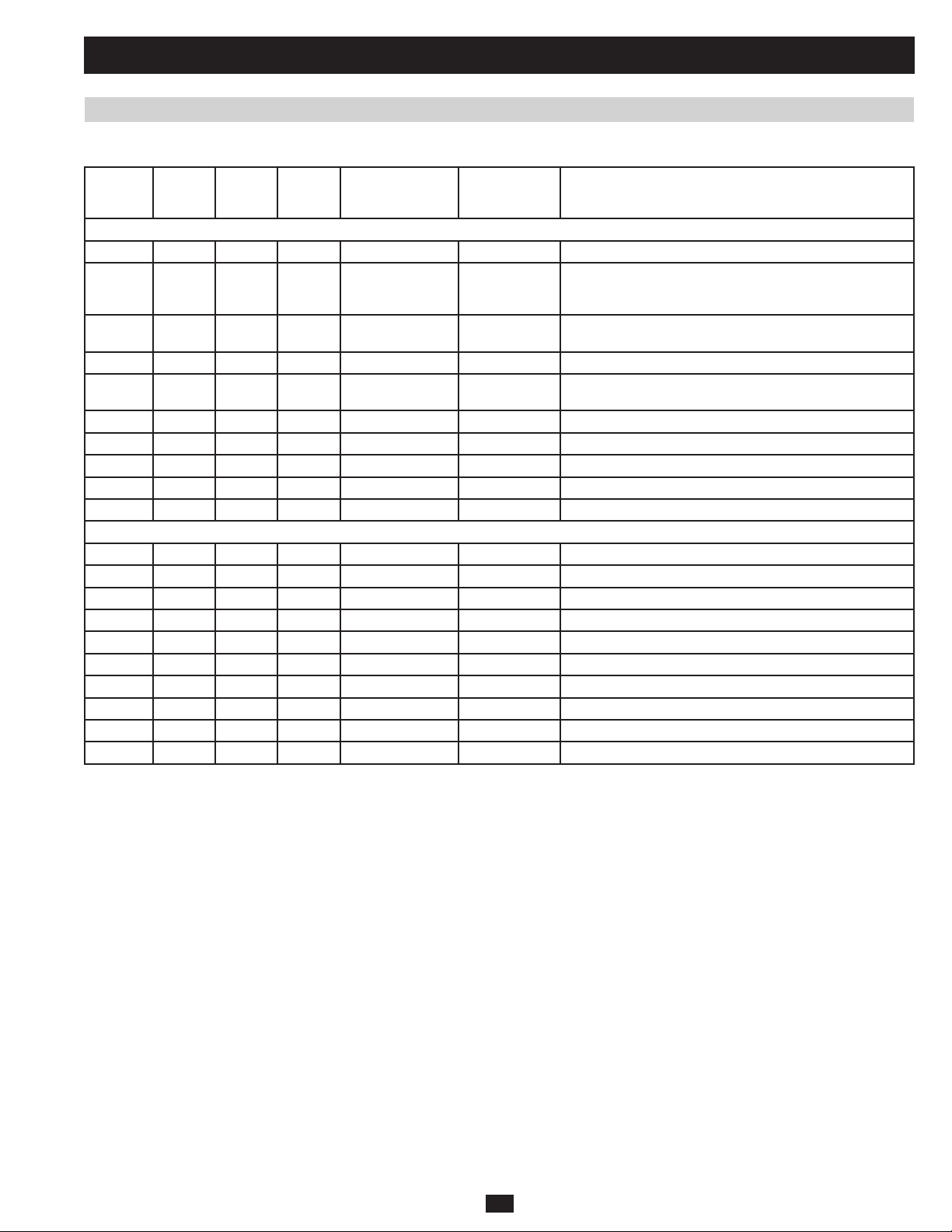
1.7 Printed Circuit Boards (PCB)
Table 1.7a lists the printed circuit boards present in each UPS system:
SU80KX
SU80K
SU80KTV
V (2pcs) V (2pcs) NH-SYS-F1(BYP) 16-5505001371 Input EMI Filter for Bypass
V (2pcs) V (2pcs) NH-SYS-F1(MAIN) 16-5505001371 Input EMI Filter for Main
PRELIMINARY
SU60KX
SU60K
V V V V NH-SYS-LCD 16-5505001323 Circuit for LCM, Circuit for LED and Function Key
V V V V NH-SYS-R 16-5505001327 Circuit for RS232, Output Dry Contact, Parallel Port,
V V V V NH-SYS-X 16-5505001319 Circuit for REPO, Input Dry Contact and Circuit for sense
V V V V NH-SYS-M 16-5505001321 System MCU and Control Circuit
V V V V NH-SYS-P 16-5505001325 Auxiliary Power for System, Detect Circuit for Voltage and
V V V V NH-SYS-B 16-5505001317 EMI Filter for Battery Input
V V V V NH-SYS-LA 16-5505001322 Input EMI Filter for each Power Module
V V V NH-SYS-LB 16-5505001353 Input EMI Filter for each Power Module
V V NH-SYS-LC 16-5505001354 Input EMI Filter for each Power Module
V NH-SYS-LD 16-5505001355 Input EMI Filter for each Power Module
V V NH-SYS-S 16-5505001326 Driver Circuit for Bypass SCR
V V V V NH-SYS-FC 16-5505001349 Output EMI Filter
V V NH-SYS-F2(MAIN) 16-5505001373 Input EMI Filter for Bypass
V V NH-SYS-F2(BYP) 16-5505001374 Input EMI Filter for Main
V V NH-SYS-F3 16-5505001372 Circuit for Surge suppress
V V V V NH-SYS-FB 16-5505001346 Circuit for Bypass Back-feed Detect
SU40KX
SU40K SU20KX PCB name P/N Description
TOP
Connector to connect with each Power Module, Circuit for
2 Slots
External Battery Cabinet Temperature
Current
BOTTOM
V V NH-SYS-SA 16-5505001370 Driver Circuit for Bypass SCR
V (2pcs) V (2pcs) NH-SYS-FA 16-5505001347 Input EMI Filter
Table 1.7a
25
Page 26
1 Basic Operation (continued)
1.7 Printed Circuit Boards (PCB) (continued)
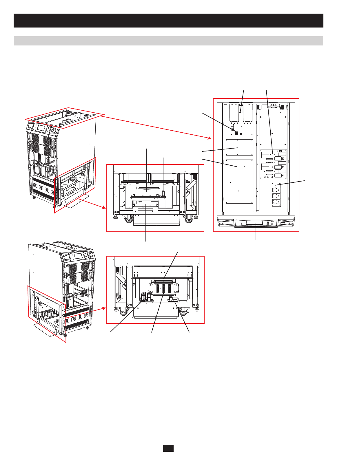
1.7.1 PCB Location (System)
1.7.1.1 KX Models
SU20KX and SU40KX:
FA (BYP)
FB
X LA and LB
R
M
P
B
PRELIMINARY
O/P CT FCBYPASS SCR
FA (MAIN)
SA
LCD
26
Page 27
1 Basic Operation (continued)
1.7 Printed Circuit Boards (PCB) (continued)
1.7.1 PCB Location (System) (continued)
1.7.1.1 KX Models (continued)
SU60KX and SU80KX:
F1 (BYP)
XBLA, LB, LC, LD
R
F3 FB
M
P
PRELIMINARY
LCDF1 (MAIN) F2 (BYP) F2 (MAIN)
O/P CT S
27
PC
Page 28
1 Basic Operation (continued)
1.7 Printed Circuit Boards (PCB) (continued)
1.7.1 PCB Location (System) (continued)
1.7.1.2 K Models
SU40K:
X LA, LB
R
M
FA (BYP) FA (MAIN)
O/P
PRELIMINARY
Transfer
I/P
Transfer
SA
Bypas SCR FC
FB
B
P
LCD
O/P CT
28
Page 29
1 Basic Operation (continued)
1.7 Printed Circuit Boards (PCB) (continued)
1.7.1 PCB Location (System) (continued)
1.7.1.2 K Models (continued)
SU60K:
X LA, LB, LC
R
M
P
F1 (BYP)
PRELIMINARY
I/P Tx
F1 (MAIN)
O/P Tx
Bypas SCR S
F3
F2 (BYP)
FB
F2 (MAIN)
BLCD
O/P CT FC
29
Page 30
1 Basic Operation (continued)
1.7 Printed Circuit Boards (PCB) (continued)
1.7.1 PCB Location (System) (continued)
1.7.1.2 K Models (continued)
SU80K:
LA, LB, LC, LD
X
R
M
FBF2F1(BYP)
P
B
O/P Tx
PRELIMINARY
I/P Tx
F1(MAIN)
O/P CT FC
F2(BYP) F2(MAIN)
Bypass SCR S
LCD
30
Page 31
1 Basic Operation (continued)
1.7 Printed Circuit Boards (PCB) (continued)
1.7.2 PCB Location (Power Module)
PCB Board Name Description
NH-PM-A Rectifi er of Phase R and S, Inductance and Switching Devices of DC-DC Converter, Bus Capacitors and Battery SCR
NH-PM-K Rectifi er of Phase T and S, Inductance and Switching Devices of DC-DC Converter, Bus Capacitors and Battery SCR
NH-PM-C Charger
NH-PM-P Auxiliary Power
NH-PM-M Control Circuit for PFC and Charger
NH-PM-DSP(PFC) DSP Chip (Assemble on NH-PM-M Board)
NH-PM-B Switching Devices of Inverter (Phase T) and Bus Capacitors
NH-PM-D Switching Devices of Inverter (Phase R and S) and Bus Capacitors
NH-PM-L LC Filter of Inverter, Current Sensor and Static Switch Circuit of Inver ter
NH-PM-N Control Circuit for Inverter
NH-PM-DSP(INV) DSP Chip (Assemble on NH-PM-N Board)
NH-PM-H1 External Connector of Power Module AC Input
NH-PM-H2 External Connector of Power Module Battery Input
NH-PM-H3 External Connector of Power Module AC Output
circuit
circuit
H3
N
H2
PRELIMINARY
L
P
Fig 1.7.2a
D
B
H1
K
Fig 1.7.2b
33
A
M
C
Page 32

1 Basic Operation (continued)
1.8 Block and Wiring Diagrams (continued)
1.8.1 KX Models
Input: 3-phase 4-wire 230/380Vac
Output: 3-phase 4-wire 230/380Vac
The SU20KX (Figure 1.8.1a) has a model rating of 20kVA UPS and contains one power module and 40 internal batteries (which can be increased to
80, if necessary). (See Figure 1.8.1b for wiring.)
Q3
Manual Bypass
Circuit Breaker
Manual Input
Q5
Bypass Input
20kVA/3U POWER MODULE
EMPTY
12V, 9AH, 10PCS
12V, 9AH, 10PCS 12V, 9AH, 10PCS
EMPTY EMPTY
EMPTY EMPTY
12V, 9AH, 10PCS
STS
Q4
Output
Circuit Breaker
MAIN
INPUT
EXTERNAL
BATTERY
Q2
Bypass Input
Circuit Breaker
Main
Q1 LOAD
Main Input
Circuit Breaker
Fig 1.8.1a SU20KX Block Diagram
The SU40KX (Figure 1.8.1c) has a model rating of 40kVA UPS and contains two power modules and 80 internal batteries.
(See Figure 1.8.1d for wiring.)
PRELIMINARY
Q3
Manual Bypass
MAIN
INPUT
EXTERNAL
BATTERY
Circuit Breaker
Q2
Bypass Input
Circuit Breaker
Main
Q1
Main Input
Circuit Breaker
Q5
Manual Input
Bypass Input
STS
20kVA/3U POWER MODULE
20kVA/3U POWER MODULE
12V, 9AH, 10PCS
12V, 9AH, 10PCS 12V, 9AH, 10PCS
12V, 9AH, 10PCS 12V, 9AH, 10PCS
12V, 9AH, 10PCS 12V, 9AH, 10PCS
12V, 9AH, 10PCS
Q4
Output
Circuit Breaker
LOAD
Fig 1.8.1c SU40KX Block Diagram
34
Page 33

2 Theory of Operation (continued)
2.2 DC Auxiliary Power Circuit (continued)
Located at NH-SYS-M board (System MCU and Control Circuit)
RM42
5VS
K- ON
(a) The input of DC auxiliary power circuit is from positive battery.
(b) MCU detects the “on” key (on LCD board) status through KEY-ON(21)
(c) When AC auxiliary power circuit is activated and battery is present, AUXON (64) is high and DC auxiliary power circuit will be on.
(d) If AUXOFF (44) is high during backup mode, DC auxiliary power will be off.
G1
RM43
CM24
KEY_ON
(21)
AUXON
(64)
AUXOFF
(44)
RM22
AUX- ON
RM26
AUX- OFF
2.3 Auxiliary Power Failure Detection
Located at NH-SYS-P board (Auxiliary Power for System, Detect Circuit for Voltage and Current)
DP11
QP8
AUX-FAI L
+12VB
RP 18
+12VS
ZDP5
RP 20
RP 19
G1
PRELIMINARY
+12VP
Located at NH-SYS-M board (System MCU and Control Circuit)
RP 21
+12VS
RP 23
ZDP6
RP 22
DP12
QP10
QP9
G1
RP 24
G1
RM34
G1
RM35
CM23
AUXFAIL
(71)
5VS
AUX- FAI L
+12VP is from AC auxiliary power and +12VB is from DC auxiliary power. During AC mode, +12VP and +12VB should both be live. If one or
both of them fails, MCU can detect auxiliary power failure through AUXFAIL (71) (low active).
51
Page 34

2 Theory of Operation (continued)
2.4 Output Current Detection
Located at NH-SYS-P board (Auxiliary Power for System, Detect Circuit for Voltage and Current)
CP 25
RP119
RP120
RP124
RP130
RP135
RP140
RP146
RP147
RP155
RP158
(W18)
(W19)
(W20)
CNP 1 1
1
2
CNP 1 2
1
2
CNP 1 3
1
2
OPCT_R+
OPCT_R-
OPCT_S+
OPCT_S-
OPCT_T+
OPCT_T-
OPCT_R-
RP 12 1 RP122
RP 12 5
OPCT_R+
OPCT_S-
RP 13 7 RP138
RP 14 1
OPCT_S+
OPCT_T-
RP 15 0 RP151
RP 15 6
OPCT_T+
PRELIMINARY
CP 89
CP 92
CP 94
G1
G1
G1
-12VS
RP126
RP142
RP157
2
3
411
CP 91
RP136
9
10
CP 93
RP148
13
12
CP 26
UP19 A
CP 90
UP19 C
UP19 D
G1
1
IoutR
G1+12VS
8
IoutS
14
IoutT
Located at NH-SYS-M board (System MCU and Control Circuit)
5VS
RM25
IoutR IoutS I outT
RM33
DM3
3
Iout_R Iout_TIout_S
(101)
CM22
12
G1
RM44
RM47
5VS
G1
3
CM25
12
DM7
(103)
RM61
5VS
RM58
DM13
3
(90)
CM30
12
G1
(a) Connectors CNP11, CNP12 and CNP13 connect to 3 Output CT individually.
(b) MCU detects 3-phase output currents through Iout_R (101), Iout_S (103) and Iout_T (90). The output current could be bypass current or in-
verter current, depending on the operation mode.
52
Page 35

2 Theory of Operation (continued)
2.5 Input Voltage Detection
Located at NH-SYS-P board (Auxiliary Power for System, Detect Circuit for Voltage and Current)
CP8 3
RP1 6 0
UP20B
6
5
9
10
13
12
UP20C
UP20D
CP8 7
RP1 7 6
CP8 8
RP1 8 4
7
VinR
8
VinS
14
VinT
CNP 7
CNP 8
CP7 8
RP159
RP1 6 5RP 1 6 4
RP162RP 161
BYP / R
IP/R
IP/S
IP/T
IP/N
BYP / S
BYP / T
BYP / R
BYP / N
BYP / N
BYP / S
BYP / T
1
2
3
4
5
6
7
1
2
3
4
5
6
7
RP163
RP168RP 167 RP169
RP178RP 177
RP186RP 185
RP173
RP179
RP187
CP9 5
G1
UP18B
6
5
9
10
13
12
UP18C
UP18D
7
CP8 1
RP175
8
CP8 2
RP183
14
Vby pR
Vby pS
Vby pT
IP/R
IP/N
IP/S
IP/T
RP1 6 6
RP1 7 1RP 1 7 0 RP1 72
RP1 8 1RP 1 8 0
RP1 8 2
RP1 8 9RP 1 8 8
RP1 9 0
RP1 7 4
CP8 6
G1
Located at NH-SYS-M board (System MCU and Control Circuit)
5VS
Vby pR
5VS
DM1
RM27
RM23
RM30
5VS
DM2
RM28
VinR
BYP Z O_ R INPZO_R
(12)
QM1
PRELIMINARY
RM36
RM40
DM5
3
Vbyp_R
(89)
RM38
G1
CM20
RM37
RM41
DM6
Vin _R
3
Vin_R
(92)
5VS
RM24
RM31
(14)
QM2
CM21
RM39
G1
Vby pS
RM50
RM54
12
G1
5VS
DM9
3
12
Vbyp_S
(91)
G1
RM63
Vby pT
RM67
5VS
DM16
3
(93)
12
G1
Vbyp_T
VinS
RM53
RM51
12
G1
5VS
DM11
3
12
Vin_S
(94)
G1
(a) MCU detects RMS value of bypass 3-phase voltage via Vbyp_R (89), Vbyp_S (91) and Vbyp_T (93).
(b) MCU detects RMS value of main input 3-phase voltage via Vin_R (92), Vin_S (94) and Vin_T (96).
(c) MCU detects the bypass frequency and zero crossing via BYPZO_R (12) at falling edge.
(d) MCU detects the main input frequency and zero crossing via INPZO_R (14) at falling edge.
VinT
RM64
RM68
5VS
DM17
3
12
Vin_T
(96)
G1
53
Page 36

2 Theory of Operation (continued)
2.6 Output Voltage Detection
Located at NH-SYS-P board (Auxiliary Power for System, Detect Circuit for Voltage and Current)
CP 7 3
RP 1 23
OP/ R
OP/ N
OP/ R
CNP 9
1
2
3
OP/ S
4
5
OP/ T
6
7
OP/ N
Located at NH-SYS-M board (System MCU and Control Circuit)
PRELIMINARY
5VS
OP/ S
OP/ T
RP128RP127
RP132RP131 RP 1 3 3
RP144RP143
RP153RP152
RP 1 29
RP 1 45
RP 1 54
5VS
RP 1 34
UP17 B
6
5
CP 7 2
G1
9
10
13
12
CP 7 6
RP 1 39
UP17 C
CP 7 7
RP 1 49
UP17 D
7
VoutR
8
VoutS
14
VoutT
5VS
VoutR
RM29
RM32
DM4
3
12
Vout_ R Vout_TVout_S
(95)
G1
VoutS
RM45
RM46
DM8
3
(97)
12
G1
VoutT
(a) MCU detects RMS value of 3-phase output voltage via Vout_R (95), Vout_S (97) and Vout_T (99).
RM59
RM60
DM14
3
(99)
12
G1
54
Page 37

2 Theory of Operation (continued)
2.7 Battery Voltage Detection
Located at NH-SYS-P board (Auxiliary Power for System, Detect Circuit for Voltage and Current)
CP 5 7
RP 9 0
G1
UP 10 A
CP 8 0
G1
RP 1 06
UP 10 B
CP 7 9
1
7
Vbatt+
Vbatt-
BAT +
BAT -
RP 9 5RP 94
RP100RP 9 9 RP 1 0 1
RP109RP108
RP115RP114 RP 1 16
RP 9 6
RP 1 10
RP118
RP102
G1
G1
CP 5 8
CP 6 0
-12VS
2
3
84
+12VS
CP 5 9
6
5
PRELIMINARY
Located at NH-SYS-M board (System MCU and Control Circuit)
Vba tt+
RM49
CM28RM5 5
5VS
DM1 0
3
Vba tt_+
(98)
RM70
Vba tt-
RM62
CM32
5VS
DM1 5
3
Vba tt_-
(100)
12
G1
(a) MCU detects battery voltage via Vbatt_+ (98) and Vbatt_- (100).
12
G1
55
Page 38

2 Theory of Operation (continued)
2.8 Bypass SCR Short-Circuit Detection
Located at NH-SYS-FB board (Circuit for Bypass Back-Feed Detect)
CFB18
SCCT_ S+
CFB19
SCCT_ T+
CFB20
RFB1
RFB2
RFB7
RFB3
RFB4
RFB8
RFB5
RFB6
RFB9
BKFD_ R
BKFD_ S
BKFD_ T
CTFB1
SCCT_R+
CTFB2
CTFB3
R
CFA22
S
CFA18
CNFB13
1
2
3
4
T
CFA12
N
DFB1
DFB2
DFB3
BKFD_ R
QFB1
BKFD_ S
QFB2
BKFD_ T
QFB3
Located at NH-SYS-P board (Auxiliary Power for System, Detect Circuit for Voltage and Current)
+12VS
RP3 4 RP 3 3
PRELIMINARY
BKFD_ R
+12VS
RP8 8
BKFD_ S
+12VS
RP104
BKFD_ T
CP6 2
RP8 7
CP6 7
RP103
CP7 0
-12VS
RP8 6
-12VS
+12VS
RP9 8
-12VS
+12VS
RP117
CP6 3
G1
UP18A
2
3
411
CP6 4
UP20A
2
3
411
CP8 5
UP17A
2
3
411
CP7 5
DP13
DP15
DP46
RP3 8
RP9 3
RP112
RP3 5
RP3 7
CP6 5
G1
RP8 9
RP9 2
CP6 8
G1
RP1 0 5
RP1 1 1
CP7 1
1
G1+12VS
CP8 4
G1
1
G1
CP7 4
G1
1
G1
SCRST_R
QP13
SCRST_S
QP15
SCRST_T
QP17
G1
Located at NH-SYS-M board (System MCU and Control Circuit)
RM48
5VS
SCRST_R
RM52
STSho r t _R STSho r t _ S ST Sh or t _ T
(5)
CM26
G1
RM56
5VS
SCRST_S
RM57
(129)
CM29
G1
RM65
5VS
SCRST_T
RM66
(128)
CM33
G1
(a) During backup mode, bypass 3 SCRs should be off and zero current should be running through CTFB1, CTFB2 and CTFB3. If current is
running through CTFB1, CTFB2 or CTFB3, then STShort_R (5), STShort_S (129) or STShort_T (128) will be low. The UPS will turn off its
inverter to prevent back-feed voltage.
56
Page 39

2 Theory of Operation (continued)
2.9 Bypass SCR Driver
Located at NH-SYS-S or NH-SYS-SA board (Driver Circuit for Bypass SCR)
CSA1
+12VS
BYP ST S1
RSA1
+12VS+12VS
RSA3
RSA6
QSA4QSA7
RSA2
G1
G1
+12VS
RSA4
RSA8
QSA5
G1
+12VS
RSA5
RSA10
QSA6
G1
RSA7
RSA9
RSA11
G1
QSA1
G
G1
QSA2
G
G1
QSA3
G
G1
CSA5
D
RSA12
S
CSA2
+12VS
G1
CSA7
D
RSA13
S
CSA3
+12VS
G1
CSA9
D
RSA14
S
Located at NH-SYS-M board (System MCU and Control Circuit)
(1)
5VS
BYP STS
DM19
RM78
RM82
CM50
BYP STS2
Q
DIS
CM53
G1
RM75
5VS
RM91
3
7
6
RM103
TOBYP-J
DM28 DM2 9
#TOBYP_O
DM21
DM22
RM83
QM4
RM93
RM92
RM96
G1
RM102
TOBYP_O
(47)
QM6
#TOBYP_I
RM141
TOBYP_I
(131)
BYPASS Static Transfer Switch Control CKT.
8
UM6C
5VS
RM99
9
CM54
G1 5VS
CM122
5VS
14
1
+
3
UM6A
-
2
7
G1
BYP STS2
RM101
TOBYP-J
PRELIMINARY
(70)
CENT RAL _ OK
UM9
4
2
CM52
DM27
G1
8
R
VCC
TRIG
GND
CVol t5THR
1
G1
CSA4
CSA6
CSA8
10
G1
DSA1
DSA4
DSA7
#TOBYP_O
CM92
G1
CM97
G1
5
6
RM98
TSA 1
2
3
4
2803402000
TSA 2
2
3
4
2803402000
TSA 3
2
3
4
2803402000
#TOBYP_I
UM6B
DM26
12
UM6D
13
DSA2
6
7
9
10
6
7
9
10
6
7
9
10
4
RSA15
CSA10
DSA3
RSA16
CSA11
DSA5
RSA17
CSA12
DSA6
RSA18
CSA13
DSA8
RSA19
CSA14
DSA9
RSA20
CSA15
DM25
DM30
DM31
11
DM39
RM97
RM90
QM8
FAN_ON
RM94
RM2
CM51
CNSA1
6
5
4
3
2
1
CNSA2
6
5
4
3
2
1
CNSA3
6
5
4
3
2
1
+12VS
G1
RM100
G1
G2
K2
K1
G1
G2
K2
K1
G1
G2
K2
K1
G1
RM95
BYP STS1
QM7
Located at NH-SYS-R board (Circuit for RS232, Output Dry Contact, Parallel Port, Connector to connect with each Power Module, Circuit for 2 Slots)
G1
#TOBYP_O
#TOBYP_I
5VS
5VS
CR8
RR1
5VS
14
1 2
7
G1
RR8
CR10
UR4A
G1
UR3
1
2
+12VSF
UR6
4
3
RR2
QR1
VS TOBYP
CR4
4
3
RR6
G4
DR16
RR9
ZR1
CR7
RR10
1
2
CR9
57
Page 40

2 Theory of Operation (continued)
K
2.9 Bypass SCR Driver (continued)
(a) The bypass SCR driver signal “BYPSTS1” is controlled by MCU or “TOBYP_J” according to the signal “CENTRAL_OK.”
(b) “CENTRAL_OK” is the output of MCU watchdog. If MCU is operating normally, “CENTRAL_OK” will be high and the bypass SCR driver
signal will be controlled by “BYPSTS” (1) (high active). If MCU is not operating normally, “CENTRAL_OK” will be low and the bypass SCR
driver signal will be controlled by “TOBYP_J” (high active).
(c) UM9 is a 45 kHz self-oscillator that can provide pulse signal for driver bypass SCR.
(d) The “TOBYP_J” signal is limited by “#TOBYP_I.”
2.10 Watchdog for System MCU
Located at NH-SYS-M board (System MCU and Control Circuit)
5VS
LEDM1
G1
RM72
Q
DIS
THR
UM3
TLC555C
CM46
RM89
LED(GRN)
RM1
3
7
6
RM88
CENT RA L_ O
(70)
5VS
5VS
CM36
QM5
G1
4
2
5
CM45
R
TRIG
CVo l t
8
VCC
GND
1
RM71
1
2
CNM2
2.5X2P
CM39
RM81
RM86
QM3
DM24
G1
SYS_RD Y
(4)
PRELIMINARY
(a) SYS_RDY (4) will send out a pulse to reset CM46. CM46 will then be recharged by 5V through RM88. “CENTRAL_OK” will maintain a high
level. If SYS_RDY (4) does not send out a pulse during a specifi c period (for example, during an MCU crash), then “CENTRAL_OK” will be
low.
(b) Test JUMP (CNM2): If CNM2 is shorted, then “CENTRAL_OK” will be low. If CNM2 is opened, “CENTRAL_OK” will stay high during
normal operation.
58
Page 41

2 Theory of Operation (continued)
2.11 LCD Panel Control Circuit
Located at NH-SYS-M board (System MCU and Control Circuit)
TO LCD
CNM5
RM127
RM135
RM143
RM149
RM154
1 2
3 4
5 6
7 8
9 10
11 12
13 14
15 16
17 18
19 20
21 22
23 24
25 26
27 28
29 30
KEY_ESC
(8)
KEY_DOWN
(9)
KEY_OFF
(22)
KEY_UP
(10)
KEY_ENT
(7)
G1
(2)
(70)
U-Lc mCA
(62)
(73)
(74)
(75)
(76)
(77)
(78)
VLED
G1
U-Lc mBL
G1
U-LED0
U-LED1
U-LED2
U-LED3
U-LED4
U-LED5
CENT RAL _ OK
+12VS
5VS
RM15 5
G1
LcdD1
LcdD3
LcdD5
LcdD7
UM5
8
COM
GND
7B77C
6B66C
5B55C
4B44C
3B33C
2B22C
1B11C
RM134
RM137
QM9
RM13 9
G1
RM144
RM14 8
NO+
CM104
G1
+12VS G1
4 11
CM11 3
2
1
3
G1
UM7A
LM324AD
CM112
(33)
(35)
(37)
(39)
9
10
11
12
13
14
15
16
LED0
LED1
LED2
LED3
LED4
LED5
BYP _ OK
BKLI T
(50)
(49)
(63)
RM13 8
G1
CM12 1
EPO
(85)
1
CONT RAST
VLED
LED0 LED1
LED2 LED3
LED4 LED5
OFF ENT
ESC UP
DOWN BKLI T
NO+ G1
CONTRAST Lc dDATA
LcdD0
(32)
LcdD2
(34)
LcdD4
(36)
LcdD6
(38)
LcdWR LcdCS
G1
CM75CM74CM73CM72 CM79CM78CM77CM76
RM126
ESC
KEY_ESC
CM85
G1
RM133
DOWN
KEY_DOWN
CM91
G1
RM140
OFF
KEY_OFF
CM96
G1
RM147
RM152
KEY_UP
CM103
G1
KEY_ENT
UP
PRELIMINARY
ENT
CM110
G1
St and- A l one
NORMAL LED
LED0
BYPA SS LED
LED1
FAULT LED
LED2
BATTERY L ED
LED3
NC
LED4
NC
LED5
G1
G1
G1
RM11 6
ZDM1
RM12 1
ZDM2
RM132
ZDM3
LcdDATA
LcdCS
LcdWR
HSM1
1
U-Lc dDATA
CM67
U-Lc dCS
CM80
U-Lc dWR
CM90
HS
+12VS
RM158
UM10
1
Vin
+5V
CM11 8 CM119
GND
2
G1
3
CM120
VLED
(a) MCU detects the status of EPO button (on LCD display panel) via “EPO” (85) (low active). When the EPO button is activated, UPS will shut
down the output and turn off the inverter. When the EPO button is released, UPS will stay in bypass mode.
(b) MCU can control the LCD backlight via “U-lcmBL” (62).
(c) MCU can adjust the contrast of LCD by PWM control via “U-lcmCA” (2).
59
Page 42
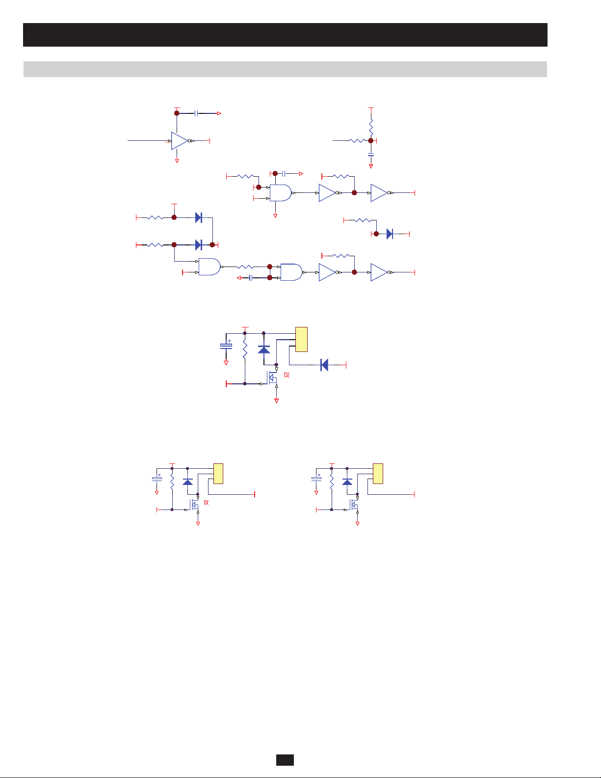
2 Theory of Operation (continued)
2.12 Fan Control Circuit
Located on NH-SYS-M board (System MCU and Control Circuit)
+12VS
CM123
G1
9 8
FAN- C
(17)
RM163
5VS
RM166
5VS
Located on NH-SYS-P board (Auxiliary Power for System, Detect Circuit for Voltage and Current)
UM8A
1 16
G1
FANLOCK_A
FAN_ ON
(19)
DM34
5
6
FAN- SP E ED - C
UM12B
4081
5VS
(143)
DM32
FAN_ LOCK _A
4
G1
RM16 1
FAN_ A
FAN_ ON
RM168
CM127
5VS
14
1
2
7
+
-
CM12 4
UM12A
4081
G1
8
9
UM12C
4081
3
G1
+12VS
4 13
+12VS
6 11
10
(18)
RM6
10K
RM162
5 12
UM8D
ULN2003A
RM164
5VS
FANLOCK_B FAN _L OCK_ B
(48)
RM167
UM8F
ULN2003A
7 10
5VS
G1
RM7
10K
CM13 6
104
FANLOCK_C
UM8E
FAN_SPEED_A
ULN2003A
DM33
UM8G
FAN_SPEED_B
ULN2003A
DP5
+12VS
CP 96
FAN_ SP EE D_ C
RP194
G1
G
PRELIMINARY
CNP 1 6
1
2
3
D
QP14
S
G1
FANLOCK_C
DP6
Located on NH-SYS-S or NH-SYS-SA board (Driver Circuit for Bypass SCR)
TO FAN
CSA16
FAN_SP EE D_ A
DSA10
+12VS
RSA21
G1
G
CNSA4
1
2
3
D
QSA9
S
G1
FAN_LOCK_A
CSA17
G1
FAN_SPEED_B
+12VS
RSA22
DSA11
CNSA5
1
2
3
D
QSA8
G
S
G1
FAN_L OCK _B
(a) Fan C is located at the rear panel of the power module’s input EMI fi lter. Fan A and Fan B are both located at the heat-sink for bypass SCR.
(b) MCU controls fan C via FAN-C (17).
(c) MCU detects a fan C failure via (18).
(d) When in bypass mode, FAN_A (143) will be high to control fan A; fan B will be off. If fan A experiences a failure, fan B will turn on.
(e) MCU detects a fan A failure via FANLOCK_A (19).
(f) MCU detects a fan B failure via FANLOCK_B (48).
60
Page 43

2 Theory of Operation (continued)
2.13 Bypass SCR Temperature Detection
Located on NH-SYS-M board (System MCU and Control Circuit)
5VREF
G1
RM77
6
5
CM49
4 11
RM79
+12VS
2
G1
UM7B
5VS
DM23
7
RM84
CM48
3
12
G1
HS_TEMP
(105)
RM76
STS_ TH-
RM87
Located on NH-SYS-S or NH-SYS-SA board (Driver Circuit for Bypass SCR)
CNSA 6
1
2
5VREF
STS_ TH -
CON2(2. 54)
(a) Temperature sensor (NTC) is screwed onto the heat-sink of bypass SCR and connected to CNSA6 on the NH-SYS-S or SA board.
(b) MCU detects the temperature via HS_TEMP (105).
2.14 Communication Circuit for RS232
PRELIMINARY
Located on NH-SYS-R board (Circuit for RS232, Output Dry Contact, Parallel Port, Connector to connect with each Power Module, Circuit for 2
Slots)
#TX_232
5VS
#RX_232
RR33
5VS
RR37
RR43
RR26
QR4
G
G1
1 4
2
3
D
S
CR27
G1 5VS
6
5
G1
8
UR15
8
7
7
UR20
CR21
G4+12VSF
232_RX
RR31
6
5
RR11 8
RR38
1 4
2
3
D
QR5
S
G4
-12VSF
G
RR44
RR47
+12VSF
+12VSF
232_TX
232_TX
232_RX
5
9
G4
4
8
3
7
2
6
1
CNR6
RS232 Port
Located on NH-SYS-M board (System MCU and Control Circuit)
(23)
TX_232
RM107
#TX_232
CM58
G1
(24)
RX_232
RM111
#RX_232
CM62
(a) System MCU TX_232 (23) transmits data via RS232 port.
(b) System MCU RX_232 (24) receives data via RS232 port.
G1
61
Page 44

2 Theory of Operation (continued)
2.15 Communication Circuit for Slots
#TX_232
RR33
5VS
#RX_232
5VS
RR37
RR43
RR26
QR4
G
1 4
UR15
2
3
D
S
CR27
G1 5VS
8
7
G1
6
5
G1
8
7
UR20
CR21
G4+12VSF
232_RX
RR31
6
5
-12VSF
RR118
RR38
1 4
2
3
D
QR5
G
S
+12VSF
+12VSF
232_TX
RR44
RR47
232_TX
232_RX
5
9
G4
4
8
3
7
2
6
1
CNR6
RS232 Port
G4
Located on NH-SYS-R board (Circuit for RS232, Output Dry Contact, Parallel Port, Connector to connect with each Power Module,
Circuit for 2 Slots)
RR51
5VS
#TX_Slot1
RR58
RR65
RR67
5VS
PRELIMINARY
#RX_Sl ot1
QR6
G
G1
1 4
UR25
2
3
D
S
CR42
G1 5VS
8
7
6
5
G1
CR36
G4+12VSF
QR8
6
5
2
3
D
S
SLOT1_RX
RR55
-12VSF
RR12 1
RR66
G
+12VSF
+12VSF
SLOT1_TX
RR69
RR73
SLOT 1_ TX
G4
To Slot 1
CNR2
1 2
3 4
5 6
7 8
9 10
+12VSF
CR3
SLOT 1_ RX
CR5
G4
8
7
1 4
UR29
G4
CR52
G4+12VSF
SLOT2_RX
RR77
6
5
RR12 3
RR85
1 4
2
3
D
QR10
S
G4
-12VSF
G
+12VSF
SLOT 2_ TX
+12VSF
SLOT2_TX
RR93
RR95
#TX_Slot2
5VS
#RX_Sl ot2
RR80
5VS
RR84
RR76
QR9
G
RR87
1 4
UR34
2
3
D
S
CR59
G1 5VS
8
7
G1
6
5
G1
8
7
UR38
Located on NH-SYS-M board (System MCU and Control Circuit)
(117)
TX_Slot1
RM115
#TX_Slot1
(122)
TX_Slot2
CM66
G1
(118)
RX_Slot1
RM120
#RX_Slot 1
(121)
RX_ Sl o t 2
CM71
G1
(a) System MCU communicates with Slot 1 via TX_Slot1 (117) and RX_Slot1 (118).
(b) System MCU communicates with Slot2 via TX_Slot2 (122) and RX_Slot2 (121).
G4
RM12 5
RM13 1
To Slot 2
CNR7
1 2
3 4
5 6
7 8
9 10
#TX_Slot2
CM84
G1
#RX_Slot 2
CM89
G1
+12VSF
CR11
SLOT 2_ RX
CR13
G4
62
Page 45
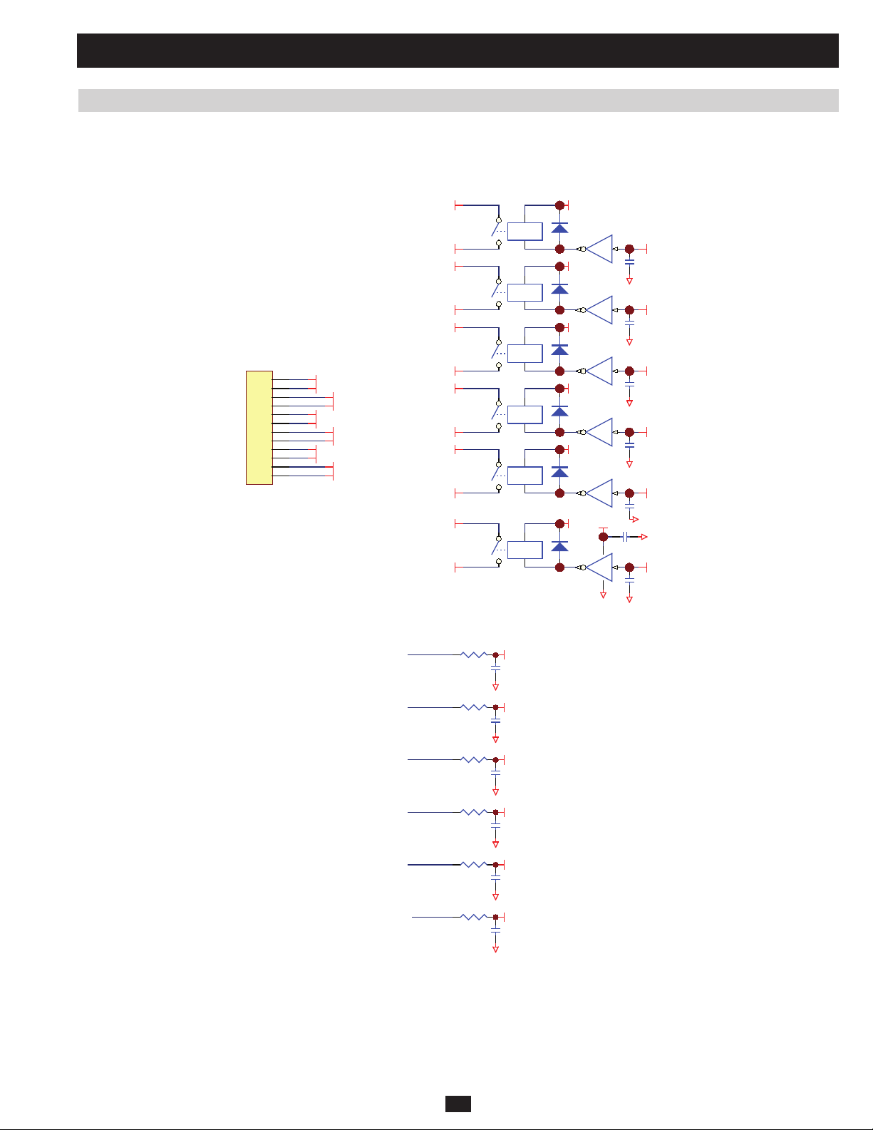
2 Theory of Operation (continued)
2.16 Communication Circuit for Output Dry Contact
Located on NH-SYS-R board (Circuit for RS232, Output Dry Contact, Parallel Port, Connector to connect with each Power Module,
Circuit for 2 Slots)
OUTPUT DRY CONTACT
+12VS
DR1
+12VS
DR3
+12VS
DR4
+12VS
DR6
+12VS
DR8
+12VS
DR10
UR13F
611
DRYA
CR24
UR13E
G1
512
DRYB
CR28
UR13D
G1
413
DRYC
CR33
UR13C
G1
314
DRYD
CR40
UR13B
G1
215
DRYE
CR44
+12VS
9 8
G1
G1
UR13A
CR87
116
DRYF
CR49
G1
G1
M4
CNR8
COMM_A
OP_DRYA
COMM_B
OP_DRYB
COMM_C
1
2
3
4
5
6
7
8
9
10
11
12
OP_DRYA
COMM_ A
OP_DRYB
COMM_ B
OP_DRYC
COMM_ C
OP_DRYD
COMM_ D
OP_DRYE
COMM_ E
OP_DRYF
COMM_ F
OP_DRYC
COMM_D
OP_DRYD
COMM_E
OP_DRYE
COMM_ F
OP_DRYF
RLR1
RLR2
RLR3
RLR4
RLR5
RLR6
3 4
1 2
3 4
1 2
3 4
1 2
3 4
1 2
3 4
1 2
3 4
1 2
PRELIMINARY
Located on NH-SYS-M board (System MCU and Control Circuit)
DRY_F
(84)
DRY_E
(83)
DRY_D
(68)
DRY_C
(67)
DRY_B
(66)
DRY_A
(65)
(a) System MCU sends out dry contact signal to the relays via DRY_A (65), DRY_B (66), DRY_C (67), DRY_D (68), DRY_E (83) and DRY_F
(84).
RM104
200
RM108
200
RM112
200
RM117
200
RM122
200
RM128
200
G1
G1
G1
G1
G1
G1
DRYF
CM55
103
DRYE
CM59
103
DRYD
CM63
103
DRYC
CM68
103
DRYB
CM81
103
DRYA
CM86
103
63
Page 46

2 Theory of Operation (continued)
2.17 Communication Circuit for Input Dry Contact and REPO
Located on NH-SYS-R board (Circuit for RS232, Output Dry Contact, Parallel Port, Connector to connect with each Power Module,
Circuit for 2 Slots)
RX25
RX28
1
2
G4
REP O
M2
CNX4
1
2
+12VSF
REP O
5VS
#R_EPO
RX26
CX14
REPO
UX11
4
3
G1
M3
CNX5
1
2
3
4
+12VSF
IP_DRYA
+12VSF
IP_DRYB
5VS
DRY1
5VS
DRY2
INPUT DRY CONTACT
RX35
UX12
4
CX17
3
G1
RX44
UX13
4
CX22
3
G1
RX34
RX37
1
2
G4
RX42
RX45
1
2
G4
IP_DRYB
Located on NH-SYS-M board (System MCU and Control Circuit)
(86)
R_E P O
RM11 8
#R_EPO
CM69
G1
(79)
DRY_1
RM12 3
DRY1
CM82
G1
DRY_2
PRELIMINARY
(80)
RM12 9
DRY2
CM87
G1
(a) System MCU will detect input dry contact via DRY_1 (79) and DRY_2 (80)
(b) REPO (Remote Emergency Power Off) can be detected via R_EPO (86) by system MCU (high active).
(c) When REPO has activated, System MCU will shut down the output. After the REPO release, the unit will stay in bypass mode.
64
Page 47
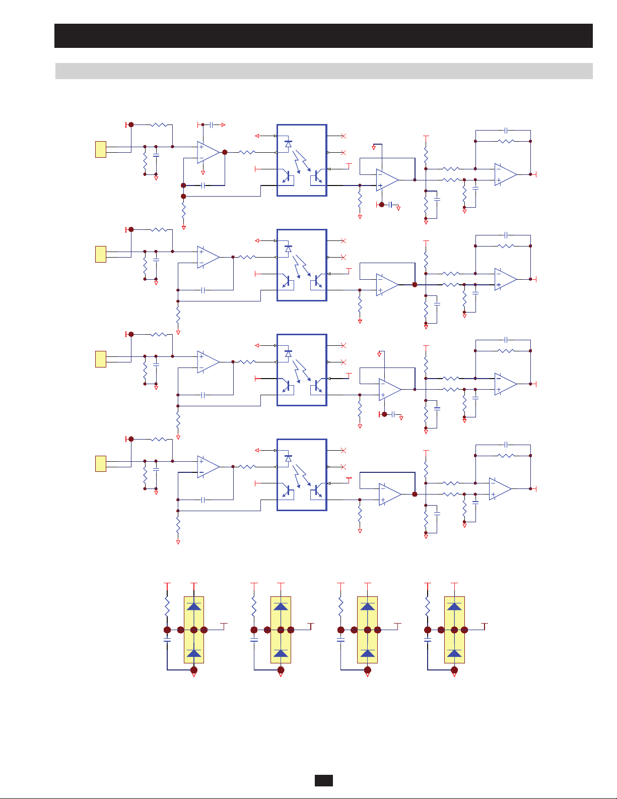
2 Theory of Operation (continued)
2.18 External Battery Cabinet Temperature Detection
Located on NH-SYS-X board (Circuit for REPO, Input Dry Contact and Circuit for sense External Battery Cabinet Temperature)
CX1
+12VSF G4
4 11
UX5A
3
2
G4
CX5
RX13
G4
5
6
CX12
RX29
G4
10
9
CX19
RX46
G4
12
13
CX28
RX59
G4
UX5B
UX5C
UX5D
UX1
1
G4
RX5
1
+12VSF
RX21
7
+12VSF
RX38
8
+12VSF
RX52
14
+12VSF
2
3
4
UX2
1
G4
2
3
4
UX3
1
G4
2
3
4
UX4
1
G4
2
3
4
8
N/C
7
N/C
6
5
8
N/C
7
N/C
6
5
8
N/C
7
N/C
6
5
8
N/C
7
N/C
6
5
+12VS
RX16
+12VS
RX31
+12VS
RX48
+12VS
RX62
G1
2
3
411
+12VS
G1
13
12
G1
G1
2
3
411
+12VS
G1
13
12
G1
UX6A
CX8
UX6D
UX7A
CX21
UX7D
1
RX17G1CX9
G1
14
RX32G1CX15
1
G1
14
RX63G1CX34
10VS_REF
10VS_REF
10VS_REF
RX39
RX49
10VS_REF
RX53
RX6
RX8
RX11
RX14
RX22
RX23
RX27
RX30
RX40
RX43
RX47
CX23
G1
RX54
RX58
RX60
CX2
RX4
UX6B
6
5
CX6
G1
9
10
CX13
G1
6
5
CX20
G1
9
10
CX32
G1
CX10
RX20
CX16
RX36
CX24
RX51
UX7C
UX6C
UX7B
8
7
8
7
#EXTB_TEMP1
#EXTB_TEMP2
#EXTB_TEMP3
#EXTB_TEMP4
RX9
RX24
RX41
RX1
CX4
G4
RX18
CX11
G4
RX33
CX18
G4
10VSF_REF
CNX6
1
2
EXTB_TEMP1
10VSF_REF
CNX7
1
2
EXTB_TEMP2
10VSF_REF
CNX8
1
2
EXTB_TEMP3
PRELIMINARY
RX55
RX50
CX27
G4
10VSF_REF
CNX11
1
2
EXTB_TEMP4
Located on NH-SYS-M board (System MCU and Control Circuit)
#EXTB_TEMP1
RM69
CM35
5VS
#EXTB_TEMP2
RM17 1
(104)
EXTB_TEMP 1
3
CM132
DM18
12
G1
5VS
#EXTB_TEMP3
RM172
(106)
EXTB_TEMP 2
3
CM13 3
DM36
12
G1
5VS
#EXTB_TEMP 4
5VS
RM17 3
(111)
EXTB_TEMP 3
3
CM13 4
DM37
12
3
12
G1
G1
(112)
EXTB_TEMP 4
DM38
(a) UX1, UX2, UX3 and UX4 are linear photo.
(b) CNX6, CNX7, CNX8 and CNX11 connect the NTC to the external battery cabinet.
(c) System MCU detects the external battery cabinet temperature via EXTB_TEMP1 (104) for battery cabinet 1, EXTB_TEMP2 (106) for battery
cabinet 2, EXTB_TEMP3 (111) for battery cabinet 3, and EXTB_TEMP4 (112) for battery cabinet 4.
65
Page 48

2 Theory of Operation (continued)
2.19 Detection Circuit for Manual Bypass Switch
Located on NH-SYS-R board (Circuit for RS232, Output Dry Contact, Parallel Port, Connector to connect with each Power Module,
Circuit for 2 Slots)
DR15
+12VSF
TOMBYP
CNR1 3
TO Manual Bypass Breaker
Located on NH-SYS-M board (System MCU and Control Circuit)
TOMBYP_I
(6)
RR10 2
CR66
1
2
RM1 4 6
RR10 7
G4
UR43
1
2
CR73
#TOMBYP_I
RR10 3
4
3
G1
5VS
#TOMBYP_I
CR65
CM102
G1
(a) CNR13 connects to the auxiliary contact of the manual bypass switch.
(b) System MCU detects the status of the manual bypass switch via TOMBYP_I (6). Manual bypass switch will stay in the OFF position and
TOMBYO_I (6) will be high.
2.20 Detection Circuit for Output Breaker
Located on NH-SYS-R board (Circuit for RS232, Output Dry Contact, Parallel Port, Connector to connect with each Power Module, Circuit for 2
Slots)
Located on NH-SYS-M board (System MCU and Control Circuit)
PRELIMINARY
+12VSF
CNR1 0
1
2
RR7 5
RR7 9CR5 4
G4
OPCBAUX_I
(72)
CR5 8
RR7 4
UR33
1
2
4
3
G1
5VS
#OP CBAUX_I
CR5 3
RM1 5 1
#OP CBAUX_I
CM108
G1
(a) CNR10 connects to the auxiliary contact of the output breaker.
(b) System MCU detects the status of the output breaker via OPCBAUX_I (72). Output breaker stays in the OFF position and OPCBAUX_I (72)
will be high.
66
Page 49

2 Theory of Operation (continued)
VS
RR106
RR10 0
G1
QR11
+12VSF
1
2
4
3
UR42
5VS
QR12
RR11 1
RR10 8
G4
RR105
CENTRAL_OK
RR81
CR56
1
2
4
3
UR35
RR78
BYP _ O K
+12VS
DR13
+12VSF
G4
BYP O K
QR14
RR13 8
+12VSF
RR13 7
2.21 Control Circuit for Power Module
Located on NH-SYS-R board (Circuit for RS232, Output Dry Contact, Parallel Port, Connector to connect with each Power Module,
Circuit for 2 Slots)
Located on NH-SYS-M board (System MCU and Control Circuit)
PRELIMINARY
UM5
8
7
6
5
4
3
2
1
ULN2003A
G1
U-LED0
(73)
U-LED1
(74)
U-LED2
(75)
U-LED3
(76)
U-LED4
(77)
U-LED5
(a) VS is the voltage source for the parallel signal bus. CENTRAL_OK signal is controlled by the system MCU’s watchdog circuit.
(b) The BYPOK signal indicates that the system MCU is functioning properly.
(70)
(78)
CEN T RAL _ OK
GND
7B
6B
5B
4B
3B
2B
1B
COM
7C
6C
5C
4C
3C
2C
1C
9
10
11
12
13
14
15
16
LED0
LED1
LED2
LED3
LED4
LED5
BYP _ O K
67
Page 50

2 Theory of Operation (continued)
(41)
(40)
(31)
(30)
(29)
(28)
RM106
200
CM57
103
G1
#ID1_OK
RM110
200
CM61
103
G1
#ID2_OK
RM114
200
CM65
103
G1
#ID3_OK
RM119
200
CM70
103
G1
#ID4_OK
RM124
200
CM83
103
G1
#ID5_OK
RM130
200
CM88
103
G1
#ID6_OK
ID1_OK
ID2_OK
ID3_OK
ID4_OK
ID5_OK
ID6_OK
2 15
UM8B
ON1
(42)
CM99
G1
POWER_ON
2.21 Control Circuit for Power Module (continued)
Located on NH-SYS-R board (Circuit for RS232, Output Dry Contact, Parallel Port, Connector to connect with each Power Module,
Circuit for 2 Slots)
RR133
681
TO PM4 TO PM5 TO PM6TO PM1 TO PM2 TO PM3
CNR2 5
CI33(V) -4P
1
ID4OK
2
3
4
ON
RR128
CNR2 6
1
ID5OK
2
3
4
CI33(V) -4P
ON
RR129
1K1
RR134
1K21
CNR2 7
1
ID6OK
2
3
4
CI33(V) -4P
ON
RR130
2K61
RR136
2K61
1K65
RR135
1K82
CNR2 0
1
2
3
4
CI33(V)-4P
ID1OK
ON
RR125
100
RR131
100
CNR2 1
1
2
3
4
CI33(V)-4P
ID2OK
ON
RR126
365
RR132
365
CNR2 2
1
2
3
4
CI33(V) -4P
ID3OK
ON
RR127
681
+12VSF
+12VSF
+12VSF
G4
RR29
2K
DR2
1N4148
RR36
2K
DR5
1N4148
RR46
2K
DR7
1N4148
1
2
ID1OK
1
2
ID2OK
1
2
ID3OK
UR14
TLP421( GRL)
UR18
TLP421( GRL)
UR22
TLP421( GRL)
G4
+12VSF
G4
RR25
10K
4
3
4
3
4
3
G1
G1
G1
RR96
CR23
104
RR34
10K
CR29
104
RR45
10K
CR34
104
ON
Located on NH-SYS-M board (System MCU and Control Circuit)
PRELIMINARY
4
3
5VS
#ID1_OK
5VS
#ID2_OK
5VS
#ID3_OK
UR41
+12VSF
+12VSF
+12VSF
G4
RR53
2K
DR9
1N4148
RR64
2K
DR11
1N4148
RR72
2K
DR12
1N4148
RR97
1
2
ID4OK
ID5OK
ID6OK
ON1
UR26
1
2
TLP421(GRL)
UR28
1
2
TLP421(GRL)
UR32
1
2
TLP421(GRL)
+12VS
G4
4
3
4
3
4
3
G4
RR52
10K
CR41
104
G1
RR59
10K
CR48
104
G1
RR71
10K
CR51
104
G1
5VS
#ID4_OK
5VS
#ID5_OK
5VS
#ID6_OK
(c) System MCU can detect the status of the power module DSP chip via ID1_OK (28), ID2_OK (29), ID3_OK (30), ID4_OK (31), ID5_OK
(40) and ID6_OK (41). “Logic Low” means that the power module DSP chip is functioning properly. (ID5_OK and ID6_OK are not used for
reserve.)
(d) ON is connected to the relay driver of the auxiliary power supply inside the power module. If POWER_ON (42) is “Logic H,” then the auxiliary
power supply inside the power module is on.
68
Page 51
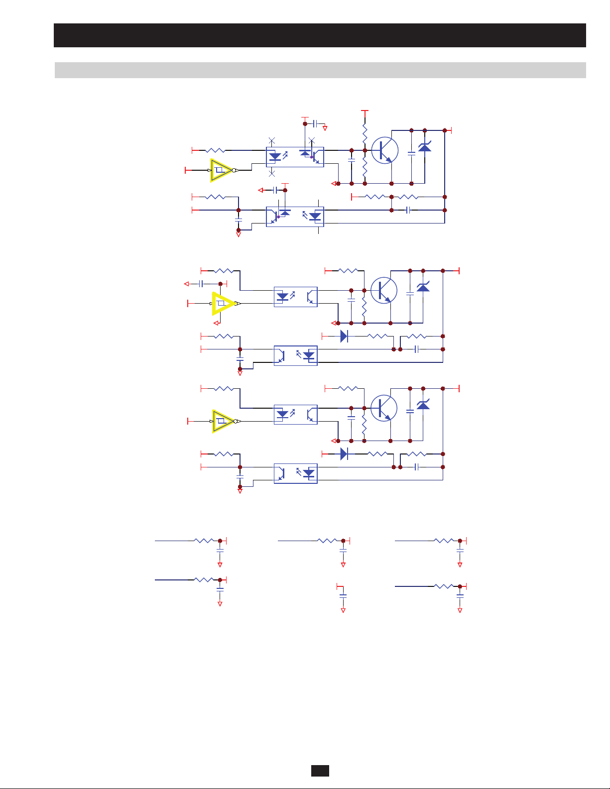
2 Theory of Operation (continued)
2.21 Control Circuit for Power Module (continued)
Located on NH-SYS-M board (System MCU and Control Circuit)
#DATA_TX
#DATA_RX
5VS
5VS
RR54
RR61
UR4D
CR47
1 4
UR24
2
3
89
5VS
G1
8
7
CR43
6
5
G1
UR30
8
+12VSF
7
1 4
CR35
VS
CR39
RR56
RR62
RR50
CR37
QR7
RR63
CR46
G4
6
5
G4
+12VSF
2
3
DATA_BUS
ZR4
RR1
5VS
CR8
G1
#TOBYP_O
5VS
#TOBYP_I
5VS
PRELIMINARY
#TOINV_O
5VS
#TOINV_I
5VS
14
1 2
UR4A
7
G1
RR8
CR10
RR12
UR4B
3 4
RR18
CR19
G1
G1
UR3
1
2
UR6
4
3
UR7
1
2
UR10
4
3
+12VSF
+12VSF
RR2
VS TOBYP
CR4
4
3
G4
DR16
1
2
RR13
VS TOINV
CR15
4
3
G4
DR17
1
2
RR6
RR9
RR16
RR19
QR1
ZR1
CR7
RR10
CR9
QR2
ZR2
CR16
RR20
CR18
Located on NH-SYS-M board (System MCU and Control Circuit)
(120)
DATA_TX
RM136
#DATA_TX
CM93
(131)
TOBYP_I
RM14 1
#TOBYP_I
CM97
(130)
TOINV_I
RM150
#TOINV_I
CM10 7
(119)
DATA_RX
RM142
G1
CM98
G1
#DATA_RX
#TOBYP _O
G1
TOINV_O
(46)
CM92
G1
RM145
G1
#TOINV_O
CM10 1
G1
(e) DATA_BUS is the communication bus between the system and its power modules. This signal also connects to the external parallel port.
(f) TOBYP and TOINV are used to control the bypass or inverter transfer. The system frame and power module determine these signals together.
These signals also connect to the external parallel port.
69
Page 52

2 Theory of Operation (continued)
2.21 Control Circuit for Power Module (continued)
Located on NH-SYS-R board (Circuit for RS232, Output Dry Contact, Parallel Port, Connector to connect with each Power Module,
Circuit for 2 Slots)
CR12
5VSF G4
2
3
VCC
CANH - M
RR17
CANL-M
CANH7TXD
6
Rs
CANL
8
GND
RXD
Vre f
UR8
G4
Located on NH-SYS-M board (System MCU and Control Circuit)
CANM_ T X CANM_ RX
(134)
CR14
G4
RR15
1
4
5VSF
5
RR21
UR9
8 1
7
6
5
G4
UR11
2
3
4
SHIELD
SHIELD
5VS
5VS5VSF
RR14
2
3
4
81
7
6
5
G1
CR17
RR22
CANM_ T X
G1
CANM_ RX
(135)
CM106
CM109
G1
G1
(g) CAN bus is the communication bus for load sharing, as well as the synchronization of signals between the system and its power modules.
Control Circuit for External Parallel
Located on NH-SYS-R board (Circuit for RS232, Output Dry Contact, Parallel Port, Connector to connect with each Power Module,
Circuit for 2 Slots)
CR1
1
4
5
DR15
TOMBYP
CNR1 3
CR2
G4
RR4
5VSF
RR7
RR10 2
RR10 7
CR66
1
2
UR2
8 1
7
6
5
G4
UR5
2
3
4
SHI EL D
UR43
1
2
CR73
G4
SHI EL D
5VS
5VS5VSF
RR3
2
3
4
81
7
6
5
G1
4
3
G1
CR6
RR10 3
RR11
CANS_ T X
G1
CANS_ RX
5VS
#TOMBYP_I
CR65
PRELIMINARY
Parallel Port
CNR1 4
1
6
2
7
3
8
4
9
5
G4
TOMBYP
SYNC_BUS
TOINV
TOBYP
CANH-S
CANL - S
CANH-S
CANL-S
5VSF G4
3
VCC
CANH7TXD
RR5
6
CANL
8
2
GND
Rs
+12VSF
RXD
Vre f
UR1
G4
Located on NH-SYS-M board (System MCU and Control Circuit)
(136)
CANS_TX
(6)
TOMBYP _I
CM95
(137)
CANS_RX
G1
RM146
#TOMBYP_I
CM102
G1
CM100
G1
(h) CAN bus is the communication bus for load sharing, and also synchronizes signals between the two systems.
(i) TOMBYP is the status of the manual bypass switch on the system frame. When the manual bypass switch turns on, MCU can detect its status
via TOMBYP_I(6) and auto-transfer to bypass the mode and its alarm.
70
Page 53
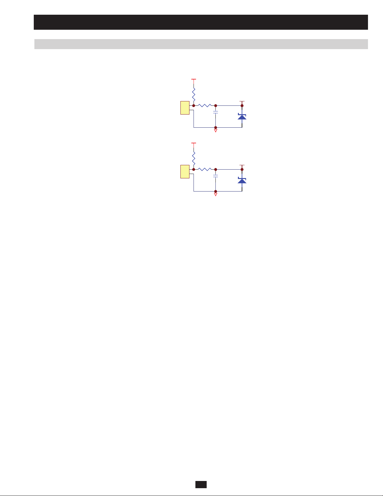
2 Theory of Operation (continued)
2.22 Transformer Over Temperature Detection
(This function is only for SU40K, SU60K, SU80K, SU60KTV, and SU80KTV models)
Located on NH-M board (System MCU and Control Circuit)
5VS
RM4
1K
CNM10
RM17 5
TO OUTPUT XFMR
TO INP UT XFMR
2
1
CON2
CNM11
2
1
CON2
5VS
392
RM8
1K
RM17 6
392
CM13 7
104
G1
CM13 8
104
G1
OPRT Te mp
ZD4
5V1
IPRT Temp
ZD5
5V1
(61)
(51)
(a) CNM10 connects to the output transformer, CNM11 connects to the input transformer.
(b) Thermal switch sensors are mounted on the coils of the transformer.
(c) The thermal switch sensor will be open when the transformer coil’s temperature exceeds 150. MCU can detect the temperature status through
IPRT_Temp (51) and OTRT_Temp (61).
Note: For international models (SU20KX, SU40KX, SU60KX and SU80KX), short-pins must be inserted into CNM10 and CNM11.
PRELIMINARY
71
Page 54

3 Communication
Warning: Do not use the paralleling cable that came with the UPS system for these procedures.
Use a RS232 cable.
3.01 RS232 Port
The UPS provides a RS232 port in one D-sub 9 female connector. This RS232 port performs the following functions:
3.1) Sets EEPROM on the NH-M board
3.2) Sets Output Dry Contact status
3.3) Upgrades the system board’s fi rmware
3.4) Upgrades the power module’s DSP fi rmware
3.5) Downloads the event log of the UPS
Use the straight through serial connection to communicate with the RS232 port. The pin assignment of the RS232 port D-sub 9 female connector is
defi ned as follows:
Figure 3.01a RS232 Pin Assignment
Pin 2: PC receives line RS-232 data from UPS.
Pin 3: PC transmits line RS-232 data to UPS.
Pin 5: Signal ground.
3.02 Emergency Power Off (EPO)
The EPO button on the front control panel (Figure 3.02a) turns the UPS system’s output OFF and also disables its bypass output.
If the UPS system is in battery backup mode when the EPO button is activated:
• Main output and bypass output are turned off, the alarm sounds, fans shut down after approximately one minute, and control circuitry remains
active.
• Pressing the EPO button again turns off the UPS system completely, including the alarm and control circuit. Press the ON button for three seconds to restart the UPS system.
If the UPS system is in online (normal) mode when the EPO button is activated:
• Main output and bypass output are turned off, the alarm sounds, fans and control circuitry remain active.
• Pressing the EPO button again turns off the alarm and places the UPS system in auto bypass mode. Press the ON button for three seconds to
return the UPS system to online (normal) mode.
PRELIMINARY
Fig 3.02a Front Control Panel
72
Page 55

3 Communication (continued)
Remote Emergency Power Off (REPO)
The Remote Emergency Power Off (REPO) input connection (P1 in Figure 3.02b) allows you to connect the UPS system to your facility’s EPO
circuit — enabling remote emergency shutdown of the UPS system’s output. Connect EPO input to a user-supplied remote switch using the circuit
diagram (Figure 3.02c).
Fig 3.02b
UPS
Note: This contact is normally open.
PRELIMINARY
4
3
1
2
12Vdc
2
1
G4
Fig 3.02c
73
Page 56

3 Communication (continued)
3.1 Setting EEPROM on the NH-M Board
3.1.1 Polling and Updating EEPROM
WARNING: This procedure must be performed in bypass mode (see section 1.6).
Instructions for polling and updating the EEPROM are as follows (Figure 3.1.1a):
a) Link the UPS with a PC via the RS232 port
b) Run the program “NH_SYS_V1_3B1030.exe”
c) Click the “EEPROM” icon
d) Select the PC COM Port and click “Open COM Port”
e) Click “Polling” to download the EEPROM data from the UPS.
f) Save the fi le to ensure that you have the values in case they are needed later
g) After setting the data, click “Update All” and wait for the procedure to complete itself
EEPROM
PRELIMINARY
Fig 3.1.1a
74
Page 57

3 Communication (continued)
3.1 Setting EEPROM on the NH-M Board (continued)
3.1.2 Calibrating EEPROM Gain
WARNING: This procedure must be performed in bypass mode (see section 1.6).
Instructions for calibrating the EEPROM gain of the UPS parameters are as follows:
(For polling procedure, please refer to section 3.1.1)
a) Click the “Gain” tab (Figure 3.1.2a)
PRELIMINARY
Fig 3.1.2a
b) Select the parameter you want to calibrate and click its gain icon
c) Key in the actual value to the “Actual Measured:” column of the dialogue box
d) Key in the LCD value to the “UPS Detected:” column of the dialogue box
e) Click the “Calculate” icon (the New Gain Value will auto-calculate)
f) Click the “OK” icon (the dialogue box will close)
g) After calibrating the gain, click “Update All” and wait for the procedure to complete itself
75
Page 58
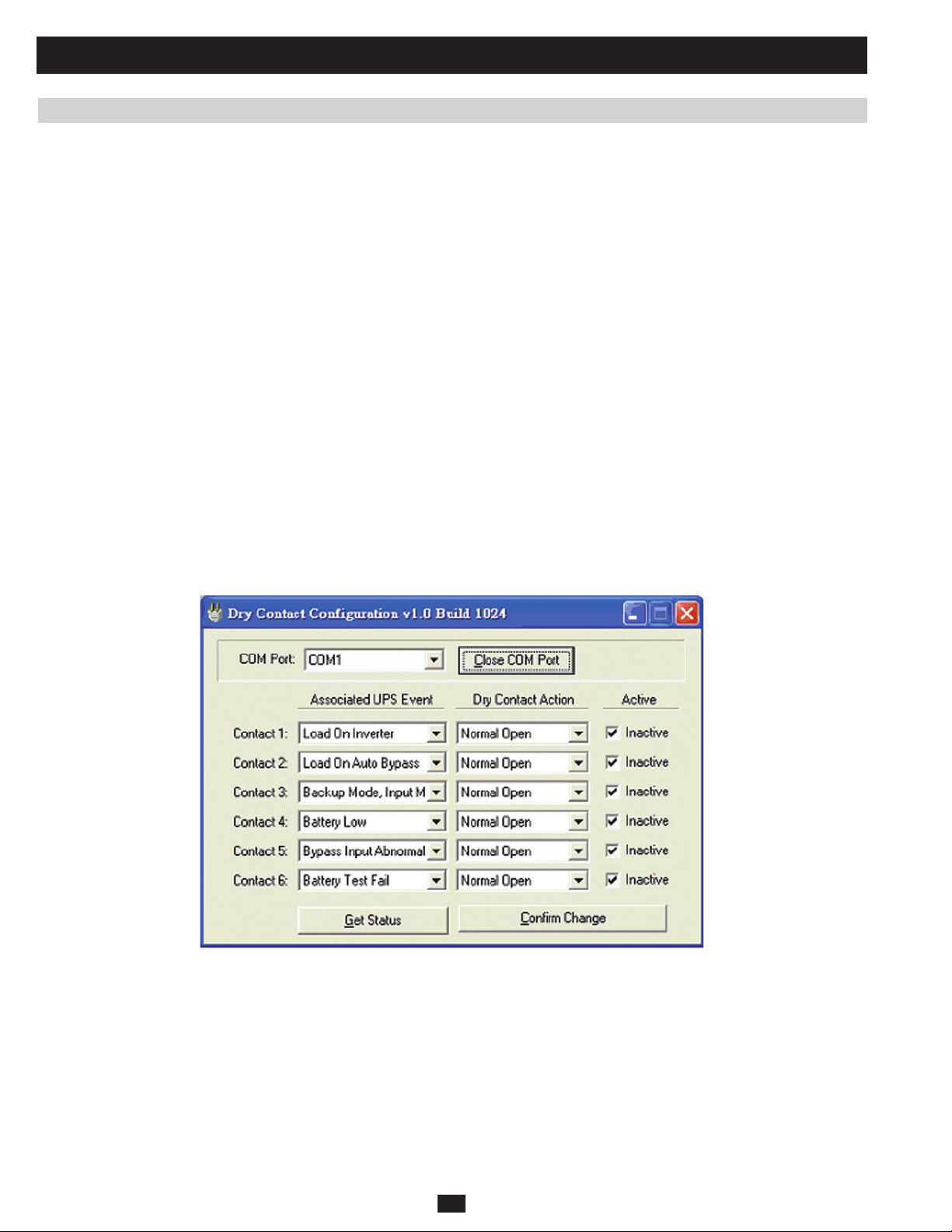
3 Communication (continued)
3.2 Setting Output Dry Contact Status
The UPS provides six output dry contact closures. The status of each output dry contact closure can be programmed from 19 status events:
1. Load on inverter (Default)
2. Load on auto bypass (Default)
3. Backup mode input main failure (Default)
4. Battery low (Default)
5. Bypass input abnormal (Default)
6. Battery test failure (Default)
7. Internal communication failure
8. External parallel communication failure
9. Output overload warning/shutdown
10. Power module fault shutdown
11. Power module warning
12. EPO activated
13. Load on manual bypass
14. Battery cabinet over temperature warning/shutdown
15. Output voltage abnormal
16. Battery need replace
17. Bypass over temperature warning/shutdown
18. Battery ground fault
19. Bypass static switch fault
PRELIMINARY
Fig 3.2a
To change the status of an output dry contact closure:
(a) Link the UPS with a PC via the RS232 port
(b) Run the program “NH-Dry-Contact v1.0b1024.exe” (Figure 3.2a)
(c) Select the PC COM Port and click “Open COM Port”
(d) Click “Get Status” to poll the UPS settings
(e) After you change the status, click “Confi rm Change” to update the UPS settings
76
Page 59

3 Communication (continued)
3.3 Upgrading Firmware for the System Board
WARNING: Make sure that the UPS is in bypass mode and that all power modules have been completely
de-energized.
WARNING: When the system is in manual bypass mode, bypass power is still present in the output
terminal block.
Before upgrading your fi rmware, please verify the fi rmware version using the control panel (Figure 3.3a).
(Maintenance Others SN & FW Version)
E
R
U
SAEM
SAEM
SPU
SPU
NIAM
NIAM
PRELIMINARY
E
R
U
T
E
S
T
E
S
E
T
E
T
SREHTO
SREHTO
ECNPAUN
ECNPAUN
ECNANETNIAM
ECNANETNIAM
CITSITATS
CITSITATS
GOLTNEVE
GOLTNEVE
TSET&PUTESLAUNAM
TSET&PUTESLAUNAM
EDARGPUERAWMRIF
EDARGPUERAWMRIF
SREHTO
SREHTO
NOISREVWF&NS
NOISREVWF&NS
EMITMETSYS
EMITMETSYS
TLOVSUBCDELUDOM
TLOVSUBCDELUDOM
Fig 3.3a
77
Page 60

3 Communication (continued)
3.3 Upgrading Firmware for the System Board (continued)
To upgrade the system’s fi rmware:
a) Confi rm that the Main Input Breaker (Q1) and Output Breaker (Q4) are both OFF, and that Bypass Input Breaker (Q2) and Manual Bypass
Breaker (Q3) are both ON (Figure 3.3b).
Q4 Q3 Q2 Q1
Output
Q1: Input Circuit Breaker
Q2: Bypass Input Circuit Breaker
Q3: Manual Bypass Circuit Breaker
Q4: Output Circuit Breaker
Fig 3.3b
Manual
Bypass
Bypass
Input
Main
Input
PRELIMINARY
78
Page 61
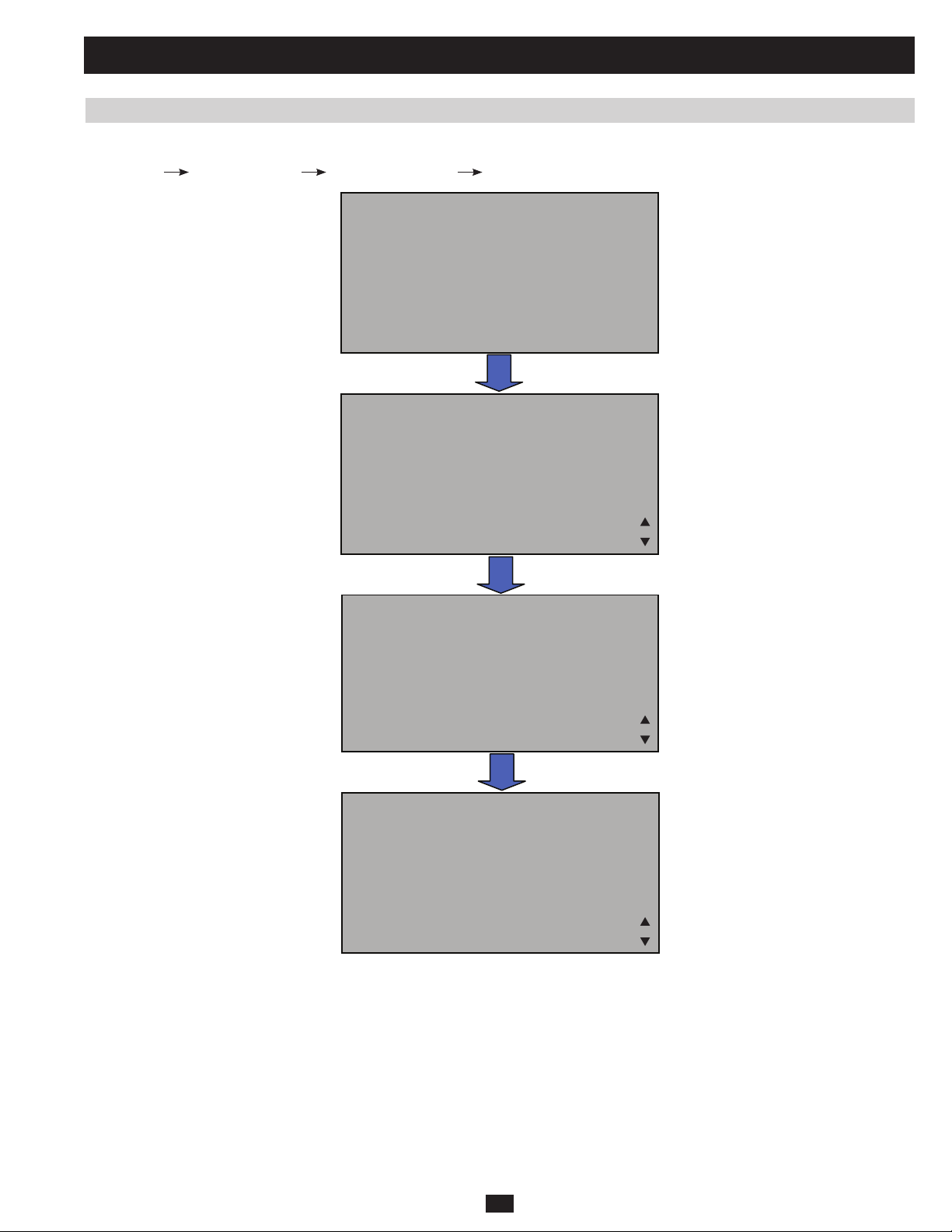
3 Communication (continued)
3.3 Upgrading Firmware for the System Board (continued)
b) Select “System Firmware Upgrade” using the LCD panel (Figure 3.3c).
(Maintenance
Firmware Upgrade Login (Administrator) System Firmware)
E
R
U
SAEM
E
R
U
SAEM
T
E
S
SPU
SPU
T
E
S
E
T
NIAM
E
T
NIAM
SREHTO
SREHTO
ECNPAUN
ECNPAUN
ECNANETNIAM
ECNANETNIAM
CITSITATS
CITSITATS
GOLTNEVE
GOLTNEVE
TSET&PUTESLAUNAM
TSET&PUTESLAUNAM
EDARGPUERAWMRIF
EDARGPUERAWMRIF
NIGOL
NIGOL
IMDA
PRELIMINARY
IMDA
RESU
RESU
METSYS
METSYS
Fig 3.3c
ROTARTSIN
ROTARTSIN
EDARGPUERAWMRIF
EDARGPUERAWMRIF
ELUDOMREWOP
ELUDOMREWOP
79
Page 62

3 Communication (continued)
3.3 Upgrading Firmware for the System Board (continued)
c) After confi rming the command, wait for the LCD to display “READY TO DOWNLOAD FIRMWARE!” (Figure 3.3d).
EDARGPUWFMETSYS
EDARGPUWFMETSYS
DEWOLLAGNITTES:ETON
DEWOLLAGNITTES:ETON
LAUNAMTANEHWYLNO
LAUNAMTANEHWYLNO
EDOMSSAPYB
EDOMSSAPYB
?ERUSUOYERA
?ERUSUOYERA
SEY
SEY
…GNITIAW
…GNITIAW
EDARGPUWFMETSYS
EDARGPUWFMETSYS
EDARGPUWFMETSYS
EDARGPUWFMETSYS
DAOLNWODOTYDAER
DAOLNWODOTYDAER
!ERAWMRIF
PRELIMINARY
Note 1: Once you confi rm the command, the system will go into “system fi rmware upgrade” mode. If you want to cancel the upgrade command
before programming, the BYPASS input breaker (Q2) must be turned off.
Note 2: The Firmware Upgrade setting is only allowed in manual bypass mode.
d) Link the UPS with a PC via the RS232 port.
!ERAWMRIF
Fig 3.3d
80
Page 63
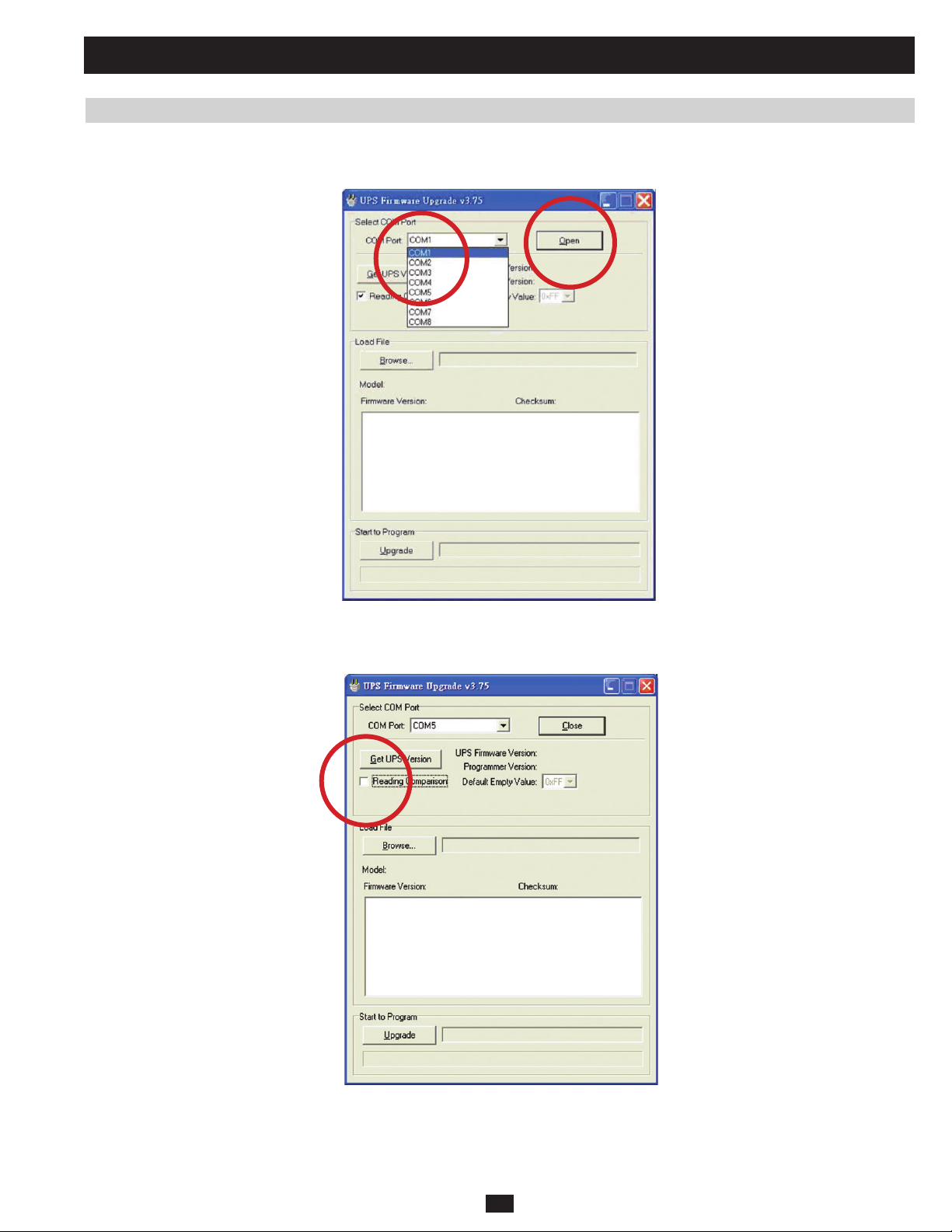
3 Communication (continued)
3.3 Upgrading Firmware for the System Board (continued)
e) Run the program “FSL 3.75.exe” (Figure 3.3e).
f) Select the PC COM Port and Click “Open.”
Fig 3.3e
g) Disable “Reading Comparison” (Figure 3.3f).
PRELIMINARY
Fig 3.3f
81
Page 64

3 Communication (continued)
3.3 Upgrading Firmware for the System Board (continued)
h) Load the new fi rmware fi le and click “Upgrade” (Figure 3.3g).
Fig 3.3g
i) Once the system fi nished upgrading its fi rmware, it will auto-reset into manual bypass mode (Figure 3.4h).
PRELIMINARY
LOAD UNPROTECTED
LOAD UNPROTECTED
ON MANUAL BYPASS
ON MANUAL BYPASS
BYPA.
BYPA.
BYPA.
MAINS
MAINS
MAINS
Fig 3.3h
!
!
!
3.4 Upgrading Firmware for the Power Module
WARNING: Make sure that the UPS is in bypass mode and that all power modules have been completely
de-energized.
WARNING: When the system is in manual bypass mode, bypass power is still present in the output
terminal block.
82
Page 65

3 Communication (continued)
3.4 Upgrading Firmware for the Power Module (continued)
Before upgrading your fi rmware, please verify the fi rmware version using the control panel (Fig 3.4a).
(Maintenance
Others SN & FW Version)
SAEM
SAEM
SPU
SPU
NIAM
NIAM
E
R
U
T
E
S
T
E
S
E
T
E
T
SREHTO
SREHTO
ECNPAUN
ECNPAUN
ECNANETNIAM
ECNANETNIAM
CITSITATS
CITSITATS
GOLTNEVE
GOLTNEVE
TSET&PUTESLAUNAM
TSET&PUTESLAUNAM
EDARGPUERAWMRIF
EDARGPUERAWMRIF
E
R
U
SREHTO
SREHTO
NOISREVWF&NS
EMITMETSYS
EMITMETSYS
PRELIMINARY
To upgrade the power module’s fi rmware:
Fig 3.4a
NOISREVWF&NS
TLOVSUBCDELUDOM
TLOVSUBCDELUDOM
a) Confi rm that the Main Input Breaker (Q1) and Output Breaker (Q4) are both OFF, and that the Bypass Input Breaker (Q2) and Manual Bypass
Breaker (Q3) are both ON. (Figure 3.4b)
PM1
PM2
Q4 Q3 Q2 Q1
Output
Manual
Bypass
Bypass
Input
Main
Input
PM3
PM4
Q1: Input Circuit Breaker
Q2: Bypass Input Circuit Breaker
Q3: Manual Bypass Circuit Breaker
Q4: Output Circuit Breaker
Fig 3.4b
83
Page 66

3 Communication (continued)
3.4 Upgrading Firmware for the Power Module (continued)
Note: Confi rm that you’ve turned on the breaker for the external battery cabinet or internal battery.
b) Select “Power Module Firmware Upgrade” using the LCD panel. (Figure 3.4c) (Maintenance
tor)
Power Module Firmware)
SAEM
SAEM
SPU
SPU
NIAM
NIAM
E
R
U
T
E
S
T
E
S
E
T
E
T
SREHTO
SREHTO
ECNPAUN
ECNPAUN
ECNANETNIAM
ECNANETNIAM
CITSITATS
CITSITATS
GOLTNEVE
GOLTNEVE
EDARGPUERAWMRIF
EDARGPUERAWMRIF
E
R
U
Firmware Upgrade Login (Administra-
TSET&PUTESLAUNAM
TSET&PUTESLAUNAM
NIGOL
NIGOL
IMDA
PRELIMINARY
IMDA
RESU
RESU
METSYS
METSYS
Fig 3.4c
ROTARTSIN
ROTARTSIN
EDARGPUERAWMRIF
EDARGPUERAWMRIF
ELUDOMREWOP
ELUDOMREWOP
84
Page 67

3 Communication (continued)
3.4 Upgrading Firmware for the Power Module (continued)
c) Select “ON” to upgrade the power module’s fi rmware and press “
DOWNLOAD FIRMWARE!” (Figure 3.4d).
NO
NO
FFO
FFO
NO
NO
FFO
FFO
…GNITIAW
…GNITIAW
” to confi rm the command. Wait for the LCD to display “READY TO
EDARGPUWFDOMRWP
EDARGPUWFDOMRWP
DEWOLLAGNITTES:ETON
DEWOLLAGNITTES:ETON
LAUNAMTANEHWYLNO
LAUNAMTANEHWYLNO
EDOMSSAPYB
EDOMSSAPYB
?ERUSUOYERA
?ERUSUOYERA
SEY
SEY
EDARGPUWFDOMRWP
EDARGPUWFDOMRWP
EDARGPUWFDOMRWP
EDARGPUWFDOMRWP
NO
NO
FFO
FFO
PRELIMINARY
!ERAWMRIF
!ERAWMRIF
Fig 3.4d
Note 1: Once you confi rm the command, the system will go into “system fi rmware upgrade” mode. If you want to cancel the upgrade command
before programming, the BYPASS input breaker (Q2) must be turned off.
Note 2: The Firmware Upgrade setting is only allowed in manual bypass mode.
d) Link the UPS to a PC via the RS232 port.
DAOLNWODOTYDAER
DAOLNWODOTYDAER
85
Page 68

3 Communication (continued)
3.4 Upgrading Firmware for the Power Module (continued)
e) Run the program “NH_PM_V1_4B1207.exe” (Figure 3.4e).
f) Click the “Firmware Upgrade” icon, select PC COM Port and click “Open COM Port.”
PRELIMINARY
Fig 3.4e
g) Select the PFC DSP chip or INV DSP chip, along with power modules 1-4 (Figure 3.4f).
Fig 3.4f
86
Page 69
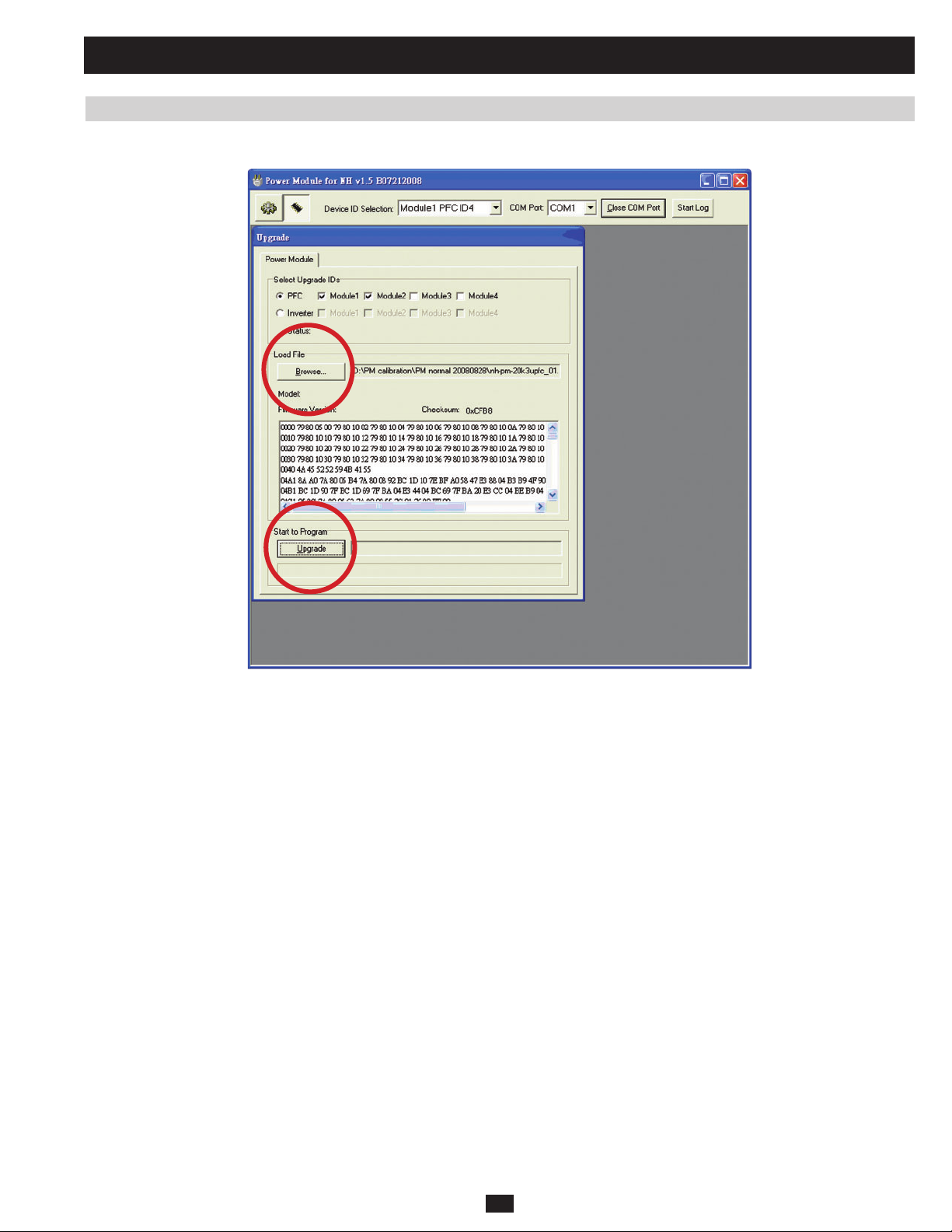
3 Communication (continued)
3.4 Upgrading Firmware for the Power Module (continued)
h) Load the new fi rmware fi le for the PFC (or Inverter) and click “Upgrade” (Figure 3.4g).
PRELIMINARY
Fig 3.4g
87
Page 70
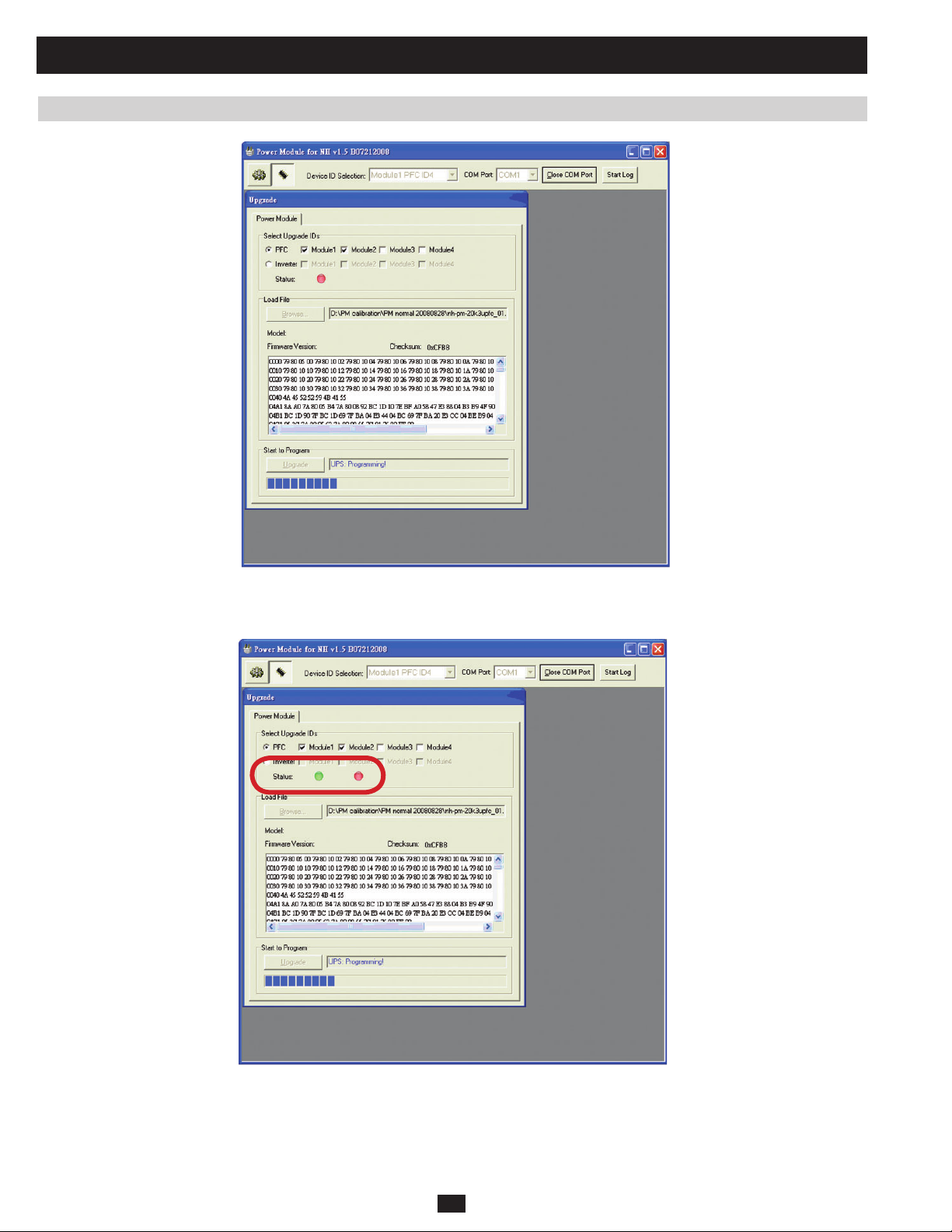
3 Communication (continued)
3.4 Upgrading Firmware for the Power Module (continued)
Fig 3.4h
Note 1: During programming, the status indicator is red. When upgrade is complete, the status indicator will turn green (Figure 3.4h).
PRELIMINARY
Fig 3.4i
Note 2: When one power module upgrade is complete, the system will automatically begin upgrading the next power module (Figure 3.4i).
88
Page 71
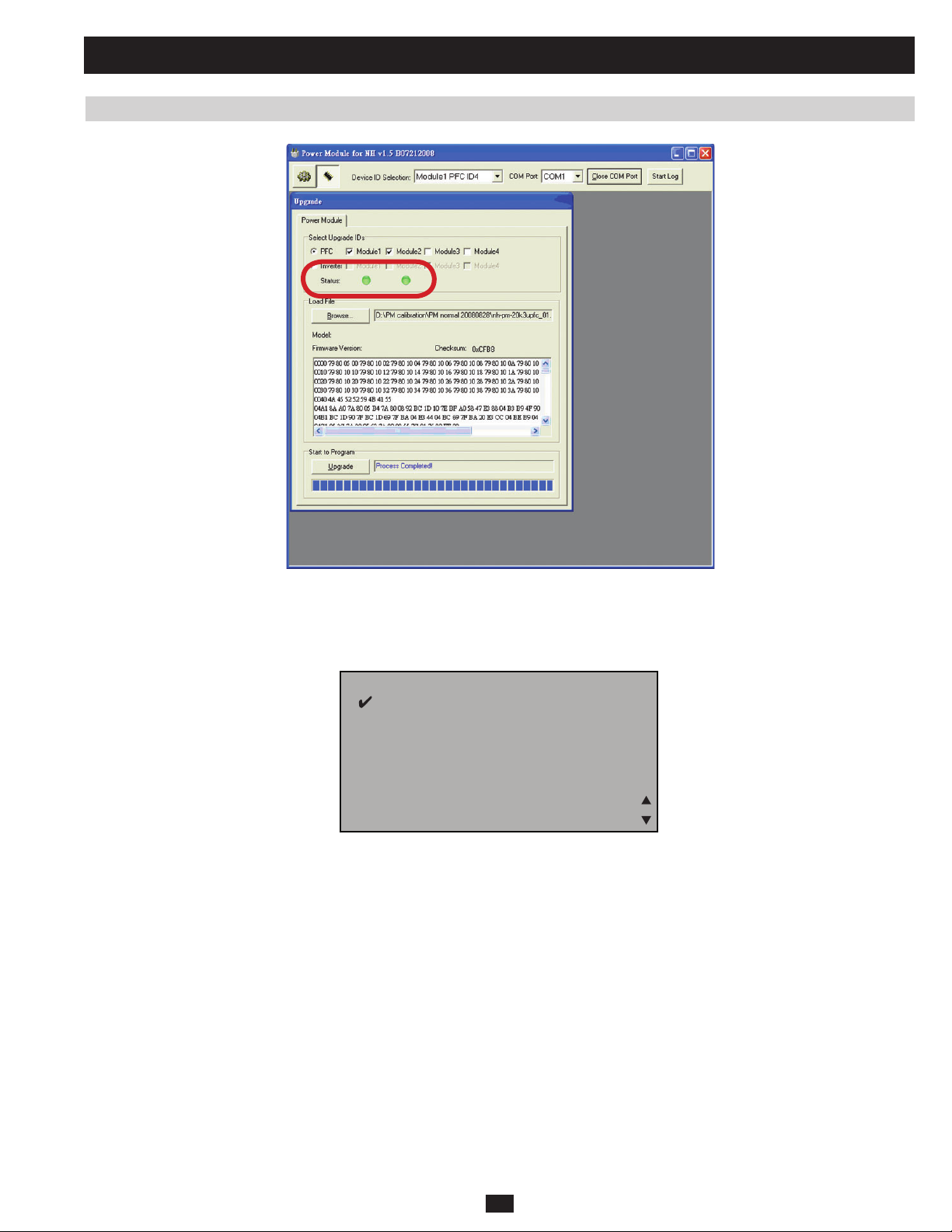
3 Communication (continued)
3.4 Upgrading Firmware for the Power Module (continued)
Fig 3.4j
Note 3: Once all power modules are complete, the status indicators will all turn green (Figure 3.4j).
i) Once all fi rmware upgrades are complete, select “OFF” to disable the power module fi rmware upgrade. (Figure 3.4k)
PRELIMINARY
EDARGPUWFDOMRWP
NO
NO
FFO
Note: When you disable the power module’s fi rmware upgrade, the power module will reset and shut down.
FFO
EDOMSSAPYB
EDOMSSAPYB
SEY
SEY
Fig 3.4k
EDARGPUWFDOMRWP
DEWOLLAGNITTES:ETON
DEWOLLAGNITTES:ETON
LAUNAMTANEHWYLNO
LAUNAMTANEHWYLNO
?ERUSUOYERA
?ERUSUOYERA
89
Page 72
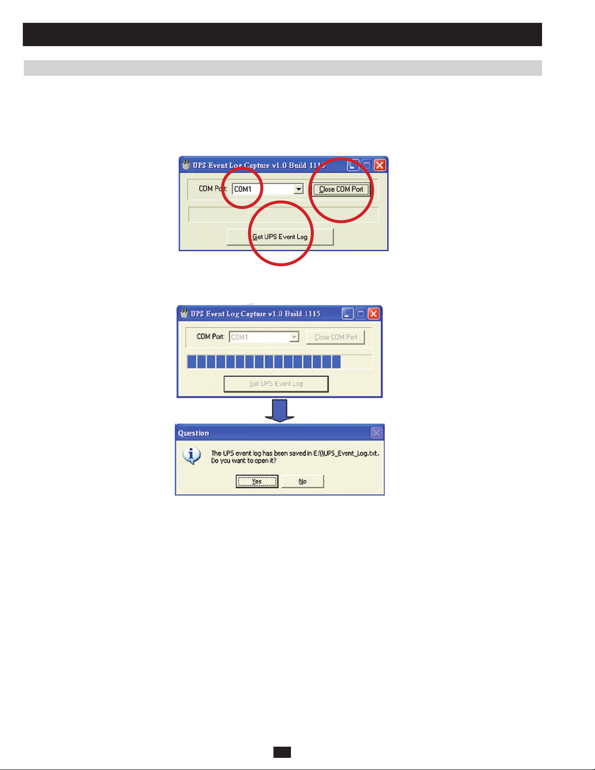
3 Communication (continued)
3.5 Downloading the Event Log
To download the UPS event log:
a) Link the UPS with a PC via the RS232 port.
b) Run the program “NH-EventLog v1.0b1115.exe” (Figure 3.5a).
c) Select PC COM Port and click “Open COM Port.”
d) Click “Get UPS Event Log” (Figure 3.5b).
Fig 3.5a
PRELIMINARY
Fig 3.5b
90
Page 73

4 Internal Battery
The SU20KX, SU40KX and SU40K models all use a +/-240Vdc (480V) DC internal battery system. An internal battery pack (number of packs
vary by model) supplies the UPS system with battery backup power. Each internal battery pack consists of 40 12Vdc VRLA batteries arranged in
two strings: one string of 20 positive batteries (black cable) and one string of 20 negative batteries (red cable). The two strings are connected by a
neutral (N) point (See Figure 4a).
B+ N B-
12Vdc, 20pcs 12Vdc, 20pcs
Fig 4a Battery Strings
All other KX, K and KTV models are designed with an external battery cabinet.
Both the SU20KX and SU40KX model’s internal battery space (Figure 4b) can hold eight battery packs. Each battery pack contains 10 batteries
(9AH, 12Vdc, VRLA), giving them a maximum capacity of 80 batteries.
PRELIMINARY
Fig 4b Front View of SU20KX and SU40KX Fig 4c Front View of SU40K
The SU20KX model’s standard battery quantity is 40, with a discharge time of about 5.5 minutes on full load. Upgrading to 80 batteries results in a
discharge time of about 13 minutes on full load.
The SU40KX and SU40K (Figure 4c) model’s standard battery quantity is 80, with a discharge time of about 5.5 minutes on full load.
91
Page 74

4 Internal Battery (continued)
4.1 Installing and Removing Internal Batteries
1
Place the UPS system in bypass (or turn it completely off) and turn •
off the internal battery circuit breaker switch, located on the rear of
the UPS system.
Remove the battery access bezels, located on the front of the UPS •
2
system.
1
3
Remove the battery cartridge fuses from each fuse block.•
PRELIMINARY
Disconnect the blue and white jumper cables attached to each fuse •
4
block. Warning: When disconnecting the jumper cables, pull
them straight away from the fuse block with even force. Do not
wiggle them side-to-side, as this may damage the connector.
5
Remove the fuse block bracket. Note its orientation before •
removal.
2
3
4
92
5
Page 75

4 Internal Battery (continued)
4.1 Installing and Removing Internal Batteries (continued)
6
Slide a battery string with a red cable into an empty slot within •
the battery compartment. Make sure the battery string is oriented
as shown in the diagram. Note: Start with the empty slots at the
bottom of the battery compartment and work toward the empty
slots at the top of the battery compartment.
7
Slide a battery string with a black cable into an empty slot within •
the battery compartment, next to the battery string that you inserted
in step 6. Make sure the battery string is oriented as shown in the
diagram. Repeat steps 6 and 7 as needed until all the battery strings
have been inserted into the empty battery slots.
TERMINALS
SIDE VIEW
6
TERMINALS
SIDE VIEW
7
8
Reconnect the fuse block bracket. (The letters on the fuse block •
bracket should be upright when it is in the correct orientation.)
PRELIMINARY
8
9
Connect the blue and white jumper cables on each internal battery •
pack to the corresponding fuse block. The labeling next to the fuse
block identifies the correct fuse block for each cable.
9
10
Insert the battery cartridge fuses into each fuse block. The fuses are •
interchangeable. Make sure the fuses are firmly snapped into place.
Warning: Battery cartridge fuses must be inserted last due to
potential arcing of connectors. Blown fuses must be replaced
by a qualified electrician. Replace only with fuses of the same
type and rating.
93
10
Page 76

4 Internal Battery (continued)
4.1 Installing and Removing Internal Batteries (continued)
11
Use a voltmeter (user-supplied) to test the voltage of each internal •
battery pack. Observing proper polarity, connect the voltmeter’s
black probe to the battery pack’s black connector; connect the
voltmeter’s
sure the voltmeter’s probes touch the metal contacts inside the
battery pack’s connectors. The battery pack’s acceptable DC
voltage range is between 220V and 280V DC (nominal 240V DC).
If several voltmeter tests yield results outside the acceptable DC
voltage range, contact Tripp Lite for assistance in determining the
possible causes of the incorrect voltage reading before proceeding.
Connect the • black cable for each internal battery pack to the
12
nearest black connector located inside the UPS system’s battery
compartment. Connect the
pack to the nearest red connector located inside the UPS system’s
battery compartment. Warning: Observe proper polarity by
connecting negative to negative (black to black) and positive
to positive (red to red). Failure to observe proper polarity will
damage the UPS system and create a serious risk of personal
injury and property damage.
red probe to the battery pack’s red connector. Make
11
red cable for each internal battery
240
13
Replace the battery access bezels.•
PRELIMINARY
14
Turn on the internal battery circuit breaker switch. If you placed •
the UPS system in bypass, return it to the previous operating mode.
If you turned the UPS system off, turn it on.
Note: If you need to remove or replace internal battery packs, modify
steps 6 and 7 by removing and/or replacing the existing internal battery
packs, as required.
12
13
14
94
Page 77
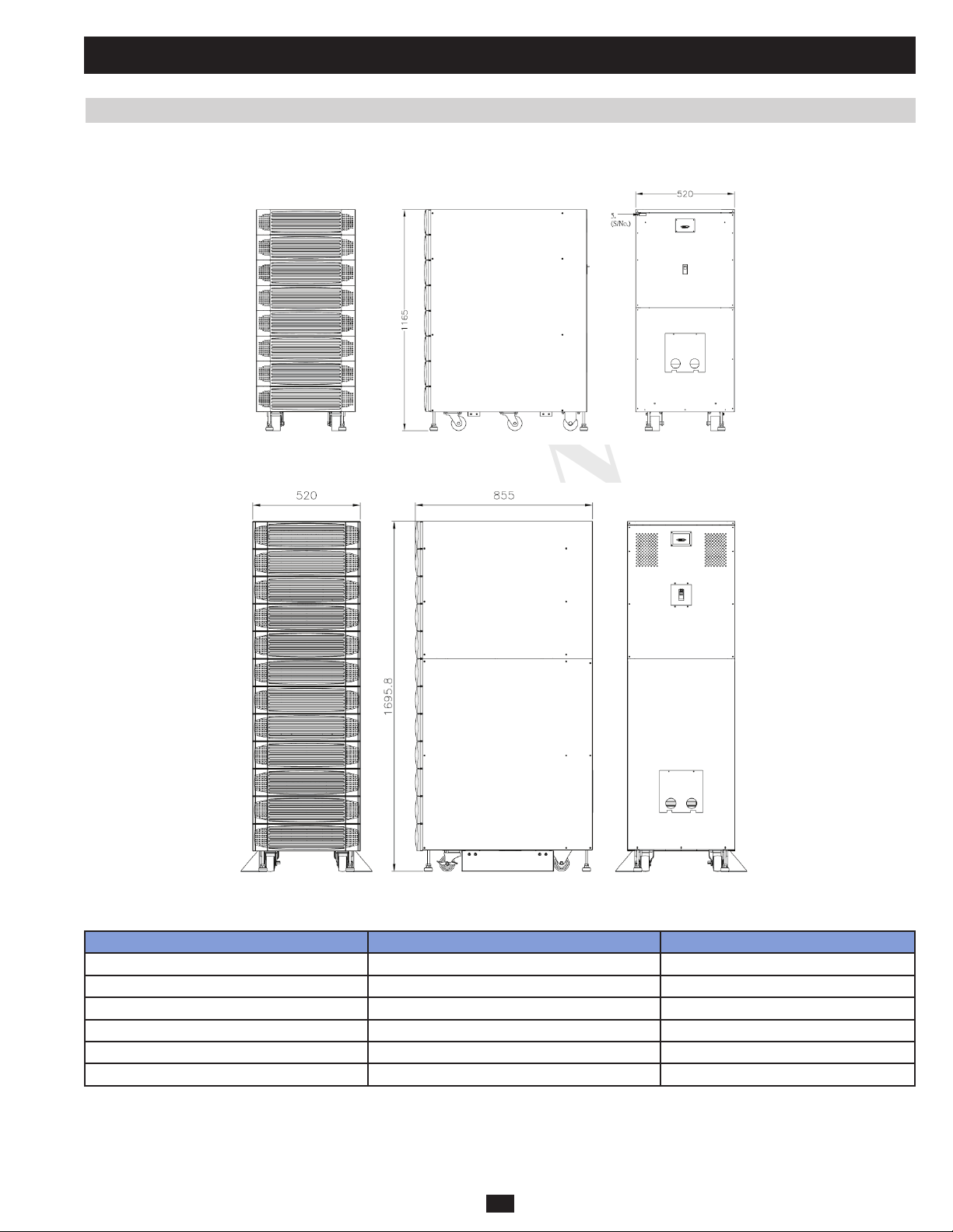
4 Internal Battery (continued)
4.2 Battery Cabinet
The standard battery cabinet includes two models: BP480V26B (Figure 4.2a) and BP480V40C (Figure 4.2b). (See Table 4.2a for battery cabinet
weight and fl oor loading)
Fig 4.2a BP480V26B
PRELIMINARY
Fig 4.2b BP480V40C
Table 4.2a
BP480V26B BP480V40C
Weight
Floor Loading
Battery Capacity
Voltage
Amp/Hour
Battery Type
470 kg 700 kg
1064 kg/m^2 1575 kg/m^2
40 40
12V DC 12 V DC
26AH 40AH
VRLA VRLA
95
Page 78
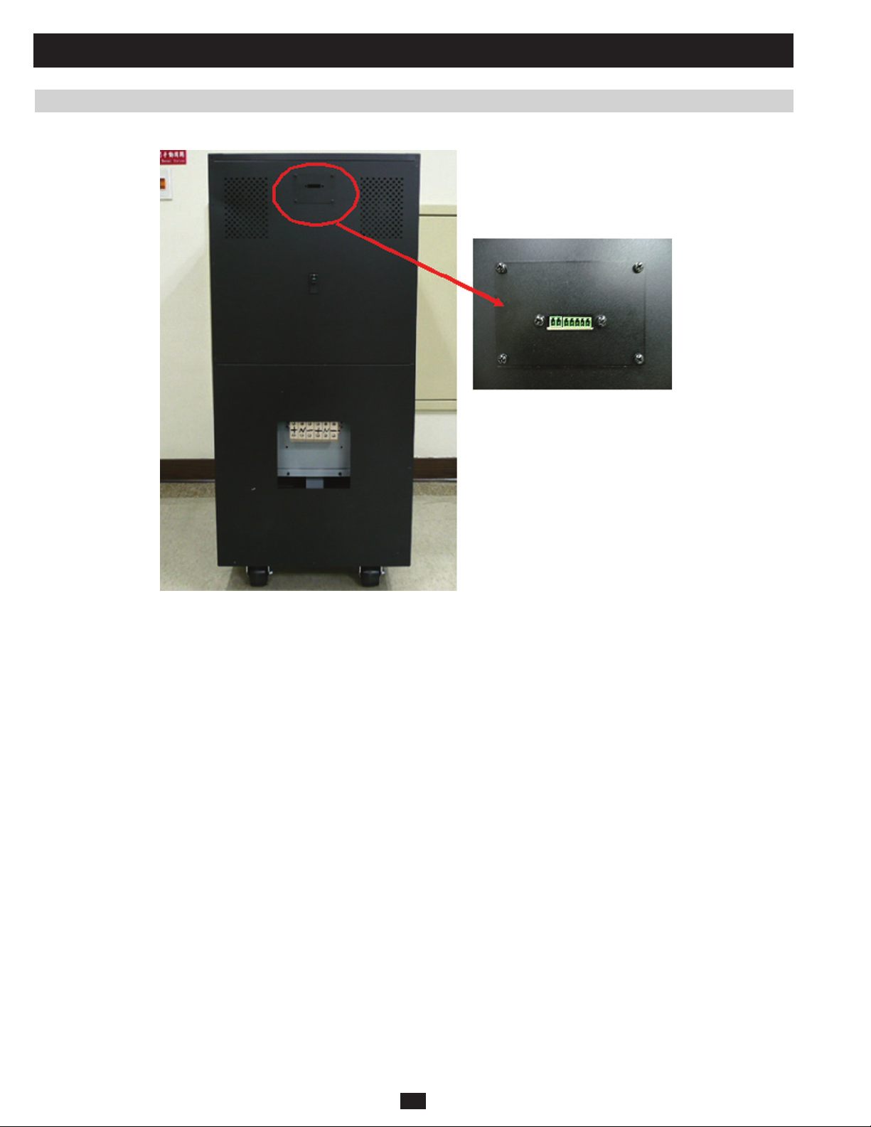
4 Internal Battery (continued)
4.2 Battery Cabinet (continued)
Both battery cabinet models have a Q board installed on the rear (Figure 4.2c).
PRELIMINARY
Q board functions include:
• Battery temperature detection: The UPS detects the temperature of the battery cabinet and compensates the battery voltage.
• Battery circuit breaker status detection: When this breaker is tripped, the UPS can detect its status and display an alarm message on the LCD.
Fig 4.2c
96
Page 79
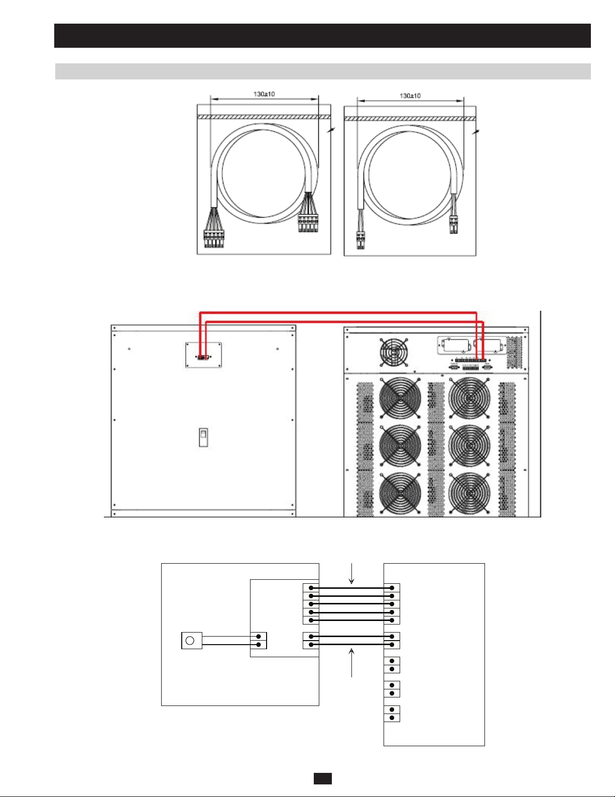
4 Internal Battery (continued)
4.2 Battery Cabinet (continued)
Fig 4.2d W1 and W2 Cables
To connect the external battery cabinet to its UPS system, use the W1 and W2 cables (Figure 4.2d) to connect the Q boards (Figure 4.2e) using the
ports illustrated (Figure 4.2f).
PRELIMINARY
Fig 4.2e Connection between UPS and Battery Cabinet
Q board
Temperature
sensor
Battery Cabinet (for standard B/C type)
1
2
3
4
5
W1
W2
P7
1
2
3
4
5
P6
P5
P4
P3
Fig 4.2f Wiring between UPS and Battery Cabinet
97
UPS
Page 80

5 Troubleshooting
5.1 Alarm Messages
Alarm messages are displayed on the LCD control panel. Press the “UP” and “DOWN” buttons to scroll through all alarm messages.
Table 5.1a Warning Message List
Warning Message Condition Chapter Index
MAIN VOLT/FREQ NOK Main input voltage abnormal
MAIN SEQUENCE NOK Main input phase sequence abnormal 5.2.2
BYPASS VOLT/REQ NOK Bypass voltage over rating
BYPASS SEQUENCE NOK Bypass phase sequence abnormal 5.2.4
BYPASS STATIC SWITCH OVER TEMPERATURE Bypass STS temperature over 80 degree C 5.2.5
BYPASS STATIC SWITCH FAULT Bypass STS open/short 5.2.6
BYPASS STATIC SWITCH OVERLOAD Bypass loading over 175% 5.2.7
UPS INTERNAL COMM ABNORMAL 1.CAN BUS loss
BAT TEST FAIL Battery Capacity too low 5.2.9
BAT OVER CHARGE Battery voltage more than 296V 5.2.10
BATTERY BAD Battery Voltage under 190V 5.2.11
BYPASS FAN FAILURE Bypass FanA/B/C fail 5.2.12
TRANSFORMER OVERHEAT IN/OUT transformer overheat warning (HW detect signal) 5.2.13
UPS OUTPUT VOLT NOK UPS output voltage over rating
UPS EXT PARALLEL COMM ABNORMAL Parallel CAN BUS loss 5.2.15
PARALLEL FAILURE PID confl ict or system KVA rating not the same 5.2.16
REDUNDANCY LOSS UPS lost redundancy 5.2.17
MANUAL BYPASS ON Manual bypass on
BAT LOW WARNING Battery voltage under 220V and above 200V
BAT LOW SHUTDOWN Battery voltage under 200V
BAT REPLACE REQUIRED Battery package out of date
INVERTER OVERLOAD WARNING Loading over 105%
INVERTER OVERLOAD SHUTDOWN Loading over 105%~125% 10min.
INVERTER OVER CURRENT Output current over 80A/phase
EMERGENCY POWER OFF ACTIVED E.P.O./ Remote E.P.O. ON
OUTPUT BREAKER OFF Output breaker not turn on
BYPASS LOAD OVER 104% the load over 104% when UPS is on bypass
BAT CABINET OVER TEMPERATURE Battery cabinet over 35 degree C
EXT BAT BREAKER OFF If support external battery and the breaker ont turn on
PRELIMINARY
( load<70%: 120V~276V, load>70%:173V~276V )
Main input Freq. abnormal ( 45Hz~65Hz )
( 220V/230V/240V ) +/-15%
Bypass Freq. over rating ( 50Hz/60Hz )+/-5Hz
2.SCI loss
3.Power module internal communication loss
( 220V/230V/240V ) +/-10V
Loading over 125%~150% 1min.
Loading over 150% 1sec.
5.2.1
5.2.3
5.2.8
5.2.14
98
Page 81

5 Troubleshooting (continued)
5.1 Alarm Messages (continued)
Alarm messages are displayed on the LCD control panel. Press the “UP” and “DOWN” buttons to scroll through all alarm messages.
Table 5.1b Power Module Warning Message List
Warning Message Condition
PWR MODULE #n PFC FUSE OPEN Power module #n main input fuse broken
PWR MODULE #n INVERTER FUSE OPEN Power module #n output fuse broken
PWR MODULE #n GENERAL FAULT PFC/INV control board fail
PWR MODULE #n CHARGER FAILURE Power module #n charger board fail
PWR MODULE #n FAN FAILURE Power module #n fan(s) fail
PWR MODULE #n PFC OVER TEMPERATURE WARNING Power module #n PFC temperature over 60 degree C
PWR MODULE #n PFC OVER TEMPERATURE SHUTDOWN Power module #n PFC temperature over 65 degree C
PWR MODULE #n INVERTER WARNING OVER TEMPERATURE Power module #n INV temperature over 60 degree C
PWR MODULE #n INVERTER SHUTDOWN OVER TEMPERATURE Power module #n INV temperature over 65 degree C
PWR MODULE #n INVERTER VOLT NOK Power module #n INV voltage over rating ( 220V/230V/240V ) +/-1%
PWR MODULE #n INVERTER SHORT CIRCUIT UPS output short circuit
PWR MODULE #n STATIC SWITCH FAULT Power module #n STS open/short
PWR MODULE #n DC BUS ABNORMAL Power module #n DC BUS over 430V / under 300V
Note: #n indicates the ID of the power module. (Ex.: #1 is power module 1)
Note: In the event of power module failure, refer to chapter 6.1.
PRELIMINARY
99
Page 82

5 Troubleshooting (continued)
5.2 Troubleshooting Flow Charts
5.2.1 “MAIN VOLT/FREQ NOK”
Start
Is the main
input circuit breaker
(Q1) turned on?
Y
Are the
actual value and LCD
value the same ?
Y
Is the main input
voltage or frequency
out of range?
N
Check the EEPROM
voltage setting
N
N
(2)
Turn on the main
input circuit breaker
Y
Is the LCD value zero ?
N
Replace P board or M
Calibrate parameter on
board
EEPROM
(3)
(2 )
END
Fix the connection
N
Y
Is the Wire #1
connection OK?
Y
(1)
PRELIMINARY
END
Fig 5.2.1a
Note (1): For SU20KX, SU40KX and SU40K models, wire #1 is connected between the P board (CNP7) and FA (CNA9) for main input. (See chap-
ter 1.5.) For SU60KX, SU80KX, SU60K, SU80K, SU60KTV and SU80KTV, wire #1 is connected between the P board (CNP7) and F1 (CNF15) for
main input. (See section 1.5.)
Note (2): To learn about EEPROM parameter settings and calibration, turn to section 3.2.
Note (3): For the location of the NHS-SYS-P and NHS-SYS-M boards, turn to section 1.5. To replace the NHS-SYS-M board, simply remove the
EEPROM chip from an old NHS-SYS-M board and insert it into the new one.
M
P
Fig 5.2.1b
100
Page 83

5 Troubleshooting (continued)
5.2 Troubleshooting Flow Charts (continued)
5.2.2 “MAIN SEQUENCE NOK”
This may occur during startup or if the customer changes their charger generation or main input source improperly.
Start
Is the main
input external wiring
correct?
Y
Is the main
input phase sequence
correct?
Y
END
N
N
Fig 5.2.2a
Correct the wiring
Correct phase
rotation
PRELIMINARY
101
Page 84

5 Troubleshooting (continued)
5.2 Troubleshooting Flow Charts (continued)
5.2.3 “BYPASS VOLT/FREQ NOK”
Start
Are the
the main or bypass
input circuit breaker
(Q1 and Q2)
turned on?
Y
Are the
actual value and LCD
value the same ?
Y
Is the main input
voltage or frequency
out of range?
N
Check the EEPROM
PRELIMINARY
voltage setting
N
Turn on the main or
bypass input
circuit breaker
N
Y
(2)
Is the LCD value zero ?
N
Replace P board or M
Calibrate parameter on
board
EEPROM
(3)
(2 )
Y
END
Fix the connection
N
Is the Wire #11
connection OK?
Y
(1)
END
Fig 5.2.3a
Note (1): For SU20KX, SU40KX and SU40K models, wire #11 is connected between P board (CNP8) and FA (CNA9) for bypass input. (See chapter
1.5.) For SU60KX, SU80KX, SU60K, SU80K, SU60KTV and SU80KTV, wire #11 is connected between P board (CNP8) and F1 (CNF15) for bypass
input. (For locations, see chapter 1.7)
Note (2): To learn about EEPROM parameter settings and calibration, turn to chapter 3.2.
Note (3): For the location of the NHS-SYS-P and NHS-SYS-M boards, turn to chapter 1.5. To replace the NHS-SYS-M board, simply remove the
EEPROM chip from an old NHS-SYS-M board and insert it into the new one.
M
P
Fig 5.2.3b
102
Page 85
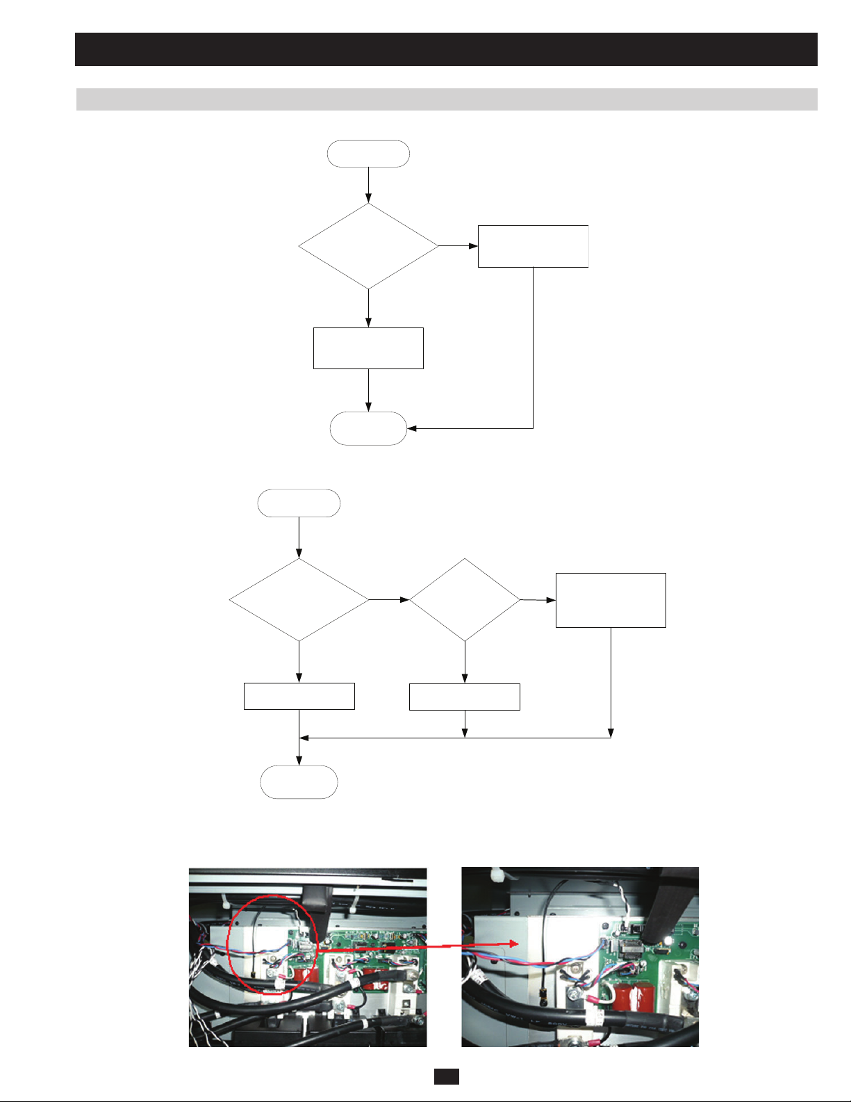
5 Troubleshooting (continued)
5.2 Troubleshooting Flow Charts (continued)
5.2.4 “BYPASS SEQUENCE NOK”
Start
Is the bypass
input external wiring
correct?
Y
Is the bypass input
source phase correct?
END
5.2.5 “BYPASS STATIC SWITCH OVER TEMPERATURE”
Start
PRELIMINARY
Is the UPS loading
too high?
N
N
Fig 5.2.4a
Have the
(1)
fans
Correct the wiring
failed?
Temperature sensing
N
circuit has failed.
Replace the NTC
(2)
Y
Reduce loading
END
Note (1): The fans are installed at the heat-sink of the bypass static switch. (See section 1.5)
Note (2): The NTC is mounted on the heat-sink of bypass static switch (Figure 5.2.5b). Remove wire #35 and unscrew the NTC.
Y
Replace the fan
Fig 5.2.5a
Fig 5.2.5b
103
Page 86
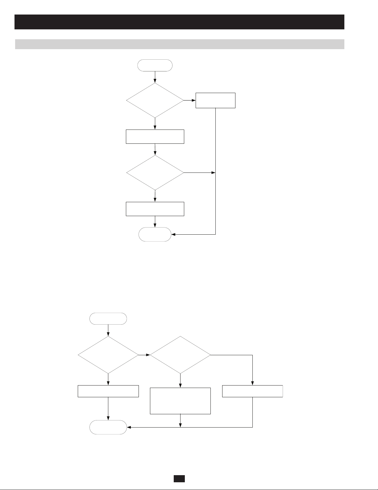
5 Troubleshooting (continued)
5.2 Troubleshooting Flow Charts (continued)
5.2.6 “BYPASS STATIC SWITCH FAULT”
Start
Are the
bypass SCRs
functioning?
Y
Replace the M board
Does the
fault still occur w/ UPS
in bypass mode?
Y
Replace the S or SA board
Note (1): Use a multimeter to measure the pins of bypass SCRs. If the ohm value is close to zero, it indicates that the SCR has failed. (For the
location of bypass SCRs, turn to section 1.5)
Note (2): For the location of the NHS-SYS-M board, turn to section 1.5. To replace the NHS-SYS-M board, remove the EEPROM chip from the old
NHS-SYS-M board and insert it into the new one.
Note (3): For the location of the NHS-SYS-S board (for 60kVA and 80kVA) or the NHS-SYS-SA board (for 20kVA and 40kVA), turn to section 1.5.
PRELIMINARY
(1)
END
Fig 5.2.6a
N
Replace the SCR
(2 )
N
(3)
5.2.7 “BYPASS STATIC SWITCH OVERLOAD”
Start
Is the UPS loading
too high?
YY
Reduce loading
END
Note (1): Use a multimeter to measure OIP CT resistance. If the value is about 35ohm, the OIP CT is good.
Note (2): To learn about EEPROM parameter settings and calibration, turn to section 3.2.
Note (3): To learn the location of the NHS-SYS-P and NHS-SYS-M boards, turn to section 1.5. To replace the NHS-SYS-M board, remove the
EEPROM chip from the old NHS-SYS-M board and insert it into the new one.
N
Is the load CT
functioning?
Replace P board or M
board
Calibrate parameter on
EEPROM
Fig 5.2.7a
(1)
(3)
(2)
104
N
Replace CT
Page 87

5 Troubleshooting (continued)
5.2 Troubleshooting Flow Charts (continued)
5.2.8 “UPS INTERNAL COMM ABNORMAL”
Start
Has the
communication wire
Re-insert communication
wire and try again
slipped ?
Y
END
(1)
N
Remove power connection
of power module #1
Still getting the
same fault message?
N
Replace the power module
(2)
Re-insert power connection
of previous power module
and remove the next power
module’s connection
Y
Fig 5.2.8a
Note (1): Check W2A, W2B, W2C, W2D, W4A, W4B and W6 (Fig 5.2.8b).
Note (2): Remove wires W61A, W65A and W68A.
PRELIMINARY
W61A
W62B
W63C
W64D
W65A
W66B
W67C
W36D
W2A
W5
W5
W5
W5
W5
W5
W2B
Fig 5.2.8b
105
W3A
W4A
W6
W2B
W6
W6
W2C
W6
W6
W2D
W6
W4B
W68A
W69B
W70C
W71D
Page 88

5 Troubleshooting (continued)
5.2 Troubleshooting Flow Charts (continued)
5.2.9 “BATTERY TEST FAIL”
Start
Are the
actual value
and LCD value the
same ?
Y
Battery voltage < +/-256Vdc
Check battery bank and
consider replacing the
battery
END
Note (1): To learn about EEPROM parameter settings and calibration, turn to section 3.2.
Note (2): For the location of the NH-SYS-P and/or NH-SYS-M board, turn to section 1.5. To replace the NHS-SYS-M board, remove the EEPROM
chip from the old NHS-SYS-M board and insert it into the new one.
5.2.10 “BATTERY OVER CHARGE”
Start
N
Fig 5.2.9a
Replace P board or M
Calibrate parameter
on EEPROM
board
(2)
(1)
PRELIMINARY
neutral (N) of the battery
Is the
external wiring
correct ?
(1)
N
Correct the wiring
Y
Are the
actual value and LCD
value the same ?
Y
Is every power module
charge voltage about 274V?
END
Note (1): The midpoint of the battery string must be connected to the neutral (N) of the battery terminal block.
Note (2): To learn about EEPROM parameter settings and calibration, turn to section 3.2.
Note (3): For the location of the NH-SYS-P and/or NH-SYS-M board, turn to section 1.5. To replace the NHS-SYS-M board, remove the EEPROM
chip from the old NHS-SYS-M board and insert it into the new one.
Note (4): Check the battery voltage of each power module one at a time. If it is normal, check the next one.
(4)
Fig 5.2.10a
Replace P board or M
N
Calibrate parameter
on EEPROM
106
board
(3)
(2)
Page 89

5 Troubleshooting (continued)
5.2 Troubleshooting Flow Charts (continued)
5.2.11 “BATTERY BAD”
Start
Is
the battery
circuit breaker
turned on ?
Y
Is the external
wiring correct?
Y
Are the
actual value
and LCD value the
same ?
Y
N
PRELIMINARY
Battery broken
Replace battery
N
N
LCD value zero?
Replace P board or M
Calibrate parameter
on EEPROM
Turn on battery
circuit breaker
Correct the wiring
Is the
N
(3)
board
(2)
Fix the connection
N
Y
Is the Wire #31
connection OK?
Y
Check the fuse of
external battery or
internal battery
(1)
END
Fig 5.2.11a
Note (1): Wire #31 connects CNP10 on the NH-SYS-P board to CNB7 on the NH-SYS-B board (Figure 5.2.11b).
Note (2): To learn about EEPROM parameter settings and calibration, turn to section 3.2.
Note (3): For the location of the NH-SYS-P and/or NH-SYS-M board, turn to section 1.5. To replace the NHS-SYS-M board, remove the EEPROM
chip from the old NHS-SYS-M board and insert it into the new one.
Fig 5.2.11b
107
Page 90

5 Troubleshooting (continued)
5.2 Troubleshooting Flow Charts (continued)
5.2.12 “BYPASS FAN FAILURE”
in bypass mode?
fan A spinning?
Start
Is the UPS
Y
Is
Y
N
Replace the P board or
N
Is
fan C spinning?
Y
M board
fan B spinning?
Fan A failed
Replace fan A
(1)
Is
Y
(2 )
N
NY
N
Fan C failed
Replace fan C
Does fan C
work normally after
restarting UPS?
Fan A and B failed
Replace fan A and
fan B
(4)
(2)
(3)
PRELIMINARY
Note (1): For the location of the NH-SYS-P and/or NH-SYS-M board, turn to section 1.5. To replace the NHS-SYS-M board, remove the EEPROM
chip from the old NHS-SYS-M board and insert it into the new one.
Note (2): Fan A is the main fan for the bypass static switch (Figure 5.2.12b).
Note (3): Fan B is the redundancy fan for the bypass static switch (Figure 5-16).
Note (4): Fan C is the main fan for the fi lter (Figure 5.2.12c).
Replace the S board
or M board
(1)
END
N
Do fans
work normally after
restarting UPS?
Y
Fig 5.2.12a
Fig 5.2.12b Fig 5.2.12c
108
Page 91

5 Troubleshooting (continued)
5.2 Troubleshooting Flow Charts (continued)
5.2.13 “TRANSFORMER OVERHEAT”
Start
Is the UPS loading
too high?
Y
Reduce loading
END
Note (1): Models with C–cabinets are: SU40K, SU60K, SU80K, SU60KTV and SU80KTV.
Note (2): See Figure 5.2.13b for location.
PRELIMINARY
Note (3): For the location of the NH-SYS-M board, turn to section 1.5. To replace the NHS-SYS-M board, remove the EEPROM chip from the old
NHS-SYS-M board and insert it into the new one.
N
Is it a
C-Cabinet model ?
YY
Are the
W38 plug in CNM11
and W39 plug in
CNM10?
Plug in these w ires
(2)
Fig 5.2.13a
N
(1 )
Are short-pins
in CNM10 and
CNM11?
Replace M board
(2)
N
Plug in short-pins
(3)
Fig 5.2.13b
109
Page 92
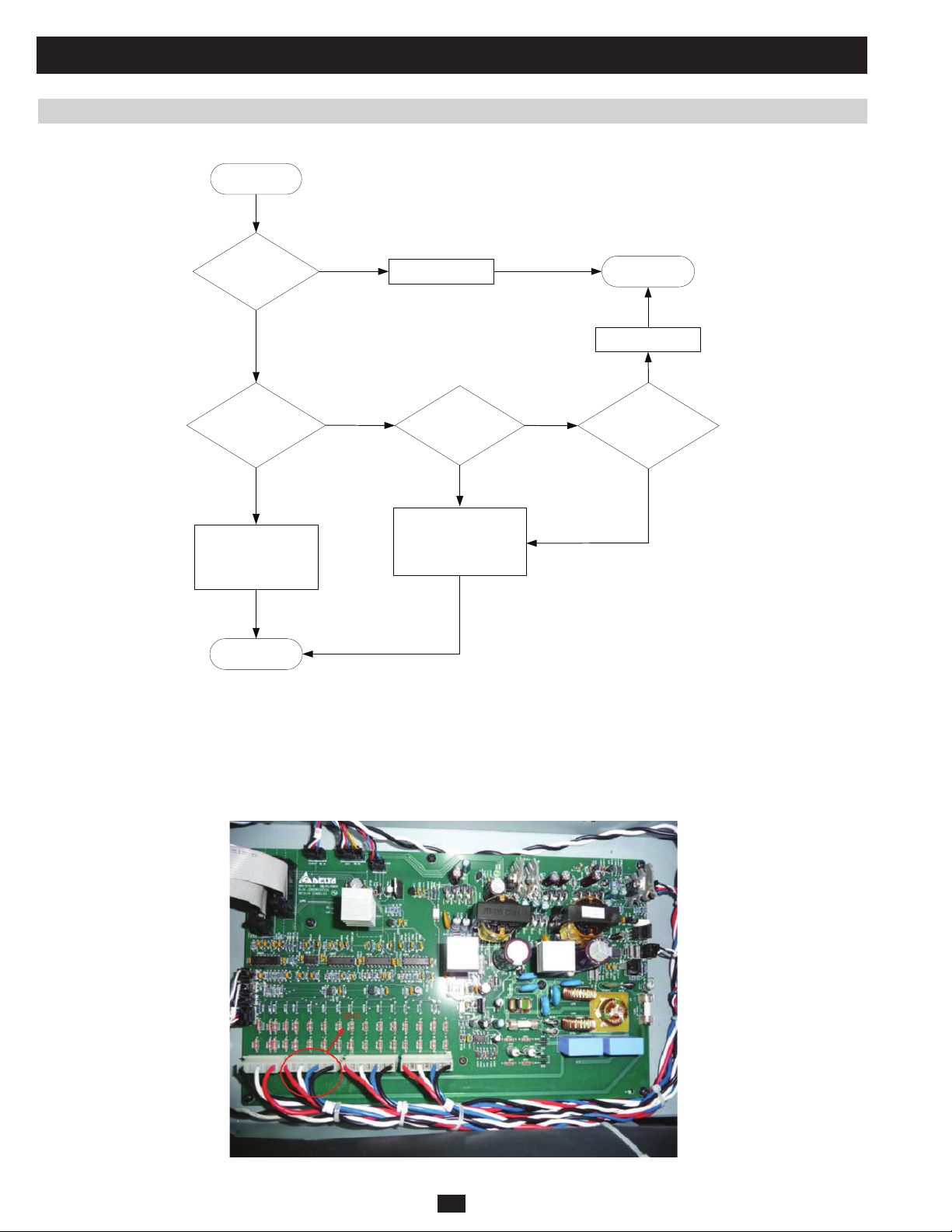
5 Troubleshooting (continued)
5.2 Troubleshooting Flow Charts (continued)
5.2.14 “PS OUTPUT VOLT NOK”
Start
Is the output
wire connection
OK?
Y
Are the
Actual value
and LCD value
the same ?
Y
Check if any power
module output voltages
are out of range
PRELIMINARY
END
(4)
N
N
Fix the connection
Is the
LCD value
zero?
N
Replace P board or M
Calibrate parameter on
Fig 5.2.14a
board
EEPROM
(3)
(2)
END
Fix the connection
N
Is the
Y
Wire #10
connection
(1)
OK?
Y
Note (1): Wire #10 connects CNP9 on the NH-SYS-P board with CNFC20 on the NH-SYS-FC board (Figure 5.2.14b).
Note (2): To learn about EEPROM parameter setting and calibration, refer to section 3.2.
Note (3): For the location of the NH-SYS-P board and NH-SYS-M boards, turn to section 1.5. To replace the NHS-SYS-M board, remove the
EEPROM chip from the old NHS-SYS-M board and insert it into the new one.
Note (4): Check the output voltage of each power module one at a time. If normal, check the next power module.
Fig 5.2.14b
110
Page 93
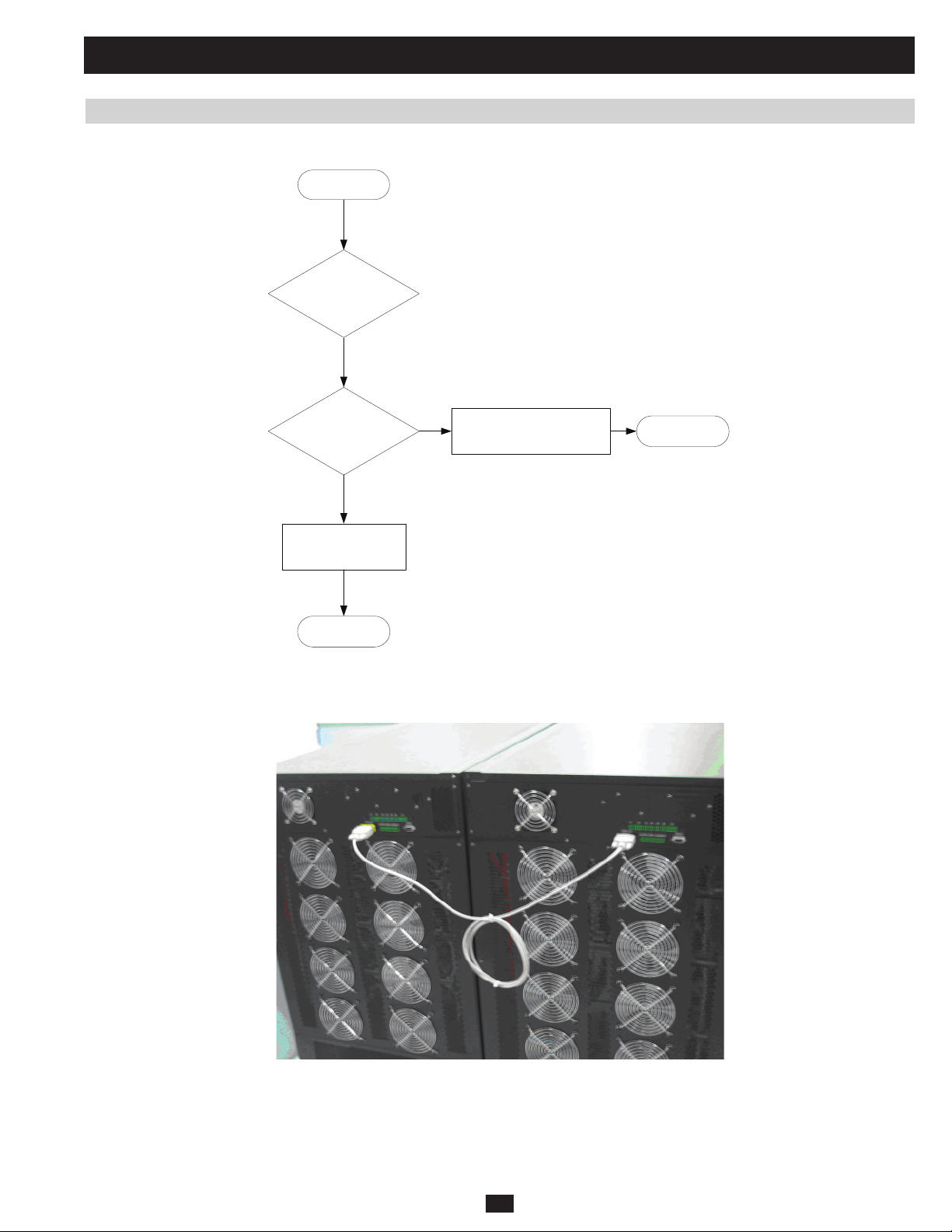
5 Troubleshooting (continued)
5.2 Troubleshooting Flow Charts (continued)
5.2.15 “PS EXT PARALLEL COMM ABNORMAL”
Start
Check
firmware first,
follow firmware
procedure
Has the
parallel wire
Re-insert the parallel
wire and try again
slipped?
Y
END
(1 )
PRELIMINARY
Note (1): The external parallel wire is located on the rear panel (Figure 5.2.15b).
N
Parallel communication failed
Replace the R board
Fig 5.2.15a
END
Fig 5.2.15b
111
Page 94

5 Troubleshooting (continued)
5.2 Troubleshooting Flow Charts (continued)
5.2.16 “PARALLEL FAILURE”
Start
Are both
system’s EEPROM
power rating settings
the same?
Y
Make sure that parallel
(2)
IDs are different
Note (1): Figure 5.2.16b shows the EEPROM’s power rating settings (Rating VA). To learn about EEPROM parameter settings, turn to section 3.2.
Note (2): Access parallel ID settings using the LCD control panel (bypass mode only). (UPS SETUP
(1 )
END
Fig 5.2.16a
Make sure the units
N
Synchronize power
are identical.
rating settings
(1)
LOCAL SETUP PARALLEL ID)
PRELIMINARY
Fig 5.2.16b
112
Page 95

5 Troubleshooting (continued)
5.2 Troubleshooting Flow Charts (continued)
5.2.17 “REDUNDANCY LOSS”
Start
Is the redundancy
setting correct
Y
Reduce loading
END
Note (1): Access the redundancy setting using the LCD control panel (only in bypass mode). (UPS SETUP
Select the power module’s redundancy number.
EX: 40kVA UPS, load < 20kVA, redundancy number =1.
If one power module proves abnormal, another power module will continue to supply the load without interruption.
40kVA UPS, load > 20kVA, redundancy number =1.
LCD panel displays “REDUNDANCY LOSS” message.
If one power module is abnormal, another power module will be overloaded and shut down to bypass.
(1)
N
Fig 5.2.17a
Reset redundancy
number
REDUNDANCY SETUP)
PRELIMINARY
113
Page 96

6 Power Module
6.1 Failure Power Module Identify
WARNING: Before opening the unit, please make sure that the UPS is in Manual Bypass mode so that it
continues to supply power to the critical load (the critical load is supported directly by utility power).
These instructions will help you diagnose which power modules have failed and which are protected.
1) Check the warning messages by pressing the “ ” or “ ” button on the main page of the control panel. (Figure 6.1a) (Table 5.1b lists the
conditions for each power module warning message)
2) Check the event log message. (Figure 6.1b) (Maintenance Event Log Read)
1#ELUDOMRWP
●
●
◆
◆
Fig 6.1a
1#ELUDOMRWP
NEPOESUFCFP
NEPOESUFCFP
FFO1#ELUDDOMRWP
FFO1#ELUDDOMRWP
DERIUQERECIVRES
DERIUQERECIVRES
E
R
U
SAEM
E
R
U
SAEM
T
E
S
SPU
SPU
T
E
S
E
T
NIAM
E
T
NIAM
ECNPAUN
ECNPAUN
PRELIMINARY
ECNANETNIAM
ECNANETNIAM
CITSITATS
CITSITATS
GOLTNEVE
DAER
DAER
ESARE
ESARE
GOLTNEVE
TSET&PUTESLAUNAM
TSET&PUTESLAUNAM
EDARGPUERAWMRIF
EDARGPUERAWMRIF
SREHTO
SREHTO
GOLTNEVE
GOLTNEVE
EVENTㅤLOG
EVENTㅤLOG
07-07-03ㅤ13:17:00
07-07-03ㅤ13:17:00
ㅤUPSㅤState:LoadㅤonㅤInverter
ㅤUPSㅤState:LoadㅤonㅤInverter
07-07-03ㅤ13:15:57
07-07-03ㅤ13:15:57
ㅤInputㅤVoltageㅤNormal
ㅤInputㅤVoltageㅤNormal
07-07-03ㅤ13:15:57
07-07-03ㅤ13:15:57
ㅤInputㅤFrequencyㅤNormal
ㅤInputㅤFrequencyㅤNormal
07-07-02ㅤ13:15:54
07-07-02ㅤ13:15:54
ㅤUPSㅤState:ㅤLoadㅤonㅤBypass
ㅤUPSㅤState:ㅤLoadㅤonㅤBypass
07-07-02ㅤ13:15:53
07-07-02ㅤ13:15:53
ㅤInputㅤFrequencyㅤAbnormal
ㅤInputㅤFrequencyㅤAbnormal
07-07-02ㅤ13:10:16
07-07-02ㅤ13:10:16
ㅤInputㅤVoltageㅤAbnormal
ㅤInputㅤVoltageㅤAbnormal
Fig 6.1b
114
Page 97

6 Power Module (continued)
6.1 Failure Power Module Identify (continued)
3) Check the information of DC BUS voltage. (Figure 6.1c) (Maintenance Others Module DC BUS volt Administrator) Normally,
the DC BUS voltage of a power module is about +/- 370Vdc. Use this number to confi rm which power module is abnormal.
4) Check the Output of Power modules. (Figure 6.1d) (Measure
E
R
U
SAEM
SAEM
SPU
SPU
NIAM
NIAM
E
R
U
T
E
S
T
E
S
E
T
E
T
SREHTO
SREHTO
ECNPAUN
ECNPAUN
ECNANETNIAM
ECNANETNIAM
CITSITATS
CITSITATS
GOLTNEVE
GOLTNEVE
EDARGPUERAWMRIF
EDARGPUERAWMRIF
press “ ” or “ ” button to choose)
TSET&PUTESLAUNAM
TSET&PUTESLAUNAM
SREHTO
SREHTO
NOISREVWF&NS
NOISREVWF&NS
EMITMETSYS
PRELIMINARY
NIGOL
NIGOL
IMDA
IMDA
RESU
RESU
EMITMETSYS
TLOVSUBCDELUDOM
TLOVSUBCDELUDOM
E
R
U
SAEM
ROTARTSIN
ROTARTSIN
EGATLOVSUBCD
EGATLOVSUBCD
V4.863-/V6.273+:1#
V4.863-/V6.273+:1#
V4.863-/V6.273+:2#
V4.863-/V6.273+:2#
V4.863-/V6.273+:3#
V4.863-/V6.273+:3#
V4.863-/V6.273+:4#
V4.863-/V6.273+:4#
SAEM
SPU
SPU
NIAM
NIAM
REWOP
REWOP
REVNI
REVNI
0.05
0.05
E
R
U
T
E
S
T
E
S
E
T
E
T
O
M
O
M
R
E
T
R
E
T
0
.
0
0
.
0
YCNEUQERF
YCNEUQERF
z
H
z
H
ECNPAUN
ECNPAUN
3
L
UVD
L
UVD
O
O
/
/
#
3
#
T
U
TEU
TEU
T
U
5
.
2P1
2P1
A22:R
5
.
A22:R
A5.21/V0.022:S
A5.21/V0.022:S
A5.21/V0.022:T
A5.21/V0.022:T
Fig 6.1c Fig 6.1d
115
Page 98
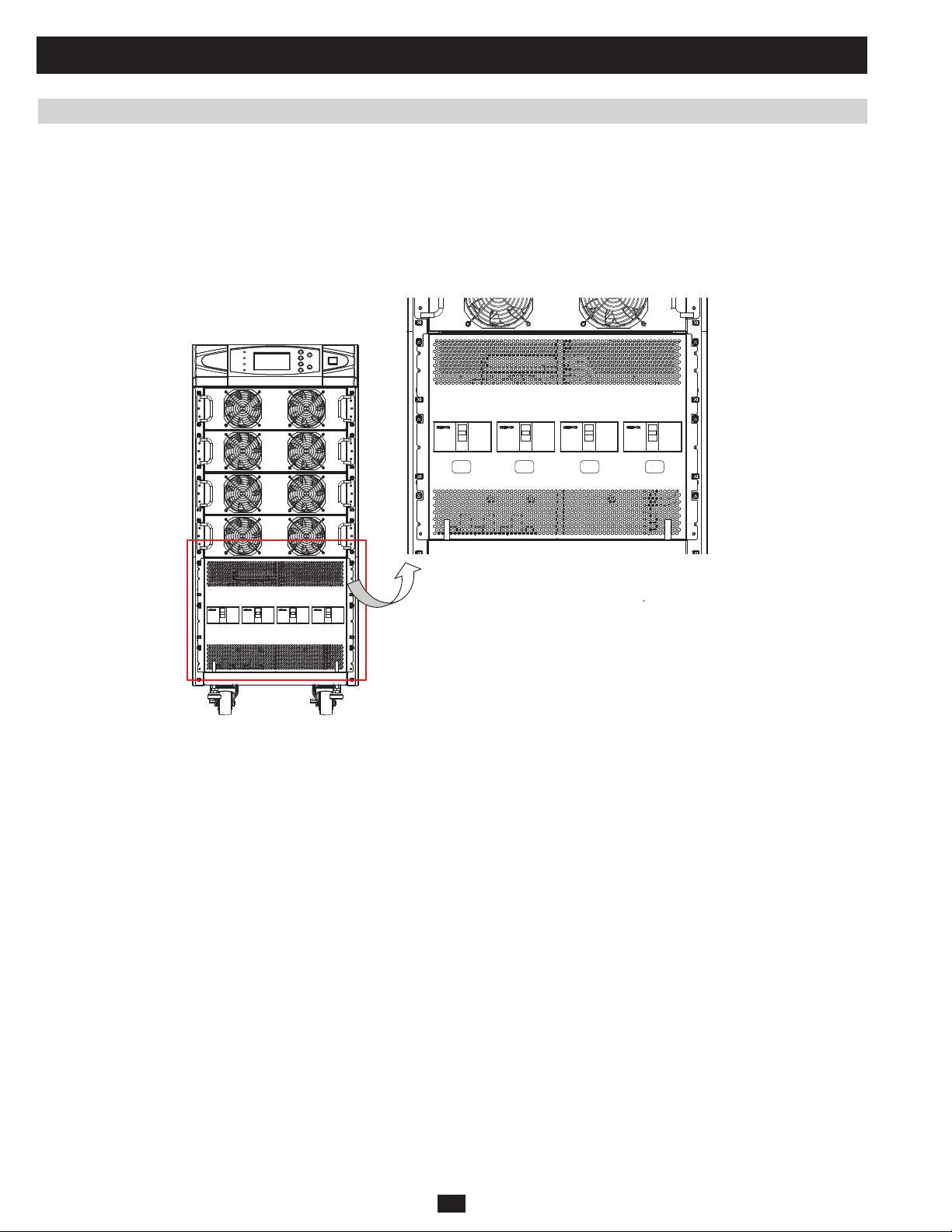
6 Power Module (continued)
6.1 Failure Power Module Identify (continued)
5) (Use this step to shut down the UPS with load protection)
Set UPS to manual bypass mode.
If the UPS is on normal mode, press the “OFF” button to enter bypass mode. Then turn on the manual bypass circuit breaker (Q3) and turn off the
output circuit breaker (Q4). (Figure 6.1e)
Next, turn off the main input circuit breaker (Q1) so that the power module discharges its DC BUS voltage. Monitor the power module’s output
(Figure 6.1d) and DC BUS voltage (Figure 6.1c) using the LCD panel.
These voltages will decrease gradually within each normal power module.
Q4 Q3 Q2 Q1
Output
Q1: Input Circuit Breaker
Q2: Bypass Input Circuit Breaker
Q3: Manual Bypass Circuit Breaker
PRELIMINARY
Ultimately, normal power modules will shut down (with fans inactive), while faulty power modules will still be pending (no discharge, fans still
active).
Finally, turn off the battery switch to force the power modules to shut down. At this point, faulty power modules have either failed or are being
protected.
6) Turn on the main input circuit breaker. Then, once the fan is active, turn off the main input circuit breaker. Normal power modules will shut
down instantly, while faulty power module will discharge DC BUS voltage.
Failed power modules can be identifi ed by the following:
• Inactive fans
• Alarm message on LCD
If neither of these occur, follow step 7 to ascertain that the faulty power modules are protected.
7) Turn on the main input circuit breaker and observe whether the power module’s DC BUS voltage (Figure 6.1c) ever reaches +/- 370Vdc. If it
does not, or you receive an alarm message, the power module has failed.
Turn off the main input circuit breaker and monitor the output message for each power module (Figure 6.1d). If the output voltage is abnormal or
you receive an alarm message, the power module has failed.
Q4: Output Circuit Breaker
Fig 6.1e
Manual
Bypass
Bypass
Input
Main
Input
116
Page 99

6 Power Module (continued)
6.2 Power Module Replacement
WARNING: Before opening the unit, please make sure that the UPS is in Manual Bypass mode so that it
continues to supply power to the critical load (the critical load is supported directly by utility power).
WARNING: Make sure that the UPS unit is shut down completely. (Main Input circuit breaker (Q1), Bypass
Input circuit breaker (Q2) and Output circuit breaker (Q4) must be OFF (see Figure 6.2a).)
Q4 Q3 Q2 Q1
Output
Q1: Input Circuit Breaker
Q2: Bypass Input Circuit Breaker
Q3: Manual Bypass Circuit Breaker
Q4: Output Circuit Breaker
Manual
Bypass
Bypass
Input
Main
Input
PRELIMINARY
Fig 6.2a
To remove the power module:
a) Unscrew the rear panel cover (Figure 6.2b).
Fig 6.2b
117
Page 100

6 Power Module (continued)
6.2 Power Module Replacement (continued)
b) Disconnect the power module (Figures 6.2c and 6.2d).
+12V
Rev.
R
S
T
N
+
N
–
ID Detect
Comm. Port
Comm. Port
N
T
S
R
AC INPUT DC INPUT OUTPUT
Fig 6.2c
W3A
W5
W5
W5
W5
W5
W5
W4A
W6
W2B
W6
W6
W2C
W6
W6
W2D
W6
W4B
W68A
W69B
W70C
W71D
W2A
W61A
W62B
PRELIMINARY
W63C
W64D
W65A
W66B
W67C
W36D
W2B
Fig 6.2d
118
 Loading...