

Page 1

Warranty
Registration:
register online today for a
Owner’s Manual
chance to win a FREE Tripp Lite
product—www.tripplite.com/warranty
Intelligent True On-Line UPS Systems (Rackmount/Tower)
• Includes UPS system with internal battery system (5&6kVA), detachable PDU and detachable
Important Safety Warnings 2
Mounting 3
Features 4
Connection 9
Optional Connection 12
Manual Bypass Operation 14
SmartOnline™
Single-Phase 5kVA–6kVA
parallel PDU modules (6kVA) • Rackmount and tower adaptable
Not suitable for mobile applications.
Operation 15
Internal Battery Replacement 28
Storage and Service 29
Warranty and Warranty Registration 29
Español 30
Français 59
Русский 88
1111 W. 35th Street, Chicago, IL 60609 USA • www.tripplite.com/support
Copyright © 2012 Tripp Lite. All rights reserved. SmartOnline is a trademark of Tripp Lite.
201207113 933070.indb 1 9/17/2012 1:19:41 PM
1
Page 2
Important Safety Warnings
SAVE THESE INSTRUCTIONS. This manual contains important instructions and warnings that should be followed during the
installation and maintenance of this product. Failure to heed these warnings may affect your warranty.
UPS Location Warnings
• Install your UPS in a structurally sound area. Your UPS is extremely heavy; take care when moving and lifting the unit.
• Only operate your UPS at indoor temperatures between 32° F and 104° F (between 0° C and 40° C). For best results,
keep indoor temperatures between 62° F and 84° F (between 17° C and 29° C).
• Leave adequate space around all sides of the UPS for proper ventilation.
• Do not install the UPS near magnetic storage media, as this may result in data corruption.
• Do not mount unit with its front or rear panel facing down (at any angle). Mounting in this manner will seriously
inhibit the unit’s internal cooling, eventually causing product damage not covered under warranty.
UPS Connection Warnings
• Isolate the UPS before working on this
circuit.
• The power supply for this unit must be
single-phase rated in accordance with
the equipment nameplate. It also must
be suitably grounded.
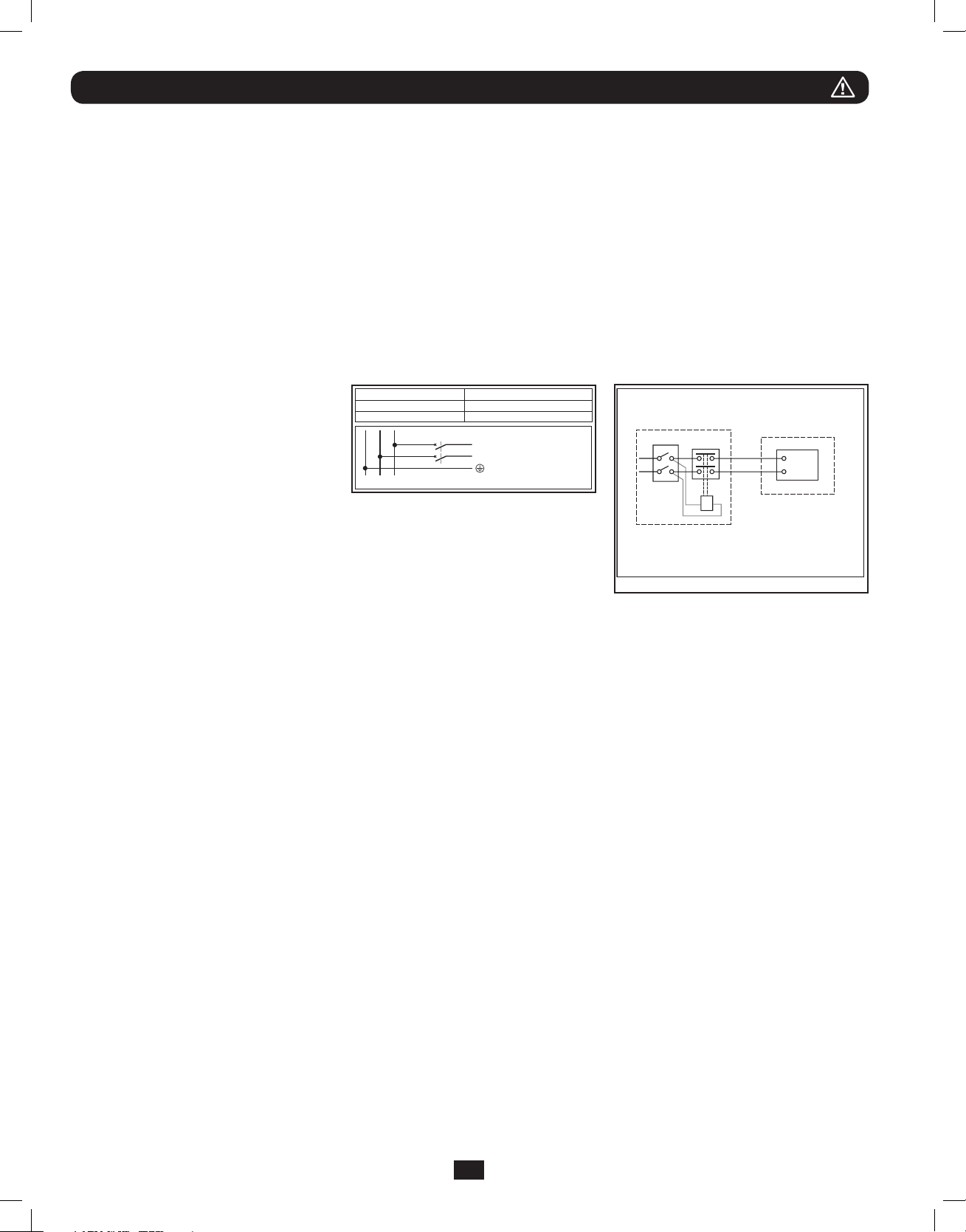
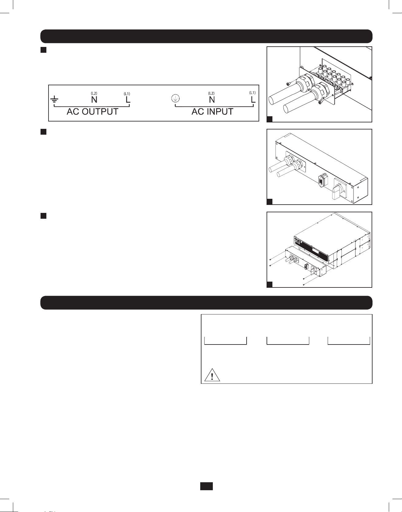
Equipment Connection Warnings
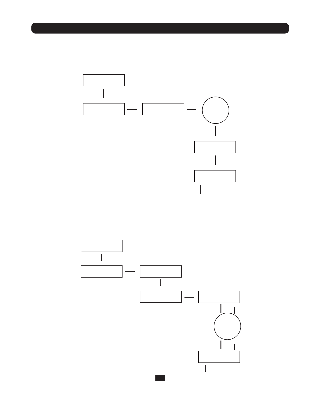
Required Protective Devices and Cable Cross-Sections
Recommended upstream protection
UPS Power Rating Upstream Circuit Breaker
5kVA N/A
6kVAC curve - 40A
2 poles circuit breaker
GL1
L2(N)
L1
L2(N)
To UPS Nor mal AC source
External power
distribution unit
Q
L
N
UPS
T
B
L
N
• Use of this equipment in life support applications where failure of this equipment
can reasonably be expected to cause the failure of the life support equipment or
to significantly affect its safety or effectiveness is not recommended. Do not use
this equipment in the presence of a flammable anesthetic mixture with air, oxygen
or nitrous oxide.
Legend
B—Contactor solenoid.
Q—Mains input thermal-magnetic switch.
T—Two-pole contactor 100 A AC1; coil voltage: according to the mains input.
Remark: Q needs to use the approved component of Safety Certification.
• Connect your UPS power module’s grounding terminal to a grounding electrode conductor.
• The UPS is connected to a DC energy source (battery). The output terminals may be live even when the UPS is not connected
to an AC supply.
Maintenance Warnings
• Your UPS power module and battery module(s) do not require routine maintenance. Do not open them for any reason. There
are no user-serviceable parts inside.
Battery Warnings
• Connect only Tripp Lite battery modules (of the correct type and voltage) to your UPS power module’s external battery
connector.
• Batteries can present a risk of electrical shock and burn from high short-circuit current. Observe proper precautions. Do not
dispose of the batteries in a fire. Do not open the UPS or batteries. Do not short or bridge the battery terminals with any
object. Unplug and turn off the UPS before performing battery replacement. Use tools with insulated handles. There are no
user-serviceable parts inside the UPS. Battery replacement should be performed only by authorized service personnel using the
same number and type of batteries (Sealed Lead-Acid). The batteries are recyclable. Refer to your local codes for disposal
requirements or visit www.tripplite.com/UPSbatteryrecycling for recycling information. Tripp Lite offers a complete line of UPS
System Replacement Battery Cartridges (R.B.C.).Visit Tripp Lite on the Web at www.tripplite.com/support/battery/index.cfm to
locate the specific replacement battery for your UPS.
• Fuses should be replaced only by factory authorized personnel. Blown fuses should be replaced only with fuses of the same
number and type.
• Service and repair should be done only by trained personnel. Prior to any service work performed on hardwired power modules,
they should be turned off or manually bypassed via the transformer. Prior to any service work performed on power modules that
plug directly into wall outlets, they should be turned off and unplugged. Note that potentially lethal voltages exist within this unit
as long as the battery supply is connected.
• Do not connect or disconnect battery module(s) while the UPS is operating from the battery supply or when the transformer
module is not in bypass mode (if your UPS system includes a transformer module with a bypass switch).
• During “hot-swap” battery module replacement your UPS will be unable to provide battery backup in the event of a blackout.
• Only connect compatible battery module(s).
2
201207113 933070.indb 2 9/17/2012 1:19:42 PM
Page 3
Mounting
Mount your equipment in either a 4-post or 2-post rack or rack enclosure. The user must determine the fitness of hardware and
procedures before mounting. If hardware and procedures are not suitable for your application, contact the manufacturer of your
rack or rack enclosure. The procedures described in this manual are for common rack and rack enclosure types and may not be
appropriate for all applications.
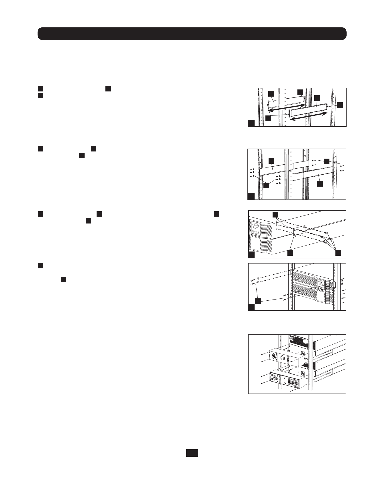
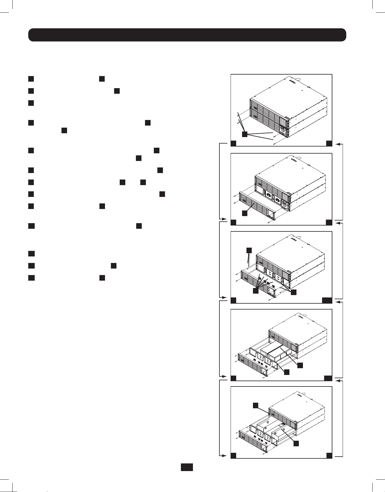
4-Post Mounting
1
The included plastic pegs A will temporarily support the empty rackmount shelves
B
while you install the permanent mounting hardware. Insert a peg near the center of
the front and rear bracket of each shelf as shown. (Each front bracket has 6 holes
and each rear bracket has 3 holes.) The pegs will snap into place.
After installing the pegs, expand each shelf to match the depth of your rack rails. The
pegs will fit through the square holes in the rack rails to support the shelves. Refer to
the rack unit labels to confirm that the shelves are level in all directions. Note: The
support ledge of each shelf must face inward.
2
Secure the shelves B to the mounting rails permanently using the included screws
and cup washers C as shown.
• For 4U equipment mounting, place 6 screws total at the front and 4 screws total
at the back.
Tighten all screws before proceeding.
Warning: Do not attempt to install your equipment until you have inserted and
tightened the required screws. The plastic pegs will not support the weight of
your equipment.
3
Attach mounting ears D to the front mounting holes of your equipment E using
the screws provided F. The ears should face forward.
Note: It is recommended that you remove the internal batteries of the UPS prior to
installation. This will remove excess weight and will allow safer handling of equipment.
See Internal Battery Replacement section for battery removal instructions.
B
A
1
B
C
2
E
3
A
B
C
B
D
A
F
4
Using an assistant, lift your equipment and slide it onto the mounting shelves.
Attach your equipment to the rack by passing the screws, nuts and washers (user-
provided) G through its mounting ears and into the rack rails. Be sure to use separate
rack rails for each individual component.
G
4
12kVA UPS Configuration—SU12KRT4UHW Only (Using 2 6kVA Power Modules)
See manual included with parallel PDU for SU12KRT4UHW Mounting.
SW
SW
14
14
2-Post Mounting (Optional)
To mount your 5kVA or 6kVA UPS in a 2-post rack, you must purchase a Tripp Lite 2-Post Rackmount Installation Kit (model:
2POSTRMKITHD, sold separately) for each power module and battery pack installed. See the Installation Kit’s owner’s manual for
complete mounting instructions.
Note: 2-post mounting is not recommended for 12kVA UPS systems.
3
201207113 933070.indb 3 9/17/2012 1:19:45 PM
Page 4
Mounting
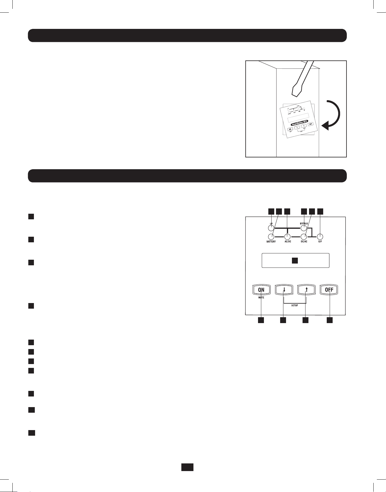
Tower Mounting
To mount the UPS in an upright (tower) position, Tripp Lite’s 2-9USTAND accessory
is required (sold separately).
Once mounted, rotate the power module’s Control Panel for easier viewing while the
UPS is upright. Insert a small screwdriver, or other tool, in the slots on either side of
the Control Panel. Pop the panel out, rotate it, and pop the panel back into place.
Features
Before installing and operating your UPS, familiarize yourself with the location and function of the features of each component.
Power Module Front Panel Controls
11
2
10 79 68
1
3 4 5
LCD DISPLAY: This backlit (16 × 2 character) dot matrix display indicates a wide
1
range of UPS operating conditions and diagnostic data. It also displays UPS
settings and options when the UPS is in setup mode.
ON/MUTE BUTTON: Press this button and hold it until you hear a beep to turn
2
the UPS system’s inverter ON. If the UPS’s battery alarm is sounding, press this
button to silence it.
SCROLL DOWN/EXIT SETUP BUTTON: This button allows you to browse through
3
different options and power readings on the LCD display. Momentarily pressing it
causes the LCD screen to display a different power reading (see “Operation”
section). Pressing it and the SCROLL UP button together puts the UPS in setup
mode, where this button is used to scroll through setup options and to exit setup
mode.
SCROLL UP/SELECT BUTTON: This button allows you to browse through different
4
options and power readings on the LCD display. Momentarily pressing it causes
the LCD screen to display a different power reading (see “Operation” Section).
Pressing it and the SCROLL DOWN button together puts the UPS in setup
mode, where this button is used to select setup options.
OFF BUTTON: Press this button until you hear a beep to turn the UPS system’s inverter OFF.
5
O/P (OUTPUT) LED: This green light will illuminate to indicate your UPS is supplying AC power to connected equipment.
6
DC/AC (INVERTER) LED: This green light will illuminate to indicate the UPS’s DC/AC inverter is activated.
7
BYPASS LED: This yellow light will flash when the UPS is providing filtered mains power without engaging the converter or
8
inverter. If this LED is flashing, connected equipment will not receive battery power in the event of a blackout. If Economy Mode
is enabled, this LED will be on solid and the connected equipment will receive power in the event of a blackout.
AC/DC (Converter) LED: This green light will illuminate to indicate the UPS’s AC/DC converter is charging the connected
9
battery pack(s).
BATTERY LED: This green light will illuminate when the UPS is discharging the battery to provide connected equipment with AC
10
power. An alarm will sound which can be silenced by pressing the ON/MUTE button. This LED will remain lit after the alarm is
silenced.
I/P (INPUT) LED: This green light will illuminate to indicate an AC input supply is present.
11
4
201207113 933070.indb 4 9/17/2012 1:19:46 PM
Page 5
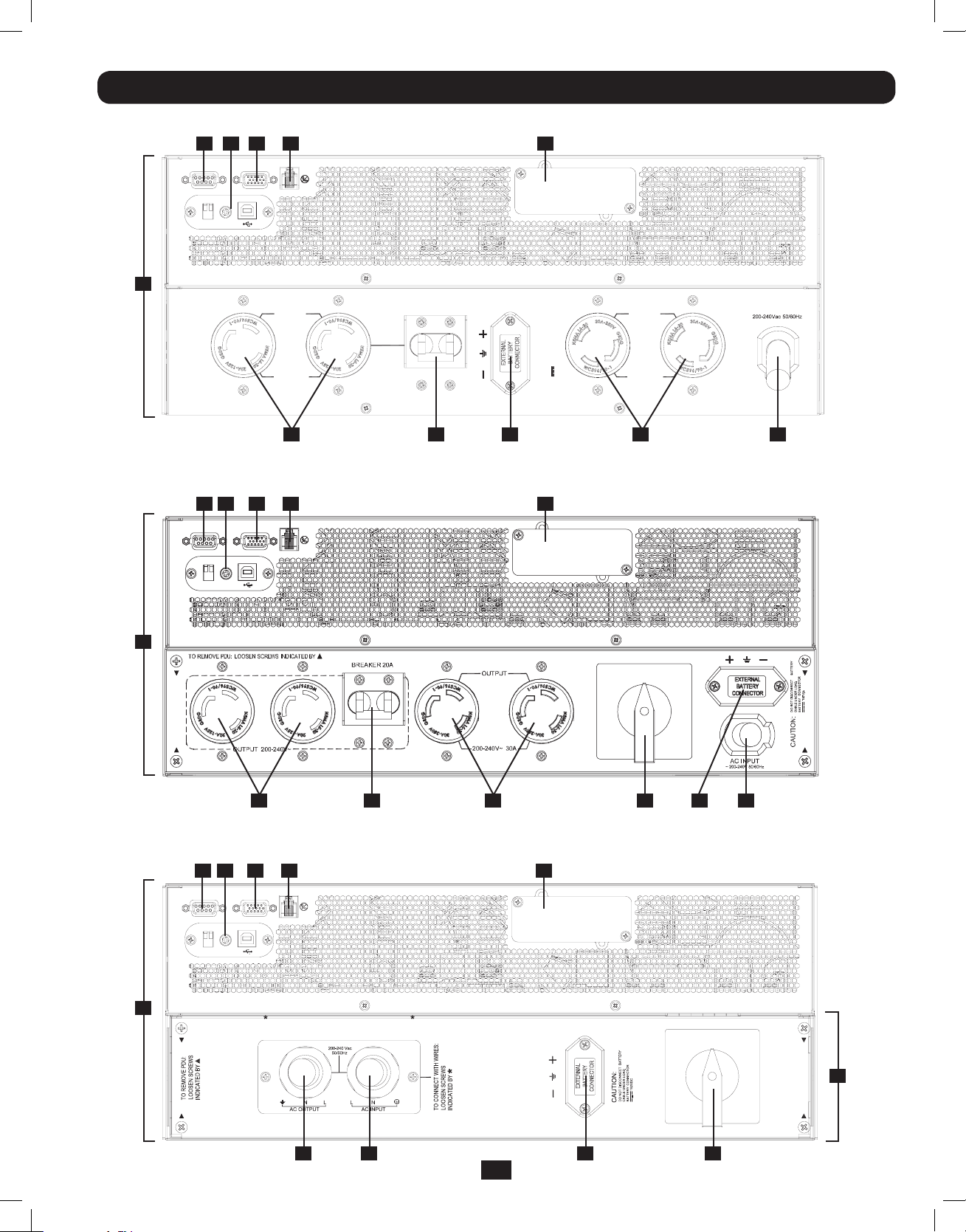
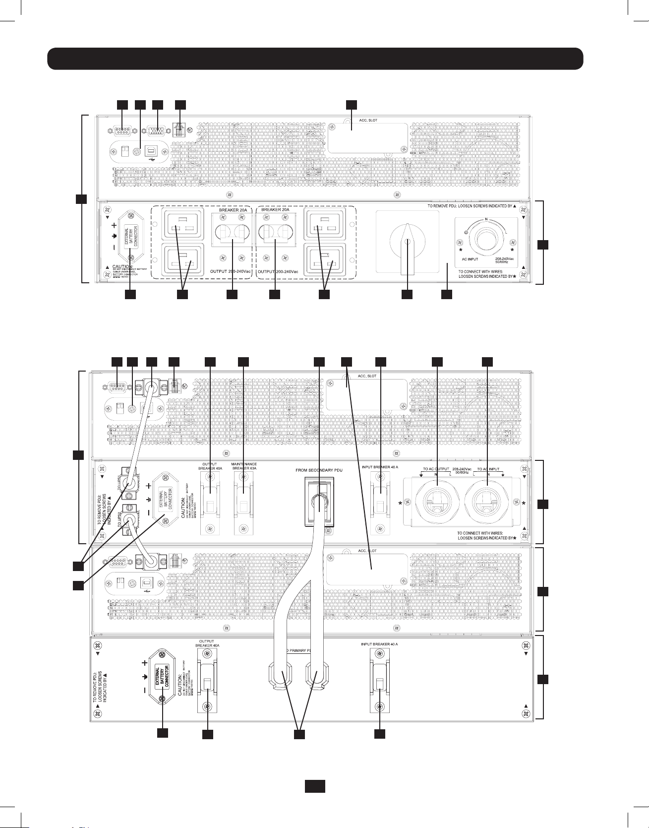
Features (Rear Panel) See “Features” section for feature descriptions
SU5000RT4UHV—5kVA UPS System
9
10
11
12
PARALLEL
EPO
1
RS-232
RS-232
USB
1
OUTPUT 2
200-240Vac
BREAKER 20A
13
BATTERY
CABLE UNDER LOAD.
DO NOT DISCONNECT
CAUTION:
CONNECTOR
192VDC
BATTERY
ACC. SLOT
OUTPUT 1
30A
200-240Vac
AC INPUT
8 7 4
SU6000RT4UHV—6kVA UPS System with NEMA PDU
9
10
11
12
RS-232
RS-232
USB
PARALLEL
EPO
1
14
8 6 5 4 37
SU6000RT4UHVHW—6kVA UPS System with Hardwire PDU
9
10
11
12
RS-232
PARALLEL
EPO
13
13
ACC. SLOT
ACC. SLOT
6 3
NORMAL
BY
PASS
RS-232
USB
1
NORMAL
PASS
BY
2
16 15 4 5
5
201207113 933070.indb 5 9/17/2012 1:19:48 PM
Page 6
Features (Rear Panel) (continued) See “Features” section for feature descriptions
SU6000RT4UHVG—6kVA UPS System with IEC PDU
9
1010111112
RS-232
RS-232
USB
PARALLEL
EPO
1
13
NORMAL
PASS
BY
2
4
21 217 7 5 15
SU12KRT4UHW—12kVA UPS System and Parallel PDU Modules
Note: See the manual included with the Parallel PDU for 12kVA installation, configuration and setup instructions.
11
9
RS-232
RS-232
USB
PARALLEL
12
EPO
1
RS-232
RS-232
4
USB
PARALLEL
EPO
20
19 18 17 16
13
15
2
22
23
4
20
18
17
6
201207113 933070.indb 6 9/17/2012 1:19:50 PM
Page 7
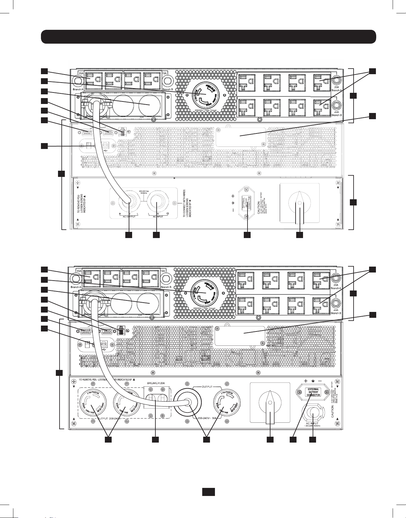
Features (Rear Panel) (continued) See “Features” sectiion for feature descriptions
SU6000RT4UTFHW—6kVA UPS with Hardwire PDU and 6kVA Isolation Step Down Transformer
(SU6000XFMR2U)
24 24
8
14
12
11
10
9
RS-232
RS-232
USB
PARALLEL
EPO
ACC. SLOT
1
NORMAL
25
13
16 15
4 5
PASS
BY
2
SU6000RT4UTF—6kVA UPS with NEMA PDU and 6KVA Isolation Transformer
24 24
8
14
12
11
10
9
RS-232
RS-232
USB
PARALLEL
EPO
ACC. SLOT
1
25
13
NORMAL
BY
PASS
14
8 6 5 4 37
7
201207113 933070.indb 7 9/17/2012 1:19:56 PM
Page 8

Features (Rear Panel) (continued)
1
UPS System: This self-contained unit houses the UPS system’s power and control components as well as its
internal batteries.
Independent, Detachable Power Distribution Unit (PDU): This self-contained unit houses the UPS system’s input and
2
output components along with a bypass switch. When the switch is set to bypass the PDU can be completely removed from
the power/battery module for routine power/battery maintenance without disrupting power to the connected loads. While this
switch is set to bypass, connected equipment will receive unfiltered AC mains power, but the equipment will not receive battery
power in the event of a blackout.
AC Input Cord: Connects directly to wall receptacle providing 200-240V AC utility power.
3
External Battery Connector: Use this to connect one or more Tripp Lite battery modules to the power module. Remove the
4
cover for access. The power module will not start without a connection to a charged battery module. Refer to the battery
module Owner’s Manual for connection instructions and safety warnings.
Maintenance Bypass Switch: This switch allows qualified service personnel to remove the detachable PDU from the power/
5
battery module for routine maintenance without disrupting power to connected loads. While this switch is set to BYPASS,
connected equipment will receive filtered AC mains power, but the equipment will not receive battery power in the event of a
blackout. See“Manual Bypass Operation” section for complete bypass procedure.
L6-30R AC Output Receptacles: Accept direct plug-in connection of NEMA L6-30 equipment plugs.
6
20A Output Breaker: One double-pole circuit breaker controls output power from the receptacles indicated on each model.
7
L6-20R AC Output Receptacles: Accept direct plug-in connection of NEMA L6-20 equipment plugs.
8
RS-232 Communication Port: This female DB9 serial port may be used to connect your UPS to a workstation or server. It
9
uses RS-232 protocol to communicate with a connected computer. It is used with Tripp Lite software and the included serial
cable to monitor and manage the UPS remotely over a network and to automatically save open files and shut down equipment
during a blackout. See“Optional Connection”section for details.
Mini-Slot: USB connector (disabled by default—DIP switches in the RS-232 position; to enable, move both DIP switches to
10
the USB position). An optional Contact-Closure card is available if needed (Tripp Lite part # RELAYIOMINI).
Parallel Connector: For UPS communication in parallel (functional only on the 6kVA model). Refer to the manual provided
11
with the Parallel PDU Kit. For more information, visit www.tripplite.com/support.
EPO (Emergency Power Off) Port: The power module features an EPO port that may be used to connect the power module
12
to a contact closure switch to enable emergency power off. See “Optional Connection” section for details.
Accessory Slot: Remove the small cover panel to install optional accessories to remotely control and monitor your UPS
13
system. Visit Tripp Lite on the Web (www.tripplite.com) to learn about available SNMP, network management and connectivity
products that may be installed in this slot.
Transformer AC Input/Output Terminal Block (6kVA UPS only): Use this terminal for interfacing an approved PDU system.
14
Utility Input Terminal Block (6kVA UPS and 12kVA IEC/PARALLEL/HARDWIRE module only): Use these terminals to
15
connect your power module to utility power. Unscrew and remove the cover over the block for access.
Equipment Output Terminal Block (6kVA UPS and 12kVA IEC/PARALLEL/HARDWIRE module only): Use these terminals
16
to connect your power module to your equipment. Unscrew and remove the cover over the block for access.
AC Input Breaker: One double-pole cicuit breaker controls input power to the power module.
17
18
Parallel Power Interconnect: For use with secondary parallel PDU only.
19
Maintenance Breaker (12kVA UPS only): Controls maintenance to the UPS.
20
AC Output Breaker: One double-pole circuit breaker provides Bypass for the parallel system to the load.
21
AC Output Receptacles (6kVA UPS/ IEC PDU Module only): Accept direct plug-in connection of IEC-320-C20
equipment plugs.
22
Secondary UPS Module
23
Secondary PDU Module
24
5-15/20R AC Output Receptacles: Accept direct plug-in connection of NEMA 5-15P or 5-20P equipment plugs.
25
Isolation Step Down Transformer: This self-contained unit provides a means to connect both low-voltage and high-voltage
devices to the UPS system.
8
201207113 933070.indb 8 9/17/2012 1:19:57 PM
Page 9
Connection
Note: The output voltage is set at 208~(default) by the manufacturer. If you need to change the output voltage of the
UPS, refer to “Output Voltage Selection” in the “Operation” section. You should select the correct output voltage before
connecting your equipment to the UPS.
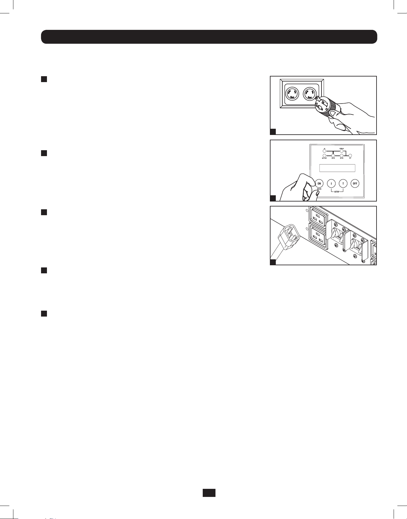
1
Plug your UPS’s input cord into an electrical outlet.
(SU5000RT4UHV, SU5000RT4UTF, SU6000RT4UHV,
SU6000RT4UTF)
Your UPS must be connected to a dedicated circuit of sufficient amperage.
Note! After you connect the UPS to a live AC power source, the UPS LCD will
display “BYPASS MODE” and will automatically charge its batteries while providing
power to the output.
If you have a PDU with manual bypass, set the PDU bypass switch to “NORMAL.”
2
Turn UPS ON.
Press the UPS’s “ON” Button until you hear a beep to begin inverter operation.
Your UPS will perform a brief self-test and show the results on the LCD Display.
See “Startup Self-Test” in the “Operation” section for the display sequence. Your
UPS will now provide filtered power to the AC output.
Note: UPS system will function properly upon initial startup; however, maximum
runtime for the unit’s battery will only be accessible after it has been charged for 24 hours.
3
Plug your equipment into your UPS.
Your UPS is designed to support electronic equipment only. You will overload your
UPS if the total VA rating for all the equipment you connect exceeds the UPS’s
output capacity. Do not connect household appliances or laser printers to the
UPS’s outlets. To find your equipment’s VA ratings, look on their nameplates. If
the equipment is listed in amps, multiply the number of amps by the input
voltage(200V~240V ) to determine VA. (Example : 1 amp x 208V = 208VA).
4
Turn UPS OFF (Optional).
Press the UPS’s “OFF” button until you hear a beep. You will be presented with a Yes/No option. Select Yes to continue to turn
off the UPS. Select No to cancel. The UPS will continue to automatically charge its batteries and provide unfiltered (BYPASSED)
AC output as long as AC input power is present. To completely deactivate the UPS, unplug the UPS’s input cord when the UPS
system is in standby mode.
1
2
3
5
UPS Cold Start (Optional).
To use your UPS as a stand-alone power source when AC input power is unavailable (i.e. during a blackout), you can “cold
start” your UPS and power connected equipment from the UPS’s battery. Your UPS’s battery must be at least partially charged
for this operation to succeed. Press and hold the “ON” button until you hear a beep to cold start your UPS. The LCD Display
will show ON BATTERY MODE. Battery power will begin discharging. Some electronic equipment may draw more amps during
startup; when cold starting, consider reducing the initial load on the UPS.
Terminal Strip Input Connections
(SU6000RT4UHVHW, SU6000RT4UHVG, SU6000RT4UTFHW)
Note: For SU12KRT4UHW Hardwiring information, see the manual included with the Parallel PDU.
Hardwiring Cautions
• Wiring must be done by a qualified electrician.
• When making wiring connections, observe the cable connection regulations appropriate to your area [e.g. National Electrical
Code (NEC) in the U.S.] at all times. Be sure to install an easily accessible disconnect switch in your installation wiring so you
may cut off the UPS’s AC input during fires and other emergencies. Ensure that cables are fitted with cable sleeves and are
secured by connector clamps. Tighten connections with a torque of not less than 24-28 inch-pounds (2.7-3.2 NM).
• Make sure that your equipment is properly grounded.
• Using cables of improper size may damage your equipment and cause fire hazards. Choose appropriate cabling and protection
circuits to make wiring connections. Ground conductors must be the same size and type as the power conductors used.
• Refer to National Electrical Code (NEC) guidelines for proper wire gauge and output protection circuit requirements.
9
201207113 933070.indb 9 9/17/2012 1:19:57 PM
Page 10
Connection (continued)
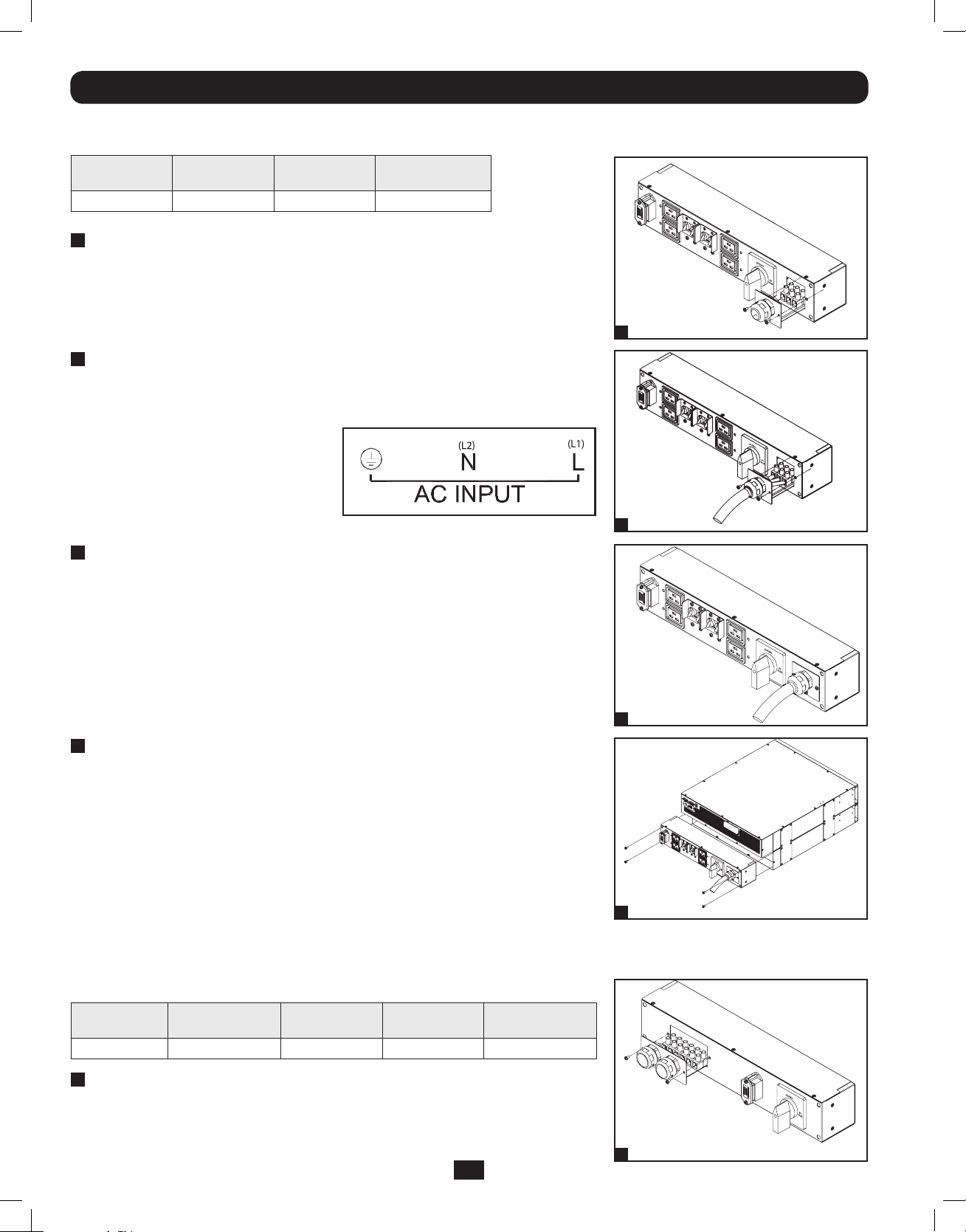
Terminal Strip Connection—IEC PDU Module (SU6000RT4UHVG)
Model Input Voltage
SUPDMB6KIEC200~240V (L-N)30A8 mm2
1
Unscrew 3 screws to remove the terminal strip cover and slide
Maximum Rated
Input Current
Typical Wire Size
out as seen in diagram 1.
2
Connect the L1, L2 and Ground wires (Hardwire-In,
Receptacle-Out) according to markings on the connectors
as seen in diagram 2.
3
Slide in and reattach the terminal strip cover with the 3
screws from Step 1.
1
2
4
Attach the PDU to the UPS system using 4 screws as seen in
diagram 4.
Terminal Strip Connection—Hardwire PDU Module
(SU6000RT4UHVHW, SU6000RT4UTHFHW)
Model Input Voltage
SUPDMB6KHW200~240V (L-N)32A30A8 mm2
1
Unscrew 3 screws to remove the terminal strip cover and slide
Maximum Rated
Input Current
out as seen in diagram 1.
Maximum Rated
Output Current
Typical Wire Size
3
4
1
10
201207113 933070.indb 10 9/17/2012 1:20:00 PM
Page 11
Connection (continued)
2
Connect the 2 sets of L1, L2 and Ground wires (1 Input, 1
Output) according to markings on the connectors as seen in
diagram 2. Be sure to connect one set of wires to the input
terminals and the other set to the output terminals.
3
Slide in and reattach the terminal strip cover with the 3
screws from Step 1.
4
Attach the PDU to the UPS system using 4 screws as seen in
diagram 4.
2
3
Hardwiring the Transformer Bundle (Input/Output)
SU6000RT4UTF
1. Plug the XFMR into the UPS.
2. Connect the transformer to the UPS. This can be a
hardwire connection, outlet connection or both,
provided the combined load does not exceed capacity.
SU12KRT4UHW
See manual included with Parallel PDU for connection,
setup and installation information.
L1 G L2 L G N N G L
208 / 240V
Input
Set Front Panel Selector Switch to Proper Voltage Before Making Connections
4
120V
Output
Branch A
120V
Output
Branch B
11
201207113 933070.indb 11 9/17/2012 1:20:01 PM
Page 12
Optional Connection
The following connections are optional. Your UPS system will function properly without these connections.
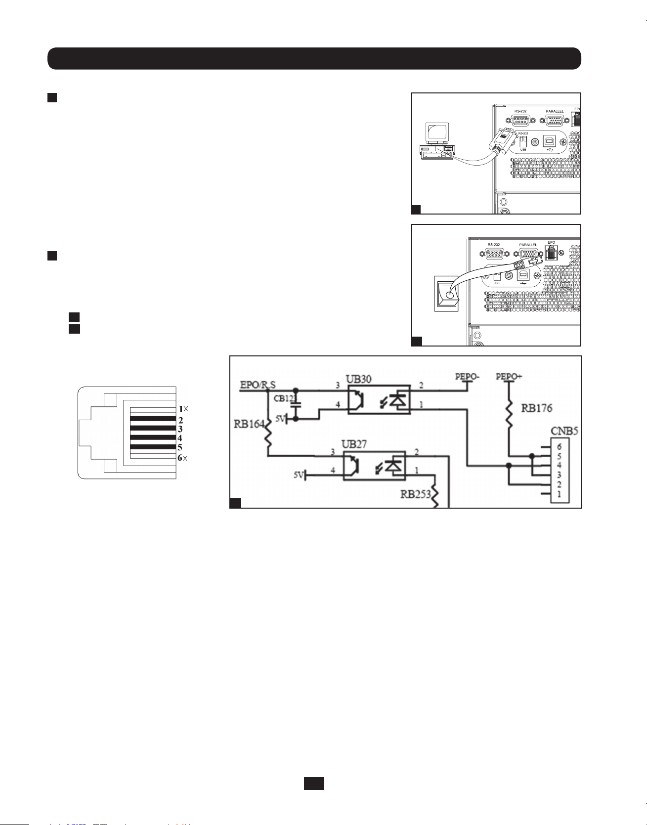
1
RS-232 Serial and USB Communication Connections
Use the included cable to connect the power module’s “RS-232” port to the
communication port on your computer. This will allow full network monitoring and
control of your UPS system. Install on your computer the Tripp Lite PowerAlert software
appropriate to your computer’s operating system. The UPS is also equipped with a
USB communication module.
An alternate contact closure module is available if necessary (Tripp Lite part #
RELAYIOMINI). By default, this module is disabled. To enable, move both DIP switches
to the USB position. Enabling this module disables the RS-232 port. The RS-232 port
is also disabled with the installation of an optional SNMP/Web card (Tripp Lite part #
SNMPWEBCARD). The SNMP/Web card can be used simultaneously with the USB
communication module.
2
EPO Port Connection
This optional feature is only for those applications that require connection to a
facility’s Emergency Power Off (EPO) circuit. When the UPS is connected to this
circuit, it enables emergency shutdown of the UPS’s inverter and inhibits transfer
to internal bypass. Using the cable provided, connect the EPO port of your UPS
(see 2a) to a user-supplied normally open switch according to the circuit diagram
(see 2b).
1
2a
EPO connector
EPO Information
Pins 4 and 5 or pins 2 and 3 can be
shorted to activate the EPO.
Note:
1. If using a cable other than what is supplied, the cable should not exceed 350 feet or have a resistance of greater than 10 ohms.
2. If a non-latching EPO switch is used, the EPO must be held for a minimum of 1 second. This does not apply to a latching EPO switch.
3. For setup of a normally closed-switch EPO connection, please contact Tripp Lite Technical Support.
CAUTION: The EPO port is not a phone line surge suppressor; do not connect a phone line to this port.
2b
12
201207113 933070.indb 12 9/17/2012 1:20:03 PM
Page 13
Optional Connection (continued)
UPS Unit State when asserting EPO with AC line present:
LEDsOutputFansSerialSNMPUSB LCD Screen
OFFOFFOFFOFFOFFOFF“Emergency Stop”
To restart the UPS unit after asserting EPO with AC line present:
1. Verify that the EPO assertion has been removed or cleared.
2. Remove AC line power to the UPS unit.
3. Reapply AC line power. Now the UPS will start back up in Bypass mode and the LCD will display “BYPASS MODE”.
UPS Unit State when asserting EPO without AC line power:
LEDsOutputFansSerialSNMPUSB LCD Screen
OFFOFFOFFOFFOFFOFF“Emergency Stop”
To restart the UPS unit after asserting EPO without AC line power:
1. Verify that the EPO assertion has been removed or cleared.
2. Reapply AC line power to the UPS unit. Now the UPS will start back up in Bypass mode and the LCD will display
“BYPASS MODE”.
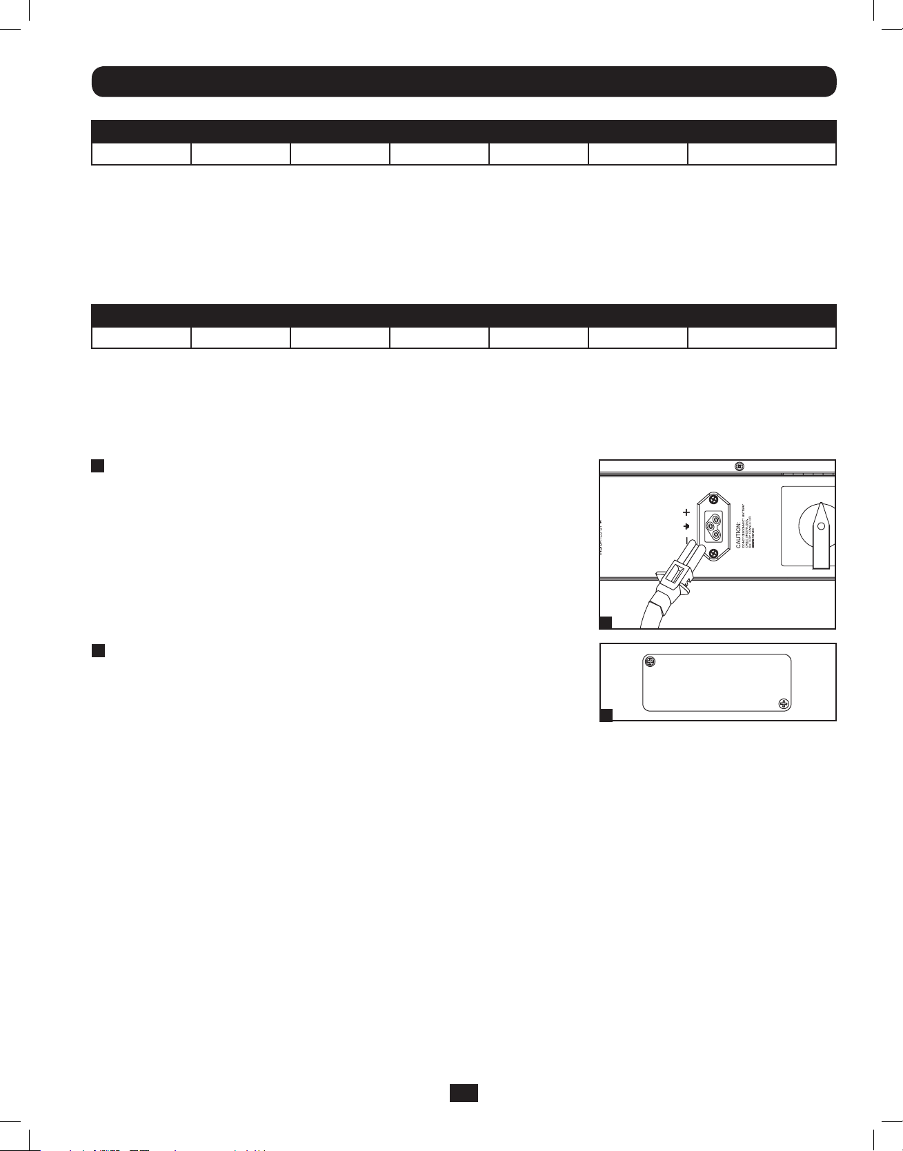
3
External Battery Connection
Your UPS comes with a robust internal battery system; external batteries are needed
only to extend runtime. Adding external batteries will increase recharge time as well as
runtime. The illustration shows the location of your UPS’s External Battery Connector,
where you will insert the battery pack cable. Complete installation instructions for your
battery pack appear in the battery pack Owner’s Manual. Make sure that cables are
fully inserted into their connectors. Small sparks may result during battery connection;
this is normal. Do not connect or disconnect battery packs when the UPS is running
on battery power.
3
NORMAL
4
Accessory Slot
Remove the slot’s cover to install an optional internal SNMP/Web accessory card
(Model: SNMPWEBCARD) to enable remote UPS monitoring and control via SNMP,
Web or telnet. (Tripp Lite’s RELAYIOCARD is also available.) Visit www.tripplite.com/
support for more information, including a list of available SNMP, network management
and connectivity products.
4
13
201207113 933070.indb 13 9/17/2012 1:20:04 PM
Page 14
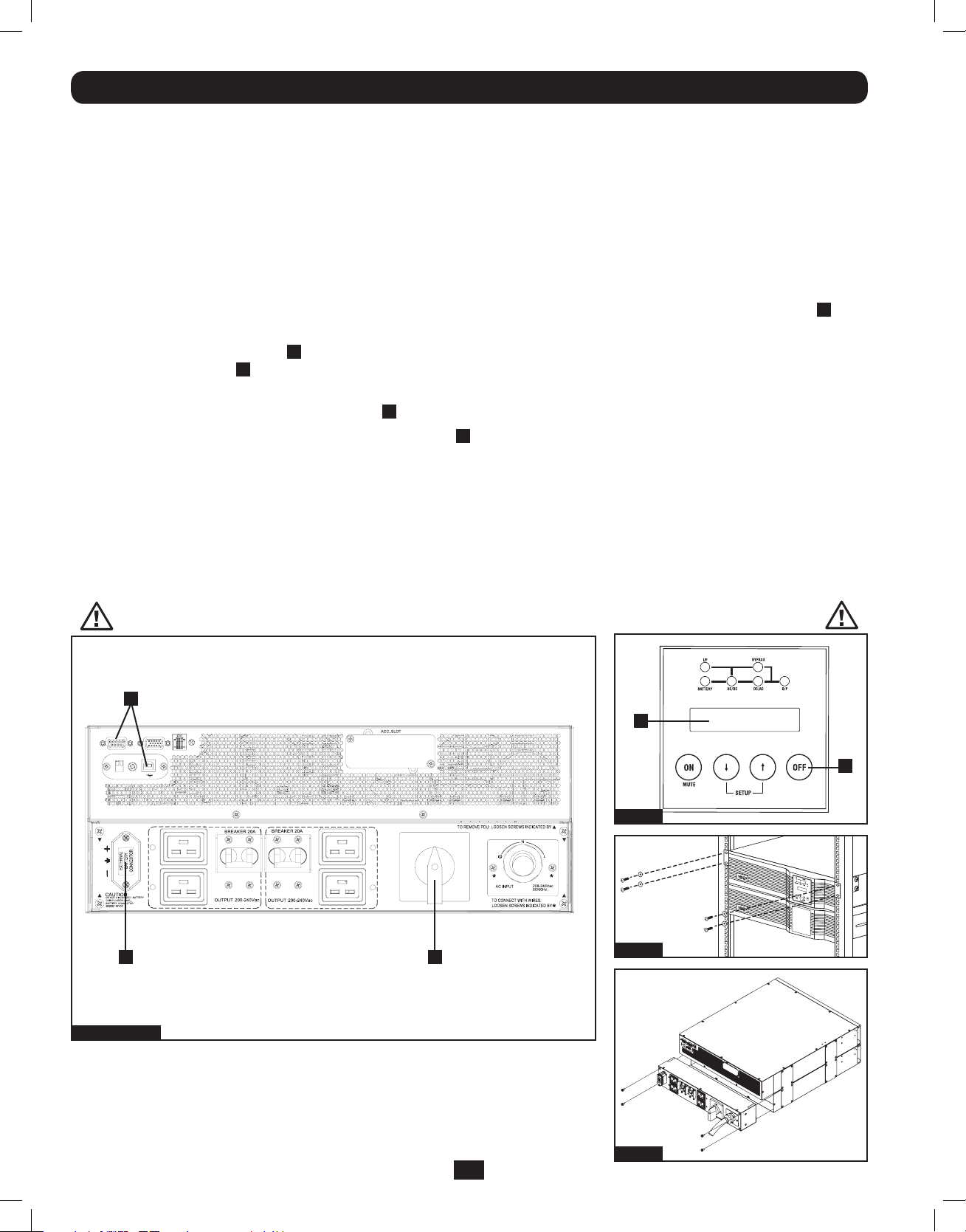
Hot-Swap Power Module Replacement*
WARNING! For qualified service personnel only. Failure to follow the bypass procedure completely will not adequately
power down the UPS, resulting in the continued risk of death or injury from pontential contact with high voltage. The
UPS and detachable PDU are extremely heavy. This procedure requires several people to perform.
The UPS system includes an independent, detachable PDU with a Bypass Switch. This switch allows qualified service personnel to
remove the detachable PDU from the UPS for routine maintenance without disrupting power to connected loads. While this switch
is set to “BYPASS”, connected equipment will receive unfiltered AC mains power. But the equipment will not receive battery power
in the event of a blackout.
* See manual included with SU12KRT4UHW Parallel PDU for Bypass.
UPS Removal (6kVA Single UPS Power Module Configurations Only)
STEP 1. Disable PowerAlert and disconnect the SNMP or serial USB communication cables from the communication ports
A
on
the UPS.
STEP 2. Press UPS’s “OFF” button B , if the UPS is powered, until you hear a beep and see a “BYPASS MODE” message shown
in its LCD Display C on the front of the power module. You will be prompted to enter “BYPASS MODE”. Press UPS “OFF”
button again to activate “BYPASS MODE”.
STEP 3. Turn the detachable PDU’s Bypass Switch D to “BYPASS” on the rear of the UPS PDU.
STEP 4. If an external battery module is connected to the UPS E, disconnect it from the UPS.
The UPS is now safely powered down and it can be detached from the PDU to perform maintenance/replacement.
STEP 5. Remove the four screws that secure the front mounting ears of your UPS to the rack. With the PDU still attached, move
the UPS system and PDU forward in the rack slightly (approximately 4 inches), being sure that both components remain
adequately supported by the UPS’s rackmount support rails.
STEP 6. At the rear of the UPS, remove the four screws that hold the detachable PDU to the UPS that is being serviced. With an
assistant holding the front of the UPS in place, carefully detach the PDU from the rear of the UPS and rest it on the UPS
support rails. Remove the UPS power module from the front of the rack.
WARNING! High voltage! Risk of electrical shock!
A
RS-232
EPO
PARALLEL
RS-232
USB
C
B
Step 2
NORMAL
BY
PASS
E D
Steps 1, 3 & 4
14
201207113 933070.indb 14 9/17/2012 1:20:05 PM
Step 5
Step 6
Page 15
Operation
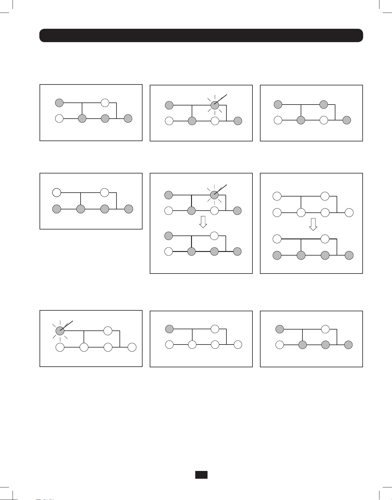
LED Display Information
ONLINE Mode: AC input voltage in
normal range: 156-280V.
IP BYPASS
AC/DCBATTERY DC/AC O/P
Battery Mode: When in Battery Mode,
you will see the following LED display:
IP BYPASS
AC/DC DC/ACBATTERY O/P
Bypass Mode: AC input voltage in a
range of: -20 to +15% of the rating
voltage; Bypass Mode is enabled.
IP BYPASS
BATTERY DC/AC O/P
AC/DC
Flashing
AC Power Start Up: With an AC power
start up, you will see the following LED
sequence:
IP BYPASS
AC/DC DC/ACBATTERY O/P
IP BYPASS
Flashing
Economy Mode: AC input voltage in a
range between -10 and +10% of rating
voltage; Economy Mode is enabled.
IP BYPASS
BATTERY DC/AC
AC/DC O/P
Cold Start: With a cold start, an On
Battery Alarm will sound, and you will see
the following LED sequence:
IP BYPASS
BATTERY
IP BYPASS
AC/DC DC/AC O/P
EPO Shutdown (Frequency Conversion
Mode): With an EPO shutdown with no
output present, you will see the following
LED sequence:
Flashing
IP
BATTERY DC/AC
AC/DC O/P
BYPASS
AC/DC
DC/ACBATTERY O/P
EPO Shutdown (AC Mode): With an
EPO shutdown having AC power present,
you will see the following LED sequence:
BYPASSIP
BATTERY DC/ACAC/DC O/P
BATTERY AC/DC
DC/AC O/P
Battery Independent Mode: In Battery
Independent Mode, the same LED
sequence as ONLINE Mode will display,
but a “Bad Battery Alarm” will sound.
IP BYPASS
AC/DCBATTERY DC/AC O/P
15
201207113 933070.indb 15 9/17/2012 1:20:07 PM
Page 16
Operation (continued)
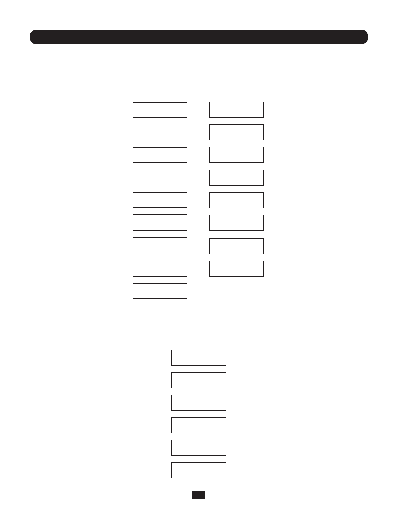
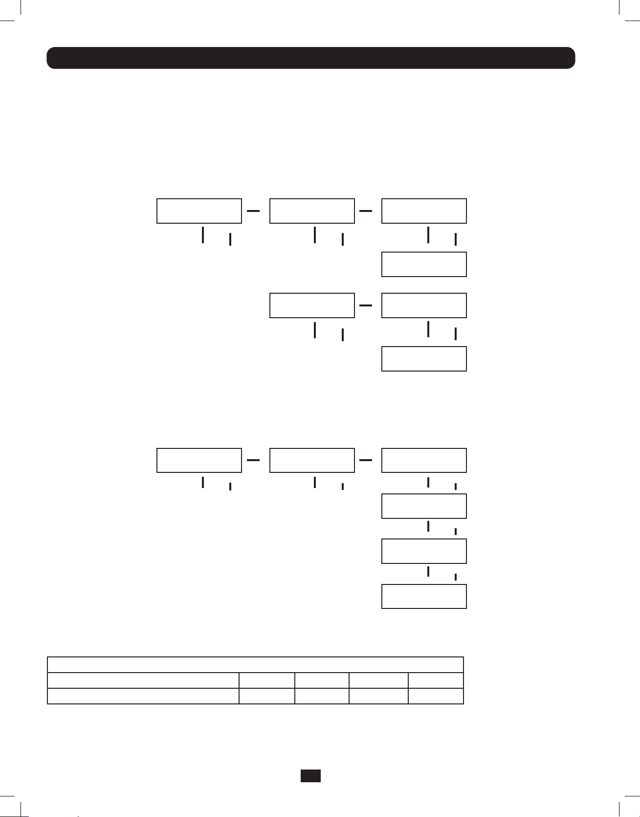
Startup Self-Test
When you turn the UPS ON, it will enter Diagnostic Mode and perform a brief self-test lasting about 15 seconds. The results of the
self-test are shown on the LCD screen in the sequence below.
*Note: If the UPS is cold started,
its BATTERY LED will be lit.
STARTED WITH
AC INPUT
DIAGNOSTIC MODE
FREQ OUT = 50Hz
DIAGNOSTIC MODE
INPUT 000V / 00Hz
DIAGNOSTIC MODE
RECTIFIER OK
DIAGNOSTIC MODE
CHARGER OK
DIAGNOSTIC MODE
BATTERY OK
DIAGNOSTIC MODE
DC BUS OK
DIAGNOSTIC MODE
INVERTER TEST
DIAGNOSTIC MODE
INVERTER OK
LOAD LEVEL
00.00KW / 000%
COLD
START*
DIAGNOSTIC MODE
FREQ OUT = 50Hz
DIAGNOSTIC MODE
INPUT 000V / 00Hz
DIAGNOSTIC MODE
RECTIFIER OK
DIAGNOSTIC MODE
BATTERY OK
DIAGNOSTIC MODE
DC BUS OK
DIAGNOSTIC MODE
INVERTER TEST
DIAGNOSTIC MODE
INVERTER OK
LOAD LEVEL
00.00V / 000%
Failed Self-Test
If a problem is detected during the self-test, the LCD will display an error message. If your UPS displays any of the following
messages in its LCD, visit www.tripplite.com/support for service.
BAD BATTERY!
CALL FOR SERVICE
CHARGE BATT FAIL!
CALL FOR SERVICE
AC/DC FAILURE!
CALL FOR SERVICE
INVERTER FAILURE!
CALL FOR SERVICE
OUTPUT FAILURE!
CALL FOR SERVICE
FAN FAILURE!
CALL FOR SERVICE
16
201207113 933070.indb 16 9/17/2012 1:20:07 PM
Page 17
Operation (continued)
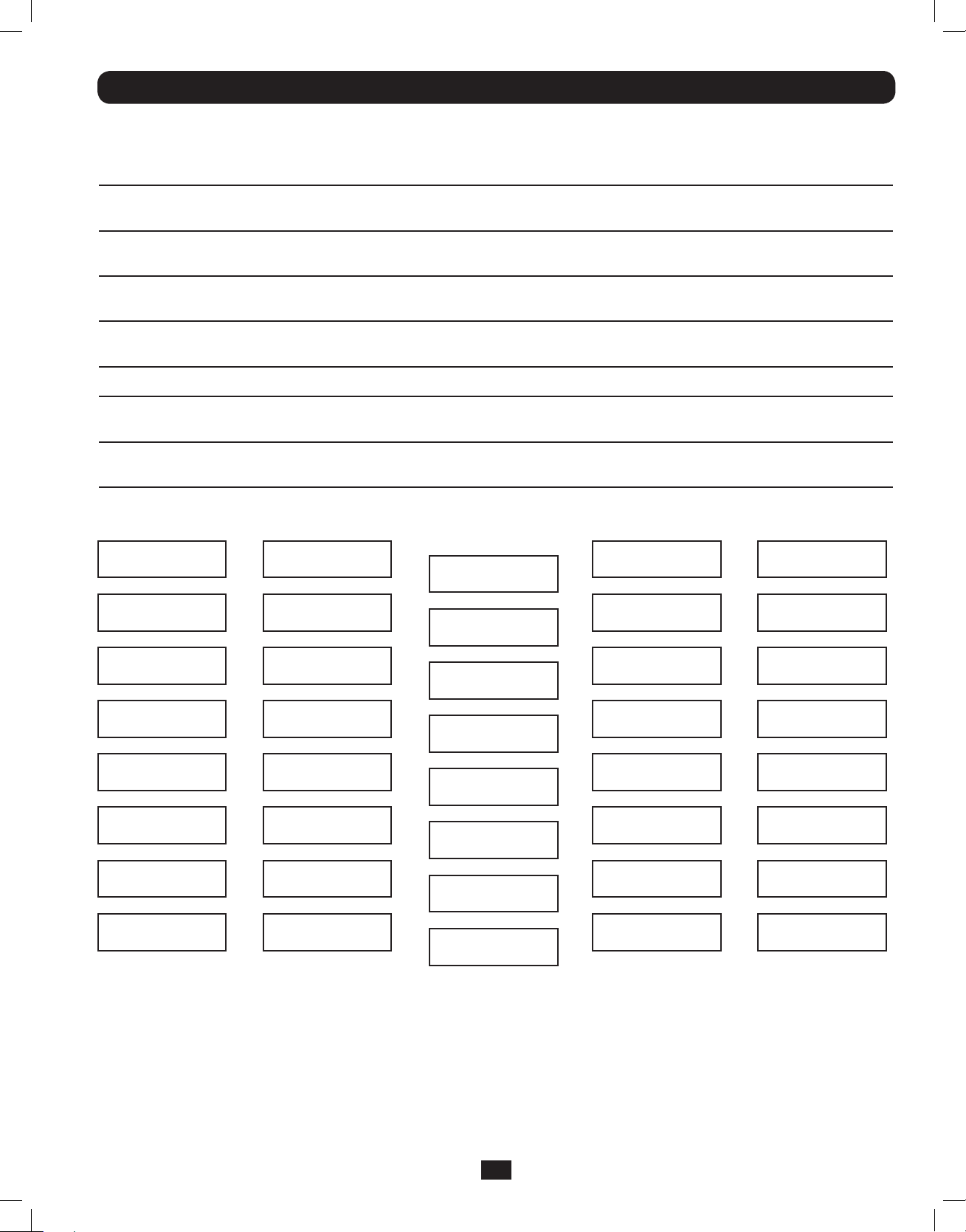
Normal Operation
During normal operation, the first line of your LCD Display shows which operating mode your UPS is in: Online Mode, Economy Mode,
Frequency Conversion Mode, Battery Mode, Bypass Mode or Parallel Mode (12kVA model only).
Online Mode: The UPS provides AC power while utility power is available and switches to On Battery Mode instantly (zero transfer time) if
AC power is interrupted.
Economy Mode: The UPS provides AC power at high efficiency while utility power is within +/- 10% rated AC input voltage and switches to
On Battery Mode (8ms transfer time) if AC power is interrupted.
Frequency Conversion Mode: Used to convert your UPS’s input frequency to a different output frequency (i.e. Input 60 Hz to Output 50
Hz. Note: Output will be turned off in Frequency Conversion Mode if the unit is put into Bypass).
Battery Mode: The UPS provides AC power from battery backup so long as battery power lasts. It switches back to Online or Economy
Mode if utility power is available and shuts down if it runs out of battery power.
Bypass Mode: The UPS provides AC power while utility power is available. The UPS shuts down if AC power is interrupted.
Parallel Mode (SU12KRT4UHW model only): The UPS can provide redundancy up to 6kVA or power up to 12kVA. Refer to the manual
provided with the Parallel PDU Kit for more information.
The second line of the LCD Display shows basic power conditions. In each operating mode you can push the SCROLL buttons to browse
through these basic power conditions in the sequences shown below:
Display Information
Online Mode:
ONLINE MODE
00.00KW / 000%
STANDALONE
00.00KVA / 000%
INPUT VOLTAGE
000V / 00.0Hz
BYPASS VOLTAGE
000V / 00.0Hz
OUTPUT VOLTAGE
000V / 00.0Hz
BATTERY CAPACITY
000V / 000%
REMAINING TIME
0000 MINUTES
ON-LINE 5/6KVA
V00 CV01
Display Information
Economy Mode:
ECONOMY MODE
00.00KW / 000%
STANDALONE
00.00KVA / 000%
INPUT VOLTAGE
000V / 00.0Hz
BYPASS VOLTAGE
000V / 00.0Hz
OUTPUT VOLTAGE
000V / 00.0Hz
BATTERY CAPACITY
000V / 000%
REMAINING TIME
0000 MINUTES
ON-LINE 5/6KVA
V00 CV01
Display Information
Frequency
Conversion Mode:
FREQ CONV MODE
00.00KW / 000%
STANDALONE
00.00KVA / 000%
INPUT VOLTAGE
000V / 00.0Hz
BYPASS VOLTAGE
000V / 00.0Hz
OUTPUT VOLTAGE
000V / 00.0Hz
BATTERY CAPACITY
000V / 000%
REMAINING TIME
0000 MINUTES
ON-LINE 5/6KVA
V00 CV01
Display Information
Battery Mode:
BATTERY MODE
00.00KW / 000%
STANDALONE
00.00KVA / 000%
INPUT VOLTAGE
000V / 00.0Hz
BYPASS VOLTAGE
000V / 00.0Hz
OUTPUT VOLTAGE
000V / 00.0Hz
BATTERY CAPACITY
000V / 000%
REMAINING TIME
0000 MINUTES
ON-LINE 5/6KVA
V00 CV01
Display Information
Bypass Mode:
BYPASS MODE
00.00KW / 000%
STANDALONE
00.00KVA / 000%
INPUT VOLTAGE
000V / 00.0Hz
BYPASS VOLTAGE
000V / 00.0Hz
OUTPUT VOLTAGE
000V / 00.0Hz
BATTERY CAPACITY
000V / 000%
REMAINING TIME
0000 MINUTES
ON-LINE 5/6KVA
V00 CV01
17
201207113 933070.indb 17 9/17/2012 1:20:08 PM
Page 18
Operation (continued)
Normal Operation
Display Information Parallel Mode (12kVA model only):
PARALLEL MODE
00.00KW / 000%
PARALLEL: MASTER
00.00KVA / 000%
INPUT VOLTAGE
000V / 00.0Hz
BYPASS VOLTAGE
000V / 00.0Hz
OUTPUT VOLTAGE
000V / 00.0Hz
BATTERY CAPACITY
000V / 000%
REMAINING TIME
0000 MINUTES
ON-LINE 6KVA
V00 CV01
NOTE: When two units are connected in parallel, the
“Master UPS” will display “PARALLEL: MASTER” in
this second screen. The display on the “Secondary
UPS” will read “PARALLEL: SLAVE”. If the two units
are not paralleled successfully, both units will read
“STANDALONE” in this second screen.
UPS Setup Menu
Press the UPh and DOWNi buttons simultaneously for 3 seconds until the SETUP MENU screen appears as seen below:
UPS SETUP
EXIT ENTER
Press the UPh button to enter Set Up Mode.
To enter Set Up Mode, you will be required to enter a password.
PASSWORD : 0000
ENT DOWN UP XX
Numbers increase or decrease by 1 when pressing the UPh and DOWNi buttons (0-9). Scroll to select the first number, then press
the ON button. This saves the first number and moves on to the next in the sequence. The password range is 0000-9999 and
should be changed by the administrator. The DEFAULT password is 1234.
18
201207113 933070.indb 18 9/17/2012 1:20:08 PM
Page 19
Operation (continued)
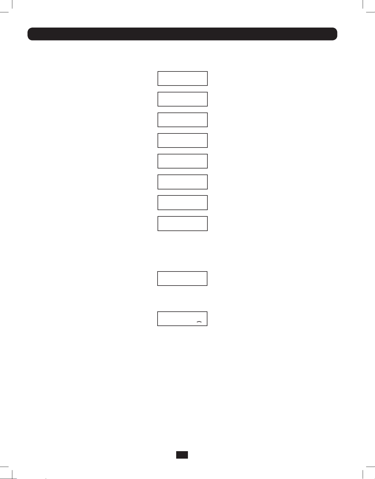
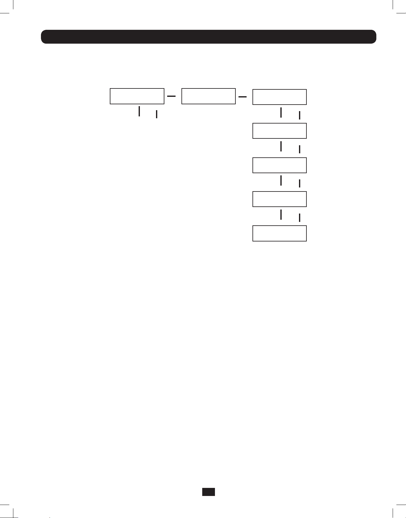
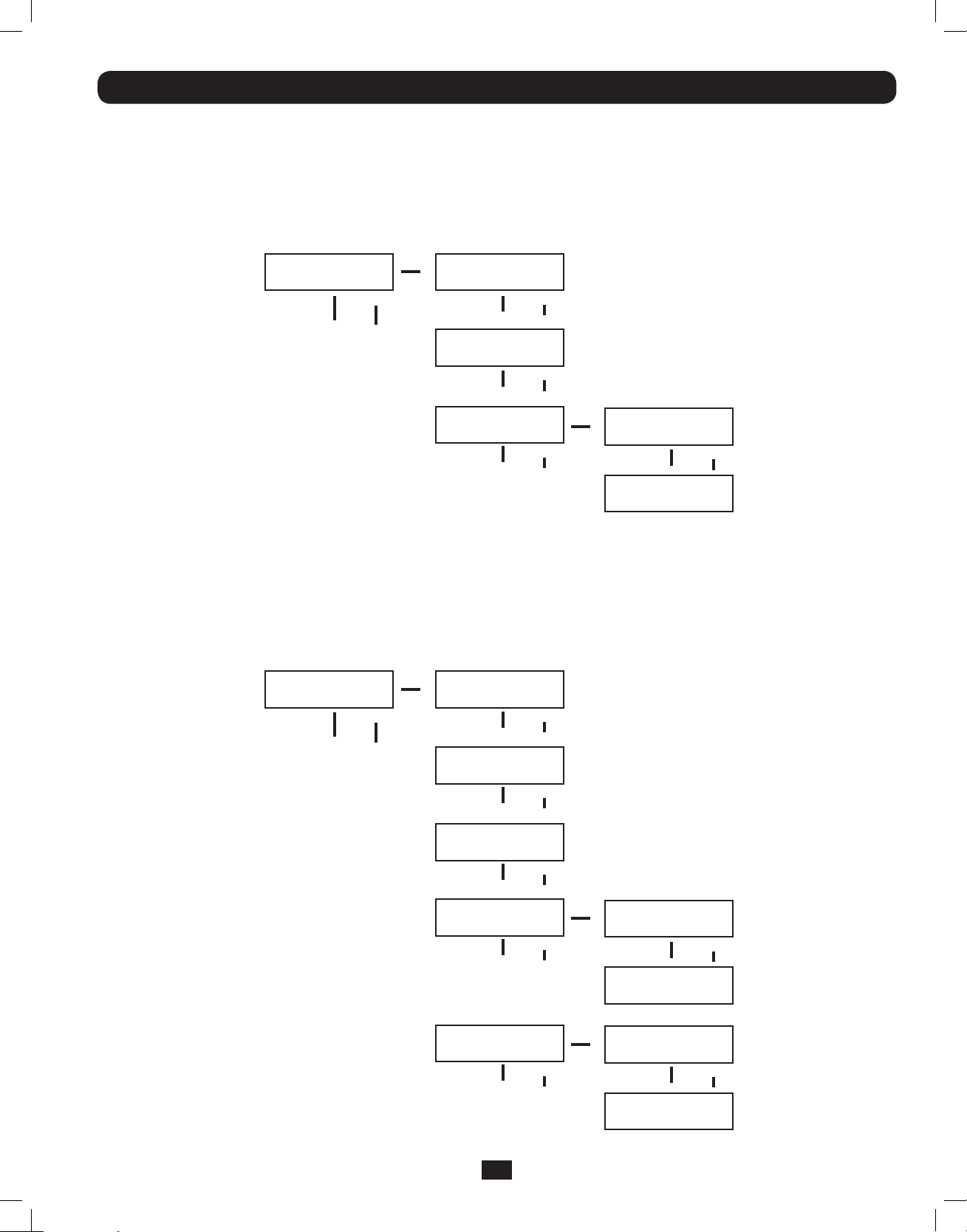
Changing the Password
To change the password, scroll DOWNi from the SETUP MENU screen to the BASIS SETTING screen. From here, press ON for the
CHANGE PASSWORD screen. From this screen press ON and follow the previously described actions to set your password. When
set, press ON to move to the SAVING screen. Scroll DOWNi to the SAVING:YES screen and press ON to save. Scrolling back UPh
will return you to the SETUP MENU.
SETUP MENU
ENT DOWN UP
Down
BASIS SETTING
ENT DOWN UP
On On
CHANGE PASSWORD?
ENT DOWN UP
FOLLOW
SEQUENCE
PAGE 17
On
SAVING: NO
ENT DOWN UP
Down
SAVING: YES
ENT DOWN UP
On
Scroll uph back to
SETUP MENU
Selecting Screen Language
To select a screen language, scroll DOWNi to the BASIS SETTING screen. Press ON to get to the CHANGE PASSWORD screen and
DOWNi to get to the LANGUAGE screen. From here, press ON. You can then scroll DOWNi or UPh through languages until you
find your desired language. Press ON to save your selection.
SETUP MENU
ENT DOWN UP
Down
BASIS SETTING
ENT DOWN UP
On
CHANGE PASSWORD?
ENT DOWN UP
LANGUAGE
ENT DOWN UP
Down
On
ENT DOWN UP
ENGLISH
SCROLL
DOWN or UP
THROUGH
LANGUAGES
ENGLISH
ENT DOWN UP
On
19
201207113 933070.indb 19 9/17/2012 1:20:08 PM
Page 20
Operation (continued)
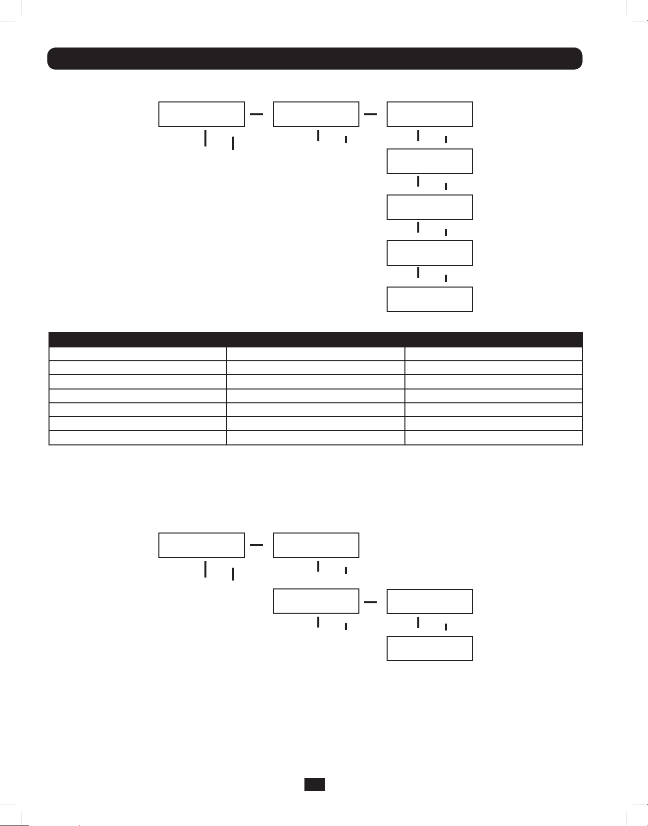
Start Settings
The UPS can start up through the battery without AC power. The DEFAULT is ENABLE. When the UPS switches to battery it can
AUTO RESTART to work in an On-Line Mode when AC power is restored. DEFAULT is ENABLE.
From the SETUP MENU screen, scroll DOWNi to the START SETTING screen. From here, press the ON button for the BATTERY
START screen. From this screen, pressing ON moves you to a ENABLE screen. Pressing ON will ENABLE, while scrolling DOWNi
takes you to a DISABLE screen. From here, press ON to DISABLE this function.
From the BATTERY START screen, pressing DOWNi will take you to an AUTO RESTART screen. Pressing ON takes you to an
ENABLE screen; press ON to ENABLE. Pressing DOWNi takes you to a DISABLE screen. Press ON to DISABLE this function.
START SETTING
ENT DOWN UP
To ENTER
BATTERY START
ENT DOWN UP
AUTO RESTART
ENT DOWN UP
*ENABLE*
ENT DOWN UP
DISABLE
ENT DOWN UP
*ENABLE*
ENT DOWN UP
DISABLE
ENT DOWN UP
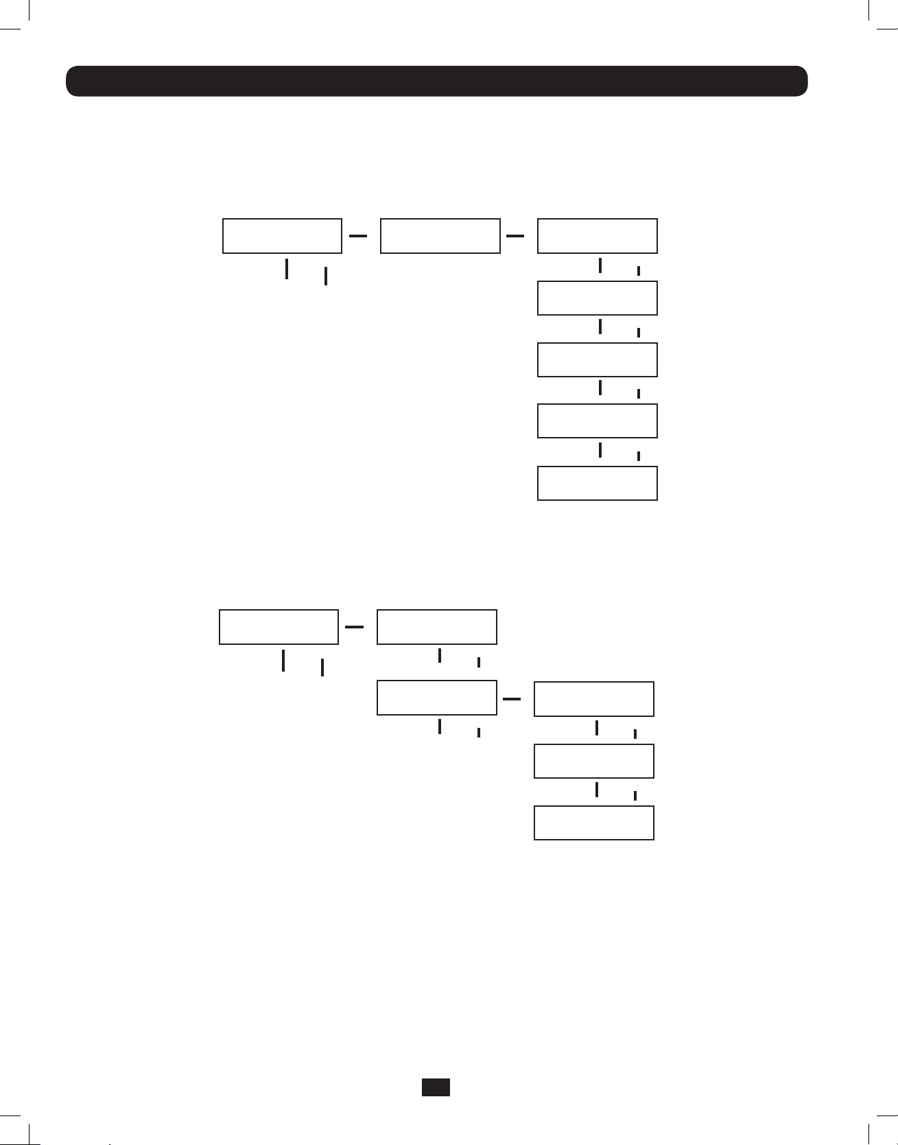
Charger Settings
From the SETUP MENU screen, scroll DOWNi until you reach the CHARGER SETTING screen. From here, press ON to get to the
CHARGER CURRENT screen. Press ON again. From here, you can scroll DOWNi or UPh to select current values between 0.7 and
4.0 A. Press ON to save your desired value. The DEFAULT selection is 0.7A.
CHARGER SETTING
ENT DOWN UP
To ENTER
CHARGER CURRENT
ENT DOWN UP
CURRENT = 0.7A
ENT DOWN UP
CURRENT = 1.5A
ENT DOWN UP
CURRENT = 3.0A
ENT DOWN UP
CURRENT = 4.0A*
ENT DOWN UP
Use the following table as a guide for charger settings based on the number of battery packs you are using.
UPS Charge Current Setting for 5/6kVA Models
Internal Battery Pack + External Battery Packs1 2 3-67 or more
Charge Current Setting0.7A1.5A3.0A4.0A
UPS Charge Current Settings for the 12kVA Model
Use the same charger current settings as the 5/6kVA models for each power module of the SU12KRT4UHW. The number of
connected external battery packs must be equal on each power module of the SU12KRT4UHW.
20
201207113 933070.indb 20 9/17/2012 1:20:08 PM
Page 21
Operation (continued)
Battery Settings
Discharge Test: Used to set the time period for discharge tests. From the SETUP MENU screen, scroll DOWNi until you reach the
BATTERY SETTING screen. Press ON for the DISCHARGE TEST screen. Here, press ON. Now you can scroll DOWNi or UPh between
NO TEST, 30, 60, 90 days and QUICK TEST. When you reach your desired time length, press ON to save. The DEFAULT is NO TEST.
BATTERY SETTING
ENT DOWN UP
To ENTER
DISCHARGE TEST
ENT DOWN UP
*NO TEST*
ENT DOWN UP
30 DAYS
ENT DOWN UP
60 DAYS
ENT DOWN UP
90 DAYS
ENT DOWN UP
QUICK TEST
ENT DOWN UP
21
201207113 933070.indb 21 9/17/2012 1:20:08 PM
Page 22
Operation (continued)
Output Settings
Note: Any Output Setting changes require a UPS power cycle.
Output Voltage: Used to set the UPS’ output voltage rating. From the SETUP MENU screen, scroll DOWNi until you reach the
OUTPUT SETTING screen. Press ON to reach an OUTPUT VOLTAGE screen and ON again. You can now scroll DOWNi or UPh
between 5 voltage values: 200/208/220/230/240V. Press ON to save your desired voltage. DEFAULT is set to 208V.
OUTPUT SETTING
ENT DOWN UP
To ENTER
OUTPUT VOLTAGE
ENT DOWN UP
*230V*
ENT DOWN UP
220V
ENT DOWN UP
208V
ENT DOWN UP
200V
ENT DOWN UP
240V
ENT DOWN UP
Frequency Converter: Used to set the Frequency Converter Mode. From the SETUP MENU screen, scroll DOWNi until you reach
the OUTPUT SETTING screen. Press ENTER for the OUTPUT VOLTAGE screen and DOWNi to access the FREQ CONVERTER screen.
Here, press ON. Now you can scroll DOWNi or UPh between DISABLE, 50 and 60 Hz. Press ON to save your selection. When on
DISABLE, the UPS will automatically detect input frequency and select 50 or 60 Hz accordingly. The DEFAULT selection is DISABLE.
OUTPUT SETTING
ENT DOWN UP
To ENTER
OUTPUT VOLTAGE
ENT DOWN UP
FREQ. CONVERTER
ENT DOWN UP
*DISABLE*
ENT DOWN UP
50Hz
ENT DOWN UP
60Hz
ENT DOWN UP
22
201207113 933070.indb 22 9/17/2012 1:20:08 PM
Page 23
Operation (continued)
Output Settings
ECO Mode: Used to set the UPS’s ability to work in the energy saving Economy Mode. When input voltage is in a + or - range of
10% of the overall voltage rating, the UPS will transfer into an Economy Mode to improve the efficiency of the UPS. From the
SETUP MENU screen, scroll DOWNi until you reach the OUTPUT SETTING screen. From here, press ON for the OUTPUT VOLTAGE
screen, and DOWNi through the FREQ CONVERTER screen until you reach the ECO MODE screen. From here, press ON and now
you can scroll DOWNi or UPh between DISABLE and ENABLE. Press ON to save your selection. The DEFAULT setting is DISABLE.
OUTPUT SETTING
ENT DOWN UP
To ENTER
OUTPUT VOLTAGE
ENT DOWN UP
FREQ. CONVERTER
ENT DOWN UP
ECO MODE
ENT DOWN UP
*DISABLE*
ENT DOWN UP
ENABLE
ENT DOWN UP
Industrial: Used to set the UPS’s voltage protection. If enabled, and receiving AC power with input voltage and frequency within a
normal range the UPS will work in an On-Line mode. If the UPS detects an output voltage fluctuation more than 5 ms, the UPS will
transfer to Bypass Mode, returning to On-Line Mode when the output is back to normal. From the STARTUP MENU screen, scroll
DOWNi until you reach the OUTPUT SETTING screen. From here, press ON to reach the OUTPUT VOLTAGE screen, and DOWNi
until you reach the INDUSTRIAL screen. From here, press ON and you can now scroll DOWNi or UPh for ENABLE or DISABLE.
Press ON to save your selection. The DEFAULT is DISABLE. Scrolling DOWN from the INDUSTRIAL screen will take you to a
REDUNDANCY screen. From here, press ON and you can now scroll DOWN or UP for ENABLE or DISABLE. The DEFAULT setting is
DISABLE.
OUTPUT SETTING
ENT DOWN UP
To ENTER
OUTPUT VOLTAGE
ENT DOWN UP
FREQ. CONVERTER
ENT DOWN UP
ECO MODE
ENT DOWN UP
INDUSTRIAL
ENT DOWN UP
REDUNDANCY
ENT DOWN UP
23
201207113 933070.indb 23 9/17/2012 1:20:08 PM
*ENABLE*
ENT DOWN UP
DISABLE
ENT DOWN UP
*ENABLE*
ENT DOWN UP
DISABLE
ENT DOWN UP
Page 24
Operation (continued)
UPS Alarm Log
UPS ALARM LOG
ENT DOWN UP
To ENTER
READ FROM MEMORY
ENT DOWN UP
1 65535 HH:MM:SS
NO HISTORY
2 65535 HH:MM:SS
NO HISTORY
3 65535 HH:MM:SS
NO HISTORY
4 65535 HH:MM:SS
NO HISTORY
5 65535 HH:MM:SS
NO HISTORY
Read From Memory: Records the last 5 fault events from the EEPROM. See the Fail Event List below:
Fail Event List
DC BUS FAILCHARGER BATTERY FAILDC BUS OVP FAIL
SHORT CIRCUITBYPASS SCR SHORT FAILINPUT HVP RELAY SHORT FAIL
INVERTER FAILINPUT SCR SHORT FAILINPUT HVP RELAY OPEN FAIL
OVER TEMPERATUREENERGY SAVINGNTC OPEN FAIL
OUTPUT SCR FAILOUTPUT HAS VOLTAGELOW TEMP FAIL
OVERLOADINPUT FUSE FAIL
FAN FAILOUTPUT FUSE FAIL
From the SETUP MENU screen, scroll DOWNi until you reach the UPS ALARM LOG screen. Press ON to enter the READ FROM
MEMORY screen and ON again. Here, you can scroll DOWNi or UPh to read the last 5 fault events. Press ON to exit this menu.
Erase All: Used to clear the Fault Event Log. From the STARTUP MENU, scroll DOWNi until you reach the UPS ALARM LOG screen.
From here, press ON to reach the READ FROM MEMORY screen and press DOWNi for the ERASE ALL screen. From here you can
scroll DOWNi or UPh between Yes and No. Press ON to save your selection. You will now be presented with a SURE? screen.
Press ON to save or scroll for more options.
UPS ALARM LOG
ENT DOWN UP
To ENTER
READ FROM MEMORY
ENT DOWN UP
ERASE ALL
ENT DOWN UP
NO
NO HISTORY
YES
NO HISTORY
24
201207113 933070.indb 24 9/17/2012 1:20:08 PM
Page 25
Operation (continued)
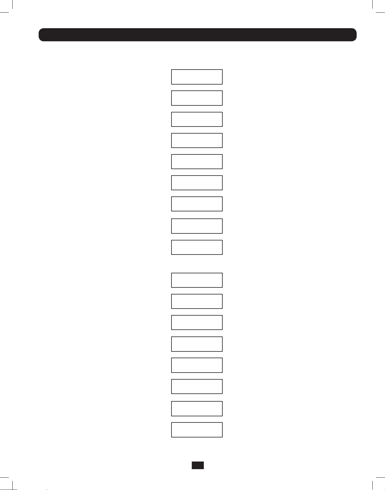
Self Diagnosis Information
When starting with AC power, you will see the following sequence display:
DIAGNOSTIC MODE
FREQ OUT = 50Hz
DIAGNOSTIC MODE
INPUT 000V / 00Hz
DIAGNOSTIC MODE
RECTIFIER OK
DIAGNOSTIC MODE
CHARGER OK
DIAGNOSTIC MODE
BATTERY OK
DIAGNOSTIC MODE
DC BUS OK
DIAGNOSTIC MODE
INVERTER TEST
DIAGNOSTIC MODE
INVERTER OK
LOAD LEVEL
00.00KW / 000%
When starting on battery power, you will see the following sequence display:
DIAGNOSTIC MODE
FREQ OUT = 50Hz
DIAGNOSTIC MODE
INPUT 000V / 00Hz
DIAGNOSTIC MODE
RECTIFIER OK
DIAGNOSTIC MODE
BATTERY OK
DIAGNOSTIC MODE
DC BUS OK
DIAGNOSTIC MODE
INVERTER TEST
DIAGNOSTIC MODE
INVERTER OK
LOAD LEVEL
00.00V / 000%
25
201207113 933070.indb 25 9/17/2012 1:20:08 PM
Page 26
Operation (continued)
UPS Fault Shutdown Messages
CONDITIONLCD DISPLAY MESSAGES
+BUS >450V+ DC BUS HIGH SHUTDOWN
Load <100%: +BUS < 320V; Load >100%: +BUS
<290V
-BUS >450V- DC BUS HIGH SHUTDOWN
Load <100%: -BUS <320V; Load >100%: -BUS <290V- DC BUS LOW SHUTDOWN
BUS Voltage Over 500BUS OVP FAIL SHUTDOWN
Output ShortOUTPUT SHORT SHUTDOWN
UPS Over TemperatureOVER TEMPERATURE SHUTDOWN
Ouput SCR Open FailureOUTPUT SCR FAIL SHUTDOWN
Output OverloadOVERLOAD SHUTDOWN
Bypass SCR ShortBYPASS SCR FAIL SHUTDOWN
Input SCR Rectier FailureRECTIFIER FAIL SHUTDOWN
Inverter Output Voltage FailureINVERTER SHUTDOWN
Input Fuse OpenI / P FUSE BROKEN SHUTDOWN
Output Fuse OpenO / P FUSE BROKEN SHUTDOWN
Parallel ID LostPARALLEL FAULT SHUTDOWN
+ DC BUS LOW SHUTDOWN
On Battery Alarm
When in the On Battery Mode, the UPS power module will beep to inform you that it is using battery power to support
connected equipment. If its connected batteries are at more than half capacity, it will beep every two seconds. If its
connected batteries are below half capacity, it will beep twice a second. If its connected batteries are nearly depleted, the
UPS power module will beep continuously.
To silence the On Battery Alarm, press the “ON/MUTE” button.
Overload Messages
When the UPS detects an output overload, its LCD will switch to the following display:
OVERLOAD!
LOAD = XXX% X.XXKW
The UPS will then begin a countdown. If the UPS is still overloaded at the end of the countdown, the UPS will automatically go to
Bypass Mode to protect its inverter. The duration of the countdown varies with the severity of the overload, as follows:
Overload Condition Countdown Duration
106% - 125% 1 minute
126% - 150% 30 seconds
>150% Immediate
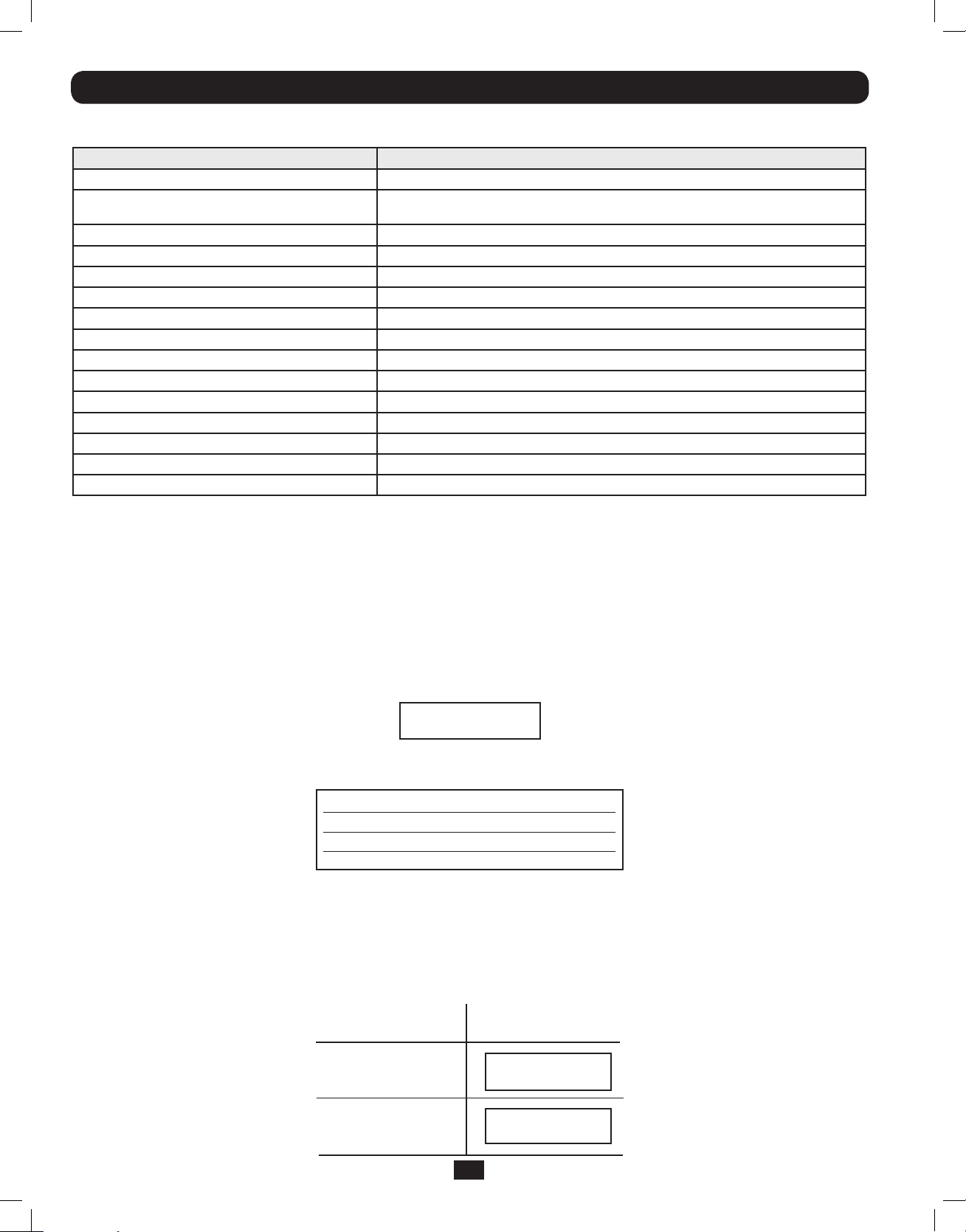
Bypass Messages
While in Bypass Mode, the UPS monitors its input voltage and passes that input power along to connected equipment. The UPS
will not provide battery backup in Bypass Mode.
If the output voltage deviates from an acceptable range (between 15% higher and 20% lower than nominal), the UPS
displays the condition on its LCD and stops supplying output power to its load. If power levels return to an acceptable level,
the UPS resumes supplying power to the load, and its LCD reports that output voltage was too high or too low at one time,
but has returned to nominal.
BYPASS VOLTAGE
CONDITIONS
LCD DISPLAY
MESSAGES
>15% Higher
Than Nominal
>20% Lower
Than Nominal
201207113 933070.indb 26 9/17/2012 1:20:08 PM
BYPS OUT OF VOLT
XXXV / XX.X HZ
BYPS OUT OF VOLT
XXXV / XX.X HZ
26
Page 27
Operation (continued)
Shutdown Messages
Your UPS will shut down and the LCD will display a message if it detects one of the following conditions. Note: During all these
conditions, the “Input,” “Output” and “Bypass” LEDs will be illuminated.
SHUTDOWN
CONDITIONS
Extended
Overload
Output Short
Circuit
Bypass SCR
Short Circuit
Input SCR
Rectier Fails
Inverter Output
Short Circuit
Output SCR Failure
Input Fuse Open
LCD DISPLAY
MESSAGES
SHUT DOWN
OVERLOAD XXX%
SHUT DOWN
O/P SHORT CIRCUIT
SHUT DOWN
BYPASS SCR FAIL
SHUT DOWN
RECTIFIER SCR FAIL
SHUT DOWN
INVERTER FAIL
SHUT DOWN
OUTPUT SCR FAIL
SHUT DOWN
I/P FUSE BROKEN
Output Fuse Open
Parallel Wire
Connection Failure
Internal
Faults
SHUT DOWN
O/P FUSE BROKEN
SHUT DOWN
PARALLEL FAULT
SHUT DOWN
+ DC BUS HIGH
SHUT DOWN
+ DC BUS LOW
SHUT DOWN
- DC BUS HIGH
SHUT DOWN
- DC BUS LOW
SHUT DOWN
BUS OVP FAIL
SHUT DOWN
OVERTEMPERATURE
27
201207113 933070.indb 27 9/17/2012 1:20:09 PM
Page 28
Internal Battery Replacement
9
7
Under normal conditions, the original batteries in your UPS will last many years. See Safety section before replacing batteries. The
batteries are designed for hot-swap replacement (i.e. leaving the UPS ON), but some qualified service personnel may wish to
completely turn the UPS OFF and disconnect equipment before proceeding. It is suggested that you remove the batteries before
the installation process.
1
Remove the screws
2
Separate the front bezel
3
Remove the battery connector snap covers. Save
A
which secure the front bezel.
B
from the front panel.
these covers for reuse.
4
Disconnect the battery connectors
C
and remove the
screws D that secure the battery retention bracket in
place.
5
Remove the battery retention bracket
recycle the middle battery pack
6
Remove/recycle the side battery packs
7
Replace the battery packs
8
Re-attach the battery retention bracket
9
Replace the screws
D
F
and
to secure the battery retention
E
and remove/
F
.
G
.
G
.
E
.
bracket in place.
10
Connect the battery connectors
C
. Attach connectors
black-to-black, red-to-red, white-to-white and green-
to-green.
11
Reinstall the battery connector snap covers.
A
1 13
B
2 12
D
12
Replace the front bezel
13
Replace the screws
place.
B
.
A
to secure the front bezel in
C
4
5
G
D
-10
F
E
-8
G
6 7
28
201207113 933070.indb 28 9/17/2012 1:20:10 PM
Page 29

Storage and Service
Storage
Before storing your UPS, turn it completely OFF. If you store your UPS for an extended period of time, recharge the UPS batteries
for 4 to 6 hours once every three months. Note: after you connect the UPS to utility power, it will automatically begin charging its
batteries. If you leave your UPS batteries discharged for an extended period of time, they will suffer a permanent loss of capacity.
Service
Your Tripp Lite product is covered by the warranty described in this manual. A variety of Extended Warranty and On-Site Service
Programs are also available from Tripp Lite. For more information on service, visit www.tripplite.com/support. Before returning your
product for service, follow these steps:
1. Review the installation and operation procedures in this manual to insure that the service problem does not originate from a
misreading of the instructions.
2. If the problem continues, do not contact or return the product to the dealer. Instead, visit www.tripplite.com/support.
3. If the problem requires service, visit www.tripplite.com/support and click the Product Returns link. From here you can request a
Returned Material Authorization (RMA) number, which is required for service. This simple on-line form will ask for your unit’s model
and serial numbers, along with other general purchaser information. The RMA number, along with shipping instructions will be
emailed to you. Any damages (direct, indirect, special or consequential) to the product incurred during shipment to Tripp Lite or an
authorized Tripp Lite service center is not covered under warranty. Products shipped to Tripp Lite or an authorized Tripp Lite service
center must have transportation charges prepaid. Mark the RMA number on the outside of the package. If the product is within its
warranty period, enclose a copy of your sales receipt. Return the product for service using an insured carrier to the address given
to you when you request the RMA.
Warranty
2-Year Limited Warranty
Seller warrants this product, if used in accordance with all applicable instructions, to be free from original defects in material and workmanship for a period of 2 years (except
internal UPS system batteries outside USA and Canada, 1 year) from the date of initial purchase. If the product should prove defective in material or workmanship within that
period, Seller will repair or replace the product, in its sole discretion. Service under this Warranty can only be obtained by your delivering or shipping the product (with all shipping
or delivery charges prepaid) to: Tripp Lite; 1111 W.35th Street; Chicago IL 60609; USA.Seller will pay return shipping charges. Visit www.tripplite.com/support before sending any
equipment back for repair.
THIS WARRANTY DOES NOT APPLY TO NORMAL WEAR OR TO DAMAGE RESULTING FROM ACCIDENT, MISUSE, ABUSE OR NEGLECT. SELLER MAKES NO EXPRESS WARRANTIES
OTHER THAN THE WARRANTY EXPRESSLY SET FORTH HEREIN. EXCEPT TO THE EXTENT PROHIBITED BY APPLICABLE LAW, ALL IMPLIED WARRANTIES, INCLUDING ALL
WARRANTIES OF MERCHANTABILITY OR FITNESS, ARE LIMITED IN DURATION TO THE WARRANTY PERIOD SET FORTH ABOVE; AND THIS WARRANTY EXPRESSLY EXCLUDES ALL
INCIDENTAL AND CONSEQUENTIAL DAMAGES. (Some states do not allow limitations on how long an implied warranty lasts, and some states do not allow the exclusion or
limitation of incidental or consequential damages, so the above limitations or exclusions may not apply to you. This Warranty gives you specific legal rights, and you may have
other rights which vary from jurisdiction to jurisdiction).
Tripp Lite; 1111 W.35th Street; Chicage IL 60609; USA
WARNING: The individual user should take care to determine prior to use whether this device is suitable, adequate or safe for the use intended. Since individual applications are
subject to great variation, the manufacturer makes no representation or warranty as to the suitability or fitness of these devices for any specific application.
WARRANTY REGISTRATION
Visit www.tripplite.com/warranty today to register the warranty for your new Tripp Lite product. You’ll be automatically entered into a drawing for a chance to win a FREE
Tripp Lite product!* * No purchase necessary. Void where prohibited. Some restrictions apply. See website for details.
Regulatory Compliance Identification Numbers
For the purpose of regulatory compliance certifications and identification, your Tripp Lite product has been assigned a unique series number. The series number can be found on
the product nameplate label, along with all required approval markings and information. When requesting compliance information for this product, always refer to the series
number. The series number should not be confused with the marking name or model number of the product.
WEEE Compliance Information for Tripp Lite Customers and Recyclers (European Union)
Under the Waste Electrical and Electronic Equipment (WEEE) Directive and implementing regulations, when customers buy new electrical and electronic equipment from Tripp Lite
they are entitled to:
• Send old equipment for recycling on a one-for-one, like-for-like basis (this varies depending on the country)
• Send the new equipment back for recycling when this ultimately becomes waste
Tripp Lite follows a policy of continuous improvement. Product specifications are subject to change without notice.
1111 W. 35th Street, Chicago, IL 60609 USA • www.tripplite.com/support
29
201207113 933070.indb 29 9/17/2012 1:20:11 PM
201207113•933070-ENRevC
Page 30

Manual del propietario
SmartOnline™
Monofásico 5kVA–6kVA
Sistemas UPS en línea inteligentes (para montar en rack/torre)
• Incluye el sistema UPS con sistema de baterías internas (5&6kVA), PDU desmontable y módulos PDU
paralelos desmontables (6kVA) • Adaptable para montar en rack y en torre
No es adecuado para aplicaciones móviles
Instrucciones de seguridad importantes 31
Montaje 32
Características 33
Conexión 38
Conexión opcional 41
Operación de derivación manual 43
Funcionamiento 44
Reemplazo de la batería interna 57
Almacenamiento y mantenimiento 58
Garantía 58
English 1
Français 59
Русский 88
1111 W. 35th Street, Chicago, IL 60609 USA • www.tripplite.com/support
Copyright © 2012 Tripp Lite.Todos los derechos reservados. SmartOnline es una marca registrada de Tripp Lite.
201207113 933070.indb 30 9/17/2012 1:20:12 PM
Page 31

Instrucciones de seguridad importantes
GUARDE ESTAS INSTRUCCIONES Este manual contiene instrucciones y advertencias importantes que deben seguirse durante la instalación y el
mantenimiento de este producto. La falta de observar estas advertencias podría afectar su garantía.
Advertencias de ubicación del UPS
• Instale el UPS en una zona estructuralmente sana. El UPS es extremadamente pesado, tenga cuidado al mover y elevar la unidad.
• Opere el UPS únicamente en temperatura ambiente interior entre 32° y 104 °F (0 °C y 40° C). Para obtener los mejores resultados, mantenga la
temperatura interior entre 62 °F y 84 °F (17 °C y 29 °C).
• Deje espacio suficiente alrededor del sistema UPS para una ventilación adecuada.
• No coloque el UPS cerca de medios de almacenamiento magnéticos, podría causar corrupción de datos.
• No monte la unidad con el panel frontal o trasero orientado hacia abajo (en cualquier ángulo). Si la monta de esta manera inhibirá
gravemente la capacidad de enfriamiento interno de la unidad, lo que eventualmente provocará daños en el producto no cubiertos
por la garantía.
Advertencias de conexión del UPS
• Aísle el UPS antes de trabajar en su circuito.
• El suministro de energía de la unidad debe
estar clasificado como monofásico según la
placa de identificación del equipo. También
debe estar adecuadamente conectada a tierra.
Advertencias de conexión del
equipo
• No se recomienda usar este equipo en
aplicaciones de mantenimiento artificial de la vida, donde se puede esperar razonablemente
Dispositivos de protección requeridos y cortes transversales del cable
Protección recomendada para contracorriente.
UPS Power Rating Upstream Circuit Breaker
5kVA N/A
6kVAC curve - 40A
2 poles circuit breaker
GL1
L2(N)
L1
L2(N)
To UPS Nor mal AC source
External power
distribution unit
Q
L
N
UPS
T
B
L
N
que su falla cause la falla del equipo de mantenimiento de la vida o que afecte de manera
importante su seguridad o eficiencia. No use este equipo en presencia de mezclas anestésicas
inflamables con aire, oxígeno u óxido nitroso.
• Conecte el terminal de conexión a tierra del módulo de potencia del UPS a un conductor de
electrodos de conexión a tierra.
Legend
B—Contactor solenoid.
Q—Mains input thermal-magnetic switch.
T—Two-pole contactor 100 A AC1; coil voltage: according to the mains input.
Remark: Q needs to use the approved component of Safety Certification.
• El UPS está conectado a una fuente de alimentación CC (batería). Las terminales de salida pueden tener corriente aún cuando el sistema de
UPS no esté conectado a una fuente de CA.
Advertencias de mantenimiento
• El módulo de potencia y los módulos de batería del UPS no requieren mantenimiento de rutina. No los abra bajo ninguna circunstancia. No tiene
partes internas que el usuario pueda reparar.
Advertencias sobre las baterías
• Conecte sólo módulos de batería de Tripp Lite (del tipo y voltaje correctos) al conector de batería externo del módulo de potencia.
• Las baterías pueden presentar el riesgo de descargas eléctricas y de causar quemaduras por cortocircuitos de alta tensión. Tome las
precauciones necesarias. No deseche las baterías en el fuego. No abra el UPS ni las baterías. No haga cortocircuito ni puente en los terminales
de la batería con ningún objeto. Antes de cambiar la batería, desenchufe y apague el UPS. Utilice herramientas con mangos aislados. Dentro
del UPS no hay partes que el usuario pueda reparar. El reemplazo de baterías debe hacerlo sólo el personal de servicio autorizado utilizando
el mismo número y tipo de baterías (de ácido de plomo selladas). Las baterías se pueden reciclar. Consulte las normas locales para obtener
los requisitos de desecho o visite www.tripplite.com/UPSbatteryrecycling para observar la información de reciclado. Tripp Lite ofrece una línea
completa de Cartuchos de baterías de reemplazo (R.B.C.) para sistemas UPS. Visite Tripp Lite en la Web en www.tripplite.com/support/battery/
index.cfm para buscar la batería de reemplazo específica para su UPS.
• Los fusibles deben ser reemplazados sólo por personal autorizado por la fábrica. Los fusibles dañados sólo deben reemplazarse por fusibles del
mismo número y tipo.
• Sólo personal capacitado debe llevar a cabo el mantenimiento y la reparación. Antes de cualquier trabajo de mantenimiento realizado en
módulos de potencia conectados permanentemente, deben apagarse o derivarse manualmente mediante un transformador. Antes de realizar el
mantenimiento en módulos de potencia que se conecten directamente a tomacorrientes de pared, deben apagarse y desenchufarse. Tenga en
cuenta que existen voltajes potencialmente mortales dentro de la unidad siempre que el suministro de la batería esté conectado.
• No conecte ni desconecte los módulos de baterías mientras el UPS esté funcionando por el suministro de la batería, o cuando el módulo del
transformador no esté en modo de derivación (si el sistema UPS incluye un módulo de transformador con un interruptor de derivación).
• Durante el reemplazo del módulo de baterías “en funcionamiento”, el UPS no podrá proporcionar respaldo de baterías en el caso de un apagón.
• Conecte sólo módulos de baterías compatibles.
31
201207113 933070.indb 31 9/17/2012 1:20:12 PM
Page 32

Montaje
Monte el equipo en un rack de bastidor o rack de 2 ó 4 puestos. El usuario debe determinar la aptitud de las herramientas y los pasos antes de
montarlo. Si las herramientas o los procedimientos no son adecuados para la aplicación, comuníquese con el fabricante del rack o del rack de
bastidor. Las instrucciones de este manual son para racks comunes y racks de bastidor y pueden no ser adecuadas para todas las aplicaciones.
4-Tras el montaje
Los pasadores plásticos incluidos
1
montaje en rack
mientras instala las herramientas de montaje permanente. Inserte un pasador
B
cerca del centro del soporte frontal y trasero de cada estante como se muestra en la imagen.
(Cada soporte frontal posee 6 orificios y cada soporte trasero posee 3 orificios). Los pasadores se
ajustarán en su lugar.
Tras instalar los pasadores, expanda cada estante para que coincidan con la profundidad de los
rieles del rack. Los pasadores pasarán a través de los orificios cuadrados en los rieles del rack
para soportar los estantes. Consulte las etiquetas de la unidad del rack para confirmar que los
estantes estén nivelados en todas las direcciones. Nota: El borde del soporte de cada estante
debe estar orientado hacia adentro.
Asegure los estantes
2
arandelas cóncavas
a los rieles de montaje en forma permanente mediante los tornillos y
B
incluidos como se muestra en la figura.
C
• Para montajes de equipos en 4U, coloque 6 tornillos en total en la parte frontal y 4 tornillos
en total en la parte trasera. Apriete todos los tornillos antes de continuar.
Advertencia: No intente instalar el equipo hasta que haya insertado y ajustado los torni-
llos necesarios. Los pasadores plásticos no soportarán el peso del equipo.
Una las orejas de montaje
3
D
utilizando los tornillos suministrados
Nota: Antes de la instalación, es recomendable retirar las baterías internas del UPS. Esto
eliminará el peso excesivo y permitirá un manejo más seguro del equipo. Consulte la sección de
Reemplazo de la Batería Interna, para las instrucciones del remplazo de la batería.
soportarán en forma temporal a los estantes vacíos del
A
a los orificios de montaje de la parte frontal del equipo
. Las orejas deben estar hacia el frente.
F
B
A
A
B
A
1
B
C
C
B
2
E
E
Con la ayuda de un asistente, eleve el equipo y deslícelo en los estantes de montaje. Una el
4
equipo al rack pasando los tornillos, las tuercas y las arandelas (suministrados por el usuario)
a través de las orejas de montaje y en los rieles del rack. Asegúrese de utilizar rieles de rack
G
3
D
F
individuales para cada componente.
G
4
Configuración para UPS de 12kVA —SU12KRT4UHW Únicamente
(Usando 2 Módulos de Potencia de 6kVA)
Consulte el manual incluido con el PDU paralelo para la instalación del SU12KRT4UHW.
SW
SW
14
14
2-Tras el montaje (Opcional)
Para instalar su UPS de 5kVA ó 6kVA en un rack de 2 postes, debe adquirir un Kit para instalación en Rack de 2 Postes de Tripp Lite (modelo:
2POSTRMKITHD, se vende por separado) por cada módulo de potencia y módulo de baterías instalado. Consulte el manual del propietario del Kit
de instalación para obtener las instrucciones completas de montaje.
Nota: No se recomienda la instalación en 2 postes para sistemas UPS de 12kVA.
32
201207113 933070.indb 32 9/17/2012 1:20:14 PM
Page 33

Montaje
Montaje en torre
Para instalar el UPS en una posición vertical (En torre), se requiere el accesorio 2-9USTAND de
Tripp Lite (se vende por separado).
Una vez instalado, gire el Panel de Control del módulo de potencia para una visualización más
fácil mientras el UPS esté en posición vertical. Inserte un desatornillador pequeño, u otra
herramienta, en las ranuras en cualquier lado del Panel de Control. Extraiga el panel, gírelo, e
inserte el panel de nuevo en su sitio.
Características
Antes de instalar y hacer funcionar el UPS, debe familiarizarse con la ubicación y función de las características de cada componente.
11
2
10 79 68
1
3 4 5
Controles del panel frontal del módulo de potencia
PANTALLA LCD: La pantalla de matriz de puntos (16 × 2 caracteres) con luz de fondo indica
1
una amplia gama de condiciones de funcionamiento del UPS y datos de diagnóstico. También
muestra la configuración y opciones del UPS cuando está en modo de configuración.
BOTÓN ON/MUTE (Encendido/Silencio): Pulse este botón y manténgalo pulsado para
2
escuchar un pitido que enciende el inversor del sistema UPS. Si suena la alarma de la
batería del UPS, pulse este botón para silenciarla.
BOTÓN SCROLL DOWN/EXIT SETUP (Desplazar hacia abajo/Salir de la configuración):
3
Este botón permite examinar distintas opciones y lecturas de energía en la pantalla LCD.
Si lo pulsa momentáneamente, el LCD mostrará una lectura de energía distinta (consulte
“Funcionamiento”). Si lo pulsa junto con el botón SCROLL UP (Desplazarse hacia arriba),
el UPS se colocará en modo de configuración, y este botón se utilizará para desplazarse a
través de las opciones de configuración y salir de este modo.
BOTÓN SCROLL UP/SELECT (Desplazarse hacia arriba/Seleccionar): Este botón
4
permite examinar distintas opciones y lecturas de energía en la pantalla LCD. Si lo
pulsa momentáneamente, el LCD mostrará una lectura de energía distinta (consulte
“Funcionamiento”). Si lo pulsa junto al botón SCROLL DOWN, el UPS se colocará en modo de
configuración, y este botón se utilizará para seleccionar las opciones de configuración.
BOTÓN OFF (Apagado): Pulse este botón hasta escuchar un bip que apaga el inversor del sistema UPS.
5
LED DE O/P (OUTPUT) (Salida): Esta luz verde se iluminará para indicar que el UPS está suministrando alimentación CA a los equipos
6
conectados.
LED DE CC/CA (INVERTER) (Inversor): Esta luz verde se iluminará para indicar que se activó el inversor CC/CA del UPS.
7
LED DE BYPASS (Derivación): Esta luz amarilla destellará cuando el UPS proporcione alimentación de la red pública filtrada sin encender
8
el convertidor o el inversor. Si destella este LED, los equipos conectados no recibirán energía de la batería en caso de un apagón. Si está
activado el Modo Económico, este LED estará encendido permanentemente y los equipos conectados recibirán energía en caso de un apagón.
LED DE CA/CC (Converter) (Conversor): Esta luz verde se iluminará para indicar que el conversor CA/CC del UPS está cargando los módulos
9
de baterías conectados.
LED BATTERY (Batería): Esta luz verde se iluminará cuando el UPS esté descargando la batería para proporcionar alimentación CA a los
10
equipos conectados. Sonará una alarma, que puede silenciarse con el botón ON/MUTE. Este LED permanecerá iluminado hasta que se silencie
la alarma.
LED DE I/P (INPUT) (Entrada): Esta luz verde se iluminará para indicar que existe un suministro de entrada de CA.
11
33
201207113 933070.indb 33 9/17/2012 1:20:15 PM
Page 34

Características (Panel trasero)
Consulte la sección “Características (Panel trasero)” para observar las descripciones de la característica
SU5000RT4UHV—Sistema UPS 5kVA
9
10
11
12
PARALLEL
EPO
1
RS-232
RS-232
USB
1
OUTPUT 2
200-240Vac
BREAKER 20A
13
BATTERY
CABLE UNDER LOAD.
DO NOT DISCONNECT
CAUTION:
CONNECTOR
192VDC
BATTERY
ACC. SLOT
OUTPUT 1
30A
200-240Vac
AC INPUT
8 7 4
6 3
SU6000RT4UHV—Sistema UPS 6kVA con PDU NEMA
9
10
11
RS-232
RS-232
USB
PARALLEL
12
EPO
13
ACC. SLOT
1
NORMAL
14
8 6 5 4 37
SU6000RT4UHVHW—Sistema UPS 6kVA con PDU conectada permanente
9
10
11
RS-232
PARALLEL
12
EPO
13
ACC. SLOT
BY
PASS
RS-232
USB
1
NORMAL
BY
PASS
16 15 4 5
34
201207113 933070.indb 34 9/17/2012 1:20:17 PM
2
Page 35

Características (Panel trasero)
Consulte la sección “Características (Panel trasero)” para observar las descripciones de la característica
SU6000RT4UHVG—Sistema UPS 6kVA con PDU IEC
9
10 11 12 13
RS-232
RS-232
USB
1
4 21 217 7 5 15
SU12KRT4UHW—Sistema de UPS de 12kVA y Módulos PDU paralelos
Nota: Para las instrucciones de instalación, configuración y puesta a punto del sistema de 12kVA, consulte el manual incluido con el
PDU Paralelo.
9
RS-232
PARALLEL
PARALLEL
EPO
NORMAL
BY
PASS
20
EPO
19 18 17 1610 11 12 13
15
2
11
RS-232
USB
1
2
RS-232
RS-232
4
USB
PARALLEL
EPO
22
23
4
20
18
17
35
201207113 933070.indb 35 9/17/2012 1:20:18 PM
Page 36

Características (Panel trasero)
SU6000RT4UTFHW—UPS de 6kVA con PDU Con Instalación Eléctrica Permanentemente y
Transformador Reductor de Aislamiento de 6kVA (SU6000XFMR2U)
24 24
8
14
12
11
10
9
RS-232
RS-232
USB
PARALLEL
EPO
ACC. SLOT
1
NORMAL
25
13
PASS
BY
2
16 15 4 5
SU6000RT4UTF—UPS de 6kVA con PDU NEMA y Transformador de Aislamiento de 6kVA
24 24
8
14
12
11
10
9
RS-232
RS-232
USB
PARALLEL
EPO
ACC. SLOT
1
25
13
NORMAL
BY
PASS
14
8 6 5 4 37
36
201207113 933070.indb 36 9/17/2012 1:20:24 PM
Page 37

Características (Panel trasero)
Sistema UPS: Esta unidad redundante aloja la alimentación del sistema UPS y los componentes de control, junto con las baterías internas.
1
Unidad de distribución de energía (PDU) independiente y desmontable: Esta unidad redundante aloja los componentes de entrada y
2
salida del UPS, junto con el interruptor de derivación. Cuando el interruptor se establece en derivación, la PDU puede extraerse
completamente del módulo de potencia/batería para el mantenimiento de rutina de alimentación/batería sin interrumpir la alimentación a las
cargas conectadas. Mientras este interruptor esté establecido en derivación, los equipos conectados recibirán energía de CA de la red pública
sin filtrar pero, en caso de un apagón, no recibirán energía de batería.
Cable de entrada CA: Se conecta directamente a un receptáculo de pared que proporcione 200-240V de alimentación CA de la energía del
3
servicio.
Conector de la batería externa: Utilícelo para conectar uno o más módulos de baterías de Tripp Lite al módulo de potencia. Extraiga
4
la cubierta para obtener acceso. El módulo de potencia no se iniciará sin una conexión al módulo de batería cargado. Consulte el Manual del
propietario del módulo de la batería para obtener las instrucciones de conexión y las advertencias de seguridad.
Interruptor de derivación de mantenimiento: Este interruptor permite al personal de servicio calificado retirar la PDU desmontable del
5
módulo de potencia/batería para realizar el mantenimiento de rutina sin interrumpir la energía a las cargas conectadas. Mientras este
interruptor esté establecido en derivación, los equipos conectados recibirán energía de CA de la red pública filtrada pero, en caso de un
apagón, no recibirán energía de batería. Consulte la sección “Operación de derivación manual” para ver todo el procedimiento de derivación.
Receptáculos de salida CA L6-30R: Aceptan conexión directa de los enchufes L6-30 NEMA de los equipos.
6
Disyuntor de salida 20A: Un disyuntor de dos polos controla la alimentación de salida de los receptáculos indicados en cada modelo.
7
Receptáculos de salida CA L6-20R: Aceptan conexión directa de los enchufes L6-20 NEMA de los equipos.
8
Puerto de comunicación RS-232: El puerto serial DB9 hembra puede utilizarse para conectar el UPS a una estación de trabajo o servidor.
9
Utiliza el protocolo RS-232 para comunicarse con el ordenador conectado. Se utiliza con el software de Tripp Lite y el cable serial incluido
para monitorear y administrar el UPS en forma remota a través de una red y para guardar archivos abiertos automáticamente y apagar el
equipo en caso de un apagón. Consulte la sección “Conexión opcional” para obtener detalles.
Miniranura: Conector USB (desactivado en forma predeterminada—interruptores DIP en la posición RS-232. Para activarlo, mueva los dos
10
interruptores DIP a la posición USB). En caso de ser necesario, se encuentra disponible una tarjeta de cierre de contactos opcional (N.º de
pieza Tripp Lite RELAYIOMINI).
Conector paralelo: Para la comunicación en paralelo del UPS (funciona sólo en el modelo 6kVA). Consulte el manual proporcionado con el
11
juego de PDU Paralelo. Para obtener más información, visite www.tripplite.com/support.
Puerto EPO (Apagado de emergencia): El módulo de potencia cuenta con un puerto EPO que puede utilizarse para conectar el módulo
12
de potencia a un interruptor de cierre de contacto para habilitar el apagado de emergencia. Consulte la sección “Conexión opcional” para
obtener detalles.
Ranura para accesorios: Extraiga el pequeño panel de la cubierta para instalar accesorios opcionales para controlar y monitorear el
13
sistema UPS en forma remota. Visite Tripp Lite en la Web (www.tripplite.com) para conocer los productos de SNMP, administración de red y
conectividad disponibles que pueden instalarse en esta ranura.
Bloque de Terminales de Entrada/Salida del Transformador de CA (sólo en UPS 6kVA): Utilice este terminal para lograr una interfaz con
14
un sistema PDU aprobado.
Bloque de terminales de entrada de la red pública (sólo en UPS 6kVA y en módulos 12kVA IEC/PARALELO/PERMANENTE): Utilice
15
estos terminales para conectar el módulo de potencia a la red pública. Para acceder al bloque, desatornille y retire la tapa por encima.
Bloque de terminales de salida de los equipos (sólo en UPS 6kVA y en módulos 12kVA IEC/PARALELO/PERMANENTE): Utilice estos
16
terminales para conectar el módulo de potencia a los equipos. Para acceder al bloque, desatornille y retire la tapa por encima.
Disyuntor de entrada CA: Un disyuntor de dos polos controla la alimentación de entrada al módulo de potencia.
17
18
Interconexión de alimentación paralela: Sólo para utilizar con PDU paralela secundaria.
19
Disyuntor de mantenimiento (Sólo UPS de 12kVA): controla el mantenimiento del UPS.
20
Disyuntor de salida CA: Un interruptor automático de dos polos proporciona rodeo para el sistema paralelo hacia la carga.
21
Receptáculos de salida CA (sólo en módulo PDU 6kVA UPS/ IEC): Acepta conexión directa de los enchufes IEC-320-C20 de los equipos.
22
Módulo Secundario de UPS
23
Módulo Secundario de PDU
24
Tomacorrientes de CA 5-15/20R: Acepta la conexión directa de clavijas NEMA 5-15P ó 5-20P de los equipos.
25
Transformador Reductor de Aislamiento: Esta unidad autónoma proporciona un medio para conectar dispositivos tanto de bajo voltaje
como de alto voltaje al sistema UPS.
37
201207113 933070.indb 37 9/17/2012 1:20:24 PM
Page 38

Conexión
Nota: El voltaje de salida se establece en 208~(predeterminado) en la fábrica. Si desea cambiar el voltaje de salida del UPS,
consulte “Selección del voltaje de salida” de la sección “Funcionamiento”. Debe seleccionar el voltaje de salida correcto antes de
conectar los equipos al UPS.
1
Conecte el cable de entrada del UPS al tomacorriente eléctrico.
(SU5000RT4UHV, SU5000RT4UTF, SU6000RT4UHV, SU6000RT4UTF)
El UPS debe estar conectado a un circuito dedicado de amperaje suficiente.
Nota! Después de conectar el UPS a una fuente activa de CA, el LCD del UPS mostrará “BYPASS
MODE” (modo de rodeo) y cargará automáticamente sus baterías mientras proporciona energía
en la salida.
Si tiene un PDU con rodeo manual, coloque el interruptor de rodeo del PDU en “NORMAL”.
1
2
Encienda el UPS
Pulse el botón “ON” del UPS hasta oír un pitido para comenzar la operación del inversor. El UPS
un breve autotest y mostrará el resultado en la pantalla LCD. Consulte “Inicio del autotest” de la
sección “Funcionamiento” para ver la secuencia de visualización. Su UPS proporcionará ahora
energía filtrada a la salida de CA.
Nota: El sistema UPS funcionará adecuadamente desde la puesta en marcha inicial, no obstante,
la autonomía máxima de la batería de la unidad solo se alcanzará después de que se haya
cargado durante 24 horas.
3
Conecte los equipos al UPS.
El UPS está diseñado para admitir equipos electrónicos únicamente. El UPS se sobrecargará si
el valor nominal de VA total para todos los equipos conectados excede la capacidad de salida del
UPS. No conecte aplicaciones domésticas o impresoras láser a los tomacorrientes del UPS. Para
verificar los valores de VA, busque en las placas de identificación. Si el equipo está numerado
en amperios, multiplique el número de amperios por el voltaje de entrada (200V~240V) para
determinar el VA. (Ejemplo: 1 amp x 208V = 208VA).
2
4
Apague el UPS (Opcional)
Pulse el botón “OFF” del UPS hasta sentir un pitido. Se le presentará la opción Sí/No.
Seleccione Sí para apagar la UPS. Seleccione No para cancelar. El UPS continuará cargando
automáticamente sus baterías y proporcionando CA sin filtrar derivada [BYPASSED] mientras
esté presente la entrada de energía de CA. Para desactivar completamente el UPS, desconecte
el cable de entrada del UPS cuando el sistema esté en modo de espera.
5
Arranque en frío del UPS (Opcional)
Para utilizar el UPS como una fuente de alimentación independiente cuando no hay alimentación de entrada CA (por ejemplo, durante un apagón),
puede “arrancar en frío” el UPS y los equipos conectados desde la batería del UPS. La batería del UPS debe estar cargada al menos parcialmente
para realizar esta operación correctamente. Pulse y mantenga presionado el botón “ON” hasta escuchar un pitido para arrancar en frío el UPS. La
pantalla LCD mostrará ON BATTERY MODE (En modo de batería). Comenzará a descargarse la energía de la batería. Es posible que algunos equipos
electrónicos consuman más amperios durante el arranque; cuando arranque en frío, considere reducir la carga inicial en el sistema de UPS.
3
Conexiones de entrada de la barra de terminales
(SU6000RT4UHVHW, SU6000RT4UHVG, SU6000RT4UTFHW)
Nota: Para información sobre la Instalación Eléctrica Permanente de SU12KRT4UHW, consulte el manual incluido con el PDU Paralelo.
Precauciones al realizar una instalación eléctrica permanente
• El cableado debe tenderlo un electricista calificado.
• Cuando se realicen las conexiones del cableado, cerciórese de cumplir en todo momento con las regulaciones correspondientes de su zona (por
ej. National Electrical Code (NEC), en los EE. UU.). Asegúrese también de instalar un interruptor para desconexión que sea de fácil acceso, de
manera tal que pueda cortar la entrada de CA al UPS durante incendios y otras emergencias. Asegúrese de que todos los cables poseen funda y
que están asegurados por sujetadores de conexión. Ajuste las conexiones con un torque no inferior a 24-28 pulgadas/libra (2,7-3,2 NM).
• Cerciórese de que su equipo cuenta con la conexión a tierra apropiada.
• El uso de cables del calibre incorrecto puede dañar el equipo y causar incendios. Elija el cableado y los circuitos de protección apropiados para
realizar las conexiones. Los conductores a tierra tienen que ser del mismo calibre y tipo que los conductores de potencia.
• Consulte las directivas del National Electrical Code (NEC) para los requisitos de calibre de cableado y circuito de protección de salida
apropiados.
38
201207113 933070.indb 38 9/17/2012 1:20:25 PM
Page 39

Conexión (continuación)
Conexión de la banda de terminales-Módulo de
PDU IEC (SU6000RT4UHVG)
Modelo
SUPDMB6KIEC200~240V(L-N)30A 8 mm
1
Desatornille los tres tornillos para extraer la cubierta de la
Voltaje de en-
trada
Corrientede
entrada máxima
calificada
Tamaño de cable
típico
2
banda de terminales y deslice hacia afuera como se muestra
en el diagrama 1.
2
Conecte los cables L1, L2 y de conexión a tierra (Entrada de
conexión permanente, Salida de receptáculo) de acuerdo a las
marcas de los conectores como se muestra en el diagrama 2.
3
Deslice hacia adentro y vuelva a unir la cubierta de la banda
de terminales con los tres tornillos del Paso 1.
1
2
3
4
Una la PDU al sistema UPS utilizando 4 tornillos como se
muestra en el diagrama 4.
4
Conexión de la banda de terminales—Módulos de PDU de conexión permanente
(SU6000RT4UHVHW, SU6000RT4UTHFHW)
Modelo Voltaje de entrada
SUPDMB6KHW 200~240V(L-N)32A 30A 8 mm
1
Desatornille los tres tornillos para extraer la cubierta de la banda
Corrientede
entrada máxima
calificada
de terminales y deslice hacia afuera como se muestra en el
diagrama 1.
Corrientede
salida máxima
calificada
Tamaño de cable
típico
2
1
39
201207113 933070.indb 39 9/17/2012 1:20:27 PM
Page 40

Conexión (continuación)
2
Conecte los dos conjuntos de cables L1, L2 y de conexión a
tierra (1 entrada, 1 salida) según las marcas en los conectores
como se muestra en el diagrama 2. Asegúrese de conectar un
conjunto de cables a los terminales de entrada y el otro a los
terminales de salida.
3
Deslice hacia adentro y vuelva a unir la cubierta de la banda
de terminales con los 3 tornillos del Paso 1.
4
Una la PDU al sistema UPS utilizando 4 tornillos como se
muestra en el diagrama 4.
2
3
4
Instalación Eléctrica Permanente del Arnés del Transformador (Entrada/Salida)
SU6000RT4UTF
1. Enchufe el XFMR en el UPS.
2. Conecte el transformador al UPS. Ésta puede ser una
conexión mediante una Instalación Eléctrica permanente,
conexión de tomacorrientes o ambas, previendo que la
carga conectada no exceda la capacidad.
SU12KRT4UHW
Para la conexión, puesta a punto e instalación, consulte el
manual incluido con el PDU Paralelo.
L1 G L2 L G N N G L
208 / 240V
Input
Set Front Panel Selector Switch to Proper Voltage Before Making Connections
120V
Output
Branch A
120V
Output
Branch B
40
201207113 933070.indb 40 9/17/2012 1:20:28 PM
Page 41

Conexión opcional
Las siguientes conexiones son opcionales. El sistema UPS funcionará correctamente sin estas conexiones.
1
Conexiones de comunicación serial y USB RS-232
Utilice el cable incluido para conectar el puerto “RS-232” del módulo de potencia al puerto de
comunicación del ordenador. Esto permitirá el control y monitoreo de red totales del sistema
UPS. Instale el software PowerAlert de Tripp Lite en su ordenador, según el sistema operativo
instalado. El UPS también está equipado con un módulo de comunicación USB.
En caso de ser necesario, se encuentra disponible un módulo de cierre de contactos
alternativo (N.º de pieza Tripp Lite RELAYIOMINI). De manera predeterminada, este módulo
está deshabilitado. Para habilitarlo, mueva los interruptores DIP a la posición USB. Si habilita
este módulo, se deshabilita el puerto RS-232. El puerto RS-232 también se desactiva con la
instalación de una tarjeta SNMP/Web opcional (N.º de pieza de Tripp Lite SNMPWEBCARD). La
tarjeta SNMP/Web puede utilizarse en forma simultánea con el módulo de comunicación USB.
2
Conexión del puerto EPO
Esta característica opcional es únicamente para aquellas aplicaciones que requieran conexión a
un circuito de Apagado de Emergencia (EPO) de la instalación. Cuando se conecta el UPS a
este circuito, permite el apagado de emergencia del inversor del UPS e inhibe la transferencia a
un rodeo interno. Usando el cable proporcionado, conecte el puerto EPO de su UPS (ver
un interruptor, proporcionado por el usuario, normalmente abierto de acuerdo con el diagrama
de circuito (ver 2b).
2a
) a
1
2a
Conector EPO
Para activar el EPO pueden ponerse en corto
las terminales 4 y 5 ó las terminales 2 y 3.
Nota:
1. Si se usa un cable diferente al suministrado, éste no debe exceder 107m [350 pies] o tener una resistencia superior a 10 ohms.
2. Si se usa un interruptor de EPO sin seguro, el interruptor EPO deberá sujetarse por un mínimo de 1 segundo. Esto no aplica a un interruptor
EPO con seguro.
3. Para la configuración de una conexión EPO de un interruptor normalmente cerrado, consulte por favor al Soporte Técnico de Tripp Lite.
PRECAUCIÓN: El puerto EPO no es un supresor de sobretensiones de línea telefónica; no conecte una línea telefónica a este puerto.
Información de EPO
2b
41
201207113 933070.indb 41 9/17/2012 1:20:30 PM
Page 42

Conexión opcional (continuación)
Estado del UPS cuando activa EPO con línea CA presente:
LEDsSalidasVentiladoresSerialSNMPUSB Pantalla LCD
Apagados Apagadas Apagados Apagado Apagado Apagado
Para reiniciar el UPS después que se activa EPO con línea CA presente:
1. Verifique que la activación de EPO se ha eliminado o borrado.
2. Elimine la alimentación de línea CA al UPS.
3. Reconecte la energía de línea CA. Ahora el UPS comenzará el respaldo en el modo de Rodeo,
y la pantalla LCD mostrará “BYPASS MODE” [Modo de Rodeo].
Estado del UPS cuando activa EPO sin línea CA presente:
LEDsSalidasVentiladoresSerialSNMPUSB Pantalla LCD
Apagados Apagadas Apagados Apagado Apagado Apagado
Para reiniciar el UPS después que se activa EPO sin energía de línea CA:
1. Verifique que la activación de EPO se ha eliminado o borrado.
2. Reconecte la alimentación de línea CA al UPS. Ahora el UPS comenzará el respaldo en el
modo de Rodeo y la pantalla LCD mostrará “BYPASS MODE” [Modo de Rodeo].
3
Conexión de batería externa
El UPS contiene un robusto sistema de baterías interno, las baterías externas sólo son
necesarias para extender el tiempo de funcionamiento. Si agrega baterías externas aumentará
el tiempo de recarga y el tiempo de funcionamiento. La ilustración muestra la ubicación del
Conector de baterías externas del UPS, en donde se inserta el cable de módulo de baterías.
Las instrucciones de instalación completas para el módulo de baterías se incluyen en el manual
del propietario del módulo de baterías. Asegúrese de que los cables estén completamente
insertados en los conectores. Pueden provocarse pequeñas chispas durante la conexión de
la batería; esto es normal. No conecte o desconecte módulos de baterías cuando el UPS está
funcionando con alimentación por batería.
“Parada de
Emergencia”
“Parada de
Emergencia”
NORMAL
4
Ranura para accesorios
Extraiga la cubierta de la ranura para instalar una tarjeta para accesorios SNMP/Web interna
opcional (Modelo: SNMPWEBCARD) para monitoreo remoto y control mediante SNMP, Internet
o telnet. (También está disponible la tarjeta RELAYIOCARD de Tripp Lite). Visite www.tripplite.
com/support para obtener más información, incluyendo una lista de productos de SNMP,
administración de red y conectividad disponibles.
3
4
42
201207113 933070.indb 42 9/17/2012 1:20:30 PM
Page 43

Reemplazo Hot-Swap del Módulo de Potencia*
ADVERTENCIA Únicamente para personal de servicio calificado. No seguir el procedimiento de derivación con exactitud causará que el
UPS no se apague adecuadamente, lo que resultará en el riesgo continuo de muerte o lesiones a causa del contacto potencial con alto
voltaje. El UPS y la PDU desmontable son extremadamente pesados. Este procedimiento requiere la participación de varias personas.
El sistema UPS incluye una PDU desmontable, independiente con un interruptor de derivación. Este interruptor permite al personal de servicio
calificado retirar la PDU desmontable del UPS para realizar el mantenimiento de rutina sin interrumpir la energía a las cargas conectadas. Con este
interruptor establecido en “BYPASS”, los equipos conectados recibirán alimentación de la red de servicio público sin filtrar. Pero los equipos no
recibirán energía de la batería en el caso de un apagón.
* Para el rodeo, consulte el manual incluido con el PDU Paralelo SU12KRT4UHW.
Extracción del UPS (Configuraciones Únicamente para Módulo de Potencia de
un Solo UPS de 6kVA)
PASO 1. Inhabilite PowerAlert y desconecte los cables de comunicación SNMP o USB serial de los puertos de comunicación
PASO 2. Si el UPS recibe energía, pulse el botón
C
aparezca en la pantalla LCD
en el frente del módulo de potencia. Se le pedirá que ingrese “BYPASS MODE” [ modo de rodeo].
B
OFF del UPS hasta que escuche un pitido y el mensaje BYPASS MODE (modo de derivación)
Oprima nuevamente el botón “OFF” del UPS para activar el BYPASS MODE”.
PASO 3. Coloque el interruptor de derivación de la PDU
PASO 4. Si hay un módulo de baterías externas
D
en “BYPASS” en la parte posterior del PDU del UPS.
E
conectado al UPS, desconéctelo.
El UPS ahora está apagado de manera segura y puede desconectarse de la PDU para realizar el mantenimiento/reemplazo.
PASO 5. Extraiga los cuatro tornillos que aseguran las orejas de montaje frontales del UPS al rack. Con la PDU aún unida, mueva el sistema
UPS y la PDU hacia adelante en el rack suavemente (aproximadamente 4 pulgadas), asegurándose de que ambos componentes
permanezcan apoyados adecuadamente en los rieles de soporte para montar en rack del UPS.
PASO 6. En la parte trasera del UPS, extraiga los cuatro tornillos que sostienen la PDU desmontable al UPS que se le hace el mantenimiento.
Con un asistente que sostenga la parte frontal del UPS en su lugar, desmonte con cuidado la PDU de la parte trasera del UPS y
colóquela en los rieles de soporte del UPS. Retire el módulo de potencia del UPS del frente del rack.
A
del UPS.
ADVERTENCIA! ¡Alto voltaje! ¡Riesgo de descargas eléctricas!
A
PARALLEL
EPO
RS-232
RS-232
USB
E D
PASOS 1, 3 y 4
NORMAL
C
B
PASO 2
BY
PASS
PASO 5
PASO 6
43
201207113 933070.indb 43 9/17/2012 1:20:31 PM
Page 44

Funcionamiento
Información de la pantlla LED
Modo ONLINE [en línea]: Voltaje de entrada
CA en rango normal: 156-280V.
Modo de derivación: Voltaje de entrada CA
en un rango de: -20 a +15% del voltaje nomi-
nal; modo de derivación habilitado.
Modo económico: Voltaje de entrada CA en
un rango entre -10 y +10% del voltaje nomi-
nal; el Modo económico está habilitado.
IP BYPASS
AC/DCBATTERY DC/AC O/P
Arranque en frío/Modo de batería: Cuando
esté en modo de batería, verá el siguiente
mensaje LED:
IP BYPASS
AC/DC DC/ACBATTERY O/P
IP BYPASS
BATTERY DC/AC O/P
AC/DC
Arranque de la alimentación CA: Con
arranque de la alimentación CA, observará la
siguiente secuencia de LED:
IP BYPASS
AC/DC DC/ACBATTERY O/P
IP BYPASS
Parpadeante
AC/DC
DC/ACBATTERY O/P
IP BYPASS
BATTERY DC/AC
AC/DC O/P
Arranque en frío: Con arranque en frío, ob-
servará la siguiente secuencia de LED:
IP BYPASS
BATTERY
IP BYPASS
BATTERY AC/DC
AC/DC DC/AC O/P
DC/AC O/P
Apagado EPO (Modo de conversión de fre-
cuencia): Con apagado EPO sin alimentación,
observará la siguiente secuencia de LED:
Parpadeante
IP
BATTERY DC/AC
AC/DC O/P
BYPASS
Apagado EPO (Modo CA): Con apagado EPO
y con alimentación CA, observará la siguiente
secuencia de LED:
BYPASSIP
BATTERY DC/ACAC/DC O/P
Modo de Batería Independiente: En el
modo de batería independiente, se mostrará
la misma secuencia de LED que en el modo
ONLINE, pero sonará una “Alarma de Batería
en Mal Estado”.
IP BYPASS
AC/DCBATTERY DC/AC O/P
44
201207113 933070.indb 44 9/17/2012 1:20:33 PM
Page 45

Funcionamiento (continuación)
Inicio del autotest
Cuando se enciende el UPS, ingresará en Modo diagnóstico y realizará un breve autotest que dura casi 15 segundos. Los resultados del autotest
se muestran en la pantalla LCD en la siguiente secuencia.
*Nota: Si se arranca en frío el UPS,
se iluminará el LED de la BATERÍA.
SE INICIÓ CON
ENTRADA CA
MODO DIAGNÓSTICO
FREC. SALIDA = 50Hz
MODO DIAGNÓSTICO
ENTRADA 000V / 00Hz
MODO DIAGNÓSTICO
RECTIFICADOR OK
MODO DIAGNÓSTICO
CARGADOR OK
MODO DIAGNÓSTICO
BATERÍA OK
MODO DIAGNÓSTICO
BUS CC OK
MODO DIAGNÓSTICO
PRUEBA INVERSOR
MODO DIAGNÓSTICO
INVERSOR OK
NIVEL DE CARGA
00.00V / 000%
ARRANQUE
EN FRÍO*
MODO DIAGNÓSTICO
FREC. SALIDA = 50Hz
MODO DIAGNÓSTICO
ENTRADA 000V / 00Hz
MODO DIAGNÓSTICO
RECTIFICADOR OK
MODO DIAGNÓSTICO
BATERÍA OK
MODO DIAGNÓSTICO
BUS CC OK
MODO DIAGNÓSTICO
PRUEBA INVERSOR
MODO DIAGNÓSTICO
INVERSOR OK
NIVEL DE CARGA
00.00KW / 000%
Falló el autotest
Si se detecta un problema durante el autotest, el LCD mostrará un mensaje de error. Si el UPS muestra algunos de estos mensajes en el LCD,
visite www.tripplite.com/support para obtener mantenimiento.
FALLA EN LA BATERÍA
LLAME A MANTENIMIENTO
FALLÓ LA CARGA DE LA
BATERÍA LLAME A
MANTENIMIENTO
F ALLA DE CA/CC
LLAME A MANTENIMIENTO
FALLA DEL INVERSOR
LLAME A MANTENIMIENTO
FALLA DE SALIDA
LLAME A MANTENIMIENTO
FALLA DEL VENTILADOR
LLAME A MANTENIMIENTO
45
201207113 933070.indb 45 9/17/2012 1:20:33 PM
Page 46

Funcionamiento (continuación)
Funcionamiento normal
Durante el funcionamiento normal, la primera línea de la pantalla LCD muestra el modo de operación del UPS: Modo en línea, Modo eco-
nómico, Modo de conversión de frecuencia, Modo de batería, Modo de derivación o Modo paralelo (sólo modelo 12kVA).
Modo en línea: El UPS proporciona alimentación CA mientras la alimentación de la red pública está disponible y cambia a Modo batería en
forma instantánea (tiempo de transferencia cero) si se interrumpe la alimentación CA.
Modo económico: El UPS proporciona alimentación CA a alta eciencia mientras que la alimentación de la red pública esté dentro del +/-
10% voltaje de entrada CA calicado y cambia a Modo batería (tiempo de transferencia de 8 ms) si se interrumpe la alimentación CA.
Modo de conversión de frecuencia: Se utiliza para convertir la frecuencia de entrada del UPS a una frecuencia de salida distinta (es
decir, entrada de 60 HZ a salida de 50 Hz. Nota: Se apagará la salida en Modo de conversión de frecuencia si la unidad se coloca en
derivación).
Modo batería: El UPS proporciona alimentación CA del respaldo de la batería mientras dure la energía de la batería. Vuelve a cambiar a
Modo en línea o económico si la alimentación de la red pública está disponible y se apaga si se acaba la energía de la batería.
Modo de derivación: El UPS proporciona alimentación CA mientras esté disponible la alimentación de la red pública. El UPS se cierra si se
interrumpe la alimentación CA.
Modo paralelo (sólo en el modelo SU12KRT4UHW): El UPS puede proporcionar redundancia de hasta 6kVA o alimentación de hasta
12kVA. Para información adicional, consulte el manual proporcionado con el juego del PDU Paralelo.
La segunda línea de la pantalla LCD muestra las condiciones de alimentación básicas. En todos los modos de funcionamiento puede pul-
sar los botones de SCROLL para examinar las condiciones de alimentación básicas en las secuencias que se muestran a continuación:
Información de la pantalla
Modo en línea:
MODO EN LÍNEA
00.00KW / 000%
INDEPENDIENTE
00.00KVA / 000%
VOLTAJE DE ENTRADA
000V / 00.0Hz
VOLTAJE DE DERIVACIÓN
000V / 00.0Hz
VOLTAJE DE SALIDA
000V / 00.0Hz
CAPACIDAD DE LA BATERÍA
000V / 000%
TIEMPO RESTANTE
0000 MINUTOS
EN LÍNEA 5/6KVA
V00 CV01
Información de la pantalla
Modo económico:
MODO ECONÓMICO
00.00KW / 000%
INDEPENDIENTE
00.00KVA / 000%
VOLTAJE DE ENTRADA
000V / 00.0Hz
VOLTAJE DE DERIVACIÓN
000V / 00.0Hz
VOLTAJE DE SALIDA
000V / 00.0Hz
CAPACIDAD DE LA BATERÍA
000V / 000%
TIEMPO RESTANTE
0000 MINUTOS
EN LÍNEA 5/6KVA
V00 CV01
Información de la pantalla
Modo de conversión de
frecuencia:
MODO CONV. FREC.
00.00KW / 000%
INDEPENDIENTE
00.00KVA / 000%
VOLTAJE DE ENTRADA
000V / 00.0Hz
VOLTAJE DE DERIVACIÓN
000V / 00.0Hz
VOLTAJE DE SALIDA
000V / 00.0Hz
CAPACIDAD DE LA BATERÍA
000V / 000%
TIEMPO RESTANTE
0000 MINUTOS
EN LÍNEA 5/6KVA
V00 CV01
Información de la pantalla
Modo batería:
MODO BATERÍA
00.00KW / 000%
INDEPENDIENTE
00.00KVA / 000%
VOLTAJE DE ENTRADA
000V / 00.0Hz
VOLTAJE DE DERIVACIÓN
000V / 00.0Hz
VOLTAJE DE SALIDA
000V / 00.0Hz
CAPACIDAD DE LA BATERÍA
000V / 000%
TIEMPO RESTANTE
0000 MINUTOS
EN LÍNEA 5/6KVA
V00 CV01
Información de la pantalla
Modo de derivación:
MODO DERIVACIÓN
00.00KW / 000%
INDEPENDIENTE
00.00KVA / 000%
VOLTAJE DE ENTRADA
000V / 00.0Hz
VOLTAJE DE DERIVACIÓN
000V / 00.0Hz
VOLTAJE DE SALIDA
000V / 00.0Hz
CAPACIDAD DE LA BATERÍA
000V / 000%
TIEMPO RESTANTE
0000 MINUTOS
EN LÍNEA 5/6KVA
V00 CV01
46
201207113 933070.indb 46 9/17/2012 1:20:33 PM
Page 47

Funcionamiento (continuación)
Funcionamiento normal
Información de la pantalla Modo
paralelo (sólo modelo 12kVA):
MODO PARALELO
00.00KW / 000%
PARALELO: MAESTRO
00.00KVA / 000%
VOLTAJE DE ENTRADA
000V / 00.0Hz
VOLTAJE DE DERIVACIÓN
000V / 00.0Hz
VOLTAJE DE SALIDA
000V / 00.0Hz
CAPACIDAD DE BATERÍA
000V / 000%
TIEMPO RESTANTE
0000 MINUTOS
EN LÍNEA 6KVA
V00 CV01
NOTA: Cuando se conectan dos unidades en paralelo,
el “UPS Maestro” mostrará “PARALELO: MAESTRO” en
esta segunda pantalla. La pantalla del “UPS Secundario”
mostrará “PARALELO: ESCLAVO”. Si las dos unidades no
se conectan en paralelo correctamente, los dos mostrarán
“INDEPENDIENTE” en esta segunda pantalla.
Menú de configuración del UPS
Pulse los botones HACIA ARRIBA y HACIA ABAJO en forma simultánea durante 3 segundos hasta que aparezca la pantalla del MENÚ DE CONFIGU-
RACIÓN como se muestra a continuación:
UPS CONFIGURACIÓN
SALIR INGRESAR
Pulse el botón HACIA ARRIBA para introducir el Modo de configuración.
Para introducir el Modo de configuración, se le solicitará que introduzca una contraseña.
CONTRASEÑA: 0000
ING ABAJO ARRIBA
Los números aumentan o disminuyen en 1 cada vez que pulsa los botones HACIA ARRIBA y HACIA ABAJO (0-9). Desplácese para seleccionar el
primer número, luego pulse el botón ON. Esto guarda el primer número y se mueve al siguiente de la secuencia. El rango para la contraseña es
0000-9999 y el administrador debe cambiarlo. La contraseña PREDETERMINADA es 1234.
47
201207113 933070.indb 47 9/17/2012 1:20:34 PM
Page 48

Funcionamiento (continuación)
Cambio de la contraseña
Para cambiar la contraseña, desplácese HACIA ABAJO en la pantalla del MENÚ CONFIGURACIÓN en la pantalla de CONFIGURACIÓN BÁSICA. Aquí,
pulse ON para ingresar a la pantalla CAMBIO DE CONTRASEÑA. En esta pantalla pulse ON y siga los pasos anteriormente descritos para estable-
cer la contraseña. Una vez establecida, pulse ON para moverse a la pantalla de GUARDADO. Desplácese HACIA ABAJO a la pantalla GUARDAR: SÍ
y pulse ON para guardar. Si se desplaza HACIA ARRIBA volverá al MENÚ DE CONFIGURACIÓN.
MENÚ CONFIGURACIÓN
ING. ABAJO ARRIBA
Abajo
CONFIGURACIÓN BÁSICA
ING. ABAJO ARRIBA
On On
¿CAMBIAR CONTRASEÑA?
ING. ABAJO ARRIBA
SEGUIR
SECUENCIA
PÁGINA 17
GUARDAR: NO
ING. ABAJO ARRIBA
GUARDAR: SÍ
ING. ABAJO ARRIBA
On
Abajo
On
Desplazarse hacia
arriba al MENÚ
CONFIGURACIÓN
Selección del idioma de la pantalla
Para seleccionar un idioma de pantalla, desplácese HACIA ABAJO en la pantalla CONFIGURACIÓN BÁSICA. Pulse ON para ir a la pantalla CAMBIO
DE CONTRASEÑA y HACIA ABAJO para acceder a la pantalla de IDIOMA. Pulse ON. Luego, puede desplazarse HACIA ABAJO o HACIA ARRIBA a
través de los idiomas hasta encontrar el idioma deseado. Pulse ON para guardar la selección.
MENÚ CONFIGURACIÓN
ING. ABAJO ARRIBA
Abajo
CONFIGURACIÓN BÁSICA
ING. ABAJO ARRIBA
On
¿CAMBIAR CONTRASEÑA?
ING. ABAJO ARRIBA
IDIOMA
ING. ABAJO ARRIBA
Abajo
On
INGLÉS
ING. ABAJO ARRIBA
DESPLAZARSE
HACIA ABAJO A
TRAVÉS DE LOS
IDIOMAS
INGLÉS
ING. ABAJO ARRIBA
On
48
201207113 933070.indb 48 9/17/2012 1:20:34 PM
Page 49

Funcionamiento (continuación)
Configuración inicial
El UPS puede iniciarse a través de la batería sin alimentación CA. El VALOR PREDETERMINADO es HABILITADO. Cuando el UPS cambia a batería
puede REINICIARSE AUTOMÁTICAMENTE para funcionar en Modo en línea cuando se restablece la alimentación CA. El VALOR PREDETERMINADO es
HABILITADO.
En la pantalla del MENÚ DE CONFIGURACIÓN, desplácese HACIA ABAJO a la pantalla CONFIGURACIÓN INICIAL. Aquí, pulse el botón ON para acceder a
la pantalla INICIO DE BATERÍA. En esta pantalla, pulse ON para moverse a la pantalla HABILITAR. Si pulsa ON se HABILITARÁ, mientras que si se desplaza
hacia ABAJO, accederá a la pantalla DESHABILITAR. Aquí, pulse ON para DESHABILITAR esta función.
En la pantalla INICIO DE LA BATERÍA, si pulsa HACIA ABAJO accederá a la pantalla de REINICIO AUTOMÁTICO. Si presiona ON accederá a la pantalla
HABILITAR, pulse ON para HABILITAR. Si presiona HACIA ABAJO, accederá a la pantalla DESHABILITAR. Pulse ON para DESHABILITAR esta función.
CONFIGURACIÓN INICIAL
ING. ABAJO ARRIBA
Para
INGRESAR
ING. ABAJO ARRIBA
REINICIO AUTOMÁTICO
ING. ABAJO ARRIBA
INICIO BATERÍA
*HABILITAR*
ING. ABAJO ARRIBA
DESHABILITAR
ING. ABAJO ARRIBA
*HABILITAR*
ING. ABAJO ARRIBA
DESHABILITAR
ING. ABAJO ARRIBA
Configuración del cargador
Desde la pantalla MENÚ DE CONFIGURACIÓN, desplácese HACIA ABAJO hasta llegar a la pantalla CONFIGURACIÓN DEL CARGADOR. Aquí, pulse
ON para acceder a la pantalla CORRIENTE DEL CARGADOR. Pulse ON nuevamente. Aquí, puede desplazarse HACIA ABAJO o HACIA ARRIBA para
seleccionar valores de corriente entre 0,7 y 4,0 A. Pulse ON para guardar el valor deseado. La selección PREDETERMINADA es 0.7A.
CONFIGURACIÓN CARGADOR
ING. ABAJO ARRIBA
Para
INGRESAR
CORRIENTE CARGADOR
ING. ABAJO ARRIBA
CORRIENTE = 0,7A
ING. ABAJO ARRIBA
CORRIENTE = 1,5A
ING. ABAJO ARRIBA
CORRIENTE = 3,0A
ING. ABAJO ARRIBA
CORRIENTE = 4,0A*
ING. ABAJO ARRIBA
Utilice la siguiente tabla como guía para los ajustes del cargador en base al número de módulos de batería que está usando.
Ajuste de Corriente de Carga del UPS para Modelos de 5/6kVA
Módulo de Batería Interna + Módulos de Baterías Externas
Ajuste de Corriente de Carga
1 2 3-6
0.7A1.5A3.0A
7 o más
1.0A
Ajustes de Corriente de Carga del UPS para Modelo de 12kVA
Use los mismos ajustes de corriente del cargador que en los modelos de 5/6kVA por cada módulo de potencia del SU12KRT4UHW,. El número de
módulos de baterías externos conectados debe ser igual en cada módulo de potencia del SU12KRT4UHW.
49
201207113 933070.indb 49 9/17/2012 1:20:34 PM
Page 50

Funcionamiento (continuación)
Configuración de la batería
Prueba de descarga: Se utiliza para establecer el período para las pruebas de descarga. Desde la pantalla MENÚ DE CONFIGURACIÓN,
desplácese HACIA ABAJO hasta llegar a la pantalla CONFIGURACIÓN DE LA BATERÍA. Pulse ON para acceder a la pantalla PRUEBA DE DESCARGA.
Pulse ON. Ahora puede desplazarse HACIA ABAJO o HACIA ARRIBA entre SIN PRUEBA, 30, 60, 90 días y PRUEBA RÁPIDA. Cuando alcance la
longitud de tiempo deseada, pulse ON para guardar. El VALOR PREDETERMINADO es SIN PRUEBA.
CONFIGURACIÓN BATERÍA
ING. ABAJO ARRIBA
Para
INGRESAR
PRUEBA DESCARGA
ING. ABAJO ARRIBA
*SIN PRUEBA*
ING. ABAJO ARRIBA
30 DÍAS
ING. ABAJO ARRIBA
60 DÍAS
ING. ABAJO ARRIBA
90 DÍAS
ING. ABAJO ARRIBA
PRUEBA RÁPIDA
ING. ABAJO ARRIBA
50
201207113 933070.indb 50 9/17/2012 1:20:34 PM
Page 51

Funcionamiento (continuación)
Configuración de salida
Nota: Cualquier cambio en la configuración de la salida requiere un ciclo de alimentación del UPS.
Voltaje de salida: Utilizado para establecer la calificación de voltaje de salida del UPS. Desde la pantalla MENÚ DE CONFIGURACIÓN, desplácese
HACIA ABAJO hasta llegar a la pantalla CONFIGURACIÓN DE LA SALIDA. Pulse ON para acceder a la pantalla VOLTAJE DE SALIDA y vuelva a pulsar
ON. Ahora puede desplazarse HACIA ABAJO y HACIA ARRIBA entre 5 valores de voltajes: 200/208/220/230/240V. Pulse ON para guardar el
voltaje deseado.
VALOR PREDETERMINADO se establece en 208V.
CONFIGURACIÓN SALIDA
ING. ABAJO ARRIBA
Para
INGRESAR
VOLTAJE DE SALIDA
ING. ABAJO ARRIBA
*230V*
ING. ABAJO ARRIBA
220V
ING. ABAJO ARRIBA
208V
ING. ABAJO ARRIBA
200V
ING. ABAJO ARRIBA
240V
ING. ABAJO ARRIBA
Conversor de frecuencia: Se utiliza para establecer el Modo de conversor de frecuencia. Desde la pantalla MENÚ DE CONFIGURACIÓN,
desplácese HACIA ABAJO hasta llegar a la pantalla CONFIGURACIÓN DE LA SALIDA. Pulse INTRO para acceder a la pantalla VOLTAJE DE SALIDA y
HACIA ABAJO para acceder a la pantalla CONVERSOR DE FREC. Pulse ON. Ahora puede desplazarse HACIA ABAJO o ARRIBA entre DESHABILITAR,
50 y 60 Hz. Pulse ON para guardar la selección. Cuando se encuentra en DESHABILITAR, el UPS automáticamente detectará la frecuencia de
entrada y seleccionará 50 o 60 Hz según corresponda. El VALOR PREDETERMINADO es DESHABILITAR.
CONFIGURACIÓN SALIDA
ING. ABAJO ARRIBA
Para
INGRESAR
VOLTAJE DE SALIDA
ING. ABAJO ARRIBA
CONVERSOR FREC.
ING. ABAJO ARRIBA
*DESHABILITAR*
ING. ABAJO ARRIBA
50Hz
ING. ABAJO ARRIBA
60Hz
ING. ABAJO ARRIBA
51
201207113 933070.indb 51 9/17/2012 1:20:34 PM
Page 52

Funcionamiento (continuación)
Configuración de salida
Modo ECO: Se utiliza para establecer la capacidad del UPS para funcionar en el Modo económico de ahorro de energía. Cuando el voltaje de
entrada se encuentra en un rango + o - de 10% de la calificación de voltaje total, el UPS se transferirá al Modo económico para mejorar la
eficiencia del UPS. Desde la pantalla MENÚ DE CONFIGURACIÓN, desplácese HACIA ABAJO hasta llegar a la pantalla CONFIGURACIÓN DE LA
SALIDA. Aquí, pulse ON para ingresar a la pantalla VOLTAJE DE SALIDA, y HACIA ABAJO a través de la pantalla CONVERSOR DE FREC. hasta llegar
a la pantalla MODO ECO. Aquí, pulse ON y podrá desplazarse HACIA ABAJO y ARRIBA entre HABILITAR y DESHABILITAR. Pulse ON para guardar la
selección. El VALOR PREDETERMINADO es DESHABILITAR.
CONFIGURACIÓN SALIDA
ING. ABAJO ARRIBA
Para
INGRESAR
VOLTAJE DE SALIDA
ING. ABAJO ARRIBA
CONVERSOR FREC.
ING. ABAJO ARRIBA
MODO ECO
ING. ABAJO ARRIBA
*DESHABILITAR*
ING. ABAJO ARRIBA
HABILITAR
ING. ABAJO ARRIBA
Industrial: Utilizado para establecer la protección de voltaje del UPS. Si está habilitado, y recibiendo alimentación CA con voltaje y frecuencia
de entrada dentro de un rango normal, el UPS funcionará en modo en línea. Si el UPS detecta una fluctuación de voltaje de salida mayor a 5
ms, el UPS se transferirá al Modo de derivación, volviendo al Modo en línea cuando la salida vuelva a ser normal. Desde la pantalla MENÚ DE
INICIO, desplácese HACIA ABAJO hasta llegar a la pantalla CONFIGURACIÓN DE LA SALIDA. Aquí, pulse ON para acceder a la pantalla VOLTAJE DE
SALIDA, y HACIA ABAJO hasta acceder a la pantalla INDUSTRIAL. Aquí, pulse ON y podrá desplazarse HACIA ABAJO y ARRIBA entre HABILITAR y
DESHABILITAR. Pulse ON para guardar la selección. El VALOR PREDETERMINADO es DESHABILITADO. Si se desplaza HACIA ABAJO en la pantalla
INDUSTRIAL, accederá a la pantalla REDUNDANCIA. Aquí, pulse ON y podrá desplazarse HACIA ABAJO y ARRIBA entre HABILITAR y DESHABILITAR.
El VALOR PREDETERMINADO es DESHABILITAR.
CONFIGURACIÓN SALIDA
ING. ABAJO ARRIBA
Para
INGRESAR
VOLTAJE DE SALIDA
ING. ABAJO ARRIBA
CONVERSOR FREC.
ING. ABAJO ARRIBA
MODO ECO
ING. ABAJO ARRIBA
INDUSTRIAL
ING. ABAJO ARRIBA
REDUNDANCIA
ING. ABAJO ARRIBA
*HABILITAR*
ING. ABAJO ARRIBA
DESHABILITAR
ING. ABAJO ARRIBA
*HABILITAR*
ING. ABAJO ARRIBA
DESHABILITAR
ING. ABAJO ARRIBA
52
201207113 933070.indb 52 9/17/2012 1:20:34 PM
Page 53

Funcionamiento (continuación)
Registro de alarma del UPS
REGISTRO DE ALARMA
DEL UPS
ING. ABAJO ARRIBA
Para
INGRESAR
LECTURA DE LA MEMORIA
ING. ABAJO ARRIBA
1 65535 HH:MM:SS
SIN HISTORIAL
2 65535 HH:MM:SS
SIN HISTORIAL
3 65535 HH:MM:SS
SIN HISTORIAL
4 65535 HH:MM:SS
SIN HISTORIAL
5 65535 HH:MM:SS
SIN HISTORIAL
Lectura de la memoria: Registros que representan 5 eventos de fallas de la EEPROM. Consulte la Lista de eventos de fallas a continuación:
Lista de eventos de fallas
FALLADEBUSCCFALLADEBATERÍADECARGADORFALLADEOVPDEBUSCC
CORTOCIRCUITOFALLADECORTODESCRDEDERIVACIÓNFALLADECORTODERELÉHVPDEENTRADA
FALLADELINVERSORFALLADECORTODESCRDEENTRADAFALLADERELÉABIERTODEHVPDEENTRADA
SOBRETEMPERATURAAHORRODEENERGÍAFALLADENTCABIERTO
FALLADESCRDESALIDASALIDATIENEVOLTAJEFALLADEBAJATEMP.
SOBRECARGAFALLADEFUSIBLEDEENTRADA
FALLADEVENTILADORFALLA DE FUSIBLE DE SALIDA
Desde la pantalla MENÚ DE CONFIGURACIÓN, desplácese HACIA ABAJO hasta acceder a la pantalla REGISTRO DE ALARMA DEL UPS. Pulse ON
para acceder a la pantalla LECTURA DE LA MEMORIA y vuelva a pulsar ON. Aquí, puede desplazarse HACIA ABAJO o HACIA ARRIBA para leer los 5
últimos eventos de fallas. Pulse ON para salir de este menú.
Borrar todo: Se utiliza para borrar el Registro de eventos de fallas. Desde la pantalla MENÚ DE INICIO, desplácese HACIA ABAJO hasta llegar a la
pantalla REGISTRO DE ALARMA DEL UPS. Desde aquí, pulse ON para acceder a la pantalla LECTURA DE LA MEMORIA y pulse ABAJO para acceder
a la pantalla BORRAR TODO. Aquí puede desplazarse HACIA ABAJO o HACIA ARRIBA entre Sí y No. Pulse ON para guardar la selección. Se le
presentará una pantalla ¿ESTÁ SEGURO?. Pulse ON para guardar o desplácese para ver más opciones.
REGISTRO DE ALARMA
DEL UPS
ING. ABAJO ARRIBA
Para
INGRESAR
LECTURA DE LA MEMORIA
ING. ABAJO ARRIBA
BORRAR TODO
ING. ABAJO ARRIBA
NO
SIN HISTORIAL
SÍ
SIN HISTORIAL
53
201207113 933070.indb 53 9/17/2012 1:20:34 PM
Page 54

Funcionamiento (continuación)
Información de auto diagnóstico
Cuando inicie con alimentación CA, observará la siguiente secuencia de pantallas:
MODO DIAGNÓSTICO
FREC. SALIDA = 50Hz
MODO DIAGNÓSTICO
ENTRADA 000V / 00Hz
MODO DIAGNÓSTICO
RECTIFICADOR OK
MODO DIAGNÓSTICO
CARGADOR OK
MODO DIAGNÓSTICO
BATERÍA OK
MODO DIAGNÓSTICO
BUS CC OK
MODO DIAGNÓSTICO
PRUEBA INVERSOR
MODO DIAGNÓSTICO
INVERSOR OK
NIVEL DE CARGA
00.00KW / 000%
Cuando inicie en alimentación de batería, observará la siguiente secuencia de pantallas:
MODO DIAGNÓSTICO
FREC. SALIDA = 50Hz
MODO DIAGNÓSTICO
ENTRADA 000V / 00Hz
MODO DIAGNÓSTICO
RECTIFICADOR OK
MODO DIAGNÓSTICO
BATERÍA OK
MODO DIAGNÓSTICO
BUS CC OK
MODO DIAGNÓSTICO
PRUEBA INVERSOR
MODO DIAGNÓSTICO
INVERSOR OK
NIVEL DE CARGA
00.00V / 000%
54
201207113 933070.indb 54 9/17/2012 1:20:34 PM
Page 55

Funcionamiento (continuación)
Mensajes de apagado por falla del UPS
CONDICIÓNMENSAJES DE LA PANTALLA LCD
+BUS >450V APAGADOALTOBUS+CC
Carga<100%:+BUS<320V;Carga>100%:+BUS<290VAPAGADOBAJOBUS+CC
-BUS>450VAPAGADOALTOBUS-DC
Carga<100%:-BUS<320V;Carga>100%:-BUS<290VAPAGADOBAJOBUS-DC
Voltaje BUS sobre 500 APAGADOPORFALLAOVPBUS
CortosalidaAPAGADOPORCORTOSALIDA
Sobretemperatura de UPS APAGADOPORSOBRETEMPERATURA
FalladeSCRdesalidaabiertaAPAGADOPORFALLADESCRABIERTA
Sobrecarga de salida APAGADOPORSOBRECARGA
CortoSCRdederivaciónAPAGADOPORFALLASCRDEDERIVACIÓN
FallaenrecticadorSCRdeentradaAPAGADOPORFALLAENRECTIFICADOR
FalladevoltajedesalidadelinversorAPAGADOPORINVERSOR
Fusible de entrada abierto APAGADOPORROTURADEFUSIBLEDEENTRADA
Fusible de salida abierto APAGADOPORROTURADEFUSIBLEDESALIDA
Pérdida de ID paralelo APAGADOPORFALLAPARALELA
Alarma de la batería
Cuando se encuentra en Modo de alarma de batería, el módulo de potencia del UPS emitirá un pitido para informar que está utilizando energía de
la batería para soportar los equipos conectados. Si las baterías conectadas se encuentran a más de la mitad de la capacidad, emitirá un pitido
cada dos segundos. Si las baterías conectadas se encuentran por debajo de la mitad de la capacidad, emitirá un pitido dos veces por segundo. Si
las baterías conectadas están por agotarse, el módulo de potencia del UPS emitirá un pitido continuamente. Para silenciar la Alarma de la batería,
pulse el botón “ON/MUTE”.
Mensajes de sobrecarga
Cuando el UPS detecta una sobrecarga de salida, el LCD cambiará a la siguiente pantalla:
¡SOBRECARGA!
CARGA = XXX% X.XXKW
Luego, el UPS iniciará una cuenta regresiva. Si el UPS aún está sobrecargado al final de la cuenta regresiva, el UPS automáticamente pasará al
Modo de derivación para proteger el inversor. La duración de la cuenta regresiva varía según la gravedad de la sobrecarga, como se muestra a
continuación:
Condición de sobrecarga Duración de la cuenta
regresiva
106%-125%1minuto
126%-150%30segundos
>150%Inmediato
Mensajes de derivación
Mientras se encuentre en Modo de derivación, el UPS monitorea su voltaje de entrada y pasa la alimentación de entrada a los equipos
conectados. El UPS no proporcionará respaldo de batería en Modo de derivación.
Si el voltaje de salida se deriva de un rango aceptable (entre 15% más alto y 20% más bajo que el valor nominal), el UPS muestra la condición
en el LCD y detiene el suministro de alimentación de salida a la carga. Si los niveles de energía vuelven a un nivel aceptable, el UPS reanuda el
suministro de alimentación a la carga, y el LCD informa que el voltaje de salida era muy alto o muy bajo en un momento, pero que regresó a su
valor nominal.
CONDICIONES DE
VOLTAJE DE DERIVACIÓN
MENSAJES DE LA
PANTALLA LCD
>15% más alto que el
valor nominal
>20% más bajo que el
valor nominal
55
201207113 933070.indb 55 9/17/2012 1:20:35 PM
DERIV. SIN VOLT.
XXXV / XX.X HZ
DERIV. SIN VOLT.
XXXV / XX.X HZ
Page 56

Funcionamiento (continuación)
Mensajes de apagado
El UPS se apagará y el LCD mostrará un mensaje si detecta una de las siguientes condiciones. Nota: Durante todas estas condiciones, se
iluminarán los LED de “Entrada”, “Salida” y “Derivación”.
CONDICIONES DE
APAGADO
Sobrecarga extendida
Cortocircuito de salida
Cortocircuito de SCR de
derivación
Falla de rectificador de SCR
de entrada
Cortocircuito de salida del
inversor
Falla SCR de salida
Fusible de entrada abierto
MENSAJES DE LA
PANTALLA LCD
APAGADO
SOBRECARGA XXX%
APAGADO
CORTOCIRCUITO SALIDA
APAGADO
FALLA SCR DE DERIVACIÓN
APAGADO
FALLA SCR DEL
RECTIFICADOR
APAGADO
FALLA INVERSOR
APAGADO
FALLA SCR DE SALIDA
APAGADO
FUSIBLE DE ENTRADA
ROTO
Fusible de salida abierto
Falla de conexión del
cable paralelo
Fallas internas
APAGADO
FUSIBLE DE SALIDA ROTO
APAGADO
FALLA PARALELA
APAGADO
ALTO BUS + CC
APAGADO
BAJO BUS + CC
APAGADO
ALTO BUS - CC
APAGADO
BAJO BUS - CC
APAGADO
FALLA OVP BUS
APAGADO
SOBRETEMPERATURA
56
201207113 933070.indb 56 9/17/2012 1:20:35 PM
Page 57

Reemplazo de las baterías internas
9
7
Bajo condiciones normales, las baterías originales del UPS duran muchos años. Consulte la sección Seguridad antes de reemplazar las baterías.
Las baterías están diseñadas para el reemplazo en funcionamiento (es decir, dejando el UPS encendido), pero quizá, algún personal de
mantenimiento calificado desee apagar el UPS completamente y desconectar el equipo antes de continuar. Se sugiere desmontar las baterías
antes del proceso de instalación.
1
Extraiga los tornillos
A
de aseguran el bisel
frontal.
2
Separe el bisel frontal
3
Desmonte las cubiertas del conector de la
B
del panel frontal.
batería. Guarde las cubiertas para reutilizarlas.
4
Desconecte los conectores de la batería
C
y
extraiga los tornillos D que aseguran el soporte
de retención de la batería en su lugar.
5
Extraiga el soporte de retención de la batería
extraiga/recicle el módulo de baterías medio F.
6
Extraiga/recicle los módulos de baterías laterales
G
.
7
Reemplace los módulos de baterías
8
Vuelva a colocar el soporte de retención de la
F
y G.
batería E.
9
Vuelva a colocar los tornillos
D
para asegurar el
soporte de retención de la batería en su lugar.
10
Conecte los conectores de la batería
C
. Una
los conectores negros con negro, rojo con rojo,
blanco con blanco y verde con verde.
A
1 13
E
y
B
2 12
D
11
Reinstale las cubiertas del conector de la batería.
12
Vuelva a colocar el bisel frontal
13
Vuelva a colocar los tornillos
B
.
A
para asegurar el
bisel frontal en su lugar.
C
4
5
G
D
-10
F
E
-8
G
6 7
57
201207113 933070.indb 57 9/17/2012 1:20:36 PM
Page 58

Almacenamiento y mantenimiento
Almacenamiento
Antes de almacenar el UPS, apáguela completamente: Si almacena el UPS durante un extenso período de tiempo, recargue las baterías del
UPS de 4 a 6 horas una vez cada tres meses. Nota: tras conectar el UPS a la red de energía pública, automáticamente comenzará a cargar las
baterías. Si deja las baterías del UPS descargadas durante un extenso período, comenzarán a perder la capacidad.
Mantenimiento
Su producto Tripp Lite está cubierto por la garantía descrita en este manual. Tripp Lite también pone a disposición una variedad de garantías
extendidas y programas de servicio en el sitio. Para obtener más información sobre mantenimiento, visite www.tripplite.com/support. Antes de enviar
el producto a mantenimiento, siga estos pasos:
1. Revise los procedimientos de instalación y operación descritos en este manual para asegurarse de que el problema de servicio no se origina en
una mala comprensión de las instrucciones.
2. Si el problema continúa, no se comunique ni devuelva el producto al distribuidor. En su lugar, visite www.tripplite.com/support.
3. Si el problema requiere servicio, visite www.tripplite.com/support y haga clic en el enlace Devolución de productos. Aquí puede solicitar un número
de autorización de devolución de mercadería (RMA), que es necesario para el servicio. En este simple formulario en línea se le pedirá el modelo
y números de serie de su unidad, junto con otra información general sobre el comprador. El número RMA y las instrucciones para el envío se le
enviarán por correo electrónico. Esta garantía no cubre ningún daño (directo, indirecto, especial o consecuencial) que el producto sufra durante
el envío a Tripp Lite o un centro de servicio autorizado por Tripp Lite. Los productos que se envían a Tripp Lite o un centro de servicio autorizado
por Tripp Lite deben tener prepagos los cargos de envío. Escriba el número RMA en el exterior del paquete. Si el producto se encuentra dentro del
período de garantía, adjunte una copia del recibo de venta. Envíe el producto para servicio a través de un transportador asegurado a la dirección
que se le proporcione cuando solicite el RMA.
Garantía
Garantía limitada de 2 años
Elvendedorgarantizaqueesteproductonotienedefectosoriginalesdematerialesnidemanodeobra,porunperíododedosaños(exceptolasbateríasinternasdel
sistemadeUPSfueradelosEE.UU.yCanadá,1año)apartirdelafechaoriginaldecompra,siseutilizadeacuerdoconlasinstruccionescorrespondientes.Encasode
demostrarsedentrodeeseperíodoqueelproductotienedefectosdematerialesodemanodeobra,elvendedorlorepararáoreemplazaráasuexclusivadiscreción.El
serviciotécnicobajoestagarantíasolopuedeserobtenidosiustedentregaoenvíaelproducto(contodosloscargosdeenvíooentregaprepagos)a:TrippLite,1111W.
35thStreet,Chicago,IL60609,EE.UU.Elvendedorabonaráloscargosdeenvíodedevolución.Visitewww.tripplite.com/supportantesdeenviarcualquierequipopara
reparación.
ESTAGARANTÍANOCUBREELDESGASTENORMALNILOSDAÑOSCAUSADOSPORACCIDENTES,MALUSO,ABUSOONEGLIGENCIA.ELVENDEDORNO
OFRECENINGUNAGARANTÍAEXPRESAQUENOSEALAESTABLECIDAEXPRESAMENTEENELPRESENTEDOCUMENTO.EXCEPTOENLAMEDIDAENQUE
LOPROHÍBANLASLEYESAPLICABLES,LADURACIÓNDETODASLASGARANTÍASIMPLÍCITAS,INCLUIDASLASDECOMERCIABILIDADOAPTITUD,SELIMITA
ALPERÍODODEGARANTÍAANTESMENCIONADOYESTAGARANTÍAEXCLUYEEXPRESAMENTETODOSLOSDAÑOSINCIDENTALESEINDIRECTOS.(Algunos
EstadosnopermitenlaslimitacionesaladuracióndeunagarantíaimplícitayalgunosEstadosnopermitenlaexclusiónolimitacióndelosdañosincidentalesoindirectos,
demodoquelaslimitacionesoexclusionesantesmencionadaspuedennocorresponderensucaso.Estagarantíaleotorgaderechoslegalesespecíficosyustedpuede
tenerotrosderechosquevaríandeunajurisdicciónaotra).
TrippLite;1111W.35thStreet;ChicageIL60609;EE.UU.
ADVERTENCIA:Antesdeusarestedispositivo,cadausuariodebeocuparsededeterminarsiesapto,adecuadooseguroparaelusoquepretendedarle.Dadoquelas
aplicacionesindividualesestánsujetasadiversasvariaciones,elfabricantenorepresentanigarantizalaidoneidadocondicióndeestosdispositivosparacualquier
aplicaciónespecífica.
Conformidad con las regulaciones sobre números de identificación
Conelobjetodecumplirconlasregulacionesdecertificacioneseidentificación,asuproductoTrippLiteselehaasignadounnúmerodeserieúnico.Puedeencontrarel
númerodeserieenlaetiquetaoplacadeidentificacióndelproducto,juntocontodaslasmarcasdeaprobacióneinformaciónnecesarias.Cuandosoliciteinformaciónde
cumplimientodeesteproducto,siemprehagareferenciaalnúmerodeserie.Elnúmerodeserienodebeconfundirseconelnombredemarcaoelnúmerodemodelodel
producto.
Información sobre el cumplimiento de la WEEE para clientes de Tripp Lite y técnicos de reciclaje (Unión Europea)
BajolaDirectivadeResiduosdeAparatosEléctricosyElectrónicos(WEEE)ylasreglamentacionesreguladoras,cuandolosclientescomprancualquierequipoeléctricoy
electróniconuevodeTrippLitetienenderechoa:
• Regresarelequipoviejoparareciclajeporunoigualoporunosemejante(estovaríadeacuerdoconelpaís)
• Regresarelequiponuevoparaquesearecicladocuandofinalmenteseconvierteenundesecho
TrippLitetienelapolíticademejoracontinua.Lasespecificacionesdelproductoestánsujetasacambiossinnotificaciónprevia.
1111 W. 35th Street, Chicago, IL 60609 USA • www.tripplite.com/support
58
201207113 933070.indb 58 9/17/2012 1:20:36 PM
201207113•933070-ESRevC
Page 59

Manuel de l’utilisateur
SmartOnline™
Monophasé 5kVA—6kVA
Systèmes UPS intelligents en ligne à double conversion
(montage en rack/tour)
• Comprend un système UPS avec un module de batterie interne (5 & 6kVA), PDU amovible et
modules PDU parallèles amovibles • Montage en rack et compatible avec montage en tour
Non approprié pour les applications mobiles.
Avertissements de sécurité importants 60
Montage 61
Caractéristiques 62
Raccordement 67
Raccordement facultatif 70
Dérivation manuelle 69
Utilisation 73
Remplacement des batteries internes 86
Stockage et entretien 87
Garantie 87
English 1
Español 30
Русский 88
1111 W. 35th Street, Chicago, IL 60609 USA • www.tripplite.com/support
Copyright © 2012 Tripp Lite. Tous droits réservés. SmartOnline est une marque déposée de Tripp Lite.
201207113 933070.indb 59 9/17/2012 1:20:37 PM
Page 60

Avertissements de sécurité importants
VEUILLEZ CONSERVER CES INSTRUCTIONS. Le présent manuel contient des consignes et avertissements importants qui doivent être suivis tout au
long de l’installation et des travaux de maintenance de cet appareil. Ne pas tenir compte de ces mises en garde pourrait affecter votre garantie.
Avertissements concernant l’emplacement de l’UPS
• Installez votre UPS dans un endroit sain. Votre UPS est extrêmement lourd ; soyez prudents lorsque vous déplacez ou soulevez l’unité.
• Utilisez votre UPS uniquement à une température ambiante entre 32° F et 104° F (entre 0° C et 40° C). Pour de meilleurs résultats, maintenez la
température ambiante entre 62° F et 84° F (entre 17° C et 29° C).
• Laissez suffisamment d’espace tout autour de l’UPS pour maintenir une bonne ventilation.
• Ne pas installer l’UPS près d’un support de stockage magnétique, car cela pourrait en corrompre les données.
• Ne montez pas cette unité avec le panneau arrière ou avant positionné vers le bas (à tout angle). Un tel montage entraverait sérieusement le
refroidissement interne de l’unité, provoquant des dommages n’étant pas couverts par la garantie.
Avertissements concernant
le raccordement de l’UPS
Appareils de protection nécessaires et coupes transversales des câbles
Recommandé de protection en amont
• Isolez l’UPS avant de travailler sur ce circuit.
• Cette unité doit être alimentée par un courant
monophasé réglé en fonction de la plaque
signalétique de l’équipement. Elle doit
également être raccordée à la terre.
Avertissements concernant le
raccordement de l’équipement
• L’utilisation de cet équipement sur des appareils de réanimation alors que son échec pourrait
UPS Power Rating Upstream Circuit Breaker
5kVA N/A
6kVAC curve - 40A
GL1
L2(N)
2 poles circuit breaker
L1
L2(N)
To UPS Nor mal AC source
External power
distribution unit
Q
L
N
UPS
T
B
L
N
provoquer la défaillance de ces appareils ou affecter gravement leur sécurité ou leur efficacité
n’est pas recommandée.
• Raccordez la borne de terre du module d’alimentation de votre UPS à un conducteur
d’électrodes de terre.
Legend
B—Contactor solenoid.
Q—Mains input thermal-magnetic switch.
T—Two-pole contactor 100 A AC1; coil voltage: according to the mains input.
Remark: Q needs to use the approved component of Safety Certification.
• L’UPS est raccordé à une source d’énergie en CC (batterie). Il se peut que les bornes de
sortie soient sous tension même lorsque l’UPS n’est pas raccordé à un courant CA.
Avertissements concernant la maintenance
• Le module d’alimentation de votre UPS et les module(s) de batterie ne nécessitent pas d’entretien régulier. Ne les ouvrez en aucune
circonstance. Aucune pièce ne peut être réparée par l’utilisateur.
Avertissements pour batteries
• Branchez uniquement les modules de batterie Tripp Lite (du type et de tension adaptés) au connecteur de batterie externe du module
d’alimentation de votre UPS.
• Les batteries peuvent présenter un risque de choc électrique et surchauffer à la suite d’un court-circuit. Soyez particulièrement prudents. Ne
jetez pas les batteries au feu. N’ouvrez ni l’UPS ni les batteries. N’établissez pas de court-circuit ou de pont entre les bornes de la batterie et
un objet quelconque. Débranchez et mettez votre UPS sous tension avant de remplacer les batteries. Utilisez des batteries ayant des poignées
isolées. Aucune pièce ne peut être réparée par l’utilisateur. Le remplacement des batteries doit être effectué uniquement par un technicien
autorisé. Les batteries de remplacement doivent être de même numéro et du même type (batteries acide plomb scellées). Les batteries sont
recyclables. Consultez la législation locale en matière d’élimination des déchets ou rendez-vous sur www.tripplite.com/UPSbatteryrecycling pour
toute information relative au recyclage. Tripp Lite propose une gamme complète de cartouches de batterie de remplacement pour les Systèmes
UPS (R.B.C.). Venez retrouver Tripp Lite sur le Web à l’adresse www.tripplite.com/support/battery/index.cfm afin de trouver les batteries de
remplacement spécifiques à votre UPS.
• Les fusibles doivent être remplacés uniquement par un technicien autorisé de l’usine. Les fusibles grillés doivent être uniquement remplacés par
le même numéro et le même type de fusibles.
• Les travaux d’entretien et de réparation doivent être effectués uniquement par un technicien formé. Tout travail de réparation sur l’UPS doit
être réalisé hors tension ou après avoir été dérivé manuellement via le transformateur. Avant toute réparation des modules d’alimentation se
branchant directement sur des prises électriques murales, ils doivent être éteints et débranchés. Veuillez noter qu’il est possible que la tension
de cette unité atteigne un niveau excessif (voire mortel) tant que la batterie est raccordée au courant.
• Le(s) module(s) de batterie ne doivent être ni raccordé(s) ni retiré(s) tant que l’UPS est en service à partir de la batterie ou si le PDU amovible
n’est pas en mode dérivation (si votre UPS comprend un transformateur doté d’un interrupteur de dérivation).
• Au cours du remplacement « à chaud » du module de batterie, votre UPS ne sera pas en mesure de vous fournir une batterie de secours en cas
de panne.
• Ne raccordez que le(s) module(s) de batterie compatible(s).
60
201207113 933070.indb 60 9/17/2012 1:20:38 PM
Page 61

Montage
Installez votre équipement sur un rack à quatre ou à deux montants ou dans la baie. Il incombe à l’utilisateur de déterminer la compatibilité du
matériel et des procédures avant de commencer le montage. Si le matériel ou les procédures ne correspondent pas à votre application, veuillez
contacter le fabricant de votre rack ou de la baie. Les procédures décrites dans le présent manuel sont prévues pour les types de racks et baies
couramment utilisés et il se peut qu’elles ne conviennent pas à toutes les applications.
Montage à 4 montants
Les chevilles
1
vides du rack pendant que vous installez les pièces de montage permanentes. Insérez une
B
cheville près du centre de l’équerre avant et arrière de chaque étagère comme indiqué (chaque
équerre avant présente 6 trous et chaque équerre arrière 3). Les chevilles se mettront en place.
Après avoir installé les chevilles, étendez chaque étagère pour qu’elles correspondent à la
profondeur des rails de votre rack. Disposez les chevilles dans les trous carrés des rails du rack
pour soutenir les étagères. Référez-vous aux étiquettes de chaque rack pour vérifier que les
étagères sont au même niveau. Remarque : le rebord de support de chaque étagère doit
être dirigé vers l’intérieur.
Fixez solidement les étagères
2
des vis et rondelles cuvettes
• Pour le montage d’un équipement à 4U, placez 6 vis devant et 4 vis derrière.
Serrez bien toutes les vis avant de continuer.
Avertissement : n’essayez pas d’installer votre équipement avant d’avoir inséré et serré
correctement les vis. Les chevilles en plastique ne pourront pas supporter le poids de
votre équipement.
Attachez les étriers de montage
3
à l’aide des vis
E
en plastique qui sont fournies soutiendront provisoirement les étagères
A
sur les rails de montage de manière permanente à l’aide
B
fournies comme indiqué.
C
sur le devant des œillets de montage de votre équipement
D
fournies. Les étriers doivent être dirigés vers l’avant.
F
B
A
A
B
A
1
B
C
C
B
2
E
Remarque : Il est recommandé que vous enleviez les batteries internes de l’ASC avant
l’installation. Cela permettra d’enlever du surpoids et du fait même une manutention plus
sécuritaire de l’équipement. Consulter la section Remplacement des batteries pour des
instructions sur le retrait des batteries.
3
À l’aide d’un assistant, soulevez l’équipement et faites-le glisser sur les étagères de montage.
4
Fixez votre équipement sur le rack en passant les vis, les écrous et les rondelles
(fournis par
G
l’utilisateur) à travers les étriers de montage et dans les rails du rack. Vérifiez de bien utiliser les
rails du rack pour chaque composant.
G
4
Configuration de l’ASC 12kVA – SU12KRT4UHW seulement
(en utilisant 2 blocs de puissance de 6 kVA)
Voir le manuel inclus avec le PDU pour le montage de SU12KRT4UHW.
D
SW
SW
14
14
F
Montage à 2 montants (facultatif)
Pour installer votre ASC de 5 kVA ou 6 kVA sur un bâti à 2 montants, vous devez acheter un nécessaire d’installation à 2 montants sur bâti
Tripp Lite (modèle : 2POSTRMKITHD, vendu séparément) pour chaque bloc de puissance et bloc de batteries installé. Voir le manuel de l’utilisateur
du kit d’installation pour obtenir l’intégralité des consignes de montage.
Remarque : l’installation à 2 montants n’est pas recommandée pour les systèmes d’ASC de 12 kVA.
61
201207113 933070.indb 61 9/17/2012 1:20:40 PM
Page 62

Montage
Montage en tour
Pour installer le système d’alimentation sans coupure (UPS) dans une position verticale (tour),
l’accessoire 2-9USTAND de Tripp Lite est requis (vendu séparément).
Une fois installé, pivotez le tableau de commande du module de puissance pour faciliter le
visionnement lorsque le système d’alimentation sans coupure (UPS) est à la verticale. Insérez un
petit tournevis, ou un autre outil similaire, dans les fentes de chaque côté du tableau de
commande, soulevez le panneau, pivotez-le et pressez-le de nouveau en place.
Caractéristiques
Avant d’installer et de mettre votre UPS en service, familiarisez-vous avec l’emplacement et la fonction des caractéristiques de chaque composant.
Commandes du Panneau avant du module d’alimentation
11
2
10 79 68
1
3 4 5
AFFICHAGE À CRISTAUX LIQUIDES (LCD) : cet affichage rétro-éclairé à matrice à points
1
lumineux (16 × 2 caractères) indique une large gamme de conditions de fonctionnement
et de données de diagnostic afférant à votre UPS. Il présente également les paramètres et
options de l’UPS lorsque celui-ci est en mode configuration.
BOUTON « ON/MUTE » : appuyez sur ce bouton et maintenez la pression jusqu’à ce que vous
2
entendiez un bip. L’onduleur du système UPS est alors sur ON. Si l’alarme de la batterie de
l’UPS sonne, appuyez sur ce bouton pour l’arrêter.
BOUTON « SCROLL DOWN/EXIT SETUP » : ce bouton vous permet de parcourir les
3
différentes options et de voir la puissance sur l’affichage LCD. Lorsque vous appuyez sur
ce bouton et le relâchez, l’écran LCD affiche les différents niveaux de puissance (voir «
Utilisation »). Lorsque vous appuyez dessus en même temps que sur le bouton « SCROLL UP
», l’UPS entre en mode configuration, et dans ce cas, ce bouton est utilisé pour faire défiler
les options de configuration et pour sortir du mode configuration.
BOUTON « SCROLL UP/SELECT » : ce bouton vous permet de parcourir les différentes
4
options et de voir la puissance sur l’affichage LCD. Lorsque vous appuyez sur ce bouton et le
relâchez, l’écran LCD affiche les différents niveaux de puissance (voir « Section Utilisation »).
Lorsque vous appuyez dessus en même temps que sur le bouton « SCROLL DOWN », l’UPS
entre en mode configuration, et dans ce cas, ce bouton est utilisé pour sélectionner les
options de configuration.
BOUTON « OFF » : appuyez sur ce bouton jusqu’à ce que vous entendiez un bip. L’onduleur du système UPS est alors sur OFF.
5
DEL « O/P » (sortie) : cette lumière verte s’allumera pour indiquer que votre UPS fournit un courant CA à l’équipement raccordé.
6
DEL « DC/AC » (onduleur – CC/CA) : cette lumière verte s’allumera pour indiquer que l’onduleur CC/CA de l’UPS est activé.
7
DEL « BYPASS » (dérivation) : cette lumière jaune clignotera quant l’ASC fournit une alimentation filtrée du secteur électrique sans enclencher
8
le convertisseur ou l’inverseur. Si cette DEL clignote, l’équipement connecté ne recevra pas d’alimentation de la batterie en cas de panne. Si le
mode Économie est activé, cette DEL demeurera allumée et l’équipement connecté recevra d’alimentation en cas de panne.
DEL « AC/DC » (convertisseur – CA/CC) : cette lumière verte s’allumera pour indiquer la mise en charge des blocs-batteries raccordés par le
9
biais du convertisseur CA/CC de l’UPS.
DEL « BATTERY » (batterie) : cette lumière verte s’allumera lorsque l’UPS décharge la batterie pour fournir à l’équipement raccordé un
10
courant CA. Une alarme se mettra en route. Vous pouvez l’éteindre en appuyant sur le bouton « ON/MUTE ». Cette DEL restera allumée après
que l’alarme a cessé de sonner.
DEL I/P (entrée) : cette lumière verte s’allumera pour indiquer que l’alimentation d’entrée CA est présente.
11
62
201207113 933070.indb 62 9/17/2012 1:20:41 PM
Page 63

Caractéristiques (Panneau arrière) Voir la section « caractéristiques » pour la description des caractéristiques
SU4000RT4UHV—Système UPS 5kVA
9
10
11
12
PARALLEL
EPO
1
RS-232
RS-232
USB
1
OUTPUT 2
200-240Vac
BREAKER 20A
13
BATTERY
CABLE UNDER LOAD.
DO NOT DISCONNECT
CAUTION:
CONNECTOR
192VDC
BATTERY
ACC. SLOT
OUTPUT 1
30A
200-240Vac
AC INPUT
8 7 4
SU6000RT4UHV—Système UPS 6kVA avec PDU NEMA
9
10
11
12
RS-232
RS-232
USB
PARALLEL
EPO
1
14
8 6 5 4 37
SU6000RT4UHVHW—Système UPS 6kVA avec PDU câblé
13
ACC. SLOT
6 3
NORMAL
BY
PASS
9
10
11
RS-232
RS-232
12
EPO
PARALLEL
USB
13
ACC. SLOT
1
NORMAL
PASS
BY
2
16 15 4 5
63
201207113 933070.indb 63 9/17/2012 1:20:43 PM
Page 64

Caractéristiques (Panneau arrière) Voir la section « caractéristiques » pour la description des caractéristiques
SU6000RT4UHVG—Système UPS 6kVA avec PDU IEC
9
10 11 12 13
RS-232
RS-232
USB
1
4 21 217 7 5 15
SU12KRT4UHW—Système d’ASC de 12 kVA et modules PDU parallèles
Remarque : Voir le manuel inclus avec le PDU parallèle pour des instructions concernant l’installation, la configuration et le réglage 12 kVA.
PARALLEL
EPO
NORMAL
BY
PASS
2
11
9
RS-232
RS-232
EPO
PARALLEL
USB
20
19 18 17 1610 11 12 13
15
1
2
RS-232
RS-232
4
USB
PARALLEL
EPO
22
23
4
20
18
17
64
201207113 933070.indb 64 9/17/2012 1:20:44 PM
Page 65

Caractéristiques (Panneau arrière) Voir la section « caractéristiques » pour la description des caractéristiques
SU6000RT4UTFHW—ASC 6 kVA avec PDU à raccordement fixe et le transformateur abaisseur
d’isolation 6 kVA (SU6000XFMR2U)
24 24
8
14
12
11
10
9
RS-232
RS-232
USB
PARALLEL
EPO
ACC. SLOT
1
NORMAL
25
13
PASS
BY
2
16 15 4 5
SU6000RT4UTF—ASC 6 kVA avec PDU NEMA et transformateur d’isolation 6 kVA
24 24
8
14
12
11
10
9
RS-232
RS-232
USB
PARALLEL
EPO
ACC. SLOT
1
25
13
NORMAL
BY
PASS
14
8 6 5 4 37
65
201207113 933070.indb 65 9/17/2012 1:20:50 PM
Page 66

Caractéristiques (Panneau arrière)
Système UPS : cette unité autonome contient les composants de l’alimentation et de contrôle du système UPS ainsi que les batteries internes.
1
Distributeur d’alimentation amovible et indépendant (PDU) : cette unité autonome contient les composants d’entrée et de sortie
2
du système UPS ainsi que le commutateur de dérivation. Lorsque le commutateur est réglé sur dérivation, le PDU peut être entièrement
retiré du module de batterie/d’alimentation pour un entretien régulier de la batterie/alimentation, et ce, sans couper l’alimentation vers les
charges branchées. Lorsque ce commutateur est positionné sur « BYPASS » (dérivation), l’équipement raccordé recevra le courant de service
CA, mais ne pourra pas recevoir l’alimentation de la batterie en cas de panne.
Cordon d’entrée CA : se branche directement à la prise murale pour un courant de service de 200-240V CA.
3
Connecteur de batterie externe : utilisez ce connecteur pour raccorder un ou plusieurs modules de batterie Tripp Lite au module
4
d’alimentation. Le module d’alimentation ne se mettra pas en marche s’il n’est pas raccordé à un module de batterie chargé. Consultez le
manuel de l’utilisateur relatif au module de batterie pour obtenir les consignes de raccordement et les avertissements de sécurité.
Commutateur de dérivation de maintenance : permet au technicien qualifié de retirer le PDU amovible du module de batterie/
5
d’alimentation pour effectuer les travaux de maintenance réguliers sans interrompre l’alimentation vers la charge. Lorsque ce commutateur
est positionné sur « BYPASS » (dérivation), la charge recevra le courant de service CA et aucune batterie de secours ne sera disponible en cas
de panne. Voir la section « Utilisation en dérivation manuelle » pour obtenir davantage de détails sur les procédures de dérivation manuelle.
Prises de sortie CA L6-30R : permet un raccord direct avec les prises de l’équipement NEMA L6-30.
6
Disjoncteur de sortie 20A : un disjoncteur de circuit bipolaire contrôle l’alimentation de sortie aux prises de chaque modèle.
7
Prises de sortie CA L6-20R : permet un raccord direct avec les prises de l’équipement NEMA L6-20.
8
Port de communication RS-232 : ce port de série femelle DB9 peut être utilisé pour raccorder votre UPS à une station de travail ou à un
9
serveur. Il utilise un protocole RS-232 pour communiquer avec un ordinateur raccordé. Il est utilisé avec le logiciel de Tripp Lite et le
câble série fourni pour surveiller et gérer l’UPS à distance sur un réseau et pour sauvegarder automatiquement des fichiers ouverts et éteindre
l’équipement en cas de panne. Voir « Raccordement optionnel » pour plus de détails.
Mini-slot : connecteur USB (désactivé par défaut – commutateurs DIP en position RS-32 pour activer le déplacement des deux
10
commutateurs DIP sur la position USB). Une carte avec fermeture à contact en option est disponible si nécessaire
(Tripp Lite part # RELAYIOMINI).
Connecteur parallèle : pour une communication UPS en parallèle (uniquement en option sur les modèles 6kVA). Se reporter au manuel
11
fourni avec l’ensemble PDU parallèle. Pour plus de renseignements, visitez www.tripplite.com/suppport.
Port EPO (Emergency Power Off – arrêt d’urgence) : utilisé pour raccorder le module d’alimentation au commutateur avec fermeture à
12
contact pour permettre l’arrêt d’urgence. Voir la section « Raccordement optionnel » pour plus de détails.
Fente accessoire : Retirez la petite plaque de revêtement pour installer les accessoires facultatifs permettant de contrôler et de surveiller à
13
distance votre Système UPS. Rendez-vous sur le site Internet de Tripp Lite (www.tripplite.com) pour obtenir plus d’informations, notamment la
liste des SNMP et des produits de gestion de réseau et de connectivité qui peuvent être installés dans cette fente.
Bloc de borne d’entrée / sortie CA du transformateur (ASC 6 kVA seulement) : utilisez ce terminal pour créer une liaison avec un
14
système UPS normalisé.
Bloc de branchement d’entrée d’alimentation de service (UPS 6kVA et module 12kVA IEC/PARALLÈLE/CABLÉ uniquement) : utilisez
15
ces bornes pour raccorder le PDU au courant de service. Pour accéder aux bornes, dévissez et retirez la protection du bloc de branchement.
Bloc de branchement de sortie de l’équipement (UPS 6kVA et module 12kVA IEC/PARALLÈLE/CABLÉ uniquement) : utilisez ces
16
bornes pour raccorder le PDU à votre équipement. Pour accéder aux bornes, dévissez et retirez la protection du bloc de branchement.
Disjoncteur d’entrée CA : un disjoncteur de circuit bipolaire contrôle l’entrée d’alimentation vers le PDU.
17
18
Interconnexion parallèle d’alimentation : à utiliser exclusivement avec un deuxième PDU en parallèle.
19
Disjoncteur de maintenance (ASC 12 kVA seulement) : contrôle la maintenance sur le PDU.
20
Disjoncteur de sortie CA : un disjoncteur de circuit bipolaire permet la dérivation du système en parallèle vers la charge.
21
Prises de sortie CA (UPS 6Kva/module PDU IEC uniquement) : permet un raccord direct avec les prises de l’équipement IEC-320-C20.
22
Module d’ASC secondaire
23
Module du PDU secondaire
24
Prises de courant (sorties) CA 5-15/20R : Accommodent la connexion directe des prises NEMA 5-15P ou 5-20P de l’équipement.
25
Transformateur abaisseur d’isolation : Ce module autonome offre un moyen de brancher les appareils à basse et à haute tension au
système d’alimentation sans coupure (UPS).
66
201207113 933070.indb 66 9/17/2012 1:20:50 PM
Page 67

Raccordement
Remarque : la tension de sortie est réglée à 208~ (par défaut) par le fabricant. Si vous avez besoin de changer la tension de sortie
de votre UPS, veuillez vous reporter à « Sélection de la tension de sortie » dans la section « Utilisation ». Vous devez sélectionner la
tension de sortie adaptée avant de raccorder votre équipement à l’UPS.
1
Brancher le cordon d’alimentation de votre UPS dans une prise
électrique murale
(SU5000RT4UHV, SU5000RT4UTF, SU6000RT4UHV, SU6000RT4UTF)
Votre UPS doit être raccordé à un circuit prévu à cet effet et doté d’un ampérage adapté.
Remarque! Après avoir connecté l’ASC à une source d’alimentation CA, l’ACL de l’ASC affichera
« BYPASS MODE » (mode de dérivation) et chargera automatiquement ses batteries tout en
fournissant de la puissance à la sortie.
Si vous avez un PDU avec une dérivation manuelle, régler le commutateur de dérivation du PDU à
« NORMAL ».
2
Allumer l’UPS (« ON »)
Appuyez sur le bouton « ON » jusqu’à entendre un bip qui annonce le fonctionnement de
l’onduleur. Votre UPS effectuera un court auto-test et affichera les résultats à l’écran LCD. Voir
le « Auto-test de démarrage » dans la section « Utilisation » pour l’ordre de l’affichage. Votre ASC
fournira maintenant une alimentation filtrée à la sortie CA.
Note: L’onduleur fonctionnera correctement dès le démarrage d’initialisation, cependant
le fonctionnement maximum de la batterie de l’unité ne sera accessible qu’après avoir été
rechargée durant 24 heures.
3
Raccorder votre équipement à votre UPS
Votre UPS est conçu pour supporter les équipements électroniques uniquement. Vous
surchargerez votre UPS si la tension VA totale pour l’ensemble des équipements que vous
branchez dépasse la capacité de sortie de votre UPS . Ne branchez pas les appareils électriques
ménagers ou les imprimantes laser sur les bornes de sortie de l’UPS. Pour connaître les tensions
VA de vos équipements, regardez leurs plaques nominales. Si c’est en ampères que l’équipement
se caractérise, multiplier le nombre d’ampères par la tension d’entrée (200V-240V) pour
déterminer la VA (exemple : 1 amp. x 208V = 208VA).
4
Éteindre l’UPS (facultatif)
Appuyez sur le bouton « OFF » jusqu’à entendre un bip. On vous demandera « Oui/Non ». Sélectionnez « Oui » pour continuer à éteindre l’UPS.
Sélectionnez « Non » pour annuler l’opération. L’UPS continuera à charger automatiquement ses batteries et fournira une sortie CA non filtrée tant et
aussi longtemps que la puissance de sortie CA est présente. Pour désactiver complètement l’ASC, débrancher le câble d’entrée de l’ASC lorsque le
système d’ASC se trouve en mode d’attente.
1
2
3
5
Démarrage à froid de l’UPS (facultatif)
Pour utiliser votre UPS comme source d’alimentation autonome lorsque le courant CA n’est pas disponible (lors d’une coupure de courant), vous
avez la possibilité de démarrer à froid votre UPS et d’alimenter l’équipement raccordé grâce aux batteries de l’UPS. Elles doivent être au moins
partiellement chargées pour que cette opération soit possible. Maintenez appuyé le bouton « ON » jusqu’à entendre un bip pour démarrer à froid
votre UPS. L’écran LCD affichera EN MODE BATTERIE (« ON BATTERY MODE »). Les batteries commenceront à se décharger. Certains équipements
électroniques demanderont davantage d’ampères pendant le démarrage ; lorsque vous effectuez un démarrage à froid, pensez à réduire la charge
initiale sur l’UPS.
Branchement d’entrée des barrettes de raccordement
(SU6000RT4UHVHW, SU6000RT4UHVG, SU6000RT4UTFHW)
Remarque : Pour des renseignements concernant le câblage réel de SU12KRT4UHW, voir le manuel inclus avec le PDU parallèle.
Précautions concernant le câblage
• Le câblage doit être effectué par un électricien qualifié.
• Lorsque vous effectuez les raccordements de câbles, veuillez respecter les règlementations en matière de raccordement des câbles en vigueur
dans votre région [par exemple, le Code national de l’électricité (« EC ») est en vigueur aux États-Unis] à tout moment. Veillez à installer un
interrupteur général facilement accessible dans votre câblage afin de pouvoir couper le courant CA de l’UPS en cas d’incendie ou autres cas
d’urgence. Assurez-vous que les câbles sont chemisés et sont fixés par les crochets du connecteur. Serrez les raccordements à la torque d’au
moins 24-28 pouces-livres (2,7-3,2 NM).
• Assurez-vous que votre équipement est correctement relié à la terre.
• L’utilisation de câbles dont les dimensions ne sont pas adaptées peut endommager votre équipement et vous exposer à un risque d’incendie.
Veillez à choisir les câbles et les circuits de protection qui conviennent pour effectuer le raccordement de vos câbles. Les conducteurs de terre
doivent être de la même taille et du même type que les conducteurs d’alimentation utilisés.
• Consultez les directives du Code national de l’électricité pour en savoir plus sur les exigences en termes de calibre de fils approprié et de circuit
de protection de sortie.
67
201207113 933070.indb 67 9/17/2012 1:20:51 PM
Page 68

Raccordement (suite)
Branchement des barrettes de raccordement –
Module PDU IEC (SU6000RT4UHVG)
Modèle Tension d’entrée
SUPDMB6KIEC200~240V(L-N)30A 8 mm
1
Dévisser les trois vis pour retirer la plaque couvrant des
Courantd’entrée
nominal
maximum
Taille des câbles
standard
2
barrettes de raccordement et la faire glisser comme indiqué
dans le dessin 1.
2
Brancher le L1, L2 et les câbles de mise à la terre (entrée
câble, prise de sortie) en fonction des indications sur les
bornes, comme dans le dessin 2.
3
Faire glisser de nouveau la plaque couvrant les barrettes de
raccordement et la refixer à l’aide des trois vis, comme dans
l’étape 1.
1
2
3
4
Fixer le PDU sur le système UPS à l’aide des 4 vis, comme
dans le dessin 4.
4
Branchement des barrettes de raccordement –
Premier module PDU en câblé (SU6000RT4UHVHW, SU6000RT4UTHFHW)
Modèle Tension d’entrée
SUPDMB6KHW 200~240V(L-N)32A 30A 8 mm
1
Dévisser les trois vis pour retirer la plaque couvrant des
Courantd’entrée
maximum
Courantdesor-
tie maximum
Taille des câbles
standard
2
barrettes de raccordement et la faire glisser comme indiqué
dans le dessin 1.
1
68
201207113 933070.indb 68 9/17/2012 1:20:52 PM
Page 69

Raccordement (suite)
2
Brancher les 2 jeux de L1, L2 et les câbles de mise à la terre
(1 entrée, 1 prise de sortie) en fonction des indications sur les
bornes, comme dans le dessin 2.
Assurez-vous de brancher un jeu de câbles sur les bornes
d’entrée et l’autre jeu sur les bornes de sortie.
3
Faire glisser de nouveau la plaque couvrant les barrettes de
raccordement et la refixer à l’aide des trois vis, comme dans
l’étape 1.
4
Fixer le PDU sur le système UPS à l’aide des 4 vis, comme
dans le dessin 4.
2
3
Câblage réel du faisceau du transformateur (entrée / sortie)
SU6000RT4UTF
1. Brancher le XFMR dans l’ASC.
2. Connecter le transformateur à l’ASC. Il peut s’agir d’un
raccordement fixe, d’un raccordement à la sortie ou les
deux, à condition que la charge combinée ne dépasse pas
la capacité.
SU12KRT4UHW
Voir le manuel inclus avec le PDU pour des renseignements
concernant la connexion, le réglage et l’installation.
L1 G L2 L G N N G L
208 / 240V
Input
Set Front Panel Selector Switch to Proper Voltage Before Making Connections
4
120V
Output
Branch A
120V
Output
Branch B
69
201207113 933070.indb 69 9/17/2012 1:20:54 PM
Page 70

Raccordement facultatif
Les raccordements suivants sont facultatifs. Votre système UPS fonctionnera correctement sans ces raccordements.
1
Raccordement de communication en série RS-232 et USB
Utilisez le câble fourni pour raccorder le port RS-232 au port de communication de votre
ordinateur. Cette action permettra une surveillance complète du réseau et permettra
également de contrôler votre UPS à distance. Installez sur votre ordinateur le logiciel Tripp Lite
PowerAlert adapté à votre système d’exploitation. L’UPS est également équipé d’un moule de
communication USB.
Un module alternatif de fermeture à contact est aussi disponible si nécessaire (Tripp Lite
part # RELAYIOMINI). Par défaut, ce module est désactivé. Pour l’activer, déplacez les deux
commutateurs DIP sur la position USB. Activer ce module active le port RS-232. Le port RS-232
se désactive également avec l’installation d’une carte SNMP/Web facultative (PI7CE Tripp Lite
# SNMPWEBCARD). La carte SNMP/Web peut être utilisée en même temps que le module de
communication USB.
2
Raccordement du port EPO
Cette caractéristique en option est seulement pour les applications qui nécessitent une connexion
à un circuit de mise hors tension d’urgence (EPO) d’une installation. Lorsque l’ASC est connectée
à ce circuit, elle permet la fermeture d’urgence de l’inverseur de l’ASC et empêche le transfert à
une dérivation interne. À l’aide du câble fourni, brancher le port EPO à l’ASC (voir
commutateur, fourni par l’utilisateur, normalement ouvert selon le diagramme du circuit (voir
2a
) à un
2b
1
).
2a
Renseignements sur l’EPOConnecteur de l’EPO
Les broches 4 et 5 ou les broches 2 et 3
peuvent être raccourcies pour activer l’EPO.
2b
Remarque :
1. Si un câble autre que celui fourni est utilisé, le câble ne devrait pas excéder 106 mètres (350 pieds) ou avoir une résistance supérieure à 10 ohms.
2. Si un commutateur EPO sans maintien est utilisé, l’EPO doit être maintenu pendant au moins 1 seconde. Cela ne s’applique pas à un
commutateur EPO avec maintien.
3. Pour la configuration de la connexion d’un commutateur de mise hors tension d’urgence (EPO) normalement fermé, veuillez contacter le
service de l’assistance technique de Tripp Lite.
MISE EN GARDE : Le port EPO n’est pas un parasurtenseur de ligne téléphonique; ne pas brancher une ligne téléphonique à ce port.
70
201207113 933070.indb 70 9/17/2012 1:20:55 PM
Page 71

Raccordement facultatif (suite)
État de l’unité d’ASC en affirmant l’EPO en présence d’une ligne c.a. :
DELSortie VentilateursSérieSNMPUSB ÉCRAN ACL
OFF
(hors tension)
Pour redémarrer l’unité d’ASC après avoir affirmé l’EPO en présence d’une ligne c.a. :
1. Vérifier que l’assertion de l’EPO a été enlevée ou supprimée.
2. Enlever la ligne d’alimentation c.a. de l’unité d’ASC.
3. Remettre la ligne d’alimentation c.a. L’ASC va maintenant redémarrer en mode de dérivation et l’ACL affichera « BYPASS MODE » (mode de
dérivation).
État de l’unité d’ASC en affirmant l’EPO sans ligne d’alimentation c.a. :
DEL Sortie Ventilateurs Série SNMP USB ÉCRAN ACL
OFF
(hors tension)
Pour redémarrer l’unité d’ASC après l’assertion de l’EPO sans ligne d’alimentation c.a. :
1. Vérifier que l’assertion de l’EPO a été enlevée ou supprimée.
2. Remettre la ligne d’alimentation c.a. sur l’unité d’ASC. L’ASC va maintenant redémarrer en mode de dérivation et l’ACL affichera « BYPASS MODE
» (mode de dérivation).
3
Raccordement d’une batterie externe
Votre UPS est fourni avec un système de batterie interne robuste ; les batteries externes
permettent uniquement de rallonger le temps d’utilisation. Rajouter des batteries externes
augmentera le temps de recharge ainsi que le temps de fonctionnement. Le dessin indique la
localisation du connecteur de batterie externe de l’UPS, là où vous insérerez le câble du bloc
de batteries. Suivez les instructions d’installation jusqu’à la fin pour connaître les instructions
relatives au bloc de batteries. Assurez-vous que les câbles sont bien enfoncés dans les bornes.
De petites étincelles peuvent apparaître lors du branchement, ceci est normal. Ne branchez ou ne
débranchez pas les blocs de batteries lorsque l’UPS fonctionne sur l’alimentation des batteries.
OFF
(hors tension)
OFF
(hors tension)
OFF
(hors tension)
OFF
(hors tension)
OFF
(hors tension)
OFF
(hors tension)
OFF
(hors tension)
OFF
(hors tension)
OFF
(hors tension)
OFF
(hors tension)
« Arrêt d’urgence »
« Arrêt d’urgence »
NORMAL
4
Fente accessoire
Retirez le petit panneau protecteur de la fente accessoire pour installer une carte SNMP/Web
interne accessoire (Modèle : SNMPWEBCARD) afin de pouvoir surveiller et contrôler votre UPS
à distance par le biais de SNMP, Web ou telnet (la RELAYIOCARD de Tripp Lite est également
disponible). Rendez-vous sur www.tripplite.com/support pour obtenir plus d’informations,
notamment la liste des SNMP et des produits de gestion de réseau et de connectivité
disponibles.
3
4
71
201207113 933070.indb 71 9/17/2012 1:20:56 PM
Page 72

Remplacement à chaud du bloc de puissance*
ATTENTION ! Réservé aux techniciens qualifiés uniquement. Si vous ne respectez pas la procédure de dérivation à la lettre, le module
d’alimentation de l’UPS ne s’éteindra pas correctement, ce qui peut présenter un danger de mort ou de préjudice grave en cas de
contact avec une haute tension. Le module d’alimentation de l’UPS et le PDU amovible sont extrêmement lourds. L’exécution de cette
procédure requiert plusieurs personnes.
Le système UPS comprend un PDU indépendant et amovible doté d’un commutateur de dérivation. Ce commutateur permet au technicien qualifié
de retirer le PDU du module d’alimentation pour effectuer des travaux de maintenance réguliers sans interrompre l’alimentation vers les charges
raccordées. Lorsque ce commutateur est positionné sur « BYPASS » (dérivation), l’équipement raccordé recevra le courant de service CA, mais ne
pourra pas recevoir l’alimentation de la batterie en cas de panne.
*Voir le manuel inclus avec le PDU parallèle SU12KRT4UHW pour la dérivation.
Retrait de l’UPS (Configurations du bloc de puissance de l’ASC simple de 6
kVA seulement)
A
ÉTAPE 1. Désactivez PowerAlert et retirez la SNMP ou les câbles de communication USB en série des ports de communication
ÉTAPE 2. Appuyez sur le bouton
MODE » (mode dérivation) sur l’écran LCD
B
« OFF » de l’UPS, si l’UPS est en marche, jusqu’à ce que vous entendiez un bip et voyiez apparaître « BYPASS
C
à l’avant du bloc de puissance. Vous serez invité(e) à saisir « BYPASS MODE » (mode de
dérivation). Appuyez de nouveau sur le bouton « OFF » pour activer le « BYPASS MODE » (mode de dérivation).
ÉTAPE 3. Positionnez le commutateur de dérivation
ÉTAPE 4. Si un module de batterie externe est raccordé à l’UPS
D
du PDU amovible sur « BYPASS » (dérivation) à l’arrière du PDU de l’ASC.
E
, déconnectez-le de l’UPS.
Le module d’alimentation/de batterie de l’UPS est désormais éteint correctement et peut être retiré du PDU pour effectuer
les travaux de maintenance/de remplacement.
ÉTAPE 5. Retirez les quatre vis qui maintiennent les étriers de montage de votre UPS au rack. Avec le PDU encore fixé, déplacez légèrement
(environ 4 pouces/10 cm) le système UPS et le PDU vers l’avant du rack en vous assurant que les deux éléments restent bien supportés
par les rails du montage en rack de l’UPS.
ÉTAPE 6. À l’arrière de l’UPS, retirez les quatre vis qui tiennent le PDU amovible à l’UPS en maintenance. Avec l’aide de quelqu’un, maintenez le
devant de l’UPS en place, détachez soigneusement le PDU de l’arrière de l’UPS et appuyez-le sur les rails de support de l’UPS. Enlevez
le bloc de puissance de l’ASC à partir de l’avant du bâti.
de l’UPS.
ATTENTION ! Haute tension ! Risque de choc électrique !
A
PARALLEL
EPO
RS-232
RS-232
USB
E D
ÉTAPE 1, 3 & 4
NORMAL
C
B
ÉTAPE 2
BY
PASS
ÉTAPE 5
ÉTAPE 6
72
201207113 933070.indb 72 9/17/2012 1:20:57 PM
Page 73

Utilisation
Informations sur l’affichage DEL
Mode EN LIGNE : tension d’entrée CA, plage
normale : 156-280V.
IP BYPASS
AC/DCBATTERY DC/AC O/P
Mode démarrage à froid/batterie :
Lorsqu’en mode batterie, vous verrez l’affi-
chage DEL suivant :
IP BYPASS
AC/DC DC/ACBATTERY O/P
Mode dérivation : tension d’entrée CA, plage
de : -20 à +15% de la tension nominale ;
mode dérivation activé.
Clignotement
IP BYPASS
BATTERY DC/AC O/P
AC/DC
Démarrage en courant CA : en démarrant
en courant CA, voici la séquence DEL que vous
obtiendrez :
IP BYPASS
AC/DC DC/ACBATTERY O/P
IP BYPASS
Mode économie d’énergie : tension d’entrée
CA, plage entre -10 et +10% de la tension
nominale ; mode économie d’énergie activé.
IP BYPASS
BATTERY DC/AC
AC/DC O/P
Démarrage à froid : en démarrant à froid,
voici la séquence DEL que vous obtiendrez :
IP BYPASS
BATTERY
IP BYPASS
AC/DC DC/AC O/P
Arrêt d’urgence (Mode conversion de
fréquence) : avec un arrêt d’urgence sans
alimentation en sortie, voici la séquence DEL
que vous obtiendrez :
Clignotement
IP
BATTERY DC/AC
AC/DC O/P
BYPASS
AC/DC
DC/ACBATTERY O/P
Arrêt d’urgence (Mode CA) : avec un arrêt
d’urgence avec alimentation, voici la séquence
DEL que vous obtiendrez :
BYPASSIP
BATTERY DC/ACAC/DC O/P
BATTERY AC/DC
DC/AC O/P
En mode indépendant batterie : En mode
indépendant batterie, le même ordre DEL que
celui du mode EN LIGNE s’affichera, mais
une « alarme de mauvaise batterie » se fera
entendre.
IP BYPASS
AC/DCBATTERY DC/AC O/P
73
201207113 933070.indb 73 9/17/2012 1:20:59 PM
Page 74

Utilisation (suite)
Autovérification de démarrage
Lorsque vous mettez l’UPS sur ON, il entrera en Mode diagnostic et effectuera une brève autovérification d’environ 15 secondes. Les résultats de
l’autovérification sont indiqués sur l’écran LCD dans la séquence ci-dessous.
*Remarque : si l’UPS est démarré à
froid, sa DEL de BATTERIE s’allumera.
DÉMARRAGE EN
COURANT CA
MODE DIAGNOSTIC
FRÉQUENCE DE
SORTIE = 50Hz
MODE DIAGNOSTIC
ENTRÉE 0000V/00Hz
MODE DIAGNOSTIC
REDRESSEUR OK
MODE DIAGNOSTIC
CHARGEUR OK
MODE DIAGNOSTIC
BATTERIE OK
MODE DIAGNOSTIC
BUS CC OK
MODE DIAGNOSTIC
TEST ONDULEUR
MODE DIAGNOSTIC
ONDULEUR OK
NIVEAU DE CHARGE
00.00V/ 000%
DÉMARRAGE
À FROID*
MODE DIAGNOSTIC
FRÉQUENCE DE
SORTIE = 50Hz
MODE DIAGNOSTIC
ENTRÉE 0000V/00Hz
MODE DIAGNOSTIC
REDRESSEUR OK
MODE DIAGNOSTIC
BATTERIE OK
MODE DIAGNOSTIC
BUS CC OK
MODE DIAGNOSTIC
TEST ONDULEUR
MODE DIAGNOSTIC
ONDULEUR OK
NIVEAU DE CHARGE
00.00KW/ 000%
Échec de l’autovérification
En cas de problème au cours de l’autovérification, l’écran LCD affichera un message d’erreur. Si votre UPS affiche l’un des messages suivants sur
le LCD, rendez-vous sur le site web de Tripp Lite www.tripplite.com/support.
DEFAILLANCE BATTERIE !
SOLLICITEZ DES RÉPARATIONS
DÉFAILLANCE CHARGE
BATTERIE !
SOLLICITEZ DES RÉPARATIONS
ÉCHEC CA/CC !
SOLLICITEZ DES RÉPARATIONS
ÉCHEC ONDULEUR !
SOLLICITEZ DES RÉPARATIONS
ÉCHEC PUISSANCE
DE SORTIE !
SOLLICITEZ DES RÉPARATIONS
PROBLÈME AVEC
LE VENTILATEUR !
SOLLICITEZ DES RÉPARATIONS
74
201207113 933070.indb 74 9/17/2012 1:20:59 PM
Page 75

Utilisation (suite)
Fonctionnement normal
Pendant le fonctionnement normal, la première ligne de votre écran LCD dans quel mode d’opération se trouve votre UPS : Mode Secteur,
Mode Economie, Mode Conversion de fréquence, Mode Batterie, Mode Dérivation ou Mode Parallèle (modèle de 12kVA uniquement).
Mode en ligne : l’UPS fournit un courant CA tant que le courant de service est disponible et bascule en mode Batterie instantanément
(temps de transfert nul) si le courant CA est interrompu.
Mode économie : l’UPS fournit un courant CA à haut rendement tant que le courant de service est compris dans +/- 10 % de la tension
nominale d’entrée CA et bascule en mode Batterie (temps de transfert nul) si le courant CA est interrompu.
Mode de conversion de fréquence : utilisé pour convertir la tension d’entrée de votre UPS en une tension de sortie différente (ex. :
Entrée 60 Hz vers 50 Hz en sortie. Remarque : la sortie s’éteindra en mode de conversion de fréquence si l’unité est réglée en mode déri-
vation).
Mode batterie : l’UPS fournit un courant CA à partir de la batterie de secours tant qu’elle est chargée. Elle bascule à nouveau vers le mode
en ligne ou économie d’énergie si le courant de service est disponible et s’éteint si elle est déchargée.
Mode dérivation : l’UPS fournit un courant CA tant que le courant de service est disponible. L’UPS s’éteint dès que le courant CA est inter-
rompu.
Mode parallèle (modèle SU12KRT4UHW uniquement) : l’UPS peut fournir une surtension maximale de 6kVA ou s’alimenter jusqu’à
12kVA. Se reporter au manuel fourni avec l’ensemble PDU parallèle pour plus de renseignements.
La seconde ligne de l’écran LCD affiche les paramètres du courant de base. Appuyez sur les boutons « SCROLL » pour faire défiler ces
paramètres dans l’ordre indiqué ci-dessous :
Afficher informations
Mode Secteur :
Mode Secteur
00.00KW / 000%
Autonome
00.00KVA / 000%
Tension d’entrée
000V / 00.0Hz
Tension de dérivation
000V / 00.0Hz
Tension de sortie
000V / 00.0Hz
Capacité batterie
000V / 000%
Temps restant
0000 MINUTES
Secteur 5/6KVA
V00 CV01
Afficher informations
Mode Economie :
Mode Economie
00.00KW / 000%
Autonome
00.00KVA / 000%
Tension d’entrée
000V / 00.0Hz
Tension de dérivation
000V / 00.0Hz
Tension de sortie
000V / 00.0Hz
Capacité batterie
000V / 000%
Temps restant
0000 MINUTES
Secteur 5/6KVA
V00 CV01
Afficher informations
Mode Conversion de
fréquence :
Mode Conversion
de fréquence
00.00KW / 000%
Autonome
00.00KVA / 000%
Tension d’entrée
000V / 00.0Hz
Tension de dérivation
000V / 00.0Hz
Tension de sortie
000V / 00.0Hz
Capacité batterie
000V / 000%
Temps restant
0000 MINUTES
Secteur 5/6KVA
V00 CV01
Afficher informations
Mode Batterie :
Mode Batterie
00.00KW / 000%
Autonome
00.00KVA / 000%
Tension d’entrée
000V / 00.0Hz
Tension de dérivation
000V / 00.0Hz
Tension de sortie
000V / 00.0Hz
Capacité batterie
000V / 000%
Temps restant
0000 MINUTES
Secteur 5/6KVA
V00 CV01
Afficher informations
Mode Dérivation :
Mode Dérivation
00.00KW / 000%
Autonome
00.00KVA / 000%
Tension d’entrée
000V / 00.0Hz
Tension de dérivation
000V / 00.0Hz
Tension de sortie
000V / 00.0Hz
Capacité batterie
000V / 000%
Temps restant
0000 MINUTES
Secteur 5/6KVA
V00 CV01
75
201207113 933070.indb 75 9/17/2012 1:20:59 PM
Page 76

Utilisation (suite)
Fonctionnement normal
Afficher informations mode parallèle
(modèle de 6kVA uniquement) :
mode Parallèle
00.00KW / 000%
Parallèle : maître
00.00KW / 000%
Tension d’entrée
000V / 00.0Hz
Tension de dérivation
000V / 00.0Hz
Tension de sortie
000V / 00.0Hz
Capacité batterie
000V / 000%
Temps restant
0000 MINUTES
Secteur 5/6KVA
V00 CV01
Remarque : Lorsque deux unités sont connectées en
parallèle, l’ « UPS Maître » affichera « Parallèle : Maître »
dans ce second écran. L’affichage sur le « Second UPS »
affichera « Parallèle : Esclave ». Si les deux unités ne sont
pas correctement connectées en parallèle, les deux unités
afficheront « Autonome » dans ce second écran.
Menu de configuration de l’UPS
Appuyez sur les boutons « UP » et « DOWN » simultanément pendant 3 secondes jusqu’à ce que le « SETUP MENU » (menu de configuration)
s’affiche comme indiqué ci-dessous :
CONFIGURATION
QUITTER ENTRER
Appuyez sur le bouton « UP » pour entrer dans le Mode configuration.
Pour y accéder, vous devrez saisir un mot de passe.
MOT DE PASSE
ENTRER BAS HAUT
Lorsque vous appuyez sur les boutons « UP » et « DOWN » (0-9), les chiffres augmenteront ou diminueront de 1. Faites défiler pour sélectionner le
premier numéro, puis appuyez sur le bouton « ON ». Ceci mémorisera le premier chiffre et vous emmènera à la séquence suivante. Votre mot de
passe doit être compris dans la plage 0000-9999 et doit être modifié par l’administrateur. Le mot de passe PAR DÉFAUT est 1234.
76
201207113 933070.indb 76 9/17/2012 1:20:59 PM
Page 77

Utilisation (suite)
Modifier le mot de passe
Pour modifier le mot de passe, faites défiler vers le bas (bouton « DOWN ») sur l’écran « SETUP MENU » (menu de configuration) vers l’écran « BA-
SIS SETTING » (paramètres de base). À partir de là, appuyez sur « ON » pour arriver sur l’écran « CHANGE PASSWORD » (modifier le mot de passe).
Sur cet écran, appuyez sur « ON » et suivez les étapes décrites précédemment pour créer votre mot de passe. Lorsque vous avez terminé, appuyez
sur « ON » pour passer à l’écran « SAVING » (enregistrer). Faites défiler vers le bas (bouton « DOWN ») jusqu’à l’écran « SAVING:YES » et appuyez sur
« ON » pour enregistrer. À l’aide du bouton « UP », revenez au « SETUP MENU » (menu de configuration).
MENU DE CONFIGURATION
ENTRER BAS HAUT
Bas
PARAMÈTRES DE BASE
ENTRER BAS HAUT
Activer
MODIFIER MOT DE PASSE ?
ENTRER BAS HAUT
Activer
ENTRER BAS HAUT
ENTRER BAS HAUT
VOIR
SÉQUENCE
PAGE 17
Activer
ENREGISTRER : NON
Bas
ENREGISTRER : OUI
Activer
Revenez au MENU DE
CONFIGURATION
Sélectionner la langue
Pour sélectionner la langue, appuyez sur le bouton « DOWN » pour descendre jusqu’à l’écran « BASIS SETTING » (paramètres de base). Appuyez sur
« ON » pour voir l’écran « CHANGE PASSWORD » (modifier mot de passe) et descendez jusqu’à l’écran « LANGUAGE » (langue). Ensuite, appuyez sur
« ON ». Vous pouvez ensuite parcourir les différentes options de langue à l’aide des boutons « DOWN » et « UP » et choisir celle qui vous convient.
Appuyez sur « ON » pour enregistrer votre sélection.
MENU DE CONFIGURATION
ENTRER BAS HAUT
Bas
PARAMÈTRES DE BASE
ENTRER BAS HAUT
Activer
MODIFIER MOT DE PASSE ?
ENTRER BAS HAUT
LANGUE
ENTRER BAS HAUT
Bas
Activer
ANGLAIS
ENTRER BAS HAUT
« DOWN » ou « UP »
ANGLAIS
ENTRER BAS HAUT
APPUYEZ SUR
LES BOUTONS
POUR CHOISIR
LA LANGUE
Activer
77
201207113 933070.indb 77 9/17/2012 1:20:59 PM
Page 78

Utilisation (suite)
Paramètres de démarrage
L’UPS peut démarrer en utilisant la batterie sans avoir recours au courant CA. L’option par DEFAUT est « ENABLE » (activé). Lorsque l’UPS passe sur la
batterie, il peut effectuer un REDÉMARRAGE AUTOMATIQUE pour fonctionner en mode à double conversion dès que le courant CA est rétabli. L’option par
DEFAUT est « ENABLE » (activé).
À partir de l’écran « SETUP MENU » (menu de configuration), descendez à l’aide du bouton « DOWN » jusqu’à l’écran « START SETTING » (paramètres de
démarrage). Ensuite, appuyez sur le bouton « ON » pour atteindre l’écran « BATTERY START » (démarrage en mode batterie). Appuyez ensuite sur « ON
» pour voir l’écran « ENABLE » (activer) et appuyez sur « DOWN » pour passer à l’écran DISABLE (désactiver) ; appuyez sur « ON » pour désactiver cette
fonction.
Sur l’écran « BATTERY START » (démarrage en mode batterie), appuyez sur le bouton « DOWN » pour atteindre l’écran « AUTO RESTART » (redémarrage
automatique). En appuyant sur « ON », vous arriverez à l’écran « ENABLE » (activer) ; appuyez sur « ON » pour ACTIVER. Appuyez sur « DOWN » pour arriver
à l’écran « DISABLE » (désactiver). Appuyez sur « ON » pour désactiver cette fonction.
PARAMÈTRES DE DÉMARRAGE
ENTRER BAS HAUT
pour
ENTRER
DÉMARRAGE EN MODE
BATTERIE
ENTRER BAS HAUT
REDÉMARRAGE AUTOMATIQUE
ENTRER BAS HAUT
ACTIVER
ENTRER BAS HAUT
DÉSACTIVER
ENTRER BAS HAUT
ACTIVER
ENTRER BAS HAUT
DÉSACTIVER
ENTRER BAS HAUT
Paramètres du chargeur
Sur l’écran « SETUP MENU » (menu de configuration), appuyez sur « DOWN » jusqu’à ce que vous voyez « CHARGER SETTING » (paramètres du
chargeur). Appuyez ensuite sur « ON » pour atteindre l’écran « CHARGER CURRENT » (courant du chargeur). Appuyez à nouveau sur « ON ». Vous
pouvez ensuite utiliser les boutons « DOWN » et « UP » pour sélectionner les valeurs de courant entre 0,7 et 4,0 A. Appuyez sur « ON » pour
enregistrer la valeur que vous avez choisie. La sélection PAR DEFAUT est 0,7 A.
PARAMÈTRES DU CHARGEUR
ENTRER BAS HAUT
pour
ENTRER
COURANT DU CHARGEUR
ENTRER BAS HAUT
COURANT = 0,7A
ENTRER BAS HAUT
COURANT = 1,5A
ENTRER BAS HAUT
COURANT = 3,0A
ENTRER BAS HAUT
COURANT = 4,0A
ENTRER BAS HAUT
Utilisez le tableau suivant comme guide pour les réglages du chargeur selon le nombre de blocs de batteries que vous utilisez.
Réglage courant de la charge de l’ASC pour les modèles 5 / 6 kVA
Bloc de batteries interne + blocs de batteries externes
Réglage courant de la charge
1 2 3-6
0.7A1.5A3.0A
7 ou plus
4.0A
Réglage courant de la charge de l’ASC pour le modèle 12 kVA
Utilisez les mêmes réglages de courant du chargeur que pour les modèles 5 / 6 kVA pour chaque bloc de puissance du SU12KRT4UHW. Le
nombre de blocs de batteries externes connectés doit être égal sur chaque bloc de puissance du SU12KRT4UHW.
78
201207113 933070.indb 78 9/17/2012 1:21:00 PM
Page 79

Utilisation (suite)
Paramètres de la batterie
Test de décharge complète : Utilisé pour déterminer la durée des tests de décharge complète. Sur l’écran « SETUP MENU » (menu de
configuration), appuyez sur « DOWN » jusqu’à ce que vous voyiez l’écran « BATTERY SETTING » (paramètres de la batterie). Appuyez sur « ON » pour
atteindre « BATTERY LOW ALARM » (alerte de batterie faible) et appuyez sur « DOWN » jusqu’à ce que vous voyiez l’écran « DISCHARGE TEST » (test
de décharge complète). Appuyez alors sur ON. Vous pouvez maintenant appuyer sur « DOWN » ou « UP » pour choisir entre NO TEST (aucun test),
30, 60 et 90 jours. Lorsque vous avez trouvé la durée qui vous convient, appuyez sur « ON » pour enregistrer votre sélection. La valeur par DÉFAUT
est « NO TEST » (aucun test).
PARAMÈTRES DE LA BATTERIE
ENTRER BAS HAUT
pour
ENTRER
TEST DE DÉCHARGE COMPLÈTE
ENTRER BAS HAUT
AUCUN TEST
ENTRER BAS HAUT
30 JOURS
ENTRER BAS HAUT
60 JOURS
ENTRER BAS HAUT
90 JOURS
ENTRER BAS HAUT
TEST RAPIDE
ENTRER BAS HAUT
79
201207113 933070.indb 79 9/17/2012 1:21:00 PM
Page 80

Utilisation (suite)
Paramètres de la puissance de sortie
Remarque : pour modifier les paramètres de la puissance de sortie, vous aurez besoin du cycle électrique de l’UPS.
Tension de sortie : Pour déterminer la valeur nominale de la tension de sortie de l’UPS. Sur l’écran « SETUP MENU » (menu de configuration),
appuyez sur « DOWN » jusqu’à ce que vous voyiez l’écran « OUTPUT SETTING » (paramètres de la puissance de sortie). Appuyez sur « ON » pour
atteindre l’écran « OUTPUT VOLTAGE » (tension de sortie) et appuyez à nouveau sur « ON ». Vous pouvez alors appuyer sur les boutons « DOWN » ou
« UP » pour choisir entre les 5 valeurs de tension : 200/208/220/230/240V. Appuyez sur « ON » pour enregistrer votre sélection.
Valeur par DEFAUT : 208V.
PARAMÈTRES DE LA
PUISSANCE DE SORTIE
ENTRER BAS HAUT
pour
ENTRER
TENSION DE SORTIE
ENTRER BAS HAUT
*230V*
ENTRER BAS HAUT
220V
ENTRER BAS HAUT
208V
ENTRER BAS HAUT
200V
ENTRER BAS HAUT
240V
ENTRER BAS HAUT
Convertisseur de fréquence : Utilisé pour paramétrer le Mode convertisseur de fréquence. Sur l’écran « SETUP MENU » (menu de configuration),
appuyez sur « DOWN » jusqu’à ce que vous voyez l’écran « OUTPUT SETTING » (paramètres de la puissance de sortie). Appuyez sur « ENTER
» (entrer) pour voir apparaître l’écran « OUTPUT VOLTAGE » (tension de sortie) et sur « DOWN » pour accéder à l’écran « FREQ CONVERTER »
(convertisseur de fréquence). Appuyez sur « ON ». A l’aide des boutons « DOWN » et « UP », choisissez entre DISABLE (désactiver), 50 et 60 Hz.
Appuyez sur « ON » pour enregistrer votre sélection. Lorsque vous êtes sur « DISABLE », l’UPS détectera automatiquement la fréquence d’entrée et
sélectionnera 50 ou 60 Hz en conséquence. La sélection par DEFAUT est « DISABLE » (désactivé).
PARAMÈTRES DE LA
PUISSANCE DE SORTIE
ENTRER BAS HAUT
ENTRER
pour
TENSION DE SORTIE
ENTRER BAS HAUT
CONVERTISSEUR DE
FRÉQUENCE
ENTRER BAS HAUT
DÉSACTIVER
ENTRER BAS HAUT
50Hz
ENTRER BAS HAUT
60Hz
ENTRER BAS HAUT
80
201207113 933070.indb 80 9/17/2012 1:21:00 PM
Page 81

Utilisation (suite)
Paramètres de la puissance de sortie
Mode ECONOMIE D’ENERGIE : Utilisé pour déterminer la capacité de l’UPS à travailler en mode économie d’énergie. Lorsque la tension d’entrée
est comprise plus ou moins dans une tranche de 10 % de la valeur nominale globale, l’UPS basculera en Mode économie d’énergie pour améliorer
l’efficacité de l’UPS. Sur l’écran « SETUP MENU » (menu de configuration), appuyez sur « DOWN » jusqu’à ce que vous voyez l’écran « OUTPUT
SETTING » (paramètres de la puissance de sortie). Appuyez ensuite sur « ON » pour obtenir l’écran « OUTPUT VOLTAGE » (tension de sortie), puis
sur « DOWN » en passant par l’écran « FREQ CONVERTER » (convertisseur de fréquence) jusqu’à l’écran « ECO MODE » (mode économie d’énergie).
Appuyez ensuite sur « ON » et, à l’aide des boutons « DOWN » et « UP », choisissez entre « DISABLE » (désactiver) et « ENABLE » (activer). Appuyez
sur « ON » pour enregistrer votre sélection. Les paramètres par DEFAUT sont sur « DISABLE ».
PARAMÈTRES DE LA
PUISSANCE DE SORTIE
ENTRER BAS HAUT
ENTRER
pour
TENSION DE SORTIE
ENTRER BAS HAUT
CONVERTISSEUR DE
FRÉQUENCE
ENTRER BAS HAUT
MODE ECONOMIE D’ENERGIE
ENTRER BAS HAUT
DÉSACTIVER
ENTRER BAS HAUT
ACTIVER
ENTRER BAS HAUT
Industriel : Utilisé pour déterminer la protection contre les surtensions de l’UPS. Si vous l’activez et que vous recevez un courant CA dont la
tension et la fréquence d’entrée sont comprises dans une plage normale, l’UPS fonctionnera en mode en ligne. Si l’UPS détecte une fluctuation
de la tension de sortie de plus de 5 ms, l’UPS basculera en Mode dérivation, pour retourner au Mode en ligne lorsque la puissance de sortie
est rétablie. Sur l’écran « STARTUP MENU » (menu démarrage), appuyez sur « DOWN » jusqu’à ce que vous obteniez l’écran « OUTPUT SETTING
» (paramètres de la puissance de sortie). Appuyez ensuite sur « ON » pour arriver à l’écran « OUTPUT VOLTAGE » (tension de sortie), puis sur «
DOWN » jusqu’à ce que vous voyiez l’écran « INDUSTRIAL ». Appuyez alors sur « ON » et, à l’aide des boutons « DOWN » ou « UP » ; vous pouvez
maintenant ACTIVER OU DESACTIVER. Appuyez sur « ON » pour enregistrer votre sélection. La valeur par DEFAUT est « DISABLE » (désactivé).
Lorsque vous êtes sur l’écran « INDUSTRIAL », appuyez sur « DOWN » pour arriver sur l’écran « REDUNDANCY » (redondance). Ensuite, appuyez sur
« ON ». Puis, à l’aide des boutons « DOWN » et « UP », choisissez soit « ENABLE » (activé) soit « DISABLE » (désactivé). La valeur par DEFAUT est «
DISABLE » (désactivé).
PARAMÈTRES DE LA
PUISSANCE DE SORTIE
ENTRER BAS HAUT
ENTRER
pour
TENSION DE SORTIE
ENTRER BAS HAUT
CONVERTISSEUR DE
FRÉQUENCE
ENTRER BAS HAUT
MODE ECONOMIE D’ENERGIE
ENTRER BAS HAUT
INDUSTRIEL
ENTRER BAS HAUT
REDONDANCE
ENTRER BAS HAUT
ACTIVER
ENTRER BAS HAUT
DÉSACTIVER
ENTRER BAS HAUT
ACTIVER
ENTRER BAS HAUT
DÉSACTIVER
ENTRER BAS HAUT
81
201207113 933070.indb 81 9/17/2012 1:21:00 PM
Page 82

Utilisation (suite)
Historique des alertes de l’UPS
HISTORIQUE DES ALERTES
DE L’UPS
ENTRER BAS HAUT
pour
ENTRER
LIRE À PARTIR DE
LA MEMOIRE
ENTRER BAS HAUT
1 65535 HH:MM:SS
AUCUN HISTORIQUE
2 65535 HH:MM:SS
AUCUN HISTORIQUE
3 65535 HH:MM:SS
AUCUN HISTORIQUE
4 65535 HH:MM:SS
AUCUN HISTORIQUE
5 65535 HH:MM:SS
AUCUN HISTORIQUE
Lire à partir de la mémoire : Enregistre les 5 dernières défaillances de la mémoire EEPROM. Voir la liste des défaillances ci-dessous :
Liste des défaillances
ECHECBUSCCECHECBATTERIEDUCHARGEURECHECPROTECTIONCONTRELESSURTENSIONS
COURT-CIRCUITECHECSCRDERIVATIONECHECRELAISFUSIBLEPOURHAUTETENSION
ECHECDEL’ONDULATEURECHECSCRD’ENTREEENPOSITIONCOURTEECHECRELAISFUSIBLEPOURHAUTETENSION
SURCHAUFFEECONOMIED’ENERGIEECHECCTNENPOSITIONOUVERTE
ECHECSCRDESORTIEPUISSANCEDESORTIESOUSTENSIONECHECBASSETEMP
SURCHARGEECHECFUSIBLED’ENTREE
PROBLEMEAVECLEVENTILATEURECHECFUSIBLEDESORTIE
BUSCC
D’ENTREEENPOSITIONCOURTE
D’ENTREEENPOSITIONOUVERTE
Sur l’écran « SETUP MENU » (menu de configuration), appuyez sur « DOWN » jusqu’à ce que vous arriviez à l’écran « UPS ALARM LOG » (historique
des alertes de l’UPS). Appuyez alors sur « ON » pour entrer dans « READ FROM MEMORY » (lire à partir de la mémoire) et appuyez à nouveau sur «
ON ». À l’aide des boutons « DOWN » et « UP », vous pouvez afficher les 5 dernières défaillances. Appuyez sur « ON » pour quitter le menu.
Effacer tout : Sert à effacer l’historique des défaillances. Sur « STARTUP MENU » (menu de démarrage), appuyez sur « DOWN » jusqu’à ce que
vous arriviez sur l’écran « UPS ALARM LOG » (historique des alertes de l’UPS). Puis appuyez sur « ON » pour obtenir l’écran « READ FROM MEMORY
» (lire à partir de la mémoire) et appuyez sur « DOWN » pour atteindre l’écran « ERASE ALL » (effacer tout). Appuyez ensuite sur « DOWN » ou «
UP » pour choisir entre Oui et Non. Appuyez sur « ON » pour enregistrer votre sélection. Un écran « SURE? » apparaîtra ; appuyez sur « ON » pour
confirmer ou faites défiler pour voir les autres options.
HISTORIQUE DES ALERTES
DE L’UPS
ENTRER BAS HAUT
pour
ENTRER
LIRE À PARTIR DE
LA MEMOIRE
ENTRER BAS HAUT
EFFACER TOUT
ENTRER BAS HAUT
NON
PAS D’HISTORIQUE
OUI
AUCUN HISTORIQUE
82
201207113 933070.indb 82 9/17/2012 1:21:00 PM
Page 83

Utilisation (suite)
Informations relatives à l’autodiagnostic
Lorsque vous démarrez avec un courant CA, vous verrez apparaître la séquence suivante :
MODE DIAGNOSTIC
FREQUENCE SORTIE
= 50Hz
MODE DIAGNOSTIC
PUISSANCE D’ENTREE
000V / 00Hz
MODE DIAGNOSTIC
REDRESSEUR OK
MODE DIAGNOSTIC
CHARGEUR OK
MODE DIAGNOSTIC
BATTERIE OK
MODE DIAGNOSTIC
BUS CC OK
MODE DIAGNOSTIC
TEST ONDULEUR
MODE DIAGNOSTIC
ONDULEUR OK
NIVEAU DE CHARGE
00.00KW / 000%
Lorsque vous démarrez en utilisant l’alimentation de la batterie, vous verrez apparaître la séquence suivante :
MODE DIAGNOSTIC
FREQUENCE SORTIE
= 50Hz
MODE DIAGNOSTIC
PUISSANCE D’ENTREE
000V / 00Hz
MODE DIAGNOSTIC
REDRESSEUR OK
MODE DIAGNOSTIC
BATTERIE OK
DIAGNOSTIC MODE
DC BUS OK
MODE DIAGNOSTIC
TEST ONDULEUR
MODE DIAGNOSTIC
ONDULEUR OK
NIVEAU DE CHARGE
00.00V / 000%
83
201207113 933070.indb 83 9/17/2012 1:21:00 PM
Page 84

Utilisation (suite)
Messages d’arrêt de l’UPS pour défaillance
CONDITIONMESSAGES DE L’AFFICHAGE LCD
+BUS >450V +ARRETENCASDETENSIONTROPELEVEEDUBUSCC
Charge<100%:+BUS<320V;Charge>100%:+BUS<290V+ARRETENCASDETENSIONTROPBASSEDUBUSCC
-BUS>450V-ARRETENCASDETENSIONTROPELEVEEDUBUSCC
Charge<100%:-BUS<320V;Charge>100%:-BUS<290V-ARRETENCASDETENSIONTROPBASSEDUBUSCC
Tension du BUS supérieure à 500 ARRETENCASDEDEFAILLANCEDEPROTECTIONCONTRELESSURTENSIONSDUBUS
Puissance de sortie en position courte ARRETENCASDEPUISSANCEDESORTIEENPOSITIONCOURTE
Surchauffe de l’UPS ARRETENCASDESURCHAUFFE
DéfaillanceenpositionouverteduSCR(redresseurcommandé
ausilicium)desortie
Surcharge de la puissance de sortie ARRETENCASDESURCHARGE
SCRendérivationenpositioncourteARRETENCASDEDEFAILLANCEDUSCRENDERIVATION
DéfaillanceduRedresseurdeSCRd’entréeARRETENCASDEDEFAILLANCEDUREDRESSEUR
Défaillance de la tension de sortie de l’onduleur ARRETDEL’ONDULEUR
Fusibled’entréeenpositionouverteARRETENCASDEFUSIBLEI/PGRILLE
FusibledesortieenpositionouverteARRETENCASDEFUSIBLEO/PGRILLE
Perte de l’ID parallèle ARRETENCASDEDEFAILLANCEPARALLELE
ARRETENCASDEDEFAILLANCEDUSCRDESORTIE
Alerte batterie
Lorsque vous êtes en mode batterie, le module d’alimentation de l’UPS fera un bip pour vous informer que l’alimentation de la batterie est utilisée
pour approvisionner l’équipement raccordé. Si la capacité des batteries raccordées est supérieure à la moitié de son potentiel, l’alarme bipera
toutes les deux secondes. Si la capacité des batteries raccordées est inférieure à la moitié de son potentiel, l’alarme bipera à chaque seconde. Si
les batteries sont presque épuisées, le module d’alimentation de l’UPS bipera en permanence.
Pour éteindre l’alarme de la batterie, appuyez sur le bouton « ON/MUTE ».
Messages de surcharge
Lorsque l’UPS détecte une surcharge de sortie, vous verrez apparaître sur l’écran LCD :
SURCHARGE !
CHARGE = XXX% X.XXKW
L’UPS va mettre un compte à rebours en route. Si l’UPS demeure en surcharge à la fin du compte à rebours, il passera automatiquement en Mode
dérivation pour protéger son onduleur. La durée du compte à rebours varie en fonction de la gravité de la surcharge :
Condition de surcharge Durée du compte à
rebours
106%-125%1minute
126%-150%30secondes
>150%Immédiat
Messages dérivation
Lorsque vous êtes en Mode dérivation, l’UPS contrôle sa tension d’entrée et transmet cette puissance d’entrée à l’équipement raccordé. L’UPS ne
sera pas en mesure de fournir une batterie de secours en Mode dérivation.
Si la tension de sortie dépasse la plage acceptable (entre 15 % supérieure et 20 % inférieure à la valeur nominale), l’UPS affichera les paramètres
sur l’écran LCD et cessera d’alimenter la charge. Si le niveau de puissance redevient acceptable, l’UPS réalimentera la charge et l’écran LCD
indiquera que la tension de sortie était trop élevée ou trop faible à un moment donné, mais qu’elle est à présent équivalente à la valeur nominale.
PARAMETRES DE LA
TENSION DE DERIVATION
>15% supérieure à
la normale
>20% inférieure à
la normale
MESSAGES DE
L’ECRAN LCD
DERIVATION HORS
TENSION
XXXV / XX.X HZ
DERIVATION HORS
TENSION
XXXV / XX.X HZ
84
201207113 933070.indb 84 9/17/2012 1:21:01 PM
Page 85

Utilisation (suite)
Messages d’arrêt
Votre UPS va s’éteindre et l’écran LCD affichera un message s’il détecte l’un des paramètres suivants. Remarque : dans tous les cas, les DEL «
Input » (entrée), « Output » (sortie) et « Bypass » (dérivation) seront allumées.
PARAMETRES
D’ARRET
Surcharge
prolongée
Court-circuit
de sortie
Court-circuit du SCR en
dérivation
Défaillance du Redresseur de
SCR d’entrée
Court-circuit de sortie de
l’onduleur
Défaillances de SCR de sortie
Ouverture du fusible d’entrée
MESSAGES DE
L’ÉCRAN LCD
CESSER SURCHARGE XXX%
CESSER COURT-CIRCUIT
FAILLANCE DU REDRES-
FAILLANCE DE L’ONDULEUR
ARRET EN CAS DE FUSIBLE
O/P
ARRET EN CAS DE DE-
FAILLANCE DU SCR EN
DERIVATION
ARRET EN CAS DE DE-
SEUR DE SCR
ARRET EN CAS DE DE-
ARRET EN CAS DE DE-
FAILLANCE DE SCR DE
SORTIE
I/P GRILLE
Ouverture du fusible de sortie
Câble parallèle
Défaillance du raccord
Défaillances internes
ARRET EN CAS DE FUSIBLE
O/P GRILLE
ARRET EN CAS DE DE-
FAILLANCE PARALLELE
ARRET + BUS CC TROP
ELEVEE
ARRET + BUS CC TROP
FAIBLE
ARRET - BUS CC TROP
ELEVEE
ARRET - BUS CC TROP
FAIBLE
ARRET ECHEC PROTECTION
CONTRE LES SURTENSIONS
BUS CC
ARRET
SURCHAUFFE
85
201207113 933070.indb 85 9/17/2012 1:21:01 PM
Page 86

Remplacement des batteries internes
9
7
En mode de fonctionnement normal, les batteries d’origine de votre UPS dureront de nombreuses années. Consultez la section « Sécurité » avant
d’effectuer le remplacement des batteries. Elles sont conçues pour un remplacement « à chaud » (c’est-à-dire que vous pouvez laisser votre UPS
allumé) mais il se peut qu’un technicien qualifié désire éteindre complètement l’UPS (OFF) et débrancher l’équipement avant de commencer. Il est
suggéré que vous enleviez les batteries avant de procéder à l’installation.
1
Retirez les vis
2
Séparez le cadre
3
Enlever les couvercles à pression du connecteur
A
qui fixent le cadre.
B
du panneau avant.
de la batterie. Conservez ces couvercles afin de
les réutiliser.
4
Débranchez les connecteurs de batteries
C
et retirez les vis D qui fixent les équerres de
fixation.
5
Retirez les équerres de fixation
bloc de batterie du milieu
6
Retirez les blocs de batterie des côtés
F
E
et retirez le
(ou recyclez-le).
G
(ou recyclez-le).
7
Remplacez les blocs de batteries
8
Remettez en place les équerres de fixation
9
Resserrez les vis
D
pour fixer les équerres de
F
et G.
E
fixation.
10
Branchez les connecteurs de batteries
C
. Fixezles noir sur noir, rouge sur rouge et blanc sur
blanc.
A
1 13
.
B
2 12
D
11
Réinstaller les couvercles à pression du
connecteur de la batterie.
12
Refixez le cadre avant
13
Resserrez les vis
B
.
A
pour fixer le cadre.
C
4
5
G
D
-10
F
E
-8
G
6 7
86
201207113 933070.indb 86 9/17/2012 1:21:02 PM
Page 87

Stockage et réparations
Stockage
Avant de stocker votre UPS, éteignez-le complètement. Si vous stockez votre UPS pendant une période prolongée, rechargez les batteries de
l’UPS pendant 4 à 6 heures une fois tous les trois mois. Remarque : lorsque vous raccordez l’UPS à un courant de service, il commencera
automatiquement à charger les batteries. Si vous laissez les batteries de votre UPS déchargées pendant une période prolongée, elles perdront leur
capacité de manière permanente.
Réparations
Votre produit Tripp Lite est couvert par la garantie décrite dans le présent manuel. Tripp Lite propose également un éventail de formules de garanties
prolongées et de programmes de réparation sur place. Pour plus d’informations sur les réparations possibles, rendez-vous sur www.tripplite.com/
support. Avant de renvoyer votre produit pour le faire réparer, suivez les démarches suivantes :
1. Revoyez les procédures d’installation et d’utilisation du présent manuel pour vous assurer que le problème n’est pas survenu en raison d’une
mauvaise lecture des consignes.
2. Si le problème persiste, inutile de contacter votre revendeur ou de lui renvoyer le produit, adressez-vous directement à Tripp Lite via notre site
Internet www.tripplite.com/support.
3. Si des réparations sont nécessaires, rendez-vous sur notre site Web à l’adresse www.tripplite.com/support et cliquez sur le lien « Product Returns »
(retours produits). Vous pourrez alors faire la demande d’un numéro ARM (formulaire d’Autorisation de retour de marchandises), qui est nécessaire
pour effectuer les réparations. Ce formulaire en ligne vous demandera simplement le modèle de votre produit et les numéros de série, ainsi
que d’autres renseignements généraux sur l’acheteur. Le numéro ARM vous sera envoyé par e-mail accompagné des consignes de livraison.
Toute avarie (directe, indirecte, spéciale ou consécutive) sur le produit encourue durant le transport à destination de Tripp Lite ou d’un centre de
réparation autorisé par Tripp Lite n’est pas couverte par la garantie. Les produits envoyés à Tripp Lite ou à un centre de réparation autorisé par Tripp
Lite doivent être affranchis à l’avance. Indiquez le numéro ARM sur le colis. Si le produit est renvoyé durant la période de garantie, veuillez joindre
une copie de votre reçu. Tout renvoi à des fins de réparation doit être effectué par l’intermédiaire d’un transporteur assuré à l’adresse indiquée
selon les consignes de livraison susmentionnées.
Garantie
Garantie limitée de 2 ans
Levendeurdeceproduitgarantitquesesproduits,siutiliséscommelerequièrentlesinstructionsapplicables,sontdénuésdetoutdéfautdematériauxoudemaind’œuvre
pourunepériodede2ans(àl’exceptiondessystèmesdebatteriesinternesdel’UPShorsÉtats-UnisetCanada:1an)àcompterdeladated’achatinitiale.Sileproduit
s’avéraitdéfectueuxentermesdematériauxoudemaind’œuvre,levendeurrépareraouremplacera(àsaseuleetentièrediscrétion)lesditsproduitsdéfectueuxou
affectésdedéfautsdemaind’œuvre.Afindebénéficierdecettegarantie,lesproduitsdoiventêtrerenvoyésàTrippLite(avectouslesfraisdetransportoudelivraison
prépayés)à1111W.35thStreet;ChicagoIL60609;USA.Levendeurrembourseralesfraisdetransport.Rendez-voussurwww.tripplite.com/supportavantderenvoyerun
équipementpouruneréparation.
LAPRESENTEGARANTIENES’APPLIQUEPASAL’USURENORMALEOUAUXDOMMAGESRESULTANTD’ACCIDENTS,DENEGLIGENCESOUDEMAUVAISES
UTILISATIONS.LEVENDEURN’EXPRIMEAUCUNEAUTREGARANTIEQUECELLEEXPRESSEMENTDECLAREEICI.SAUFDISPOSITIONEXPRESSECONTRAIRE
PREVUEAUXPRESENTES,TOUTESLESGARANTIESEXPRESSESOUTACITES,NOTAMMENTLESGARANTIESDEQUALITEMARCHANDEETDE
COMPATIBILITE,SONTLIMITEESENDUREEALAPERIODEDEGARANTIEDEFINIECI-AVANT.CETTEGARANTIEEXCLUTTOUTDOMMAGESCONSECUTIFOU
ACCESSOIRE(CertainsÉtatsn’autorisentpaslesrestrictionsdetempssurlesgarantiesetcertainsautresÉtatsnepermettentpasl’exclusionoularestrictiondes
dommagesconsécutifsouaccessoires,c’estpourquoilesrestrictionsoulimitationsmentionnéesci-dessuspeuventnepass’appliqueràvotrecas.Cettegarantievous
donnedesdroitsspécifiquesjuridiquesetilsepeutquevousayezd’autresdroitsvariantdejurisprudenceenjurisprudence).
TrippLite;1111W.35thStreet;ChicagoIL60609;USA
AVERTISSEMENT:l’utilisateurprivédoitprendresoindedétermineravantd’utilisercetappareils’ilestbienadapté,appropriéousécurisépourl’utilisationprescrite.Étant
donnéquelesconditionsd’utilisationpeuventdifférerconsidérablemententrelesutilisateurs,lefabricantn’émetaucunegarantieoudéclarationàl’égarddel’adéquationet
la pertinence de ces appareils dans lesdites conditions.
Conformité réglementaire pour les numéros de série
Àdesfinsdeconformitéréglementaireenmatièredecertificationetd’identification,votreproduitTrippLiteaétédotéd’unnumérodesérieunique.Lesnumérosdesérie
setrouventsurlaplaquedel’appareilavecl’ensembledesindicationsetinformationsapprouvées.Sionvousdemandedesinformationsconcernantlaconformitédece
produit,reportez-vousdanstouslescasaunumérodesérie.Lenumérodesérienedoitpasêtreconfonduaveclenomdelamarqueoulenumérodemodèleduproduit.
Informations de conformité avec la Directive des déchets d’équipement électrique et électronique (WEEE) pour les clients Tripp Lite et
les structures de recyclage (Union Européenne)
Danslecadredeladirectivesurlesdéchetsd’équipementélectriqueetélectronique(WEEE)ainsiquelaréglementationenvigueurlorsquelesconsommateursachètent
unéquipementélectroniqueetélectriqueneufchezTrippLite,ilssontdansl’obligationde:
• renvoyerleurancienéquipementaurecyclage,surlabased’unéchange(celadépendradupays)
• renvoyerl’équipementneufaurecyclageunefoisqu’ilauraatteintlafindesaduréedevie
TrippLitesuitunepolitiqued’améliorationconstante.Lesspécificationsduproduitsontsusceptiblesd’êtremodifiéessanspréavis.
1111 W. 35th Street, Chicago, IL 60609 USA • www.tripplite.com/support
87
201207113 933070.indb 87 9/17/2012 1:21:03 PM
201207113•933070-FRRevC
Page 88

Руководство по эксплуатации
Интеллектуальные интерактивные
системы ИБП SmartOnline™
однофазные 5 кВА-6 кВА
(в стоечном/вертикальном исполнении)
• В комплект поставки входит система ИБП с внутренней батареей (5 и 6 кВА), съемный блок
распределения питания PDU и съемный модуль параллельных блоков PDU (6 кВА)
• Возможен монтаж в стойку и вертикально
Не пригодно для мобильных приложений.
Основные правила техники безопасности 89
Установка 90
Компоненты системы 91
Подключение 96
Дополнительные подключения 99
Ручное переключение на работу в обход 97
Эксплуатация 102
Замена внутренней батареи 115
Хранение и обслуживание 116
Гарантийные обязательства 116
English 1
Español 29
Français 57
1111 W. 35th Street, Chicago, IL 60609 USA • www.tripplite.com/support
Copyright © 2012 Tripp Lite. Все права защищены. SmartOnline является торговой маркой компании Tripp Lite.
201207113 933070.indb 88 9/17/2012 1:21:03 PM
Page 89

Основные правила техники безопасности
СОХРАНИТЕ ЭТИ ИНСТРУКЦИИ. Настоящее руководство содержит меры предосторожности и правила техники безопасности,
подлежащие выполнению при монтаже и обслуживании этого продукта.
Правила безопасности при выборе места установки ИБП
• ИБП должен устанавливаться в конструктивно надежном месте. ИБП имеет очень большую массу; соблюдайте осторожность
при перемещении и подъеме устройства.
• Эксплуатация ИБП разрешается только в помещениях с температурой от 0 до 40°C. Лучше всего, если температура будет
поддерживаться в пределах от 17 до 29°C.
• Нужно обеспечить свободное пространство вокруг ИБП, достаточное для нормальной вентиляции.
• Не устанавливать ИБП в непосредственной близости от магнитных устройств хранения, поскольку это может привести к
порче данных.
• Нельзя устанавливать прибор лицевой или задней стороной вниз (или под углом). Монтаж таки образом серьезно влияет на
условия внутреннего охлаждения и может привести к повреждению продукта, не покрываемого гарантией.
Правила безопасности
при подключении ИБП
• Перед началом работ с ИБП он
должен быть отключен.
• Источник электропитания для этого
устройства должен быть однофазный,
а его номинал согласуется с
данными на заводской табличке
оборудования. Он также должен быть
соответствующим образом заземлен.
Правила безопасности
при подключении оборудования
• Не рекомендуется использовать это оборудование в приложениях искусственного
поддержания жизнедеятельности, где отказ настоящего оборудования может
вызвать остановку оборудования поддержания жизнедеятельности или
значительно повлиять на его безопасность или эффектив-ность. Не использовать
этот прибор в средах, которые содержат легко воспламеняемые смеси
обезболивающих составов с воздухом, кислородом или закисью азота.
• Подключить провод заземляющего электрода к клемме заземления силового
модуля ИБП.
• ИБП подключен к источнику постоянного тока (батарея). Выходные клеммы могут
быть под напряжением, даже когда ИБП не подключен к сети электропитания.
Меры предосторожности при обслуживании
• Силовой модуль и блок(и) батарей ИБП не требуют текущего технического обслуживания. Ни по каким причинам не
открывайте их. Изделие не содержит компонент, требующих обслуживания пользователем.
Правила безопасности при обращении с батареями
• К разъему внешних батарей ИБП можно подключать только блоки батарей производства компании Tripp Lite (правильного типа с
нужным напряжением).
• Батареи могут представлять угрозу электрического удара и возгорания от большого тока при коротком замыкании. Следует
соблюдать определенные меры предосторожности. Не бросать батареи в огонь. Не открывать ИБП или батареи. Не замыкать
и не соединять клеммы батареи никакими предметами. Перед заменой батареи отключать и отсоединять ИБП от сети и
нагрузки. Использовать инструмент с изолированными рукоятками. В ИБП не содержатся части, требующие обслуживания
пользователем. Замена батарей должна выполняться только уполномоченным специалистом с использованием батарей
того же типа и в том же количестве (герметизированная свинцово-кислотная батарея). Батареи подлежат переработке для
использования вторичного сырья. Требования по утилизации описаны в местном законодательстве или на сайте www.
tripplite.com/UPSbatteryrecycling. Компания Tripp Lite предоставляет полную линейку сменных блоков батарей для систем ИБП.
Для поиска конкретной сменной батареи для своего ИБП посетите веб-сайт компании Tripp Lite по адресу www.tripplite.com/
support/battery/index.cfm.
• Замену предохранителей должен выполнять только уполномоченный производителем персонал. Перегоревшие
предохранители нужно заменять предохранителями того же типа и номинала.
• Обслуживание и ремонт должны выполняться только обученным персоналом. Перед началом любых работ по обслуживанию
силовых модулей с проводным подключением они должны быть выключены или вручную переведены на обходную цепь
через трансформатор. Перед началом любых работ по обслуживанию силовых модулей с подключением к сетевой розетке
они должны быть выключены и отсоединены от сети. Обратите внимание, что внутри этого устройства могут существовать
потенциально смертельные напряжения все время, когда устройство подключено к батарее.
• Не подключать и не отключать блок(и) батарей во время работы ИБП от батарей, или когда силовой модуль не находится в
режиме обходной цепи (если в системе ИБП имеется трансформаторный модуль с переключателем обходной цепи).
• Во время «горячей» замены блока батарей ИБП не сможет обеспечивать работу от батарей в случае отключения
электроэнергии.
• Можно подключать только совместимые блоки батарей.
Необходимые защитные устройства и поперечное
сечение кабелей
Рекомендуемая защита выходных цепей
UPS Power Rating Upstream Circuit Breaker
5kVA N/A
6kVAC curve - 40A
2 poles circuit breaker
GL1
L2(N)
L1
L2(N)
To UPS Nor mal AC source
External power
distribution unit
Q
L
N
Legend
B—Contactor solenoid.
Q—Mains input thermal-magnetic switch.
T—Two-pole contactor 100 A AC1; coil voltage: according to the mains input.
Remark: Q needs to use the approved component of Safety Certification.
T
B
UPS
L
N
89
201207113 933070.indb 89 9/17/2012 1:21:04 PM
Page 90

Установка
Монтаж на 4 точки
Монтаж оборудования производится в стойку или шкаф с креплением на 4 или
на 2 точки. Пользователь должен самостоятельно определить пригодность
принадлежностей и процедур до начала монтажа. Если принадлежности и
процедуры не подходят для вашего приложения, за решением нужно обратиться к
производителю стойки или стоечного шкафа. Описанные в настоящем руководстве
инструкции предназначены для общепринятых типов стоек и стоечных шкафов,
поэтому могут не подходить для некоторых типов монтажа.
1 Входящие в комплект пластмассовые штифты
направляющие
до установки постоянных креплений. Вставить по одному
B
будут временно удерживать
A
штифту около центра переднего и заднего кронштейна каждой полки, как показано.
(Каждый передний кронштейн имеет 6 отверстий, а задний – 3 отверстия.) Штифты
защелкнутся на месте.
После установки штифтов выдвинуть каждую полку до совпадения с
вертикальными опорами стойки. Штифты пройдут через квадратные отверстия в
опорах стойки и примут на себя вес полок. Сравнить метки положения на стойках,
чтобы убедиться, что полки выровнены по всем направлениям. Примечание:
Несущий выступ каждой полки должен быть обращен внутрь стойки.
2 Привинтить полки
используя винты из комплекта и шайбы
к монтажной направляющей постоянно, как показано,
B
.
C
• Для монтажа оборудования высотой 4U требуется всего 6 винтов спереди и 4
винта сзади.
Перед продолжением работы затянуть все винты.
Предупреждение: Не пытайтесь устанавливать оборудование до того, как будут
вставлены и затянуты необходимые винты. Пластмассовые штифты не способны
выдержать вес оборудования.
Присоединить монтажные проушины
3
вашего оборудования
, используя винты
E
к передним монтажным отверстиям
D
из комплекта.
F
Примечание: Перед началом установки рекомендуется снять внутренние
батареи ИБП. Это приведет к уменьшению массы и обеспечит более
безопасное обращение с оборудованием. Инструкции по снятию батареи см. в
разделе “Замена внутренних батарей”.
Вдвоем с помощником поднять оборудование и задвинуть на несущие
4
полки. Привинтить оборудование к стойке с помощью винтов, шайб и гаек
G
(предоставляются пользователем), пропустив винты через монтажные проушины
и направляющие стойки. Для каждого компонента оборудования используются
отдельные горизонтальные направляющие.
Конфигурация ИБП 12 кВА - только SU12KRT4UHW
(с использованием 2 силовых модулей 6 кВА)
При монтаже SU12KRT4UHW использовать руководство из комплекта поставки
параллельного блока PDU.
B
A
A
B
A
1
B
C
C
B
2
E
3
G
D
F
4
SW
SW
14
14
Монтаж на 2 точки (опционально)
Для монтажа ИБП 5 кВА или 6 кВА в стойку на 2 точки нужно заказать монтажный комплект Tripp Lite для монтажа на 2 точки
(модель 2POSTRMKITWM, приобретается отдельно) для каждого устанавливаемого силового модуля или блока батарей.
Полные инструкции по монтажу приведены в руководстве к монтажному комплекту.
Примечание: Монтаж на 2 точки не рекомендуется для ИБП 12 кВА.
90
201207113 933070.indb 90 9/17/2012 1:21:06 PM
Page 91

Установка
Вертикальный монтаж
Для напольного (вертикального) монтажа ИБП требуется приспособление Tripp Lite
2-9USTAND (продаваемое отдельно).
По завершении монтажа поверните панель управления силового модуля на угол,
обеспечивающий лучший обзор при нахождении ИБП в вертикальном состоянии.
Вставьте небольшую отвертку или аналогичный инструмент в прорезь с любой
стороны панели управления. Вытолкните панель, поверните ее и защелкните обратно
на свое место.
Компоненты системы
Перед установкой и началом эксплуатации ИБП нужно ознакомиться с расположением и работой каждого из компонентов.
Элементы контрольной панели силового модуля
ЖК ДИСПЛЕЙ: Этот матричный дисплей с подсветкой (2 строки по 16 символов)
1
11
10 79 68
предназначен для индикации обширного перечня рабочих состояний ИБП и
диагностических данных. На нем также отображаются настройки и опции ИБП,
когда устройство находится в режиме настройки.
КНОПКА ON/MUTE (включить прибор/убрать звук): Чтобы включить
2
преобразователь ИБП, нажать эту кнопку и удерживать ее, пока не прозвучит
звуковой сигнал. Если во время работы звучит сигнал разряда батареи, нажать
кнопку для отключения этого сигнала.
КНОПКА SCROLL DOWN/EXIT SETUP (пролистывание вниз/выход из настройки):
3
1
Эта кнопка позволяет пролистывать различные опции и данные о состоянии
питания на ЖК дисплее. При коротком нажатии этой кнопки происходит смена
информации на ЖК дисплее (см. раздел «Эксплуатация»). При одновременном
нажатии этой кнопки и кнопки SCROLL UP (пролистывание вверх) ИБП переходит
в режим настройки, где эта кнопка применяется для пролистывания опций
настройки и выхода из режима настройки.
4
КНОПКА SCROLL UP/SELECT BUTTON (пролистывание вверх/выбор): Эта кнопка
позволяет пролистывать различные опции и данные о состоянии питания на ЖК
2
3 4 5
дисплее. При коротком нажатии этой кнопки происходит смена информации на
ЖК дисплее (см. раздел «Эксплуатация»). При одновременном нажатии этой кнопки и кнопки SCROLL DOWN (пролистывание
вниз) ИБП переходит в режим настройки, где эта кнопка
применяется для выбора опций.
КНОПКА OFF (выключить): Чтобы включить преобразователь ИБП, нажать эту кнопку и удерживать ее, пока не прозвучит
5
звуковой сигнал.
СВЕТОДИОД O/P (OUTPUT-выход): Этот зеленый светодиод включается, указывая, что ИБП подает питание на
6
подключенное оборудование.
СВЕТОДИОД DC/AC (инвертор): Этот зеленый светодиод будет светиться, указывая, что инвертор ИБП активен.
7
СВЕТОДИОД «BYPASS» (обход): Этот желтый светодиод будет мигать, когда ИБП обеспечивает передачу фильтрованного
8
напряжения к нагрузке без использования своего преобразователя или инвертора. Если этот светодиод мигает,
оборудование не сможет получать энергию от батарей в случае отключения электроэнергии. Если включен экономичный
режим, этот индикатор будет гореть постоянно и подключенное оборудование будет получать питание даже в случае
отключения электроэнергии.
СВЕТОДИОД AC/DC (преобразователь): Этот зеленый светодиод будет светиться, указывая, что преобразователь ИБП
9
заряжает подключенный блок(и) батарей.
СВЕТОДИОД BATTERY (батарея): Этот зеленый светодиод будет светиться, когда ИБП использует энергию батарей для
10
питания подключенной нагрузки переменным напряжением. Будет звучать предупреждающий звуковой сигнал, который
можно отключить нажатием кнопки ON/MUTE. Этот светодиод продолжает светиться и после отключения звукового сигнала.
СВЕТОДИОД I/P (INPUT -вход): Этот зеленый светодиод будет светиться, указывая, что на входе есть переменное
11
напряжение.
91
201207113 933070.indb 91 9/17/2012 1:21:07 PM
Page 92

Элементы на задней панели Описание элементов показана на “Элементы на задней панели” раздел
SU5000RT4UHV—Система ИБП 5 кВА
9
10
11
12
PARALLEL
EPO
1
RS-232
RS-232
USB
1
OUTPUT 2
200-240Vac
BREAKER 20A
13
BATTERY
CABLE UNDER LOAD.
DO NOT DISCONNECT
CAUTION:
CONNECTOR
192VDC
BATTERY
ACC. SLOT
OUTPUT 1
30A
200-240Vac
AC INPUT
8 7 4
6 3
SU6000RT4UHV—Система ИБП 6 кВА с блоком PDU под розетки NEMA
9
10
11
12
13
1
RS-232
RS-232
EPO
PARALLEL
USB
ACC. SLOT
8 6 5 4 37
SU6000RT4UHVHW—Система ИБП 6 кВА с блоком PDU проводного подключения
9
10
11
12
13
1
RS-232
RS-232
EPO
PARALLEL
USB
ACC. SLOT
2
16 15 4 5
92
201207113 933070.indb 92 9/17/2012 1:21:14 PM
Page 93

Элементы на задней панели Описание элементов показана на “Элементы на задней панели” раздел
SU6000RT4UHVG—Система ИБП 6 кВА с блоком PDU под розетки IEC
9
10 11 12 13
RS-232
RS-232
USB
1
4 21 217 7 5 15
SU12KRT4UHW—Система ИБП 12 кВА и блоки PDU параллельной конфигурации
Примечание: При установке ИБП 12 кВА см. руководство из комплекта поставки параллельного блока PDU для получения
инструкций по установке, конфигурированию и настройке.
PARALLEL
EPO
NORMAL
BY
PASS
2
11
9
RS-232
RS-232
EPO
PARALLEL
USB
20
19 18 17 1610 11 12 13
15
1
2
RS-232
RS-232
4
USB
PARALLEL
EPO
22
23
4
20
18
17
93
201207113 933070.indb 93 9/17/2012 1:21:15 PM
Page 94

Элементы на задней панели Описание элементов показана на “Элементы на задней панели” раздел
SU6000RT4UTFHW—ИБП 6 кВА с блоком PDU с проводным подключением и изолирующим
понижающим трансформатором 6 кВА (SU6000XFMR2U)
24 24
8
14
12
11
10
9
RS-232
RS-232
USB
PARALLEL
EPO
ACC. SLOT
1
NORMAL
25
13
PASS
BY
2
16 15 4 5
SU6000RT4UTF—ИБП 6 кВА с блоком PDU с розетками NEMA и изолирующим трансформатором 6 кВА
24 24
8
14
12
11
10
9
RS-232
RS-232
USB
PARALLEL
EPO
ACC. SLOT
1
25
13
NORMAL
BY
PASS
14
8 6 5 4 37
94
201207113 933070.indb 94 9/17/2012 1:21:17 PM
Page 95

Элементы на задней панели
Система ИБП: В этом корпусе помещаются силовые и управляющие компоненты системы ИБП, а также внутренние батареи.
1
Независимый, съемный блок распределения питания (PDU): В этом корпусе помещаются компоненты входов и выходов
2
системы ИБП вместе с переключателем обходной цепи. Когда переключатель установлен в режим обходной цепи, блок
PDU может быть полностью снят с силового модуля/блока батарей для текущего технического обслуживания без пре
кращения питания подключенных нагрузок. Когда этот переключатель находится в положении «BYPASS», подключен
ное оборудование будет получать нефильтруемую мощность от сети, но не сможет получать энергию от батарей при
отключении электроэнергии.
Сетевой шнур: Подключается к сетевой розетке 200-240 В.
3
4
Разъем подключения внешней батареи: Используется для подключения к силовому модулю одного или нескольких
блоков батарей Tripp Lite. Снять крышку для доступа. Силовой модуль не запустится без подключения заряженного
блока батарей. С инструкциями по подключению и мерами предосторожности можно ознакомиться в руководстве по
эксплуатации блока батарей.
Переключатель обходной цепи: Этот переключатель позволяет квалифицированному обслуживающему персоналу снимать
5
блок PDU с силового/батарейного модуля для текущего технического обслуживания без прекращения подачи электро
энергии к подключенным нагрузкам. Когда этот переключатель находится в положении «BYPASS», подключенное оборудо
вание будет получать фильтруемую мощность от сети, но не сможет получать энергию от батарей при отключении электро
энергии. Полностью процедура включения обходной цепи описана в разделе «Ручное переключение на работу в обход».
Выходные розетки L6-30R: Позволяют напрямую подключать оборудование, снабженное вилками типа NEMA L6-30.
6
Выходной автоматический выключатель 20 А: Один двухполюсный автоматический выключатель управляет выходной
7
мощностью на розетках, указанных на каждой модели
Выходные розетки L6-20R: Позволяют напрямую подключать оборудование, снабженное вилками типа NEMA L6-20.
8
Порт связи RS-232: Этот порт на разъеме DB9 может использоваться для подключения ИБП к рабочей станции или сер
9
веру. Для связи с подключенным компьютером используется протокол RS-232. Он используется с программным обеспе
чением Tripp Lite и последовательным кабелем из комплекта поставки для дистанционного контроля и управления
системой ИБП по сети, что позволяет автоматически сохранять открытые файлы и отключать оборудование во время
отключения электроэнергии. Подробная информация приведена в разделе «Дополнительные подключения».
Компактный разъем: Порт USB (по умолчанию отключен – DIP-переключатели установлены в положение RS-
10
232; для включения перевести оба DIP-переключателя в положение USB). При необходимости можно приобрести
дополнительную карту для интерфейса с замыканием контактов (модель RELAYIOMINI).
Разъем для параллельного подключения: Для связи ИБП, работающих параллельно (этот функционал доступен только
11
в модели 6 кВА). См. руководство в комплекте поставки параллельного блока PDU. Для получения более подробной
информации посетите веб-сайт компании www.tripplite.com/support.
Порт EPO (аварийное отключение питания): Система ИБП оборудована портом EPO, который может применяться для
12
подключения силового модуля ИБП к релейному выключателю, чтобы выполнять аварийное отключение питания.
Подробная информация приведена в разделе «Дополнительные подключения».
Разъем для принадлежностей: Снять небольшую крышку, чтобы установить дополнительные принадлежности, которые
13
позволяют дистанционно управлять и контролировать систему ИБП. Чтобы узнать больше о доступных продуктах
SNMP, управления по сети и коммутационных принадлежностях, которые можно установить в этот разъем, посетите
веб-сайт компании Tripp Lite по адресу www.tripplite.com.
Клеммная колодка силовых входов/выходов трансформатора (только ИБП 6 кВА): Эти клеммы используются для
14
подключения соответствующих блоков PDU.
Клеммная колодка сетевого входа (только ИБП 6 кВА и модуль IEC/PARALLEL/HARDWIRE 12 кВА): Эти клеммы используются
15
для подключения силового модуля к сети электропитания. Для доступа к клеммам отвинтить и снять крышку блока.
Клеммная колодка выхода нагрузки (только ИБП 6 кВА и модуль IEC/PARALLEL/HARDWIRE 12 кВА): Эти клеммы
16
используются для подключения оборудования к силовому модулю. Для доступа к клеммам отвинтить и снять крышку блока.
Входной автоматический выключатель: Один двухполюсный автоматический выключатель управляет подключением
17
сети питания к силовому модулю.
18
Разъем параллельного силового подключения: Только для использования со вторичным параллельным блоком PDU.
19
Автоматический выключатель для обслуживания (только ИБП 12 кВА): обеспечивает отсоединение ИБП для обслуживания.
20
Выходной автоматический выключатель: Один двухполюсный автоматический выключатель обеспечивает
подключение нагрузки через обходную цепь для параллельных систем.
21
Выходные розетки (только ИБП/модуль IEC PDU 6 кВА): Позволяют напрямую подключать оборудование, снабженное
вилками типа IEC-320-C20.
22
Вторичный модуль ИБП
23
Вторичный блок PDU
24
Выходные розетки переменного тока 5-15/20R допускают прямое подключение штекерного разъема типа NEMA 5-15P
или вилок кабелей питания оборудования типа 5-20P.
25
Разделительный понижающий трансформатор: этот автономный модуль обеспечивает возможность подключения к
ИБП как низковольтных, так и высоковольтных устройств.
95
201207113 933070.indb 95 9/17/2012 1:21:17 PM
Page 96

Подключение
Примечание: Заводская установка выходного напряжения по умолчанию 208 В. При необходимости можно установить
другое выходное напряжение ИБП. Для этого см. пункт «Выбор выходного напряжения» в разделе «Эксплуатация». Выбор
правильного выходного напряжения нужно производить до подключения оборудования к ИБП.
1
Включить сетевую вилку ИБП в электрическую розетку.
(SU5000RT4UHV, SU5000RT4UTF, SU6000RT4UHV, SU6000RT4UTF)
Система ИБП должна подключаться к отдельной линии с достаточной силой тока.
Примечание! После подключения ИБП к действующей сети электропитания,
на ЖК дисплее ИБП отобразится сообщение «BYPASS MODE» и начнется
автоматическая зарядка его батарей, одновременно обеспечивается
напряжение на выходе.
Если имеется блок PDU с ручным переключателем на обходную цепь, нужно
перевести этот переключатель в положение «NORMAL».
2
Включение ИБП
Для запуска инвертора нажать на ИБП кнопку «ON», пока не прозвучит
сигнал. Сначала будет выполнена короткая самодиагностика ИБП и результат
отобразится на ЖК дисплее. Последовательность отображения описана в пункте
«Самодиагностика при запуске» в разделе «Эксплуатация». Теперь ИБП будет
обеспечивать на выходе фильтруемое напряжение.
Примечание: Система ИБП будет исправно работать сразу же после первого
запуска, однако максимальное время работы батареи, будет доступно только
после зарядки батареи в течение 24 часов.
3
Подключение оборудования к ИБП.
Система ИБП предназначена для питания только электронного оборудования.
Если общая потребляемая мощность подключенного оборудования превышает
нагрузочную способность ИБП, это приведет к его перегрузке. К выходу ИБП
нельзя подключать бытовые приборы или лазерные принтеры. Мощность
оборудования нанесена на его заводской табличке. Если для оборудования
указан ток, следует перемножить число ампер на входное напряжение в вольтах
(200~240 В), чтобы определить мощность в ВА. (Например: 1 А х 220 В = 220 ВА).
4
Выключение ИБП (опционально)
Нажать кнопку «OFF» и удерживать ее, пока не прозвучит сигнал. Будет предложено выбрать вариант Yes/No. При
выборе Yes ИБП будут отключены. Для отмены выключения выбрать No. ИБП будет продолжать автоматически заряжать
батареи и обеспечивать не фильтруемое напряжение на выходе (по обходной цепи) все время, пока он подключен к сети
электропитания. Чтобы полностью выключить ИБП, нужно отключить сетевой шнур от сети, когда система ИБП находится в
режиме ожидания.
5
«Холодный» запуск ИБП (опционально)
Чтобы использовать систему ИБП в качестве автономного источника питания в условиях отсутствия сетевого напряжения
(например, при отключении электроэнергии), можно осуществить «холодный» запуск ИБП и подать напряжение к подключенному оборудованию, используя энергию батарей. Для выполнения этой операции батареи ИБП должны быть хотя
бы частично заряжены. Чтобы выполнить «холодный» запуск ИБП, нажать и удерживать кнопку «ON», пока не прозвучит
сигнал. На ЖК дисплее появится индикация ON BATTERY MODE (работа от батарей). Начнется использование энергии
батарей. Некоторое электронное оборудование при включении может потреблять большой ток; во время «холодного» запуска рекомендуется снизить начальную нагрузку на ИБП.
Подключения к входным клеммам (SU6000RT4UHVHW, SU6000RT4UHVG,
SU6000RT4UTFHW)
Примечание: Для получения информации по проводному подключению SU12KRT4UHW см. руководство по параллельному
блоку PDU.
1
2
3
Меры предосторожности при проводном подключении
• Проводные подключения должны выполняться квалифицированным электриком.
• При выполнении проводных подключений следует постоянно соблюдать нормативные документы по электротехническим
работам, действующим в вашей местности [например, Правила устройства электроустановок (NEC) в США].
В обязательном порядке должен быть легко доступный разъединитель, чтобы можно было прервать подачу
электроэнергии к ИБП при возгорании и других аварийных ситуациях. Кабели должны быть оснащены кабельными
наконечниками и закреплены разъемами с защелками. Зажимать соединения с крутящим моментом не менее 2,7-3,2 Нм.
• Проверить надежность заземления оборудования.
• Использование кабелей неправильного сечения может привести к повреждению оборудования и стать причиной
возгорания. Для выполнения кабельных подключений выбрать подходящие кабели и защитные устройства. Проводники
заземления должны быть того же сечения и типа, что и силовые.
• Для выбора правильного сечения проводов и выходного защитного оборудования необходимо соблюдать Правила
устройства электроустановок.
201207113 933070.indb 96 9/17/2012 1:21:18 PM
96
Page 97

Подключение (продолжение)
Проводное подключение – модуль PDU с розетками IEC
(SU6000RT4UHVG)
Модель
SUPDMB6KIEC 200~240 В (L-N) 30A 8 мм
1
Отвинтить 3 винта, чтобы снять крышку кабельного ввода,
Входное
напряжение
Максимальный
входной ток
Обычное сечение
провода
2
и вытащить ее, как показано на рис. 1.
2
Подсоединить провода L1, L2 и заземления (проводной вход,
выход на розетки) согласно маркировке на разъемах, как
показано на рис. 2.
3
Вернуть на место и закрепить крышку кабельного ввода
тремя винтами (см. шаг 1).
1
2
3
4
Присоединить блок PDU к системе ИБП с помощью 4 винтов,
как показано на рис. 4.
4
Проводное подключение и первичный блок ПДУ (SU6000RT4UHVHW,
SU6000RT4UTHFHW)
Модель
SUPDMB6KHW 200~240 В (L-N) 32A 30A 8 мм
1
Отвинтить 3 винта, чтобы снять крышку кабельного ввода
Входное
напряжение
Максимальный
входной ток
Максимальный
выходной ток
Обычное сечение
провода
2
и вытащить ее, как показано на рис. 1.
1
97
201207113 933070.indb 97 9/17/2012 1:21:20 PM
Page 98

Подключение (продолжение)
2
Подсоединить два набора проводов L1, L2 и заземления
(1 входной и 1 выходной) согласно маркировке на разъемах,
как показано на рис. 2. Проверить, чтобы один набор
проводов был подключен к входным клеммам,
а другой – к выходным.
3
Вернуть на место и закрепить крышку кабельного ввода
тремя винтами (см. шаг 1).
2
3
4
Присоединить блок PDU к системе ИБП с помощью 4 винтов,
как показано на рис. 4.
Проводное подключение трансформатора (входы и выходы)
SU6000RT4UTF
1. Подключить XFMR к ИБП.
2. Подключить трансформатор к ИБП. Это
может быть проводное подключение,
разъемное подключение или оба, при
условии, что комбинированная нагрузка не
превышает выходной мощности.
L1 G L2 L G N N G L
208 / 240V
Input
4
120V
Output
Branch A
120V
Output
Branch B
SU12KRT4UHW
Set Front Panel Selector Switch to Proper Voltage Before Making Connections
Для получения информации по подключению,
настройке и установке см. руководство в
комплекте поставки параллельного блока PDU.
98
201207113 933070.indb 98 9/17/2012 1:21:21 PM
Page 99

Дополнительные подключения
Следующие подключения являются опциональными. Система ИБП будет нормально работать даже без этих подключений.
1
Подключение порта связи USB и последовательного порта
RS-232
С помощью комплектного кабеля подключить порт связи RS-232 силового модуля
ИБП к порту связи компьютера. Это позволит полностью контролировать работу
и управлять системой ИБП по сети. Установить на компьютере программное
обеспечение Tripp Lite PowerAlert соответственно используемой операционной
системе. ИБП также оборудован модулем связи через порт USB.
При необходимости можно приобрести дополнительную карту для интерфейса с
замыканием контактов (модель RELAYIOMINI). По умолчанию этот модуль отключен.
Для включения перевести оба DIP-переключателя в положение USB. Включение
этого модуля отменяет использование порта RS-232. Порт RS-232 также отключается
при установке дополнительной карты SNMP/Web (модель SNMPWEBCARD). Карта
SNMP/Web может использоваться одновременно с модулем связи USB.
2
Подключение порта EPO
Эта дополнительная возможность предназначена только для тех приложений, в
которых необходимо подключение к цепи аварийного отключения питания (EPO)
объекта. Если ИБП подключен к этой цепи, то разрешается аварийное отключение
его преобразователя и не допускается переключение на внутреннюю обходную цепь.
Используя кабель из комплекта поставки, подключить порт EPO системы ИБП (рис.
) к переключателю с нормально разомкнутыми контактами, который приобретается
2a
пользователем, согласно схеме подключения (рис. 2b).
1
2a
Информация об EPOРазъем EPO
Для активирования ЭПО можно замкнуть
контакты 4 и 5 или контакты 2 и 3.
2b
Примечание:
1. При использовании вместо поставляемого в комплекте кабеля другого, его длина не должна превышать 106 метров, или
сопротивление должно быть не более 10 Ом.
2. Если используется переключатель EPO без фиксации, удержание сигнала должно составлять не менее 1 секунды. Это не
относится к переключателям EPO с фиксацией.
3. Для настройки интерфейса аварийного отключения питания (EPO) с нормально замкнутым выключателем просьба
обращаться в службу технической поддержки компании Tripp Lite.
Внимание: Порт EPO не предназначен для защиты телефонной линии от скачков напряжения; нельзя подключать
к этому порту телефонную линию.
99
201207113 933070.indb 99 9/17/2012 1:21:23 PM
Page 100

Дополнительные подключения (продолжение)
Состояние устройства ИБП, когда срабатывает EPO при наличии напряжения в сети электропитания:
Светодиоды Выход Вентиляторы
OFF (ВЫКЛ) OFF (ВЫКЛ) OFF (ВЫКЛ) OFF (ВЫКЛ) OFF (ВЫКЛ) OFF (ВЫКЛ) “Аварийное отключение”
Процедура перезапуска ИБП после срабатывания EPO при наличии напряжения в сети электропитания:
1. Убедиться, что была устранена причина срабатывания EPO или исправлена неполадка.
2. Отключить ИБП от сети электропитания.
3. Снова подключить к сети электропитания. Теперь ИБП запустится как резервный источник в режиме обходной цепи и на ЖКдисплее появится индикация “BYPASS MODE” (режим работы обходной цепи).
Состояние устройства ИБП, когда срабатывает EPO при отсутствии напряжения в сети электропитания:
Светодиоды Выход Вентиляторы
OFF (ВЫКЛ) OFF (ВЫКЛ) OFF (ВЫКЛ) OFF (ВЫКЛ) OFF (ВЫКЛ) OFF (ВЫКЛ) “Аварийное отключение”
Процедура перезапуска ИБП после срабатывания EPO при отсутствии напряжения в сети электропитания:
1. Убедиться, что была устранена причина срабатывания EPO или исправлена неполадка.
2. Подключить ИБП к сети электропитания. Теперь ИБП запустится как резервный источник в режиме обходной цепи и на ЖК-
дисплее появится индикация “BYPASS MODE” (режим работы обходной цепи).
Последовательный
интерфейс
Последовательный
интерфейс
SNMP USB ЖК-экран
SNMP USB ЖК-экран
3
Подключение внешней батареи
ИБП поставляется с надежной внутренней батареей; внешние батареи необходимы
только для продления времени работы. Добавление дополнительных батарей
приведет к увеличению времени их заряда, а также продлению времени автономной
работы. На рисунке показано местоположение разъема для подключения внешних
батарей, куда подключается кабель внешнего блока батарей. Полностью инструкции
для подключения блока батарей приведены в соответствующем руководстве.
Соединительные кабели должны быть плотно вставлены в разъемы. Возможно
небольшое искрение при подключении: это нормально. Нельзя подключать или
отключать блоки батарей, когда ИБП работает от батарей.
4
Разъем для принадлежностей
Для установки карты принадлежностей SNMP/Web (модель: SNMPWEBCARD) нужно
снять крышку отсека принадлежностей и вставить карту. Это позволит удаленно
контролировать и управлять системой ИБП через SNMP, веб-интерфейс или telnet.
(Также доступна модель RELAYIOCARD.) Подробная информация, включая перечень
доступных продуктов SNMP, коммутационных принадлежностей и принадлежностей
для управления по сети, находится на сайте компании по адресу www.tripplite.com/
support.
NORMAL
3
4
100
201207113 933070.indb 100 9/17/2012 1:21:24 PM
 Loading...