

Page 1
PROTECT YOUR
INVESTMENT!
Completed and signed start-up forms
MUST be submitted and approved
by Tripp Lite to activate your warranty.
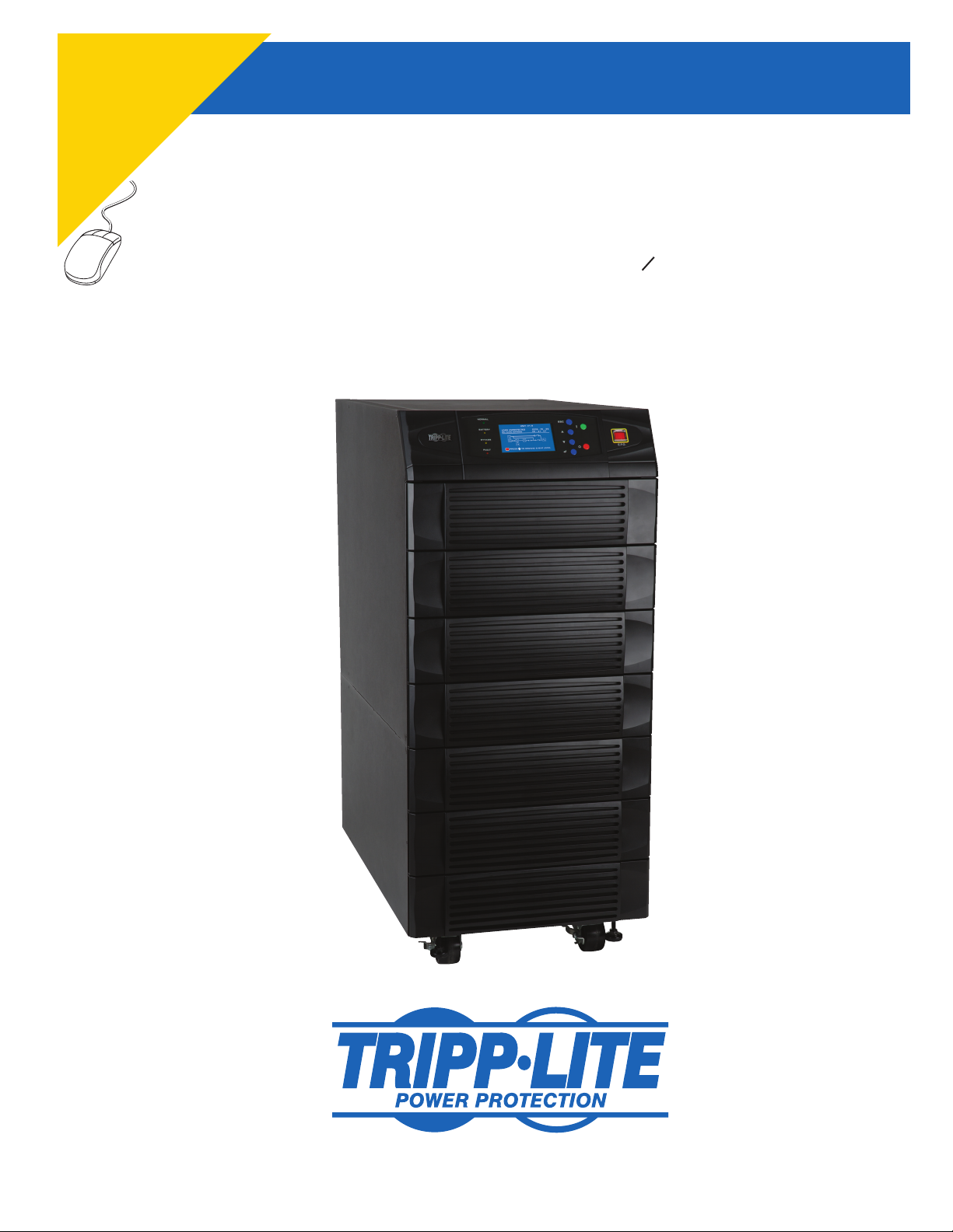
SmartOnline™ 3-Phase UPS Systems
Input/Output: 220/380V, 230/400V or 240/415V AC, 3O, 4-wire + ground
Owner’s Manual
Models: SU20KX, SU40KX, SU60KX, SU80KX
Not suitable for mobile applications.
1
2
3
4
5
6
7
8
9
10
11
12
1111 W. 35th Street, Chicago, IL 60609 USA
www.tripplite.com/support
Copyright © 2010 Tripp Lite. All trademarks are the sole property of their respective owners.
1
13
14
Page 2

Table of Contents
1
1 Introduction 3
2 Important Safety Instructions 4
2
3 Control Panel Features 6
4 Front and Rear Panel Features 7
5 Cabinet Installation 9
3
5-1 Preparation 9
5-2 Unpacking 9
5-3 Placement 10
6 Internal Battery Connection 11
4
(Models SU20KX and SU40KX Only)
6-1 Internal Battery Wiring Diagrams 11
6-2 Internal Battery Connection Procedure 13
7 Wiring 16
5
7-1 Wiring Warnings 16
7-2 Wiring Preparation 16
7-3 UPS System Terminal Block Diagram 17
7-4 External Battery Cabinet Wiring Diagrams 17
6
7-5 Electrical and Cable Data 18
7-6 External Battery Cabinet Wiring 19
7-7 AC Input/Output Wiring (Single UPS) 20
7-8 AC Input/Output Wiring (Parallel UPS – Single Input) 21
7
7-9 AC Input/Output Wiring (Parallel UPS – Dual Inputs) 21
8 Operating Modes 22
8-1 Online (Normal) Mode (Single UPS) 22
8
8-2 Battery Backup Mode (Single UPS) 22
8-3 Auto Bypass Mode (Single UPS) 22
8-4 Manual Bypass Mode (Single UPS) 22
8-5 Online Mode (Parallel UPS) 23
9
8-6 Battery Backup Mode (Parallel UPS) 23
8-7 Auto Bypass Mode (Parallel UPS) 23
8-8 Manual Bypass Mode (Parallel UPS) 24
8-9 Hot Standby Mode (Parallel UPS) 24
10
9 Start-Up, Shutdown and Bypass 25
9-1 Control Panel and Breaker Diagrams 25
9-2 Preliminary Checklist (Single UPS) 25
9-3 Normal Start-Up Procedure (Single UPS) 25
11
9-4 Battery Start-Up Procedure (Single UPS) 26
9-5 Manual Bypass Procedure (Single UPS) 27
9-6 Shutdown Procedure (Single UPS) 27
9-7 Preliminary Checklist (Parallel UPS) 28
12
9-8 Start-Up Procedure (Parallel UPS) 29
9-9 Shutdown Procedure (Parallel UPS) 30
9-10 Manual Bypass Procedure (Parallel UPS) 31
9-11 Switching from Manual Bypass to Normal (Parallel UPS) 32
13
10 Display and Configuration 33
10-1 Control Panel Diagram 33
10-2 Display Hierarchy 33
10-3 Default Display 34
10-3-1 Status Display 34
10-4 Main Menu 37
10-5 UPS Setup 39
10-5-1 Bypass Setup 40
10-5-2 Output Setup 41
10-5-3 Battery Setup 43
10-5-4 Charger Setup 46
10-5-5 Parallel Setup 47
10-5-6 Control & Test Setup 48
10-5-7 Local Setup 50
10-6 Maintenance 53
11 Communications 55
11-1 Communications Interfaces 55
11-2 SNMPWEBCARD Slot 55
11-3 Input Dry Contact Interface 55
11-4 Remote Emergency Power Off (EPO) Circuit Diagram 56
11-5 Auxiliary Dry Contact Input Circuit Diagram 56
11-6 External Battery Cabinet Temperature Inputs 56
11-7 External Battery Status Input 56
11-8 Output Dry Contact Interface Detail 57
11-9 Output Dry Contact Circuit Diagram 58
11-10 RS-232 Serial Port Circuit Diagram 58
11-11 Parallel Configuration Port 58
12 Specifications 59
12-1 UPS System Technical Specifications 59
12-2 UPS System Floor Loading Table 59
12-3 Battery Pack Floor Loading Table 59
13 Storage and Service 60
14 Warranty 60
14
2
Page 3
1 – Introduction
Tripp Lite’s SmartOnline 3-Phase UPS Systems (Models SU20KX, SU40KX, SU60KX and SU80KX) are ideal for backing up and protecting data
centers, telecommunications (VoIP), networks, industrial facilities, security/emergency systems and more.
1
Advanced Features:
True on-line double conversion with superior IGBT inverter technology•
Low input current THD allows 1:1 generator sizing for maximum efficiency and cost savings•
Internal N+1 power module redundancy (SU40KX, SU60KX and SU80KX)•
Built-in parallel or hot standby redundancy (1+1) capability for increased capacity or fault-tolerance•
Up to 80kVA capacity in a compact footprint; up to 160kVA in parallel configuration•
High input power factor and high efficiency with low thermal loss and low noise•
Simplified, easy-to-repair, long-life, high-availability system design•
Redundant auxiliary power and control circuits•
Dual input design with separated rectifier and bypass input•
All models support external battery cabinets for extended battery backup runtime•
High-resolution LCD status screen simplifies operation and delivers detailed operational information, including system block diagrams•
2
3
4
5
6
7
8
9
10
11
12
13
14
3
Page 4

2 – Important Safety Instructions
1
SAVE THESE INSTRUCTIONS
All sections of this manual contains instructions and warnings that should be followed during the installation and operation of the UPS
2
systems described in this manual. Read all instructions thoroughly before attempting to move, install or operate the UPS systems described in
this manual. Failure to comply may invalidate the warranty and cause property damage and/or personal injury.
Location Warnings
3
Install the UPS system in a controlled indoor environment, away from moisture, temperature extremes, flammable liquids and gasses, conductive •
contaminants, dust and direct sunlight.
Install the UPS system in a • level, structurally sound location.
4
The UPS system is extremely heavy; be extremely careful when moving or lifting the unit.•
Operate the UPS system at indoor temperatures between 32° F and 104° F (0° C and 40° C) only. For best results, maintain indoor temperatures •
between 62° F and 84° F (17° C and 29° C).
Leave adequate space around all sides of the UPS system for proper ventilation. Do not block, cover or insert objects into the external ventilation •
5
openings of the cabinet.
Do not place any object on the unit, especially containers of liquid.•
Do not mount the unit with its front or rear panel facing down (at any angle). Mounting in this manner will seriously inhibit the unit’s internal •
cooling, eventually causing product damage not covered under warranty.
6
Do not install the UPS system near magnetic storage media, as this may result in data corruption. Keep all recorded magnetic media a minimum •
of 60 cm (24 inches) away from the UPS system.
Do not attempt to stack the UPS system. Attempting to stack the UPS system may cause permanent damage and create a potential for serious •
personal injury.
7
The casters are designed for minor position adjustments within the final installation area only. The casters are not designed for moving the UPS •
system over longer distances.
The casters are not designed to provide long-term support for the UPS system after final installation. Use the levelers to provide long-term •
support.
8
When moving the UPS system, push from the front or rear, not from the sides.•
Do not attempt to unpack or move the UPS system without assistance.•
Connection Warnings
9
The power supply for the UPS system must be 3-phase rated in accordance with the equipment nameplate. It also must be suitably •
grounded and wired according to all applicable national and local electrical wiring standards, codes and regulations.
The UPS system contains hazardous high voltages that have the potential to cause personal injury or death from electric shock.•
10
11
12
The UPS system has its own energy source (battery – internal and/or external). The output terminals may be live even when the UPS system is •
not connected to an AC supply.
If the UPS system receives power from a motor-powered AC generator, the generator must provide clean, filtered, computer-grade output.•
Use of this equipment in life support applications where failure of this equipment can reasonably be expected to cause the failure of the life •
support equipment or to significantly affect its safety or effectiveness is not recommended. Do not use this equipment in the presence of a
flammable anesthetic mixture with air, oxygen or nitrous oxide.
The UPS system is designed to power modern computer loads and associated peripheral devices. Do not use the UPS system to power pure •
inductive or capacitive loads.
Input and output wiring should be performed by trained, qualified electricians only.•
Due to high leakage current, a proper earth ground connection is essential before connecting the AC supply.•
Isolate the UPS system before working on the circuit. An easily accessible disconnect device should be incorporated in the fixed wiring. The •
disconnect device must disconnect all line conductors simultaneously when opened.
13
14
4
Page 5

2 – Important Safety Instructions
Battery Warnings
The UPS system does not require routine maintenance. There are no user-serviceable parts inside. Only qualified service personnel should open •
the access panels for any reason.
Batteries present a risk of electrical shock and burns from high short-circuit current. Battery connection or replacement should be performed •
only by qualified service personnel, observing proper precautions. Turn off the UPS system before connecting or disconnecting internal
batteries. Use tools with insulated handles. Do not open the batteries. Do not short or bridge the battery terminals with any object.
Replace batteries with equivalent batteries available from Tripp Lite. Do not operate the UPS system without batteries.•
The batteries are recyclable. Refer to local codes for disposal requirements.•
Do not dispose of the batteries in a fire, mutilate the batteries or open the battery coverings.•
Battery fuses should be replaced by qualified service personnel only. Blown fuses must be replaced with the same number and type of fuses. •
Potentially lethal voltages exist within the UPS system as long as the battery supply is connected. Service and repair should be performed •
by trained personnel only, while the UPS system is turned off or placed into bypass mode. Disconnect internal batteries (if present) before
performing any service work by switching off the internal battery circuit breaker and removing the battery fuse(s). Disconnect external batteries
(if present) by switching off the external battery cabinet breaker and disconnecting the external battery cabling from the UPS system.
Do not connect or disconnect batteries when the UPS system is operating from the battery supply or when the unit is not in bypass mode.•
Do not remove the plastic sleeves covering internal batteries.•
Internal and external batteries must be replaced by equivalent batteries available from Tripp Lite.•
Before connecting an external battery cabinet to the UPS system, read the external battery cabinet’s documentation. Use only external battery •
cabinets that have been approved by Tripp Lite.
If the UPS system remains off for an extended period of time, it should be turned on periodically to allow the batteries to recharge. The UPS •
system should be turned on and the batteries should be recharged at least one uninterrupted 24-hour period every 3 months. Failure to recharge
the batteries periodically may cause irreversible battery damage.
Wiring Warnings
See • Section 7-1 for wiring warnings
1
2
3
4
5
6
7
8
9
10
11
12
13
14
5
Page 6
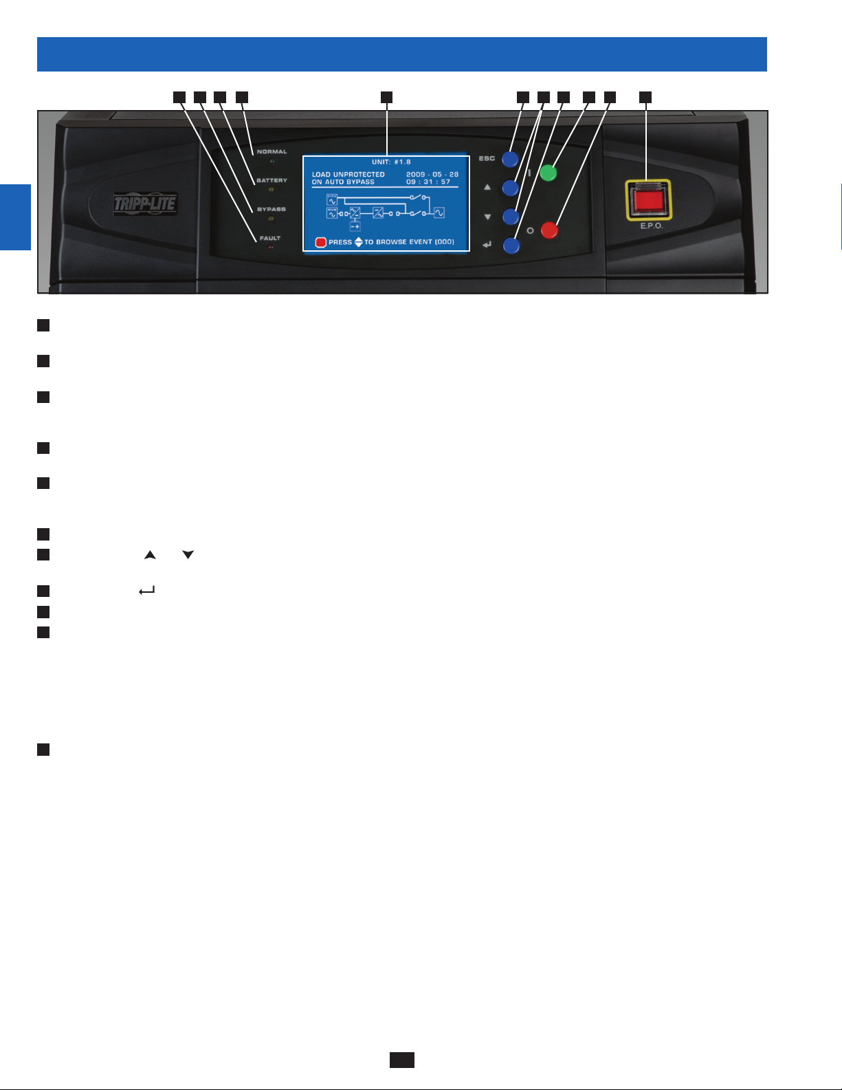
3 – Control Panel Features
1
2
3
4
“NORMAL” LED:• This green light illuminates to indicate that the UPS system is in online (normal) mode. The primary AC input supply is
A
present and within standard operating parameters.
“BATTERY” LED:• This amber light illuminates when the UPS system is in battery backup mode, discharging the batteries to provide power
B
5
6
7
8
9
10
11
12
13
to connected equipment. An audible alarm will also sound.
“BYPASS” LED:• This amber light illuminates when the UPS system is in bypass mode (auto bypass or manual bypass). Battery backup
C
power will not be available to connected equipment while the UPS system is in bypass mode, but connected equipment loads will be
supported by the bypass (reserve) power source.
“FAULT” LED:• This red light illuminates when any UPS system or input power fault occurs. Available diagnostic information will be
D
displayed on the LCD screen.
LCD Status Screen:• This illuminated LCD status screen displays text and graphics to indicate a wide range of UPS system operating
E
conditions and diagnostic data. Note: The LCD backlight will turn off after 10 minutes of inactivity. Turn on the backlight by momentarily
pressing the ON button or one of the scroll buttons.
“ESC” (Escape) Button:• Press this button to return to the previous page or menu.
F
G
Scroll Buttons (• and ): Press these buttons to move the cursor up or down and navigate the control panel menus and screens. These
buttons are also used for data entry in several screens.
Enter Button (• ): Press this button to select a menu item or confirm a setting change.
H
ON Button:• Press and hold this button for 3 seconds to turn the UPS system’s inverter ON.
I
J
OFF Button:• Press and hold this button for 3 seconds to turn the UPS system’s inverter OFF. If the UPS system is in online (normal) mode, it
will switch to auto bypass mode.
Note: Switching the inverter OFF does not stop the converter stage of the UPS and therefore, the connected battery is still charging as
required.
Note: After switching the inverter OFF, if the battery circuit breaker or AC main input circuit breaker are opened and remain open for an
extended period of time, the batteries should be recharged periodically. At a minimum, the batteries should be charged for an uninterrupted
24-hour period every 3 months to maintain their longest usable life. Failure to recharge the batteries may cause irreversible battery damage.
“EPO” (Emergency Power Off) Button:• Press this button to turn the UPS system’s output OFF and also disable bypass output.
K
If the UPS system is in battery backup mode when the EPO button is activated:
Main output and bypass output are turned off, the alarm sounds, fans shut down after approximately one minute, and control circuitry •
remains active.
Releasing the EPO button (by pressing it again) turns off the UPS system completely, including the alarm and control circuit. Press the •
ON button for 3 seconds to restart the UPS system.
If the UPS system is in online (normal) mode when the EPO button is activated:
Main output and bypass output are turned off, the alarm sounds, fans and control circuitry remain active.•
Releasing the EPO button (by pressing it again) turns off the alarm and places the UPS system in auto bypass mode. Press the ON button •
for 3 seconds to return the UPS system to online (normal) mode.
See Section 10 – Display and Configuration for detailed information about the control panel’s menus and displays.
A E F G H I J KBCD
14
6
Page 7
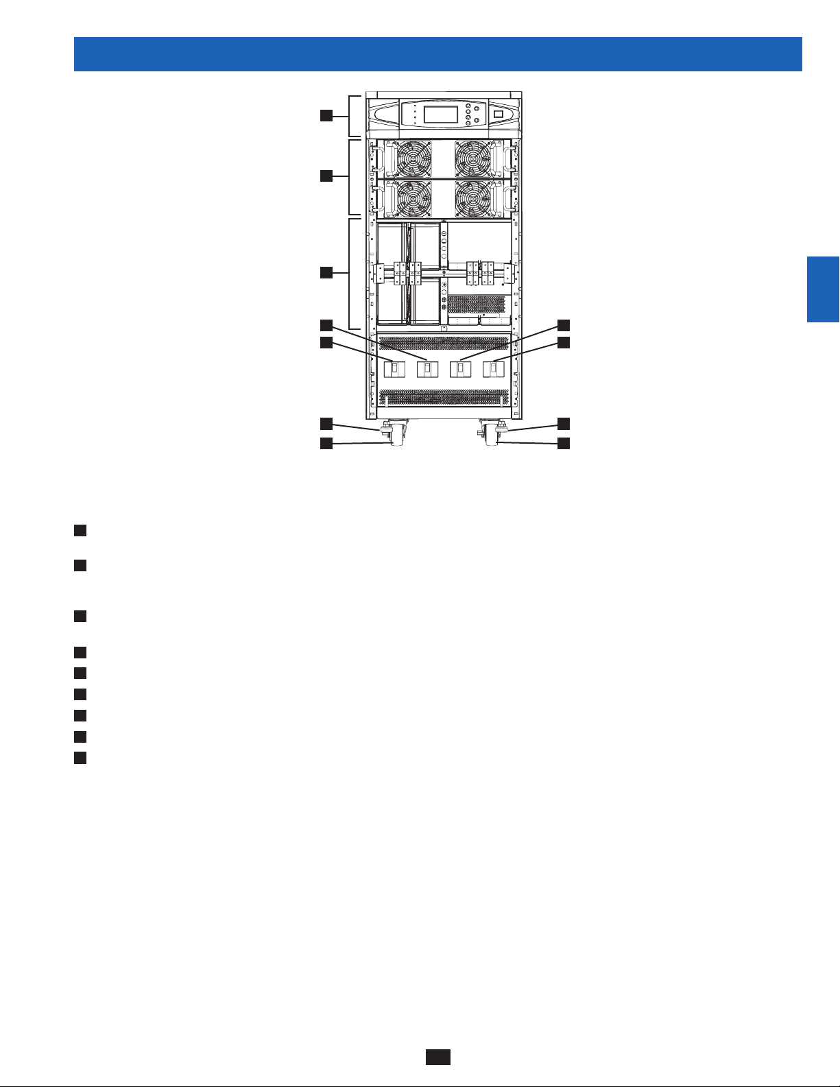
4 – Front and Rear Panel Features
A
B
C
E F
D
1
2
3
4
G
5
H H
I I
SU40KX shown (front)
Note: Individual models may vary from diagrams. Unit shown with front bezels removed.
Control Panel:• The control panel allows the operator to monitor and control the UPS system. See Section 3 – Control Panel Features for
A
more information.
B
Internal Power Modules:• 20kVA internal power modules can be replaced in the field without powering down connected equipment loads.
The number of internal power modules varies by model. The internal power modules are capable of N+1 redundancy in SU40KX, SU60KX
and SU80KX models.
C
Internal Battery Pack Compartment (SU20KX and SU40KX only;):• Internal batteries must be connected by a qualified electrician. See
Section 6 – Internal Battery Connection for more information.
D
Output Circuit Breaker Switch (Q4):• Controls AC output power.
E
Manual Bypass Circuit Breaker Switch (Q3):• Controls AC input power to the UPS system during manual bypass operation.
F
Bypass Input Circuit Breaker Switch (Q2):• Controls AC input power to the UPS system during auto bypass operation.
G
Main Input Circuit Breaker Switch (Q1):• Controls AC input power to the UPS system during online (normal) operation.
Levelers:• The levelers provide long-term support for the UPS system.
H
Casters:• The casters are designed for small position adjustments within the final installation location only; they are not designed for moving
I
the UPS system over longer distances. The casters are not designed to provide long-term support for the UPS system after final installation.
Use the levelers to provide long-term support.
6
7
8
9
10
11
12
13
14
7
Page 8
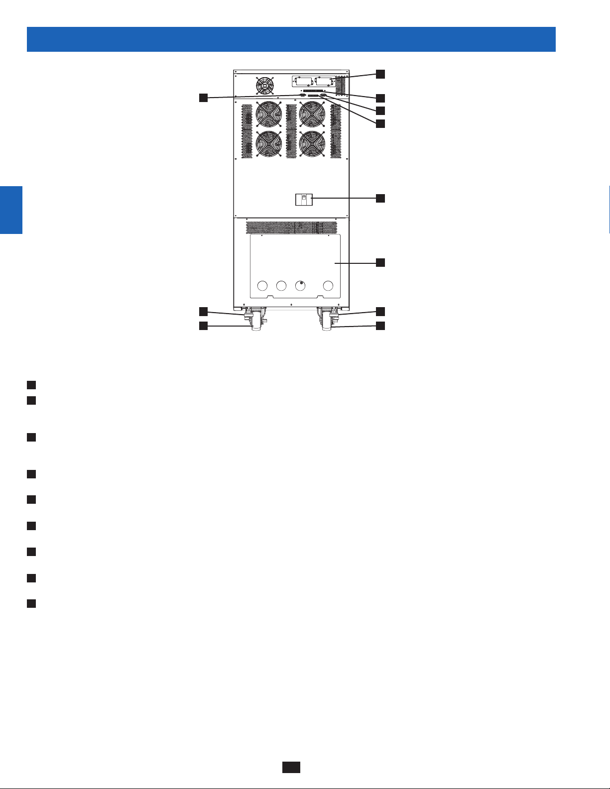
4 – Front and Rear Panel Features (continued)
1
J
2
L
3
4
5
6
7
Note: Individual models may vary from diagrams. Unit shown with front bezels removed.
H
Levelers:• The levelers provide long-term support for the UPS system.
I
Casters:• The casters are designed for small position adjustments within the final installation location only; they are not designed for moving
the UPS system over longer distances. The casters are not designed to provide long-term support for the UPS system after final installation.
8
9
10
11
12
Use the levelers to provide long-term support.
J
Accessory Slot:• Remove the cover panel to install a Tripp Lite SNMPWEBCARD accessory. The SNMPWEBCARD accessory provides an
Ethernet interface for the UPS system and enables remote monitoring and control via SNMP, Web browser or telnet. Visit www.tripplite.com
for more information about the SNMPWEBCARD accessory.
K
RS-232 Serial Communications Port:• This DB9 port connects the UPS system to compatible workstations or servers, enabling automatic
shutdown during extended blackouts and monitoring of operating and power conditions.
L
Parallel Configuration Port:• This DB9 port connects the UPS system to another UPS system of identical type and capacity for use in a
parallel redundancy (1+1) configuration. See Section 7 – Wiring and Section 8 – Operating Modes for more information.
M
Input Dry Contact Interface:• This interface receives dry contact signals that allow the UPS system to receive commands and monitor
external battery conditions. See Section 11 - Communications for more information.
N
Output Dry Contact Interface:• This interface allows the UPS system to send information via dry contact communications. See Section 11 –
Communications for more information.
O
Internal Battery Circuit Breaker Switch (SU20KX and SU40KX only):• Controls the input/output power of the UPS system’s internal
batteries.
P
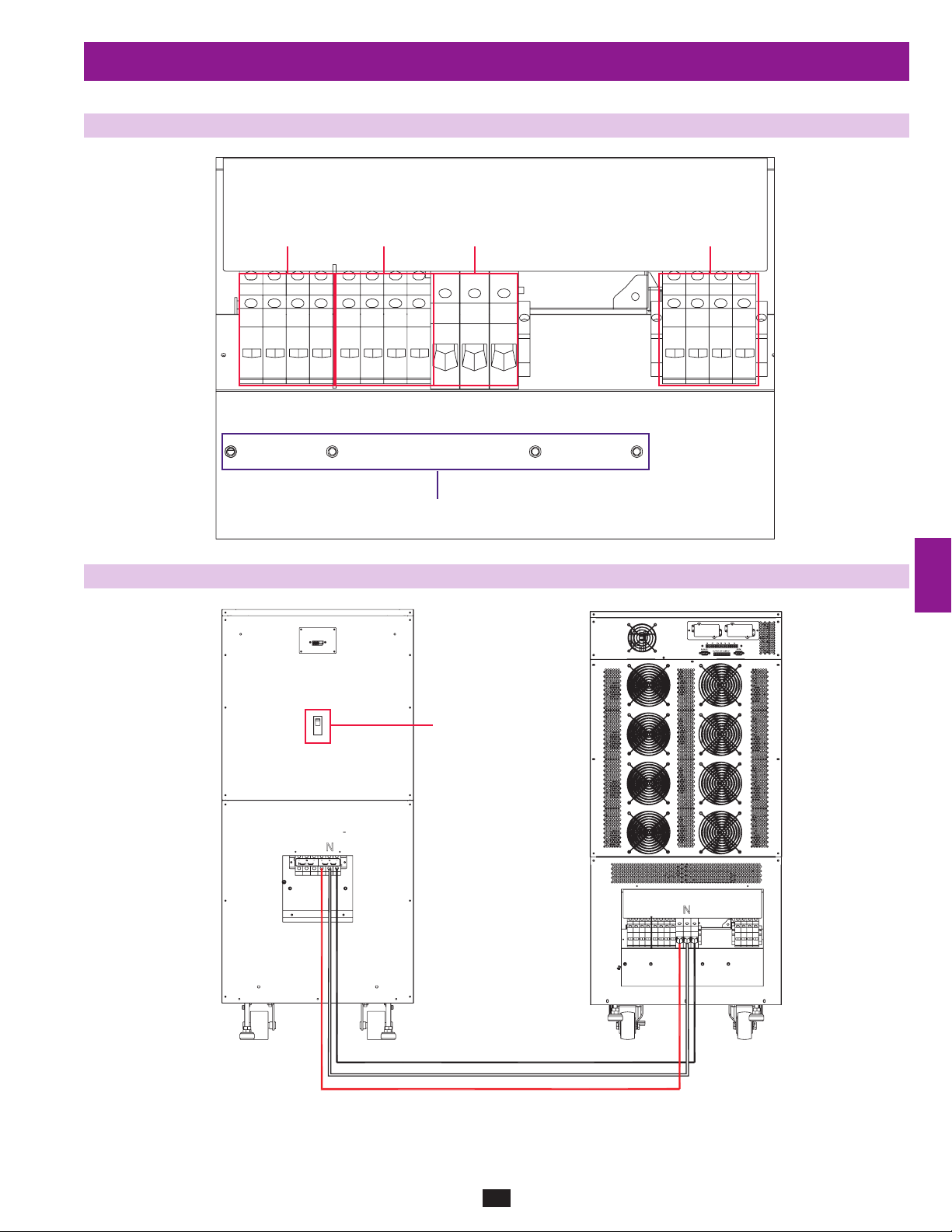
Terminal Block Cover:• Remove the terminal block cover to access the UPS system’s input, bypass input, external battery cabinet, output and
grounding connection terminals. Wiring conduits pass through the circular knockouts in the terminal block cover. See Section 7 – Wiring for
more information, including a detailed diagram of the terminal block.
H
I I
SU40KX shown (rear)
M
K
N
O
P
H
13
14
8
Page 9
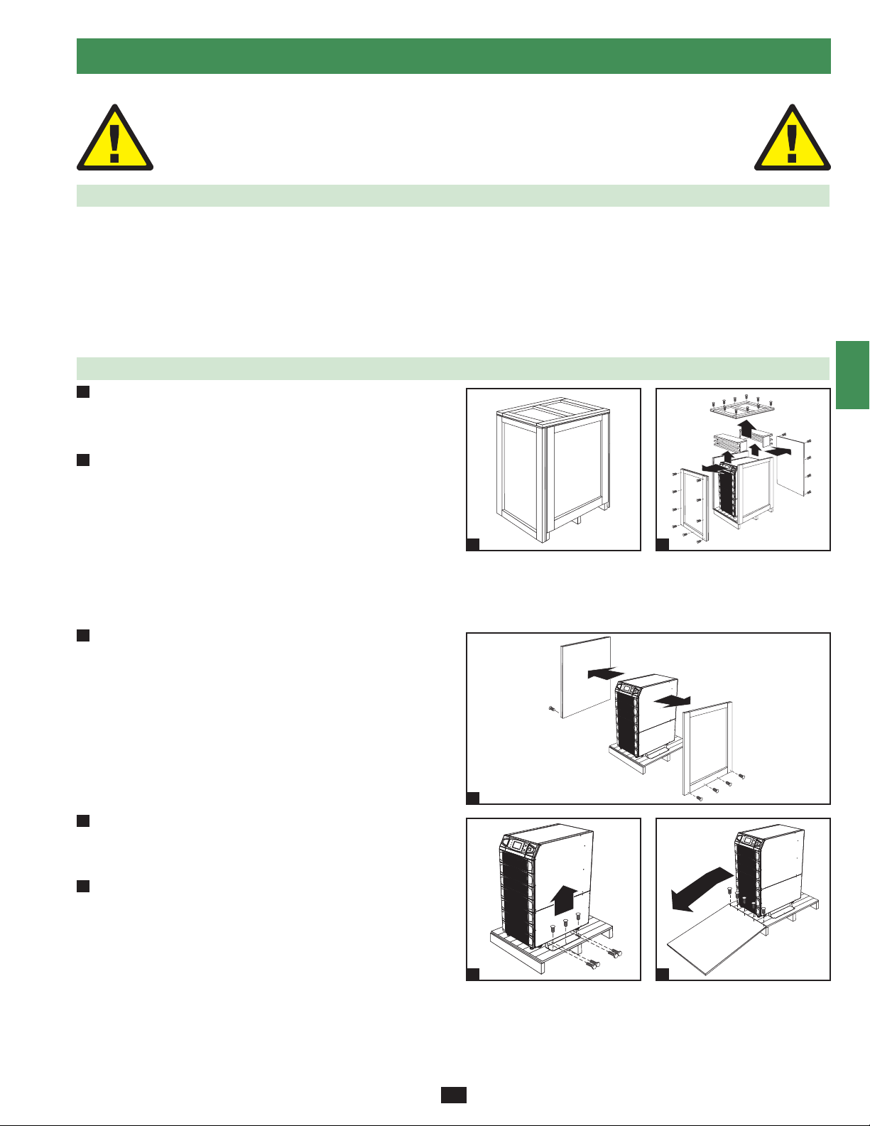
5 – Cabinet Installation
1
Read Section 2 – Important Safety Instructions Before Installation
5-1 Preparation
The UPS system must be installed in a structurally sound area with a level floor that is able to bear the weight of the UPS system, any external
battery cabinet and other equipment that will be installed nearby. The installation site should also have a dedicated AC circuit available that is
compatible with the UPS system’s input requirements. (See Section 12 – Specifications for details on input requirements and floor loading
requirements.) Before unpacking the unit, you should transport the shipping container closer to the final installation site to minimize the distance
you will need to move the unit after the protective shipping container has been removed. If you plan to store the UPS system for an extended
period before installation, follow the instructions in Section 13 – Storage and Service. (Unpacking and storage instructions are also printed on the
“Unpacking and Storage Instructions” sheet secured to the shipping container.) Warning: Do not attempt to unpack or move the UPS system
without assistance.
5-2 Unpacking
1
Inspect the shipping container(s) for visible damage. If you •
determine that the unit has been damaged during shipping, contact
Tripp Lite for assistance. Do not attempt to use the UPS system if
it has been damaged or mishandled.
2
Confirm that the shipping container is upright and use a •
screwdriver to remove its top panel, front panel and back panel.
Also remove the plastic wrap and interior cushioning material.
Confirm that the model name and rating at the rear of the cabinet
match the unit you ordered. Examine the cabinet for any damaged
or loosened parts. Confirm that the shipping container includes the
accessories that ship with the unit. The UPS system should include
an RS-232 serial cable, a parallel redundancy cable, a remote EPO
wiring connector, a dry contact input connector (4 contacts), a dry
contact output connector (12 contacts) and a software CD-ROM. If
anything is missing or damaged, contact Tripp Lite for assistance.
Confirm that the unit is stable, then remove the side panels from •
3
the shipping container.
1
2
2
3
4
5
6
7
8
Remove the bolts from the shipping brackets securing the unit •
4
to the pallet, then remove the shipping brackets from the UPS
system. Warning: Be extremely careful, as the unit could shift
unexpectedly.
5
Use several of the screws you removed in step 2 to attach the top •
panel of the shipping container to the front edge of the shipping
pallet. The smooth surface of the panel should face upward so
that it can be used as a ramp for rolling the unit off the shipping
pallet. Do not attempt to use the top panel as a ramp if it is cracked
or otherwise structurally damaged. Make sure the casters at the
bottom of the unit are unlocked. Using extreme caution, slowly roll
the unit down the ramp with the aid of several assistants.
9
10
3
11
12
4
5
13
14
9
Page 10
50 cm (19.7”)
50 cm (19.7”)
100 cm (39.4”)
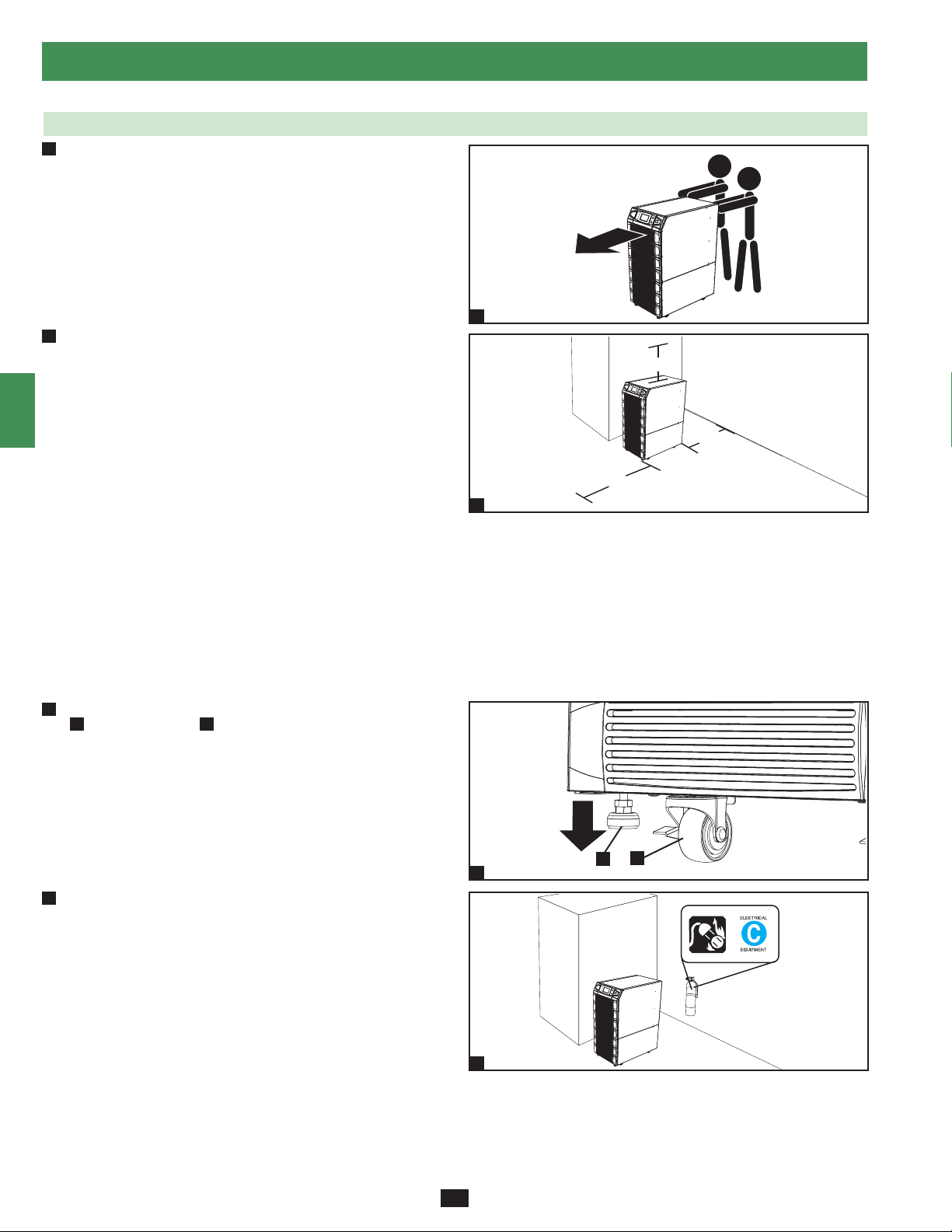
5 – Cabinet Installation (continued)
1
5-3 Placement
Use the casters to move the UPS system for a short distance over •
1
2
3
4
5
6
7
8
9
a level, smooth, stable surface. Do not attempt to use the casters
to move the UPS system over longer distances. The UPS system
should be moved close to its final installation location inside
its shipping container before it is unpacked from the shipping
container. Use a mechanical device of sufficient capacity to move
the shipping container. Warning: The UPS system could tip if it
is moved over an unstable surface. Be extremely careful when
moving the UPS system. Push the UPS system from the front or
rear, not from the sides.
2
Position the UPS system in a structurally sound area with a •
level floor that is able to bear the weight of the UPS system,
any external battery cabinets and other equipment that will be
installed nearby. The installation site should also have a dedicated
AC circuit available that is compatible with the UPS system’s
input requirements. (See the Section 12 – Specifications for
more information about input requirements and floor loading
requirements.) The UPS system must be installed in a clean,
secure environment with a relative humidity less than 90% (noncondensing). Operate the UPS system at indoor temperatures
between 17° C and 29° C (62° F and 84° F). Prevent damage to
cabling by using suitable protective conduits. In order to maintain
proper airflow and service access, you must maintain the following
clearances:
At least 100 cm (39.4”) clearance in front of the UPS system.•
At least 50 cm (19.7”) clearance behind the UPS system.•
At least 50 cm• (19.7”) clearance above the UPS system.
Warning: The cooling fans circulate air from front to back. Do not
use any air conditioning or fan that blows air directly toward the
rear of the UPS system.
After moving the UPS system to its final location, lock the casters •
3
A
and use the levelers B to stabilize the cabinet. Ensure that all
four levelers make firm contact with the floor.
1
2
10
11
12
13
14
For emergency use, install a fire extinguisher rated for energized •
4
electrical equipment fires (Class C rating or exact equivalent, with
a non-conductive extinguishing agent) near the UPS system.
10
A
3
4
B
Page 11
VBoard
W1: RED, W2: BLUE, W3: WHITE, W4: BLACK
12V, 9AH, 10PCS
12V, 9AH, 10PCS
12V, 9AH, 10PCS
12V, 9AH, 10PCS
RED RED
RED RED
BLACK BLACK
BLACK BLACK
RED RED
RED RED
BLACK BLACK
BLACK BLACK
B+
W1
W1
W1
W1
W2
W2
W2
W2
12V, 9AH, 10PCS
12V, 9AH, 10PCS
12V, 9AH, 10PCS
12V, 9AH, 10PCS
W4
W4
W4
W4
W3
W3
W3
W3
B-
N
VBoard
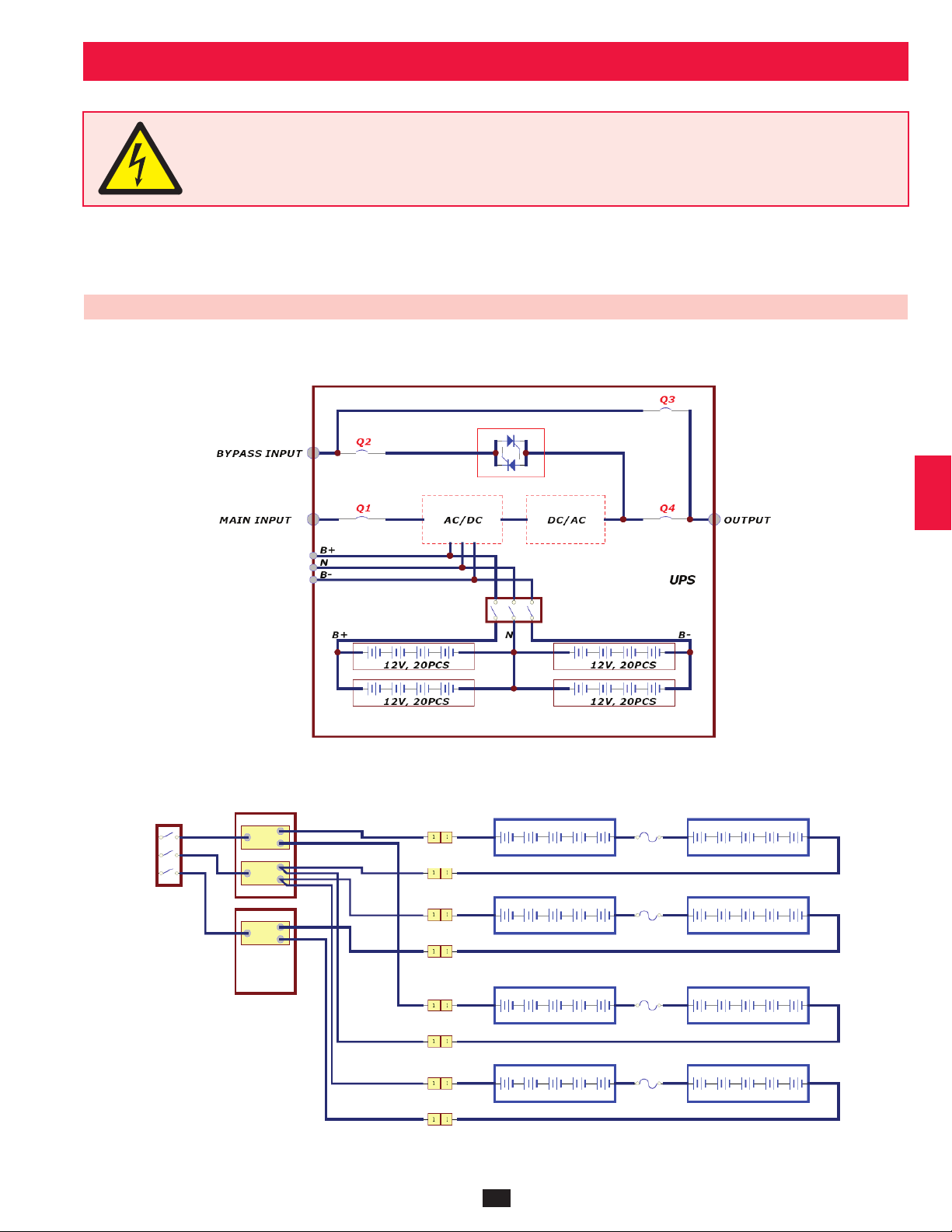
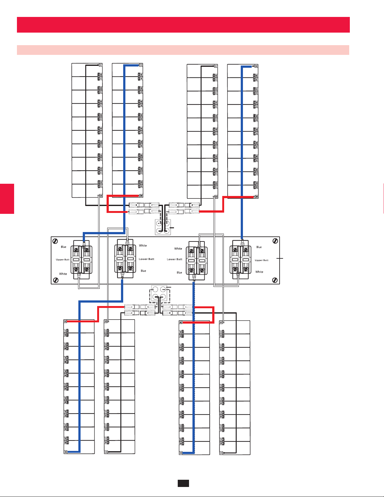
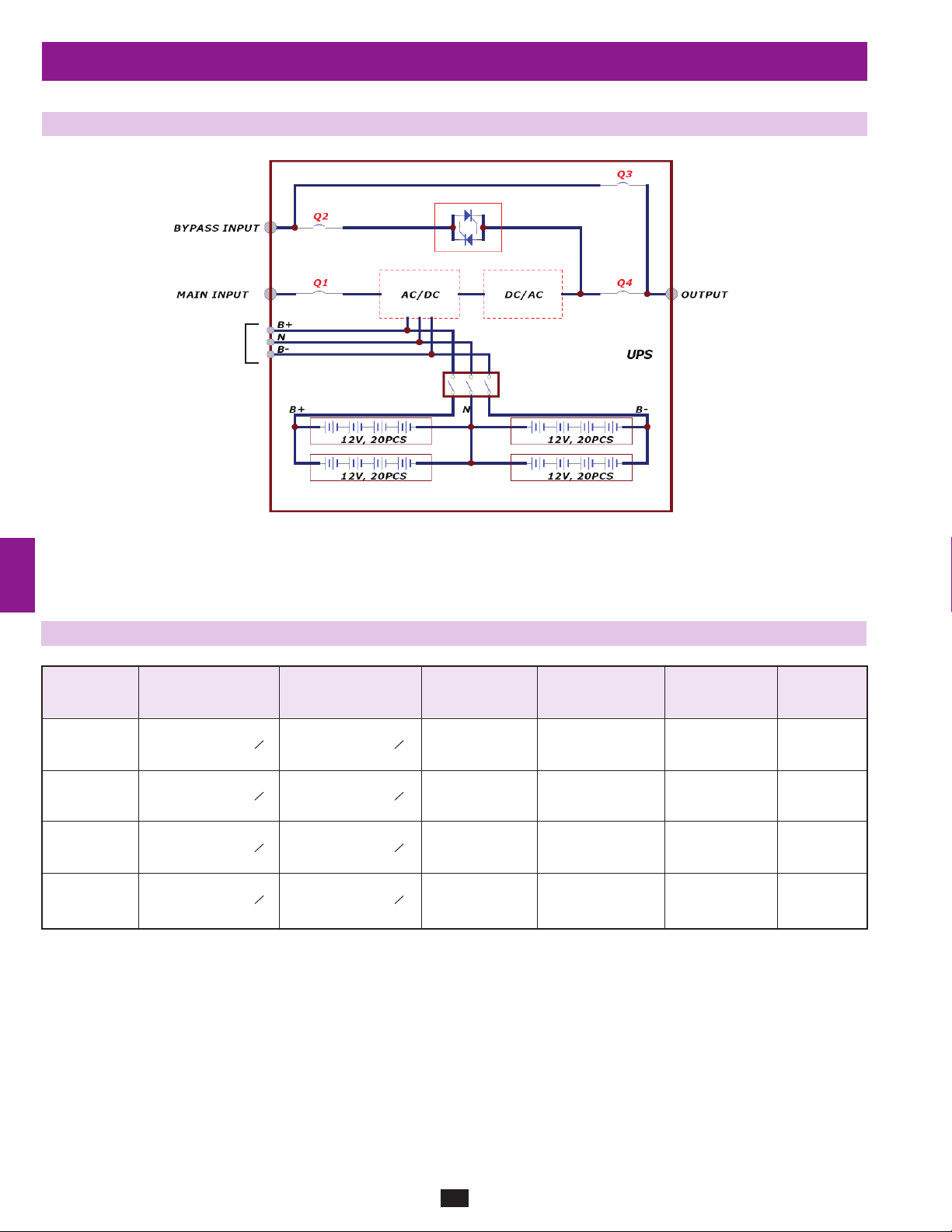
6 – Internal Battery Connection (Models SU20KX and SU40KX Only)
DANGER! LETHAL HIGH VOLTAGE HAZARD!
Potentially lethal high voltage exists within the batteries, even when not connected to a UPS system. Battery connection
should be performed by qualified service personnel only, following all the precautions listed in this manual and adhering to
local electrical codes. Read Section 2 – Important Safety Instructions before proceeding.
1
2
Internal battery connection is for models SU20KX and SU40KX only. Each internal battery pack consists of two strings of batteries: one string
with a black cable and one string with a red cable. The number of internal battery packs varies with model.
6-1 Internal Battery Wiring Diagrams
Review the internal battery wiring diagrams prior to connecting the internal batteries. The UPS system can accept up to four internal battery packs
(each pack consists of two strings; each string consists of 10 batteries). The number of internal battery packs varies with model.
3
4
5
6
7
8
SU40KX shown
10
9
SU40KX shown
11
11
12
13
14
Page 12
UPS System
Battery Back
Connector
UPS System
Battery Back
Connector
Fuse Block Bracket
6 – Internal Battery Connection (continued)
1
6-1 Internal Battery Wiring Diagrams (continued)
2
3
4
5
6
10
11
12
7
8
9
13
14
SU40KX shown
12
Page 13
6 – Internal Battery Connection (continued)
6-2 Internal Battery Connection Procedure
Place the UPS system in bypass (or turn it completely off) and turn •
1
off the internal battery circuit breaker switch, located on the rear of
the UPS system.
1
2
3
Remove the battery access bezels, located on the front of the UPS •
2
system.
3
Remove the battery cartridge fuses from each fuse block.•
Disconnect the blue and white jumper cables attached to each fuse •
4
block. Warning: When disconnecting the jumper cables, pull
them straight away from the fuse block with even force. Do not
wiggle them side-to-side, as this may damage the connector.
1
4
5
6
2
7
8
3
9
5
10
11
4
Remove the fuse block bracket. Note its orientation before •
removal.
12
13
5
14
13
Page 14
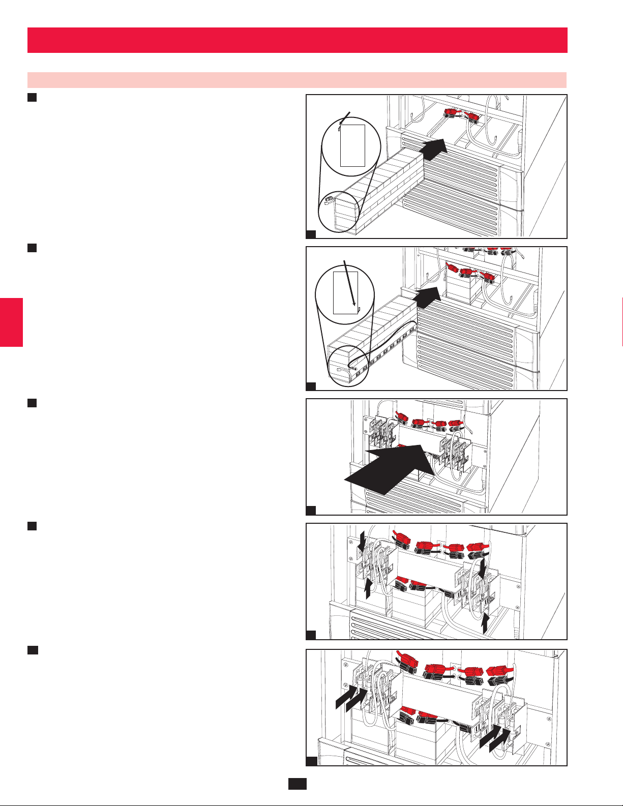
6 – Internal Battery Connection (continued)
1
6-2 Internal Battery Connection Procedure (continued)
Slide a battery string with a red cable into an empty slot within •
6
2
the battery compartment. Make sure the battery string is oriented
as shown in the diagram. Note: Start with the empty slots at the
bottom of the battery compartment and work toward the empty
slots at the top of the battery compartment.
TERMINALS
3
SIDE VIEW
4
6
7
Slide a battery string with a black cable into an empty slot within •
the battery compartment, next to the battery string that you inserted
5
in step 6. Make sure the battery string is oriented as shown in the
diagram. Repeat steps 6 and 7 as needed until all the battery strings
have been inserted into the empty battery slots. Note: Depending
on the model of the UPS system, some battery compartment slots
may remain empty.
TERMINALS
SIDE VIEW
6
7
7
Reconnect the fuse block bracket. (The letters on the fuse block •
8
bracket should be upright when it is in the correct orientation.)
8
10
11
12
13
14
9
8
Connect the blue and white jumper cables on each internal battery •
9
pack to the corresponding fuse block. The labeling next to the fuse
block identifies the correct fuse block for each cable.
9
10
Insert the battery cartridge fuses into each fuse block. The fuses are •
interchangeable. Make sure the fuses are firmly snapped into place.
Warning: Battery cartridge fuses must be inserted last due to
potential arcing of connectors. Blown fuses must be replaced
by a qualified electrician. Replace only with fuses of the same
type and rating.
10
14
Page 15
240
6 – Internal Battery Connection (continued)
6-2 Internal Battery Connection Procedure (continued)
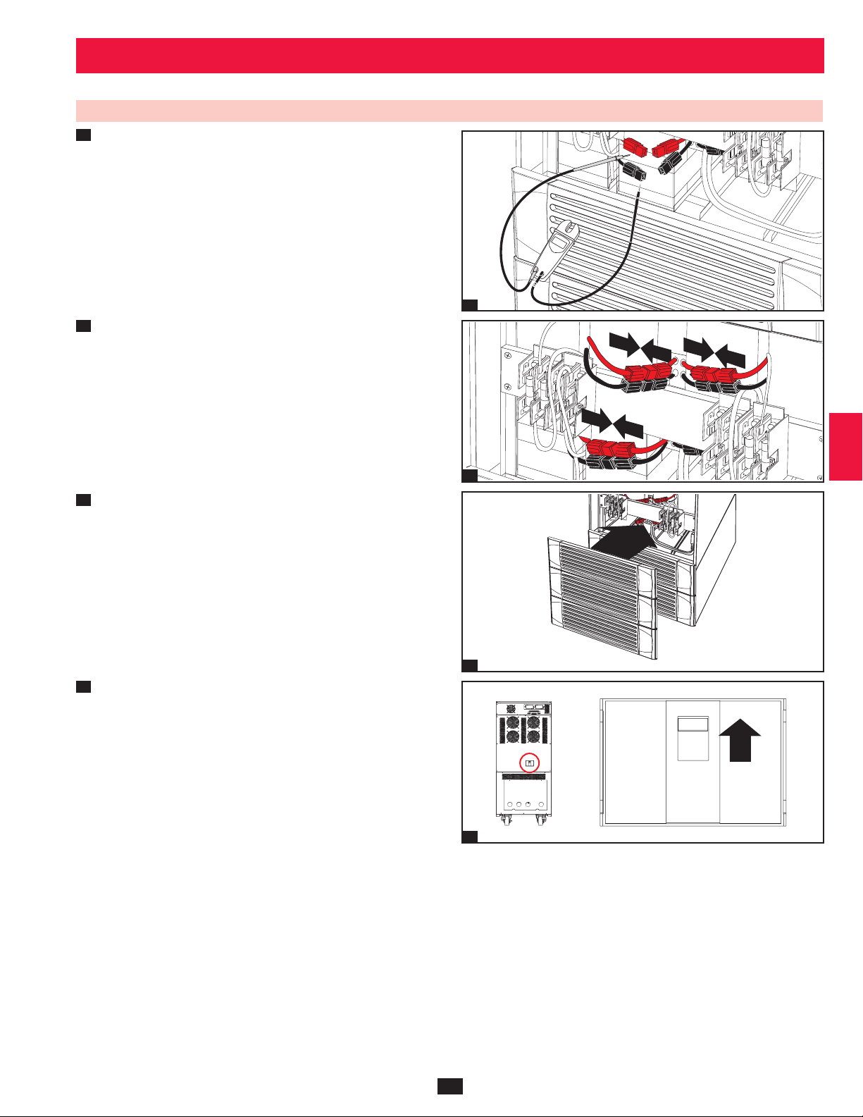
11
Use a voltmeter (user-supplied) to test the voltage of each internal •
battery pack. Observing proper polarity, connect the voltmeter’s
black probe to the battery pack’s black connector; connect the
voltmeter’s red probe to the battery pack’s red connector. Make
sure the voltmeter’s probes touch the metal contacts inside the
battery pack’s connectors. The battery pack’s acceptable DC
voltage range is between 220V and 280V DC (nominal 240V DC).
If several voltmeter tests yield results outside the acceptable DC
voltage range, contact Tripp Lite for assistance in determining the
possible causes of the incorrect voltage reading before proceeding.
1
2
3
Connect the • black cable for each internal battery pack to the
12
nearest black connector located inside the UPS system’s battery
compartment. Connect the red cable for each internal battery
pack to the nearest red connector located inside the UPS system’s
battery compartment. Warning: Observe proper polarity by
connecting negative to negative (black to black) and positive
to positive (red to red). Failure to observe proper polarity will
damage the UPS system and create a serious risk of personal
injury and property damage.
13
Replace the battery access bezels.•
14
Follow the proper procedure to restart the UPS and re-transfer the •
critical load to protected power.
Note: If you need to remove or replace internal battery packs, modify
steps 6 and 7 by removing and/or replacing the existing internal battery
packs, as required.
11
12
13
4
5
6
7
8
9
10
14
12
13
11
15
14
Page 16

7 – Wiring
1
DANGER! LETHAL HIGH VOLTAGE HAZARD!
2
7-1 Wiring Warnings
3
De-energize all input and output power sources of the UPS system before installing cables or making electrical connections.•
Use flexible cable of sufficient length to permit UPS system servicing. The maximum cable length is 10 m (32.8 ft).•
Use ferrule caps to cover termination cables and prevent frayed ends from shorting on the UPS system terminal block.•
4
Use cabling rated VW-1, FT-1 or better.•
Use cable sleeves and connector clamps.•
The neutral conductor must be the same size as the current conductors.•
Tighten all connections with a torque of at least 3.95 N·m (35 in·lb)•
5
Confirm that all cables are marked correctly according to their purpose, polarity, phase and diameter.•
If the UPS system’s input/output power source is wye-wye, then “Neutral” and “Ground” must not be connected.•
If the input power source has VNG>0, install a grounded wye secondary isolation transformer with a properly bonded neutral to ground before •
6
the UPS system and input power source.
For equipment requiring a neutral connection to an IT power distribution system that requires neutral isolation upon disconnect, the disconnect •
device must be a four-pole device and must disconnect all line conductors and the neutral conductor. If a disconnect device interrupts the neutral
conductor, it must simultaneously interrupt all line conductors.
7
Allow the batteries to charge uninterrupted for 24 hours after the initial wiring connection.•
Observe proper polarity by connecting negative to negative, positive to positive and normal “N” to normal “N”. Failure to observe proper •
polarity will damage the UPS system and create a serious risk of personal injury and property damage.
Observe proper phase by connecting R to R, S to S, T to T and N to N. Source power phase rotation must be verified as RST before powering •
8
the UPS. Failure to observe proper phase will damage the UPS system and create a risk of personal injury and property damage.
All wiring should be performed by a qualified electrician, in accordance with the warnings in this manual and all applicable
electrical and safety codes. Incorrect wiring may damage the UPS system severely and cause serious personal injury and
property damage. Read Section 2 – Important Safety Instructions before proceeding.
7-2 Wiring Preparation
De-energize all input and output (AC and DC) of the UPS system and external battery cabinet (if present).•
9
Mark all cables according to their correct purpose, polarity, phase and diameter.•
Review the diagrams in • Section 7-3 and Section 7-4 to familiarize yourself with the terminal blocks.
Consult the table in • Section 7-5 to find the correct electrical input/output characteristics for the UPS system.
10
Note: If the UPS system’s input/output power source is wye-wye, then “Neutral” and “Ground” must not be connected. If the input power source
has VNG>0, install an isolation transformer before the UPS system and input power source, then connect the UPS system’s “Neutral” and
“Ground” together.
11
12
13
14
16
Page 17
+ –
+
–
7 – Wiring (continued)
7-3 UPS System Terminal Block Diagram
1
2
Main Input
R
S
R
T
N
S
Grounding Terminals
External Battery
Connection
T
N
7-4 External Battery Cabinet Wiring Diagrams
N+ –
OutputBypass Input
R
S
T
N
3
4
5
6
7
8
External Battery
Cabinet Breaker
Switch
SU80KX and BP480V40C shown for illustration only; consult the battery cabinet’s documentation for exact specifications
9
10
11
12
13
14
17
Page 18
7 – Wiring (continued)
1
7-4 External Battery Cabinet Wiring Diagrams (continued)
2
3
4
TO EXTERNAL
BATTERY CABINET
5
6
External Battery Cabinets
B Cabinet: 26AH, 125A Fuses
C Cabinet: 40AH, 160A Fuses
7
10 Year Cabinet: 55AH, 78AH, 103AH, 140AH; 250A Circuit Breaker
7-5 Electrical and Cable Data
SU40KX shown
8
Input, Bypass Input, Reserve,
and Output Output and Battery Battery Circuit Battery Cable
Model Input Output Breaker Size Cable Size Breaker Fuse Size Size
SU20KX 220/380V, 230/400V 220/380V, 230/400V 125A 50 mm2
9
or 240/415V AC, 3O, or 240/415V AC, 3O, 50A 10 mm2 160A 70 mm2
4-wire + ground 4-wire + ground 250A 70 mm
SU40KX 220/380V, 230/400V 220/380V, 230/400V 125A 50 mm2
or 240/415V AC, 3O, or 240/415V AC, 3O, 75A 25 mm2 160A 70 mm2
4-wire + ground 4-wire + ground 250A 70 mm
10
SU60KX 220/380V, 230/400V 220/380V, 230/400V 125A 50 mm2
or 240/415V AC, 3O, or 240/415V AC, 3O, 125A 50 mm2 160A 70 mm2
4-wire + ground 4-wire + ground 250A 70 mm
SU80KX 220/380V, 230/400V 220/380V, 230/400V 125A 50 mm2
or 240/415V AC, 3O, or 240/415V AC, 3O, 150A 70 mm2 160A 70 mm2
11
4-wire + ground 4-wire + ground 250A 70 mm
2
2
2
2
12
13
14
18
Page 19

+ –
+ –
+
–
7 – Wiring (continued)
7-6 External Battery Cabinet Wiring
Warning: External battery cabinets vary. Read the external battery cabinet’s documentation before attempting to connect it to the UPS
system. Use only external battery cabinets that have been approved by Tripp Lite.
Note: An external battery cabinet is required with models SU60KX and SU80KX. It is optional with models SU20KX and SU40KX. Contact Tripp
Lite for external battery cabinet ordering information.
De-energize all input and output (AC and DC) of the UPS system •
1
and external battery cabinet, and confirm that the external battery
cabinet breaker switch
been wired to an AC power source, see Section 9-6 for shutdown
instructions.)
2
Remove the terminal block covers from the UPS system and •
external battery cabinet.
is off. (If the UPS system has already
A
A
1
1
2
3
4
5
6
3
Connect the positive (+), neutral (N) and negative (-) UPS •
system connection terminals of the external battery cabinet to the
corresponding positive (+), neutral (N) and negative (-) external
battery connection terminals of the UPS system. See Section 7-3
and the external battery cabinet’s documentation for terminal
block diagrams. See Section 7-4 for wiring diagrams. See Section
7-5 for cable size requirements. Cabling should be protected by
flexible conduit and routed through the appropriate knockouts in
the terminal block cover. Warning: Observe proper polarity by
connecting negative to negative and positive to positive. Failure
to observe proper polarity will damage the UPS system and
create a risk of personal injury and property damage.
4
Connect the external battery cabinet’s grounding terminal•
UPS system’s corresponding grounding terminal
(5.189 mm) ground cable. Keep the ground cable connected at all
times after installation.
5
Connect the UPS system’s grounding terminal•
facility’s earth ground
ground cable. Keep the ground cable connected at all times after
installation.
Replace the terminal block cover of the external battery cabinet. If •
6
you do not plan to wire the AC input/output of the UPS system at
this time, replace the terminal block cover of the UPS system.
with a 4 AWG (5.189 mm) minimum
B
with a 4 AWG
B
to your
A
A
to the
2
7
8
9
3
10
A
B
4
11
12
13
B
A
65
19
14
Page 20

+ –
+ –
R S T N R S T N R S T N
7 – Wiring (continued)
1
7-7 AC Input/Output Wiring (Single UPS)
After de-energizing all input and output (AC and DC) of the UPS •
1
2
3
system, remove the terminal block cover from the UPS system.
10
4
If you did not connect the ground cable in • Section 7-6, connect the
2
UPS system’s grounding terminal
B
with a 4 AWG (5.189 mm) ground cable. Keep the ground cable
connected at all times after installation.
to your facility’s earth ground
A
1
5
B
A
6
3
Remove the UPS system’s front bezel to expose the circuit •
breakers. First, confirm that the main input circuit breaker switch
Q1
and the bypass input circuit breaker switch
7
Second, confirm that the manual bypass circuit breaker switch
is off. Third, confirm that the output circuit breaker switch
off.
are both off.
Q2
Q4
Q3
is
2
Q4 Q2 Q1Q3
8
3
4
Confirm the phase of each cable, then connect the cables according •
9
to the UPS system terminal block diagram in Section 7-3. See
Section 7-5 for cable size requirements. Cabling should be
protected by flexible conduit and routed through the appropriate
knockouts in the terminal block cover. Warning: Observe proper
phase rotation by connecting R to R, S to S, T to T and N to N.
Failure to observe proper phase will damage the UPS system
and create a risk of personal injury and property damage.
11
12
13
14
4
5
Replace the UPS system’s terminal block cover.•
5
20
Page 21

7 – Wiring (continued)
7-8 AC Input/Output Wiring (Parallel UPS – Single Input Source)
Parallel UPS Warnings:
The total input cable length must be equal to the total •
output cable length in order to prevent unbalanced load
sharing between two UPS systems under reserve mode
(i.e. Res1 + OP1 = Res2 + OP2; deviation must be <10%).
Parallel configuration only supports 2 UPS systems (1+1 •
redundancy or capacity). Do not attempt to link more than
two UPS systems via parallel configuration.
The UPS systems must have the same rating and capacity •
for parallel UPS installation. Attempting to link
dissimilar UPS systems will damage the UPS systems
and create a serious risk of personal injury and property
damage.
Each UPS must have its Parallel group set to 2 and a •
different “Parallel ID” that indicates the UPS systems are
being run in parallel. (See Section 10-5-5 for more details.)
1
Follow the steps in • Section 7-7, wiring the UPS systems as shown
in the diagram.
2
Connect the included parallel UPS cable•
of each UPS system.
to the parallel port
A
B
1
1
2
3
4
5
B
6
2
7-9 AC Input/Output Wiring (Parallel UPS – Dual Input Sources)
Parallel UPS Warnings:
The total input cable length must be equal to the total •
output cable length in order to prevent unbalanced load
sharing between two UPS systems under reserve mode
(i.e. Res1 + OP1 = Res2 + OP2; deviation must be <10%).
Parallel configuration only supports 2 UPS systems (1+1 •
redundancy or capacity). Do not attempt to link more than
two UPS systems via parallel configuration.
The UPS systems must have the same rating and capacity •
for parallel UPS installation. Attempting to
link dissimilar UPS systems will damage the UPS systems
and create a serious risk of personal injury and property
damage.
Each UPS must have its Parallel group set to 2 and a •
different “Parallel ID” that indicates the UPS systems are
being run in parallel. (See Section 10-5-5 for more details.)
1
Follow the steps in • Section 7-7, wiring the UPS systems as shown
in the diagram.
2
Connect the included parallel UPS cable •
of each UPS system.
A
to the parallel port B
1
B
A
7
8
9
10
11
B
B
A
12
13
21
2
14
Page 22

8 – Operating Modes
1
This section provides a basic description of the UPS system’s operating modes. For more information about switching between operating modes,
refer to Section 9 – Start-Up, Shutdown and Bypass.
2
8-1 Online (Normal) Mode (Single UPS)
In online (normal) mode, the UPS system’s rectifier converts incoming
AC utility power to DC power that charges the batteries and supplies the
inverter. The inverter transforms the DC power to precision-regulated,
3
pure sine wave AC power that supports the operation of connected
equipment. This dual conversion technology isolates connected
equipment from all power problems and ensures that connected
equipment receives ideal power at all times.
4
8-2 Battery Backup Mode (Single UPS)
5
When a blackout or other extreme power event occurs, the UPS system
automatically switches from normal mode to battery backup mode. The
UPS system’s batteries (internal and/or external) provide emergency
DC power to the inverter. The inverter transforms the DC power
to precision-regulated, pure sine wave AC power that supports the
6
operation of connected equipment.
7
8-3 Auto Bypass Mode (Single UPS)
If the inverter malfunctions due to excessive temperature, overload,
output short circuit, abnormal voltage or battery problems, the inverter
8
will shut down. If the UPS system detects a bypass (reserve) power
source that conforms to normal parameters, then the UPS system
automatically switches to auto bypass mode to continue supplying
power to connected equipment. When all problems are eliminated, the
UPS system switches back to online (normal) mode automatically.
9
10
8-4 Manual Bypass Mode (Single UPS)
If UPS system maintenance or repair is required, you can bypass
the UPS system and enable bypass (reserve) power manually. After
confirming that bypass power is present, stop the inverter by pressing
11
the OFF button and answering “YES” to the question “Transfer to
Bypass Mode?” (this transfers the UPS to static bypass), then switch the
UPS system into manual bypass mode. (See Section 9-5 for complete
manual bypass procedure.) This allows service technicians to perform
maintenance or repair jobs without interrupting the flow of AC power
12
to connected equipment. Warning: The UPS system must be deenergized completely before performing maintenance or repair by
shutting it down completely after switching it to manual bypass
mode.
13
14
22
Page 23

8 – Operating Modes (continued)
8-5 Online Mode (Parallel UPS)
Parallel redundancy (1+1) provides UPS system redundancy or
increased total capacity. Under parallel redundancy, the total load is
shared by two UPS systems. If one of the UPS systems malfunctions,
the total connected equipment load is supported by the remaining UPS
system. If the total load exceeds the capacity of the remaining UPS
system, it will switch to auto bypass mode.
1
2
3
4
5
8-6 Battery Backup Mode (Parallel UPS)
Similar to on battery backup mode for a single UPS system (Section
8-2), except the total connected equipment load is shared by the parallel
(1+1) UPS systems.
8-7 Auto Bypass Mode (Parallel UPS)
Similar to auto bypass mode for a single UPS system (Section 8-3),
except with parallel (1+1) UPS systems.
6
7
8
9
10
11
23
12
13
14
Page 24

8 – Operating Modes (continued)
1
8-8 Manual Bypass Mode (Parallel UPS)
Similar to manual bypass mode for a single UPS system (Section 8-4),
except with parallel (1+1) UPS systems. Note: Both UPS systems must
2
be switched into manual bypass mode.
3
4
5
8-9 Hot Standby Mode (Parallel UPS)
6
For added fault-tolerance, the redundant UPS system acts as the bypass
(reserve) power source for the main UPS system.
10
11
12
7
8
9
13
14
24
Page 25

9 – Start-Up, Shutdown and Bypass
Warning: The UPS system’s output voltage is set at 220/380V by default. If you require output voltage of 230/400V or 240/415V, you must
change the UPS system’s output voltage by accessing the output setup menu described in Section 10-5-2. You must place the UPS system in
bypass mode before changing the output voltage. Do not connect your equipment to the UPS system’s output until you have set the proper
parameters.
9-1 Control Panel and Breaker Diagrams
“NORMAL” LED•
A
“BATTERY” LED•
B
“BYPASS” LED•
C
“FAULT” LED•
D
LCD Status Screen•
E
F
“ESC” (Escape) Button•
Scroll Buttons (• and )
G
Enter Button (• )
H
ON Button•
I
OFF Button•
J
K
“EPO” (Emergency Power Off) Button•
Main Input Circuit Breaker Switch•
Q1
Bypass Input Circuit Breaker Switch•
Q2
Manual Bypass Circuit Breaker Switch•
Q3
Output Circuit Breaker Switch•
Q4
A
B
C
D
1
Q4
Output
2
Circuit Breaker Switches (UPS System Front Panel)
E
Control Panel
Q3
Manual
Bypass
G
Q2
Bypass
Input
F
I
J
H
Q1
Main
Input
K
1
2
3
4
5
6
7
9-2 Preliminary Checklist (Single UPS)
All circuit breaker switches should be off, including the breaker of the external battery cabinet (if present).•
Confirm that no voltage potential exists between Neutral and Ground.•
Confirm that the input power source matches the rating (voltage, frequency and phase) of the UPS system.•
Note: After start-up, the UPS system will perform a brief self-test and display the results on the LCD screen. After a successful self-test, the UPS
system will provide AC power to the connected equipment load.
9-3 Standard Start-Up Procedure (Single UPS)
If there is an external battery cabinet connected, switch on the •
1
circuit breaker A of the external battery cabinet. On the SU20KX
or SU40KX, turn on the battery breaker on the back of the UPS.
A
1
2
Confirm that the manual bypass circuit breaker switch •
Q3
is off.
8
9
10
11
12
13
25
Q3
Output
2
Manual
Bypass
Bypass
Input
Main
Input
14
Page 26

9 – Start-Up, Shutdown and Bypass (continued)
1
9-3 Standard Start-Up Procedure (Single UPS) (continued)
3
Switch on the bypass input breaker switch •
2
circuit breaker switch Q4. After a brief initialization process, the
LCD screen will show “ON AUTO BYPASS”, the “BYPASS”
LED will illuminate and UPS system output will be supplied by
the bypass (reserve) power source.
3
4
Switch on the main input circuit breaker switch •
4
input power source is normal, the UPS system is ready for start-up.
5
Press the ON button •
5
6
release the button. The inverter will activate and synchronize with
the bypass source, then automatically switch from auto bypass
(reserve) mode to online (normal) mode. The “BYPASS” LED will
darken and the “NORMAL” LED will illuminate.
A
for 3 seconds (until you hear a beep), then
Q2
and then output
Q1
. If the AC
Q4 Q2
Output Manual
3
Output Manual
4
Bypass
Bypass
Bypass
Input
Bypass
Input
A
Main
Input
Q1
Main
Input
7
9-4 Battery Start-Up Procedure (Single UPS)
8
Note: The battery must be at least partially charged for this operation to succeed.
If there is an external battery cabinet connected, switch on the •
1
circuit breaker A of the external battery cabinet. On the SU20KX
9
or SU40KX, turn on the battery breaker on the back of the UPS.
10
2
Confirm that the manual bypass circuit breaker switch •
Q3
is off.
11
12
A
for 3 seconds (until you hear a beep), then
13
Press the ON button •
3
release the button. The inverter will activate and use stored DC
battery power to supply AC power to connected equipment. The
“BATTERY” LED will illuminate.
5
A
1
Q3
Output Manual
2
Bypass
Bypass
Input
A
Main
Input
14
3
26
Page 27

9 – Start-Up, Shutdown and Bypass (continued)
9-5 Manual Bypass Procedure (Single UPS)
Warning: Placing the UPS system in manual bypass will disable the inverter and power all loads from the manual bypass (reserve) source,
but the UPS system will still be energized. Before performing maintenance or repair on the UPS system, shut down and de-energize the
UPS system completely by following the steps in Section 9-6. Although connected equipment loads will be powered by the bypass (reserve)
power source, they will not receive battery backup in the event of a utility power failure.
If the UPS is in NORMAL mode (green LED ON, LCD displays •
1
“Load Protected – On Line Mode”), then you must stop the
inverter by pressing and holding the red OFF (“O”) button A until
the UPS beeps, then release the button and answer “YES” to the
question “Transfer to Bypass Mode?”. The UPS should transfer to
Bypass.
2
Confirm the UPS is in BYPASS • mode (amber Bypass LED is ON;
LCD displays “Load Unprotected – On Auto Bypass”). Do not
proceed if it is not in BYPASS mode.
3
Turn OFF the MAIN INPUT circuit breaker •
4
Wait until the Power Module fans turn OFF (this may take a •
Q1
.
minute or two), then turn OFF the BATTERY BREAKER. On the
40K unit, the BATTERY BREAKER (for the internal battery) is
on the back of the UPS; on the 60K and 80K units, the BATTERY
BREAKER is on the back of the matching battery cabinet. Note:
Some external battery cabinets may have the BATTERY BREAKER
behind the front door or elsewhere.
5
Turn ON the MANUAL BYPASS circuit breaker •
Q3
. The LCD
will display “Load Unprotected – On Manual Bypass” and you will
hear an audible alarm.
6
Turn OFF the OUTPUT circuit breaker •
Turn OFF the BYPASS INPUT circuit breaker •
7
Q4
.
Q2
. The unit’s LCD
will go blank after a few seconds.
8
The critical load is now supported by unconditioned utility power.•
1
3-7
6 5 7 3
Q3 Q1Q4 Q2
Output Manual
Bypass
Bypass
Input
A
Main
Input
1
2
3
4
5
6
7
8
9-6 Shutdown Procedure (Single UPS)
Warning: The UPS system shutdown procedure will eliminate the AC power output for all loads. Before shutdown, confirm that all loads
are turned off or place the UPS system in manual bypass mode to keep loads powered by the reserve (bypass) power source.
If the UPS is in NORMAL mode (green LED ON, LCD displays •
1
“Load Protected-On Line Mode”), then you must stop the inverter
by pressing and holding the red OFF button A until the UPS beeps,
then release the button. The UPS should transfer to Bypass.
2
Confirm the UPS is in BYPASS (amber Bypass LED is ON; LCD •
displays “Load Unprotected-On Auto Bypass”). Do not proceed if
it is not on BYPASS.
3
Turn OFF the OUTPUT circuit breaker •
Turn OFF the MAIN INPUT circuit breaker •
4
5
Turn OFF the BYPASS UNIT circuit breaker •
6
Wait until the Power Module fans power OFF and the LCD •
goes blank (this may take a minute or two), then turn OFF the
BATTERY BREAKER (on the SU20KX and SU40KX units, the
BATTERY BREAKER is on the back of the UPS; on the SU60KX
and SU80KX units, the BATTERY BREAKER is on the back of
the battery cabinet).
Note: If the UPS system remains off for an extended period of
time, it should be turned on periodically to allow the batteries to
recharge. The UPS system should be turned on and the batteries
should be recharged at least one uninterrupted 24-hour period
every 3 months. Failure to recharge the batteries periodically may
cause irreversible battery damage.
Q4
.
Q1
.
Q2
.
1
3 5 4
Q3 Q1Q4 Q2
Output Manual
2
Bypass
Bypass
Input
A
Main
Input
9
10
11
12
13
14
27
Page 28

9 – Start-Up, Shutdown and Bypass (continued)
1
9-6 Shutdown Procedure (Single UPS) (continued)
To transfer the critical load to NORMAL mode from Manual
2
Bypass:
1. Confirm the UPS is in MANUAL BYPASS (the MANUAL
1
BYPASS circuit breaker Q3 is ON; the OUTPUT Q4, BYPASS
INPUT Q2 and MAIN INPUT Q1 circuit breakers are OFF).
2
2. Turn ON the BATTERY BREAKER (on the SU20KX and
3
SU40KX units, the BATTERY BREAKER is on the back of
the UPS; on the SU60KX and SU80KX units, the BATTERY
BREAKER is on the back of the battery cabinet).
3
3. Turn ON the BYPASS INPUT circuit breaker Q2 (the amber
4
5
6
7
8
9
Bypass LED should come on and the LCD will display “Load
Unprotected-On Manual Bypass).
4. Confirm the amber BYPASS LED is ON. Do not proceed if it is
4
not ON.
5
5. Turn ON the OUTPUT circuit breaker Q4.
6
6. Turn OFF the MANUAL BYPASS circuit breaker Q3. The LCD
will display “Load Unprotected-On Auto Bypass”.
7
7. Turn ON the MAIN INPUT circuit breaker Q1. The Power
Module fans will turn ON.
8
8. Press and hold the green ON button until the UPS beeps, then
release the button. The UPS will perform a self-test diagnostic and
the LCD will display “Self Diagnosis”. After the UPS self-test is
completed, the UPS will transfer to NORMAL mode (green LED
ON and LCD displays “Load Protected-On Line Mode”).
9
9. Confirm there are no active alarms present (“!” on the display and
audible beeping). If an alarm is present, press the UP or DOWN
arrows to display the active alarm. Correct the action as required.
10
10. Scroll through the Measure Menu and confirm all input and output
power readings are within the recommended specifications.
11
11. If any problems are noted, contact your technical support personnel
for further assistance.
12. The critical load is now supported by conditioned battery back-up
12
power.
Q4 Q3 Q2 Q1
Output Manual
1
Q2
3
Q3
6
Bypass
Bypass
Input
5
7
Q4
Q1
Main
Input
9-7 Preliminary Checklist (Parallel UPS)
10
Warning: Parallel configuration requires exactly two UPS systems (1+1 redundancy or capacity). Do not attempt to link more than two
UPS systems via parallel configuration. The UPS systems must have the same rating and capacity for parallel UPS installation. Attempting
to link dissimilar UPS systems will damage the UPS systems and create a serious risk of personal injury and property damage.
All circuit breaker switches should be off, including the breakers of the external battery cabinets.•
11
12
Note: After start-up, the UPS systems will perform a brief self-test and display the results on the LCD screen. After a successful self-test, the UPS
systems will provide AC power to the connected equipment load.
Confirm that no voltage potential exists between Neutral and Ground.•
Confirm that the input power source matches the rating (voltage, frequency and phase) of the UPS systems.•
Each UPS must have a different “Parallel ID”that indicates the UPS systems are being run in parallel. See • Section 10-5-5 for more
details.
13
14
28
Page 29

9 – Start-Up, Shutdown and Bypass (continued)
9-8 Start-Up Procedure (Parallel UPS)
Connect the parallel configuration cable •
1
configuration port B of each UPS system. Note: Before starting up
the Parallel UPS system, ensure that the “Parallel ID” is different
for each UPS and parallel group is set. (See Section 10-5-5 for
more details.
A
to the DB9 parallel
1
2
B
2
If the UPS systems have external battery cabinets connected, •
switch on the external battery cabinet circuit breaker switch A
of each battery pack. On the SU20KX or SU40KX, turn ON the
battery breaker on the back of the UPS.
9-8 Start-Up Procedure (Parallel UPS) (continued)
Switch on the bypass input circuit breaker switch •
3
UPS system. After a brief initialization process, the LCD screen
will show “ON AUTO BYPASS” and the “BYPASS” LED will
illuminate.
4
Switch on the main input circuit breaker switch •
system.
Q2
of each
Q1
of each UPS
B
1
A
3
4
A
5
2
6
Q2
Output Manual
3
Bypass
Bypass
Input
Main
Input
7
8
5
Press the ON button •
A
of one of the UPS systems for 3 seconds
(until you hear a beep), then release the button. The inverter will
activate and synchronize with the bypass source. Press the ON
button for the other UPS system for 3 seconds (until you hear a
beep), then release the button. When the inverter of each UPS
system is operating normally, they will automatically switch from
auto bypass (reserve) mode to online (normal) mode at the same
time. The “BYPASS” LED will darken and the “NORMAL” LED
will illuminate.
6
Check the output voltage of each UPS system. The phase deviation •
between each UPS system should be less than 5V. If the phase
deviation is within the acceptable range, switch on the output
circuit breaker switch Q4 of each UPS system. Note: For more
information on checking the output voltage of each UPS system,
see Section 10-4.
Q1
9
Output Manual
4
Bypass
Bypass
Input
Main
Input
10
A
11
5
12
Q4
13
Output Manual
6
Bypass
Bypass
Input
Main
Input
14
29
Page 30

9 – Start-Up, Shutdown and Bypass (continued)
1
9-9 Shutdown Procedure (Parallel UPS)
Warning: The UPS system shutdown procedure will eliminate the AC power output for all loads. Before shutdown, confirm that all loads
2
are turned off or place the UPS systems in manual bypass mode to keep loads powered by the bypass (reserve) power source.
1
For the UPS system you wish to shut down, press the OFF button •
A
for 3 seconds (until you hear a beep), then release the button.
If the other UPS system can support the connected equipment
3
4
5
loads alone, the UPS system that was turned off will shut down its
inverter and its LCD screen will read “LOAD NOT POWERED”.
The other UPS system’s LCD screen will read “ONLINE MODE”.
If the total connected equipment load is too large to be handled
by a single UPS system, both UPS systems will shut down their
inverters and switch to bypass mode, and their LCD screens will
read “ON AUTO BYPASS”.
2
For the UPS system you wish to shut down, switch off the main •
input circuit breaker switch Q1, then switch off the output circuit
breaker switch Q4.
1
A
Q1Q4
6
For the UPS system you wish to shut down, switch off the bypass •
3
input circuit breaker switch Q2.
7
8
4
When the UPS system is completely shut down, the LCD screen •
will be completely off. If the UPS systems have external battery
cabinets connected, switch off the external battery cabinet circuit
breaker switch A of each battery pack. On the SU20KX or
9
10
SU40KX, turn OFF the battery breaker on the back of the UPS.
Note: If the UPS system remains off for an extended period of time, it
should be turned on periodically to allow the batteries to recharge. The
UPS system should be turned on and the batteries should be recharged
at least one uninterrupted 24-hour period every 3 months. Failure
to recharge the batteries periodically may cause irreversible battery
damage.
11
Output Manual
2
Output Manual
3
4
Bypass
Bypass
A
Bypass
Input
Q2
Bypass
Input
Main
Input
Main
Input
12
13
14
30
Page 31

9 – Start-Up, Shutdown and Bypass (continued)
9-10 Manual Bypass Procedure (Parallel UPS)
Warning: When the UPS system is in manual bypass, the inverter shuts down. Connected equipment loads are powered by the bypass
(reserve) power source and will not receive battery backup during a utility power failure.
For the first UPS system you wish to shut down, press the OFF •
1
button A for 3 seconds (until you hear a beep), then release
the button. If the other UPS system can support the connected
equipment loads alone, the UPS system that was turned off will
shut down its inverter and its LCD screen will read “LOAD NOT
POWERED”. The other UPS system’s LCD screen will read
“ONLINE MODE”. If the total connected equipment load is too
large to be handled by a single UPS system, both UPS systems
will shut down their inverters and switch to bypass mode, and their
LCD screens will read “ON AUTO BYPASS”. Repeat step 1 for
the second UPS system you wish to shut down.
2
Switch off the main input circuit breaker switch •
Q1
of each UPS
system.
1
A
Q1
1
2
3
4
5
3
Confirm that both UPS systems are shut down, then switch on •
the manual bypass input circuit breaker switch Q3 of each UPS
system. The bypass (reserve) power source will power the loads
and the LCD screen will read “ON MANUAL BYPASS”.
Switch off the bypass input circuit breaker switch •
4
Q2
and the
output circuit breaker switch Q4 of each UPS system. The LCD
screen will turn off completely.
5
If the UPS systems have external battery cabinets connected, •
switch off the external battery cabinet circuit breaker switch A
of each battery pack. On the SU20KX or SU40KX, turn OFF the
battery breaker on the back of the UPS.
Output
2
Manual
Bypass
Q3
Bypass
Input
Main
Input
6
7
Output
3
Manual
Bypass
Bypass
Input
Main
Input
8
Q2Q4
9
Output
4
Manual
Bypass
Bypass
Input
Main
Input
10
A
11
6
In this mode, only the manual bypass path (including the manual •
bypass circuit breaker Q3), the load terminals of the output
circuit breaker switch Q4 and the terminal block B contain
hazardous voltage, allowing qualified service personnel to perform
maintenance or repair. Note: Qualified service personnel may
prefer to de-energize the UPS systems completely, depending on
local codes and the nature of the maintenance or repair.
5
12
B
Q4 Q3
13
6
14
31
Page 32

9 – Start-Up, Shutdown and Bypass (continued)
1
9-11 Switching from Manual Bypass to Normal Mode (Parallel UPS)
If the UPS systems have external battery cabinets connected, •
1
2
3
4
5
6
7
switch off the external battery cabinet circuit breaker switch A
of each battery pack. On the SU20KX or SU40KX, turn OFF the
battery breaker on the back of the UPS.
2
Switch on the bypass input circuit breaker switch •
Q2
and the
output circuit breaker switch Q4 of each UPS system.
3
Confirm that both UPS systems are shut down, then switch off •
the manual bypass input circuit breaker switch Q3 of each UPS
system. The LCD screen will read “ON AUTO BYPASS”.
4
Switch on the main input circuit breaker switch •
Q1
of each UPS
system.
5
Press the ON button •
A
of the first UPS systems for 3 seconds
(until you hear a beep), then release the button. Press the ON
button for the second UPS system for 3 seconds (until you hear
a beep), then release the button. When the inverter of each UPS
system is operating normally, they will switch to online (normal)
mode at the same time.
1
2
3
A
Output Manual
Output
Bypass
Q3
Manual
Bypass
Q2Q4
Bypass
Input
Bypass
Input
Main
Input
Main
Input
10
11
12
13
8
A
Q1
9
Output
Manual
Bypass
Bypass
Input
Main
Input
54
14
32
Page 33

10 – Display and Configuration
10-1 Control Panel Diagram
“NORMAL” (Green) LED: Illuminated when the UPS input •
A
power is normal.
B
“BATTERY” (Amber) LED: Illuminated when the UPS is in •
C
Battery Backup mode.
D
“BYPASS” (Amber) LED: Illuminated when the UPS is in •
E
Manual Bypass mode.
F
“FAULT” (Red) LED: Illuminated when any fault occurs.•
G
LCD Status Display: Multi-language display.•
H
“ESC” (Escape) Button: Escape/Page Up.•
I
Scroll Buttons (• and ): Scroll cursor Up or Down.
J
Enter Button (• ): Confirm settings.
K
ON Button: Press and hold for 3 seconds to start up the UPS •
(turns Inverter ON).
L
OFF Button: Press and hold for 3 seconds to power OFF the •
UPS (turns Inverter OFF).
M
“EPO” (Emergency Power Off) Button: Pressing the EPO •
button will completely remove power from the UPS output.
1
2
E
A
B
C
D
Control Panel
F
I
G
K
3
J
H
4
5
6
10-2 Display Hierarchy
The Tripp Lite E3 Series UPS features a user-friendly LCD screen to show messages and display UPS Status screens.
7
8
9
10
11
33
12
13
14
Page 34

10 – Display and Configuration (continued)
1
10-3 Default Display
After the UPS system starts up and completes the self-test, the •
1
2
3
4
5
6
LCD status screen will show the default display. The default
display includes a status message and diagram that shows the
operational status of the UPS system.
When any event occurs, you will see the sign “!” flashes. You can press “ ” to see the details. For example:
1
7
8
9
10
10-3-1 Status Display
The UPS system output is off and the connected equipment loads •
1
11
12
are not powered. This condition may be due to automatic UPS
shutdown or manually switching off the output circuit breaker
switch.
Possible causes:
The UPS automatically shuts down by itself.•
Manually switch off the output circuit breaker.•
Press “ ” again to go to the next message. If there is no further message, the screen will return to the default screen.
13
14
1
34
Page 35

10 – Display and Configuration (continued)
10-3-1 Status Display (continued)
The loads are supplied by bypass source due to initial startup of •
2
the UPS.
3
The UPS is starting up by battery power.•
1
2
3
4
5
2
6
4
The UPS system is in auto bypass mode. Connected equipment •
loads will lose power if the bypass power source fails.
7
8
3
9
10
11
12
35
4
13
14
Page 36

10 – Display and Configuration (continued)
1
10-3-1 Status Display (continued)
5
The UPS system is operating in online (normal) mode. Connected •
2
3
4
5
6
equipment loads will receive battery backup power if the mains
(utility or generator) power source fails.
6
The UPS is in battery backup mode. The loads are supplied by •
battery power.
5
10
11
12
7
8
9
7
The UPS is performing the “battery test”.•
6
13
14
7
36
Page 37

10 – Display and Configuration (continued)
10-3-1 Status Display (continued)
The UPS system is operating in economy mode, and connected •
8
equipment loads are being powered by the bypass source.
The UPS system is in manual bypass mode in order to allow •
9
qualified service personnel to perform maintenance or repair on
the UPS system. Connected equipment loads will lose power if
the bypass power source fails.
1
2
3
4
5
8
6
10-4 Main Menu
From the default display, press the enter button ( ) to access the main
menu. Press the scroll down button ( ) or the scroll up button
( ) to move the cursor. Press the enter button ( ) to select one of the
available menu options.
7
8
9
9
10
11
12
37
13
14
Page 38

10 – Display and Configuration (continued)
1
10-4 Main Menu (continued)
UPS System “Measure Menu
2
1. Press the enter button ( ) to select “MEASURE” from the main menu.
2. Use the scroll buttons ( or ) to scroll through the available data screens. Press the “ESC” button to return to the previous menu.
3
4
5
6
10
11
12
7
8
9
13
14
38
Page 39

10 – Display and Configuration (continued)
10-5 UPS Setup
Before changing the setting of each SETUP, you have to login first.
Accessing the UPS system setup menu requires a password. From •
1
the login screen, press the enter button ( ) to select whether to
log in as an administrator or user.
ADMINISTRATOR:
Qualified service personnel
User:
The authorization is only to check the parameter but not to
configure.
1
2
3
4
5
6
7
2
The password consists of 4 numerals. Press the scroll down •
button ( ) or the scroll up button ( ) to select the first numeral,
then press the enter button ( ) to enter the numeral choice. After
entering the last numeral, press the enter button ( ) to confirm
the password choice. The default user password is 0000. The
default administrator password is 0000. Only qualified service
personnel should have access to the administrator password.
8
1
9
10
11
12
2
13
39
14
Page 40

10 – Display and Configuration (continued)
1
10-5 UPS Setup (continued)
If the password is wrong, press ”• ” to reselect.
3
2
3
4
5
10-5-1 Bypass Setup
6
Enter the UPS system setup menu. Use the scroll buttons (• , )
1
to move the cursor to “BYPASS SETUP”, then press the enter
button ( ).
3
10
11
12
7
8
9
1
2
From the “VOLTAGE RANGE” screen, use the scroll buttons •
( , ) to select a bypass voltage range and press the enter button
( ) to confirm the setting.
13
14
2
40
Page 41

10 – Display and Configuration (continued)
10-5-1 Bypass Setup (continued)
From the “FREQUENCY RANGE” screen, use the scroll buttons •
3
( , ) to select a bypass frequency range and press the enter
button ( ) to confirm the setting.
1
2
Press “ESC” to return to the “UPS SETUP” menu.
10-5-2 Output Setup
Use “ ” or ” ” to select “OUTPUT SETUP”, then press ” ” to
confirm.
All parameters in this segment can only be changed when UPS is in “Bypass Mode”.
Enter the UPS system setup menu. Use the scroll buttons (• , )
1
to move the cursor to “OUTPUT SETUP”, then press the enter
button ( ).
3
4
5
3
6
7
8
9
10
11
1
12
13
14
41
Page 42

10 – Display and Configuration (continued)
1
10-5-2 Output Setup (continued)
Output Voltage
2
2
3
4
Do not change the default voltage setting as it will negatively
affect UPS performance.
10
5
2
3
From the “FREQUENCY” screen, use the scroll buttons ( , )
to select the desired setting and press the enter button ( ) to
6
confirm the setting. Note: The output frequency setting is only
used when the UPS system starts from battery or when frequency
converter mode is enabled.
7
8
9
4
From the “ECO MODE” screen, use the scroll buttons
( , ) to select the desired setting and press the enter button
( ) to confirm the setting.
3
11
12
13
14
4
42
Page 43

10 – Display and Configuration (continued)
10-5-2 Output Setup (continued)
From the “FREQ CONVERTER MODE” screen, use the scroll
5
buttons ( , ) to select the desired setting and press the enter
button ( ) to confirm the setting. In frequency converter mode,
the UPS will convert the incoming electrical power frequency
to a different output frequency. Therefore, 60Hz can change to
50Hz output or 50Hz input can change to 60Hz output. When
in frequency converter mode, bypass power is not an available
source (the UPS will not transfer to bypass).
1
2
3
4
6
Redundancy
Use “ ” or ” ” to select the desired number of modules for
redundancy (usually one) for redundancy, then press ” ” to
confirm.
This feature allows the user to determine an acceptable power
output limit to guarantee a redundancy of N+1. When this feature
is enabled, the UPS will send an alarm when power usage exceeds
80% of the “non-redundant” power modules while maintaining
the number of redundant power modules set. For example, on an
80kVA UPS, if a Redundancy Setup is set to “1 Power Module”,
the UPS will trigger an alarm when you exceed 80% of 60kVA as
to guarantee one power module for N+1 redundancy.
Press “ESC” to return to the “UPS SETUP” menu.
10-5-3 Battery Setup
Use “ ” or ” ” to select “BATTERY”, then press ” ” to confirm.
5
6
7
8
5
6
9
10
All parameters in this segment can only be changed when UPS is in “Bypass Mode”.
43
11
12
13
14
Page 44

10 – Display and Configuration (continued)
1
10-5-3 Battery Setup (continued)
Enter the UPS system setup menu. Use the scroll buttons ( , )
1
2
3
4
5
6
7
8
to move the cursor to “BATTERY SETUP”, then press the enter
button ( ).
At UPS startup, you must enter information about the battery,
including amp hour rating, number of strings and charger current.
Use the following formulas as a guide.
TYPE (AH) – Internal batteries are 9 AH per string. The AH
rating for external batteries is equal to the number after the “V”
in the model name. For example, BP480V26B = 26 AH. When
internal and external batteries are used, total the values of each
battery string. For example, SU40KX and BP480V26B = 58 AH
(9+9+40).
BAT STRINGS – If only internal batteries are used, enter the
number of strings. For example, SU40KX has two internal battery
strings, so enter “2”. If both internal and external batteries are
used, do not count the internal battery. For example, SU40KX with
BP480V55, enter “1”.
CHARGER CURRENT – See Section 10-5-4 for information
about setting the charger current.
2
From the “EXT BAT TYPE” screen, use the scroll buttons ( ,
) to select the desired settings and press the enter button ( )
to confirm the settings. Note: See step 1 for additional guidance
on AH settings.
BP480V26B = 26 AH
BP480V40C = 40 AH
BP480V55 = 55 AH
BP480V78 = 78 AH
BP480V103 = 103 AH
BP480V140 = 140 AH
1
10
11
12
13
14
9
2
3
Battery Strings
Use “ ” or “ ” to select the desired number of battery strings,
then press “ ” to confirm. Note: See step 1 for information
about battery string settings.
3
44
Page 45

10 – Display and Configuration (continued)
10-5-3 Battery Setup (continued)
From the “INSTALL DATE” screen, use the scroll buttons ( , )
4
to select the desired settings and press the enter button ( ) to
confirm the settings.
1
2
3
4
5
Battery Next Replace Date
Use “ ” or ” ” to set the next replace date, then press ” “ to
confirm. (When the selected date is reached, the UPS will alarm
and a message will be shown in the LCD display.)
6
From the “TEST DURATION” screen, use the scroll buttons
( , ) to select the desired setting and press the enter button
( ) to confirm the setting.
Press “ESC” to return to the “UPS SETUP” menu.
4
5
6
7
8
5
9
10
45
11
12
6
13
14
Page 46

10 – Display and Configuration (continued)
1
10-5-4 Charger Setup
Use “ ” or ” ” to select “CHARGER”, then press ” ” to confirm.
2
1
From the “CHARGER CURRENT” screen, use the scroll buttons
( , ) to select the desired setting and press the enter button
( ) to confirm the setting. Note: The default charger current
setting is 7A.
3
4
5
6
Each internal power module has a 5 amp charger. Charger current
can be set from a minimum of 2 amps total to a maximum of 5
amps per internal power module, multiplied by the number of
modules. For example, the SU60KX has three internal power
modules, so its charger current range is 2-15 amps. Set the
charger current value based on the size of the battery system. See
Section 10-5-3 for more information about determining the size
of the battery system.
Warning: Setting the charger current too high may damage
batteries and reduce their operational lifespan. Consult the
factory for guidance before changing the default setting.
Press “ ” or ” ” to change the charging current, then press
2
” ” to confirm.
Press “ESC” to return to the “UPS SETUP” menu.
1
10
11
12
7
8
9
2
13
14
46
Page 47

10 – Display and Configuration (continued)
10-5-5 Parallel Setup
Use “ ” or ” ” to select “PARALLEL”, then press ” ” to confirm.
1
Use “ ” or ” ” to select the desired item, then press ” ” to
confirm.
1
2
3
4
Parallel Group
2
The parallel group setting tells the UPS that it is operating in
parallel. Group 1 is the default setting. See Section 7 – Wiring
for wiring considerations. Note: Possible settings are 1 or 2.
Parallel ID
3
Identifies the UPS number (1-8) within the group. When
paralleling UPS systems, each must have a unique Parallel ID.
1
6
7
8
5
2
9
10
Press “ESC” to return to the “UPS SETUP” menu.
47
11
12
3
13
14
Page 48

10 – Display and Configuration (continued)
1
10-5-6 Control & Test Setup
Use “ ” or ” ” to select “CONTROL & TEST”, then press ” ” to
confirm.
2
Use “ ” or ” ” to select the desired item, then press ” ” to
1
confirm.
3
4
10
5
1
Battery Auto Test
2
6
Use “ ” or ” ” to select the desired item, then press ” ” to
confirm. Allows for scheduling of a battery test frequency for the
duration selected in Section 10-5-3 step 6.
7
8
9
Buzzer
3
Use “ ” or ” ” to select enable or disable the buzzer, then press
” ” to confirm. Silences the audible alarm.
2
11
12
13
14
3
48
Page 49

10 – Display and Configuration (continued)
10-5-6 Control & Test Setup (continued)
Manual Battery Test
4
Press ” ” to execute “MANUAL BAT TEST”. Allows you to
run a battery test at a non-scheduled time at the user’s discretion.
(This item is only accessible for administrator! The Password will
be needed.)
1
2
3
4
Force Boost Charge
5
Press ( ) to execute “FORCE BOOST CHARGE” Enables
activating the boost charge which is at a voltage of 20% higher
than the nominal setting. Warning: Boosting battery charge rate
for extended periods may damage the battery system.
Clear Battery Test Result
6
Press “ ” to execute “CLR BAT TEST RESULT”. This will
clear all battery test results in log.
Note: Clearing event logs may invalidate warranty claims. All
warranty claims must be accompanied by supporting event log
information.
4
6
7
8
5
5
9
10
49
11
12
6
13
14
Page 50

10 – Display and Configuration (continued)
1
10-5-6 Control & Test Setup (continued)
Select “BUZZER AND LED TEST” to initiate test of the control
7
2
3
4
5
6
panel LEDs and audible alarm. You must enter the administrator
password to confirm the operation.
Press “ESC” to return to the “UPS SETUP” menu.
10-5-7 Local Setup
Use “ ” or ” ” to select “LOCAL SETUP”, then press ” ” to
confirm.
1
Use “ ” or ” ” to select the desired item, then press ” ” to
confirm.
7
10
11
12
7
8
9
1
2
From the “DATE/TIME CHANGE” screen, use the scroll buttons
( , ) to select the desired settings and press the enter button
( ) to confirm the settings. Note: Changing this setting does not
require an administrator login – a user login is sufficient.
13
14
2
50
Page 51

10 – Display and Configuration (continued)
10-5-7 Local Setup (continued)
Date Format
3
Use “ ” or ” ” to change the date format, then press ” ” to
confirm.
(This item is user accessible! )
From the “SERIAL COM ID” screen, use the scroll buttons ( ,
4
) to select the desired serial port ID and press the enter button
( ) to confirm the setting. Note: This setting does not apply to
standard RS-232 connections. It only applies for RS-485/RS-422
communications.
1
2
3
4
5
3
6
For standard RS232 connection, this ID is not used. If using the RS485/RS422
converter of other brands to connect to RS232 port, the ID can be set to 00, 01…….99.
5
LCD Contrast
Use “ ” or ” ” to set the contrast of LCD screen, then press
” ” to confirm. Changes the contrast ratio of the LCD.
(This item is user accessible!)
1 is the lowest and 5 is the highest level.
7
8
4
9
10
11
12
51
13
14
5
Page 52

10 – Display and Configuration (continued)
1
10-5-7 Local Setup (continued)
Administrator Password
6
2
3
4
From the “PASSWORD CHANGE” screen, use the scroll buttons
( , ) and the enter button ( ) to select the desired menu
choice. Use the scroll buttons ( , ) to select the desired settings
and press the enter button ( ) to confirm the settings. Note:
The administrator password should be used by qualified service
personnel only.
10
5
6
7
User Password
6
The password consists of 4 digits. From the “PASSWORD
CHANGE” screen, use the scroll buttons ( , ) and the enter
button ( ) to select the desired menu choice. Use the scroll
buttons ( , ) to select the desired settings and press the enter
button ( ) to confirm the settings.
7
8
9
Language
8
Use “ ” or ” ” to select the language of LCD screen, then press
” ” to confirm. Select from a variety of languages to display on
the LCD.
7
Press “ESC” to return to the “UPS SETUP” menu.
11
12
13
14
8
52
Page 53

10 – Display and Configuration (continued)
10-6 Maintenance
Use “ ” or ” ” to select ”MAINTENANCE” in the main menu, then
press ” ” to confirm.
The first item is the series number of the UPS unit.
1
Use “ ” or ” ” to select the desired item, then press ” ” to
confirm.
Firmware Version
2
Use “ ” or ” ” to select the F/W version item, then press ” ”
to confirm.
(The display will show the firmware version of the system and
each power module.)
1
2
3
4
5
1
6
7
3
Statistics
Use “ ” or ” ” to read the statistics data, then press ” ” to
confirm.
(The display will show the “counts on battery”, “counts on
bypass” and “total operation time”.)
8
9
2
10
11
12
3
13
53
14
Page 54

10 – Display and Configuration (continued)
1
10-6 Maintenance (continued)
Event Log
4
2
3
4
5
6
7
8
Use “ ” or ” ” to read the event log, then press” ” to
confirm.
Advance
5
Use “ ” or ” ” to select the “ADVANCED” item, then press
” ” to confirm.
The “ADVANCED” item includes “clear statistics”, “clear event
log” “firmware upgrade” and “other status monitor for service”.
(This item is only accessible for administrator! The Password will
be required to confirm again.)
Warning: Clearing or erasing the event log may invalidate
warranty claims. All warranty claims must be accompanied by
supporting event log information.
4
Press “ESC” to return to the “UPS SETUP” menu.
9
10
11
12
13
5
14
54
Page 55

11 – Communications
Note: The communications connections described in this section are optional. The UPS system will function properly without these connections.
1
11-1 Communications Interfaces
SNMPWEBCARD Slot
Input Dry Contact
Interface
Parallel
Configuration Port
Note: The following connectors are provided with the UPS: P1, P2 and a 12 position strip for the output dry contacts. P3 and P7 are only shipped
with the optional BP480V26B or BP480V40C matching battery cabinet.
Output Dry
Contact Interface
RS-232
Serial Port
2
3
4
5
6
7
11-2 SNMPWEBCARD Slot
Remove the cover panel to install a Tripp Lite SNMPWEBCARD accessory. The SNMPWEBCARD accessory provides an Ethernet interface for
the UPS system and enables remote monitoring and control via SNMP, Web browser or telnet. Visit www.tripplite.com for more information about
ordering the SNMPWEBCARD accessory.
11-3 Input Dry Contact Interface
The input dry contact interface receives contact-closure signals that allow the UPS system to receive commands and monitor external battery
conditions:
P1—Remote Emergency Power Off (EPO) (See Section 11-4.)
P2—Auxiliary Dry Contact Inputs (2 sets) (Input Contact A: Pin 1,2 Rated for 12V DC minimum 0.1A (nominal); Input Contact B: Pin 3,4 Rated
for 12V DC minimum 0.1A (nominal). See Section 11-5.)
P3—External Battery Cabinet Temperature 1 (Temperature Sensor Inputs from external battery cabinets. See Section 11-6.)
P4—External Battery Cabinet Temperature 2 (Temperature Sensor Inputs from external battery cabinets. See Section 11-6.)
P5—External Battery Cabinet Temperature 3 (Temperature Sensor Inputs from external battery cabinets. See Section 11-6.)
P6—External Battery Cabinet Temperature 4 (Temperature Sensor Inputs from external battery cabinets. See Section 11-6.)
P7—External Battery Status (For use with battery status cable supplied with external battery cabinets-BP480V26B or BP480V40C.)
Note: Do not apply voltages to the REPO contacts or auxiliary dry contacts. Damage to the UPS may result. For the REPO, the switch must be
latching in order to keep output power OFF from the UPS output.
8
9
10
11
12
13
55
14
Page 56

11 – Communications (continued)
1
11-4 Remote Emergency Power Off (EPO) Circuit Diagram
The Remote Emergency Power Off (EPO) input connection (P1) allows you to connect the UPS system to your facility’s EPO circuit. Connecting
the UPS system to the EPO circuit enables remote emergency shutdown of the UPS system’s output. Connect EPO input to a user-supplied remote
2
switch, following the circuit diagram below. This contact is normally open. User supplied REPO button must be latching type and in a normally
closed position. When opened, the UPS goes to bypass. The inverter must then be restarted by pressing the ON button to return to on-line mode.
Contact rated for 12V DC minimum, 0.1A (nominal).
3
P1
4
5
11-5 Auxiliary Dry Contact Input Circuit Diagram
The auxiliary dry contact input connections (P2) allow the UPS system to receive external signals. These contacts are normally open. External
contacts rated for 12V DC minimum, 0.1A (nominal).
6
P2
7
8
9
11-6 External Battery Cabinet Temperature Inputs
The external battery cabinet temperature input connections (P3, P4, P5, P6) allow the UPS system to receive signals from an optional accessory
that monitors the temperature of external battery cabinets. Visit www.tripplite.com/support for more information.
10
11-7 External Battery Status Input
The external battery cabinet status input connection (P7) allows the UPS system to receive external battery cabinet status signals through an
11
optional cable. Pin 1 = +12V; Pin 2 = detection cable connected; Pin 3 = battery cabinet breaker status (signal active= breaker on; signal inactive =
off); Pin 4 = reserved; Pin 5 = reference voltage. Visit www.tripplite.com/support for more information.
12
13
14
56
Page 57

11 – Communications (continued)
11-8 Output Dry Contact Interface Detail
The UPS system has six dry contact output connections. These contacts can be normally open or normally closed.
Default Messages
Contact Message Description
Pin 1-2 Load on inverter The UPS system is working normally.
Pin 3-4 Load on auto bypass The UPS system is in bypass mode.
Pin 5-6 Mains input failure with load on inverter Utility power is absent (blackout) or abnormal. The UPS system is in battery backup mode.
Pin 7-8 Battery low The UPS system is in battery backup mode, and battery voltage is lower than 220V.
Pin 9-10 Bypass input abnormal The bypass input is abnormal (frequency / phase).
Pin 11-12 Battery test failure The battery voltage is lower than the reference value.
Optional Messages
Message Description
Internal communication failure Communication with one of the internal components is not normal.
External parallel communication failure In a parallel redundancy installation, the parallel communication is not normal.
Output overload warning/shutdown The load exceeds the capacity of the UPS system.
Power module fault shutdown The UPS system has shut down due to an internal power module failure.
Power module warning An internal power module has an error, but the UPS system can still function normally.
EPO activated The UPS system’s output is disabled by the emergency power off (EPO) function.
Load on manual bypass The UPS system is in manual bypass mode.
Battery cabinet over temperature warning/shutdown The temperature of the external battery cabinet is too high.
Output voltage abnormal The UPS system’s output voltage is too high or too low.
Battery need replace According to the data in the “BAT DATE SETTING”, the UPS system is overdue for battery
replacement. (See Section 10-5-3 for more information.)
Bypass over temperature warning/shutdown The temperature of the bypass “static transfer switch” is too high.
Battery ground fault The battery has a grounding error.
Bypass static switch fault The bypass “static transfer switch” is abnormal.
Note: If you require optional messages to be enabled, contact Tripp Lite.
1
2
3
4
5
6
7
8
9
57
10
11
12
13
14
Page 58

11 – Communications (continued)
1
11-9 Output Dry Contact Circuit Diagram
The UPS system has six dry contact output connections. These
contacts can be normally open or normally closed. Contacts are rated
2
for 250V AC/28V DC; 8A.
3
4
5
OUTPUT
DRY CONTACT
6
7
8
9
11-10 RS-232 Serial Port Circuit Diagram
The RS-232 DB9 serial port connects the UPS system to a workstation
or server (cable included). By communicating with the UPS system
10
through this port, Tripp Lite’s PowerAlert UPS management software
(included) can monitor and control the UPS system. PowerAlert also
serves as an SNMP proxy allowing the UPS system to appear as an
SNMP-manageable device on the network.
RS-232 signals and operations include: load level, battery status, battery
11
level, operation mode, AC input voltage, AC output voltage, AC input
frequency, internal temperature, set shut-down delay time, enable/
disable alarm and remote shutdown.
Hardware
12
Baud Rate: 2400 BPS
Data Length: 8 bits
Stop Bit: 1 bit
Parity: NONE
Pin Assignment
Pin 2: TXD (Transmit Data)
Pin 3: RXD (Receive Data)
Pin 5: GND (Signal Ground)
13
11-11 Parallel Configuration Port
The parallel configuration port allows the UPS system to be connected to another UPS system of identical type and capacity for use in a parallel
(1+1) configuration for increased capacity or increased fault-tolerance. Warning: Use only the parallel configuration cable that is included
with the UPS system. Attempting to use an incompatible cable may damage the UPS systems and create a serious risk of personal injury
14
and property damage.
58
Page 59

12 – Specifications
12-1 UPS System Technical Specifications
1
Optional Messages
Model SU20KX SU40KX SU60KX SU80KX
(Capacity) (20kVA/16kW) (40kVA/32kW) (60kVA/48kW) (80kVA/64kW)
Input Input Voltage 220/380V, 230/400V or 240/415V AC, 3O, 4-wire + ground
Voltage Regulation -25% / +20%
Harmonic Distortion < 4% (Full Load)
PFC (Full Load) > 0.99
Frequency 50 / 60 Hz
Frequency Tolerance 45 ~ 65 Hz
Output Output Voltage 220/380V, 230/400V or 240/415V AC, 3O, 4-wire + ground
Output Frequency 50 / 60 Hz
Total Harmonic (Linear Load) ≤3%
Voltage Regulation Static ±1%
Dynamic ±7% (10% ~ 90% Linear Load)
Frequency Regulation Interior Oscillator ±0.05 Hz
Synchronized ±5%
Overload ≤125% : 10 minutes; ≤150% : 1 minute
Audible Warning Battery Backup Intermittent
UPS Abnormal Continuous
Display LED UPSStatus:Normal•Bypass•Backup•Fault
LCD Input/Output•Bypass•Inverter•Frequency•Loading•BatteryVoltage
UPS abnormal messages with intelligent self-diagnosis.
Interface Standard RS-232, Dry Contact
Optional SNMPWEBCARD
Others Parallel Redundancy Yes (1+1 for 2 UPS systems of the same type and capacity only.)
EPO Standard (Local and Remote)
SRAM Event Log 500 Records
Parameter Configuration Yes
Hot Standby Installation Optional
Battery Temperature Compensation Optional
Battery Cold-Start Standard
Overall Efficiency Normal 94%
ECO 97%
Transfer Time 0 ms
Temperature 32° F ~ 104° F (0° C ~ 40° C)
Humidity (non-condensing) 90%
Noise (1 m) 65 dBA 68 dBA 70 dBA 70 dBA
Dimensions (Power Module) Width 520 mm (20.47 in)
Depth 850 mm (33.46 in)
Height 1165 mm (45.86 in)
Weight (Power Module) 267 kg (589 lb*) 412 kg (908 lb*) 210 kg (463 lb) 244 kg (538 lb)
* With internal batteries.
12-2 UPS System Floor Loading Table 12-3 Battery Pack Floor Loading Table
2
3
4
5
6
7
8
9
10
11
12
13
Model SU20KX SU40KX SU60KX SU80KX
Weight 267 kg 412 kg 210 kg 244 kg
Floor Loading 600 kg/m2 927 kg/m2 475 kg/m2 552 kg/m
BP480V26B BP480V40C
(40 12V batteries; (40 12V batteries;
2
Model 26AH each) 40AH each)
Weight 470 kg (1036 lb) 700 kg (1543 lb)
Floor Loading 1064 kg/m2 1575 kg/m
59
14
2
Page 60

13 – Storage and Service
1
Storage
The UPS system must be stored in a clean, secure environment with a temperature less than 40° C (104° F) and a relative humidity less than
90% (non-condensing). Store the UPS system in its original shipping container if possible. If installation occurs more than 6 months after
2
you receive the UPS system, recharge the batteries for at least 24 hours prior to use. Do not rely on the UPS system to provide backup power
to connected equipment until the batteries are fully charged. Note: If the UPS system remains off for an extended period of time, it should be
turned on periodically to allow the batteries to recharge. The UPS system should be turned on and the batteries should be recharged at least one
uninterrupted 24-hour period every 3 months. Failure to recharge the batteries periodically may cause irreversible battery damage.
3
Service
Your Tripp Lite product is covered by the warranty described in this manual. A variety of Extended Warranty and On-Site Service Programs are
also available from Tripp Lite. For more information on service, visit www.tripplite.com/support. Before returning your product for service, follow
these steps:
4
1. Review the installation and operation procedures in this manual to insure that the service problem does not originate from a misreading of the
instructions.
2. If the problem continues, do not contact or return the product to the dealer. Instead, visit www.tripplite.com/support.
3. If the problem requires service, visit www.tripplite.com/support and click the Product Returns link. From here you can request a Returned
5
Material Authorization (RMA) number, which is required for service. This simple on-line form will ask for your unit’s model and serial
numbers, along with other general purchaser information. The RMA number, along with shipping instructions will be emailed to you. Any
damages (direct, indirect, special or consequential) to the product incurred during shipment to Tripp Lite or an authorized Tripp Lite service
center is not covered under warranty. Products shipped to Tripp Lite or an authorized Tripp Lite service center must have transportation charges
prepaid. Mark the RMA number on the outside of the package. If the product is within its warranty period, enclose a copy of your sales receipt.
6
Return the product for service using an insured carrier to the address given to you when you request the RMA.
14 – Warranty
7
Limited Warranty
Seller warrants this product, if used in accordance with all applicable instructions, to be free from original defects in material and workmanship for a period of 2 years (except U.S., Canada and Mexico:
1 year) from the date of initial purchase. If the product should prove defective in material or workmanship within that period, Seller will repair or replace the product, in its sole discretion. Service under
this Warranty includes parts and Tripp Lite service center labor. On-site service plans are available from Tripp Lite through authorized service par tners (in most areas). Visit www.tripplite.com for details.
8
International customers should contact Tripp Lite support at intlservice@tr ipplite.com.
THIS WARRANTY DOES NOT APPLY TO NORMAL WEAR OR TO DAMAGE RESULTING FROM ACCIDENT, MISUSE, ABUSE OR NEGLECT. SELLER MAKES NO EXPRESS WARRANTIES
OTHER THAN THE WARRANTY EXPRESSLY SET FORTH HEREIN. EXCEPT TO THE EXTENT PROHIBITED BY APPLICABLE LAW, ALL IMPLIED WARRANTIES, INCLUDING ALL WARRANTIES
OF MERCHANTABILITY OR FITNESS, ARE LIMITED IN DURATION TO THE WARRANTY PERIOD SET FORTH ABOVE; AND THIS WARRANTY EXPRESSLY EXCLUDES ALL INCIDENTAL AND
CONSEQUENTIAL DAMAGES. (Some states do not allow limitations on how long an implied warranty lasts, and some states do not allow the exclusion or limitation of incidental or consequential
damages, so the above limitations or exclusions may not apply to you. This Warranty gives you specific legal rights, and you may have other rights which vary from jurisdiction to jurisdiction).
9
Tripp Lite; 1111 W. 35th Street; Chicago IL 60609; USA
WARNING: The individual user should take care to determine prior to use whether this device is suitable, adequate or safe for the use intended. Since individual applications are subject to great
variation, the manufacturer makes no representation or warranty as to the suitability or fitness of these devices for any specific application.
Regulatory Compliance Identification Numbers
For the purpose of regulatory compliance certifications and identification, your Tripp Lite product has been assigned a unique series number. The series number can be found on the product nameplate
label, along with all required approval markings and information. When requesting compliance information for this product, always refer to the series number. The series number should not be confused
10
with the marking name or model number of the product.
WEEE Compliance Information for Tripp Lite Customers and Recyclers (European Union)
Under the Waste Electrical and Electronic Equipment (WEEE) Directive and implementing regulations, when customers
buy new electrical and electronic equipment from Tripp Lite they are entitled to:
•Sendoldequipmentforrecyclingonaone-for-one,like-for-likebasis(thisvariesdependingonthecountry)
11
Tripp Lite has a policy of continuous improvement. Specifications are subject to change without notice.
•Sendthenewequipmentbackforrecyclingwhenthisultimatelybecomeswaste
Note on Labeling
These symbols are used on the label:
V~ AC Voltage
V DC Voltage
O Phase
Ground
12
13
14
1111 W. 35th Street, Chicago, IL 60609 USA
www.tripplite.com/support
60
201003163•932688-EN
 Loading...