

Page 1
Warranty Registration:
register online today for a chance to
win a FREE Tripp Lite product—
www.tripplite.com/warranty
Rack/Tower Mount On-Line UPS Systems
Owner’s Manual
™
SmartOnline
Not suitable for mobile applications.
Important Safety Instructions
Installation
Basic Operation
Troubleshooting
Battery Replacement
Storage and Service
Warranty Registration
Español
Français
2
3
7
11
13
14
14
15
29
1111 W. 35th Street Chicago, IL 60609 USA
Customer Support: (773) 869-1234 • www.tripplite.com
Copyright ©2005 Tripp Lite. All rights reserved. SmartOnline™ is a trademark of Tripp Lite.
Page 2

Important Safety Instructions
SAVE THESE INSTRUCTIONS
This manual contains instructions and warnings that should be followed during the
installation, operation and storage of all Tripp Lite UPS Systems. Failure to heed these
warnings will void your warranty.
UPS Location Warnings
• Install your UPS indoors, away from excess moisture or heat, conductive contaminants,
dust or direct sunlight.
• For best performance, keep the indoor temperature between 32º F and 104º F (0º C and
40º C).
• Leave adequate space around all sides of the UPS for proper ventilation.
UPS Connection Warnings
• Connect your UPS directly to a properly grounded AC power outlet. Do not plug the
UPS into itself; this will damage the UPS.
• Do not modify the UPS's plug, and do not use an adapter that would eliminate the UPS’s
ground connection.
• Do not use extension cords to connect the UPS to an AC outlet. Your warranty will be
voided if anything other than Tripp Lite surge suppressors are used to connect your UPS
to an outlet.
• If the UPS receives power from a motor-powered AC generator, the generator must
provide clean, filtered, computer-grade output.
Equipment Connection Warnings
• Do not use Tripp Lite UPS Systems for life support applications in which a malfunction
or failure of a Tripp Lite UPS System could cause failure or significantly alter the
performance of a life-support device.
• Do not connect surge suppressors or extension cords to the output of your UPS. This
might damage the UPS and will void the surge suppressor and UPS warranties.
Battery Warnings
Batteries can present a risk of electrical shock and burn from high short-circuit current.
Observe proper precautions. Do not dispose of the batteries in a fire. Do not open the UPS
or batteries. Do not short or bridge the battery terminals with any object. Unplug and turn
off the UPS before performing battery replacement. Use tools with insulated handles.
There are no user-serviceable parts inside the UPS. Battery replacement should be
performed only by authorized service personnel using the same number and type of
batteries (sealed Lead-Acid). The batteries are recyclable. Refer to your local codes for
disposal requirements or in the USA only call 1-800-SAV-LEAD or 1-800-8-BATTERY
(1-800-822-8837) or visit www.rbrc.com for recycling information. Tripp Lite offers a
complete line of UPS System Replacement Battery Cartridges (R.B.C.). Visit Tripp Lite on
the Web at www.tripplite.com/support/battery/index.cfm to locate the specific replacement
battery for your UPS.
2
Page 3
Installation
Mounting Rack
Mount your equipment in either a 4-post or 2-post rack or rack enclosure (see next page for 2post mounting). The user must determine the fitness of hardware and procedures before
mounting. If hardware and procedures are not suitable for your application, contact the
manufacturer of your rack or rack enclosure. The procedures described in this manual are for
common rack and rack enclosure types and may not be appropriate for all applications.
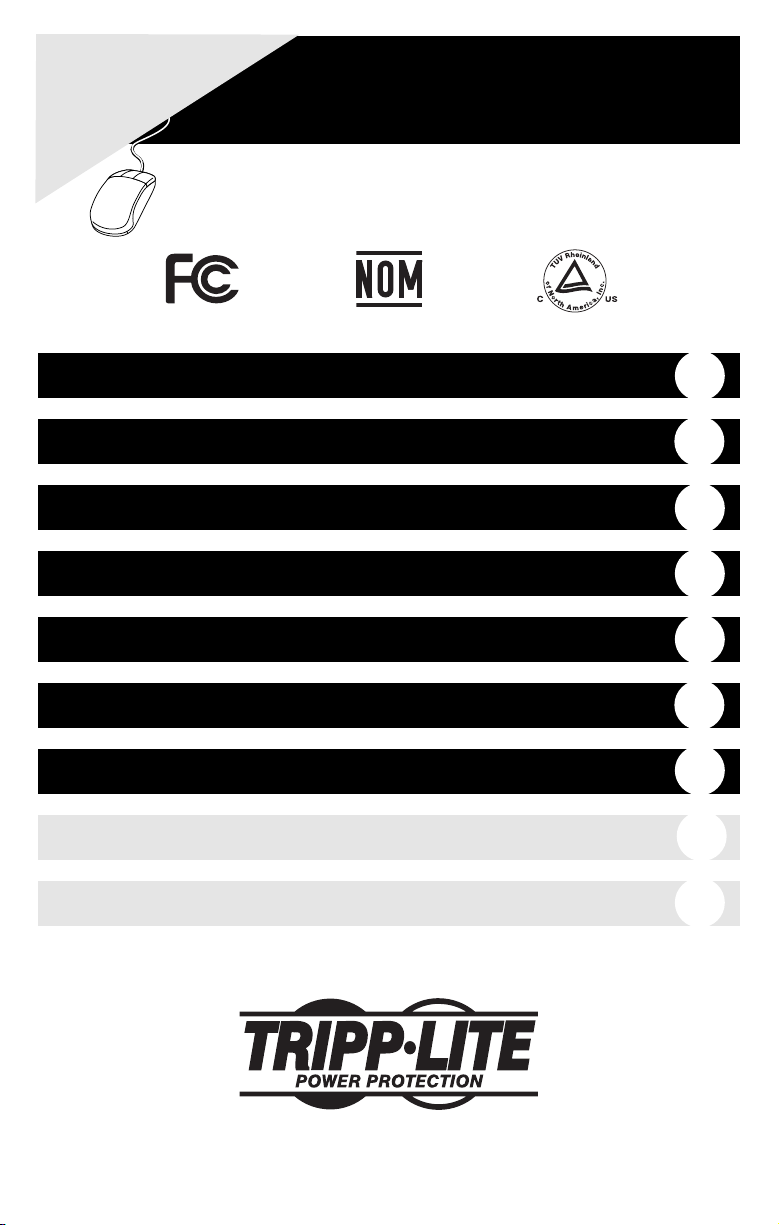
4-Post Mounting
All UPS models include hardware required to mount in a 4-post rack. Select models include an
adjustable rackmount shelf kit to provide additional support. If your UPS model does not
include an adjustable rackmount shelf kit, skip steps 1 and 2.
Connect the two segments of each shelf
1
using the included screws and nuts . Leave
the screws slightly loose so that the shelves
can be adjusted in the next step.
Adjust each shelf to fit your rack, then mount
2
them in the lowest available space of your
rack with the screws, nuts and washers
provided . Note that the support ledges
C
should face inward. Tighten the screws that
connect the shelf segments .
Attach mounting ears to the front
3
B
D
mounting holes of your equipment using
the screws provided . The ears should face
F
forward.
4
Using an assistant if necessary, lift your
equipment and slide it onto the mounting
shelves. Attach your equipment to the rack by
using the appropriate hardware through its
G
mounting ears and into the rack rails.
A
B
B
A
1
C
E
2
E
B
D
F
3
G
4
3
Page 4

Installation
2-Post (Telecom) Mounting
If you mount 2U UPS models in 2-post racks, they require the addition of a Tripp Lite 2-Post
Rackmount Installation Kit (model: 2POSTKITRMWM, sold separately). See Installation Kit
owner’s manual for installation procedure for 2U UPS models.
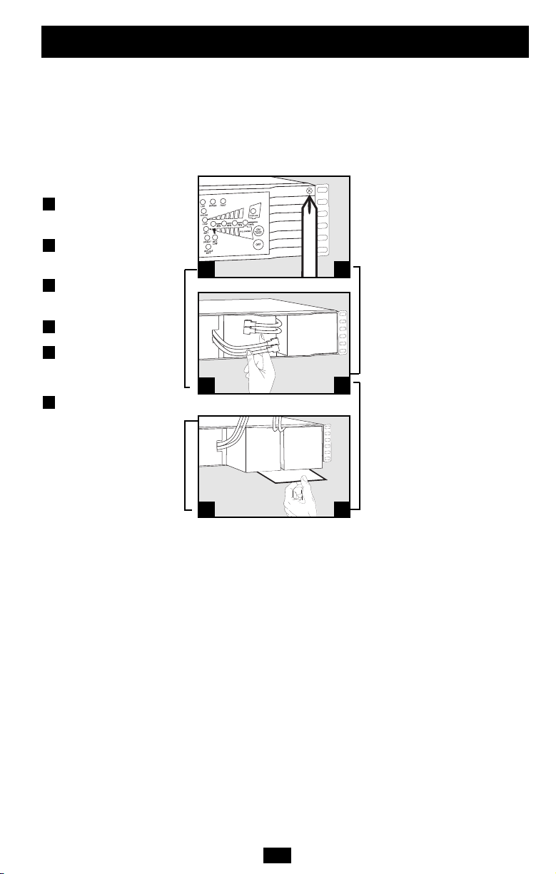
Mounting (Tower)
Your UPS can be mounted in an upright tower
position with optional base stands sold separately
by Tripp Lite (Model # 2-9USTAND). When
mounting the UPS on adjustable base stands,
make sure that the control panel is toward the top.
The control panel may be rotated to make it
easier to read. Insert a small screwdriver or
similar tool in the slots on either side of the panel,
pop it out, rotate it, and pop it back into place as
shown.
WARNING!
All UPS systems are extremely heavy. Use
caution when lifting and mounting. User must
properly stabilize the UPS when lifting and
mounting.
(continued)
4
Page 5
Important Safety Instructions
Installation
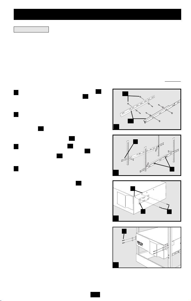
Connection and Start-Up
1
Plug your UPS’s line cord into an
(continued)
electrical outlet.
Your UPS must be connected to a dedicated
circuit of sufficient amperage. Note, however,
that the select models may be fitted with
different plug types. Refer to the “OP
Rating/Plug Rating” chart printed on the top of
your UPS.
Once your UPS is plugged in, the fan and all
Indicator Lights will turn ON. The “LINE” and
“LOAD ACTIVE METER” LEDs will
illuminate and the UPS will emit a beep to
indicate normal operation. However, power is
not supplied to your UPS’s AC outlets until the
UPS is turned on.
2
Plug your equipment into your UPS.
Your UPS is designed to support computer
equipment only. You will overload your UPS if
you connect household appliances or laser
printers to the UPS's outlets.
3
Turn your UPS ON:
• Press the “ON/TEST” Button
• Hold it for several seconds until you
hear a beep
• Release it
Your UPS will begin providing AC power to its outlets.
The “ON LINE” LED will illuminate.
Optional Connections
Your UPS will function properly without these
connections.
1
Phone Line or Phone/Network
Line Surge Suppression
Your UPS has jacks which protect against
surges on a phone line. Select models feature
jacks which also protect against surges on a
network line. Using appropriate telephone or
network cords connect your wall jack to the
UPS jack marked “IN.” Connect your
equipment to the UPS jack marked “OUT.”
Make sure the equipment you connect to the
UPS's jacks is also protected against surges on
the AC line.
5
Your model may differ.
1
Your model may differ.
2
3
1
Your model may differ.
Page 6
Installation
(continued)
Optional Connections
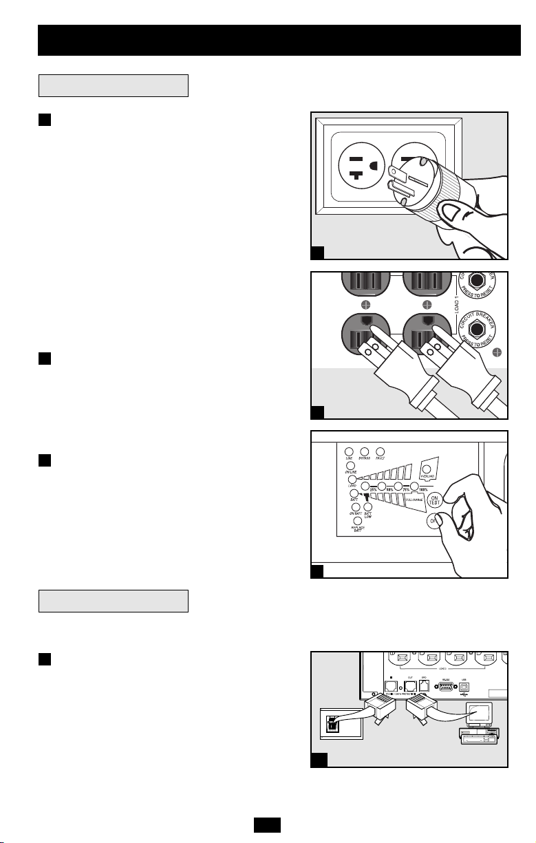
2
USB and RS-232 Serial
(continued)
Communications (all models)
Use the included USB cable (see ) and/or
DB9 serial cable (see ) to connect the
2b
communication port of your computer to the
communication port of your UPS. Install on
your computer the Tripp Lite PowerAlert
Software appropriate to your computer's
operating system. Your UPS may feature
additional communications ports; these ports
may be connected to additional computers that
have PowerAlert Software installed. Consult
your PowerAlert manual for more information.
3
EPO Port Connection (all models)
This optional feature is only for those
applications that require connection to a
facility's Emergency Power Off (EPO) circuit.
When the UPS is connected to this circuit, it
enables emergency shutdown of the UPS's
inverter. Using the cable provided, connect the
EPO port of your UPS (see ) to a usersupplied normally closed or normally open
switch according to the circuit diagram (see
3b
). The EPO port is not a phone line surge
suppressor; do not connect a phone line to
this port.
2a
3a
2a
Your model may differ.
2b
Your model may differ.
3a
Your model may differ.
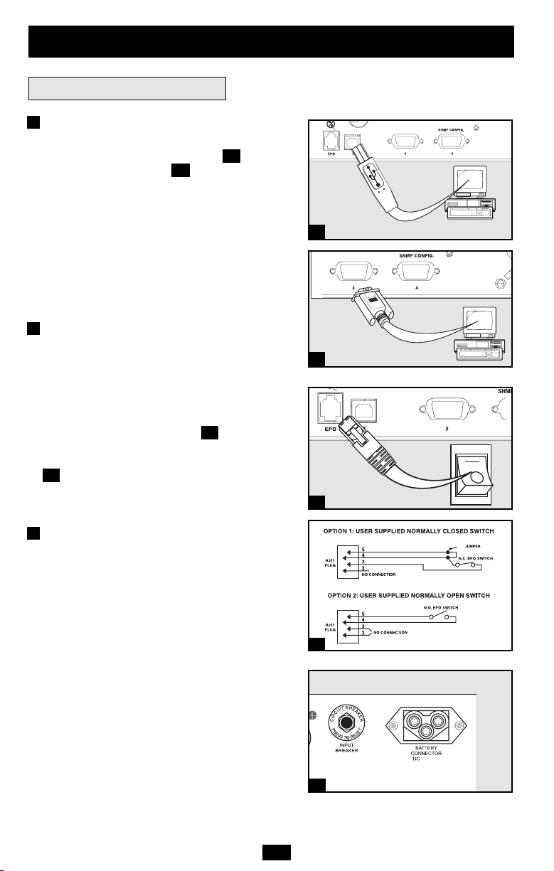
4
External Battery Connection
(select models)
Check to ensure that the external batteries you
are connecting match the voltage listed on
your UPS's battery connector. All UPS models
come with a robust internal battery system;
select models feature connectors that accept
optional external battery packs (sold separately
from Tripp Lite) to provide additional runtime.
Adding external batteries will increase
recharge time as well as runtime. See the
battery pack owner's manual for complete
installation instructions. Make sure cables are
fully inserted into their connectors. Small
sparks may result during battery connection;
this is normal. Do not connect or disconnect
battery packs when the UPS is running on
battery power.
4-5
3b
48V/26A
Your model may differ.
4
6
Page 7
Basic Operation
Front Panel Switches
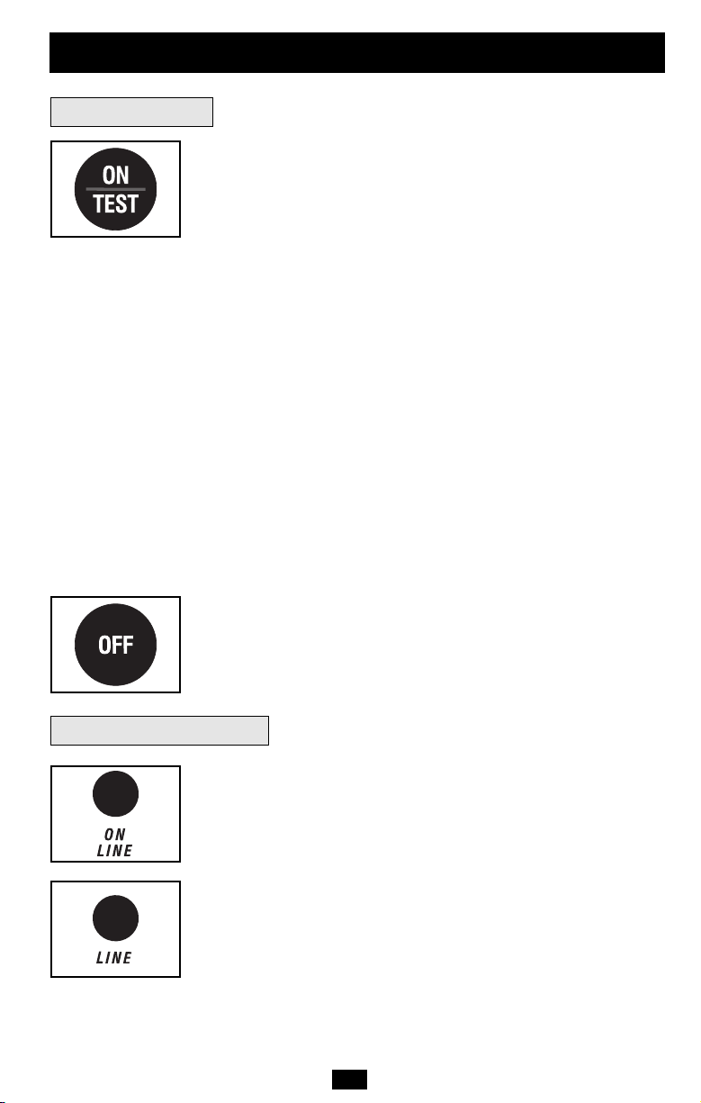
“ON/TEST” Button: This switch controls four separate UPS functions:
UPS Power ON
To turn the UPS on, press this button, hold it for several seconds until
you hear a beep, then release it. The “ON LINE” LED will illuminate.
UPS Self-Test
During normal on-line operation, press this button and hold it until
you hear a beep. This initiates a 10-second self-test of the battery. The
UPS will shift to battery power (all LEDs will illuminate) for ten
seconds.
Alarm Silence
To silence the UPS “on-battery” alarm, press this button and hold it
until you hear a beep.
UPS Cold Start
To use your UPS as a stand-alone power source when AC power is
unavailable (i.e. during a blackout), press this button and hold it until
you hear a beep. The UPS will then provide battery power to its outlets.*
* The “ON BATT” Indicator Light will be illuminated since your UPS will be operating
from battery power.
“OFF” Button: This button turns power OFF at the UPS receptacles.
Press this switch, hold it until you hear a beep, then release it. The
UPS will continue charging and the fan will continue to cool internal
components even after you turn the UPS receptacles off. To turn the
UPS OFF completely, including the charger, disconnect the UPS’s
power cord after pressing the “OFF” switch.
Front Panel Indicator Lights
“ON LINE” LED: This green light will illuminate constantly to indicate
the UPS is performing normal on-line operation (filtering and
resynthesizing incoming AC line voltage to provide pure sine wave
output). When this light is illuminated, you can monitor the load level
of your UPS on the “LOAD ACTIVE METER” LEDs.
“LINE” LED: This green light will illuminate constantly to indicate
the utility supplied AC line voltage at your wall outlet is nominal. It
will flash if the line voltage is outside the nominal range (either too
low or two high). No action is required on your part when the LED
flashes; the UPS continuously and automatically filters AC line
power to provide your equipment with pure sine wave AC power,
regardless of brownout or overvoltage conditions. If this light is off,
then AC line voltage is not present (blackout) or is at an extremely
high voltage, and the UPS will provide connected equipment with
power from battery.
7
Page 8
Basic Operation
(continued)
Front Panel Indicator Lights
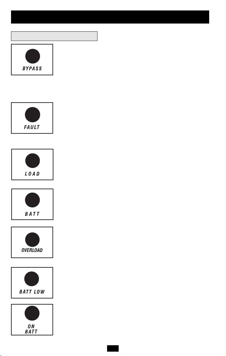
“BYPASS” LED: This yellow light will flash to indicate that the
UPS’s DC/AC inverter is deactivated and the UPS is in the “Bypass”
mode. During “Bypass” mode, the UPS will also beep every two
seconds, unless silenced by pressing the “ON/TEST” button. During
normal operation this LED will light briefly when the unit is plugged
in, but if an internal fault or overload occurs this light will flash
constantly to show that connected equipment will receive filtered AC
mains power, but will not receive battery power during a blackout. In
this case, contact Tripp Lite for service.
“FAULT” LED (select models only): This red light will flash when
your UPS detects an internal fault (overheating, overvoltages, etc.) or
when it detects a wiring fault in your wall outlet (reversed phases,
missing ground, etc.) The UPS will only detect wiring faults when it
is plugged into a utility outlet but not turned ON. If the light persists
after restarting the UPS, contact an electrician to check the AC line.
Your UPS will identify the presence of most (but not all) wiring faults.
“LOAD ACTIVE METER” LED: This green light will illuminate
when your UPS is receiving AC power to indicate that the set of four
dual-function LEDs is displaying the load level of your UPS.
“BATT ACTIVE METER” LED: This green light will illuminate
when your UPS is operating from battery power to indicate that the
set of four dual-function LEDs is displaying the battery charge level
of your UPS. Note: the “ON BATT” LED will also be illuminated.
continued
“OVERLOAD” LED: This red light will illuminate constantly to indicate
that your UPS’s capacity has been exceeded while it is in on-line operation.
The UPS alarm will beep continuously. Immediately remove overload
until light and alarm goes off. If you do not immediately remove the
overload, the UPS will transfer from on-line to bypass operation.
“BATT LOW” LED: This yellow light will illuminate when your UPS’s
battery charge level is low. The UPS alarm will beep until either the
battery charge is depleted or the batteries are adequately recharged.
“ON BATT” LED: This green light will illuminate constantly to
indicate that AC line voltage is not present and your UPS is providing
your equipment with battery power. The UPS will also beep every two
seconds, unless silenced by the “ON/TEST” Button. When this light
is illuminated, you can monitor the battery charge level of your UPS
on the “BATT ACTIVE METER” LEDs.
8
Page 9
Basic Operation
(continued)
Front Panel Indicator Lights
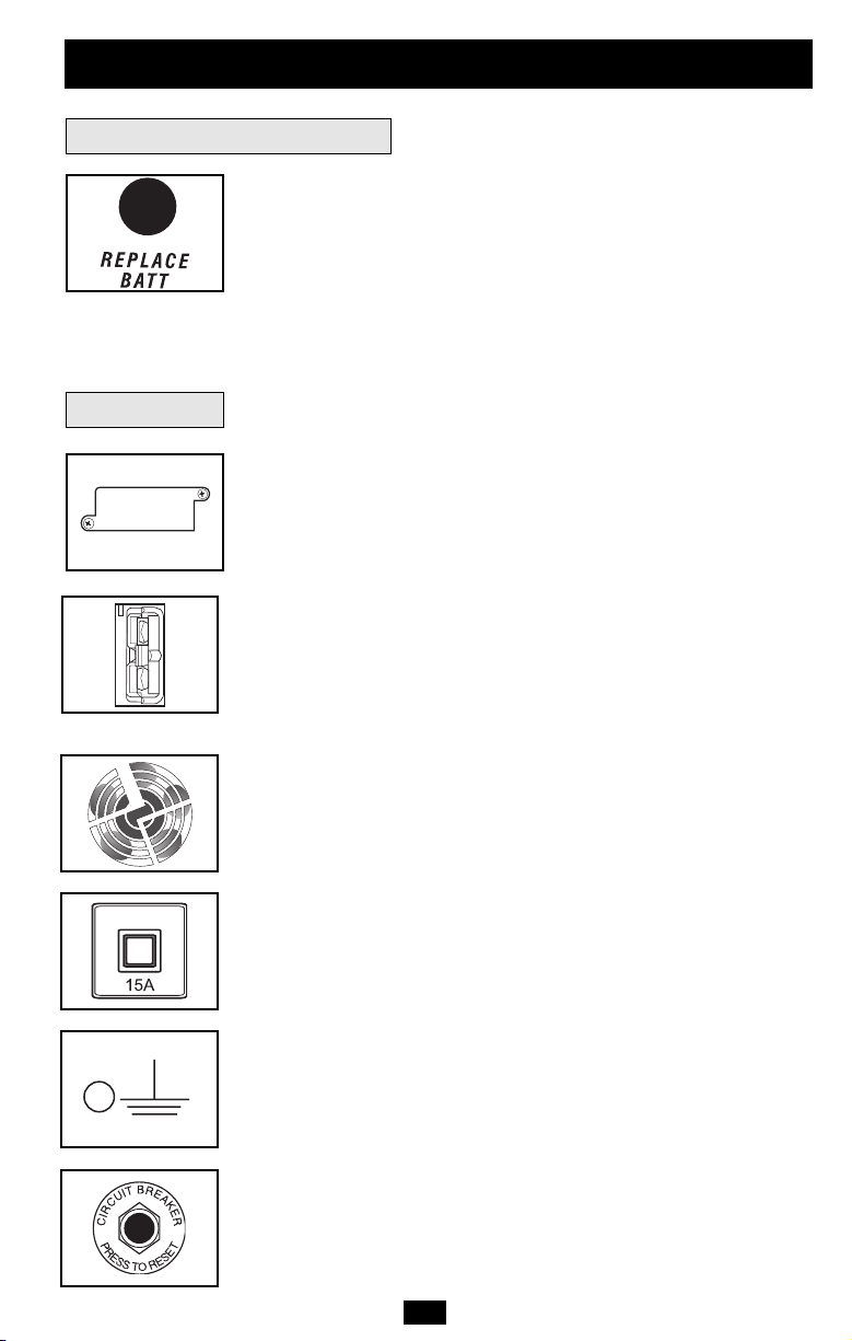
“REPLACE BATT” LED: This red light will illuminate constantly
and the UPS alarm will sound three beeps* if your UPS’s
microprocessor detects a battery fault or if your UPS fails the
automatic self-test (after you turn your UPS ON) and the UPS battery
is less than fully charged. Let the UPS system charge for at least 12
hours and perform a self test using the “ON/TEST Button” as described
on page 7. If the light continues to stay on, contact Tripp Lite for
service.
*After the initial alarm, the UPS will beep once every hour until the problem is corrected.
Rear Panel
Accessory Slot: Remove the small cover panel from this slot to use
optional accessories to remotely monitor and control your UPS.
Contact Tripp Lite Customer Support at (773) 869-1234 for more
information, including a list of available SNMP, network management
and connectivity products.
External Battery Pack Connector (configuration varies by model):
Use to connect optional Tripp Lite Battery Packs for additional
runtime. Contact Tripp Lite Customer Support at (773) 869-1234 for
the appropriate Tripp Lite battery pack to connect. Refer to
instructions available with the Battery Pack for complete connection
information and safety warnings.
Fan: The fan cools the UPS’s internal components. It is always on
when line power is present.
continued
Input Circuit Breaker Switch: This resettable breaker prevents high
input current from damaging the UPS or the attached load. If this
breaker trips, make sure your UPS is connected to AC power of the
proper voltage before resetting the circuit breaker by pushing the
breaker switch in.
Ground Screw: Use this to connect any equipment that requires a
chassis ground.
Output Circuit Breakers Switches (Select Models Only): These
resettable circuit breakers protect your UPS from output overload. If
one or both breakers trip, remove some of the load on the circuit(s)
and allow the UPS to cool before pressing the breaker switch(es) in
to reset.
9
Page 10
Basic Operation
(continued)
Rear Panel
NEMA 5-15R
NEMA 5-15/20R
Other outlet types not shown
Communications
continued
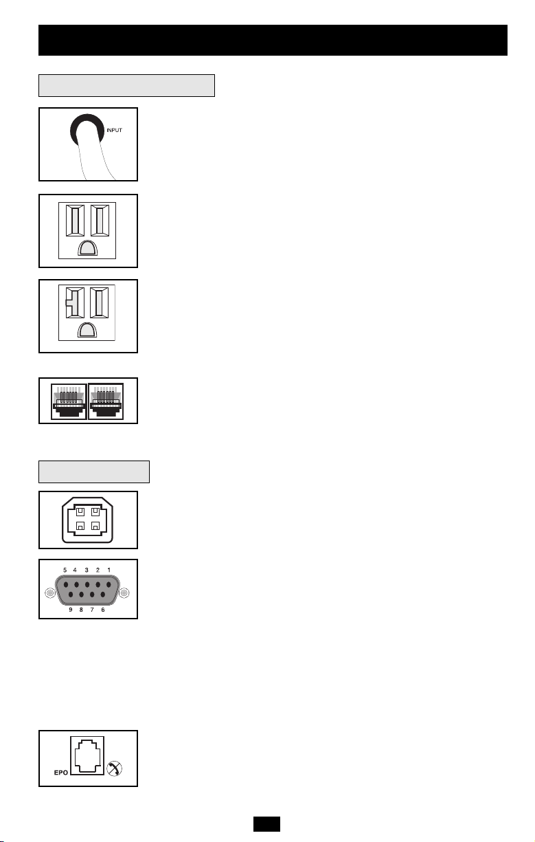
Input Cord: This permanently attached power cord connects your
UPS to a power outlet.
AC Receptacles (Varied by Model): These 15-, 20- and 30-amp
receptacles provide your connected equipment with pure sine-wave
AC output from the AC line during normal operation and from battery
power during blackouts and severe brownouts. Power provided at
these outlets is filtered to protect connected equipment against
damaging surges and line noise. The receptacles are divided into
numbered load banks, as labelled on the unit. Using PowerAlert
software and cabling, load banks one and two may be individually
turned off and on from a remote location, allowing users to reset or
reboot connected equipment.
Telephone or Telephone/Network Protection Jacks: These jacks
protect your equipment against surges over a telephone line or
telephone/network data line, depending on model. Connecting your
equipment to these jacks is optional. Your UPS will work properly
without this connection.
Not compatible with PoE (Power Over Ethernet) applications.
Communications Ports (USB or RS-232): These ports connect your
UPS to any workstation or server. Use with Tripp Lite’s PowerAlert
Software and included cables to enable your computer to
automatically save open files and shut down equipment during a
blackout. Also use PowerAlert Software to monitor a wide variety of
AC line power and UPS operating conditions. Consult your
PowerAlert Software manual or contact Tripp Lite Customer Support
for more information. See “USB and RS-232 Serial
Communications” in the “Optional Connections” section for
installation instructions.
Dry contact communications are simple, but some knowledge of
electronics is necessary to configure them. The DB9 port's pin
assignments are shown in the diagram. If the UPS battery is low, the
UPS sends a signal by bridging pins 1 and 5. If utility power fails, the
UPS sends a signal by bridging pins 8 and 5. To shut the UPS down
remotely, short pin 3~pin 9 for at least 3.8 seconds.
EPO (Emergency Power Off) Port: Your UPS features a EPO port
that may be used to connect the UPS to a contact closure switch to
enable emergency inverter shutdown. See Optional Installation.
10
Page 11

Troubleshooting
The UPS’s control panel lights will turn on in the sequences below to signal that the UPS is
having operational difficulties.
Note: The FAULT LED is only available on select models. If your UPS does not feature a FAULT LED, read the signals
described below by going to the next LED referenced. For example, on units with the FAULT LED, “Battery Voltage too
High” is indicated by illumination of both the FAULT and the REPLACE BATT LED's. On units without the FAULT
LED, the same condition is indicated by illumination of the REPLACE BATT LED only. Also note that units with no
FAULT LED cannot signal “Short Circuit” or “Wiring Fault” conditions.
Lights (On/Flashing) and Condition Solution
On: REPLACE BATT Let the UPS system charge for at least
Condition: Replace Battery 12 hours and perform a self test using
the "ON/Test Switch" as described on
page 7. If the light continues to stay on,
contact Tripp Lite for service.
On: BATT LOW, ON BATT Prepare for imminent UPS shutdown.
Condition: Battery Low
On: BYPASS, LINE, LOAD, OVERLOAD Reduce the load the UPS supports.
Condition: On Bypass due to Overload
On: FAULT Remove the cause of the short circuit
Condition: Short Circuit from the UPS output.
Flashing: FAULT Check the utility line for wiring problems
Condition: Wiring Fault such as reversed line and neutral or a
missing ground.
On: FAULT, REPLACE BATT Restart the UPS. If the problem persists,
Condition: Battery Voltage too High contact Tripp Lite for repairs.
On: FAULT, REPLACE BATT, OVERLOAD Restart the UPS. If the problem persists,
Condition: EEPROM Error contact Tripp Lite for repairs.
On: FAULT, BYPASS, LINE, 100% Restart the UPS. If the problem persists,
Condition: On Bypass due to contact Tripp Lite for repairs.
High Output Voltage
On: FAULT, BYPASS, LINE, 75% Restart the UPS. If the problem persists,
Condition: On Bypass due to contact Tripp Lite for repairs.
Low Output Voltage
On: FAULT, BYPASS, LINE, 50% Restart the UPS. If the problem persists,
Condition: On Bypass due to High contact Tripp Lite for repairs.
Bus Voltage
On: FAULT, BYPASS, LINE, 25% Restart the UPS. If the problem persists,
Condition: On Bypass due to Low contact Tripp Lite for repairs.
Bus Voltage
11
Page 12

Troubleshooting
Lights (On/Flashing) and Condition Solution
On: FAULT, BYPASS, LINE, 100%, 75% Check the UPS to be sure that there is
Condition: On Bypass due to High adequate space for air to circulate near
Internal Temperature the vents and that the fan is working
Flashing: LINE This indicates that utility power is too high
Condition: Input Abnormal or low for the UPS to operate in BYPASS
On: FAULT, 100% Restart the UPS. If the problem persists,
Flashing: LINE, BYPASS contact Tripp Lite for repairs.
Condition: No Output due to High
Output Voltage and Abnormal Input
(continued)
properly. Restart the UPS.
mode, so if an inverter failure occurs,
the UPS will deliver no output.
Flashing: LINE, BYPASS
On: FAULT, 7 5% contact Tripp Lite for repairs.
Condition: No Output due to Low
Output Voltage and Abnormal Input
Flashing: LINE, BYPASS Restart the UPS. If the problem persists,
On: FAULT, 5 0% contact Tripp Lite for repairs.
Condition: No Output due to High
Bus Voltage and Abnormal Input
Flashing: LINE, BYPASS Restart the UPS. If the problem persists,
On: FAULT, 2 5% contact Tripp Lite for repairs.
Condition: No Output due to Low
Bus Voltage and Abnormal Input
Flashing: LINE, BYPASS Check the UPS to be sure that there is
On: FAULT, 100%, 75% adequate space for air to circulate near
Condition: No Output due to High the vents and that the fan is working
Internal Temperature and Abnormal properly. Restart the UPS. If the problem
Input persists, contact Tripp Lite for repairs.
Restart the UPS. If the problem persists,
12
12
Page 13
Battery Replacement
Under normal conditions, the original batteries in your UPS will last many years. See Safety
section before replacing batteries. The batteries are designed for hot-swap replacement (i.e.
leaving the UPS in ON mode), but some qualified service personnel may wish to put the UPS
in the OFF mode and disconnect equipment before proceeding.
Procedure
1
Remove Front
Panel
2
Disconnect
Batteries
3
Remove/Dispose of
Batteries
4
Add Batteries
5
Connect Batteries
Attach connectors: black-
to-black and red-to-red.
6
Replace
Panel
Front
1
2
6
5
3
13
4
Page 14

Storage and Service
Storage
First turn your UPS OFF: press the “OFF” switch to turn power off at the UPS outlets, then
disconnect the power cord from the wall outlet. Next, disconnect all equipment to avoid battery
drain. If you plan on storing your UPS for an extended period of time, fully recharge the UPS
batteries once every three months by plugging the UPS into a live AC outlet and letting the
UPS charge for 4-6 hours. If you leave your UPS batteries discharged for an extended period
of time, they may suffer permanent loss of capacity.
Service
If returning your UPS to Tripp Lite, please carefully pack the UPS using the ORIGINAL
PACKING MATERIAL that came with the unit. Enclose a letter describing the symptoms of the
problem. If the UPS is within the 2 year warranty period, enclose a copy of your sales receipt.
Warranty Registration
Visit www.tripplite.com/warranty today to register the warranty for your new Tripp Lite product. You'll be automatically entered into a
drawing for a chance to win a FREE Tripp Lite product!*
Regulatory Compliance Identification Numbers: For the purpose of regulatory compliance certifications and identification, your Tripp
Lite product has been assigned a unique series number. The series number can be found on the product nameplate label, along with
all required approval markings and information. When requesting compliance information for this product, always refer to the series
number. The series number should not be confused with the marking name or model number of the product.
FCC Specifications for Models with FCC Approval: This device complies with part 15 of the FCC Rules. Operation is subject to the
following two conditions: (1) This device may not cause harmful interference, and (2) this device must accept any interference received,
including interference that may cause undesired operation.
This equipment has been tested and found to comply with the limits for a Class A digital device, pursuant to part 15 of the FCC Rules.
These limits are designed to provide reasonable protection against harmful interference when the equipment is operated in a commercial
environment. This equipment generates, uses, and can radiate radio frequency energy and, if not installed and used in accordance with
the instruction manual, may cause harmful interference to radio communications. Operation of this equipment in a residential area is likely
to cause harmful interference in which case the user will be required to correct the interference at his own expense. The user must use
shielded cables and connectors with this product. Any changes or modifications to this product not expressly approved by the party
responsible for compliance could void the user’s authority to operate the equipment.
FCC Part 68 Notice (United States Only): If your Modem/Fax Protection causes harm to the telephone network, the telephone
company may temporarily discontinue your service. If possible, they will notify you in advance. If advance notice isn't practical, you will
be notified as soon as possible. You will be advised of your right to file a complaint with the FCC. Your telephone company may make
changes in its facilities, equipment, operations or procedures that could affect the proper operation of your equipment. If it does, you
will be given advance notice to give you an opportunity to maintain uninterrupted service. If you experience trouble with this equipment's
Modem/Fax Protection, please call Tripp Lite Technical Support at (773) 869-1234 for repair/warranty information. The telephone
company may ask you to disconnect this equipment from the network until the problem has been corrected or you are sure the
equipment is not malfunctioning. There are no repairs that can be made by the customer to the Modem/Fax Protection. This equipment
may not be used on coin service provided by the telephone company. Connection to party lines is subject to state tariffs. (Contact your
state public utility commission or corporation commission for information.)
The policy of Tripp Lite is one of continuous improvement. Specifications are subject to change without notice.
This product designed and engineered in the USA.
* No purchase necessary. Void where prohibited. Some restrictions apply. See website for details.
14
Page 15

Manual del usuario
SmartOnline
™
Sistemas UPS en línea con montaje en bastidor/torre
No conveniente para los usos móviles.
Importantes instrucciones de seguridad
Instalación
Operación básica
Localización de fallas
Reemplazo de la batería
Almacenamiento y servicio
16
17
21
25
27
28
English
Français
1
29
1111 W. 35 th St re et Ch icago, IL 60609 EE.UU.
Atención al cliente: (773) 869-1234 • www.tripplite.com
© 2005 Tripp Lite. Todos los derechos reservados. SmartOnline™ es una marca registrada de Tripp Lite.
Page 16

Importantes instrucciones de seguridad
GUARDE ESTAS INSTRUCCIONES
Este manual contiene advertencias e instrucciones importantes que deben seguirse
durante la instalación, operación y almacenamiento de todos los sistemas UPS de Tripp Lite.
De no cumplirse estas advertencias, la garantía será anulada.
Advertencias sobre la colocación del UPS
• Instale el sistema UPS bajo techo, alejado del calor o la humedad excesivos, de los
contaminantes conductivos, del polvo o de la luz solar directa.
• Para lograr el mejor rendimiento, mantenga la temperatura interior entre 0º C y 40º C
(32º F y 104º F).
• Mantenga suficiente espacio alrededor del sistema UPS para permitir una ventilación
adecuada.
Advertencias sobre la conexión del UPS
• Conecte su sistema UPS directamente a una toma de corriente de CA con una conexión a
tierra adecuada. No conecte el sistema UPS a sí mismo, ya que esto lo dañará.
• No modifique los conectores del UPS y no utilice un adaptador que pueda eliminar la
conexión a tierra del sistema.
• No utilice cables de extensión para conectar el UPS en la toma de corriente de CA. Si se
utiliza otro tipo de supresor de sobretensión que no sea Tripp Lite para conectar el UPS a
la toma de corriente, se anulará la garantía del sistema.
• Si el sistema UPS recibe energía eléctrica por medio de un generador de CA accionado
por motor, éste deberá proporcionar una salida de corriente limpia y filtrada del tipo
utilizado para computadoras.
Advertencias sobre la conexión de equipos
• No utilice los sistemas UPS de Tripp Lite en equipo para el soporte de la vida humana,
donde un fallo o mal funcionamiento podría causar anomalías o alterar
significativamente el rendimiento del dispositivo para el soporte de la vida humana.
• No conecte supresores de sobretensión o cables de extensión a la salida del sistema UPS.
Esto podría dañar el UPS y anularía la garantía del supresor de sobretensiones y del UPS.
Advertencias sobre las baterías
Debido a que las baterías presentan un peligro de choque eléctrico y quemaduras por las
altas corrientes de cortocircuito, tome las precauciones adecuadas. No deseche las baterías
en un incinerador. No abra las baterías. No ponga los terminales de la batería en corto o en
puente con ningún objeto. Apague y desconecte el UPS antes de reemplazar la batería.
Sólo debe cambiar las baterías personal técnico debidamente capacitado. Use herramientas
con mangos aislados y reemplace las baterías existentes con el mismo número y tipo de
baterías nuevas (plomo-ácido selladas). Las baterías del UPS son reciclables. Consulte la
reglamentación local para los requisitos de disposición de desechos; para los EE.UU.
solamente consulte estas fuentes para información sobre reciclaje: 1-800-SAV-LEAD
(1-800-728-5323); 1-800-8-BATTERY (1-800-822-8837); www.rbrc.com. Tripp Lite
ofrece una línea completa de Cartuchos de reemplazo de batería para UPS (R.B.C.). Visite
Tripp Lite en la web en www.tripplite.com/support/battery/index.cfm para localizar la
batería de reemplazo específica para su UPS.
16
Page 17

Instalación
Monte su equipo en un bastidor de 2 o 4 postes (vea la siguiente página para información sobre el montaje
de 2 postes) El usuario debe determinar la idoneidad de los materiales y accesorios, así como de los
procedimientos antes del montaje. Si los materiales y procedimientos no son adecuados para su aplicación,
contacte con el fabricante de su bastidor. Los procedimientos descritos en este manual son para bastidores
comunes y de tipo caja y podrían no ser apropiados para todas las aplicaciones.
Montaje de 4 postes
Todos los modelos de UPS incluyen los accesorios requeridos para montar un bastidor de 4 postes. Los
modelos exclusivos incluyen un kit de anaquel ajustable para montaje en bastidor a fin de proporcionar un
apoyo adicional. Si su modelo de UPS no incluye este kit, omita los pasos 1 y 2.
Conecte los dos segmentos de cada anaquel
1
usando los tornillos y las tuercas de mariposa
incluidos. Deje los tornillos ligeramente flojos de
modo que los anaqueles puedan ajustarse en el
siguiente paso.
Ajuste cada anaquel para que se adapte a su
2
bastidor, y luego instálelos en el espacio más bajo
disponible del mismo con las tuercas, las
arandelas y los tornillos suministrados . Note
que los bordes de apoyo deben mirar
hacia adentro. Apriete los tornillos que conectan
los segmentos de los anaqueles .
Fije las orejas de montaje a los agujeros de
3
montaje de la parte delantera de su equipo
usando los tornillos suministrados . Las orejas
deben mirar hacia adelante.
Con la ayuda de otra persona si fuera necesario,
4
levante su equipo y deslícelo en los anaqueles de
montaje. Fije su equipo al bastidor usando los
accesorios suministrados a través de las orejas
de montaje y dentro de los
rieles del bastidor.
B
D
F
G
A
B
B
A
1
C
C
2
E
E
D
B
F
3
G
17
4
Page 18

Instalación
(continuación)
Montaje de 2 postes (Telecomunicaciones)
Monte los modelos de UPS de 1U en bastidores de 2 postes usando los accesorios incluidos y siguiendo el
procedimiento indicado a continuación.
Si monta un modelo de UPS de 2U en bastidores de 2 postes, necesitará agregar un kit de instalación para
montaje en bastidor de 2 postes de Tripp Lite (modelo: 2POSTKITRMWM, vendido por separado) Vea el
manual del propietario del kit para conocer el procedimiento de instalación en los modelos de 2U.
Montaje (en torre)
Todos los módulos pueden montarse en posición vertical, de
torre, cuando se emplean con bases de soporte ajustables
opcionales, vendidas por separado por Tripp Lite (modelo #: 29USTAND). Al montar módulos en las bases de soporte
ajustables asegúrese que el panel de control del módulo de
potencia esté hacia la parte superior. Además, si está instalando
un módulo de transformador, colóquelo entre el módulo de
potencia y su módulo de batería.
Gire el panel de control del módulo de potencia para obtener
mejor visibilidad mientras el UPS esté montado en torre.
Introduzca un pequeño destornillador u otra herramienta en las
ranuras en cualquier lado del panel de control. Saque el panel,
gírelo y colóquelo en posición nuevamente.
¡ADVERTENCIA!
¡Todos los módulos de no-break son muy pesados! ¡Tenga
cuidado al levantarlos y montarlos! ¡El usuario debe
estabilizar apropiadamente el módulo al levantarlo y
montarlo!
18
Page 19

Instalación
Conexión y encendido
1
Conecte el cable del sistema UPS
(continuación)
a una toma de corriente eléctrica.
Si su modelo tiene un cable de sistema
desmontable, conecte primero el extremo hembra
en el receptáculo de entrada de CA del UPS.
Su UPS debe estar conectado a un circuito
dedicado con un amperaje suficiente—
compruebe la gama de “Amperios de servicio
recomendados” de su modelo en las
especificaciones. Sin embargo, observe que los
modelos seleccionados pueden equiparse con
diferentes tipos de enchufe. Consulte la tabla
“Operación nominal/Conexión nominal”
impresa en la parte superior de su UPS.
Una vez que su UPS está enchufado, se encenderá
la luz del ventilador y todas las luces indicadoras.
Los LED “LINE” (Línea) y “LOAD ACTIVE
METER” (Medidor activo de carga) se encenderán
y el UPS emitirá un sonido que indica
funcionamiento normal. Sin embargo, no se
suministra energía a las tomas de corriente de CA
de su UPS hasta que se éste encienda.
2
Enchufe su equipo al sistema UPS.
Su sistema UPS está diseñado para soportar
únicamente equipo informático. Usted lo
sobrecargará si conecta electrodomésticos o
impresoras láser a las tomas de corriente del UPS.
Su modelo puede variar.
1
Su modelo
puede variar.
2
3
Encienda su sistema UPS (ON):
• Presione el interruptor “ON/TEST”
(Encendido/Prueba).
• Manténgalo presionado por varios segundos
hasta que escuche un sonido.
• Suelte el interruptor.
Su sistema UPS empezará a suministrar energía CA a sus tomas
de corriente. Se iluminará el LED “ON LINE” (En línea).
Conexiones opcionales
Este sistema UPS funcionará correctamente sin
estas conexiones.
1
Supresión de sobretensiones en
línea de teléfono o teléfono/red
Su UPS tiene conectores que lo protegen
contra sobretensiones en la línea telefónica.
Los modelos exclusivos tienen conectores que
también protegen contra sobretensiones en una
línea de red. Usando cordones adecuados para
teléfono o para red, conecte su conector de
pared al conector del UPS marcado “IN.”
19
3
1
Su modelo puede variar.
Page 20

Instalación
(continuación)
Conexiones opcionales
2
Conexión de Puerto USB y DB9
(continuación)
Con ayuda del cable USB proporcionado ( ),
conecte un puerto USB de una computadora a un
puerto USB del sistema UPS. Instale en la
computadora el software de protección de energía
de Tripp Lite que corresponda al sistema
operativo. Es posible conectar una Segunda
computadora al segundo puerto USB. Con ayuda
del cable DB9 ( ) proporcionado, conecte un
2b
puerto DB9 de su computadora a un puerto DB9
de su sistema UPS. Instale en la computadora el
software de protección de energía de Tripp Lite
que corresponda al sistema operativo. Se puede
conectar una Segunda computadora que tenga un
puerto DB9 al segundo puerto DB9.
3
Conexión con un puerto EPO
Con el cable RJ11 ( ) proporcionado, conecte
3a
el puerto para desconexión de emergencia (EPO)
del sistema UPS con un interruptor normalmente
abierto o cerrado, proporcionado por el usuario,
de acuerdo con el diagrama siguiente ( ). El
3b
puerto EPO no es un supresor de picos para
línea telefónica, por lo que no deberá
conectarlo con este tipo de líneas.
4
Conexión del paquete de baterías
externas
Verifique que las baterías externas que desea
conectar tengan el mismo voltaje de la lista que
aparece en el conector para baterías del UPS.
Conecte cualquier extremo del cable de conexión
de batería (proporcionado con el paquete de
baterías) en el conector para baterías externas del
UPS y el otro extremo en el conector de salida de
la batería que se encuentra en el panel posterior
del paquete de baterías externas. Debido a que su
UPS ya posee baterías internas, las baterías
externas son necesarias sólo para prolongar el
tiempo de funcionamiento. Si agrega baterías
externas incrementará el tiempo de recarga así
como el tiempo de respaldo. Asegúrese de que
cada extremo del cable esté completamente
insertado en su conector. Es normal que se
produzcan pequeñas chispas durante la conexión
de las baterías.
2a
2a
Su modelo puede variar.
2b
Su modelo puede variar.
3a
Su modelo puede variar.
3b
Su modelo puede variar.
4
4-5
48V/26A
20
Page 21

Operación básica
Interruptores del panel frontal
Interruptor “ON/TEST” (Encendido/Prueba): Este interruptor
controla cuatro funciones separadas del UPS:
UPS encendido: Para encender el UPS, presione el interruptor,
manténgalo presionado por varios segundos hasta que escuche un
sonido y suéltelo. Se encenderá el LED “ON LINE”.
Autoprueba del UPS: Durante una operación en línea normal,
presione el interruptor y manténgalo presionado hasta que escuche un
sonido. Esto inicia una autoprueba de la batería que dura 10
segundos. El UPS cambiará a energía de baterías (Todos los
indicadores se iluminaran) durante diez segundos.
Silenciar alarma: Para silenciar la alarma del UPS “en batería”,
presione el interruptor y manténgalo presionado hasta que escuche un
sonido.
Encendido en frío del UPS: Para usar su UPS como una fuente de
energía autónoma cuando no haya energía de CA disponible (es decir,
durante un apagón), presione este botón y manténgalo presionado
hasta que escuche un sonido. El UPS suministrará entonces energía de
las baterías a sus tomas de corriente.*
* La luz indicadora “ON BATT” se iluminará cuando su UPS esté operando con
energía de las baterías.
Interruptor “OFF” (Apagado): Este interruptor apaga el suministro
de energía en los receptáculos del UPS. Presione el interruptor,
manténgalo presionado hasta que escuche un sonido y suéltelo. El
UPS seguirá cargando y el ventilador seguirá enfriando los
componentes internos incluso después de haber apagado los
receptáculos del UPS. Para apagar completamente el UPS, incluido el
cargador, desconecte el cable de energía del UPS después de
presionar el interruptor “OFF”.
Luces indicadoras del panel frontal
LED “ON LINE”: Esta luz verde se iluminará y permanecerá fija para
indicar que el UPS está en operación en línea normal (filtrado y
resintetizado del voltaje de la línea de CA entrante para proporcionar
una salida en forma de onda sinusoidal pura). Cuando esta luz está
encendida, puede controlar el nivel de carga del UPS en los LED
“LOAD ACTIVE METER”.
LED “LINE” (Línea): Esta luz verde se iluminará y permanecerá
fija para indicar que el voltaje de la línea de CA proporcionada por el
suministro en su toma de energía es nominal. La luz parpadeará si el
voltaje de la línea se encuentra fuera del valor nominal (ya sea
demasiado bajo o demasiado alto). No necesita hacer nada cuando el
LED parpadea; el UPS filtra de manera continua y automática la
energía de la línea de CA para suministrar a su equipo energía de CA
de onda sinusoidal pura, sin considerar las condiciones de baja o alza
de voltaje. Si esta luz está apagada, quiere decir que no hay voltaje de
línea de CA (apagón) o que hay un voltaje muy alto y que el UPS
proporcionará energía a los equipos conectados desde la batería.
21
Page 22

Operación básica
(continuación)
Luces indicadoras del panel frontal
LED “BYPASS” (Derivación): Esta luz amarilla parpadea para
indicar que el inversor DC/AC del UPS esta desactivado y que el UPS
esta en modo “Bypass”. Durante el modo “Bypass”, el UPS también
sonara cada 2 segundos, amenos que sea silenciado por presionar el
botón “ON/TEST”. Durante la operación normal, este indicador
estará iluminado brevemente cuando la unidad sea conectada, pero si
una falla interna o sobrecarga ocurre, esta luz parpadeara
constantemente para mostrar que el equipo conectado recibirá
corriente alterna filtrada, pero no recibirá poder de baterías durante un
apagón. En este caso, contacte a Tripp Lite para servicio.
LED “FAULT” (Falla) (sólo en modelos exclusivos): Esta luz roja
parpadeará cuando su sistema UPS detecte una falla interna
(sobrecalentamiento, sobrevoltajes, etc.) o cuando detecte una falla de
cableado en las tomas de corriente (fases invertidas, ausencia de
tierra, etc.). El UPS detectará fallas de cableado sólo cuando se
encuentre conectado a una toma de energía eléctrica que no esté
encendida. Si la luz sigue encendida después de reiniciar el UPS,
comuníquese con un electricista para revisar la línea de CA. Su UPS
identificará la mayoría (pero no todas) las fallas de cableado.
LED “LOAD ACTIVE METER” (Medidor activo de carga): Esta
luz verde se encenderá cuando su UPS reciba energía de CA para
indicar que el grupo de cuatro luces LED de doble funcionalidad está
indicando el nivel de carga de su UPS.
LED “BATT ACTIVE METER” (Medidor activo de batería):
Esta luz verde se encenderá cuando su UPS funcione en base a la
energía de la batería para indicar que el grupo de cuatro luces LED de
doble funcionalidad está mostrando el nivel de carga de la batería de
su UPS. Nota: también se encenderá el LED “ON BATT”.
continuación
LED “OVERLOAD” (Sobrecarga): Esta luz roja se iluminará y
permanecerá fija para indicar que se excedió la capacidad de su UPS
mientras esté funcionando en línea. La alarma del UPS emitirá un sonido
continuo. Retire inmediatamente la sobrecarga hasta que se apague la
luz y la alarma. En caso de no retirar la sobrecarga inmediatamente, el
UPS cambiará de operación en línea a operación de derivación.
LED “BATT LOW” (Batería baja): Esta luz amarilla se encenderá
cuando el nivel de carga de la batería de su UPS esté bajo. La alarma
del UPS emitirá un sonido hasta que la carga de la batería se agote
completamente o se recarguen las baterías de manera adecuada.
LED “ON BATT” (En batería): Esta luz verde se iluminará y
permanecerá fija para indicar que no hay voltaje en la línea de CA y
que su UPS está suministrando energía al equipo a través de la batería.
El UPS emitirá un sonido cada dos segundos a menos que lo silencie
con el interruptor “ON/TEST”. Cuando se prende esta luz, puede
controlar el nivel de carga de la batería del UPS en los LED “BATT
ACTIVE METER”.
22
Page 23

Operación básica
(continuación)
Luces indicadoras del panel frontal
LED “REPLACE BATT” (Reemplazar batería): Esta luz roja se
iluminará y permanecerá fija y la alarma del UPS emitirá tres sonidos*
si el microprocesador del UPS detecta una falla en la batería o si su
UPS falla en la autoprueba automática (después de encendido) y en
caso de que la batería no esté completamente cargada. Deje que el
sistema del UPS se cargue por lo menos 12 horas y realice una
autoprueba usando el interruptor de " ON/Test " según lo descrito en
la página 21. Si la luz permanece encendida, póngase en contacto con
Tripp Lite para solicitar servicio técnico.
Panel posterior
*Después de la alarma inicial, el UPS emitirá un sonido cada hora hasta que se
solucione el problema.
Ranura para accesorios: Retire el pequeño panel que cubre esta
ranura para instalar accesorios opcionales utilizados en el monitoreo
y control remoto del sistema UPS. Póngase en contacto con el
Servicio de atención al cliente de Tripp Lite llamando al (773) 869-1234
para obtener más información, incluyendo una lista de los productos
disponibles de SNMP, de administración de redes y de conectividad.
Conector del paquete de baterías externas (varía por el modelo):
Utilícelo para conectar paquetes de baterías Tripp Lite opcionales si
desea tiempo de funcionamiento adicional. Póngase en contacto con
el Servicio de atención al cliente de Tripp Lite al (773) 869-1234 para
obtener el paquete de baterías Tripp Lite adecuado. Consulte las
instrucciones que vienen con el paquete de baterías para obtener
información completa sobre conexión y advertencias de seguridad.
continuación
Ventilador: El ventilador enfría los componentes internos del UPS.
Se encenderá siempre que haya energía de línea presente.
Interruptor de protección del mando del interruptor de entrada:
Este interruptor reconfigurable evita que una corriente de entrada alta
dañe el UPS o los aparatos conectados a él. Si este interruptor se
dispara, asegúrese de que el sistema UPS está conectado a una
energía de CA del voltaje adecuado antes de reconfigurar el
interruptor empujándolo hacia adentro.
Tornillo de tierra: Sirve para conectar equipo que requiere de una
tierra para chasís.
Interruptores de protección del mando del interruptorde salida
(sólo en modelos exclusivos): Estos interruptores reconfigurables
protegen su UPS de una sobrecarga de salida. Si uno o ambos
interruptores se dispararan, desconecte algunas de las cargas de los
circuitos y deje que el UPS se enfríe antes de presionar el o los
interruptores para restablecerlos.
23
Page 24

Operación básica
(continuación)
Panel posterior
NEMA 5-15R
NEMA 5-15/20R
No se muestran otros
tipos de salida
Comunicaciones
continuación
Cable de entrada: Este cable de energía con conexión fija, conecta
su UPS a una toma de corriente.
Receptáculos de CA (según modelo): Estos receptáculos de 15, 20 y
30 amperios le proporcionan a sus equipos salida de CA de onda
sinusoidal pura desde la línea de CA durante una operación normal y
energía desde las baterías durante apagones y severas bajas de voltaje.
La energía suministrada en estas tomas de corriente se filtra con el
objeto de proteger los equipos conectados contra daños y ruido de
línea. Los receptáculos se dividen en bancos de carga numerados,
como está rotulado en la unidad. Con el uso del software PowerAlert
y el cableado, se pueden encender y apagar individualmente los
bancos de carga uno y dos desde una ubicación remota, lo que le
permite a los usuarios restablecer o reiniciar los equipos conectados.
Vea Conexión de puerto serial en Conexiones opcionales.
Conectores de protección de teléfono o teléfono/red: Estos
conectores protegen su equipo contra sobretensiones a través de una
línea de teléfono o de teléfono/datos de red, dependiendo del modelo.
La conexión de su equipo con estos conectores es opcional. Su UPS
funcionará correctamente sin esta conexión.
No compatible con aplicaciones PoE (Energía sobre Ethernet).
Puertos de comunicaciones (USB o RS-232): Estos puertos conectan
su UPS a cualquier estación de trabajo o servidor. Úselos con el
software PowerAlert de Tripp Lite y los cables incluidos para permitir
que su computadora guarde automáticamente los archivos abiertos y
apague el equipo durante una falla del servicio eléctrico. También
utilice PowerAlert para vigilar una amplia variedad de condiciones de
operación de la energía de la línea de CA y del UPS. Consulte su
manual de PowerAlert o contacte con el Soporte al cliente de Tripp
Lite para mayor información. Consulte “Comunicaciones USB y serie
RS-232” en la sección “Instalación opcional” para obtener la
información sobre las instrucciones de instalación.
Las comunicaciones de contacto en seco son simples, pero se necesita
cierto conocimiento de electrónica para configurarlas. Las
asignaciones de las patillas del puerto DB9 se muestran en el
diagrama de la izquierda. Si la batería del UPS está baja, el UPS envía
una señal haciendo puente entre la patilla 1 y la 5. Si el suministro de
energía falla, el UPS manda una señal haciendo puente entre la patilla
8 y la 5. Para apagar el UPS remotamente, ponga en corto los pines
3~9 por 3.8 segundos al menos.
Puerto EPO (apagado de emergencia, Emergency Power-Off): El
sistema UPS cuenta con un puerto EPO mediante el cual se conecta
con un interruptor de cierre por contacto para la activación del paro
de emergencia del inversor. Véase Conexión.
24
24
Page 25

Localización de fallas
Las luces del panel de control del UPS se encenderán en las secuencias descritas a
continuación para indicar que el UPS tiene dificultades de funcionamiento.
Nota: El LED FAULT (FALLA) solo está disponible en modelos exclusivos. Si su UPS no cuenta con un LED FAULT,
lea las señales descritas a continuación en el siguiente LED referenciado. Por ejemplo, en unidades con el LED
FAULT, la condición “Voltaje de batería muy alto” se indica por el encendido de los LED FAULT (FALLA) y
REPLACE BATT (REEMPLAZAR BATERÍA). En unidades sin el LED FAULT, la misma condición es indicada
solamente por el encendido del LED REPLACE BATT (REEMPLAZAR BATERÍA). Observe además que las unidades
sin LED FAULT no pueden indicar condiciones de “Cortocircuito” o “Falla de cableado”.
Luces (Encendidas/Parpadeando) y condición Solución
Encendidas: REEMPLAZAR BATERÍA Deje que el sistema del UPS se
Condición: Reemplazar batería cargue por lo menos 12 horas y
Encendidas: BATERÍA BAJA, EN BATERÍA Prepárese para un apagado
Condición: Batería baja inminente del UPS.
Encendidas: DERIVACIÓN, LÍNEA, CARGA, Reduzca la carga que soporta
SOBRECARGA el UPS.
Condición: En Derivación por sobrecarga
Encendidas: FALLA Retire la causa del cortocircuito
Condición: Cortocircuito de la salida del UPS.
realice una autoprueba usando el
interruptor de " ON/Test " según lo
descrito en la página 21. Si la luz
permanece encendida, póngase
en contacto con Tripp Lite para
solicitar servicio técnico.
Parpadeando: FALLA Revise la línea de suministro
Condición: Falla de cableado para detectar problemas de
Encendidas: FALLA, REEMPLAZAR BATERÍA Reinicie el UPS. Si el problema
Condición: Voltaje de la batería demasiado alto persiste, póngase en contacto
Encendidas: FALLA, REEMPLAZAR BATERÍA, Reinicie el UPS. Si el problema
SOBRECARGA persiste, póngase en contacto
Condición: Error de EEPROM con Tripp Lite para solicitar
Encendidas: FALLA, DERIVACIÓN, LÍNEA, 100% Reinicie el UPS. Si el problema
Condición: En derivación debido a sobrevoltaje persiste, póngase en contacto
de salida con Tripp Lite para solicitar
Encendidas: FALLA, DERIVACIÓN, LÍNEA, 75% Reinicie el UPS. Si el problema
Condición: En derivación debido a bajo voltaje persiste, póngase en contacto
de salida con Tripp Lite para solicitar
Encendidas: FALLA, DERIVACIÓN, LÍNEA, 50% Reinicie el UPS. Si el problema
Condición: En derivación debido a sobrevoltaje persiste, póngase en contacto
en bus con Tripp Lite para solicitar
25
cableado como por ejemplo
línea invertida y neutra o
ausencia de conexión a tierra.
con Tripp Lite para solicitar
servicio técnico.
servicio técnico.
servicio técnico.
servicio técnico.
servicio técnico.
Page 26

Localización de fallas
Luces (Encendidas/Parpadeando) y condición Solución
Encendidas: FALLA, DERIVACIÓN, LÍNEA, 25% Reinicie el UPS. Si el problema
Condición: En derivación debido a bajo voltaje persiste, póngase en contacto
en bus con Tripp Lite para solicitar
Encendidas: FALLA, DERIVACIÓN, LÍNEA, Revise el UPS para asegurarse de
100%, 75% que hay suficiente espacio para
Condición: En derivación debido a alta permitir la circulación de aire
temperatura interna cerca de las ranuras de ventilación
Parpadeando: LÍNEA Esto indica que el suministro de
Condición: Entrada anormal energía es demasiado alto o bajo
Encendidas: FALLA, 100% Reinicie el UPS. Si el problema
Parpadeando: LÍNEA, DERIVACIÓN persiste, en contacto con Tripp Lite
Condición: No hay salida debido a un para solicitar servicio técnico.
sobrevoltaje de salida y entrada anormal
Parpadeando: LÍNEA, DERIVACIÓN Reinicie el UPS. Si el problema
Encendidas: FALLA, 75% persiste, póngase en contacto
Condición: No hay salida debido a un bajo con Tripp Lite para solicitar
voltaje de salida y entrada anormal servicio técnico.
Parpadeando: LÍNEA, DERIVACIÓN Reinicie el UPS. Si el problema
Encendidas: FALLA, 50% persiste, póngase en contacto
Condición: No hay salida debido a un con Tripp Lite para solicitar
sobrevoltaje en bus y entrada anormal servicio técnico.
Parpadeando: LÍNEA, DERIVACIÓN Reinicie el UPS. Si el problema
Encendidas: FALLA, 25% persiste, póngase en contacto
Condición: No hay salida debido a un bajo con Tripp Lite para solicitar
voltaje en bus y entrada anormal servicio técnico.
(continuación)
servicio técnico.
y que el ventilador esté funcionando
correctamente. Reinicie el UPS.
para que el UPS funcione en mod
o DERIVACIÓN, de modo que si
ocurre una falla del inversor, el UPS
no entregará energía de salida.
Parpadeando: LÍNEA, DERIVACIÓN Revise el UPS para asegurarse de
Encendidas: FALLA, 100%, 75% que hay suficiente espacio para
Condición: No hay salida debido a una alta permitir la circulación de aire
temperatura interna y entrada anormal cerca de las ranuras de ventilación
26
26
y que el ventilador esté funcionando
correctamente. Reinicie el UPS. Si
el problema persiste, póngase en
contacto conTripp Lite para
solicitar servicio técnico.
Page 27

Reemplazo de batería
Bajo circunstancias normales, las baterías originales de su UPS durarán muchos años. Vea la sección
Seguridad antes de reemplazar las baterías. Las baterías están diseñadas para su reemplazo en operación
(es decir, con el UPS encendido), aunque el personal de servicio calificado pueda preferir apagar el UPS
antes de proceder.
Procedimiento
1
Retire el panel
frontal
2
Desconecte las
baterías
3
Retire/deseche las
baterías
4
Agregue las baterías
5
Conecte las baterías
Asegure los conectores:
negro-a-negro y rojo-arojo.
6
Recoloque el panel
frontal
Modelos de UPS de 2U
1
2
6
5
3
27
4
Page 28

Almacenamiento y servicio
Almacenamiento
Primero, apague el sistema UPS: presione el interruptor “OFF” para desconectar la
alimentación en las tomas del UPS, luego desconecte el cable de alimentación de la toma de
corriente. Después, desconecte todos sus equipos para evitar el desgaste innecesario de la batería.
Si desea almacenar este sistema UPS por un período prolongado, recargue completamente las
baterías del sistema UPS una vez cada tres meses, conectándolo a una línea de CA que tenga
corriente y permitiéndole que cargue sus baterías por un período de 4 a 6 horas. Si deja las
baterías del sistema UPS descargadas por un periodo de tiempo prolongado, pueden perder su
capacidad en forma permanente.
Servicio
Si decide devolver su UPS a Tripp Lite, embale cuidadosamente el sistema UPS usando el
MATERIAL DE EMBALAJE ORIGINAL que se proporcionó con la unidad. Adjunte una carta
describiendo los síntomas del problema. Si el sistema UPS se encuentra dentro del periodo de
garantía de 2 años, adjunte una copia de su nota de compra.
Cumplimiento de las normas de los números de identificación:
Tripp Lite tiene asignado un número de serie único. Puede encontrar el número de serie en la etiqueta de la placa de identificación del producto, junto con
los símbolos de aprobación e información requeridos. Al solicitar información sobre el cumplimiento de las normas para este producto, siempre mencione el
número de serie. El número de serie no debe ser confundido con el nombre de identificación ni con el número de modelo del producto.
Especificaciones de FCC para modelos con certificación de la FCC: Este dispositivo cumple con la sección 15 de las reglas de la FCC. La operación
adecuada está sujeta a las siguientes dos condiciones: (1) Este dispositivo no debe causar interferencias dañinas y (2) este dispositivo debe aceptar
cualquier interferencia recibida, incluyendo la interferencia que podría causar una operación no intencional.
Nota: Se ha comprobado que este dispositivo cumple con los límites designados para un dispositivo digital de la Clase A de acuerdo con la parte 15 de las
Regulaciones de FCC. Estos límites se diseñaron para proporcionar protección razonable contra interferencias perjudiciales cuando la unidad es operada
en entornos comerciales. Este equipo genera, utiliza y puede radiar energía de radio frecuencia y, si no es instalado y utilizado de acuerdo con las
instrucciones del manual de operación, puede causar interferencias perjudiciales a las comunicaciones de radio. La operación de este equipo en un área
residencial puede causar interferencias perjudiciales. En tal caso, se puede requerir que el usuario corrija dichas interferencias y sea responsable por los
costos de esta corrección. El usuario debe utilizar en este producto conectores y cables blindados. Cualquier cambio o modificación a este producto, no
aprobados de manera expresa, por parte del responsable del cumplimiento de las normas, invalidará la autorización del usuario para operar el equipo.
La política de Tripp Lite es de mejora continua. La ficha técnica está sujeta a cambios sin previo aviso.
LEA SU INSTRUCTIVO CONSULTE SUS CONDICIONES DE GARANTIA POR PRODUCTO POLIZA DE GARANTIA
Este equipo marca Tripp Lite, modelo _______________ está garantizado por TRIPP LITE DE MEXICO, S. de R.L. de C.V., que tiene su domicilio en la
calle de Jaime Balmes No.11-801-C, Col Los Morales, CP 11510, Mexico, DF, y puede hacer efectiva su garantia asi como obtener partes, componentes,
consumibles y accesorios en el Centro de Servicio Q PLUS ubicado en Av Coyoacan 931, Col. Del Valle, C.P. 03120 México. D.F., tel. 55 59 30 22 contra
cualquier defecto de fabricación y funcionamiento, imperfecciones de materiales, piezas, componentes y mano de obra, por un lapso de dos años a partir
de la fecha de entrega.
CONDICIONES
1. Para hacer válida su garantía no podran exigirse mayores requisitos que la presentación de esta poliza junto con el producto en el lugar donde fue
adquirido.
2. TRIPP LITE, se compromete a reparar, y en caso de que a su juicio no sea posible la reparación, a cambiar el equipo, así como las piezas y
componentes defectuosos del mismo sin cargo alguno para el propietario durante el periodo de garantia, asi como los gastos de transportacion del
producto que deriven de su cumplimiento, dentro de su red de servicio.
3. El tiempo de reparación en ningún caso será mayor de 30 días contados a partir de la fecha de recepción del producto en el Centro Autorizado de
Servicio, en donde tambien podran adquirir refacciones y partes.
4. En caso de que la presente poliza de garantía se extraviara, el consumidor puede recurrir a su proveedor para que expida un duplicado de la póliza de
garantía, previa presentación de la nota de compra o factura correspondiente.
EXCLUSIONES
Esta garantía no es válida en los siguientes casos:
a) Cuando el producto se hubiese utilizado en condiciones distintas a la normales.
b) Cuando el producto no hubiese sido operado de acuerdo con el instructivo de uso que se le acompaña.
c) Cuando el producto hubiese sido alterado o reparado or personas no autorizadas por el fabricante nacional, importador o comercializador responsable
respectivo.
Esta garantía también podrá hacerse efectiva en el establecimiento donde el presente equipo haya sido adquirido.
Este equipo fue vendido por: _____________________________________ con domicilio en ________________________________________________
el día _____ de ___________ de ________, fecha a partir de la que inicia la presente garantía.
Este producto ha sido creado y diseqado en EE.UU.
Para fines de identificación y certificación del cumplimiento de las normas, su producto
28
Page 29

Guide de l'utilisateur
SmartOnline
™
Système UPS à montage en ligne en châssis vertical ou en bâti
Non approprié aux applications mobiles.
Importantes consignes de sécurité
Installation
Exploitation de base
Dépannage
Remplacement des batteries
Entreposage et entretien
30
31
35
39
41
42
English
Español
1
15
1111 W. 35th Street, Chicago, IL 60609 USA
Service à la clientèle : 1 (773) 869-1234 • www.tripplite.com
© Tripp Lite, 2005. Tous droits réservés. SmartOnline™est une marque de commerce de Tripp Lite.
Page 30

Importantes consignes de sécurité
CONSERVEZ CES INSTRUCTIONS EN UN LIEU SÛR
Le présent guide contient des instructions et des mises en garde qui doivent être suivies lors de
l'installation, de l'exploitation et de l'entreposage de tous les systèmes UPS Tripp Lite. Ne pas tenir
compte de ces mises en garde annule la garantie.
Mises en garde relatives à l'emplacement du système UPS
• Installez votre système UPS à l'intérieur, loin de l'humidité, de la chaleur excessive, des
impuretés conductrices, de la poussière et de la lumière directe du soleil.
• Pour un meilleur rendement, maintenez la température ambiante entre 0 ºC et 40 ºC
(32 ºF et 104 ºF).
• Laissez suffisamment d'espace autour du système UPS pour maintenir une bonne ventilation.
Mises en garde relatives au raccord du système UPS
• Branchez directement votre système UPS à une prise de courant alternatif munie d'un contact
de mise à la terre. Ne branchez pas votre système UPS sur lui-même car ceci l'endommagera.
• Ne modifiez pas la prise du système UPS et n’utilisez pas un adaptateur qui rendrait la
connexion de mise à la terre du système inopérante.
• N'utilisez pas de rallonges électriques lors du branchement du système UPS à une prise c.a.
Votre garantie sera annulée si le branchement s'effectue à l'aide de suppresseurs de surtension
autres que ceux fabriqués par Tripp Lite.
• Si votre système UPS est alimenté par une génératrice de courant alternatif, celle-ci devra
fournir un courant filtré et sans parasites convenant au matériel informatique.
Mises en garde relatives au raccord de l'équipement
• Ne raccordez pas les systèmes UPS Tripp Lite à des appareils de soutien vital si leur
dysfonctionnement ou leur défaillance peut causer une panne ou nuire de manière significative
à l'efficacité de ces dispositifs.
• Ne connectez pas de suppresseurs de surtension ou de rallonges électriques à la prise de votre
système UPS. De tels branchements peuvent l’endommager et entraîner une annulation de sa
garantie tout comme celle couvrant le suppresseur de surtension.
Mises en garde relatives à la batterie
Parce que les batteries présentent un risque de choc électrique et de courant de court-circuit
élevé, prenez les précautions nécessaires. Ne pas jeter les batteries au feu. Ne pas ouvrir les
batteries. Ne pas établir de court-circuit ou de pont entre les bornes de la batterie avec un
quelqconque objet. Débrancher et éteindre l'UPS avant de remplacer la batterie. Le remplacement
de la batterie doit être confié à du personnel de service qualifié. Utiliser des outils ayant des
poignées isolées et remplacer les batteries existantes par des batteries neuves du même numéro et
du même type (batterie sans entretien). Les batteries UPS sont recyclables. Consultez les codes
locaux concernant les exigences d'élimination des déchets, ou au E.-U.seulement, consultez ces
sources pour des renseignements concernant le recyclage : 1-800-SAV-LEAD (1-800-728-5323);
1-800-8-BATTERY (1-800-822-8837); www.rbrc.com. Tripp Lite offre une gamme complète
decartouches de batterie de remplacement de système UPS (R.B.C.). Rendez visite à Tripp Lite
sur le Web à www.tripplite.com/support/battery/index.cfm pour trouver la batterie de
remplacement spécifique à votre UPS.
30
Page 31

Installation
Installer votre équipement dans un bâti à quatre ou à deux montants ou dans une baie (voir à la page
suivante pour l'installation à deux montants) L'utilisateur doit déterminer la compatibilité de la
quincaillerie et les procédures avant d'effectuer l'installation. Si la quincaillerie et les procédures ne
conviennent pas à votre application, communiquer avec le fabricant de votre bâti ou baie. Les
procédures décrites dans ce manuel s'appliquent à des types courants de bâti et baies et peuvent ne
pas être appropriés pour toutes les applications.
Bâti à quatre montants
Tous les modèles UPS comprennent la quincaillerie nécessaire au montage dans un bâti à quatre
montants. Les modèles sélect comprennent un kit d'étagères réglables de montage en bâti pour fournir
un soutien supplémentaire. Si votre UPS ne comprend pas de kit d'étagères réglables, sauter les
étapes 1 et 2.
Assembler les deux parties de chaque étagère
1
A
en utilisant les vis et les écrous . Laisser
les vis légèrement desserrées de façon à
pouvoir régler les étagères durant l'étape
suivante.
Régler chaque étagère pour qu'elle s'ajuste à
2
votre bâti, puis les monter dans l'espace
disponible inférieur de votre bâti avec les vis,
écrous et rondelles fournis . Noter que les
C
traverses de soutien doivent faire face à
l'intérieur. Serrer les vis qui assemblent les
parties d'étagères .
Fixer les oreilles de montage aux trous de
3
montage de votre équipement en utilisant
les vis fournies . Les oreilles doivent faire
B
D
E
F
face vers l'avant.
Avec l'aide d'un assistant, si nécessaire,
4
soulever votre équipement et le faire glisser
dans les étagères. Fixer votre équipement au
bâti en utilisant la quincaillerie appropriée à
travers les oreilles de montage et dans les rails
du bâti.
B
B
A
1
C
2
E
D
B
F
3
G
G
31
4
Page 32

Installation
(suite)
Montage sur 2 montants (Télécom)
Monter les modèles UPS U1 dans des bâtis à 2 montants avec la quincaillerie fournie en suivant la
procédure ci-dessous.
Si vous montez des modèles UPS U2 dans des bâti à 2 montants, vous aurez besoin du kit d'installation
de montage en bâti à 2 montants de Tripp Lite (modèle 2POSTKITRMWM, vendu séparément). Voir
le manuel du propriétaire du kit d'installation pour la procédure d'installation des modèles UPS 2U.
Montage (Tour)
Faire tourner le Panneau de Commande du module
d'alimentation pour le voir plus facilementquand le
Système d'alimentation continue sans coupure est monté
en tour. Insérer un petit tournevis, ou un autre outil, dans
les slots de chaque côté du Panneau de Commande.
Dégager le panneau ; le faire tourner ; et remettre en place
le panneau. Tous les modules doivent être installés en
position debout lorsque utilisés avec une base ajustable
optionnelle, vendue séparément par Tripp Lite (modèle
no. 2-9USTAND). Lorsque vous installez un module sur
une base ajustable, assurez-vous que le panneau de
contrôle du module d'alimentation se trouve sur le coté
supérieur. Si vous installez aussi un module de
transformateur, placez-le entre le module d'alimentation
et son module à piles.
AVERTISSEMENT!
Tous les modules de système UPS sont extrêmement
lourds ! Faites attention lorsque vous les soulevez ou
les installez! L'utilisateur doit stabiliser adéquatement
le module lorsqu'il le soulève ou l'installe.
32
Page 33

Installation
Connexion et démarrage
1
Branchez le cordon d'alimentation
(suite)
de votre système UPS dans une
prise de courant.
Si votre modèle est doté d’un cordon
d’alimentation amovible, branchez d’abord le côté
femelle dans la prise d’entrée c.a. du système UPS.
Votre système UPS doit être branché à un circuit
spécialisé possédant une intensité de courant
électrique suffisante—consultez la rubrique
Intensité de courant électrique recommandée
pour votre modèle dans la section traitant des
spécifications. Il est à noter que plusieurs types
de fiches peuvent convenir aux modèles choisis.
Reportez-vous au tableau de régime nominal de
fonctionnement/de fiche sur le dessus de votre
système UPS.
Une fois le système UPS branché, le ventilateur
et tous les voyants s’allument. Les voyants «
LINE » (ALIMENTATION) et « LOAD ACTIVE
METER » (INDICATEUR DE CHARGE
ACTIVE) s’allument et le système UPS émet un
signal sonore pour indiquer qu’il fonctionne
normalement. Les prises c.a. de votre système
UPS ne sont toutefois pas alimentées en courant
tant que le système UPS n’est pas allumé.
2
Branchez votre matériel dans votre
système UPS.
Votre système UPS n'est conçu que pour accepter
du matériel informatique. Vous surchargerez
votre système UPS si vous branchez des
appareils électroménagers ou des imprimantes
laser à ses prises de courant.
3
Mettez votre système UPS en
marche :
• Appuyez sur le commutateur « ON/TEST »
(MARCHE/TEST)
• Maintenez-le enfoncé pendant plusieurs secondes
jusqu’à ce que vous entendiez un signal sonore
• Relâchez-le
Votre système UPS commence à alimenter ses prises en tension
c.a. Le voyant « ON LINE » (ALIMENTATION) s’allume.
Votre modèle peut être différent.
1
Votre modèle
2
peut être différent.
3
33
Page 34

Installation
(suite)
Connexions facultatives
(suite)
Votre système UPS fonctionnera correctement sans
ces connexions.
Suppression de la surtension de ligne
1
téléphonique ou ligne téléphone/réseau
Votre UPS est doté de prises qui protègent des
surtensions de lignes téléphoniques. Certains
modèles sélectionnés offrent des prises qui
protègent également contre les surtensions de ligne
de réseau. Avec les fils de téléphone ou fils réseaux
appropriés, branchez votre prise murale à la prise
UPS marquée “IN” (entrée).
2
Connexion du port USB et du port
série DB9
En utilisant le câble USB fourni, reliez le port USB
2a
(
) de l'ordinateur à celui de votre système UPS.
Installez dans l'ordinateur le logiciel de protection de
l'alimentation électrique Tripp Lite adapté à son
système d'exploitation. Un second ordinateur USB
peut être connecté au deuxième port USB, si désiré.
En utilisant le câble DB9 (
série DB9 de votre ordinateur à celui de votre
système UPS. Installez dans l'ordinateur le logiciel
de protection de l'alimentation électrique Tripp Lite
adapté à son système d'exploitation. Un second
ordinateur muni d'un port série DB9 peut être
connecté au deuxième port DB9, si désiré.
3
Connexion du port d'arrêt d'urgence
En utilisant le câble RJ11 ( ) fourni, reliez le port
d'arrêt d'urgence de votre système UPS à un
commutateur normalement fermé ou normalement
ouvert fourni par l'utilisateur selon le schéma de
circuit ci-dessous ( ). Le port d'arrêt d'urgence
n'est pas un suppresseur de surtension de ligne
téléphonique; ne relies aucune ligne
téléphonique à ce port.
4
Branchement d'un bloc-batterie externe
Assurez-vous que les batteries externes que vous
reliez correspondent à la tension inscrite sur le
connecteur de batterie du système UPS. Branchez
l’une des deux extrémités du câble de connexion
(fourni avec le bloc-batterie) dans le connecteur de
batterie externe du système UPS et l’autre
extrémité dans le connecteur de sortie de la batterie
situé sur le panneau arrière du bloc-batterie externe.
Puisque votre système UPS dispose de batteries
internes, les batteries externes ne sont utiles que
pour augmenter la durée d’exécution. L’ajout de
batteries externes allongera le temps de recharge
ainsi que la durée d'exécution. Assurez-vous que
chaque extrémité du câble est complètement
insérée dans son connecteur. Il est normal que la
connexion du bloc-batterie produise de petites
étincelles.
3b
2b
) fourni, reliez le port
3a
34
1
Votre modèle peut être différent.
2a
Votre modèle peut être différent.
2b
Votre modèle peut être différent.
3a
Votre modèle peut être différent.
3b
Votre modèle peut être différent.
4
4-5
48V/26A
Page 35

Exploitation de base
Commutateurs du panneau avant
Commutateur « ON/TEST » (MARCHE/TEST) : Le commutateur
commande quatre fonctions distinctes du système UPS :
Mise en fonction du système UPS : Pour allumer le système UPS, appuyez sur
le commutateur et maintenez-le enfoncé pendant plusieurs secondes
jusqu’à ce que vous entendiez un signal sonore puis relâchez-le. Le
voyant « ON LINE » (ALIMENTATION) s’allume.
Autotest du système UPS : En cours d’exploitation en ligne normale,
appuyez sur le commutateur et maintenez-le enfoncé jusqu’à ce que vous
entendiez un signal sonore. Cette procédure lance un autotest de la
batterie d’une durée de 10 secondes. Le système UPS passera en mode
d’exploitation de la batterie (tous les DELs vont s'allumer) pendant 10
secondes.
Interruption de l’alarme : Pour interrompre l’alarme du système UPS
signalant l’exploitation en mode de batterie, appuyez sur le commutateur
et maintenez-le enfoncé jusqu’à ce que vous entendiez un signal sonore.
Démarrage à froid du système UPS : Pour utiliser votre système UPS
comme source d’alimentation autonome lorsque l’alimentation en c.a.
n’est pas disponible (c’est-à-dire durant une panne de courant), appuyez
sur le commutateur et maintenez-le enfoncé jusqu’à ce que vous
entendiez un signal sonore. Le système UPS alimentera ses prises par
l’intermédiaire de sa batterie.*
* Le voyant « ON BATT » (BATTERIE EN FONCTION) s’allume puisque votre
système UPS est alimenté par la batterie.
Commutateur « OFF » (ARRÊT) : Ce commutateur coupe la mise
sous tension des prises de courant du système UPS. Appuyez sur le
commutateur jusqu’à ce que vous entendiez un signal sonore puis
relâchez-le. Le système UPS continuera de charger la batterie et le
ventilateur continuera de refroidir les composants internes après que vous
aurez coupé la mise sous tension des prises du système UPS. Pour couper
complètement l’alimentation du système UPS, y compris l’alimentation
du chargeur, débranchez le cordon d’alimentation après avoir appuyé sur
le commutateur « OFF » (ARRÊT).
Voyants du panneau avant
VOYANT DEL « ON LINE » (ALIMENTATION) : Ce voyant vert
s’allume constamment pour signaler que le système UPS fonctionne
normalement en mode d’exploitation en ligne (en filtrant et en
resynthétisant la tension de ligne à c.a.. pour fournir une onde sinusoïdale
de sortie pure). Lorsque ce voyant est allumé, vous pouvez surveiller le
niveau de charge de la batterie de votre système UPS à l’aide des voyants
DEL « LOAD ACTIVE METER » (INDICATEUR DE CHARGE ACTIVE).
VOYANT DEL « LINE » (ALIMENTATION) : Ce voyant vert
s’allume constamment pour indiquer que la tension de la ligne à c.a. de la
prise murale est nominale. Il clignote si la tension de ligne se situe à
l’extérieur de la plage nominale (si elle est trop basse ou trop élevée).
Aucune action ne doit être prise de votre part si les voyants DEL
clignotent; le système UPS filtre automatiquement et continuellement la
ligne à c.a. pour fournir une onde sinusoïdale pure en tension c.a., peu
importe les baisses de tension ou les surtensions. Si le voyant est éteint, la
tension de la ligne à c.a. n’alimente pas le système (panne de courant) ou
présente une tension extrêmement élevée. Le système UPS alimente alors
l’équipement à partir de la batterie.
35
Page 36

Exploitation de base
(suite)
Voyants du panneau avant
VOYANT « BYPASS » (ÉVITEMENT) : Ce voyant jaune va flasher
pour indiquer que l'inverseur DC/AC inverter est désactivé et que l'UPS est
sur le mode « Bypass ». Pendant le mode « Bypass », l'UPS va aussi
beeper toutes les deux secondes, à moins qu'il soit silencé en pressant le
bouton « ON/TEST ». Pendant l'opération normale, ce DEL va s'illuminer
brièvement lorsque l'unité est branchée, mais si un défaut ou une surcharge
interne se produit, ce voyant va flasher de manière constante pour montrer
que le matériel connecté va recevoir l'alimentation principale CA filtrée,
mais ne recevra pas l'alimentation par batterie pendant une coupure de
courant. Dans ce cas, veuillez contacter Tripp Lite pour le service.
VOYANT DEL « FAULT » (DÉFAILLANCE) (modèles choisis
seulement) : Ce voyant rouge clignote lorsque le système UPS détecte
une défaillance interne (surchauffe, surtensions, etc.) ou un problème de
câblage dans les prises murales (phases inversées, absence de mise à la
terre, etc.) Le système UPS ne détecte les problèmes de câblage que
lorsqu’il est branché dans une prise de courant, mais qu’il n’est pas
allumé. Si le voyant ne s’éteint pas après avoir redémarré le système UPS,
communiquez avec un électricien pour qu’il vérifie la ligne à c.a. Votre
système UPS est en mesure de détecter la présence de la plupart des
problèmes de câblage, mais pas tous.
VOYANT DEL « LOAD ACTIVE METER » (INDICATEUR DE
CHARGE ACTIVE) : Ce voyant vert s’allume lorsque le système UPS
reçoit de l’alimentation électrique en courant alternatif pour indiquer que
le jeu des quatre voyants à double fonction affichent le niveau de charge
de votre système UPS.
VOYANT DEL « BATT ACTIVE METER » (CHARGE DE
BATTERIE ACTIVE) : Ce voyant vert s’allume lorsque le système UPS
reçoit de l’alimentation électrique de la batterie pour indiquer que le jeu
des quatre voyants DEL à double fonction affichent le niveau de charge de
la batterie de votre système UPS. Remarque : le voyant DEL « ON
BATT » (BATTERIE EN FONCTION) s’allume aussi.
suite
VOYANT DEL « OVERLOAD » (SURCHARGE) : Ce voyant rouge
s’allume constamment pour indiquer que la capacité de votre système
UPS a été dépassée lorsqu’il fournit une exploitation en ligne. L’alarme
sonore du système UPS retentit continuellement. Éliminez immédiatement
la surcharge jusqu’à ce que le voyant et l’alarme s’éteignent. Si vous ne
supprimez pas immédiatement la surcharge, le système UPS passera de
l’exploitation en ligne à l’exploitation en mode d’évitement.
VOYANT « BATT LOW » (CHARGE FAIBLE) : Ce voyant jaune
s’allume lorsque la charge de la batterie du système UPS est faible. L’alarme
sonore du système UPS retentit jusqu’à ce que la charge de la batterie soit
épuisée ou que les batteries soient adéquatement rechargées.
VOYANT DEL « ON BATT » (BATTERIE EN FONCTION) : Ce
témoin vert s’allume constamment pour indiquer que la tension de ligne à
c.a. n’est pas présente et que le système UPS alimente votre matériel à
l’aide de la charge de la batterie. Le système UPS se fera également
entendre à toutes les deux secondes, à moins qu’il soit interrompu à l’aide
du commutateur « ON/TEST » (MARCHE/TEST). Lorsque ce voyant
est allumé, vous pouvez surveiller le niveau de charge de la batterie de votre
système UPS à l’aide des voyants DEL « BATT ACTIVE METER »
(INDICATEUR DE BATTERIE ACTIVE).
36
Page 37

Exploitation de base
(suite)
Voyants du panneau avant
VOYANT DEL « REPLACE BATT » (REMPLACER LA
BATTERIE) : Ce voyant rouge s’allume constamment et l’alarme du
système UPS émet trois signaux sonores* si le microprocesseur du
système UPS détecte une défaillance de batterie ou si l’autotest du
système UPS échoue (après que vous allumez votre système UPS) et que
la batterie du système UPS n’est pas complètement chargée. Laisser
l'UPS recharger pendant au moins 12 heures et effectuer un auto-test en
utilisant le commutateur "ON/Test" comme décrit en page 35. Si le
voyant est toujours allumé, communiquez avec le service à la clientèle de
Tripp Lite.
*Après le signal sonore initial, le système UPS continue de se faire entendre à toutes les
Panneau arrière
heures jusqu’à ce que la défaillance soit corrigée.
Fente à accessoires : Enlevez le petit volet de cette fente pour installer
des accessoires optionnels de surveillance et de gestion de votre système
UPS. Communiquez avec le service à la clientèle de Tripp Lite au (773)
869-1234 pour plus de détails, incluant une liste des produits SNMP, de
gestion de réseau et de connectivité offerts.
Connecteur pour bloc-batterie externe (varie par le modèle) : Utilisezle pour relier des blocs-batteries Tripp Lite supplémentaires de manière à
augmenter la durée d'exécution. Communiquez avec le service à la
clientèle de Tripp Lite au (773) 869-1234 pour connaître le bloc-batterie
Tripp Lite approprié à brancher. Consultez le guide de l'utilisateur fourni
avec le bloc-batterie externe pour les instructions complètes relatives à
son installation et les précautions à prendre.
Ventilateur : Le ventilateur refroidit les composants internes du système
UPS. Il est toujours en fonction lorsque l’alimentation secteur est
présente.
suite
Commutateur de disjoncteur du circuit d’entrée : Ce disjoncteur à
réenclenchement empêche que du courant d'entrée élevé endommage le
système UPS ainsi que le matériel qui y est branché. Si ce disjoncteur se
déclenche, assurez-vous que votre système UPS est branché à une prise
d’alimentation en c.a. d’une tension appropriée avant de réarmer le
disjoncteur en appuyant sur son commutateur.
Vis de borne de terre : Utilisez cette dernière pour relier tout matériel
qui exige une prise de terre de châssis.
Commutateurs de disjoncteurs de sortie (modèles choisis seulement) :
Ces disjoncteurs à réenclenchement protègent votre système UPS contre
une surcharge en sortie. Si un ou les deux disjoncteurs se déclenchent,
enlevez du matériel branché et laissez le système UPS refroidir avant
d'appuyer sur les commutateurs des disjoncteurs pour les réarmer.
37
Page 38

Exploitation de base
(suite)
Panneau arrière
NEMA 5-15R
NEMA 5-15/20R
Autres types de prises non
illustrées
Communications
suite
Cordon d’entrée : Ce cordon d’alimentation, fixé en permanence,
raccorde votre système UPS à une prise de courant.
Prises c.a. (varient selon les modèles) : Ces prises de 15, 20 et 30
ampères fournissent au matériel branché une onde sinusoïdale de sortie à
c.a. pure provenant d’une ligne à c.a. lors d’un fonctionnement normal et
de la batterie durant les pannes de courant et les baisses de tension
importantes. Le courant fourni au niveau de ces prises est filtré pour
protéger le matériel contre les surtensions préjudiciables et le bruit de
ligne. Ces prises sont divisées en blocs de charge numérotés, tels
qu’indiqués sur l’appareil. À l’aide du logiciel PowerAlert et du câblage,
les blocs de charge un et deux peuvent être activés et désactivés
séparément à distance pour permettre aux utilisateurs de réinitialiser le
matériel branché. Reportez-vous à la rubrique traitant du branchement des
ports série de la section Connexions facultatives.
Prises de protection ligne téléphonique ou téléphone/réseau : ces
prises protègent votre équipement contre les surtensions des lignes de
transmission de données téléphoniques ou téléphone/réseau, selon le
modèle. Brancher vos équipements à ces prises est optionnel. Votre UPS
fonctionnera correctement même sans cette connexion.
Non compatible avec les ports Ethernet alimentés en courant
Ports de communication (USB ou RS-232) : Ces ports connectent votre
UPS à n'importe quelle station de travail ou serveur. Les utiliser avec le
logiciel PowerAlert de Tripp Lite et les câbles inclus pour permettre à votre
ordinateur de sauvegarder automatiquement les fichiers ouverts et de mettre
votre équipement hors tension pendant une panne. Utiliser aussi le logiciel
PowerAlert pour surveiller une grande variété de conditions de
fonctionnement du secteur et de l'UPS. Consulter votre manuel du logiciel
PowerAlert ou communiquer avec le service à la clientèle de Tripp Lite pour
plus de renseignements. Voir “Communications de série USB et RS-232”
dans la section “Installation en option” pour les directives d'installation.
Les communications à contact sec sont simples à utiliser, mais une
certaine connaissance de l'électronique est nécessaire pour les configurer.
Les assignations de broches du port DB9 sont illustrées dans le
diagramme de gauche. Si la batterie du système UPS est faible, celui-ci
envoie un signal en branchant les broches 1 et 5 en parallèle. Si
l'alimentation est coupée, le système UPS envoie un signal en branchant
les broches 8 et 5 en parallèle. Pour fermer l'UPS à distance, retenir la
broche 3~broche 9 pendant au moins 3.8 secondes.
Port d'arrêt d'urgence (EPO) : Votre système UPS comprend un port
d'arrêt d'urgence qui peut être utilisé pour relier le système UPS à un
commutateur de fermeture de circuit pour permettre l'arrêt du
convertisseur de secours. Voir la section Connexion.
38
Page 39

Dépannage
Les voyants du panneau de configuration du système UPS s’allument selon la séquence ci-dessous
pour indiquer que le système UPS ne fonctionne pas normalement.
Remarque :La DEL DE DÉFAILLANCE est seulement disponible pour les modèles choisis. Si votre UPS de dispose pas
d'une DEL DE DÉFAILLANCE, lire les signaux décrits ci-dessous en allant à la DEL indiquée suivante. Par exemple,
sur les unités disposant d'une DEL DE DÉFAILLANCE, la DEL DE DÉFAILLANCE et la DEL DE REMPLACEMENT
DE BATTERIE s'allument pour indiquer une " Tension de batterie trop élevée "; sur les unités sans DEL DE
DÉFAILLANCE, seule la DEL DE REMPLACEMENT DE BATTERIE est allumée pour indiquer le même état. Noter
aussi que les unités sans DEL DE DÉFAILLANCE ne peuvent signaler les états de " court-circuit " ou de " défaut de
câblage "
Voyants (allumés/clignotent) et problème Solution
Allumés : REPLACE BATT(REMPLACER Laisser l'UPS recharger pendant
LA BATTERIE) au moins 12 heures et effectuer un
Problème : Remplacez la batterie. auto-test en utilisant le commutateur
Allumés : BATT LOW, ON BATT (BATTERIE Attendez-vous à ce que le système
FAIBLE, BATTERIE EN FONCTION) UPS cesse de fonctionner sous peu.
Problème : Batterie faible
Allumés : BYPASS, LINE, LOAD, OVERLOAD Réduisez la charge du système UPS.
(ÉVITEMENT, ALIMENTATION, CHARGE,
SURCHARGE)
Problème : En mode d’évitement en raison
d’une surcharge
"ON/Test" comme décrit en page
35. Si le voyant est toujours allumé,
communiquez avec le service à la
clientèle de Tripp Lite.
Allumés : FAULT (DÉFAILLANCE) Corrigez la cause du court-circuit
Problème : Court-circuit à la sortie du système UPS.
Clignotent : FAULT (DÉFAILLANCE) Vérifiez l’alimentation électrique
Problème : Problèmes de câblage pour vous assurer de l’absence
Allumés : FAULT, REPLACE BATT Redémarrez le système UPS. Si le
(DÉFAILLANCE, REMPLACER LA BATTERIE) problème persiste, consultez leservice
Problème : Tension de la batterie trop élevée à la clientèle de Tripp Lite.
Allumés : FAULT, REPLACE BATT, OVERLOAD Redémarrez le système UPS. Si le
(DÉFAILLANCE, REMPLACER LA BATTERIE, problème persiste, consultez le
SURCHARGE) service à la clientèle de Tripp Lite.
Problème : Erreur de la mémoire EEPROM
Allumés : FAULT, BYPASS, LINE (DÉFAILLANCE, Redémarrez le système UPS. Si le
ÉVITEMENT, ALIMENTATION), 100 % problème persiste, consultez le
Problème : En mode d’évitement en raison service à la clientèle de Tripp Lite.
d’une tension de sortie élevée
Allumés : FAULT, BYPASS, LINE (DÉFAILLANCE, Redémarrez le système UPS. Si le
ÉVITEMENT, ALIMENTATION), 75 % problème persiste, consultez le
Problème : En mode d’évitement en raison service à la clientèle de Tripp Lite.
d’une tension de sortie basse
39
de problèmes de câblage comme
une ligne inversée et neutre ou
une absence de mise à la terre.
Page 40

Dépannage
Voyants (allumés/clignotent) et problème Solution
Allumés : FAULT, BYPASS, LINE (DÉFAILLANCE, Redémarrez le système UPS. Si le
ÉVITEMENT, ALIMENTATION), 50 % problème persiste, consultez le
Problème : En mode d’évitement en raison service à la clientèle de Tripp Lite.
d’une tension de source élevée
Allumés : FAULT, BYPASS, LINE (DÉFAILLANCE, Redémarrez le système UPS. Si le
ÉVITEMENT, ALIMENTATION) 25 % problème persiste, consultez le
Problème : En mode d’évitement en raison service à la clientèle de Tripp Lite.
d’une tension de source basse
Allumés : FAULT, BYPASS, LINE (DÉFAILLANCE, Assurez-vous qu’il y a suffisamment
ÉVITEMENT, ALIMENTATION), 100 %, 75 % d’espace autour du système UPS
Problème : En mode d’évitement en raison pour que l’air circule près des
d’une température interne élevée évents et que le ventilateur
Clignotent : LINE (ALIMENTATION) Cela indique que la puissance
Problème : Entrée anormale électrique est trop élevée ou trop
Allumés : FAULT (DÉFAILLANCE), 100 % Redémarrez le système. Si le
Clignotent : LINE, BYPASS (ALIMENTATION, problème persiste, consultez le
ÉVITEMENT) service à la clientèle de Tripp Lite.
Problème : Aucune sortie en raison d’une
tension de sortie élevée et d’une entrée anormale
(suite)
fonctionne correctement. Redémarrez
le système UPS.
basse pour que le système UPS
puisse fonctionner en mode
d’évitement. Si un convertisseur
tombe en panne, le système
UPS ne pourra pas alimenter le
matériel qui y est branché.
Clignotent : LINE, BYPASS (ALIMENTATION, Redémarrez le système UPS. Si le
ÉVITEMENT) problème persiste, consultez le
Allumés : DÉFAILLANCE (FAULT), 75 % service à la clientèle de Tripp Lite.
Problème : Aucune sortie en raison d’une
tension de sortie faible et d’une entrée anormale
Clignotent : LINE, BYPASS (ALIMENTATION, Redémarrez le système UPS. Si le
ÉVITEMENT) problème persiste, consultez le
Allumés : FAULT (DÉFAILLANCE), 50 % service à la clientèle de Tripp Lite.
Problème : Aucune sortie en raison d’une tension
de source élevée et d’une entrée anormale
Clignotent : LINE, BYPASS (ALIMENTATION, Redémarrez le système ups. Si le
ÉVITEMENT) problème persiste, consultez le
Allumés : FAULT (DÉFAILLANCE), 25 % service à la clientèle de Tripp Lite.
Problème : Aucune sortie en raison d’une tension
de source basse et d’une entrée anormale
Clignotent : LINE, BYPASS (ALIMENTATION, Assurez-vous qu’il y a suffisamment
ÉVITEMENT) d’espace autour du système UPS
Allumés : FAULT (DÉFAILLANCE), 100 %, 75 % pour que l’air circule près des évents
Problème : Aucune sortie en raison d’une et que le ventilateur fonctionne
température interne élevée et d’une entrée anormale correctement. Redémarrez le
40
système UPS. Si le problème
persiste, consultez le service à la
clientèle de Tripp Lite.
Page 41

Remplacement des batteries
Dans des conditions normales, la batterie d'origine de votre UPS durera plusieurs années. Voir la section
sécurité avant de remplacer les batteries. Les batteries sont conçues pour le remplacement à chaud (c.-à-d.
l'UPS étant en marche), mais le personnel de service qualifié préfèrera mettre l'UPS à l'arrêt avant de
procéder.
Procédure
1
Enlever le panneau
avant
2
Déconnecter les
batteries
3
Enlever ou disposer
des batteries
4
Ajouter des batteries
5
Connecter les batteries
Relier les connecteurs :
noir-noir et rouge-rouge
6
Replacer le panneau
avant
Modèles UPS 2U
1
2
3
6
5
4
41
Page 42

Entreposage et entretien
Entreposage
Veuillez d’abord éteindre votre système UPS : appuyez sur le commutateur « OFF »
(ARRÊT) pour couper l’alimentation électrique au niveau des prises du système UPS puis
débranchez le cordon d’alimentation de la prise murale. Débranchez ensuite tout le matériel pour
éviter d’épuiser la batterie. Si vous envisagez d'entreposer votre système UPS pour une période
prolongée, rechargez complètement les batteries à tous les trois mois en branchant le système à
une prise de secteur pendant 4 ou 6 heures. Si vous laissez les batteries de votre système UPS
déchargées pendant une période de temps extrêmement longue, elles souffriront d'une perte
permanente de capacité.
Entretien
Si vous retournez votre système UPS à Tripp Lite, veuillez le remballer en utilisant le
MATÉRIEL D'EMBALLAGE D’ORIGINE livré avec l'unité. Joignez-y une lettre décrivant les
symptômes du problème. Si votre système UPS est couvert par sa garantie de deux ans,
joignez-y une copie de votre facture.
Spécifications de la FCC pour les modèles homologués par la FCC : Ce périphérique est conforme à la
section 15 des règlements de la FCC. Son utilisation est assujettie aux deux conditions suivantes : (1) Ce
périphérique ne peut pas produire de brouillage nuisible, et (2) il doit accepter tout brouillage reçu, y compris
ceux qui peuvent avoir des effets préjudiciables.
Ce matériel a été testé et s’est avéré être conforme aux limites des dispositifs numériques de Classe A,
conformément à la partie 15 du règlement de la FCC. Ces limites sont conçues pour fournir à une installation
commerciale une protection raisonnable contre les brouillages nuisibles.Ce matériel produit, utilise et peut émettre
de l’énergie de fréquence radio et s’il n’est pas installé et utilisé conformément au guide d'instructions, celui-ci
peut causer un brouillage dans les communications radio. L'utilisation de ce matériel dans un secteur résidentiel
peut causer un brouillage nuisible qui devra être corrigé au frais de l'utilisateur. L'utilisateur doit faire usage de
câbles et de connecteurs blindés avec ce produit.Tout changement ou toute modification apportés à ce produit
qui ne sont pas expressément acceptés par la partie responsable de la conformité aux normes peuvent
annuler le droit de l'utilisateur d'exploiter cet équipement.
Numéros d'identification de conformité aux règlements : À des fins de certification et d'identification de
conformité aux règlements, votre produit Tripp Lite a reçu un numéro de série unique. Ce numéro se retrouve
sur la plaque signalétique du produit, avec les inscriptions et informations d'approbation requises. Lors d'une
demande d'information de conformité pour ce produit, utilisez toujours le numéro de série. Il ne doit pas être
confondu avec le nom de la marque ou le numéro de modèle du produit.
L’amélioration constante des produits sert de fondement à la politique de Tripp Lite. Les spécifications ci-jointes
peuvent être modifiées sans préavis.
Ce produit a été conçu et fabriqué aux États-Unis.
42
Page 43

43
Page 44

1111 W. 35th Street Chicago, IL 60609 USA
Customer Support: (773) 869-1234 • www.tripplite.com
200508013 93-2471
 Loading...