

Page 1
Owner’s Manual
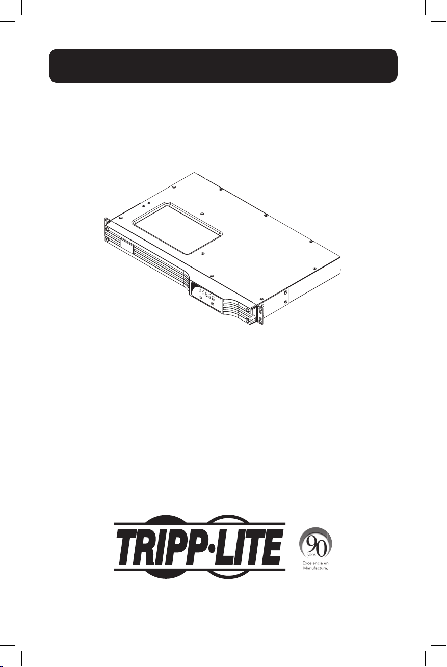
SmartPro® 1U Rackmount
Intelligent, Line-Interactive UPS System
SMX500RT1U
Series: AG-0098
Important Safety Instructions 2
Mounting 3
Quick Installation 4
Optional Installation 6
Basic Operation 7
Storage and Service 10
Battery Replacement 10
Product Registration 11
Español 12
Français 23
Pусский 34
PROTECT YOUR INVESTMENT!
Register your product for quicker service
and ultimate peace of mind.
You could also win an
ISOBAR6ULTRA surge protector—
a $50 value!
www.tripplite.com/warranty
1111 W. 35th Street, Chicago, IL 60609 USA • www.tripplite.com/support
Copyright ©2015 Tripp Lite. All rights reserved. SmartPro® is a registered trademark of Tripp Lite.
1
15-01-102-9332C7.indb 1 1/16/2015 10:38:44 AM
Page 2

Important Safety Instructions
SAVE THESE INSTRUCTIONS
This manual contains important instructions that should be followed during the installation, operation
and storage of all Tripp Lite UPS Systems. Failure to heed these warnings will void your warranty.
UPS Location Warnings
• Use caution when lifting your UPS. Because of the considerable weight of all rackmount UPS
systems, at least two people should assist in lifting and installing them.
• Install your UPS indoors, away from excess moisture or heat, dust or direct sunlight.
• For best performance, the ambient temperature near your UPS should be between 0° C and
40° C (between 32° F and 104° F).
• Leave adequate space around all sides of the UPS for proper ventilation. Do not obstruct its
vents or fan openings.
UPS Connection Warnings
• The UPS contains its own energy source (battery). The output terminals may be live even
when the UPS is not connected to an AC supply.
• Connect your UPS to a properly grounded AC power outlet. Do not modify the UPS’s plug in a
way that would eliminate the UPS’s connection to ground. Do not use adapters that eliminate
the UPS’s connection to ground.
• Do not plug your UPS into itself; this will damage the UPS and void your warranty.
• If you are connecting your UPS to a motor-powered AC generator, the generator must provide
filtered, frequency-regulated, computer-grade output.
Equipment Connection Warnings
• Do not use Tripp Lite UPS Systems for life support applications in which a malfunction or
failure of a Tripp Lite UPS System could cause failure or significantly alter the performance
of a life-support device.
• Do not connect surge suppressors or extension cords to the output of your UPS. This might
overload the UPS and will void the surge suppressor and UPS warranties.
Battery Warnings
• Batteries can present a risk of electrical shock and burn from high short-circuit current. Observe
proper precautions. Do not dispose of the batteries in a fire. Do not open the UPS or batteries.
Do not short or bridge the battery terminals with any object. Unplug and turn off the UPS before
performing battery replacement. Use tools with insulated handles. There are no user-serviceable
parts inside the UPS. Battery replacement should be performed only by authorized service
personnel using the same number and type of batteries (sealed Lead-Acid). The batteries are
recyclable. Refer to your local codes for disposal requirements or in the USA only call
1-800-SAV-LEAD or 1-800-8-BATTERY (1-800-8-228-8379) or visit www.call2recycle.org for
recycling information. Tripp Lite offers a complete line of UPS System Replacement Battery
Cartridges (R.B.C.). Visit Tripp Lite on the Web at www.tripplite.com to locate the specific
replacement battery for your UPS.
• During hot-swap battery replacement, the UPS will not provide backup power in the event of
a blackout or other power interruptions.
• Do not operate UPS without batteries.
• When adding external battery packs to select models with external battery pack connectors,
connect only Tripp Lite-recommended battery packs of the correct voltage and type. Do not
connect or disconnect battery packs when the UPS is operating on battery power.
2
15-01-102-9332C7.indb 2 1/16/2015 10:38:44 AM
Page 3
Mounting
Mount your equipment in either a 4-post or 2-post rack or rack enclosure. The user must
determine the fitness of hardware and procedures before mounting. If hardware and procedures
are not suitable for your application, contact the manufacturer of your rack or rack enclosure. The
procedures described in this manual are for common rack and rack enclosure types and may not
be appropriate for all applications.
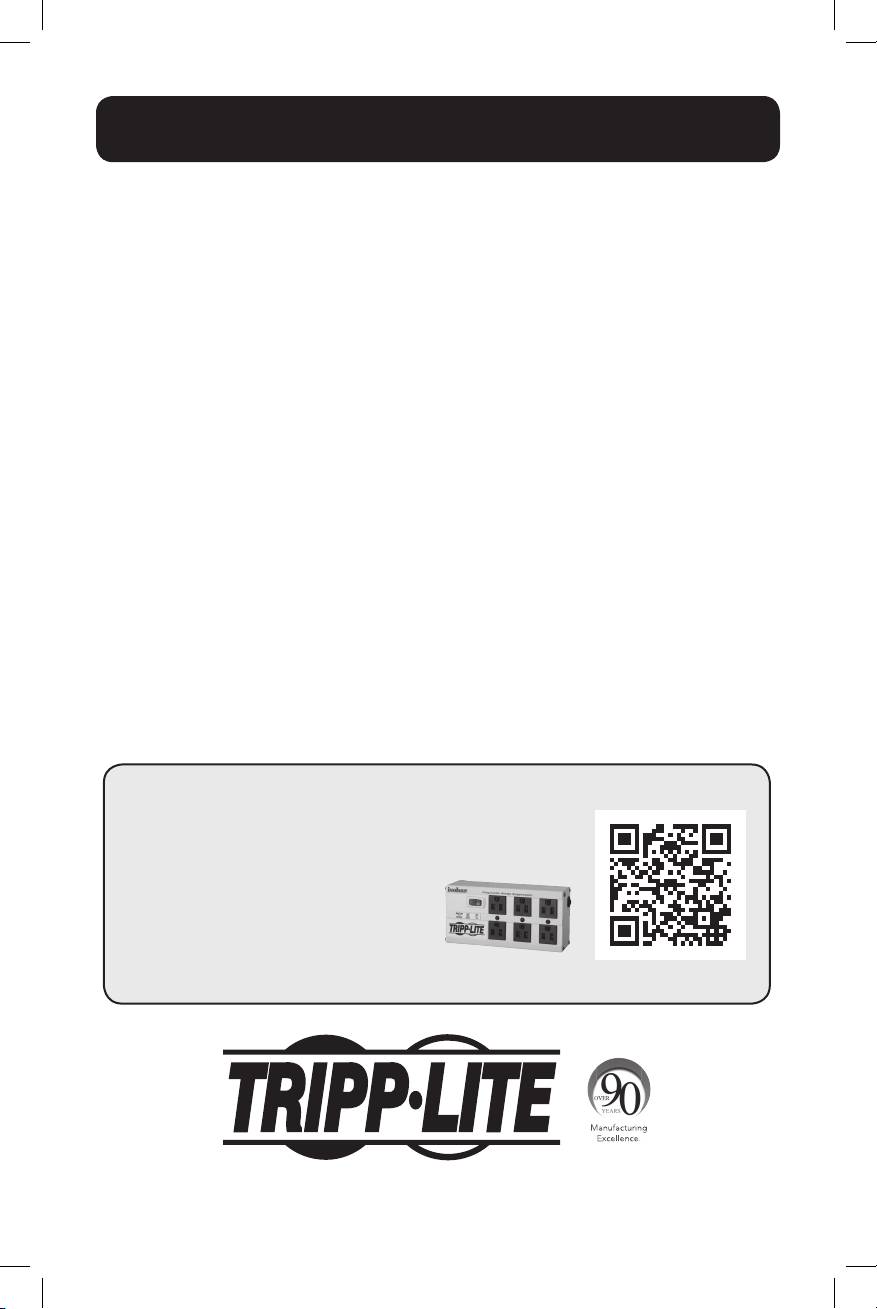
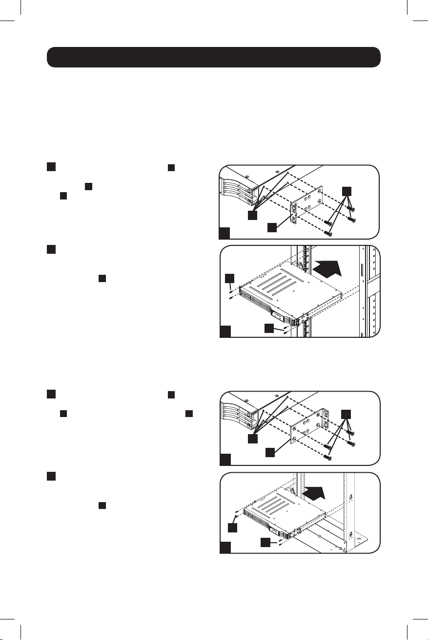
4-Post Rack Mounting
All UPS models include hardware required to mount in a 4-post rack.
1
Attach mounting ears
mounting holes of your equipment
the screws provided
face forward.
2
Using an assistant if necessary, lift your
equipment and mount it to the rack. Attach
it by screwing the appropriate hardware
through its mounting ears and into the rack
rails.
A
to the front
C
. The ears should
B
using
D
C
B
1
A
D
2
D
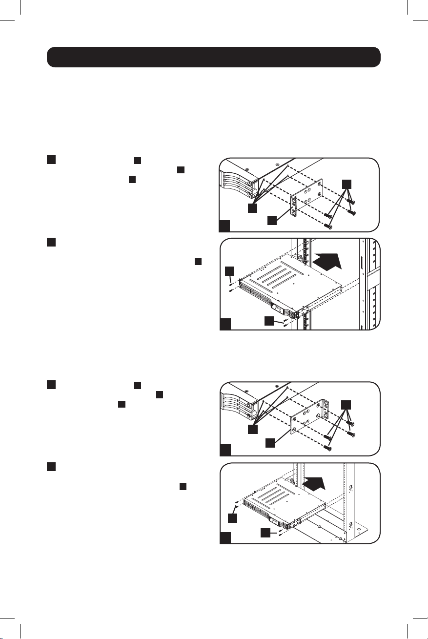
2-Post (Telecom) Rack Mounting
Following the procedures below, mount the 1U UPS model in 2-post racks with the included
hardware.
1
Attach mounting ears
mounting holes of your UPS
screws provided
backward.
2
Using an assistant if necessary, lift your UPS
and attach it to the rack by passing the
screws, nuts and washers provided
through its mounting ears and into the rack
rails.
A
to the front
B
using the
C
. The ears should face
C
B
1
D
A
D
2
3
D
15-01-102-9332C7.indb 3 1/16/2015 10:38:47 AM
Page 4
Mounting
Tower Mounting
Mount all UPS models in an upright, tower position using included hardware. The user must
determine the fitness of hardware and procedures before mounting.
Stand your UPS on its side with the LED/Control
panel at the top. Attach one rack mounting ear
A
to each side of the UPS using included
screws.
Quick Installation
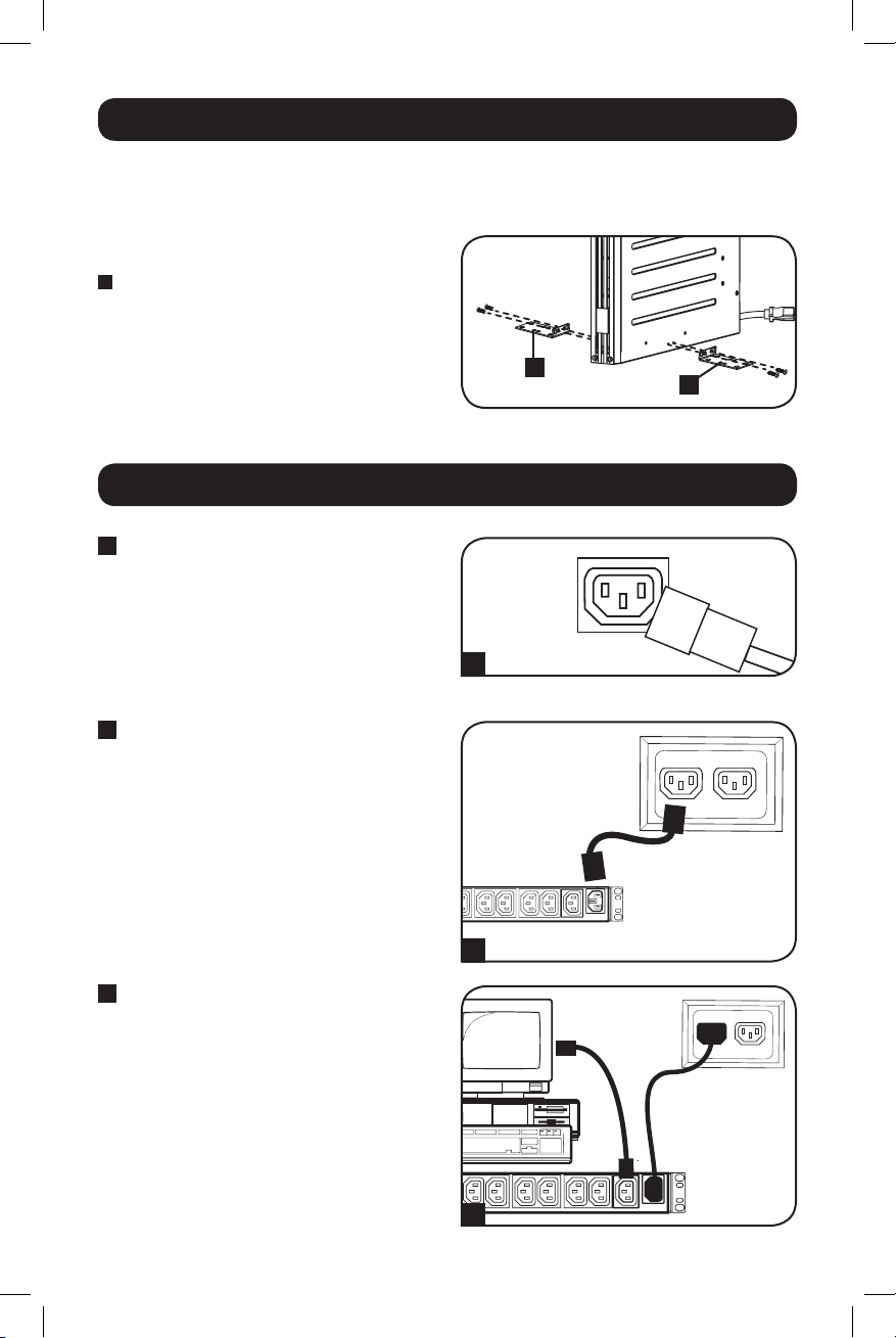
1
Unplug computer’s power cord
from both AC outlet and
computer’s AC input.
2
Insert the female plug of
computer’s cord into UPS’s AC
input. Insert the male plug of
computer’s cord into AC outlet.*
NOTE! after you plug the UPS into a live AC
outlet, the UPS (in “Standby” mode) will
automatically charge its batteries,** but will not
supply power to its outlets until it is turned ON
(see Step 3 below).
* See Specifications for circuit amperage
requirements. ** The BATTERY CHARGE LED will
be the only LED illuminated.
3
Find one of the power cords
that came with the UPS. Insert
the cord’s female plug into
computer’s AC input. Insert the
cord’s male plug into any of
UPS’s female output
receptacles.
A
A
1
IEC320-C14 plug shown
2
3
4
15-01-102-9332C7.indb 4 1/16/2015 10:38:49 AM
Page 5
Quick Installation
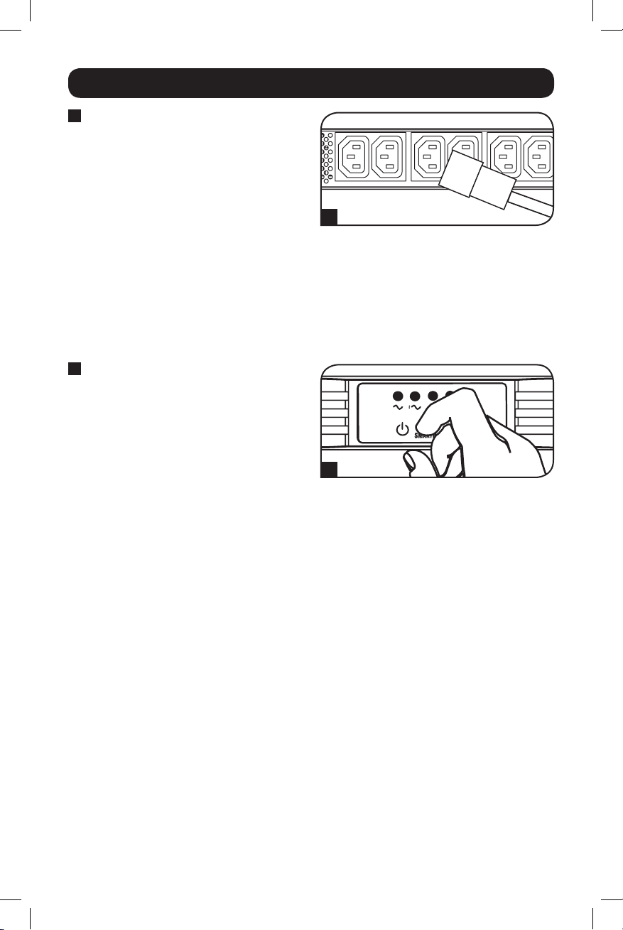
4
Plug your equipment into the
UPS.*
Plug your equipment into the UPS. Repeat
step 3 above using the additional power
cord(s) that came with the UPS.
Note: Additional interconnection cords (C13 to C14)
are available from Tripp Lite. Call 773.869.1234
(Part # P004-006).
* Your UPS is designed to support only computer
equipment. You will overload the UPS if the total VA
ratings for all the equipment you connect exceeds
the UPS’s Output Capacity (see Specifications). To
find your equipment’s VA ratings, look on their
nameplates. If the equipment is listed in amps,
multiply the number of amps by 230 to determine
VA. (Example: 1 amp × 230 = 230 VA). If you are
unsure if you have overloaded the UPS’s outlets,
see “OUTPUT LOAD LEVEL” LED description.
5
Turn the UPS ON.
Press and hold the “ON/OFF/STANDBY”
button for one second. The alarm will beep
once briefly after one second has passed.
Release the button.
4
5
5
15-01-102-9332C7.indb 5 1/16/2015 10:38:51 AM
Page 6
Optional Installation
4-5
These connections are optional. Your UPS will function properly without these connections.
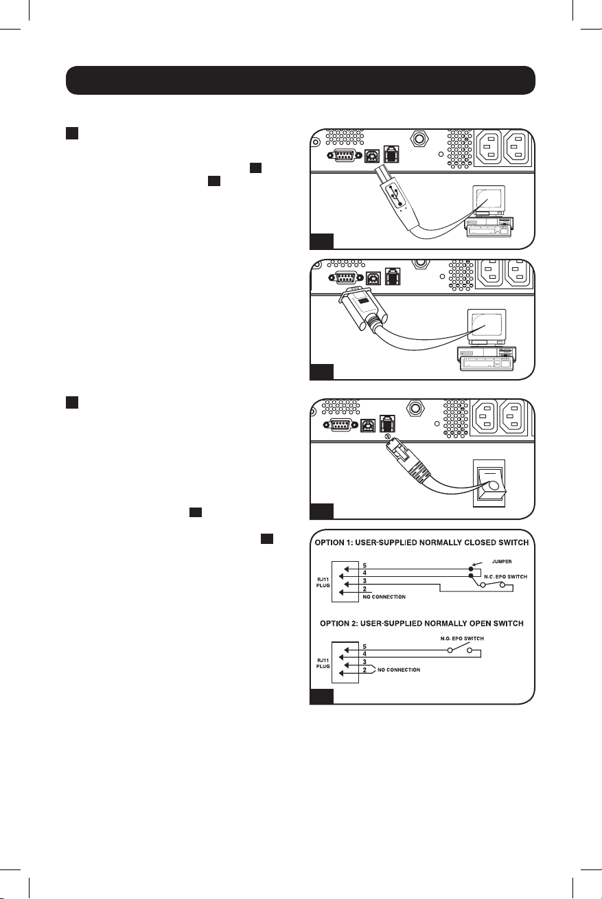
1
USB and RS-232 Serial
Communications
1A
Use the included USB cable (see
or DB9 serial cable (see
1B
) to connect the
communication port on your computer to
the communication port of your UPS. Install
on your computer the Tripp Lite PowerAlert
Software appropriate to your computer’s
operating system. Your UPS may feature
additional communications ports; these
ports may also be connected to additional
computers which have PowerAlert Software
installed. Consult your PowerAlert manual
for more information.
2
EPO Port Connection
This optional feature is only for those
applications which require connection to a
facility’s Emergency Power Off (EPO) circuit.
When the UPS is connected to this circuit, it
enables emergency shutdown of the UPS’s
inverter.
Using the cable provided, connect the EPO
2A
port of your UPS (see
) to a user-supplied
normally closed or normally open switch
according to the circuit diagram (see
Note: The EPO port is not a phone line surge
suppressor; do not connect a phone line to this
port.
) and/
2B
).
1A
1B
2A
2B
6
15-01-102-9332C7.indb 6 1/16/2015 10:38:51 AM
Page 7
Basic Operation
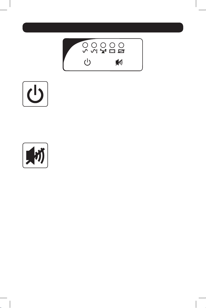
LED Interface
Buttons (Front Panel)
“ON/OFF/STANDBY” Button
• To turn the UPS ON: With the UPS plugged into a live AC wall outlet*, press
and hold the “ON/OFF/STANDBY” button for one second.** Release the button.
If utility power is absent, you can “cold-start” the UPS (i.e.: turn it ON and
supply power for a limited time from its batteries***) by pressing and holding
the “ON/OFF/STANDBY” button for one second.**
• To turn the UPS OFF: With the UPS ON and receiving utility power, press and
hold the “ON/OFF/STANDBY” button for one second.** Then unplug the UPS
from the wall outlet. The UPS will be completely OFF.
* After you plug the UPS into a live AC outlet, the UPS (in “Standby” mode) will automatically
charge its batteries, but will not supply power to its outlets until it is turned ON. ** The alarm
will beep once briefly after the indicated interval has passed. *** If fully charged.
“MUTE/TEST” Button
To Silence (or “Mute”) UPS Alarms: Briefly press and release the “MUTE/TEST”
button.
To Run a Self-Test: With your UPS plugged in and turned ON, press and hold the
“MUTE/TEST” button for two seconds.* Continue holding the button until the
alarm beeps several times and the UPS performs a self-test. See “Results of a
Self-Test” below.
Note: You can leave connected equipment on during a self-test. Your UPS, however, will not
perform a self-test if the UPS is not turned on (see “ON/OFF/STANDBY” Button description).
CAUTION! Do not unplug your UPS to test its batteries. This will remove
safe electrical grounding and may introduce a damaging surge into your
network connections.
* The alarm will beep once briefly after the indicated interval has passed.
Results of a Self-Test: the test will last approximately 10 seconds as the UPS
switches to battery to test its load capacity and battery charge.
• If the “OUTPUT LOAD LEVEL” LED remains lit red and the alarm continues to
sound after the test, the UPS’s outlets are overloaded. To clear the overload,
unplug some of your equipment and run the self-test repeatedly until the
“OUTPUT LOAD LEVEL” LED is no longer lit red and the alarm is no longer
sounding.
CAUTION! Any overload that is not corrected by the user immediately
following a self-test may cause the UPS to shut down and cease
supplying output power in the event of a blackout or brownout.
• If the “BATTERY WARNING” LED remains lit and the alarm continues to
sound after the test, the UPS batteries need to be recharged or replaced.
Allow the UPS to recharge continuously for 12 hours, and repeat the selftest. If the LED remains lit, contact Tripp Lite for service. If your UPS requires
battery replacement, visit www.tripplite.com to locate the specific Tripp Lite
replacement battery for your UPS.
7
15-01-102-9332C7.indb 7 1/16/2015 10:38:51 AM
Page 8
Basic Operation
Indicator Lights (Front Panel)
All Indicator Light descriptions apply when the UPS is plugged into a wall outlet and turned ON.
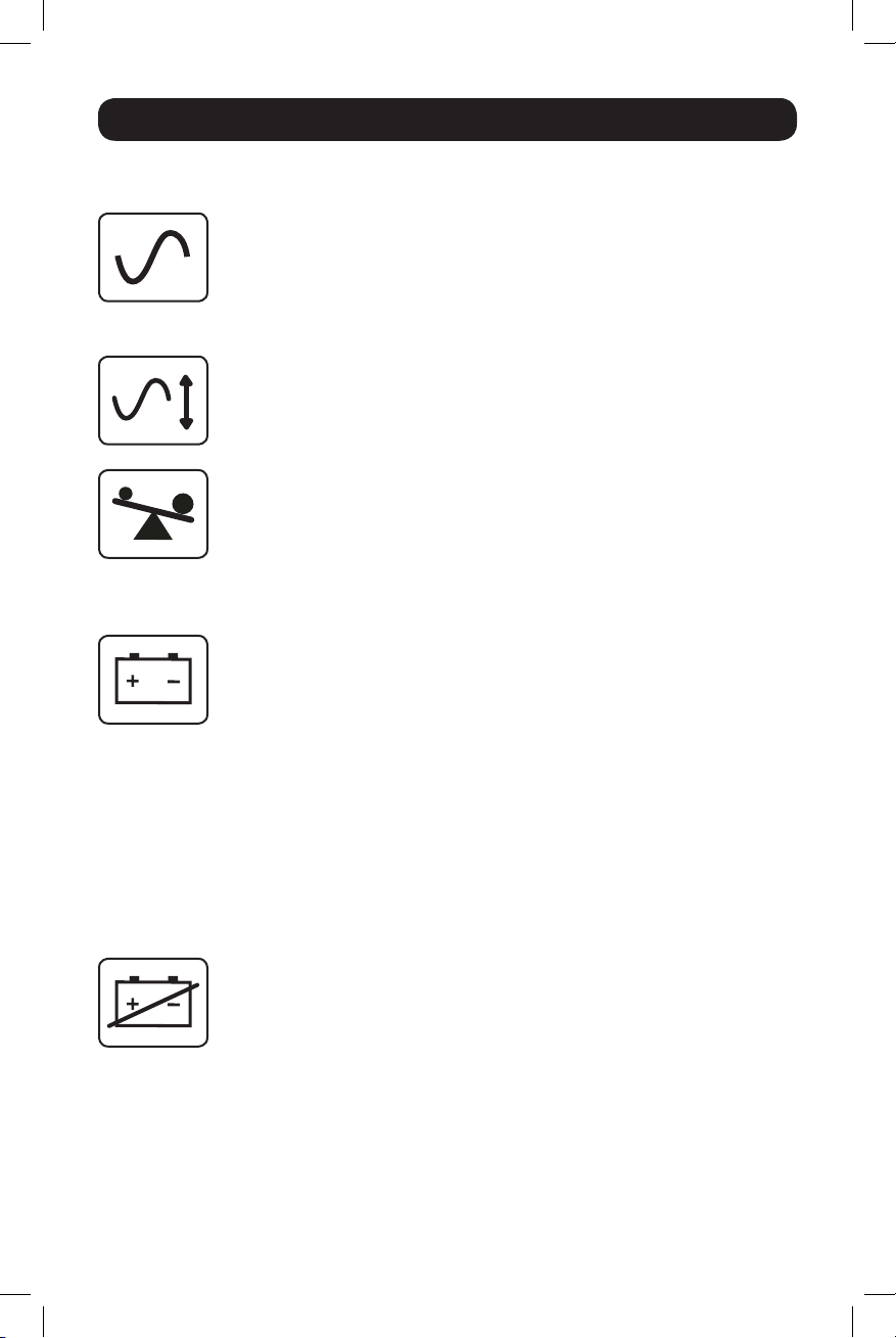
“POWER” LED: This green LED lights continuously when the UPS is ON and
supplying connected equipment with AC power from a utility source. The LED
flashes and an alarm sounds (4 short beeps followed by a pause) to indicate the
UPS is operating from its internal batteries during a blackout or severe brownout.
If the blackout or severe brownout is prolonged, you should save files and shut
down your equipment since internal battery power will eventually be depleted.
See “BATTERY CHARGE” LED description below.
“VOLTAGE CORRECTION” LED: This green LED lights continuously whenever the
UPS is automatically correcting high or low AC voltage on the utility line without
the assistance of battery power. The UPS will also emit a slight clicking noise.
These are normal, automatic operations of the UPS; no action is required on your
part.
“OUTPUT LOAD LEVEL” LED: This multicolored LED indicates the approximate
electrical load of equipment connected to the UPS’s AC outlets. It will turn from
green (light load) to yellow (medium load) to red (overload). If the LED is red
(either illuminated continuously or flashing), clear the overload immediately by
unplugging some of your equipment from the outlets until the LED changes from
red to yellow (or green). CAUTION! Any overload that is not corrected by the user
immediately may cause the UPS to shut down and cease supplying output power
in the event of a blackout or brownout.
“BATTERY CHARGE” LED: When the UPS is operating from utility power, this LED
indicates the approximate charge state of the UPS’s internal batteries: red
indicates the batteries are beginning to charge; yellow indicates the batteries are
roughly midway through charging; and green indicates the batteries are fully
charged. When the UPS is operating from battery power during a blackout or
severe brownout, this LED indicates the approximate amount of energy
(ultimately affecting runtime) which the UPS’s batteries will provide: red indicates
a low level of energy; yellow indicates a medium level of energy; and green
indicates a high level of energy. Since the runtime performance of all UPS
batteries will gradually deplete over time, it is recommended that you periodically
perform a self-test (see “MUTE/TEST” Button description) to determine the energy
level of your UPS batteries BEFORE a blackout or severe brownout occurs. During
a prolonged blackout or severe brownout, you should save files and shut down
your equipment since battery power will eventually be depleted. When the LED
turns red and an alarm sounds continuously, it indicates the UPS’s batteries are
nearly out of power and UPS shut down is imminent.
“BATTERY WARNING” LED: This LED lights red and an alarm sounds
intermittently after you complete a self-test (See “MUTE/TEST” Button
description) to indicate the UPS batteries need to be recharged or replaced.
Allow the UPS to recharge continuously for 12 hours, and repeat the self-test. If
the LED continues to light, contact Tripp Lite for service. If your UPS requires
battery replacement, visit www.tripplite.com to locate the specific Tripp Lite
replacement battery for your UPS.
8
15-01-102-9332C7.indb 8 1/16/2015 10:38:51 AM
Page 9
Basic Operation
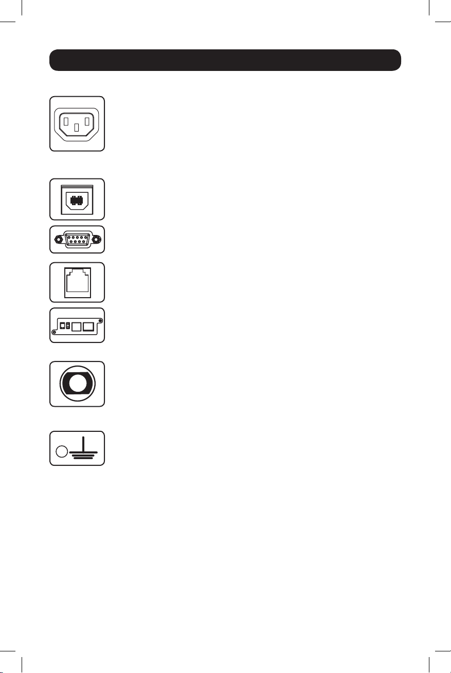
Other UPS Features (Rear Panel)
AC Receptacles: Your UPS features IEC320-C13 outlets. These outlets provide
your connected equipment with AC line power during normal operation and
battery power during blackouts and brownouts. The UPS protects equipment
connected to these receptacles against damaging surges and line noise. If you
have a serial or USB connection to your UPS, you can remotely reboot connected
IEC320-C13/230V
equipment by turning receptacles OFF and ON using Tripp Lite’s PowerAlert
software. Models also feature outlets labeled “UNSWITCHED” which may not be
remotely turned off.
Communications Ports (USB or RS-232): These ports connect your UPS to
any workstation or server. Use with Tripp Lite’s PowerAlert Software and included
cables to enable your computer to automatically save open files and shut down
equipment during a blackout. Also use PowerAlert Software to monitor a wide
variety of AC line power and UPS operating conditions. Consult your PowerAlert
Software manual or contact Tripp Lite Customer Support for more information.
See “USB and RS-232 Serial Communications” in the “Optional Installation”
section for installation instructions.
EPO (Emergency Power Off) Port: Your UPS features an EPO port that may be
used to connect the UPS to a contact closure switch to enable emergency
inverter shutdown. See Optional Installation section.
Accessory Slot: Remove the small cover panel from this slot to install optional
accessories to remotely monitor and control your UPS. Refer to your
accessory’s manual for installation instructions. Contact Tripp Lite at
www.tripplite.com/support for more information, including a list of available
SNMP, network management and connectivity products.
Input Breaker: Protect your electrical circuit from overcurrent draw from the UPS
load. If these breakers trip, remove some of the load; then reset them by
pressing the breaker(s) in.
Output Breaker: Protect your UPS from output overload. If one or more breakers
trip, remove some of the load on the circuit(s), then reset them by pressing the
breaker switch(es) in.
Ground Screw: Use this to connect any equipment that requires a chassis
ground.
9
15-01-102-9332C7.indb 9 1/16/2015 10:38:51 AM
Page 10
Storage and Service
Storage
Before storing your UPS, turn it completely OFF: With the UPS ON and receiving utility power, press
and hold the “ON/OFF/STANDBY” button for one second (an alarm will beep once briefly after the
interval has passed); then, unplug the UPS from the wall outlet. If you store your UPS for an
extended period of time, recharge the UPS batteries once every three months: plug the UPS into a
wall outlet; allow it to charge for 12 hours; and then unplug it and place it back in storage. Note:
after you plug the UPS in, it will automatically begin charging its batteries; however, it will not
supply power to its outlets (see Quick Installation section). If you leave your UPS batteries
discharged for an extended period of time, they will suffer a permanent loss of capacity.
Service
Before returning your UPS for service, follow these steps:
1. Review the installation and operation instructions in this manual to ensure that the service
problem does not originate from a misreading of the instructions. Also, check that the UPS
System’s circuit breaker(s) are not tripped. This is the most common cause of service inquiries
which can be easily remedied by following the resetting instructions in this manual.
2. If the problem continues, do not contact or return the UPS to the dealer. Instead, contact
Tripp Lite at www.tripplite.com/support. A service technician will ask for the UPS’s model
number, serial number and purchase date.
3. If the problem requires service, the technician will issue you a Returned Material Authorization
(RMA) number, which is required for service. If you require packaging, the technician can
arrange to send you proper packaging. Securely pack the UPS to avoid damage during shipping.
Do not use Styrofoam beads for packaging. Any damages (direct, indirect, special, incidental or
consequential) to the UPS incurred during shipment to Tripp Lite or an authorized Tripp Lite
service center is not covered under warranty. UPS Systems shipped to Tripp Lite or an authorized
Tripp Lite service center must have transportation charges prepaid. Mark the RMA number on
the outside of the package. If the UPS System is within the 2-year warranty period, enclose a
copy of your sales receipt. Return the UPS for service using an insured carrier to the address
given to you by the Tripp Lite service technician.
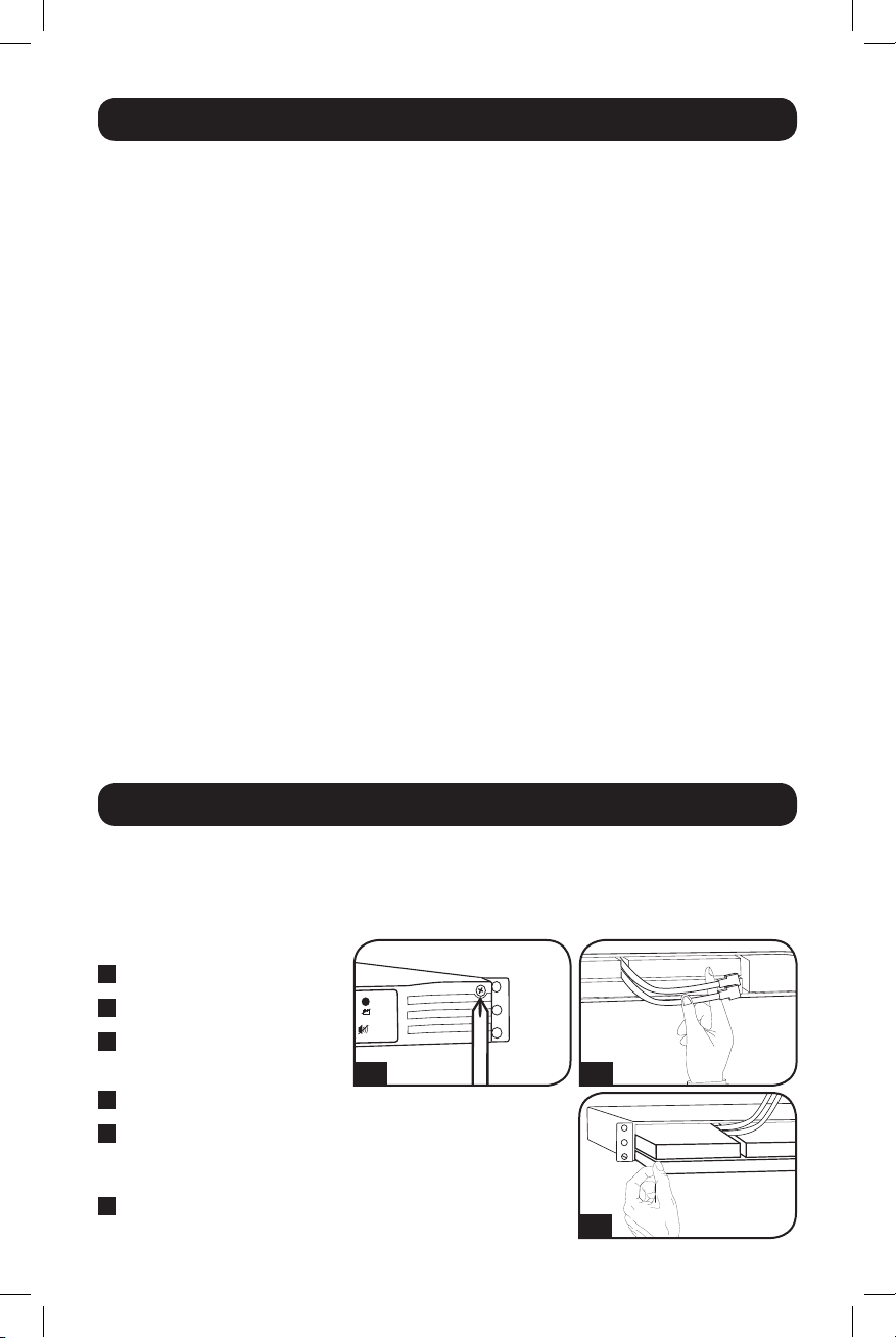
Battery Replacement
Under normal conditions, the original batteries in your UPS will last many years. See Safety section
before replacing batteries. The batteries are designed for hot-swap replacement (i.e. leaving the
UPS in ON mode), but qualified service personnel may wish to put the UPS in the OFF mode before
proceeding.
Procedure
1
Remove Front Panel
2
Disconnect Batteries
3
Remove/Dispose of
Batteries
4
Add Batteries
5
Connect Batteries
Attach connectors: black-toblack and red-to-red.
6
Replace Front Panel
15-01-102-9332C7.indb 10 1/16/2015 10:38:52 AM
1/6
10
2/5
3/4
Page 11

Product Registration
Visit www.tripplite.com/warranty today to register your new Tripp Lite product. You’ll be automatically entered into
a drawing for a chance to win a FREE Tripp Lite product!*
* No purchase necessary. Void where prohibited. Some restrictions apply. See Web site for details.
FCC RADIO/TV INTERFERENCE NOTICE: (FOR CLASS A MODELS)
Note: This equipment has been tested and found to comply with the limits for a Class A digital device, pursuant to Part 15 of the
FCC Rules. These limits are designed to provide reasonable protection against harmful interference when operated in a commercial
environment. This equipment generates, uses and can radiate radio frequency energy, and if not installed and used in accordance
with the instruction manual, may cause interference to radio communications. Operation of this equipment is likely to cause
harmful interference in which case the user will be required to correct the interference at his own expense. The user must use
shielded cables and connectors with this product. Any changes or modifications to this product not expressly approved by the party
responsible for compliance could void the user’s authority to operate the equipment.
FCC RADIO/TV INTERFERENCE NOTICE: (FOR CLASS B MODELS)
Note: This equipment has been tested and found to comply with the limits for a Class B digital device, pursuant to Part 15 of the
FCC Rules. These limits are designed to provide reasonable protection against harmful interference in a residential installation. This
equipment generates, uses and can radiate radio frequency energy, and if not installed and used in accordance with the instruction
manual, may cause interference to radio communications. However, there is no guarantee that interference will not occur in a
particular installation. If this equipment does cause harmful interference to radio or television reception, which can be determined
by turning the equipment off and on, the user is encouraged to try to correct the interference using one or more of the following
measures: reorient or relocate the receiving antenna; increase the separation between the equipment and the receiver; connect the
equipment into an outlet on a circuit different from that which the receiver is connected; consult the dealer or an experienced radio/
television technician for help. The user must use shielded cables and connectors with this product. Any changes or modifications to
this product not expressly approved by the party responsible for compliance could void the user’s authority to operate the
equipment. This device complies with part 15 of the FCC rules. Operation is subject to the following 2 conditions: (1) This device
may not cause harmful interference, and (2) This device must accept any interference received, including interference that may
cause undesired operation.
Regulatory Compliance Identification Numbers
For the purpose of regulatory compliance certifications and identification, your Tripp Lite product has been assigned a unique series
number. The series number can be found on the product nameplate label, along with all required approval markings and
information. When requesting compliance information for this product, always refer to the series number. The series number should
not be confused with the marketing name or model number of the product.
Tripp Lite has a policy of continuous improvement. Product specifications are subject to change without notice.
Note on Labeling
Two symbols are used on the label.
V~ : AC Voltage
: DC Voltage
V
1111 W. 35th Street, Chicago, IL 60609 USA • www.tripplite.com/support
11
15-01-102-9332C7.indb 11 1/16/2015 10:38:52 AM
Page 12
Manual del propietario
SmartPro® 1U Rackmount
Sistemas de UPS Inteligentes e Interactivos en Línea
SMX500RT1U
Serie: AG-0098
Instrucciones de seguridad importantes 13
Montaje 14
Instalación rápida 15
Instalación opcional 16
Operación básica 17
Almacenamiento y servicio 21
Reemplazo de batería 22
English 1
Français 23
Pусский 34
MÁS DE
1111 W. 35th Street, Chicago, IL 60609 USA • www.tripplite.com/support
Copyright ©2015 Tripp Lite. Todos los derechos reservados.
SmartPro® es una marca comercial registrada de Tripp Lite.
12
15-01-102-9332C7.indb 12 1/16/2015 10:38:57 AM
Page 13

Instrucciones de seguridad importantes
GUARDE ESTAS INSTRUCCIONES
Este manual contiene importantes instrucciones que deben seguirse durante la instalación,
operación y el almacenamiento de todos los UPS de Tripp Lite. La no observancia de estas
advertencias anulará su garantía.
Advertencias sobre la ubicación del UPS
• Tenga cuidado al levantar el UPS. Debido al gran peso de los UPS para montaje en bastidor,
se requieren por lo menos dos personas para que le ayuden a levantarlos e instalarlos.
• Instale su UPS bajo techo, lejos de la humedad, el calor, el polvo o la luz solar directa.
• Para un mejor funcionamiento, la temperatura ambiente cerca de su UPS debe estar entre 0° C
y 40° C (32° F - 104° F)
• Deje una cantidad adecuada de espacio alrededor de todos los lados del UPS para sua
adecuada ventilación. No obstruya sus respiraderos ni las aberturas de ventilación.
Advertencias sobre la conexión del UPS
• El UPS contiene su propia fuente de energía (batería). Los terminales de salida pueden estar
con energía incluso cuando el UPS no está conectado a un suministro de corriente alterna.
• Conecte su UPS a una toma de CA puesta a tierra apropiadamente. No modifique el enchufe
del UPS en ninguna forma que elimine su conexión a tierra. No use adaptadores que eliminen la
conexión del UPS a tierra.
• No conecte el UPS a si mismo ya que podría dañarse y anular la garantía.
• Si va a conectar su UPS a un generador de corriente alterna accionado por un motor, el
generador debe suministrar una salida filtrada, con regulación por frecuencia grado computadora.
Advertencias sobre la conexión de equipos
• No utilice sistemas UPS de Tripp Lite para aplicaciones de soporte de vida en las que un
funcionamiento defectuoso o una falla del UPS pudiera causar un mal funcionamiento o una
alteración importante en el funcionamiento de un dispositivo de soporte de vida.
• No conecte supresores de sobretensiones ni cordones de extensión a la salida de su UPS. Esto
puede sobrecargarlo y anular su garantía y la del supresor de sobretensiones.
Advertencias sobre la batería
• Las baterías presentan un peligro de choque eléctrico y quemaduras debido a las altas
corrientes de cortocircuito. Observe las precauciones apropiadas. No deseche las baterías en un
incinerador. No abra el UPS ni las baterías. No ponga los terminales de la batería en corto o en
puente con ningún objeto. Apague y desconecte el UPS antes de reemplazar la batería. Use
herramientas con mangos aislados. No hay piezas que el usuario pueda reparar dentro del UPS.
El reemplazo de baterías debe ser realizado solamente por personal de servicio autorizado
usando el mismo número y tipo de baterías (plomo-ácido, selladas). Las baterías son
reciclables. Consulte la reglamentación local para los requisitos de disposición de desechos; en
los EE.UU. llame al 1-800-SAV-LEAD o al 1-800-8-BATTERY (1-800-8-228-8379) o visite
www.call2recycle.org para obtener información sobre el proceso de reciclaje. Tripp Lite ofrece
una línea completa de cartuchos de reemplazo de batería para UPS (R.B.C.) Visite la página
web de Tripp Lite en www.tripplite.com para localizar la batería de reemplazo específica para su
UPS.
• Durante el reemplazo de baterías en operación (hot-swap), el UPS no proporcionará energía de
respaldo en el caso de una falla del servicio eléctrico u otras interrupciones de energía.
• No opere el UPS sin baterías.
• Al agregar bancos de baterías externas a modelos exclusivos con conectores para este tipo de
bancos, sólo emplee bancos recomendados por Tripp Lite del voltaje y tipo correctos. No
conecte ni desconecte bancos de baterías cuando el UPS esté funcionando con energía de las
baterías.
13
15-01-102-9332C7.indb 13 1/16/2015 10:38:57 AM
Page 14
Montaje
Monte su equipo en un bastidor de 2 o 4 postes. El usuario debe determinar la idoneidad de los
materiales y accesorios, así como de los procedimientos antes del montaje. Si los materiales y
procedimientos no son adecuados para su aplicación, contacte con el fabricante de su bastidor.
Los procedimientos descritos en este manual son para bastidores comunes y de tipo caja y
podrían no ser apropiados para todas las aplicaciones.
Montaje de 4 postes
Todos los modelos de UPS incluyen los accesorios requeridos para montar un bastidor de 4 postes.
1
Instale las orejas de instalación A en los
orificios frontales de instalación de su
equipo B usando los tornillos suministrados
C
. Las orejas deben apuntar al frente.
2
Usando un ayudante si fuera necesario,
levante su equipo e instálelo en el rack.
Sujételo atornillando los accesorios
adecuados
instalación y en los rieles del rack.
D
a través de sus orejas de
B
1
A
D
C
2
D
Instalación en 2 Postes (Telecom)
Instale los modelos de UPS de 1U en racks de 2 postes con los accesorios incluidos siguiendo el
procedimiento descrito a continuación.
1
Instale las orejas de instalación
orificios frontales de instalación de su equipo
B
usando los tornillos suministrados
orejas deben apuntar hacia atrás.
2
Usando un ayudante si fuera necesario,
levante su equipo e instálelo en el rack.
Sujételo atornillando los accesorios
adecuados
instalación y en los rieles del rack.
D
a través de sus orejas de
A
en los
C
. Las
14
C
B
1
A
D
2
D
15-01-102-9332C7.indb 14 1/16/2015 10:38:58 AM
Page 15

Montaje
Montaje (En torre)
Monte todos los modelos de UPS en una posición vertical, de torre, usando los accesorios
incluidos. El usuario debe determinar la idoneidad de los materiales y accesorios así como de los
procedimientos antes del montaje.
Coloque su UPS sobre la parte lateral y con el
panel LED/de control en la parte superior. Fije
una oreja de montaje
lado del UPS usando los tornillos.
A
del bastidor a cada
A
A
Instalación rápida
1
Desenchufe el cable eléctrico
del ordenador del enchufe de
toma eléctrica C.A. y de la
entrada C.A. del ordenador.
1
IEC320-C14 enchufe demostrado
2
Inserte el enchufe hembra del
cable del ordenador en el
dispositivo de entrada C.A. del
UPS. Inserte el enchufe macho
del cable eléctrico del
ordenador en el enchufe de
toma eléctrica C.A.*
NOTA Después de conectar el UPS en una toma
de corriente alterna con energía, el equipo (en
modo “Standby”) cargará automáticamente sus
baterías,** pero no suministrará energía a sus
salidas hasta que sea encendido (vea más abajo
el Paso 15)
*Vea las especificaciones técnicas sobre los
requerimientos de amperaje para circuito. **El
único diodo o indicador iluminado será el de
recargo de batería.
3
Busque uno de los cables
eléctricos que vienen con el
UPS. Inserte el enchufe hembra
en la toma eléctrica de entrada
C.A. del ordenador. Inserte el
enchufe macho en cualquiera
de los receptáculos de salida
del UPS.
2
3
15
15-01-102-9332C7.indb 15 1/16/2015 10:38:58 AM
Page 16

Instalación rápida
4
Enchufe su equipo en el UPS.*
Repita el procedimiento 3 mencionado arriba
usando los demás cables eléctricos que se
adjuntaron con el UPS.
Nota: Se pueden obtener cables de interconexión
adicionales (C13 a C14) través de Tripp Lite. Llame
al +1.773.869.1234 (Repuesto # P004-006).
*Su UPS ha sido diseñado para apoyar su equipo
de ordenadores solamente. Usted sobrecargará el
UPS si el total del índice de los voltios/ amperios
para todo el equipo excede la capacidad de salida
del UPS (ver especificaciones). Para averiguar el
índice de voltios/amperios de su equipo, búsquelos
en la placa del fabricante.Si el equipo está
enumerado en amperios, multiplique el número de
amperios por 230 para determinar los voltios/
amperios (Por ejemplo: 1 amp x 230 = 230 voltios/
amperios). Si no está seguro de haber
sobrecargado las tomas eléctricas del UPS, vea la
descripción sobre el indicador “NIVEL DE
SOBRECARGA DE SALIDA”.
5
Encienda el UPS.
Presione y mantenga presionado el botón
“ON/OFF/STANDBY” (Encendido/Apagado/
Reserva) durante un segundo. La alarma
emitirá un pitido brevemente después de
pasado un segundo. Suelte el botón.
4
5
Instalación opcional
Estas conexiones son opcionales. Su UPS funcionará correctamente sin ellas.
1
Comunicaciones USB y serie
RS-232 (todos los modelos)
Use el cable USB incluido (vea
cable serie DB9 (vea 1B) para conectar el
puerto de comunicaciones de su
computadora al puerto de comunicaciones
de su UPS. Instale en su computadora el
software PowerAlert de Tripp Lite apropiado
para su sistema operativo. Su UPS puede
tener puertos adicionales de
comunicaciones; estos puertos también
pueden estar conectados a computadoras
adicionales con el software PowerAlert
instalado. Consulte su manual de PowerAlert
para mayor información.
15-01-102-9332C7.indb 16 1/16/2015 10:38:58 AM
1A
) y/o el
1A
1B
16
Page 17

4-5
OPCIÓN 1: INTERRUPTOR NORMALMENTE CERRADO
PROPORCIONADO POR EL USUARIO
OPCIÓN 2: PROPORCIONADO POR EL USUARIO
NORMALMENTE ABIERTO DEL INTERRUPTOR
INTERRUPTOR
EPO
INTERRUPTOR EPO
SALTADOR
SIN CONEXIÓN
SIN CONEXIÓN
Instalación opcional
2
Conexión de puerto EPO
Esta característica opcional es sólo para
aquellas aplicaciones que requieran una
conexión al circuito de desconexión de
emergencia (EPO) de la instalación Cuando
el UPS está conectado a este circuito,
permite el apagado de emergencia del
inversor del UPS.
Usando el cable suministrado, conecte el
puerto EPO de su UPS (vea 2A) a un
contacto normalmente cerrado o
normalmente abierto suministrado por el
usuario, de acuerdo con el diagrama del
circuito (vea
2B
).
Nota: El puerto EPO no es un supresor de
sobretensiones de línea telefónica; no conecte una
línea telefónica en este puerto.
Operación básica
2A
2B
Interfaz LED
Botones (Panel frontal)
Botón “ON/OFF/STANDBY” (Encendido/Apagado/Reserva)
• Para encender el UPS: Con el UPS conectado en una toma de CA con
energía*, presione y mantenga presionado el botón “ON/OFF/STANDBY”
(Encendido/Apagado/Reserva) por un segundo.** Suelte el botón. Si no hay
energía de la red, puede “arrancar en frío”el UPS (es decir, encenderlo y
suministrar energía de sus baterías por un tiempo limitado***) presionando y
manteniendo presionado el botón “ON/OFF/STANDBY” (Encendido/Apagado/
Reserva) durante un segundo.**
15-01-102-9332C7.indb 17 1/16/2015 10:38:59 AM
• Para apagar el UPS: Con el UPS encendido y recibiendo energía de la red,
presione y mantenga presionado el botón “ON/OFF/STANDBY” (Encendido/
Apagado/Reserva) durante un segundo.** Luego desconecte el UPS de la
toma de corriente. El UPS se apagará.
* Después de conectar el UPS en una toma de CA con energía, el equipo (en modo
“Standby”) cargará automáticamente sus baterías, pero no suministrará energía a sus
salidas hasta que sea encendido. ** La alarma emitirá un pitido brevemente después de
pasado el intervalo indicado. *** Si está completamente cargada..
17
Page 18

Operación básica
Botón “MUTE/TEST” (SILENCIO/PRUEBA)
Para silenciar las alarmas UPS: Presione brevemente el botón MUTE/TEST
(SILENCIO/PRUEBA) y luego suéltelo.
Para ejecutar una auto-prueba: Con su UPS conectado y encendido, presione
y mantenga presionado el botón MUTE/TEST (Silencio/Prueba) por dos
segundos.*Siga presionando el botón hasta que la alarma suene varias veces y
el UPS realice una auto-prueba. Vea “Resultados de una auto-prueba” más
abajo.
Nota: Puede dejar equipos conectados durante una auto-prueba. Sin embargo, el UPS, no
realizará una auto-prueba si no está encendido (vea la descripción del Botón “ON/OFF/
STANDBY”).
¡PRECAUCIÓN! No desconecte su UPS para probar sus baterías. Esto
eliminaría la conexión de seguridad a tierra y podría introducir una
sobretensión dañina en sus conexiones de red.
* La alarma emitirá un pitido brevemente después de pasado el intervalo indicado.
Resultados de una auto-prueba: La prueba durará cerca de 10 segundos
mientras el UPS conmuta a batería para probar su capacidad de carga y la
recarga de la batería.
• Si el LED “OUTPUT LOAD LEVEL” (NIVEL DE CARGA DE SALIDA) permanece
encendido rojo y la alarma continúa sonando después de la prueba, las
salidas del UPS están sobrecargadas. Para eliminar la sobrecarga,
desconecte algo de su equipo y ejecute la auto-prueba repetidamente
hasta que el LED ya no esté encendido rojo y la alarma ya no esté
sonando.
¡PRECAUCIÓN! Cualquier sobrecarga que no sea corregida por el
usuario inmediatamente después de una auto-prueba puede causar que
el UPS se apague y deje de suministrar energía de salida en el caso de
una falla del servicio eléctrico o una baja de voltaje.
• Si el LED “BATTERY WARNING” (ADVERTENCIA DE BATERÍA) sigue
encendido y la alarma continúa sonando después de la prueba, las baterías
del UPS deben recargarse o reemplazarse. Permita que el UPS se recargue
continuamente por 12 horas y repita la auto-prueba. Si el LED permanece
encendido, contacte con Tripp Lite para obtener servicio. Si su UPS requiere
el reemplazo de su batería, visite www.tripplite.com para localizar la batería
de reemplazo Tripp Lite específica para su UPS.
18
15-01-102-9332C7.indb 18 1/16/2015 10:38:59 AM
Page 19

Operación básica
Luces indicadoras (Panel frontal)
Todas las descripciones de luces indicadoras se aplican cuando el UPS está conectado en un
tomacorriente y encendido.
LED “POWER” (ALIMENTACIÓN): Este LED verde se enciende permanentemente
cuando el UPS está encendido y proporcionando energía de CA al equipo
conectado desde el suministro de red. El LED destella y una alarma suena (4
pitidos cortos seguidos de una pausa) para indicar que el UPS está operando
con sus baterías internas durante una falla del servicio eléctrico o una severa
baja de voltaje. Si la falla o la baja de voltaje es muy prolongada, debe guardar
sus archivos y apagar su equipo ya que la energía de la batería interna finalmente
se agotará. Vea la descripción del LED “BATTERY CHARGE” (CARGA DE BATERÍA)
LED “VOLTAGE CORRECTION” (CORRECCIÓN DE VOLTAJE): Este LED verde se
enciende en forma permanente cuando el UPS está corrigiendo automáticamente
el voltaje de CA alto o bajo en la línea de la red sin la ayuda de energía de
baterías. El UPS también emitirá un ligero clic. Estas son operaciones normales y
automáticas del UPS y no requieren de ninguna acción de su parte.
LED “OUTPUT LOAD LEVEL” (NIVEL DE CARGA DE SALIDA): Este LED
multicolor indica la carga eléctrica aproximada del equipo conectado a las salidas
de CA del UPS. Se encenderá desde verde (carga ligera) a amarillo (carga media)
y a rojo (sobrecarga) Si el LED está rojo (ya sea iluminado permanentemente o
destellando), elimine la sobrecarga de inmediato desconectando algo de su
equipo de las salidas hasta que el LED cambie de rojo a amarillo (o verde).
¡PRECAUCIÓN! Cualquier sobrecarga que no sea corregida por el usuario
inmediatamente puede causar que el UPS se apague y deje de suministrar energía
de salida en el caso de un falla del servicio eléctrico o una baja de voltaje.
LED “BATTERY CHARGE” (CARGA DE BATERÍA): Cuando el UPS opera con la
energía de la red, este LED indica el estado aproximado de carga de las baterías
internas del UPS; el rojo indica que las baterías están comenzando a cargarse; el
amarillo indica que las baterías están aproximadamente a media recarga; y el
verde indica que las baterías están totalmente cargadas. Cuando el UPS opera
con energía de las baterías durante una falla del servicio eléctrico o una baja de
voltaje severa, este LED indica la cantidad aproximada de energía (que a fin de
cuentas afecta el tiempo de respaldo) que proporcionarán las baterías del UPS;
el rojo indica un bajo nivel de energía, el amarillo un nivel mediano y el verde un
nivel alto de energía. Ya que el rendimiento del tiempo de respaldo de todas las
baterías del UPS se reducirá gradualmente, se recomienda realizar una autoprueba periódicamente (vea la descripción del botón “MUTE/TEST” (SILENCIO/
PRUEBA)) para determinar el nivel de energía de las baterías de su UPS ANTES
de que ocurra una falla del servicio eléctrico o una baja de voltaje severa. Durante
una falla prolongada o una severa baja de voltaje, debe guardar sus archivos y
apagar su equipo ya que la energía de baterías se agotará finalmente. Cuando el
LED se enciende rojo y una alarma suena en forma continua, indica que las
baterías del UPS están casi sin energía y es inminente que el UPS se apague.
LED “BATTERY WARNING” (ADVERTENCIA DE BATERÍA): Este LED se enciende
rojo y una alarma suena en forma intermitente después de iniciar una autoprueba (vea la descripción del botón “MUTE/TEST” (SILENCIO/PRUEBA)) para
indicar que las baterías del UPS deben ser recargadas o reemplazadas. Permita
que el UPS se recargue continuamente por 12 horas y repita la auto-prueba. Si
el LED sigue encendido, contacte con Tripp Lite para que le brinden servicio. Si
su UPS requiere el reemplazo de su batería, visite www.tripplite.com para
localizar la batería de reemplazo Tripp Lite específica para su UPS.
19
15-01-102-9332C7.indb 19 1/16/2015 10:38:59 AM
Page 20

Operación básica
Otras funciones del UPS (Panel posterior)
Tomacorrientes de CA: Su UPS cuenta con tomacorrientes IEC320-C13. Estos
tomacorrientes alimentan a su equipo conectado con energía de línea CA
durante la operación normal y energía de la batería durante apagones y caídas
de voltaje. El UPS protege al equipo conectado a estos tomacorrientes contra
sobretensiones dañinas y ruido en la línea. Si usted tiene una conexión serial o
IEC320-C13/230V
USB a su UPS, puede reiniciar el equipo conectado en forma remota
encendiendo y apagando los tomacorrientes usando el Programa PowerAlert de
Tripp Lite. Los modelos cuentan además con tomacorrientes etiquetados
“UNSWITCHED” [Siempre Vivo], que no pueden apagarse en forma remota.
Puertos de comunicaciones (USB o RS-232): Estos puertos conectan su UPS
a cualquier estación de trabajo o servidor. Úselos con el software PowerAlert de
Tripp Lite y los cables incluidos para permitir que su computadora guarde
automáticamente los archivos abiertos y apague el equipo durante una falla del
servicio eléctrico. También utilice PowerAlert para vigilar una amplia variedad de
condiciones de operación de la energía de la línea de CA y del UPS. Consulte su
manual de PowerAlert o contacte con el Soporte al cliente de Tripp Lite para
mayor información. Consulte “Comunicaciones USB y serie RS-232” en la
sección “Instalación opcional” para obtener la información sobre las
instrucciones de instalación.
Puerto EPO (Desconexión de emergencia): Su UPS tiene un puerto EPO que
puede usarse para conectar el UPS a un contacto de cierre para permitir el
apagado de emergencia del inversor. Consulte Instalación opcional.
Ranura auxiliar: Retire el panel pequeño de la cubierta de esta ranura para
instalar accesorios opcionales para monitorear y controlar su UPS en forma
remota. Para instrucciones de instalación, consulte su manual de
accesorios. Para más información póngase en contacto con Tripp Lite en
www.tripplite.com/support, incluyendo una lista de productos disponibles de
SNMP, administración de red y conectividad.
Interruptor(es) automático(s) (todos los modelos): Protege(n) su circuito
eléctrico contra sobrecarga al UPS. Si uno de estos interruptores dispara, retire
algo de carga y restablézcalo presionando el interruptor.
Interruptor(es) automático(s) de salida (modelos exclusivos): Protege(n) su
UPS contra sobrecargas en la salida.. Si uno o más interruptores disparan, retire
algo de carga de sus circuitos y restablézcalos presionándolos.
Tornillo de tierra: Úselo para conectar cualquier equipo que requiera una
conexión de tierra a chasis.
20
15-01-102-9332C7.indb 20 1/16/2015 10:38:59 AM
Page 21

Almacenamiento y servicio
Almacenamiento
Antes de almacenar su UPS, apáguelo: Con el UPS encendido y recibiendo energía de la red,
presione y mantenga presionado el botón “ON/OFF/STANDBY” (Encendido/Apagado/Reserva) por un
segundo (una alarma emitirá un pitido brevemente después de dicho intervalo); luego, desconecte
el UPS del tomacorriente de pared. Si va a almacenar su UPS por un tiempo prolongado, debe
recargar sus baterías cada tres meses; para hacerlo, conecte el UPS en un tomacorriente y deje
que las baterías se carguen por 12 horas y luego desconecte el UPS y guárdelo nuevamente.
Nota: Después de conectar su UPS, automáticamente comenzará a cargar sus baterías, pero no
suministrará energía a sus salidas (vea la sección Instalación rápida) Si deja descargadas las
baterías del UPS durante un tiempo prolongado, sufrirán una pérdida de capacidad permanente.
Servicio
Antes de enviar su UPS para que le presten servicio, siga los siguientes pasos:
1. Verifique las instrucciones de instalación y operación en este manual para asegurarse que el
problema de servicio no sea causado por una mala interpretación de las instrucciones. Además,
verifique que los interruptores automáticos del UPS no hayan sido disparados. Esta es la causa
más común de pedidos de servicio que pueden ser solucionados fácilmente siguiendo las
instrucciones de restablecimiento en este manual.
2. Si el problema persiste, no se ponga en contacto ni regrese el UPS al distribuidor. En vez de
ello, póngase en contacto con Tripp Lite en www.tripplite.com/support. Un técnico de servicio
preguntará por el número de modelo del UPS, el número de serie y la fecha de adquisición.
3. Si el problema requiere servicio, el técnico le emitirá un número de Autorización de devolución
de mercadería (RMA), necesario para que le presten servicio. Si requiere embalaje, el técnico
puede hacer arreglos para que le envíen el embalaje adecuado. Empaque el UPS firmemente
para evitar daños durante el despacho. No use camas de Styrofoam para embalaje. Cualquier
daño (directo, indirecto, especial, accidental o resultante) al UPS producido durante el despacho
a Tripp Lite o a un centro autorizado de servicio Tripp Lite no está cubierto por la garantía. Los
sistemas UPS enviados a Tripp Lite o a algún centro de servicio autorizado de Tripp Lite deben
tener los cargos de transporte prepagados. Marque el número RMA en la parte externa del
paquete embalado. Si el UPS está dentro del período de garantía de 2 años, adjunte una copia
de su recibo de compra. Devuelva el UPS para servicio a la dirección dada por el técnico de
Tripp Lite utilizando un transportista asegurado.
21
15-01-102-9332C7.indb 21 1/16/2015 10:38:59 AM
Page 22

Reemplazo de batería
Bajo circunstancias normales, las baterías originales de su UPS durarán muchos años. Vea la
sección Seguridad antes de reemplazar las baterías. Las baterías están diseñadas para su
reemplazo en operación (es decir, con el UPS encendido), aunque el personal de servicio calificado
pueda preferir apagar el UPS antes de proceder.
Procedimiento
1
Retire el panel frontal
2
Desconecte las baterías
3
Retire/deseche las baterías
4
Agregue las baterías
5
Conecte las baterías
Asegure los conectores: negro-a-negro y rojo-a-rojo.
6
Recoloque el panel frontal
1/6
2/5
3/4
La política de Tripp Lite es la de una mejora continua. Las especificaciones pueden ser cambiadas sin aviso alguno.
Nota sobre el rotulado
Se usan dos símbolos en la etiqueta.
V~ : Voltaje CA
: Voltaje CC
V
MÁS DE
1111 W. 35th Street, Chicago, IL 60609 USA • www.tripplite.com/support
22
15-01-102-9332C7.indb 22 1/16/2015 10:38:59 AM
Page 23

Manuel du propriétaire
SmartPro® 1U Rackmount
Systémes UPS intelligent, en attente active
SMX500RT1U
Série: AG-0098
Directives de sécurité importantes 24
Montage 25
Installation rapide 26
Installation en option 28
Fonctionnement de base 29
Entreposage et service 32
Remplacement de batterie 33
English 1
Español 12
Pусский 34
1111 W. 35th Street, Chicago, IL 60609 USA • www.tripplite.com/support
Copyright ©2015 Tripp Lite. Tous droits réservés.
SmartPro® est une marque de commerce enregistrée de Tripp Lite.
23
15-01-102-9332C7.indb 23 1/16/2015 10:39:01 AM
Page 24

Directives de sécurité importantes
CONSERVER CES DIRECTIVES
Ce manuel contient des directives importantes que vous devez respecter durant l’installation,
l’utilisation et l’entreposage de tous les systèmes UPS Tripp Lite. Ne pas tenir compte de ces mises
en garde entraînera l’annulation de la garantie.
Mises en garde : Emplacement de l’UPS
• Faire attention en soulevant l’UPS. À cause du poids considérable de tous les systèmes UPS à
montage en bâti, il faut au moins être deux pour les soulever et les installer.
• Installer votre UPS à l’intérieur, à l’abri de l’humidité ou de la chaleur excessives, de la poussière
et de la lumière directe du soleil.
• Pour une meilleure performance, la température ambiante autour de votre UPS doit se situer
entre 0° C et 40° C (entre 32° F et 104° F).
• Maintenez un dégagement adéquat autour de l’UPS pour garantir une bonne circulation d’air. Ne
pas obstruer ses évents ou ses ouvertures de ventilateur.
Mises en garde : Connexions de l’UPS
• L’UPS comprend sa propre source d’énergie (batterie). Les bornes de sortie pourraient être
alimentées même quand l’UPS n’est pas branché sur le secteur.
• Brancher votre UPS directement à une prise de secteur correctement mise à la terre. Ne pas
modifier la fiche de l’UPS en éliminant la mise à la terre de sa connexion. Ne pas utiliser
d’adaptateur qui élimine la mise à la terre de la connexion de l’UPS.
• Ne pas brancher l’UPS sur lui-même; cela l’endommagera et annulera votre garantie.
• Si vous branchez votre UPS sur une génératrice c.a., celle-ci doit fournir une sortie filtrée et à
fréquence régulée adéquate pour ordinateur.
Mises en garde : Connexion d’équipement
• Ne pas utiliser les systèmes UPS Tripp Lite dans les applications médicales de survie où un
mauvais fonctionnement ou une panne d’un système UPS Tripp Lite peuvent entraîner une
panne de l’équipement médical de survie ou altérer sa performance de façon importante.
• Ne pas brancher d’éliminateurs de surtension ou de cordon prolongateur à la sortie de votre UPS.
Cela pourrait surcharger l’UPS et annuler les garantie de l’éliminateur de surtension et de l’UPS.
Mises en garde : Batterie
• Les batteries peuvent présenter un risque de choc électrique et brûlures dues au courant élevé
de court-circuit. Prenez les précautions nécessaires. Ne pas jeter les batteries au feu. Ne pas
ouvrir l’UPS ou les batteries.Ne pas établir de court-circuit ou de pont entre les bornes de la
batterie avec un quelconque objet. Débrancher et éteindre l’UPS avant de remplacer la batterie.
Utiliser des outils avec des poignées isolées. Aucune pièce interne de l’UPS ne peut être réparée
par l’utilisateur. Seul le personnel de service autorisé peut remplacer les batteries par des
batteries du même numéro et du même type (batterie sans entretien). Les batteries sont
recyclables. Consulter les codes locaux pour les exigences d’élimination des déchets, ou au
É.-U. appeler le 1-800-SAV-LEAD) or le 1-800-8-BATTERY (1-800-8-228-8379) ou rendre visite
au www.call2recycle.org pour des renseignements concernant le recyclage : Tripp Lite offre une
gamme complète de cartouches de batterie de remplacement de système UPS (R.B.C.). Rendez
visite à Tripp Lite sur le Web à www.tripplite.com pour trouver la batterie de remplacement
spécifique pour votre UPS.
• Pendant un remplacement sous tension, l’UPS ne fournira pas d’alimentation de remplacement
en cas de panne ou autres interruptions de l’alimentation.
• Ne pas faire fonctionner l’UPS sans batteries.
• À l’ajout de blocs de batterie externes aux modèles Sélect équipés de connecteurs de bloc de
batteries externes, brancher seulement des blocs de batterie Tripp Lite recommandés du bon
type et du bon voltage. Ne pas brancher ou débrancher des blocs-batterie quand l’UPS
fonctionne sur batterie.
24
15-01-102-9332C7.indb 24 1/16/2015 10:39:01 AM
Page 25

Montage
Installer votre équipement dans un bâti à quatre ou à deux montants ou dans une baie.
L’utilisateur doit déterminer la compatibilité de la quincaillerie et les procédures avant d’effectuer
l’installation. Si la quincaillerie et les procédures ne conviennent pas à votre application,
communiquer avec le fabricant de votre bâti ou baie. Les procédures décrites dans ce manuel
s’appliquent à des types courants de bâti et baies et peuvent ne pas être appropriés pour toutes
les applications.
Bâti à quatre montants
Tous les modèles UPS comprennent la quincaillerie nécessaire au montage dans un bâti à quatre
montants.
1
Attacher les oreilles de montage A aux
trous de montage avant de l’équipement B
en utilisant les vis fournies C. Les oreilles
devraient faire face vers l’avant.
2
Avec l’assistance d’une autre personne au
besoin, souler l’équipement et le monter au
bâti. L’attacher en vissant la quincaillerie
appropriée
montage et dans les rails du bâti.
D
à travers ses oreilles de
B
1
A
D
C
2
D
Montage sur 2 montants (Télécom)
Monter les modèles UPS U1 dans des bâtis à 2 montants avec la quincaillerie fournie en suivant la
procédure ci-dessous.
1
Fixer les oreilles de montage A aux trous de
montage de votre UPS B en utilisant les vis
fournies C. Les oreilles doivent faire face
vers l’arrière.
2
Avec l’aide d’un assistant le cas échéant,
lever votre UPS et le fixer sur la baie en
passant les vis, écrous et rondelles fournis
à travers les oreilles de montage et dans les
rails du bâti.
B
1
B
A
D
2
25
D
C
15-01-102-9332C7.indb 25 1/16/2015 10:39:02 AM
Page 26

Montage
Montage (Tour)
Monter tous les modèles d’UPS en position verticale de tour à l’aide de la quincaillerie fournie.
L’utilisateur doit déterminer la compatibilité de la quincaillerie et les procédures avant d’effectuer
l’installation.
Placer votre UPS sur le côté, le panneau de
contrôle/voyant DEL sur le dessus. Fixer une
oreille de montage du bâti A de chaque côté
de l’UPS à l’aide des vis fournies.
Installation rapide
1
Débrancher le cordon électrique
de l’ordinateur de la sortie CA
et de l’entrée CA de l’ordinateur.
2
Insérer la prise femelle du
cordon de l’ordinateur dans
l’entrée CA du système
d’alimentation continue sans
coupure. Insérer la prise mâle
du cordon de l’ordinateur dans
la sortie CA.*
REMARQUE! Après le branchement de l’UPS dans
une prise de secteur, l’UPS (en mode « Standby
[attente] ») mettra automatiquement ses batteries
en charge, ** mais ne fournira pas de courant à
ses prises tant qu’il ne sera pas mis sur ON (Voir
étape 3 ci-dessous).
* Voir les Spécifications pour ampérage de circuit.
** La LED DE CHARGE DE BATTERIE sera la seule
LED allumée.
A
A
1
Figure de la prise IEC320-C14
2
26
15-01-102-9332C7.indb 26 1/16/2015 10:39:03 AM
Page 27

Installation rapide
3
Trouver l’un des cordons
d’alimentation accompagnant le
système d’alimentation continue
sans coupure.
femelle du cordon dans l’entrée
CA de l’ordinateur. Insérer la
prise mâle du cordon dans l’une
quelconque des fiches femelles
de sortie du système
d’alimentation continue sans
coupure.
4
Brancher votre équipement au
système d’alimentation continue
sans coupure.*
Brancher votre équipement au système
d’alimentation continue sans coupure.
Répéter la procédure 3 ci-dessus en utilisant
le(s) cordons(s) accompagnant le système
d’alimentation continue sans coupure.
Remarque : Les cordons d’interconnexion (C13 à
C14) sont disponibles chez Tripp Lite. Appelez le
+1.773.869.1234 (Pièce N° P004-006).
* Votre système d’alimentation continue sans
coupure est conçu pour supporter un équipement
informatique uniquement. Vous surchargerez le
système d’alimentation continue sans coupure si les
valeurs nominales VA pour tout l’équipement que
vous connectez dépasse la Capacité de Sortie du
système d’alimentation continue sans coupure (voir
Spécifications). Pour trouver les valeurs nominales
VA de votre équipement, consulter leurs plaques
d’identification. Si l’équipement est indiqué en
amps, multiplier le nombre de amps par 240 pour
déterminer la VA. (Exemple : 1 amp x 240 = 240
VA). Si vous ne savez pas si vous avez surchargé les
sorties du système d’alimentation continue sans
coupure, voir la description de la LED « NIVEAU DE
CHARGE DE SORTIE ».
5
Mettre le système d’alimentation
continue sans coupure sous
tension.
Appuyer sur le bouton « ON/OFF/STANDBY »
et le maintenir pendant une seconde.
L’alarme bippera une fois brièvement après
une seconde. Relâcher le bouton.
B
Insérer la prise
3
4
5
27
15-01-102-9332C7.indb 27 1/16/2015 10:39:03 AM
Page 28

Installation en option
4-5
OPTION 1 : INTERRUPTEUR NORMALEMENT FERMÉ
FOURNI PAR L'UTILISAT EUR
OPTION 2 : FOURNI PAR L'UTILISATEUR
NORMALEMENT OUVERT COMMUTATEUR
PASSER OEB
PASSER OEB
CAVALIER
PAS DE CONNEXION
PAS DE CONNEXION
Ces connexions sont optionnelles. Votre UPS fonctionnera correctement sans ces
connexions.
1
Ports de communication de série
USB et RS-232
Utiliser le câble USB inclus (voir
câble de série DB9 (voir 1B) pour brancher
le port de communication de votre
ordinateur au port de communication de
votre UPS. Installer sur votre ordinateur le
logiciel PowerAlert de Tripp Lite approprié au
système d’opération de votre ordinateur.
Votre UPS peut être équipé de ports de
communication supplémentaires; ces ports
peuvent aussi être branchés sur des
ordinateurs supplémentaires dans lesquels
est installé le logiciel PowerAlert. Consulter
votre manuel PowerAlert pour plus de
renseignements.
2
Connexion au port EPO
Ce dispositif en option est seulement pour
les applications qui nécessite un
branchement sur un circuit de mise hors
tension d’urgence (Emergency power off).
Quand l’UPS est branché à ce circuit, cela
permet la mise hors tension d’urgence de
l’onduleur de l’UPS.
À l’aide du câble fourni, brancher le port
EPO de votre UPS (voir 2A) à un
commutateur, fourni par l’utilisateur,
normalement fermé ou normalement ouvert
selon le diagramme du circuit (voir
Remarque : Le port EPO n’est pas un éliminateur
de surtension de la ligne téléphonique; ne pas
brancher une ligne téléphonique à ce port.
1A
) et/ou le
2B
1A
1B
2A
).
2B
15-01-102-9332C7.indb 28 1/16/2015 10:39:03 AM
28
Page 29

Fonctionnement de base
Interface DEL
Boutons (Panneau avant)
Bouton « ON/OFF/STANDBY » (Marche/Arrêt/Attente)
• Pour mettre en marche l’UPS : L’UPS étant branché dans une prise murale
de secteur, appuyer sur le bouton « ON/OFF/STANDBY » et le maintenir durant
une seconde. ** Relâcher le bouton. S’il n’y a pas de courant, vous pouvez
mettre en marche l’UPS « à froid » ( c.-à-d. le mettre en marche et l’alimenter
pendant un court moment à partir de ses batteries*) en appuyant sur le bouton
« ON/OFF/STANDBY » et en le maintenant pendant une seconde.**
• Pour arrêter l’UPS : l’UPS en marche et alimenté par le courant de secteur ,
appuyer sur le bouton « ON/OFF/STANDBY » et le maintenir pendant une
seconde.** Débrancher ensuite l’UPS de la prise murale. L’UPS sera alors à
l’arrêt complet.
* Après le branchement de l’UPS dans une prise de secteur, l’UPS (en mode « Standby »)
mettra automatiquement ses batteries en charge, mais ne fournira pas de courant à ses
prises tant qu’il ne sera pas mis en marche. ** L’alarme bippera une fois brièvement après
l’intervalle indiqué. *** Si la charge est pleine.
Bouton SOURDINE/TEST
Pour réduire au silence (ou « mettre en sourdine ») les alarmes de l’UPS :
Appuyer brièvement sur le bouton SOURDINE/TEST et le relâcher.
Pour faire un auto-test : Votre UPS étant branché et en marche, appuyer sur le
bouton SOURDINE/TEST pendant deux secondes.* Continuer à appuyer sur le
bouton jusqu’à ce que l’alarme bippe plusieurs fois et que l’UPS exécute un
autotest. Voir ci-dessous « Résultats d’un autotest ».
Remarque : Vous pouvez laisser votre équipement branché pendant un auto-test.
Cependant, votre UPS n’exécutera pas d’auto-test s’il n’est pas mis en marche (voir la
description du bouton « ON/OFF/STANDBY »).
ATTENTION! Ne pas débrancher votre UPS pour tester ses batteries. Cela
supprimera la mise à la terre électrique sécuritaire et peut entraîner une
surtension dangereuse pour les connexions de votre réseau.
* L’alarme bippera une fois brièvement après l’intervalle indiqué.
Résultats d’un autotest : Le test durera environ 10 secondes, le temps que
l’UPS passe sur batteries pour vérifier sa puissance et sa charge.
• Si le voyant DEL de « NIVEAU DE PUISSANCE DE SORTIE » reste allumé en
rouge et que l’alarme continue à sonner après le test, les prises de l’UPS
sont surchargées. Pour éliminer la surcharge, débrancher une partie de
votre équipement et exécuter l’autotest à plusieurs reprises jusqu’à ce que
le voyant DEL de « NIVEAU DE PUISSANCE DE SORTIE » ne soit plus allumé
en rouge et que l’alarme ne sonne plus.
ATTENTION! Toute surcharge non corrigée immédiatement par
l’utilisateur après l’auto-test peut entraîner l’arrêt de l’UPS et empêcher
l’alimentation électrique en cas de panne ou de baisse de tension.
29
15-01-102-9332C7.indb 29 1/16/2015 10:39:03 AM
Page 30

Fonctionnement de base
• Si le voyant DEL « BATTERY WARNING » (Avertissement batterie) reste
allumé et que l’alarme continue de sonner après le test, les batteries de
l’UPS doivent être rechargées ou remplacées. Laisser l’UPS en charge
continue pendant 12 heures et recommencer l’autotest. Si le voyant DEL
reste allumé, communiquer avec Tripp Lite pour le service. Si votre UPS
nécessite un remplacement de batterie, rendez visite à Tripp Lite à
www.tripplite.com pour trouver la batterie de remplacement spécifique pour
votre UPS.
Voyants indicateurs (Panneau avant)
Toutes les descriptions de voyants indicateurs s’appliquent lorsque l’UPS est branché sur une prise
murale et mis sous tension.
Voyant DEL « POWER » : Ce voyant DEL vert est continuellement allumé pour
indiquer que l’UPS est sous tension et alimente votre équipement en courant
alternatif à partir du secteur. Le voyant DEL clignote et l’alarme sonne (4 bips
courts suivis d’une pause) pour indiquer que l’UPS fonctionne à partir de ses
batteries pendant une panne ou une baisse de tension sévère. Si la panne ou la
baisse de tension se prolonge, vous devez sauvegarder vos fichiers et mettre
votre équipement hors tension car la puissance des batteries va finir par baisser.
Voir ci-dessous la description du voyant DEL « BATTERY CHARGE (Charge de la
batterie) ».
Voyant DEL « VOLTAGE CORRECTION (Correction du voltage) » : Ce voyant
DEL vert reste continuellement allumé chaque fois que l’UPS corrige
automatiquement le voltage c.a. du secteur sans l’assistance de la puissance de
la batterie. L’UPS émettra aussi un léger cliquètement. Ce sont des opérations
normales et automatiques de l’UPS; vous n’avez rien à faire.
Voyant DEL « OUTPUT LOAD LEVEL » : Ce voyant DEL à plusieurs couleurs
indique la charge électrique approximative de l’équipement branché sur les prises
c.a. de l’UPS. Il passera de vert (charge légère) à jaune (charge normale) à rouge
(surcharge) si le voyant Del est rouge (soit allumé en continu, soit clignotant),
éliminer la surcharge immédiatement en débranchant des prises une partie de
votre équipement jusqu’à ce que le voyant DEL rouge passe au jaune (ou au
vert). ATTENTION! Toute surcharge non corrigée immédiatement par l’utilisateur
peut entraîner l’arrêt de l’UPS et empêcher l’alimentation électrique en cas de
panne ou de baisse de tension.
30
15-01-102-9332C7.indb 30 1/16/2015 10:39:03 AM
Page 31

Fonctionnement de base
Voyant DEL « BATTERY CHARGE » : Quand l’UPS fonctionne à partir du secteur,
ce voyant DEL indique l’état approximatif de la charge des batteries de l’UPS :
Rouge indique le début de la charge des batteries, jaune que les batteries sont à
peu près à mi-charge et vert que la charge est pleine. Quand l’UPS fonctionne
sur la puissance des batteries pendant une panne ou une baisse de tension
sévère, ce voyant DEL indique la quantité approximative d’énergie (affectant en
fin de compte la durée de fonctionnement) que les batteries de l’UPS peuvent
fournir : Rouge indique un faible niveau d’énergie, jaune un niveau moyen et vert
un niveau élevé d’énergie. Étant donné que la performance de la durée de
fonctionnement de toutes les batteries de l’UPS vont graduellement diminuer
avec le temps, il est recommandé d’exécuter régulièrement un autotest (voir la
description du bouton MUTE/TEST) pour déterminer le niveau d’énergie des
batteries de votre UPS AVANT une panne ou une baisse de tension sévère.
Pendant une panne ou une baisse de tension prolongées, vous devez
sauvegarder vos fichiers et éteindre votre équipement car la puissance des
batteries va finir par baisser. Si le voyant DEL passe au rouge et que l’alarme
sonne sans arrêt, cela indique que les batteries de l’UPS sont presque à plat et
que l’extinction de l’UPS est imminente.
Voyant DEL « BATTERY WARNING » (Avertissement de la batterie) : Ce
voyant DEL s’allume en rouge et une alarme sonne de façon intermittente après
qu’un autotest ait été enclenché (voir la description du bouton « MUTE/TEST »)
pour indiquer que les batteries ont besoin d’être rechargées ou changées. Laisser
l’UPS en charge continue pendant 12 heures et recommencer l’autotest. Si le
voyant DEL reste allumé, communiquer avec Tripp Lite pour le service. Si votre
UPS nécessite un remplacement de batterie, rendez visite à Tripp Lite à www.
tripplite.com pour trouver la batterie de remplacement spécifique pour votre UPS.
Other UPS Features (Rear Panel)
Prises CA : L’onduleur comporte des prises IEC320-C13. Ces prises fournissent
une ligne d’alimentation CA à l’équipement branché lors d’un fonctionnement
normal et de la puissance des batteries durant les pannes de courant et les
baisses de tension. L’onduleur protège l’équipement branché à ces prises contre
les surcharges dommageables et les bruits de circuit. Si une connexion USB ou
IEC320-C13/230V
de série est connectée à l’onduleur, l’équipement connecté peut être réinitialisé
à distance en mettant hors tension et sous tension les prises en utilisant le
logiciel PowerAlert de Tripp Lite. Certains modèles sont également équipés de
prises étiquetées « UNSWITCHED » (non commutée) qui ne peuvent par être
mises hors tension à distance.
Ports de communication (USB ou RS-232) : Ces ports connectent votre UPS
à n’importe quelle station de travail ou serveur. Les utiliser avec le logiciel
PowerAlert de Tripp Lite et les câbles inclus pour permettre à votre ordinateur de
sauvegarder automatiquement les fichiers ouverts et de mettre votre équipement
hors tension pendant une panne. Utiliser aussi le logiciel PowerAlert pour
surveiller une grande variété de conditions de fonctionnement du secteur et de
l’UPS. Consulter votre manuel du logiciel PowerAlert ou communiquer avec le
service à la clientèle de Tripp Lite pour plus de renseignements. Voir
« Communications de série USB et RS-232 » dans la section « Installation en
option » pour les directives d’installation.
Port EPO ( Mise hors tension d’urgence) : Votre UPS est équipé d’un port
EPO qui peut être utilisé pour brancher l’UPS sur un commutateur de mise hors
tension qui permet la fermeture d’urgence de l’onduleur. Voir Connexion en
option.
31
15-01-102-9332C7.indb 31 1/16/2015 10:39:03 AM
Page 32

Fonctionnement de base
Fente pour accessoires : Enlever la petite plaque qui couvre la fente pour
installer des accessoires en option pour la surveillance et la gestion à distance
de l’onduleur. Se référer au manuel des accessoires pour les directives
concernant l’installation. Contacter Tripp Lite à www.tripplite.com/support pour
plus d’information, y compris une liste des SNMP et des produits de gestion de
réseau et de connectivité disponibles.
Disjoncteurs d’entrée (tous les modèles) : Protègent votre circuit électrique
d’une surintensité de la charge de votre UPS. Si ces disjoncteurs sautent,
enlever une partie de la charge, puis les remettre en marche en les réarmant.
Disjoncteur de sortie (tous les modèles) : Protègent votre UPS d’une
surintensité de sortie. Si un ou plusieurs de ces disjoncteurs sautent, enlever
une partie de la charge du circuit, puis les remettre en marche en les réarmant.
Vis de mise à la terre : L’utiliser pour connecter tout équipement qui nécessite
une mise à la terre de châssis.
Entreposage et service
Entreposage
Avant d’entreposer votre UPS, l’éteindre complètement. Avec l’UPS sous tension et sur le courant
du secteur, appuyer sur le bouton « ON/OFF/STANDBY » pendant une seconde (une alarme bippera
brièvement une fois ce temps passé); débrancher ensuite l’UPS de la prise murale. Si vous
entreposez votre UPS pour une longue période, recharger complètement les batteries une fois tous
les trois mois : Brancher l’UPS dans une prise murale; le laisser en charge pendant 4 à 6 heures;
le débrancher ensuite et le remettre en entreposage. Remarque : Quand vous rebrancherez votre
UPS, il mettra ses batteries en charge automatiquement; cependant il n’alimentera pas ses prises
(voir la section Installation rapide) Si vous laissez vos batteries UPS déchargées pendant une
longue période, elles souffriront d’une perte permanente de capacité.
Service
Avant d’envoyer votre UPS pour réparations, suivre ces étapes ;
1. Relire les directives d’installation et de fonctionnement dans ce manuel pour vous assurer que
le problème n’a pas pour origine une mauvaise lecture des directives. Vérifier également que les
disjoncteurs du circuit du système UPS n’ont pas sauté. C’est la cause la plus courante des
demandes de service; on peut y remédier facilement en suivant les directives de remise en
marche dans ce manuel.
2. Si le problème persiste, ne pas contacter ou retourner l’onduleur au concessionnaire. Visiter
plutôt Tripp Lite à www.tripplite.com/support. Un technicien en entretien vous demandera le
numéro de modèle, le numéro de séries et la date d’achat de l’onduleur.
3. Si le problème nécessite une réparation, le technicien vous émettra un numéro d’autorisation
de retour de matériel (RMA) qui est exigée pour une réparation. Si vous avez besoin d’un
emballage, le technicien peut vous faire envoyer un emballage approprié. Emballer
soigneusement l’UPS pour éviter des dommages pendant l’expédition. Ne pas utiliser de billes
de styrofoam pour emballer. Tout dommage (direct, indirect, spécial, accidentel ou fortuit) arrivé
à l’UPS pendant le transport à Trip Lite ou à un centre de service autorisé Tripp Lite est exclu de
la garantie. Les frais de transport des systèmes UPS envoyés à Trip Lite ou à un centre de
service autorisé Tripp Lite doivent être prépayés. Inscrire le numéro de RMA sur le paquet. Si
l’UPS est encore couvert par la garantie de deux ans, joindre une copie de votre facture d’achat.
Renvoyer l’UPS pour réparation par un transporteur assuré à l’adresse que vous a donnée le
technicien de service de Tripp Lite.
32
15-01-102-9332C7.indb 32 1/16/2015 10:39:03 AM
Page 33

Remplacement de batterie
Dans des conditions normales, la batterie d’origine de votre UPS durera plusieurs années. Voir la
section sécurité avant de remplacer les batteries. Les batteries sont conçues pour le remplacement
à chaud (c.-à-d. l’UPS étant en marche), mais le personnel de service qualifié préfèrera mettre
l’UPS à l’arrêt avant de procéder.
Procédure
1
Enlever le panneau avant
2
Déconnecter les batteries
3
Enlever ou disposer des batteries
4
Ajouter des batteries
5
Connecter les batteries
Relier les connecteurs : noir-noir et rouge-rouge
6
Replacer le panneau avant
1/6
2/5
3/4
La politique de Tripp Lite en est une d’amélioration permanente. Les spécifications sont sujettes à changement sans avertissement.
Remarque sur étiquetage
Deux symboles sont utilisés sur l’étiquette.
V~ : Voltage CA
: Voltage CC
V
1111 W. 35th Street, Chicago, IL 60609 USA • www.tripplite.com/support
33
15-01-102-9332C7.indb 33 1/16/2015 10:39:04 AM
Page 34

Руководство пользователя
SmartPro® Монтируемые в стойке
умные, взаимодействующие с линией системы УПС
SMX500RT1U
AG-0098
Важные инструкции по технике безопасности 35
Монтаж 36
Быстрая установка 37
Дополнительная монтаж 38
Основной режим работы 39
Хранение и обслуживание 43
Замена аккумулятора 44
English 1
Español 12
Français 23
1111 W. 35th Street, Chicago, IL 60609 USA • www.tripplite.com/support
Авторское право г 2015 Tripp Lite. Все права охраняются.
SmartPro® - это зарегистрированная торговая марка Tripp Lite.
34
15-01-102-9332C7.indb 34 1/16/2015 10:39:05 AM
Page 35

Важные инструкции по технике безопасности
СОХРАНИТЕ ЭТИ ИНСТРУКЦИИ
Данное руководство содержит важные инструкции, которые нужно выполнять при установке,
работе и хранении всех систем УПС фирмы Tripp Lite. Пренебрежение этими предупреждениями
повлечет аннуляцию гарантий.
Предупреждения относительно размещения УПС
• Будьте осторожны при подъеме УПС. Поскольку все встраиваемые системы УПС имеют
значительный вес, по крайней мере, два человека должны участвовать в их подъеме и
установке.
• Устанавливайте УПСы в помещениях, вдали от сильных источников влаги или тепла, в местах,
где не скапливается пыль и куда не попадает прямой солнечный свет.
• Для лучших эксплуатационных характеристик окружающая температура вблизи УПС должна
быть от 0°С до 40°С.
• Для хорошей вентиляции вокруг всех сторон УПС нужно оставить достаточное пространство.
Не закрывайте его вентиляционные или выходные отверстия.
Предупреждения относительно подключения УПС
• УПС содержит свой собственный энергетический источник (аккумулятор). Выходные клеммы
могут быть под напряжением, даже когда УПС не подключен к источнику питания
переменного тока.
• Подключите ваш УПС к правильно заземленной электрической розетке переменного тока. Не
видоизменяйте штепсель УПС таким образом, чтобы удалить соединение с землей. Не
используйте адаптеры, которые исключают заземление УПС.
• Не замыкайте УПС на самого себя; это может повредить УПС и аннулировать ваши гарантии.
• Если вы соединяете ваш УПС с генератором переменного тока, такой генератор должен
иметь фильтрованный выходной сигнал компьютерного класса, с регулируемой частотой.
Предупреждения относительно подсоединения оборудования
• Не используйте системы УПС фирмы Tripp Line для применения в приборах
жизнеобеспечения, когда порча или отказ системы УПС Tripp Line может вызвать отказ или
сильное изменение рабочих характеристик прибора жизнеобеспечения.
• Не подсоединяйте подавители выбросов или удлинители к выходу вашего УПС. Это может
привести к перегрузке УПС и аннулировать гарантии на УПС и подавитель выбросов.
Предупреждения относительно батарей
• Кроме замены аккумулятора, ваш УПС не требует никакого ухода. Ни в коем случае не
открывайте ваш УПС. Внутри него нет деталей, требующих внимания пользователя.
• В связи с присутствием аккумулятора существует риск получения электрического шока и
ожога от тока короткого замыкания, и квалифицированный обслуживающий персонал должен
соблюдать следующие меры предосторожности: использовать инструменты с
изолированными рукоятками и заменять существующие аккумуляторы новыми, имеющими
такое же количество новых батарей такого же типа (герметизированные кислотносвинцовые). Не открывайте аккумуляторы. Не замыкайте и не шунтируйте клеммы
аккумуляторов какими-либо предметами. Фирма Tripp Lite предлагает полный ассортимент
аккумуляторных элементов для замены в системах УПС (R.B.C.). Посетите сайт фирмы Tripp
Line по адресу: www.tripplite.com/support/battery/index.cfm , чтобы найти конкретный
аккумулятор для замены в вашем УПС.
• Во время "горячей" замены аккумулятора УПС не должен обеспечивать резервной мощности
в случае полного отключения или других прерываний питания.
• Не включайте УПС без аккумуляторов.
• Не сжигайте батареи. Аккумуляторы (батареи) для УПС перерабатываются. Обратитесь к
местным правилам утилизации.
• При добавлении дополнительных портативных батарей выбирайте модели с наружными
разъемами, подключайте только портативные батареи, рекомендуемые фирмой Tripp Lite,
правильно подбирая тип и напряжение. Не подсоединяйте и не разъединяйте портативные
батареи, когда УПС работает от аккумулятора.
35
15-01-102-9332C7.indb 35 1/16/2015 10:39:05 AM
Page 36

Монтаж
Монтируйте ваше оборудование либо в раму на 4 или на 2 опорах, либо в каркасный корпус.
Пользователь должен перед монтажом определить, подходит ли используемое устройство и
методики. Если используемое устройство и методики не подходят для вашего оборудования,
свяжитесь с изготовителем вашей стойки или каркасного корпуса. Методики, описанные в
данном руководстве, - это руководства для общего типа рам и каркасных корпусов, и они могут
не подойти для вашего конкретного случая.
4-опорный монтаж
Все модели УПС включают необходимые детали для 4-опорного монтажа.
1
Закрепите монтажные проушины
передних монтажных отверстиях вашего
оборудования
в комплекте винтов
быть обращены вперед.
2
При необходимости обратившись за
помощью, поднимите свое оборудование и
вмонтируйте его в шкаф. Закрепите его
путем привинчивания к направляющим
шкафа с использованием соответствующих
крепежных изделий
проушины.
B
с помощью поставляемых
C
. Проушины должны
D
через монтажные
A
â
C
B
1
A
D
2
D
2-опорный (Telecom) монтаж
Методика монтажа моделей УПС 1U в 2-опорные рамы с помощью металлических изделий
пользователя приводится ниже.
1
К передним монтажным
вашего оборудования прикрепите
монтажные
винты
лицевой поверхностью назад.
2
При необходимости используя помощника,
поднимите ваш прибор и прикрепите его к
раме, вставив в монтажные ушки и в
рельсы рамы
шайбы.
B
ушки, используя прилагаемые
C
. Ушки должны быть обращены
D
прилагаемые винты, гайки и
A
отверстиям
36
C
B
1
A
D
2
D
15-01-102-9332C7.indb 36 1/16/2015 10:39:06 AM
Page 37

Монтаж
Монтаж (Башня, пилон)
Монтируйте все модели УПС вертикально, в башенном положении, используя прилагаемые
металлические изделия. Пользователь должен оценить пригодность металлических изделий и
методик перед началом монтажа.
Устанавливайте УПС таким образом, чтобы
сторона со светодиодом/панелью управления
была вверху. Прикрепляйте по одному
монтажному
используя прилагаемые винты.
A
ушку к каждой стороне УПС,
Быстрая установка
1
Отсоедините кабели питания
компьютера, как от розетки
переменного тока, так и от
входа компьютера.
2
Вставьте охватывающий разъем
кабеля компьютера во входное
отверстие УПС для переменного
тока. Вставьте охватываемый
разъем компьютерного кабеля в
розетку переменного тока.*
ПРИМЕЧАНИЕ! После включения ИБП в розетку
электрической сети (в режиме ожидания) начнется
автоматическая подзарядка батарей,** но снабжение
розеток ИБП электричеством начнется только после
включения (ON) (см. Шаг 3 ниже).
* Смотри Технические характеристики относительно
требований силы тока в цепи.** На СВЕТОДИОДЕ
ЗАРЯДКИ АККУМУЛЯТОРА будет светиться только
СВЕТОДИОД.
3
Найдите один из кабелей питания,
который получен с УПС.
Вставьте охватывающий разъем
кабеля во входной разъем для
переменного тока компьютера.
Вставьте охватываемый разъем
кабеля в любой охватываемый
выходной разъем
A
A
1
IEC320-C14 plug shown
2
3
37
15-01-102-9332C7.indb 37 1/16/2015 10:39:07 AM
Page 38

Быстрая установка
4
Подключите ваше оборудование
ê ÓÏÑ.*
Подключите ваше оборудование к УПС.
Повторите этап 3, используя
дополнительный кабель(и) питания, который
получен вместе с УПС.
Примечание: Дополнительные соединительные кабели
(С13 - С14) можно получить в фирме Tripp Lite. Звоните
по телефону +1.773.869.1234 (Деталь ¹ Р004-006).
*Ваш УПС предназначен только для работы с
компьютерным оборудованием. УПС будет перегружен,
если общая ВА нагрузка подключенного оборудования
превысит выходную мощность УПС (смотри
технические характеристики). Чтобы определить
номинальную ВА нагрузку вашего оборудования,
проверьте его таблички с номиналами. Если номиналы
указаны в амперах, чтобы определить ВА, умножьте
число ампер на 240. (Пример: 1 амп. х 240 = 240 ВА).
Если вы не уверены, перегружены ли выходные
разъемы УПС, посмотрите описание СВЕТОДИОДА
"УРОВЕНЬ ВЫХОДНОЙ НАГРУЗКИ".
5
Включите УПС.
Нажмите кнопку "ON/OFF/STANDBY" ("ВКЛ./
ВЫКЛ./ОЖИДАНИЕ") и задержите ее в
нажатом положении одну секунду. По
истечении секунды прозвучит короткий
звуковой сигнал. Отпустите кнопку.
4
5
Дополнительный монтаж
Эти соединения являются опциями. Ваш УПС будет правильно работать и без них.
1
Порты последовательной связи
1USB è RS-232
Чтобы соединить связной порт на вашем
компьютере со связным портом УПС,
используйте прилагаемый кабель USB
(смотри
кабель DB9 (смотри 1B). Установите на
вашем компьютере программное
обеспечение фирмы Tripp Lite "Power
Alert", соответствующее операционной
системе вашего компьютера. Ваш УПС
может создавать дополнительные связные
порты; эти порты могут соединяться с
дополнительными компьютерами, в
которых установлена программа "Power
Alert". Более подробно это описано в
руководстве к программе "Power Alert".
15-01-102-9332C7.indb 38 1/16/2015 10:39:07 AM
1A
) и/или последовательный
1A
1B
38
Page 39

Дополнительный монтаж
4-5
ВАРИАНТ 1: КОМПОНЕНТЫ, ПОСТАВЛЯЕМЫЕ
ПОЛЬЗОВАТЕЛЕМ НОРМАЛЬНО ЗАМКНУТЫЙ
ПЕРЕКЛЮЧАТЕЛЬ
ВАРИАНТ 2: КОМПОНЕНТЫ, ПОСТАВЛЯЕМЫЕ
ПОЛЬЗОВАТЕЛЕМ НОРМАЛЬНО ОТКРЫТЫЙ
АВАРИЙНЫЙ
ВЫКЛЮЧАТЕЛЬ
АВАРИЙНЫЙ
ВЫКЛЮЧАТЕЛЬ
ПЕРЕМЫЧКА
НЕТ СОЕДИНЕНИЯ
НЕТ СОЕДИНЕНИЯ
ВИЛКА
RJ11
ВИЛКА
RJ11
2
Соединение порта 2 ЕРО
Эта дополнительная возможность имеется
только для тех применений, которые
требуют соединения со схемой Аварийного
отключения питания (ЕРО). Когда УПС
соединен с этой схемой, возможно
аварийное отключение обратного
преобразователя УПС.
Используя поставляемый кабель,
подсоедините порт ЕРО вашего УПС
(смотри 2A) к обеспечиваемому
пользователем, обычно замкнутому или
обычно разомкнутому, переключателю в
соответствии с электрической схемой
(смотри 2B). Порт ЕРО не является
подавителем выбросов телефонной линии;
не подключайте к этому порту телефонную
линию.
Основной режим работы
2A
2B
Светодиодный интерфейс
Кнопки (Передняя панель)
Кнопка "ON/OFF/STANDBY" ("ВКЛ./ВЫКЛ./ОЖИДАНИЕ")
• Включение ИБП (ON): при включенном в электрическую сеть ИБП нажмите
кнопку "ON/OFF/STANDBY" ("ВКЛ./ВЫКЛ./ОЖИДАНИЕ") и задержите ее в
нажатом положении одну секунду.** Отпустите кнопку. При отсутствии
энергоснабжения ИБП можно включить из "холодного состояния" (т.е.
включить (ON) и в течение ограниченного времени осуществлять питание от
батарей***) нажатием кнопки "ON/OFF/STANDBY" ("ВКЛ./ВЫКЛ./
ОЖИДАНИЕ"), которую необходимо задержать в нажатом положении одну
15-01-102-9332C7.indb 39 1/16/2015 10:39:07 AM
секунду**
• Выключение ИБП (OFF): при включенном ИБП (ON) и питании от сети
нажмите кнопку "ON/OFF/STANDBY" ("ВКЛ./ВЫКЛ./ОЖИДАНИЕ") и
задержите ее секунду в нажатом положении.** После этого отключите ИБП
от сети. ИБП выключится полностью (OFF).
* После включения ИБП (в режиме ожидания) в розетку электрической сети начнется
автоматическая подзарядка батарей, но снабжение розеток ИБП электричеством начнется только
после включения (ON).** По истечении указанного интервала прозвучит короткий звуковой
сигнал.*** Когда батареи заряжены до конца.
39
Page 40

Основной режим работы
Кнопка "MUTE/TEST" ("БЕЗ ЗВУКА/ТЕСТ")
Для того, чтобы поставить сигнализатор ИБП в беззвучный режим необходимо:
нажать и сразу отпустить кнопку "БЕЗ ЗВУКА/ТЕСТ" ("MUTE/TEST").
Для проведения самопроверки: при подключенном и включенном ИБП
нажмите кнопку "MUTE/TEST" ("БЕЗ ЗВУКА/ТЕСТ") и задержите ее в нажатом
положении две секунды.* Продолжайте держать кнопку нажатой до тех пор,
пока не услышите сигнал несколько раз, и ИБП проведет самопроверку.
Посмотрите ниже "Результаты самопроверки".
Примечание: подключенное оборудование не нужно разъединять на время самопроверки. Ваш
ИБП не проведет самопроверку, если он не включен (смотрите описание кнопки "ON/OFF/
STANDBY" ("ВКЛ./ВЫКЛ./ОЖИДАНИЕ")
ВНИМАНИЕ! Не вынимайте кабель питания ИБП из сети для проверки батарей.
Таким образом Вы удалите безопасное заземление, что сделает возможным
возникновение скачка напряжения в Вашей сети и появление повреждений.
* По истечении указанного интервала прозвучит короткий звуковой сигнал.
Результаты самопроверки: тест будет продолжаться около 10 секунд, в
течение которых ИБП переключится на батареи с тем, чтобы проверить их
максимальную нагрузку и степень заряженности.
• Если после теста светодиод "OUTPUT LOAD LEVEL" ("УРОВЕНЬ НАГРУЗКИ
НА ВЫХОДЕ") продолжает светиться (красный свет), а сигнальное
устройство продолжает звучать, это значит, что розетки ИБП перегружены.
Для устранения перегрузки необходимо отключить часть оборудования от
розеток и проводить самопроверку до тех пор, пока не погаснет светодиод
"OUTPUT LOAD LEVEL" ("УРОВЕНЬ НАГРУЗКИ НА ВЫХОДЕ") и перестанет
звучать звуковой сигнал.
ВНИМАНИЕ! Любая перегрузка, не устраненная пользователем сразу после
самопроверки, может привести к отключению ИБП и прекращению подачи
аварийного питания при аварийном отключении электричествa или падении
напряжения.
• Если после теста светодиод "BATTERYWARNING" ("РАЗРЯЖЕННЫЕ
БАТАРЕИ") продолжает светиться, а звуковой сигнализатор продолжает
звучать, это значит, что необходимо перезарядить или заменить батареи
ИБП. Оставьте ИБП подзаряжаться в продолжении 12 часов и повторите
самопроверку. Если светодиод продолжает светиться, свяжитесь с
Tripp Lite для получения технического обслуживания. Если Ваш ИБП
нуждается в замене аккумуляторной батареи, посетите www.tripplite.com
для того, чтобы выбрать подходящую для Вашего аккумулятора сменную
батарею Tripp Lite.
40
15-01-102-9332C7.indb 40 1/16/2015 10:39:07 AM
Page 41

Основной режим работы
Индикаторные лампочки (Передняя панель)
Все описания индикаторных лампочек относятся к режиму, когда УПС подключен к стеновой
розетке и включен.
СВЕТОДИОД "МОЩНОСТЬ": этот зеленый СВЕТОДИОД горит постоянно, когда
УПС включен и обеспечивает подключенное оборудование мощностью
переменного тока от источника энергоснабжения. Этот СВЕТОДИОД мигает и
звучит сигнал тревоги (4 коротких гудка, сопровождаемые паузой), чтобы
показать, что УПС работает от внутренних аккумуляторов во время полного
отключения или сильного падения питания. Если отключение или сильное
падение питания продолжается, вы должны сохранить файлы и выключить
ваше оборудование, так как мощность внутреннего аккумулятора со временем
истощится. Смотри описание СВЕТОДИОДА "ЗАРЯД АККУМУЛЯТОРА" далее.
СВТОДИОД "КОРРЕКЦИЯ НАПРРЯЖЕНИЯ": этот зеленый СВЕТОДИОД
постоянно горит зеленым светом, когда УПС автоматически корректируется
под высокое или низкое переменное напряжение линии энергоснабжения без
поддержки мощности аккумулятора. УПС также издает слабый щелкающий
шум. Это нормально, автоматическая работа УПС не требует вашего участия.
СВЕТОДИОД "УРОВЕНЬ ВЫХОДНОЙ НАГРУЗКИ": этот многоцветный
СВЕТОДИОД указывает приблизительную электрическую нагрузку
подключенного к выходным разъемам переменного тока УПС оборудования.
Он переключается от зеленого цвета (слабая нагрузка) к желтому (средняя
нагрузка) и к красному (перегрузка). Если этот СВЕТОДИОД горит красным
цветом (либо горит постоянно, либо мигает), немедленно снимите перегрузку,
отключив часть оборудования, соединенного с выходными разъемами УПС,
пока СВЕТОДИОД не изменит своего цвета с красного на желтый (или
зеленый). ОСТОРОЖНО! Любая перегрузка, которая не откорректирована
пользователем сразу же, может вызвать отключение УПС и прекращение
подачи выходной мощности, полное или частичное.
СВЕТОДИОД "ЗАРЯД АККУМУЛЯТОРА": когда УПС работает от сетевого
питания, этот СВЕТОДИОД указывает приблизительное состояние зарядки
внутреннего аккумулятора УПС: красный цвет указывает, что аккумулятор
только начал заряжаться; желтый цвет сообщает, что аккумулятор зарядился
наполовину; и зеленый цвет говорит о том, что аккумулятор полностью
заряжен. Когда УПС работает от мощности аккумулятора при отключении или
сильном падении сетевого питания, этот СВЕТОДИОД указывает
приблизительное количество энергии (в конечном счете, время работы),
которое обеспечат аккумуляторы УПС: красный цвет указывает на то, что
энергии мало; желтый цвет сообщает о среднем уровне энергии, и зеленый
цвет говорит о том, что уровень энергии высокий. Так как время эксплуатации
аккумуляторов всех УПС постепенно исчерпывается, рекомендуется
периодически проводить самотестирование (смотри описание кнопки MUTE/
TEST), чтобы определить энергетический уровень ваших аккумуляторов ДО
того, как возникнет отключение или резкое падение напряжения сети. Во
время продолжительного отключения или резкого падения напряжения сети
вы должны сохранить файлы и отключить ваше оборудование, так как
аккумуляторы УПС со временем разрядятся. Когда этот СВЕТОДИОД
загорается красным цветом и сигнал тревоги начинает звучать непрерывно, это
означает, что аккумуляторы УПС истощили свой запас энергии и близко
отключение УПС.
СВЕТОДИОД "ВНИМАНИЕ, АККУМУЛЯТОР": этот СВЕТОДИОД горит красным
цветом и периодически звучит сигнал тревоги, после того как вы закончили
процедуру самотестирования (смотри описание кнопки MUTE/TEST), чтобы
указать на то, что аккумуляторы УПС должны быть перезаряжены или
заменены. Оставьте УПС заряжаться в течение 12 часов, и затем повторите
процедуру самотестирования. Если этот светодиод продолжает гореть,
свяжитесь со службой фирмы Tripp Lite. Если требуется заменить
аккумуляторы на вашем УПС, посетите сайт www.tripplite.com, чтобы найти
специальные типы заменяемых аккумуляторов для вашего УПС.
41
15-01-102-9332C7.indb 41 1/16/2015 10:39:07 AM
Page 42

Основной режим работы
Другие возможности УПС (Задняя панель)
Розетки переменного тока: ваш ИБП оснащен розетками типа IEC320-C13. Эти
розетки обеспечивают подачу сетевого электропитания переменного тока к по
дключенному вами оборудованию при работе в нормальном режиме и электро
питание от батарей при отключении электричества и пониженном напряжении
в сети. ИБП обеспечивает защиту подключенного к этим розеткам оборудовани
я от причиняющих вред выбросов напряжения и шумов в линии. При подключе
IEC320-C13/230V
нии к вашему ИБП какого-либо оборудования через последовательный разъем
или разъем USB вы можете осуществлять дистанционную перезагрузку подклю
ченного оборудования путем выключения и последующего включения розеток
с использованием поставляемого компанией Tripp Lite программного обеспечен
ия PowerAlert. В предлагаемых моделях также имеются розетки с маркировкой
UNSWITCED ("НЕУПРАВЛЯЕМАЯ"), не оснащенные функцией дистанционного
отключения.
Порты связи (USB или RS-232): Эти порты соединяют ваш УПС с какой-либо
рабочей станцией или сервером. Используемые с программным обеспечением
фирмы Tripp Lite "Power Alert" и включающие кабели, они дают возможность
автоматического сохранения вашим компьютером всех открытых файлов и
отключения оборудования, когда происходит сбой сетевого питания.
Использование программы "Power Alert" позволяет наблюдать широкое
разнообразие состояния напряжения сети переменного тока и рабочего
состояния УПС. Для получения более подробной информации прочтите
руководство к программному обеспечению "Power Alert" или свяжитесь с
отделом поддержки клиентов фирмы Tripp Lite. Для получения инструкций по
установке смотрите параграф "Порты последовательной связи USB и RS-232" в
разделе "Дополнительная установка".
Порт ЕРО (Аварийное отключение питания): Ваш УПС имеет порт ЕРО, который
можно использовать для соединения УПС с замыкающим контакты
переключателем для аварийного отключения преобразователя. Смотри
параграф "Дополнительное подключение".
Добавочная прорезь: Выньте заглушку из этого гнезда для установки
опциональных вспомогательных устройств с целью дистанционного контроля и
управления вашим ИБП. Указания по установке изложены в руководстве
пользователя вашего вспомогательного устройства. За более подробной
информацией, включая перечень доступных средств передачи данных по
протоколу SNMP, управления сетью и подключения обращайтесь в компанию
Tripp Lite по адресу www.tripplite.com/support.
Входные прерыватели (все модели): Защита Вашей электрической цепи от
перенапряжения, причиненного нагрузкой на ИБП. При размыкании
прерывателей отключите часть нагрузки, после чего верните прерыватели в
начальное состояние, нажав на них.
Выходные прерыватели (некоторые модели): Защита Вашего ИБП от
перенапряжения на выходе. При размыкании одного или нескольких
прерывателей отключите часть нагрузки на цепь/цепи, после чего верните
прерыватели в исходное состояние, нажав на их переключатели.
Винт заземления: Используйте его для подключения любого оборудования,
требующего заземления шасси.
42
15-01-102-9332C7.indb 42 1/16/2015 10:39:07 AM
Page 43

Хранение и обслуживание
Хранение
Прежде чем поставить Ваш ИБП на сохранение, отключите его полностью (OFF): при
включенном ИБП (ON) и питании от сети нажмите кнопку "ON/OFF/STANDBY" ("ВКЛ./ВЫКЛ./
ОЖИДАНИЕ") и задержите ее секунду в нажатом положении (по истечении указанного
интервала прозвучит короткий звуковой сигнал), после чего отключите ИБП от сети, вытащив
вилку из стенной розетки. Если Вы оставляете ИБП на хранение в течение долгого времени,
каждые три месяца перезаряжайте его батареи следующим образом: включите вилку ИБП в
стенную розетку, оставьте его заряжаться в течение 12 часов, после чего отключите его и
верните на место хранения. Примечание: после включения ИБП начнется автоматическая
подзарядка его батарей, но питание розеток ИБП электричеством не будет осуществляться
(смотрите раздел "Быстрый монтаж"). Если Вы оставите батареи ИБП разряженными в течении
долгого времени, это приведет к безвозвратной потере их мощности.
Обслуживание
Прежде чем возвращать УПС к работе, проведите следующие этапы:
1. Просмотрите инструкции по установке и работе, приведенные в данном руководстве, чтобы
гарантировать отсутствие проблем обслуживания из-за несоблюдения данных инструкций.
Кроме того, проверьте, что прерыватель(и) цепи УПС не замкнут(ы). Это самые общие
причины, по которым обращаются в сервисные центры, а они могут быть легко устранены,
если вы внимательно прочтете данные инструкции и будете им следовать.
2. Если проблему решить не удалось, не обращайтесь к продавцу и не возвращайте ИБП ему. В
этом случае обращайтесь в компанию Tripp Lite по адресу: www.tripplite.com/support.
Специалист по обслуживанию спросит номер модели, серийный номер и дату приобретения
вашего ИБП.
3. Если же возникшая проблема требует обслуживания, техник сообщит вам номер
"Подтверждающий возвращение материала" (RMA), который необходим для проведения
обслуживания. Если вам требуется упаковка, техник может организовать посылку вам нужного
упаковочного материала. УПС нужно надежно упаковать, чтобы избежать повреждений при
транспортировке. Не используйте для упаковки пенопласт. Любые повреждения УПС (прямые,
косвенные, специальные, случайные или сопутствующие), возникшие во время
транспортировки на фирму Tripp Lite или в официальный сервисный центр Tripp Lite, не
покрываются гарантийным обслуживанием. Системы УПС, отправленные в фирму Tripp Lite
или в официальный сервисный центр Tripp Lite, должныиметь предварительную оплату
расходов по транспортировке. Снаружи упаковки нужно написать номер RMA. Если система
УПС имеет незаконченный 2-х годичный период гарантийного обслуживания, вложите копию
вашего продажного чека. Возвращайте УПС для обслуживания, используя застрахованное
транспортное средство, по адресу, данному вам обслуживающим техником фирмы Tripp Lite.
43
15-01-102-9332C7.indb 43 1/16/2015 10:39:07 AM
Page 44

Замена аккумулятора
При нормальных условиях, первые батареи Вашего ИБП будут работать много лет. Перед сменой
батарей ознакомьтесь с содержанием раздела "Безопасность". Батареи созданы так, что их
можно менять во время работы ИБП (т.е. когда ИБП находится в режиме "Включен" (ON)), но
квалифицированный технический специалист может решить отключить ИБП (OFF), прежде чем
продолжить работу.
Порядок действий
1
Снимите переднюю панель
2
Отключите аккумуляторы
3
Удалите/ утилизируйте аккумуляторы
4
Подключите аккумуляторы
5
Подключите аккумуляторы
Прикрепите соединения: черное к черному,
красное к красному
6
Поставьте на место переднюю панель
1/6
2/5
3/4
Политикой фирмы Tripp Lite является постоянное совершенствование. В технические характеристики могут быть
внесены изменения без уведомления.
Примечание по маркировке
На этикетке используются два символа.
V~ : Напряжение переменного тока
: Напряжение постоянного тока
V
1111 W. 35th Street, Chicago, IL 60609 USA • www.tripplite.com/support
44
15-01-102-9332C7.indb 44 1/16/2015 10:39:08 AM
15-01-102 • 93-32C7_revB
 Loading...