

Page 1

Owner’s Manual
SMX1500LCD Digital UPS System
Not suitable for mobile applications.
1111 W. 35th Street • Chicago, IL 60609 USA • +1 773 869 1234 • www.tripplite.com
Copyright © 2007 Tripp Lite. All rights reserved.
Español Français
Pусский
5
9
13
Important Safety Instructions
SAVE THESE INSTRUCTIONS
The manual contains instructions and warnings that should be followed during the installation, operation and storage of this product. Failure
to heed these warnings will void your warranty.
UPS Location Warnings
• The UPS is designed for indoor use only in a controlled
environment, away from excess moisture, temperature extremes,
conductive contaminants, dust or direct sunlight.
• Leave adequate space around all sides of the UPS for proper
ventilation.
• Do not mount unit with its front or rear panel facing down (at
any angle). Mounting in this manner will seriously inhibit the
unit's internal cooling, eventually causing product damage not
covered under warranty.
UPS Connection Warnings
• Connect the UPS directly to a properly grounded AC power outlet.
Do not plug the UPS into itself; this will damage the UPS.
• Do not modify the plug of the UPS, and do not use an adapter that
eliminates the ground connection of the UPS.
• Do not use extension cords to connect the UPS to an AC outlet.
The warranty will be void if anything other than Tripp Lite surge
suppressors are used to connect the UPS to an outlet.
• If the UPS receives power from a motor-driven AC generator, the
generator must provide clean, filtered, computer-grade output.
Equipment Connection Warnings
• Do not use Tripp Lite UPS Systems for life support applications in
which a malfunction or failure of a Tripp Lite UPS System could cause
failure or significantly alter the performance of a life support device.
• Do not connect surge suppressors or extension cords to the output
of the UPS. This might damage the UPS and will void the surge
suppressor and UPS warranties.
Battery Warnings
• The UPS does not require routine maintenance. Do not open the
UPS for any reason. There are no user-serviceable parts inside.
• Batteries can present a risk of electrical shock and burns from high
short-circuit current. Observe proper precautions. Do not dispose
of the batteries in a fire. Do not open the UPS or batteries. Do not
short or bridge the battery terminals with any object. Unplug and
turn off the UPS before performing battery replacement. Use tools
with insulated handles. Battery replacement should be performed
only by authorized service personnel using the same number and
type of batteries (sealed Lead-Acid). The batteries are recyclable.
Refer to your local codes for disposal requirements. Tripp Lite
offers a complete line of replacement batteries at
www.tripplite.com.
• Do not attempt to add external batteries to the UPS.
Page 2
2
CAUTION: The UPS must be plugged into a live AC outlet and
turned on for 24 hours after initial installation to fully charge the
internal battery. Connected equipment will receive utilitysupplied AC power (if present) immediately after the UPS is
plugged in and turned on, but connected equipment will not
receive full battery backup in the event of a blackout or severe
brownout unless the internal battery is fully charged.
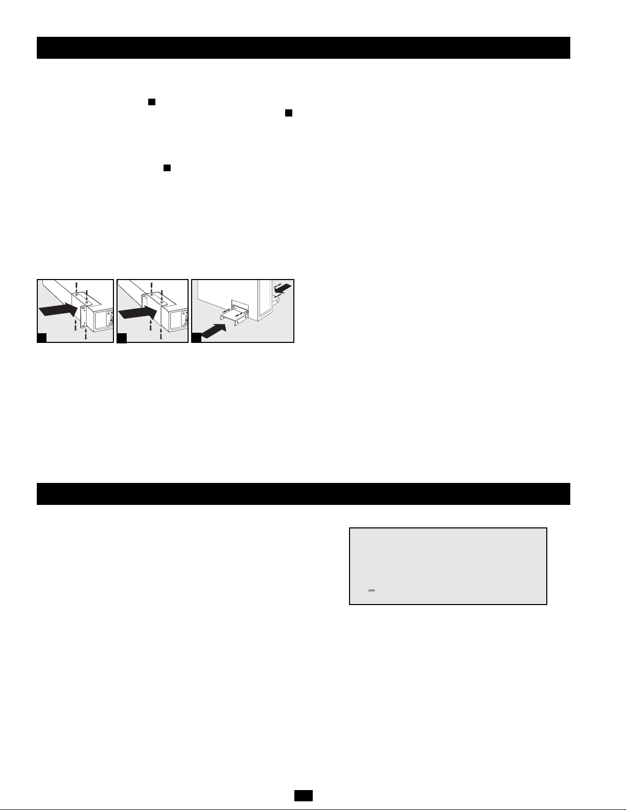
STEP 1: Place the UPS in a horizontal or vertical (tower) position.
To install the UPS in a 4-post rack, attach the included hardware to the
UPS as shown in diagram . To install the UPS in a 2-post rack,
attach the included hardware to the UPS as shown in diagram .
Then, using an assistant if necessary, lift the UPS and attach it to a
standard rack with user-supplied hardware. The UPS will stand in a
tower position without the aid of the included hardware. For increased
stability, however, Tripp Lite recommends attaching the included
hardware as shown in diagram . In either position, the user must
determine the fitness of hardware and procedures before installation.
The UPS and included hardware are designed for common rack types
and may not be appropriate for all applications. The LCD display may
be rotated to match the orientation of the UPS. Carefully insert a small
tool in the slots at the side of the LCD to remove it from the UPS
housing, then rotate the LCD and press it back into place.
CAUTION: To balance the UPS safely when placed in a vertical
position, make sure the LCD Display is located at the top of the
front panel.
STEP 2: Connect a user-supplied power cord* to the UPS, then
plug the UPS into a wall outlet.**
After plugging the UPS into a wall outlet, push the ON/OFF button
for one second to turn the UPS on (see Basic Operation section).
Please Note! The UPS will not turn on automatically in the
presence of live utility power.
*The UPS system does not include an input power cord. The user-supplied power cord
should have an IEC-320-C13 connector (commonly found on detachable power cords
for desktop computers) at one end in order to connect to the AC input of the UPS.
**Use an outlet that doesn't share a circuit with a heavy electrical load such as an air
conditioner or refrigerator.
STEP 3: Plug your equipment into the UPS.
Insert the female connectors of the detachable power cords that
came with the UPS system into the AC inputs of the attached
equipment. Insert the male connectors into any of the UPS system's
available outlets.
The UPS is designed to support electronic equipment only.
Connected equipment will overload the UPS if the total VA ratings
for all the equipment connected to the outlets exceeds the UPS
Output Capacity. To find VAratings, look at equipment nameplates.
If the equipment is listed in amps, multiply the number of amps by
230 volts to determine VA. (Example: 1 amp × 230 volts = 230 VA).
If unsure whether the outlets are overloaded, run a self-test (see
“MUTE/TEST” Button description).
STEP 4: Optional Installation. The UPS includes USB and RS-232
communication ports as well as Tel/DSL/Ethernet and Coaxial
surge protection jacks. These connections are optional; the UPS
will work properly without these connections.
Not compatible with PoE (Power over Ethernet) applications.
C
B
A
A
C
B
Quick Installation
Storage
To avoid battery drain, all connected equipment should be turned off
and disconnected from the UPS. Press and hold the ON/OFF button
for one second. Your UPS will be completely turned off (deactivated),
and will be ready for storage. If you plan on storing your UPS for an
extended period, fully recharge the UPS batteries every three months.
Plug the UPS into a live AC outlet, turn it on by pressing and holding
the ON/OFF button for one second, and allow the batteries to
recharge for 24 hours. If you leave your UPS batteries discharged for
a long period of time, they will suffer a permanent loss of capacity.
Note on Labeling
Two symbols are used on the label.
V~ : AC Voltage
V : DC Voltage
Page 3
3
Basic Operation
(Front Panel)
“ON/OFF” Button
• To Turn the UPS On: Press and hold the ON/OFF Button for one
second.* If utility power is absent, pressing the Button will “coldstart” the UPS, i.e. turn it on and supply power from battery.**
• To Turn the UPS Off: Press and hold the ON/OFF Button for one
second.* The UPS will be turned off completely.
* The alarm will beep once after one second has passed. ** Providing runtime
proportionate to the UPS battery's level of charge.
“MUTE/TEST” Button
• To Silence (or “Mute”) UPS Alarms: Briefly press and release
the MUTE/TEST button. Note: continuous alarms that warn
to shut down connected equipment immediately cannot be
silenced.
• To Run a Self-Test: with the UPS plugged in and turned on,
press and hold the MUTE/TEST button for two seconds.
Continue holding the button until the alarm beeps several times
and the UPS performs a self-test. See “Results of a Self-Test”
below. Note: connected equipment may remain connected during
a self-test.
CAUTION! Do not unplug the UPS to test the battery. This will
remove safe electrical grounding and may introduce a
damaging surge into network connections.
Results of a Self-Test: The test will last approximately 10 seconds
as the UPS switches to battery to test load capacity and charge. All
LCD Display icons will be illuminated and the UPS alarm will
sound.
•If the “FAULT” icon remains lit and the alarm continues to
sound after the test, the battery-supported outlets are overloaded.
To clear the overload, unplug some equipment from the
battery-supported outlets and run the self-test repeatedly until
the “FAULT” icon is no longer lit and the alarm is no longer
sounding.
CAUTION! Any overload that is not corrected by the user
immediately following a self-test may cause the UPS to shut
down and cease supplying output power in the event of a
blackout or brownout.
• If the “REPLACE” icon remains lit and the alarm continues to
sound after the test, the UPS batteries need to be recharged
or replaced. Allow the UPS to recharge continuously for 24
hours, and repeat the self-test. If the icon continues to
illuminate after repeated self tests, contact Tripp Lite for service.
Battery replacement should only be performed by
qualified service personnel. If the UPS requires battery
replacement, Tripp Lite offers a complete line of replacement
batteries at www.tripplite.com.
LCD Display
The LCD Display indicates a variety of UPS operational
conditions. All descriptions apply when the UPS is plugged into an
AC outlet and turned on. The LCD display may be rotated to match
the orientation of the UPS. Carefully insert a small tool in the slots
at the side of the LCD to remove it from the UPS housing, then
rotate the LCD and press it back into place.
3-1) “INPUT VOLTAGE” Meter: This meter measures, in real
time, the AC voltage that the UPS system receives from the utility
wall outlet. Although the meter may occasionally display input
voltages which stray (due to poor quality utility service) outside
the range of standard computer tolerance, rest assured that the
UPS is designed to continuously supply connected equipment
with stable, computer-grade output through the use of automatic
voltage regulation. In the event of a blackout (power loss), severe
brownout (low power) or overvoltage (high power), the UPS will
rely on the internal battery to supply computer-grade output
voltage.
3-2) “BATTERY CAPACITY” Meter: This meter displays the
approximate charge level (in 20% increments) of the internal
battery. During a blackout or severe brownout, the UPS will
switch to battery power, the “ON BAT” icon will be illuminated
and the charge level will deplete.
3-3) “AVR” (Automatic Voltage Regulation) Icon: This icon
will illuminate whenever the UPS is automatically correcting low
AC line voltage without depleting battery power. This is a normal,
automatic operation of the UPS, and no action is required.
3-4) “REPLACE” (Battery Recharge/Replace) Icon: This icon
will illuminate and an alarm will sound after a self-test to indicate
the UPS battery needs to be recharged or replaced. Allow the UPS
to recharge continuously for 24 hours, and repeat the self-test. If the
icon continues to illuminate, contact Tripp Lite for service. Battery
replacement should only be performed by qualified service
personnel. If the UPS requires battery replacement, Tripp Lite
offers a complete line of replacement batteries at www.tripplite.com.
3-5) “ON BAT” (On Battery) Icon: During a severe brownout or
blackout, this icon illuminates and an alarm sounds (4 short beeps
followed by a pause) to indicate the UPS is operating from its
internal batteries. Monitor the “Battery Capacity” Meter to
determine the approximate battery charge level available to
support equipment. During a prolonged brownout or blackout, the
alarm will sound continuously (and the “BATTERY CAPACITY”
Meter will show one 20% capacity segment shaded) to indicate
the batteries are nearly out of power; save files and shut down
your equipment immediately.
3-6) “FAULT” Icon: This icon will illuminate and an alarm will
sound after a self-test to indicate the battery-supported outlets are
overloaded. To clear the overload, unplug some of the equipment
from the battery-supported outlets and run the self-test repeatedly
until the icon is no longer illuminated and the alarm is no longer
sounding.
CAUTION! Any overload that is not corrected by the user
immediately following a self-test may cause the UPS to shut
down and cease supplying output power in the event of a
blackout or brownout.
3-7) LCD Dimmer: Adjusts the brightness of the LCD Display.
ON/OFF Button
MUTE/TEST Button
1
2
LCD Display
3
3-1
3-2
3-3
3-4
3-5
3-6
1
2
3
3-7
Page 4

Battery Backup/Surge Protected Outlets: These IEC-320-C13
outlets provide both battery backup and surge protection. Plug
your computer, monitor and other critical equipment into these
outlets. NOTE: DO NOT PLUG LASER PRINTERS INTO
THESE OUTLETS.
USB or Serial Communication Port: These ports can connect
your UPS to a computer for automatic file saves and unattended
shutdown in the event of a power failure. Use with Tripp Lite’s
PowerAlert Software and appropriate USB or DB9 serial cable.
PowerAlert Software is available for download FREE at
www.tripplite.com. Note: This connection is optional. The UPS
will work properly without this connection.
CAUTION: Users should take care to minimize electro-static
events. In the event of a severe electro-static discharge on or
near the USB port, this UPS may shut down automatically. In
the case of a shutdown, the UPS must be turned back on.
Tel/DSL/Ethernet Protection Jacks: RJ-45 jacks provide surge
protection for a single telephone, fax, modem, DSL or Ethernet
line. Connect a telephone cord or Ethernet cable from the wall
jack or original data source jack directly to the Tel/DSL/Ethernet
jack labeled “IN.” Connect a telephone cord or Ethernet cable
from the Tel/DSL/Ethernet jack labeled “OUT” directly to the
equipment to be protected. The UPS system must be the first item
connected to the wall jack or original data source jack. The UPS
system must be plugged into a grounded AC outlet in order to
provide surge protection to connected equipment. Connecting
your equipment to these jacks is optional. Your UPS will work
properly without this connection.
AC Input: This IEC-320-C14 connector accepts a usersupplied power cord with a plug appropriate for the local site's
utility outlets.
Coaxial Protection Jacks: Gold-plated jacks provide surge
protection for a single coaxial line. Connect a coaxial cable from
the wall jack directly to the coaxial jack labeled “IN.” Connect a
coaxial cable from the coaxial jack labeled “OUT” directly to the
equipment to be protected. The UPS system must always be the
first item connected to the wall jack. The UPS system must be
plugged into a grounded AC outlet in order to provide surge
protection to connected equipment. Make sure coaxial cables
connected to satellite dishes, antennas, etc. are also grounded.
Connecting your equipment to these jacks is optional. The UPS
will work properly without this connection.
Mounting Hardware: Adapts the UPS to either tower or 2U rack
installation.
Power Sensitivity Dial: The default setting for the dial is full
counterclockwise rotation. The default allows the UPS to protect
against waveform distortions in the AC input power by switching
to battery power for as long as the problem is detected. At sites
supplied by substandard utility power or generator power, chronic
waveform distortion (or frequent brownouts) could cause the UPS
to switch to battery too often, draining battery reserves. It may be
possible to optimize the level of protection for a particular site by
experimenting with sensitivity settings. As the dial is turned
clockwise, the UPS becomes more tolerant of waveform
variations. WARNING: Equipment may malfunction when
exposed to distorted AC waveforms. When experimenting with
sensitivity settings, operate connected equipment in a safe “test
mode” in order to evaluate results without disrupting critical
operations. Continue the test until all expected line conditions
have been encountered.
Circuit Breaker: If the current drawn by the equipment
connected to the UPS exceeds the Maximum Load Rating for
longer than a few seconds, the circuit breaker will activate and
interrupt AC power to prevent possible damage. When the circuit
breaker activates, its plunger will pop up. Disconnect excess
equipment and allow the breaker to cool one minute before
depressing the plunger to reset the breaker.
4
Basic Operation
(Rear Panel)
Tel/DSL/Ethernet
Protection Jacks
USB Port/RS-232
Serial Port (DB9)
AC InputBattery Backup/Surge
Protected Outlets
Before returning your UPS for service, follow these steps: 1. Review the installation and
operation instructions in this manual to ensure that the service problem does not originate from
a misreading of the instructions. 2. If the problem continues, do not contact or return the UPS to
the dealer. Instead, call Tripp Lite at (773) 869-1234 domestically or (773) 869-1212
internationally. A service technician will ask for the UPS model number, serial number and
purchase date and will attempt to correct the problem over the phone. 3. If the problem requires
service, the technician will issue you a Returned Material Authorization (RMA) number, which is
required for service. If you require packaging, the technician can arrange to send you proper
packaging. Securely pack the UPS to avoid damage during shipping. Do not use Styrofoam
beads for packaging. Any damages (direct, indirect, special, incidental or consequential) to the
UPS incurred during shipment to Tripp Lite or an author ized Tripp Lite service center is not
covered under warranty. UPS Systems shipped to Tripp Lite or an authorized Tripp Lite service
center must have transportation charges prepaid. Mark the RMA number on the outside of the
package. If the UPS System is within the 2-year warranty period, enclose a copy of your sales
receipt. Return the UPS for service using an insured carrier to the address given to you by the
Tripp Lite service technician.
Regulatory Compliance Identification Numbers
For the purpose of regulatory compliance certifications and identification, your Tripp Lite
product has been assigned a unique series number. The series number can be found on the
product nameplate label, along with all required approval markings and information. When
requesting compliance information for this product, always refer to the series number. The
series number should not be confused with the marking name or model number of the product.
Tripp Lite follows a policy of continuous improvement. Product specifications are subject to
change without notice.
9
10
8
7
4
5
6
4 5 6 7
Coaxial
Protection Jacks
8 9
Mounting Hardware
Power Sensitivity
Dial
10
11
Circuit Breaker
11
Service
Page 5

5
Instrucciones de seguridad importantes
GUARDE ESTAS INSTRUCCIONES
Este manual contiene instrucciones y advertencias que deben seguirse durante la instalación, operación y almacenamiento de todos los UPS de
Tripp Lite. El incumplimiento de estas advertencias anulará su garantía.
Advertencias sobre la ubicación del UPS
• El UPS está diseñado sólo para empleo en interiores en un ambiente
controlado, lejos del exceso de humedad, calor/frío, contaminantes
conductores, polvo o luz solar directa.
• Deje una cantidad de espacio adecuada alrededor del UPS para una
buena ventilación.
• No monte esta unidad con el panel frontal o con el panel trasero
hacia abajo (Bajo ningún ángulo o inclinación). Si lo monta de esta
manera, inhibirá seriamente el sistema de enfriamiento interno de
la unidad; lo que finalmente causará daños al producto que no
están cubiertos por la garantía.
Advertencias sobre la conexión del UPS
• Conecte su UPS directamente a una toma de corriente de CA puesta a
tierra apropiadamente. No conecte el UPS a si mismo porque se dañará.
• No modifique el enchufe del UPS ni emplee un adaptador que
elimine su conexión a tierra.
• No use cordones de extensión para conectar el UPS a una toma de
CA. Su garantía quedará anulada si utiliza cualquier dispositivo
que no sea un supresor de sobretensiones Tripp Lite para conectar
su UPS a una toma de corriente.
• Si el UPS recibe energía de un generador de CA accionado por
motor, el generador debe proporcionar una salida limpia y filtrada
de grado computadora.
Advertencias sobre la conexión de equipos
• No utilice sistemas UPS de Tripp Lite para aplicaciones de soporte de
vida en las que un funcionamiento defectuoso o una falla del UPS
pudiera causar un mal funcionamiento o una alteración importante en
el funcionamiento de un dispositivo de soporte de vida.
• No conecte supresores de sobretensiones ni cordones de extensión a la
salida de su UPS. Esto podría dañar el UPS y anular las garantías del
supresor de sobretensiones y del UPS.
Advertencias sobre la batería
• Su UPS no requiere ningún mantenimiento de rutina. No lo abra por
ningún motivo. No hay partes en su interior que requieran
mantenimiento por parte del usuario.
• Las baterías presentan un peligro de choque eléctrico y quemaduras
como producto de las altas corrientes de cortocircuito. Observe las
precauciones apropiadas. No deseche las baterías en un incinerador.
No abra el UPS ni las baterías. No ponga los terminales de la batería
en cortocircuito o en puente con ningún objeto. Apague y desconecte
el UPS antes de reemplazar la batería. Use herramientas con mangos
aislados. No hay piezas que el usuario pueda reparar dentro del UPS.
El reemplazo de baterías debe ser realizado solamente por personal de
servicio autorizado usando la misma cantidad y tipo de baterías
(plomo-ácido, selladas). Las baterías son reciclables. Consulte la
reglamentación local para los requisitos de disposición de desechos.
Tripp Lite ofrece una línea completa de baterías de reemplazo en
www.tripplite.com.
• No trate de agregar baterías externas al UPS.
Manual del propietario
UPS digital SMX1500LCD
No apropiado para aplicaciones móviles.
© 2007 Tripp Lite. Todos los derechos reservados.
1111 W. 35th Street • Chicago, IL 60609 USA • +1 773 869 1234 • www.tripplite.com
Page 6

6
Almacenamiento
PASO 4: Instalación opcional. El UPS incluye puertos de comunicación
USB y RS-232 así como Tel/DSL/Ethernet y conectores coaxiales con
protección contra sobretensiones. Estas conexiones son opcionales; el
UPS funcionará correctamente sin ellas.
No compatible con aplicaciones PoE (Energía sobre Ethernet).
PRECAUCIÓN: El UPS debe estar conectado a una toma de CA con
energía y encendido por 24 horas después de la instalación inicial para
cargar completamente la batería interna. Su equipo conectado recibirá
energía de CA suministrada de la red (si está disponible) inmediatamente
después que el UPS esté conectado y encendido; sin embargo, su equipo
conectado no podrá recibir completo respaldo de batería en el caso de una
falla del servicio eléctrico o una severa baja de voltaje a menos que la
batería interna del UPS esté totalmente cargada.
Desconecte todo el equipo de la UPS. Presione el botón CON./DESC.
ON/OFF de la UPS para un segundo o más - esto desactivará la UPS. La
UPS es lista ahora para el almacenaje. Si la UPS está en el almacenaje por
un período del tiempo extendido, recargue las baterías totalmente cada tres
meses. Para recargar las baterías totalmente: (1) conecta la UPS con un
enchufe eléctrico, (2) prensa el botón CON./DESC. ON/OFF para un
segundo o más, (3) recarga las baterías por 24 horas. Si las baterías siguen
siendo descargado por un período del tiempo extendido, perderán
capacidad permanentemente.
Nota sobre el rotulado
Se usan dos símbolos en la etiqueta.
V~ : Voltaje CA
V : Voltaje CC
Instalación rápida
PASO 1: Coloque el UPS en posición horizontal (montaje en bastidor) o
vertical (“torre”). Para montar el UPS en un bastidor de 4 postes, conecte
los accesorios incluidos al UPS como se observa en el diagrama . Para
montar el UPS en un bastidor de 2 postes, conecte los accesorios incluidos
al UPS como se observa en el diagrama . Luego, con un ayudante si es
necesario, levante el UPS y móntelo en un bastidor estándar o en una caja
de bastidor con los materiales suministrados por el usuario. El UPS podrá
estar en la posición de torre sin ayuda del material incluido. Sin embargo,
para la estabilidad de adicional, Tripp Lite le recomienda conectar los
accesorios incluidos como se observa en el diagrama . El UPS y el
material incluido están diseñados para bastidores comunes y cajas de
bastidor, y pueden no ser apropiados para todas las aplicaciones. Para girar
la pantalla: Introduzca una pequeña herramienta en las ranuras en los lados
de la pantalla y retírela de la caja del UPS; gire la pantalla, y colóquela a
presión nuevamente en la caja del UPS.
PRECAUCIÓN: Para equilibrar el UPS en forma segura cuando
está en posición vertical (“torre”), asegúrese que la pantalla LCD
esté ubicada en la parte superior del panel frontal.
PASO 2: Conecte un cordón de alimentación suministrado por el
usuario* en el UPS, luego conecte el UPS en una toma de corriente.**
Después de conectar el UPS en una toma de corriente de pared,
presione el botón ON/OFF (ENCENDIDO/APAGADO) durante un
segundo para encenderlo (vea la sección Operación Básica). Nota
importante El UPS no se encenderá automáticamente cuando haya
voltaje en la red.
* El UPS no incluye un cordón de alimentación de entrada. El cordón de alimentación
suministrado por el usuario debe tener un conector IEC-320-C13 (comúnmente
encontrado como cordón de alimentación separable de su ordenador para PCs de
escritorio) en un extremo, para conectarlo a la entrada de corriente alterna del UPS.
** Use una salida que no comparta el circuito con carga eléctrica pesada, tal como
un equipo de aire acondicionado o refrigerador.
C
B
A
A
C
B
PASO 3: Conecte sus equipos en el UPS. Inserte el extremo hembra del
cordón de alimentación separable incluido con su UPS en la entrada de
CA de su computadora. Inserte el extremo macho del cordón del UPS
en cualquier receptáculo hembra de salida del UPS.
Su UPS sólo está diseñado para dar soporte a equipos electrónicos. Si
la capacidad total en VA para todos los equipos conectados a las salidas
excede la capacidad de salida del UPS, éste se sobrecargará. Para
averiguar la capacidad de sus equipos en VA, revise sus placas. Si la
capacidad del equipo está indicada en amperios, multiplique los
amperios por 230 para determinar los VA. (Ejemplo: 1 amperio X 230
= 230 VA) Si no está seguro de si ha sobrecargado las salidas, ejecute
una auto-prueba (vea la descripción del botón “MUTE/TEST”(SILENCIO/PRUEBA))
Page 7

7
Botón ENCENDIDO/APAGADO
• Para encender el UPS: Presione y mantenga presionado el botón
ENCENDIDO/APAGADO durante un segundo.* Si no hay
energía en la red, presionando el botón el UPS “arrancará en frío”,
es decir, se encenderá y suministrará energía de su batería.**
• Para apagar el UPS: Presione y mantenga presionado el botón
ENCENDIDO/APAGADO durante un segundo.* El UPS se apagará
por completo (quedará desactivado).
*La alarma emitirá un breve pitido después de pasado un segundo. ** Proporcionando un
tiempo de respaldo dependiente del nivel de carga de la batería del UPS.
Botón SILENCIO/PRUEBA
• Para silenciar las alarmas UPS: Presione brevemente el botón
SILENCIO/PRUEBA y luego suéltelo. Nota: Las alarmas continuas
(advirtiéndole apagar inmediatamente el equipo conectado) no
pueden ser silenciadas.
• Para ejecutar una auto-prueba: Con su UPS conectado y
encendido, presione y mantenga presionado el botón SILENCIO/
PRUEBA por dos segundos. Siga presionando el botón hasta que la
alarma suene varias veces y el UPS realice una auto-prueba. Vea
“Resultados de una auto-prueba” en una sección posterior. Nota:
Puede dejar equipos conectados durante una auto-prueba.
¡PRECAUCIÓN! No desconecte su UPS para probar su batería.
Esto eliminaría la conexión de seguridad a tierra y podría
introducir sobretensiones dañinas en sus conexiones de red.
Resultados de una auto-prueba: La prueba durará cerca de 10
segundos mientras el UPS conmuta a batería para probar su capacidad
de carga y recarga. Todos los iconos de la pantalla LCD estarán
iluminados y la alarma sonará.
• Si el icono “FAULT” (FALLA) permanece encendido y la alarma
sigue sonando después de la prueba, las salidas soportadas por
batería están sobrecargadas. Para eliminar la sobrecarga, desconecte
algunos equipos de las salidas soportadas por baterías y ejecute la
auto-prueba varias veces hasta que el icono “FAULT” (FALLA) ya
no esté encendido y la alarma ya no suene.
¡PRECAUCIÓN! Cualquier sobrecarga no corregida por el
usuario inmediatamente después de una auto-prueba, puede
causar que el UPS se apague y deje de suministrar energía de salida
en el caso de una falla del servicio eléctrico o una baja de voltaje.
• Si el icono “REPLACE” (REEMPLAZAR) sigue encendido y la
alarma continúa sonando después de la prueba, las baterías del UPS
deben recargarse o reemplazarse. Permita que el UPS se recargue
continuamente por 24 horas y repita la auto-prueba. Si el icono
continúa iluminado después de varias auto-pruebas, solicite servicio
a Tripp Lite. El reemplazo de baterías debe ser realizado solamente
por personal de servicio calificado. Si el UPS requiere un reemplazo
de batería, Tripp Lite ofrece una línea completa de baterías en
www.tripplite.com.
Pantalla LCD
La pantalla LCD indica diferentes condiciones de operación del UPS.
Todas las descripciones se aplican cuando el UPS está conectado a una
salida de CA y encendido. La pantalla LCD puede ser girada para mejor
visualización, ya sea que el UPS esté en posición horizontal o vertical
(“torre”). Para girar la pantalla, introduzca una pequeña herramienta en
las ranuras en los lados de la pantalla y retírela de la caja del UPS;
gírela y colóquela a presión nuevamente en la caja del UPS.
3-1) Medidor de “VOLTAJE DE ENTRADA”: Este medidor mide,
en tiempo real, el voltaje de CA que el UPS está recibiendo de la toma
de corriente de la red. Aunque el medidor puede mostrar
ocasionalmente voltajes de entrada que se desvían (debido a la baja
calidad del servicio de la red) del rango de tolerancia estándar de
computadora, puede estar seguro que el UPS está diseñado (mediante
el empleo de regulación automática de voltaje) para suministrar
continuamente al equipo conectado un voltaje de salida estable de
grado computadora. En el caso de una falla del servicio eléctrico
(pérdida de energía), una severa baja de voltaje (baja de potencia) o
un sobrevoltaje (subida de potencia), el UPS empleará su batería
interna para suministrar voltaje de salida grado computadora.
3-2) Medidor de “DE BATERÍA”: Este medidor muestra el nivel
aproximado de carga (con incrementos de 20%) de la batería interna
del UPS. Durante una falla del servicio eléctrico o una severa baja de
voltaje, el UPS cambiará a energía de batería, el icono “ON BAT” (CON
BAT.) se iluminará, y el nivel de carga se reducirá considerablemente.
3-3) Icono “AVR” (Regulación automática de voltaje): Este icono
se iluminará siempre que su UPS esté corrigiendo automáticamente el
bajo voltaje de la línea de CA sin consumir energía de la batería. Esta
es una operación normal y automática de su UPS y no requiere
ninguna acción de su parte.
3-4) Icono “REPLACE” (REEMPLAZAR) (Recargar/
Reemplazar batería): Este icono se iluminará y una alarma sonará
después de una auto-prueba para indicar que la batería del UPS
necesita ser recargada o reemplazada. Permita que el UPS se recargue
continuamente por 24 horas y repita la auto-prueba. Si el icono sigue
iluminado, contacte con Tripp Lite para que le brinden servicio. El
reemplazo de baterías debe ser realizado solamente por personal de
servicio calificado. Si el UPS requiere un reemplazo de batería,
Tripp Lite ofrece una línea completa de baterías en
www.tripplite.com.
3-5) Icono “ON BAT” (Con batería): Durante una severa baja de
voltaje o una falla del servicio, este icono se iluminará y una alarma
sonará (4 pitidos cortos seguidos de una pausa) para indicar que el
UPS está operando con sus baterías internas. Controle el medidor
“Capacidad de batería” para determinar al nivel aproximado de carga
disponible para dar soporte al equipo. Durante una baja de voltaje
prolongada o una falla del servicio eléctrico, la alarma sonará
continuamente (y el medidor “CAPACIDAD DE BATERÍA”
mostrará un segmento de 20% de capacidad sombreado) para indicar
que las baterías del UPS están casi agotadas; debe guardar los
archivos y apagar su equipo de inmediato.
3-6) Icono “FAULT” (FALLA): Este icono se iluminará y una
alarma sonará después de una auto-prueba para indicar que las salidas
soportadas por batería están sobrecargadas. Para eliminar la
sobrecarga, desconecte algunos equipos de las salidas soportadas por
baterías y ejecute la auto-prueba varias veces hasta que el icono ya no
esté iluminado y la alarma ya no suene.
¡PRECAUCIÓN! Cualquier sobrecarga no corregida por el
usuario inmediatamente después de una auto-prueba, puede
causar que el UPS se apague y deje de suministrar energía de salida
en el caso de una falla del servicio eléctrico o una baja de voltaje.
3-7) Dimmer de la Pantalla LCD: Ajusta el brillo de la Pantalla LCD.
Botón Encendido/Apagado
Botón
SILENCIAR/PRUEBA
1
2
Pantalla LCD
3
3-1
3-2
3-3
3-4
3-5
3-6
1
2
3
3-7
Operación básica
(Panel frontal)
Page 8

Operación básica
(Panel posterior)
Salidas con respaldo de batería/Con protección contra
sobretensiones: Proporcionan respaldo de baterías y protección
contra sobretensiones. Conecte su computadora, su monitor y otros
equipos críticos en estas salidas. NOTA: NO CONECTE
IMPRESORAS LÁSER EN ESTAS SALIDAS.
Puertos de comunicación USB o DB9: Estos puertos pueden
conectar su UPS a cualquier computadora para guardar
automáticamente sus archivos y apagar su computadora sin atención,
en el caso de una falla de energía. Se utilizan con el software
PowerAlert de Tripp Lite y con un cable USB o DB9 adecuado. Es
posible que su UPS incluya un CD de PowerAlert y un cable USB o
DB9; si es así, introduzca el CD en su computadora y siga las
instrucciones de instalación. Si el software PowerAlert y el cable
apropiado no estaban incluidos con su UPS, puede obtener el
software GRATUITAMENTE a través de la Web en
www.tripplite.com. Cualquier conector de entrada-salida DB9 o un
cable USB suministrado por el usuario pueden usarse para conectar
su UPS a su computadora.
PRECAUCIÓN: Los usuarios deben tomar las precauciones
necesarias para reducir al mínimo los fenómenos electrostáticos.
En caso de una descarga electrostática severa en o cerca del
puerto USB, este UPS puede apagarse automáticamente. En caso
de apagarse, el UPS tendrá que ser encendido nuevamente.
Conectores para protección de línea Tel/DSL/Ethernet: Los
conectores RJ-45 proporcionan protección contra sobretensiones a
una línea telefónica, de fax, módem, DSL o Ethernet individual.
Conecte un cordón telefónico o cable Ethernet desde el conector de
la pared o desde el conector de la fuente original de datos,
directamente al conector Tel/DSL/Ethernet rotulado “IN” (entrada).
Conecte un cordón telefónico o cable Ethernet desde el conector
rotulado “OUT” (salida) directamente al equipo que debe proteger.
El UPS debe ser el primer elemento conectado al conector de la pared
o conector de la fuente original de datos. El UPS debe estar conectado en
una toma de corriente alterna con toma de tierra para que funcione la
protección al equipo conectado. La conexión de su equipo a estos
conectores es opcional. Su UPS funcionará correctamente sin esta
conexión.
Entrada de CA: Este conector IEC-320-C14 acepta un cordón de
alimentación suministrado por el usuario con un enchufe apropiado
para las salidas de su servicio eléctrico local.
Conectores para protección coaxial: Los conectores enchapados en
oro proporcionan protección contra sobretensiones para una línea
coaxial individual. Conecte un cable coaxial desde el conector de la
pared directamente al conector coaxial rotulado “IN” (entrada).
Conecte un cable coaxial desde el conector coaxial rotulado “OUT”
(salida) directamente al equipo que debe proteger. El UPS siempre
debe ser el primer elemento conectado al conector de pared. El UPS
debe estar conectado en una toma de corriente alterna con toma de
tierra para que funcione la protección al equipo conectado. Asegúrese
de que los cables coaxiales conectados a las antenas parabólicas,
antenas convencionales, etc., también estén puestos a tierra.
Accesorios para montaje: Adapta el UPS para aplicaciones bastidor
(2U) o de montaje en torre.
Dial sensibilidad de energía: Este dial normalmente está regulado
totalmente en el sentido contrario al reloj, lo que permite al UPS
proteger contra distorsiones de forma de onda en su entrada de
corriente alterna. Cuando ocurren dichas distorsiones, normalmente
el UPS conmutará para proporcionar una onda sinusoidal PWM de
energía de sus baterías de reserva por tanto tiempo como la distorsión
continúe. En algunas áreas con un suministro de energía de la red de
baja calidad, o donde la energía de entrada del UPS provenga de un
generador de respaldo, las frecuentes bajas de voltaje y/o la crónica
distorsión de la forma de onda, pueden causar que el UPS conmute a
alimentación por baterías con demasiada frecuencia, agotando sus
baterías de reserva. Es posible reducir la frecuencia con que su UPS
conmuta a baterías debido a la distorsión de la forma de onda o a
bajas de voltaje, experimentando con diferentes ajustes para este dial.
A medida que el dial es girado en el sentido del reloj, el UPS se
vuelve más tolerante a las variaciones en la forma de onda de la
corriente alterna de entrada. NOTA: A mayor ajuste del dial en el
sentido del reloj, mayor será el grado de distorsión de la forma de
onda que el UPS permitirá que pase al equipo conectado. Al
experimentar con diferentes ajustes para este dial, opere el equipo
conectado en un modo de prueba seguro, de modo que el efecto de
cualquier distorsión de la forma de onda en la salida del UPS sobre el
equipo pueda evaluarse sin desestabilizar ninguna operación crítica.
La prueba debe durar lo suficiente para asegurar que se encuentren
todas las condiciones de línea esperadas.
Interruptor automático: Si la corriente consumida por el equipo
conectado a la sistema UPS excede la máxima capacidad de carga por
más de unos cuantos segundos, el interruptor automático se activará e
interrumpirá la alimentación de CA para evitar posibles daños.
Cuando un interruptor automático dispara, su émbolo se extiende.
Desconecte el equipo en exceso de la sistema UPS y permita que el
interruptor automático se enfríe un minuto antes de presionar el
émbolo para restablecer el interruptor automático.
Puertos de
comunicación
USB o DB9
Entrada de CASalidas con respaldo
de batería/Con
protección contra
sobretensiones
Conectores para
Tel/DSL/Ethernet
5
6
7
8
9
10
4 5 6 7 8 9
10 11
11
Accesorios para
montaje
Interruptor
automático
Conectores para
protección coaxial
Dial sensibilidad
de energía
Antes de enviar su UPS para que le presten servicio, siga los siguientes pasos: 1. Verifique las instrucciones de
instalación y operación en este manual para asegurarse que el problema de servicio no sea causado por una mala
interpretación de las instrucciones. 2. Si el problema continúa, no contacte con el distribuidor ni devuelva el UPS.
En su lugar, llame a Tripp Lite al (773) 869-1234 en EE.UU. o (773) 869-1212 desde fuera de EE.UU. Un técnico
de servicio le pedirá el modelo, número de serie y fecha de compra del UPS y tratará de resolver el problema a
través del teléfono. 3. Si el problema requiere servicio, el técnico le emitirá un número de Autorización de
devolución de mercadería (RMA), necesario para que le presten servicio. Si requiere embalaje, el técnico puede
hacer arreglos para que le envíen el material adecuado. Empaque el UPS en forma segura para evitar daños durante
el despacho. No use camas de espuma de estireno para el embalaje. Cualquier daño (directo, indirecto, especial,
accidental o resultante) al UPS producido durante el despacho a Tripp Lite o a un centro autorizado de servicio
Tripp Lite no estará cubierto por la garantía. Los sistemas UPS enviados a Tripp Lite o a algún centro de servicio
autorizado de Tripp Lite deben tener los cargos de transporte prepagados. Marque el número RMA en la parte
externa del paquete embalado. Si el UPS está dentro del período de garantía de 2 años, adjunte una copia de su
recibo de compra. Devuelva el UPS para servicio a la dirección dada por el técnico de Tripp Lite utilizando un
transportista asegurado.
4
Cumplimiento de las normas de los números de identificación
Para fines de identificación y certificación del cumplimiento de las normas, su producto Tripp Lite tiene
asignado un número de serie único. Puede encontrar el número de serie en la etiqueta de la placa de
identificación del producto, junto con los símbolos de aprobación e información requeridos. Al solicitar
información sobre el cumplimiento de las normas para este producto, siempre mencione el número de
serie. El número de serie no debe ser confundido con el nombre de identificación ni con el número de
modelo del producto.
Tripp Lite tiene una política de mejoramiento continuo. Las especificaciones están sujetas a cambio sin previo
aviso.
Servicio
8
Nota sobre el rotulado
Se usan dos símbolos en la etiqueta.
V~ : Voltaje CA
V : Voltaje CC
Page 9

9
Importantes consignes de sécurité
CONSERVER CES DIRECTIVES
Ce manuel contient des instructions et de avertissements que vous devez respecter durant l'installation, l'utilisation et l'entreposage des systèmes
d'onduleur UPS Tripp Lite. Ne pas tenir compte de ces mises en garde entraînera l'annulation de la garantie.
Mises en garde : Emplacement de l'onduleur
UPS
• L'onduleur UPS est conçu pour un usage en environnement contrôlé, à
l'abri de l'humidité excessive et de la chaleur ou du froid, des substances
corrosives, de la poussière et de la lumière directe du soleil.
• Maintenez un dégagement adéquat autour de l'onduleur pour garantir une
bonne circulation d'air.
• Ne pas monter l'unité avec son panneau avant ou arrière à l'envers
(quelque soit l'angle). Monter de cette façon va entraver sérieusement
le refroidissement interne de l'unité, endommageant le produit non
couvert sous garantie.
Mises en garde : Connexions de l'onduleur UPS
• Brancher votre onduleur UPS directement à une prise de secteur
correctement mise à la terre. Ne pas brancher l'onduleur sur lui-même,
cela l'endommagera.
• Ne pas modifier la fiche de l'onduleur UPS et ne pas utiliser
d'adaptateur qui éliminerait sa mise à la terre.
• Ne pas utiliser d'extensions pour brancher l'onduleur UPS à une prise
de secteur. Votre garantie sera annulée si vous utilisez autre chose que
des éliminateurs de surtension Tripp Lite pour brancher votre onduleur
UPS à une prise.
• Si une génératrice CA alimente votre onduleur UPS , elle doit fournir
une sortie propre, filtrée et classée pour ordinateur.
Mises en garde : Connexion de l'équipement
• Ne pas utiliser les systèmes d'onduleur UPS Tripp Lite dans les
applications médicales de survie où un mauvais fonctionnement ou une
panne peuvent entraîner une panne de l'équipement médical de survie ou
altérer sa performance de façon importante.
• Ne pas brancher d'éliminateurs de surtension ou de cordons prolongateurs
à la sortie de votre onduleur UPS. Cela pourrait endommager l'onduleur
UPS et annuler les garanties de l'éliminateur de surtensions et de
l'onduleur.
Mises en garde : Batterie
• Votre onduleur UPS ne nécessite pas d'entretien de routine. N'ouvrir votre
onduleur UPS sous aucun prétexte. L'utilisateur ne peut réparer aucune
pièce interne.
• Les batteries peuvent présenter un risque de choc électrique et de brûlures
dues au courant élevé de court-circuit. Prenez les précautions nécessaires.
Ne pas jeter les batteries au feu. Ne pas ouvrir l'onduleur UPS ou les
batteries. Ne pas établir de court circuit ou de pont entre les bornes de la
batterie avec un quelconque objet. Débrancher et éteindre l'onduleur UPS
avant de remplacer la batterie. Utiliser des outils avec des poignées
isolées. L'utilisateur ne réparer aucune pièce interne de l'onduleur UPS .
Seul le personnel de service autorisé peut remplacer les batteries par des
batteries du même numéro et du même type (batterie sans entretien). Les
batteries sont recyclables. Consulter les codes locaux pour les exigences
d'élimination des déchets. Tripp Lite offre une gamme complète de
batteries de remplacement à www.tripplite.com.
• Ne pas essayer d'ajouter des batteries externes à votre onduleur UPS.
Manuel du propriétaire
SMX1500LCD Système d'onduleur
UPS numérique
Ne convient pas aux applications mobiles.
1111 W. 35th Street • Chicago, IL 60609 USA • +1 773 869-1234 • www.tripplite.com
Copyright 2007 Tripp Lite. Tous droits réservés.
Page 10

10
ÉTAPE 3 : Brancher votre équipement dans l'onduleur UPS. Insérer
le fiche femelle du cordon d'alimentation détachable joint à votre
onduleur UPS dans l'entrée CA de votre ordinateur. Insérer le fiche
mâle du même cordon dans une des prises de sortie femelles de votre
onduleur UPS.
Votre onduleur UPS est seulement conçu pour protéger de l'équipement
électronique. Vous surchargerez l'onduleur si la charge nominale totale
en VA de tout l'équipement connecté aux prises de sortie excède la
puissance de sortie de l'onduleur UPS. Pour trouver la charge nominale
en Va de votre équipement, regarder sur les plaques signalétiques des
appareils. Si l'équipement est identifié en ampères, multiplier le
nombre d'ampères par 230 pour calculer la puissance. (Exemple : 1 A
x 230 = 230 VA). Si vous pensez avoir surchargé les prises, faire un
auto-test (voir la description du bouton “MUTE/TEST”).
ÉTAPE 4 : Installation en option. L'onduleur dispose de ports de
communication USB et RS-232 ports ainsi que de prises
Tel/DSL/Ethernet et coaxiale de protection contre les surtensions. Ces
connexions sont optionnelles; l'onduleur UPS fonctionnera
correctement sans ces connexions.Non compatible avec les ports
Ethernet alimentés en courant
ATTENTION : L'onduleur UPS doit être branché dans une prise de
courant active et mis en marche pendant 24 heures après
l'installation initiale pour charger complètement sa batterie
interne.Votre équipement connecté recevra le courant de secteur
(s'il est présent) immédiatement après que l'onduleur UPS a été
branché et mis en marche; cependant, votre équipement connecté
pourrait ne pas recevoir un secours de batterie complet an cas de
panne ou de baisse sévère de tension sauf si la batterie interne de
l'onduleur UPS est entièrement chargée.
Entreposage
Tous les équipements connectés doivent être arrêtés puis débranchés de
l'onduleur UPS pour éviter de vider la batterie. Appuyer sur le bouton
ON/OFF pendant une seconde. Votre onduleur sera complètement fermé
(désactivé) et sera prêt pour l'entreposage.Si vous envisagez d'entreposer
votre onduleur UPS pendant une longue période, recharger ses batteries
tous les trois mois. Brancher votre onduleur UPS dans une prise de secteur
active, le mettre en marche en appuyant sur le bouton ON/OFF pendant
une seconde et laisser la batterie se recharger pendant 24 h. Si vous laissez
vos batteries déchargées pendant une longue période, elles souffriront
d'une perte permanente de capacité.
Note sur l'étiquetage
Deux symboles sont utilisés sur
l'étiquette.
V~ : Tension CA
V : Tension CC
Installation rapide
ÉTAPE 1 : Placer l'onduleur UPS en position horizontale (montage en
bâti) ou verticale (“tour”). Pour monter l'onduleur UPS sur bâti dans un
bâti à 4 montants, fixer la quincaillerie incluse avec l'onduleur comme le
montre le schéma . Pour monter l'onduleur UPS sur bâti dans un bâti à
2 montants, fixer la quincaillerie incluse avec l'onduleur comme le montre
le schéma . Ensuite, au besoin avec l'aide d'un assistant, soulever
l'onduleur UPS et le fixer sur un bâti standard ou dans un boîtier avec de
la quincaillerie fournie par l'utilisateur. La quincaillerie incluse n'est pas
nécessaire pour que l'onduleur UPS tienne en position verticale (tour).
Cependant, pour la stabilité supplémentaire, Tripp Lite vous recommande
de fixer la quincaillerie incluse comme le montre le schéma . L'onduleur
UPS et la quincaillerie incluse sont conçus pour des types de bâti et boîtier
courants et peuvent ne pas convenir à toutes les applications. L'afficheur à
cristaux liquides peut être pivoté pour faciliter la vision, peu importe si le
UPS est en position horizontale ou verticale (“tour”). Pour faire pivoter
l'afficheur : insérez délicatement un petit outil dans les fentes situées sur
le côté de l'afficheur pour le faire sortir de son boîtier ; faites pivoter
l'afficheur et enclenchez le de nouveau dans le boîtier du UPS.
ATTENTION : Pour équilibrer l'onduleur en toute sécurité
lorsqu'il est en position verticale, assurez-vous que l'afficheur ACL
est situé au sommet du panneau avant.
ÉTAPE 2 : Connecter un cordon* d'alimentation fourni par
l'utilisateur à l'onduleur et brancher celui-ci dans une prise
murale**. Après le branchement de l'onduleur dans une prise murale,
appuyer sur le bouton ON/OFF pendant une seconde pour le mettre en
marche (voir le chapitre Fonctionnement de base). Veuillez noter!
L'onduleur ne se mettra pas automatiquement en marche en présence
de courant de secteur.
*Le cordon d'alimentation n'est pas fourni avec l'onduleur. Le cordon* d'alimentation
fourni par l'utilisateur doit disposer d'un connecteur IEC-320-C13 (qu'on trouve
couramment sur les cordons d'alimentation amovibles des ordinateurs de bureau) à
une extrémité pour connecter l'entrée CA à l'onduleur.
**Utiliser une prise qui ne partage pas de circuit avec une lourde charge électrique
comme un climatiseur ou un réfrigérateur.
C
B
A
A
C
B
Page 11

11
Fonctionnement de base
(panneau avant)
Bouton “ON/OFF” (Marche/Arrêt)
• Pour mettre en marche l'onduleur UPS : Appuyer sur le bouton
ON/OFF pendant une seconde*. S'il n'y a pas de courant, appuyer sur
le bouton mettra en marche l'onduleur UPS “ à froid ”, c.-à-d. le
mettra en marche et l'alimentera à partir des batteries**.
• Pour arrêter l'onduleur UPS : Appuyer sur le bouton ON/OFF
pendant une seconde*. L'onduleur UPS sera complètement désactivé.
* L'alarme bipera une fois brièvement après une seconde. ** Fournissant une durée de
fonctionnement proportionnelles à la charge de la batterie de l'onduleur UPS.
Bouton SOURDINE/TEST
• Pour réduire au silence (ou “ mettre en sourdine ”) les alarmes de
l'onduleur UPS : Appuyer brièvement sur le bouton SOURDINE/
TEST et le relâcher. Nota : Il n'est pas possible d'éteindre les alarmes
continues (vous avertissant de fermer immédiatement votre
équipement connecté).
• Pour faire un autotest : Votre onduleur UPS étant branché et mis en
marche, appuyer sur le bouton MUTE/TEST pendant deux secondes.
Continuer à maintenir le bouton enfoncé jusqu'à ce que l'alarme bipe
plusieurs fois et que l'onduleur UPS effectue un autotest. Voir cidessous “ Résultats d'un autotest ”. Nota : Vous pouvez laisser votre
équipement branché pendant un autotest.
ATTENTION! Ne pas débrancher votre onduleur UPS pour tester
ses batteries. Cela supprimera la mise à la terre électrique
sécuritaire et peut entraîner une surtension dangereuse pour les
connexions de votre réseau.
d'un autotest : Le test durera environ 10 secondes, le temps que
l'onduleur UPS passe sur batterie pour vérifier sa puissance et sa
charge. Tous les voyants DEL seront allumés et l'alarme de l'onduleur
UPS sonnera.
• Si l'icône « FAULT » reste allumée et que l'alarme continue à sonner
après le test, les prises de l'onduleur UPS supportées par batterie sont
surchargées. Pour éliminer la surcharge, débrancher une partie de
votre équipement des prises supportées par batterie et exécuter
l'autotest à plusieurs reprises jusqu'à ce que l'icône « FAULT » ne
soit plus allumée et que l'alarme ne sonne plus.
ATTENTION!Toute surcharge non corrigée immédiatement par
l'utilisateur après l'autotest peut entraîner l'arrêt de l'onduleur
UPS et empêcher l'alimentation électrique en cas de panne ou de
baisse de tension.
• Si l'icône « REPLACE » reste allumée et que l'alarme continue de
sonner après le test, les batteries de l' onduleur UPS doivent être
rechargées ou remplacées. Laisser l'onduleur UPS en charge
continue pendant 24 heures et recommencer l'autotest. Si l'icône
reste allumée après plusieurs autotests, communiquer avec
Tripp Lite pour le service. Seul du personnel qualifié doit effectuer
le remplacement de batterie. S'il faut remplacer la batterie de
l'onduleur UPS, Tripp Lite offre une gamme complète de batteries
de remplacement à www.tripplite.com.
Afficheur ACL
L'afficheur ACL indique de nombreuses conditions de fonctionnement
de l'onduleur UPS. Toutes les descriptions s'appliquent lorsque
l'onduleur UPS est branché sur une prise CA et mis en marche.
L'afficheur ACL peut pivoter pour une lecture facile, que l'onduleur
UPS soit en position horizontale ou verticale (« tour »). Pour faire
pivoter l'afficheur : Introduire un petit outil dans les fentes latérales de
l'afficheur pour l'extraire du boîtier de l'onduleur UPS; faire pivoter
l'afficheur et le remettre en place dans le boîtier.
3-1) Appareil de mesure pour « TENSION D'ENTRÉE » : Cet
appareil mesure en temps réel la tension que le système onduleur UPS
reçoit de la prise de courant murale. Bien que l'appareil de mesure
puisse parfois indiquer des tensions d'entrée qui dépassent (à cause de
la piètre qualité du secteur) le registre de la tolérance de l'équipement
standard, soyez assuré que l'onduleur UPS est conçu (grâce à sa
régulation automatique de tension) pour fournir en permanence à
l'équipement connecté une tension de sortie stable classée pour
ordinateur. Dans le cas d'une panne (perte de courant), de baisse sévère
de tension (courant faible) ou de surtension (courant trop fort),
l'onduleur UPS fournira à l'aide de sa batterie interne une tension de
sortie classée pour ordinateur.
3-2) Appareil de mesure pour « CHARGE DE BATTERIE » : Cet
appareil indique le niveau de charge approximatif (en incréments de
20%) de la batterie interne de l'onduleur UPS. Pendant une panne ou un
baisse sévère de tension, l'onduleur UPS va passer sur l'alimentation de
batterie, l'icône « ON BAT » va s'allumer et le niveau de charge
diminuer.
3-3) Icône « AVR » (régulation automatique de tension) : Cette
icône s'allumera chaque fois que votre onduleur UPS corrige
automatiquement une faible tension du courant CA sans diminuer la
puissance de la batterie. C'est une opération courante de votre onduleur
UPS et aucune action de votre part n'est requise.
3-4) Icône « REPLACE » (Recharge/Remplacement de batterie) :
Cette icône s'allumera et un alarme retentira après un autotest pour
indiquer que la batterie doit être rechargée ou changée. Laisser
l'onduleur UPS en charge continue pendant 24 heures et recommencer
l'autotest. Si l'icône continue à s'allumer, communiquer avec Tripp Lite
pour le service. Seul du personnel qualifié doit effectuer le
remplacement de batterie. S'il faut remplacer la batterie de l'onduleur
UPS, Tripp Lite offre une gamme complète de batteries de
remplacement à www.tripplite.com.
3-5) Icône « ON BAT » (sur batterie) : Pendant une panne ou une
baisse de tension sévère, cette icône s'allume et une alarme sonne (4
bips courts suivis d'une pause) pour indiquer que l'onduleur UPS
fonctionne à partir des ses batteries interne . Déterminer, à l'aide de
l'appareil de mesure pour charge de batterie, le niveau de charge
approximatif de la batterie nécessaire pour supporter l'équipement.
Pendant une baisse prolongée de tension ou une panne, la sonnerie
d'alarme retentira en permanence (et l'appareil de mesure de
« CHARGE DE BATTERIE » affichera une zone ombrée de 20 % de
charge), pour indiquer que les batteries de l'onduleur UPS sont presque
déchargées; vous devez sauvegarder vos fichiers et fermer
immédiatement votre équipement.
3-6) Icône « FAULT » (défaillance) : Cette icône s'allumera et un
alarme retentira après un autotest pour indiquer que les prises
supportées par batterie sont surchargées. Pour éliminer la surcharge,
débrancher une partie de votre équipement des prises supportées par
batterie et exécuter l'autotest à plusieurs reprises jusqu'à ce que l'icône
ne soit plus allumée et que l'alarme ne sonne plus.
ATTENTION! Toute surcharge non corrigée immédiatement par
l'utilisateur après l'autotest peut entraîner l'arrêt de l'onduleur
UPS et empêcher l'alimentation électrique en cas de panne ou de
baisse de tension.
3-7) Variateur à Affichage Digital : Ajuste la luminosité de l'Ecran
Digital.
1
2
3
Bouton ON/OFF
(Marche/Arrêt)
Bouton SOURDINE/TEST
1
2
Afficheur LCD
3
3-1
3-2
3-3
3-4
3-5
3-6
3-7
Page 12

12
Avant d'envoyer votre onduleur UPS pour réparations, suivre ces étapes : 1. Relire les directives
d'installation et de fonctionnement dans ce manuel pour s'assurer que le problème n'a pas pour origine
une mauvaise lecture des directives. 2. Si le problème persiste, ne pas communiquer avec le vendeur ou
lui renvoyer l'onduleur UPS. Communiquez plutôt avec le service à la clientèle de Tripp Lite au (773)
869-1234 (domestique) ou (773) 869-1212 (international). Un technicien des réparations vous
demandera le numéro de modèle de l'onduleur UPS, son numéro de série et sa date d'achat et essaiera de
régler le problème au téléphone. 3. Si le problème nécessite une réparation, le technicien vous émettra un
numéro d'autorisation de retour de matériel (RMA) exigé pour une réparation. Si vous avez besoin d'un
emballage, le technicien peut vous faire envoyer un emballage approprié. Emballer soigneusement
l'onduleur UPS pour éviter des dommages pendant l'expédition. Ne pas utiliser de billes de polystyrène
pour l'emballer. Tout dommage (direct, indirect, spécial, accidentel ou fortuit) à l'onduleur UPS pendant
le transport à Tripp Lite ou à un centre de service autorisé Tripp Lite est exclu de la garantie. Les frais de
transport des systèmes d'onduleur UPS envoyés à Tripp Lite ou à un centre de service autorisé Tripp Lite
doivent être prépayés. Inscrire le numéro de RMA sur le paquet. Si l'onduleur UPS est encore couvert par
la garantie de 2 ans, joindre une copie de votre facture d'achat. Renvoyer l'onduleur UPS pour réparation
par un transporteur assuré à l'adresse que vous a donné le technicien de service de Tripp Lite.
Numéros d'identification de conformité aux règlements
À des fins de certification et d'identification de conformité aux règlements, votre produit Tripp Lite a
reçu un numéro de série unique. Ce numéro se retrouve sur la plaque signalétique du produit, avec les
inscriptions et informations d'approbation requises. Lors d'une demande d'information de conformité
pour ce produit, utilisez toujours le numéro de série. Il ne doit pas être confondu avec le nom de la
marque ou le numéro de modèle du produit.
La politique de Tripp Lite est celle d'une amélioration continuelle. Les spécifications peuvent être
modifiées sans préavis.
Service
Fonctionnement de base
(panneau arrière)
Prises protégées par batterie de secours ou protégées des
surtensions : Offrent à la fois un secours de batterie et une protection
contre les surtensions Brancher votre ordinateur, votre moniteur et
autre équipement critique dans ces prises. NOTA : NE PAS
BRANCHER D'IMPRIMANTES LASER DANS CES PRISES
Port de communication USB ou DB9 : Ces ports permettent de
brancher votre UPS à n'importe quel ordinateur pour des sauvegardes
automatiques de fichiers et une interruption sans surveillance dans
l'éventualité d'une panne de courant. À utiliser avec le logiciel
PowerAlert de Tripp Lite et un câble approprié USB ou DB9. Un CD
de PowerAlert et un câble USB ou DB9 pourraient être inclus avec
votre UPS; si c'est le cas, insérer le CD dans le lecteur CD de votre
ordinateur et suivre les directives d'installation. Si le logiciel
PowerAlert et le câble approprié ne sont pas joints à votre UPS, vous
pouvez obtenir le logiciel GRATUITEMENT par le Web à
www.tripplite.com. N'importe quelle connexion DB9 ou câble USB
fourni par l'utilisateur peuvent alors être utilisés pour brancher votre
UPS à votre ordinateur.
ATTENTION : Les utilisateurs doivent prendre bien soin de
minimiser les événements électrostatiques. En cas de sévère
décharge électrostatique au port USB ou à proximité, l'onduleur
UPS pourrait s'éteindre automatiquement. En d'extinction,
l'onduleur UPS devra être rallumé.
Prises Tel/DSL/Ethernet de protection contre les surtensions : Des
prises RJ-45 offrent une protection contre les surtensions pour une
ligne de téléphone, de télécopieur, de modem, DSL ou Ethernet.
Connecter un cordon téléphonique ou un câble Ethernet depuis la
prise murale ou la prise originale de source de données directement à
la prise Tel/DSL/Ethernet identifiée “IN.” Connecter un cordon
téléphonique ou un câble Ethernet depuis la prise Tel/DSL/Ethernet
identifiée “OUT” directement à l'équipement à protéger. L'onduleur
doit être le premier article connecté la prise murale ou la prise
originale de source de données. Il faut brancher l'onduleur à une prise
CA mise à la terre de façon à ce que l'équipement connecté dispose
d'une protection contre les surtensions. La connexion de votre
équipement à ces prises est optionnelle. Votre onduleur UPS
fonctionnera correctement sans cette connexion.
Entrée CA : Ce connecteur IEC-320-C14 accepte un cordon
d'alimentation fourni par l'utilisateur avec une fiche compatible avec
les prises de secteur locales.
Prises de protection coaxiales : Des prises plaquées or offre une
protection contre les surtensions pour une ligne coaxiale simple.
Connecter un câble coaxial depuis la prise murale directement à la
prise coaxiale identifiée “IN.” Connecter un câble coaxial depuis la
prise coaxiale identifiée “OUT” directement à l'équipement à
protéger. L'onduleur doit toujours être le premier article connecté la
prise murale. Il faut brancher l'onduleur à une prise CA mise à la terre
afin que l'équipement connecté dispose d'une protection contre les
surtensions. Assurez-vous que les câbles coaxiaux connectés aux
antennes paraboliques, antennes, etc. sont aussi mis à la terre.
Quincaillerie auxiliaire de fixation : S'adapte à l'onduleur UPS pour
les applications en montage sur bâti (2U) en ou tour.
Rotateur réglage de sensibilité d'alimentation : Ce rotateur est
normalement réglé à fond dans le sens antihoraire; cela permet à
l'onduleur UPS d'assurer une protection contre les distorsions de
forme d'onde à son entrée de secteur. Quand une telle distorsion se
produit, l'onduleur passera normalement sur l'alimentation d'onde
sinusoïdale MID à partir de ses réserves de batterie, aussi longtemps
que durera la distorsion. Dans les régions où l'alimentation de secteur
est déficiente, ou là où l'alimentation de l'onduleur UPS provident
d'une génératrice de secours, des baisses de tension fréquentes et/ou
une distorsion chronique de forme d'onde peuvent entraîner un
recours trop fréquent de l'onduleur aux batteries, épuisant leurs
réserves. Vous pourriez être en mesure de réduire le recours de votre
onduleur UPS aux batteries, dû à une distorsion de forme d'onde ou
de baisses de tension, en essayant différents réglages pour ce rotateur.
En tournant le rotateur dans le sens horaire, l'onduleur UPS devient
plus tolérant aux variations de forme d'onde d'alimentation du secteur.
NOTA : Plus le rotateur sera tourné dans le sens horaire, plus sera
important le degré de distorsion de forme d'onde que l'onduleur UPS
laissera passer à l'équipement connecté. En essayant différents
réglages de ce rotateur, faire fonctionner l'équipement en mode de test
sécuritaire de façon à ce que l'effet des distorsions de forme d'onde à
la sortie de l'onduleur UPS sur l'équipement puisse être évalué sans
perturber les opérations critiques. Ces essais doivent durer assez
longtemps pour s'assurer de vérifier toutes les conditions de secteur
attendues.
Disjoncteur : Si le courant tiré par l'équipement connecté au système
d'UPS excède la charge nominale maximale pendant plus de quelques
secondes, le disjoncteur du circuit se déclenchera et coupera le courant CA
pour empêcher de possibles dommages. Quand un disjoncteur se
déclenche, le poussoir se relève. Déconnecter l'équipement en trop du
système d'UPS et laisser le disjoncteur refroidir une minute avant de
rabaisser le poussoir pour réarmer le disjoncteur.
Prises
Tel/DSL/Ethernet
Port de
communication
USB ou DB9
Entrée CAPrises protégées
batterie de
secours/Surtension
4
5
6
7
8
9
10
4 5 6 7 8 9
10
Rotateur réglage
de sensibilité
d'alimentation
Quincaillerie
auxiliaire de fixation
Prises de protection
coaxiales
11
Disjoncteur
11
Page 13

13
Важные инструкции по технике безопасности
СОХРАНИТЕ ДАННЫЕ ИНСТРУКЦИИ
В данном руководстве содержатся важные инструкции и предупреждения, которых следует придерживаться во время монтажа,
эксплуатации и технического обслуживания всех трехфазных источников бесперебойного питания (ИБП) Tripp Lite. Несоблюдение данных
предупреждений влечет за собой аннулирование гарантии.
Предупреждения по размещению ИБП
• Данный ИБП предназначен только для эксплуатации внутри
помещения в контролируемой среде, при недопущении
избыточной влажности, тепла и холода, токопроводящих
загрязнителей, пыли и прямого солнечного света.
• Для обеспечения хорошей вентиляции нужно оставить вокруг
ИБП достаточно свободного места.
•
Не монтируйте аппарат таким образом, чтобы его передняя или
задняя панель были обращены вниз (под любым углом).
Несоблюдение этого требования серьезно нарушит внутреннее
охлаждение аппарата, что в конце концов приведет к его
повреждению, на которое не распространяется гарантия.
Предупреждения по подключению ИБП
• Подключите ИБП непосредственно в должным образом
заземленную розетку переменного тока. Не вставляйте вилку
ИБП в сам источник - это приведет к повреждению ИБП.
• Не изменяйте конструкцию вилки ИБП, не пользуйтесь
адаптером, который исключил бы заземление ИБП.
• Не пользуйтесь удлинителями для подключения ИБП к розетке
переменного тока. Если для подключения ИБП к розетке будут
применены какие бы то ни было устройства кроме
ограничителей напряжения фирмы Tripp Lite, гарантия
аннулируется.
• Если ИБП запитывается от генератора переменного тока,
приводимого в действие мотором, выход с этого генератора
должен быть чистым, отфильтрованным, компьютерного
качества.
Предупреждения относительно подключения
• Не применяйте источники ИБП Tripp Lite в системах
жизнеобеспечения, в которых неисправность или отказ
системы ИБП Tripp Lite может вызвать отказ или
значительное ухудшение работы устройства жизнеобеспечения.
• Не подключайте к выходу ИБП ограничители перенапряжения
или удлинительные кабели. Это может привести к повреждению
ИБП и к аннулированию гарантии на ограничитель
перенапряжения и ИБП.
Предупреждения относительно батареи
• Источник бесперебойного питания не требует повседневного
технического обслуживания. Ни в коем случае не вскрывайте
его корпус. Внутри нет никаких частей, которые могли бы
обслуживаться пользователем.
• Батареи представляют собой определенный риск поражения
электрическим током и перегорания от тока короткого
замыкания. Соблюдайте соответствующие меры
предосторожности. Не сжигайте батареи. Не вскрывайте ИБП
или батареи. Не закорачивайте выводы батарей и не замыкайте
их на какие бы то ни было предметы. Прежде чем производить
замену батареей, отсоедините ИБП от розетки и выключите
его. Пользуйтесь инструментами с изолированными ручками.
Внутри ИБП нет никаких частей, которые могли бы
обслуживаться пользователем ИБП. Замена батареей должна
выполняться только уполномоченным на это обслуживающим
персоналом, который должен пользоваться таким же количеством
батарей и такого же типа (герметичные свинцово-кислотные).
Батареи могут быть подвергнуты переработке. Смотрите
местные нормы утилизации или, только в США, звоните по
телефону 1-800-SAV-LEAD или 1-800-8-BATTERY (1-800-822-8837)
или для получения информации по переработке посетите сайт
www.rbrc.com. Tripp Lite предлагает полную номенклатуру
батарей на замену на сайте www.tripplite.com.
• Не пытайтесь подключать к ИБП дополнительные внешние
батареи.
Руководство Пользователя
SMX1500LCD Цифровая Система
Бесперебойного Источника Питания
Целесообразно для передвижных применений.
1111 W. 35th Street • Chicago, IL 60609 USA • +1 773 869-1234 • www.tripplite.com
Авторское право © 2007 Tripp Lite. Все права охраняются.
Page 14

14
Во избежание полного опустошения батареи все подключенное
оборудование должно быть выключено и отсоединено от ИБП.
Нажмите и удерживайте в течение одной секунды кнопку
ON/OFF. ИБП полностью отключится (деактивируется) и будет
готов для хранения. Если Вы планируете оправить ИБП на
длительное хранение, полностью заряжайте батареи ИБП
каждые три месяца. Подключите ИБП к действующей розетке
переменного тока, включите его путем нажатия и удержания в
течение одной секунды кнопки ON/OFF и дайте батареям
заряжаться в течение 24 часов. Если оставить батареи ИБП
незаряженными на продолжительное время, они пострадают от
невосполнимой потери емкости.
Указание на этикетке
На этикетке используются два символа.
V~ : Напряжение перем. тока
V : Напряжение пост. тока
Хранение
Быстрая установка
Шаг 1: Поставьте ИБП в горизонтальное или вертикальное
положение. Чтобы установить ИБП на стойку с 4 гнездами
подключите входящее в комплект оборудование к ИБП, как
показано на схеме . Чтобы установить ИБП на стойку с 2
гнездами подключите входящее в комплект оборудование к
ИБП, как показано на схеме . Затем, в случае необходимости
используя дополнительную помощь, поднимите ИБП и
установите его на стандартную стойку с оборудованием
(которое необходимо приобрести дополнительно). ИБП будет
находиться в вертикальном положении без помощи
имеющегося оборудования. Однако для обеспечения большей
устойчивости компания Tripp Lite рекомендует подключить
поставляемое оборудование, как показано на схеме .
Независимо от положения установки пользователь должен до
ее реализации определить пригодность оборудования и
порядок действий. ИБП и поставляемое с ним оборудование
предназначены для обычных видов стоек и не могут быть
пригодными для всех случаев. Жидкокристаллический
дисплей вращается, что позволяет ориентировать его с учетом
положения ИБП. Осторожно вставьте тонкий инструмент в
прорези сбоку от дисплея, извлеките из корпуса ИБП,
поверните и прижмите, чтобы он встал на место.
ВНИМАНИЕ! Для обеспечения безопасного равновесия ИБП
при вертикальной установке убедитесь, что жидкокристаллический
дисплей находится на самом верху передней панели.
Шаг 2: Подключите кабель питания* (который необходимо
приобрести дополнительно) к ИБП и включите ИБП в стенную
розетку.** Включив ИБП в стенную розетку, нажмите кнопку
ВКЛ/ВЫКЛ (ON/OFF) и удерживайте ее в нажатом
положении одну секунду, чтобы включить ИБП (смотрите
раздел “Управление”). Внимание! ИБП не включится
автоматически при наличии питания от сети.
* В комплект ИБП не входит шнур питания. Шнур питания (приобретается
отдельно) должен иметь разъем IEC-320-C13 (обычный разъем для шнуров
подключения настольных компьютеров), чтобы его можно было подключить к
входу питания на ИБП.
** Используйте розетку, к которой не подключены устройства, создающие высокую
электрическую нагрузку, например, кондиционер воздуха или холодильник.
Шаг 3: Подключите ваше оборудование к ИБП. Вставьте разъем
“мама” шнуров питания, поставляемых с ИБП, во входные
разъемы подключаемого оборудования. Разъемы “папа”
подключаются к свободным выходам ИБП.
Данный ИБП предназначен только для работы с электронным
оборудованием. Если сумма вольтамперных характеристик
оборудования, подключенного к выходам, превысит выходную
мощность ИБП, это приведет к его перегрузке. Вольтамперные
характеристики указаны на заводских бирках оборудования.
Если для оборудования указаны параметры в Амперах, чтобы
определить вольтамперные характеристики, умножьте
величину в Амперах на 230 Вольт. (Например, 1 Ампер х 230
Вольт = 230 ВА). Чтобы проверить, нет ли перегрузки выходов,
проведите самодиагностику (см. описание кнопки “БЕЗ
ЗВУКА/ТЕСТ” (MUTE/TEST)).
Шаг 4: Установка по желанию.
Данный ИБП оборудован
коммуникационными портами USB и RS-232, а также гнездами
Tel/DSL/Ethernet и коаксиальным разъемом с защитой от
перенапряжения. Эти подключения не обязательны; ИБП
будет правильно работать и без них.
Несовместим с PoE (Power over Ethernet - Питание по Ethernet)
приложениями.
ОСТОРОЖНО: После первоначальной установки ИБП должен быть
подключен к действующей розетке переменного тока и включен на 24
часа для полной зарядки внутренних батарей. Подключенное
оборудование получить электропитание переменного тока от сети
(если есть напряжение в сети) сразу же после того, как ИБП будет
подключен к розетке и включен; однако подключенное оборудование
может и не получить полной батарейной поддержки в случае
отключения электричества или сильного понижения напряжения, если
внутренние батареи ИБП не будут полностью заряжены.
C
B
A
A
C
B
Page 15

15
Основные приемы работы
((ïïååððååääííÿÿÿÿ ïïààííååëëüü))
Кнопка "ON/OFF"
• Для включения ИБП: нажать и подержать одну секунду
кнопку ON/OFF.* Если напряжения в сети нет, нажатие на
кнопку приведет к "холодному старту" ИБП, то есть к
включению и потреблению энергии батареи.**
• Для выключения ИБП:
нажать и подержать одну секунду
кнопку ON/OFF.* ИБП полностью отключится
(деактивируется).
* По истечении одной секунды коротко прозвучит сигнализация. ** Обеспечивая время
работы пропорционально уровню заряженности батареи ИБП.
Кнопка "MUTE/TEST"
• Для отключения сигнализации (или "заглушения") ИБП:
нажмите и сразу же отпустите кнопку MUTE/TEST.
Примечание: Постоянно звучащая сигнализация
(предупреждающая Вас о необходимости немедленного
выключения подключенного оборудования) заглушена быть
не может.
• Для проведения самопроверки:
ИБП должен быть подключен
к розетке и включен, при этом нажмите и удерживайте в
течение двух секунд кнопку MUTE/TEST. Продолжайте
удерживать кнопку, пока сигнализация не подаст несколько
звуков и ИБП выполнит самопроверку. Смотрите ниже
"Результаты самопроверки". Примечание: во время
самопроверки можно оставить включенным подключенное
оборудование.
ОСТОРОЖНО! Не отключайте ИБП из розетки для проверки
его батарей. Этим Вы уберете электрическое заземление, что
может внести вредный всплеск напряжения в сетевые
соединения.
Результаты самопроверки: Проверка длится, примерно, 10
секунд по мере того, как ИБП переключается на батареи для
проверки емкости нагрузки и зарядки. Все иконки
жидкокристаллического дисплея будут подсвечены, а
сигнализация ИБП будет звучать.
• Если иконка "FAULT" остается подсвеченной и
сигнализация продолжает звучать после проверки, выходы
батарейной поддержки перегружены. Для снятия
перегрузки отключите какое-либо оборудование от выходов
батарейной поддержки и повторяйте самопроверку до тех
пор, пока иконка "FAULT" остается неподсвеченной, а
звуковая сигнализация не выключится.
ОСТОРОЖНО! Всякая перегрузка, непоправленная
пользователем сразу же после самопроверки, может привести к
выключению ИБП и прекращению батарейной поддержки в
случае отключения электричества или резкого понижения
напряжения.
• Если иконка "REPLACE" остается подсвеченной и
сигнализация продолжает звучать после проверки, батареи
ИБП нуждаются в подзарядке или замене. Оставьте ИБП на
подзарядку на 24 часа, а затем повторите самопроверку.
Если иконка будет продолжать светиться после повторных
самопроверок, обратитесь за обслуживанием в компанию
Tripp Lite. Замену батарей должен выполнять только
квалифицированный обслуживающий персонал. Если
понадобится замена батареей ИБП, Tripp Lite предлагает
полную номенклатуру батарей на замену на сайте
www.tripplite.com.
Жидкокристаллический дисплей
На жидкокристаллическом дисплее указываются различные
рабочие условия ИБП. Все описания верны в том случае, если
ИБП подсоединен к розетке сети переменного тока и включен.
Жидкокристаллический дисплей можно повернуть, чтобы его
было лучше видно, вне зависимости от того, находится ли
ИБП в горизонтальном или вертикальном ("башня")
положении. Для того чтобы повернуть дисплей: введите
небольшой инструмент в прорези по бокам дисплея, чтобы он
выскочил из корпуса ИБП; поверните дисплей и щелчком
установите его обратно в корпус ИБП.
3-1) Измеритель "INPUT VOLTAGE" (входного напряжения):
Этот измеритель измеряет, в режиме реального времени,
напряжение переменного тока, получаемого системой ИБП от
настенной розетки. Хотя временами измеритель может выводить
на дисплей величины напряжения, которые выходят за рамки
(из-за плохого качества электрической сети) стандартных
компьютерных допусков, будьте уверены, что ИБП рассчитан
(благодаря автоматической регулировке напряжения) на
постоянное снабжение присоединенного оборудования
стабилизированным напряжением компьютерного качества. В
случае отключения электричества, резкого снижения
напряжения или перегрузки ИБП полагается при подаче
выходного напряжения компьютерного качества на свои
внутренние батареи. Измеритель входного напряжения можно
также использовать в качестве диагностического инструмента
для выявления плохого качества подаваемой электроэнергии.
3-2) Измеритель "BATTERY CAPACITY" (емкости батареи):
Этот измеритель выводит на дисплей примерный уровень
заряженности (инкрементами по 20%) внутренней батареи
ИБП. При отключении электроэнергии или при сильном
падении напряжения ИБП переключается на энергию
батареи, при этом высвечивается иконка "ON BAT", и
уровень заряженности будет уменьшаться.
3-3) Иконка "AVR" (автоматическое регулирование
напряжения - Automatic Voltage Regulation): Эта иконка
всегда подсвечивается, когда ИБП автоматически
корректирует линейное напряжение переменного тока без
использования энергии батареи. Это нормальная
автоматическая работа ИБП, и с Вашей стороны никаких
действий не требуется.
3-4) Иконка "REPLACE" (Замена) (подзарядка или замена
батареи): 3d) Иконка "REPLACE" (Замена) (подзарядка или
замена батареи): Эта иконка подсвечивается, и включается
звуковая сигнализация после самопроверки для указания на
то, что батарея ИБП нуждается в подзарядке или замене.
Оставьте ИБП на подзарядку на 24 часа, а затем повторите
самопроверку. Если иконка будет продолжать светиться,
обратитесь за обслуживанием в компанию Tripp Lite. Замену
батарей должен выполнять только квалифицированный
обслуживающий персонал. Если понадобится замена
батареей ИБП, Tripp Lite предлагает полную номенклатуру
батареей на замену на сайте www.tripplite.com.
3-5) Иконка "ON BAT" (батарея включена):
При сильном
падении напряжения или отключении электроснабжения эта
иконка подсвечивается и звучит сигнализация (4 коротких
тона с последующей паузой) для указания на то, что ИБП
работает от своих внутренних батарей. Посмотритете на
измеритель емкости батареи "Battery Capacity", чтобы
определить примерный уровень оставшегося заряда,
имеющегося для обеспечения работы оборудования. При
продолжительном понижении напряжения или отключения
электроэнергии сигнализация будет звучать непрерывно (а
измеритель емкости батареи "Battery Capacity" будет
показывать затемненным один сегмент 20% емкости) для
указания на то, что батареи ИБП на пределе емкости; следует
сохранить файлы и немедленно выключить оборудование.
3-6) Иконка "FAULT" (Отказ):
Эта иконка подсвечивается и
включается звуковая сигнализация после самопроверки для
указания на перегрузку выходов батарейной поддержки. Для
снятия перегрузки отключите какое-либо оборудование от
выходов батарейной поддержки и повторяйте самопроверку
до тех пор, пока иконка не перестанет подсвечиваться, а
звуковая сигнализация не выключится.
ОСТОРОЖНО! Всякая перегрузка, непоправленная
пользователем сразу же после самопроверки, может привести
к выключению ИБП и прекращению батарейной поддержки в
случае отключения электричества или резкого понижения
напряжения.
3-7) регулятор затемнения ЖКД: регулирует яркость ЖКД.
Кнопка включения и
выключения (ON/OFF)
Кнопка выключения звука
и проверки (MUTE/TEST)
1
2
Жидкокристаллический дисплей
3
3-1
3-2
3-3
3-4
3-5
3-6
1
2
3
3-7
Page 16

16
200704156
93-2672
Обслуживаниå
Прежде чем отправлять ИБП на обслуживание, выполните следующие действия: 1.
Просмотритете указания по инсталляции и эксплуатации, изложенные в данном
руководстве, чтобы убедиться, что проблема обслуживания не является следствием
неправильного прочтения инструкций. 2. Если проблема не снимается, не обращайтесь к
дилеру и не отсылайте ему свой ИБП. Вместо этого позволите в компанию Tripp Lite по
телефону (773) 869-1234 в стране или по телефону (773) 869-1212 из-за рубежа. Техник по
обслуживанию спросит номер модели ИБП, серийный номер, дату приобретения, а затем
попытается устранить проблему по телефону. 3. Если для устранения проблемы понадобится
обслуживание, техник выдаст Вам номер разрешения на возвращение материала (RMA),
который нужен для обслуживания. Если Вам нужна упаковка, техник может организовать
высылку Вам нужной упаковки. Упакуйте ИБП бережно, чтобы избежать его повреждения
во время транспортировки. Не пользуйтесь материалом Styrofoam для упаковки. Никакой
ущерб (прямой, косвенный, особый, случайный или последовавший как результат),
причиненный ИБП во время транспортировки в компанию Tripp Lite или в уполномоченный
сервисный центр Tripp Lite, на попадает под гарантию. Транспортировка систем ИБП в
компанию Tripp Lite или в уполномоченный сервисный центр Tripp Lite должна быть
заранее оплачена. Отметьте номер RMA на внешней стороне упаковки. Если система ИБП
попадает под 2-летний гарантийный период, приложите копию чека торгового предприятия.
Отправьте ИБП на обслуживание, пользуясь услугами застрахованного перевозчика, на
адрес, который дан Вам сервисным техником компании Tripp Lite.
Идентификационные номера, свидетельствующие о соответствии нормативным
требованиям
С целью идентификации, а также сертификации соответствия нормативным требованиям,
приобретенному Вами изделию компании Tripp Lite присвоен уникальный серийный номер.
Серийный номер, вместе со всей необходимой информацией и маркировками об одобрении,
указан на ярлыке изготовителя, прикрепленном к изделию . При запросе информации о
соответствии нормативным требованиям всегда сообщайте серийный номер изделия. Не
следует путать серийный номер с маркой или номером модели изделия.
Политика компании Tripp Lite направлена на постоянное улучшение качества продукции и услуг.
Спецификации могут быть изменены без уведомления.
коаксиальной линии. Подсоедините коаксиальный кабель от
стенной розетки непосредственно к коаксиальному разъему с
пометкой “ВХОД” (“IN”). Подключите коаксиальный кабель от
коаксиального разъема с пометкой “ВЫХОД” (“OUT”)
непосредственно к защищаемому оборудованию. Система ИБП
всегда должна быть первым устройством, подключенным к
стенной розетке. Для обеспечения защиты подсоединенных
устройств от скачков напряжения система ИБП обязательно
должна быть подключена к заземленной розетке сети
переменного тока. Кроме того, убедитесь в наличии заземления
коаксиальных кабелей, подключенных к спутниковым тарелкам,
антеннам и т.д.
Монтажное оборудование: Позволяет устанавливать ИБП на
стойки или двойные стеллажи.
Шкала чувствительности мощности: По умолчанию установкой
для шкалы является положение поворота до упора против
часовой стрелки. Установка по умолчанию позволяет ИБП
обеспечивать защиту от волновых искажений входящего
переменного тока путем переключения на аккумуляторное
питание. В местах, где параметры сетевого питания
недостаточны, либо питание осуществляется от генератора,
хронические волновые искажения (либо частое падение
напряжения) могут приводить к тому, что ИБП будет слишком
часто переключаться на аккумуляторное питание, что истощает
заряд аккумуляторов. Существует возможность оптимизации
уровня защиты посредством экспериментального определения
параметров чувствительности. При повороте шкалы по часовой
стрелке ИБП становится менее чувствительным к волновым
искажениям. ПРЕДУПРЕЖДЕНИЕ. При волновых искажениях
переменного тока оборудование может работать со сбоями.
Экспериментируя с параметрами чувствительности, включите
подсоединенное оборудование в безопасный “тестовый режим”,
чтобы оценить результаты, не отключая критических функций.
Продолжайте до тех пор, пока все необходимые требования к
линии не будут удовлетворены.
Автоматический прерыватель: Если поступающий на
подключенное к ИБП оборудование ток превышает
максимальную расчетную нагрузку в течение периода более, чем
несколько секунд, автоматический прерыватель отключает
питание от сети переменного тока, чтобы предотвратить
возможные повреждения. При срабатывании автоматического
прерывателя его штифт выходит в верхнее положение.
Отключите лишнее оборудование, дайте прерывателю остыть в
течение одной минуты, затем нажмите штифт, чтобы взвести
прерыватель.
Основные приемы работы
((ççààääííÿÿÿÿ ïïààííååëëüü))
Розетки для защиты
òåë./DSL/Ethernet
ñåòè
Коммуникационный
ïîðò USB èëè DB9
Вход переменного
òîêà
Выходы батарейной
поддержки /защиты
от перенапряжения
Выходы батарейной поддержки /защиты от перенапряжения:
обеспечивают как батарейную поддержку, так и защиту от
перенапряжения. Подключайте компьютер, монитор и другое
важнейшее оборудование к этим выходам. ПРИМЕЧАНИЕ: НЕ
ПОДКЛЮЧАЙТЕ К ЭТИМ ВЫХОДАМ ЛАЗЕРНЫЕ
ПРИНТЕРЫ.
Коммуникационный порт USB или DB9:
С помощью этих портов
можно установить связь между ИБП и любым компьютером для
обеспечения автоматического сохранения файлов и выключения
компьютера без участия пользователя в случае нарушения
подачи питания. Используйте программное обеспечение Tripp
Lite PowerAlert и соответствующий кабель USB или DB9.
Компакт-диск PowerAlert и кабель USB или DB9 могут
поставляться в комплекте с ИБП. В этом случае, вставьте
компакт-диск в устройство чтения компакт-дисков на
компьютере и следуйте инструкциям по установке. Если
программное обеспечение PowerAlert и соответствующий кабель
не были включены в комплект ИБП, программное обеспечение
можно получить БЕСПЛАТНО, посетив Интернет-сайт
www.tripplite.com. Для подключения ИБП к компьютеру в этом
случае может быть использован любой приобретенный
пользователем транзитный кабель DB9 или кабель USB .
ВНИМАНИЕ: Пользователи должны предпринять необходимые
меры для сведения к минимуму действий, приводящих к
накоплению электростатического заряда. В случае возникновения
сильного электростатического разряда на или возле USB порта
ИБП может автоматично выключиться. При такой ситуации
необходимо его включить повторно.
Розетки для защиты тел./DSL/Ethernet сети: Разъемы RJ-45
обеспечивают защиту от перенапряжения для одной телефонной,
факсовой, модемной линии, линии DSL или Ethernet.
Подключите телефонный шнур или кабель Ethernet от стенной
розетки или разъема передачи оригинальных данных
непосредственно к разъему Tel/DSL/Ethernet, обозначенному
символом “ВХОД” (“IN”). Подсоедините телефонный шнур или
кабель Ethernet от гнезда Tel/DSL/Ethernet с обозначением
“ВЫХОД” (“OUT”) непосредственно к защищаемому
оборудованию. ИБП должен быть первым устройством,
подключенным к стенной розетке или разъему передачи
оригинальных данных. Для обеспечения защиты
подсоединенных устройств от скачков напряжения система ИБП
обязательно должна быть подключена к заземленной розетке
сети переменного тока. Подключение оборудования к этим
разъемам не является обязательным. ИБП будет нормально
работать и без этого соединения.
Вход переменного тока: Разъем IEC-320-C14 подходит для
подключения шнура питания (приобретается отдельно)
Коаксиальные защитные разъемы: Позолоченные разъемы
обеспечивают защиту от перенапряжения для одной
4
5
6
7
8
9
10
Коаксиальные
защитные
разъемы
Монтажное
оборудование
Шкала
чувствительности
мощности
4 5 6 7 8 9
10 11
Автоматический
прерыватель
11
 Loading...