

Instruction Sheet
External Battery
DC Connector Cable
Assembly
Models: SMART1524ET, SMART1548ET
Español 7 • Français 13
WARRANTY REGISTRATION
Register your product today and be
automatically entered to win an ISOBAR®
surge protector in our monthly drawing!
tripplite.com/warranty
1111 W. 35th Street, Chicago, IL 60609 USA • tripplite.com/support
Copyright © 2020 Tripp Lite. All rights reserved.
1
Important Safety Instructions
SAVE THESE INSTRUCTIONS
This Addendum sheet contains important instructions for proper
assembly and warnings that should be followed. Failure to heed
these instructions warnings may affect your safety.
Explanation of Symbols
Caution, Risk of Danger
Electrical Shock hazard
Protective Earth Ground
Recyclable, Contains Lead
Connector Cable
Assembly Instructions
The following accessories are included with your UPS system:
Connector (Qty. 1): Red Housing, ANEN Part Number: PA75B2-HL
Connector (Qty. 1): Black Housing, ANEN Part Number: PA75B0-HL
Terminals (Qty. 2): ANEN Part Number: PA5952-T
Use only the recommended crimping tool (user supplied): Buchanan Part
Number: C-24
2
Connector Cable
Assembly Instructions
Contact Tripp Lite at tripplite.com/support if you do not have the connectors
and terminals. If you need replacements, request the kit listed below:
UPS Model Kit Number Kit Includes
SMART1524ET BPA7524KIT (x2) 6 AWG DC Terminals
(x1) Red DC Connector Housing
(x1) Black DC Connector Housing
SMART1548ET BPA7548KIT (x2) 8 AWG DC Terminals
(x1) Red DC Connector Housing
(x1) Black DC Connector Housing
CAUTION: Assembly and installation should be performed by
qualified professional electrical service personnel only.
The user-supplied DC cables have a maximum recommended length of 2 m
(6.65 ft.). Use stranded copper conductors only.
Model SMART1524ET (24V UPS System): Use minimum 6 AWG wire,
rated to 105°C (221°F).
Model SMART1548ET (48V UPS System): Use minimum 8 AWG wire,
rated to 105°C (221°F).
Ground Wire (both models): Use minimum 12 AWG wire, rated to 105°C
(221°F).
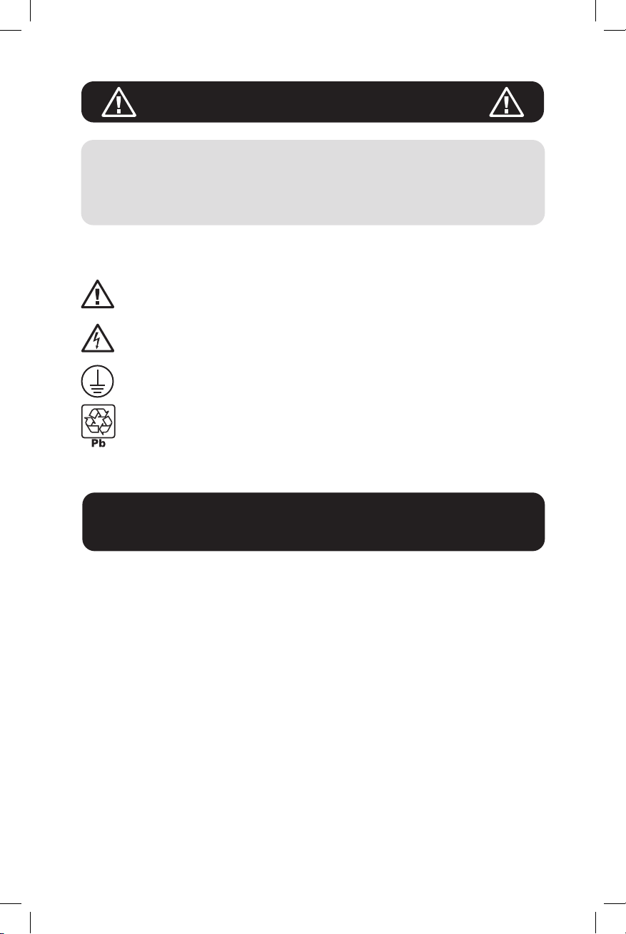
Use a RED wire for the POSITIVE supply.
Use a BLACK wire for the NEGATIVE supply.
Use a GREEN wire for the GROUND wire.
Strip the wires using a
1
wire stripping tool.
Note: The recommended
length for the stripped
ends is ½ inch.
BLACK
RED
1
3
Connector Cable
Assembly Instructions
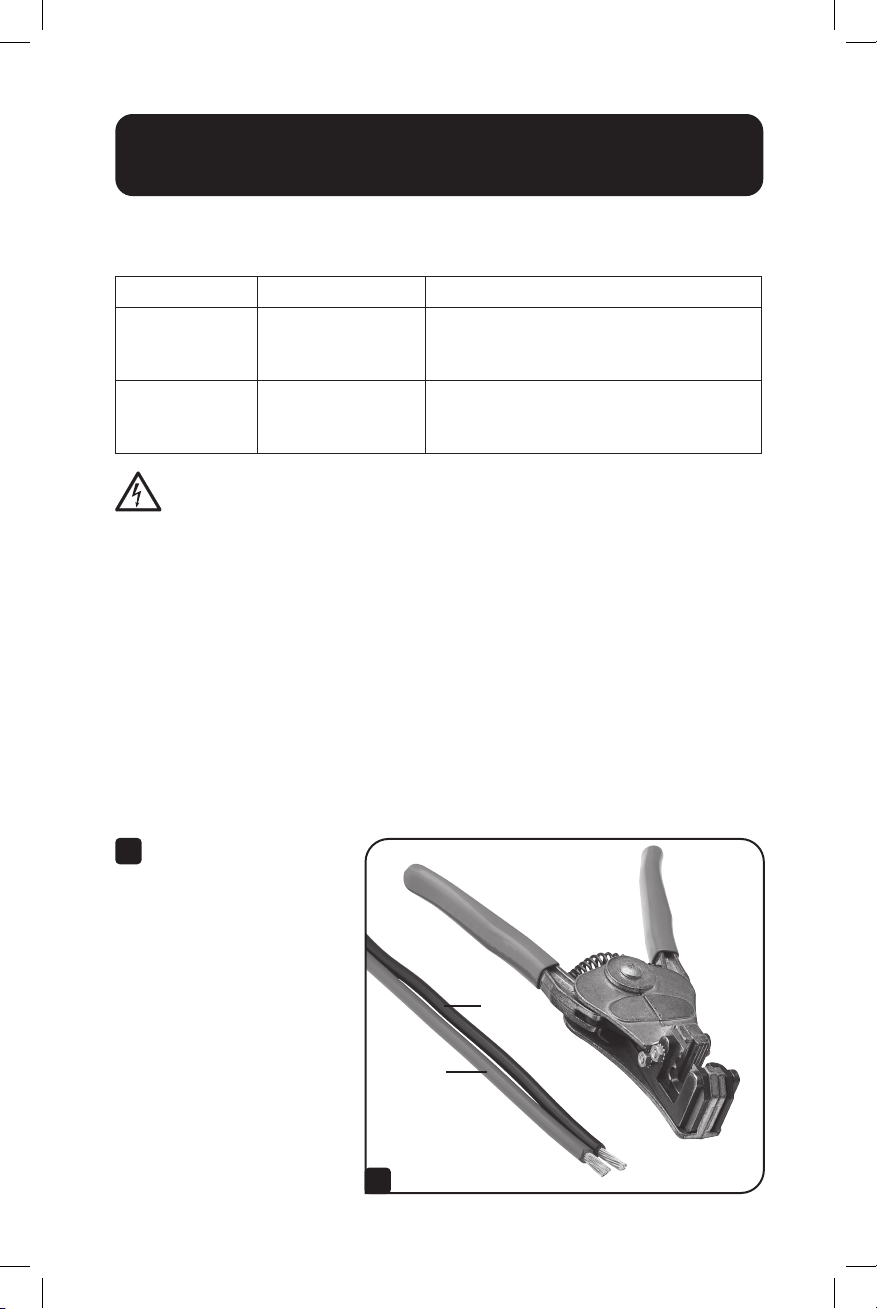
Insert the stripped wire ends into the terminals.
2
2
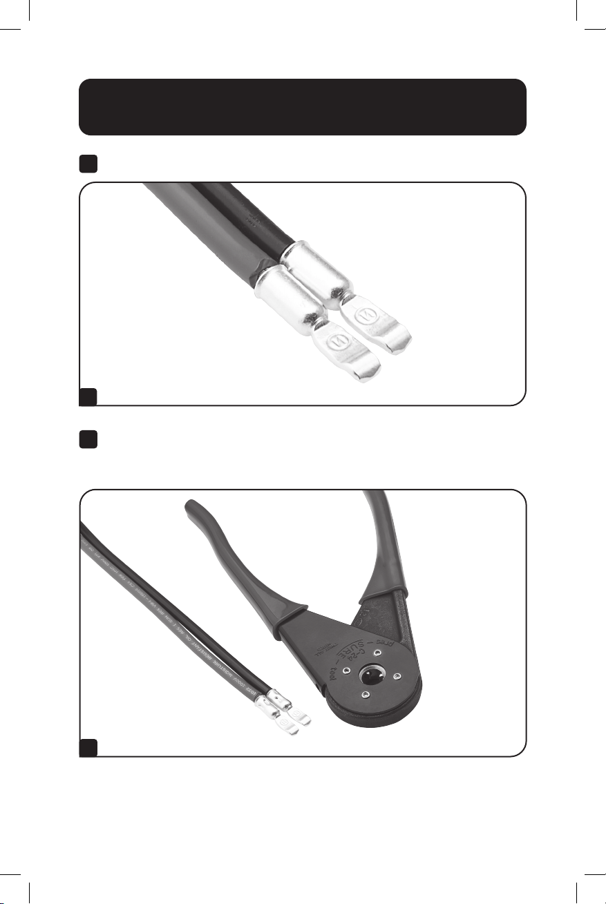
Crimp the terminal and wire with the recommended wire crimping tool.
3
Tug on the wire leads while holding the terminals to ensure the wire is
crimped securely.
3
4

Connector Cable
Assembly Instructions
Insert the RED crimped wire terminal into the RED DC connector
4
housing and the BLACK crimped wire terminal into the BLACK DC
connector housing. Then, join the connector housings together via the
slots on the housings. Be sure to observe the polarity.
BLACK
RED
4
Equipment Connection Warnings
CAUTION: Make sure UPS is powered down and disconnected
from AC mains power. The battery circuitry is not isolated
from AC mains. Turn off power to the UPS prior to battery
connection.
Do not connect or disconnect battery modules while the UPS is operating.
Never attempt to install electrical equipment during a thunderstorm.
Make sure your external battery matches your UPS Rating: 24V or 48V.
External Battery Warnings
Connect the GREEN ground wire between an external metal battery cabinet
and the ground lug on the front of the UPS.
Connect the RED and BLACK cables to the external battery. Be sure to
observe the polarity: RED to the positive terminal and BLACK to the negative
terminal of the external battery.
5
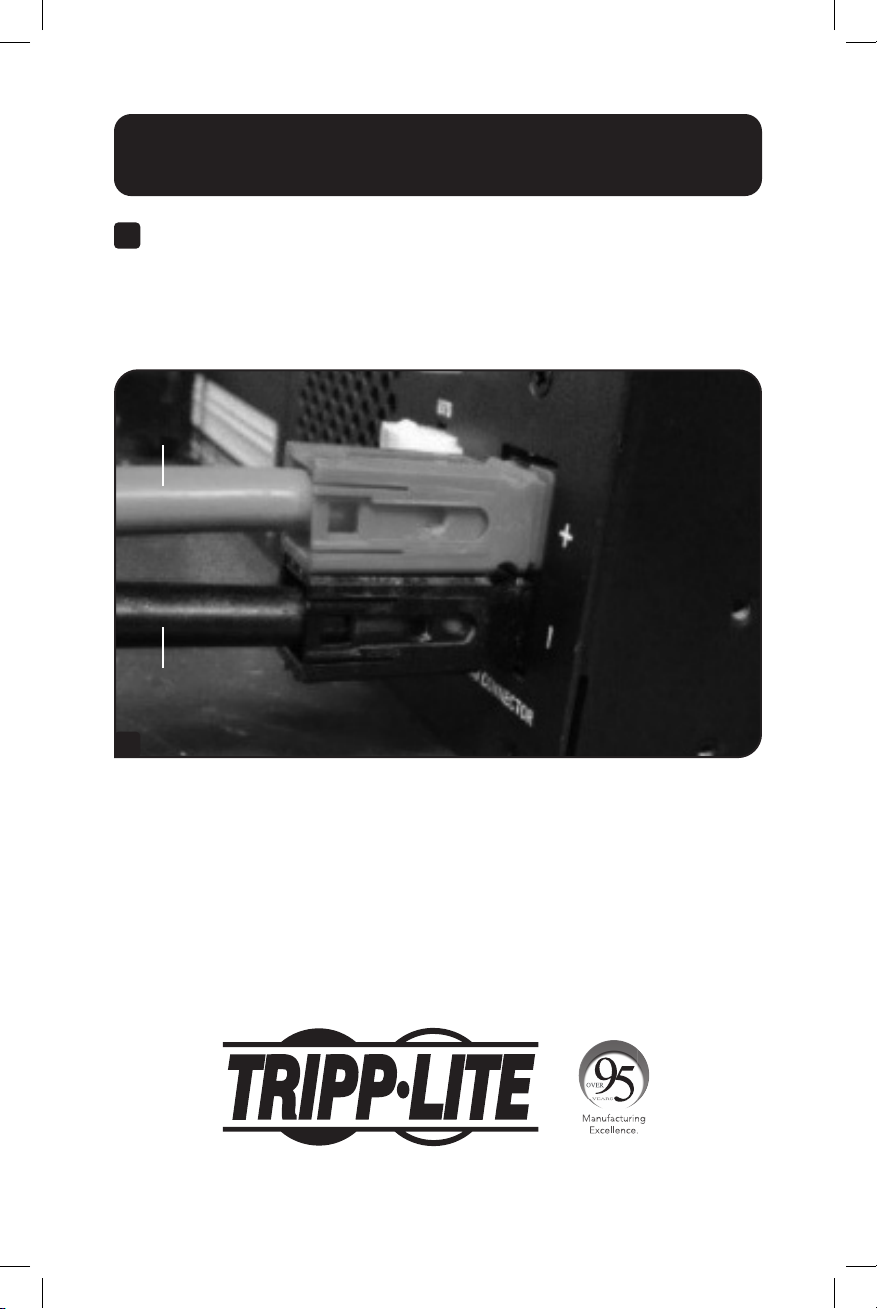
Connector Cable
Assembly Instructions
Once the cable assembly is attached to the external battery at the end
5
opposite the DC connector, it can be mated to the DC connector on the
UPS system’s front panel.
When connecting the cables to the external battery, you may observe
small sparks; this is normal.
RED
BLACK
5
1111 W. 35th Street, Chicago, IL 60609 USA • tripplite.com/support
6
20-02-243 93-3C60_RevB

Hoja de Instrucciones
Conjunto de Cable
Conector de CD de
la Batería Externa
Modelos: SMART1524ET, SMART1548ET
English 1 • Français 13
1111 W. 35th Street, Chicago, IL 60609 EE UU • tripplite.com/support
Copyright © 2020 Tripp Lite. Todos los derechos reservados.
7

Instrucciones de Seguridad Importantes
CONSERVE ESTAS INSTRUCCIONES
Esta hoja anexa contiene instrucciones importantes para el
ensamble correcto y advertencias que deben seguirse. No acatar
estas advertencias de instrucciones puede afectar su seguridad.
Explicación de los Símbolos
Precaución, Riesgo de Daño
Peligro de descarga eléctrica
Tierra Física para Protección
Reciclable, Contiene Plomo
Instrucciones para el Ensamble
del Cable Conector
Con su sistema UPS se incluyen los siguientes accesorios:
Conector (Cant. 1): Gabinete Rojo, Número de Parte de ANEN: PA75B2-HL
Conector (Cant. 1): Gabinete Negro, Número de Parte de ANEN: PA75B0-HL
Terminales (cantidad 2): Número de Parte de ANEN: PA5952-T
Use solamente la herramienta de compresión recomendada (suministrada
por el usuario): Número de parte de Buchanan: C-24
8

Instrucciones para el Ensamble
del Cable Conector
Si no tiene los conectores y terminales, póngase en contacto con Tripp Lite
en tripplite.com/support. Si necesita reemplazos, solicite el kit listado a
continuación:
Modelo de UPS Número de Kit El Kit Incluye:
SMART1524ET BPA7524KIT (x2) Terminales de CD 6 AWG
(x1) Gabinete de Conector de CD Rojo
(x1) Gabinete de conector de CD Negro
SMART1548ET BPA7548KIT (x2) Terminales de CD 8 AWG
(x1) Gabinete de Conector de CD Rojo
(x1) Gabinete de conector de CD Negro
PRECAUCIÓN: El ensamble e instalación deberá llevarse a cabo
solo por personal profesional de servicio eléctrico calificado.
Los cables de CD suministrados por el usuario tienen una longitud máxima
recomendada de 2 m [6.65 pies]. Use únicamente conductores trenzados
de cobre.
Modelo SMART1524ET (Sistema UPS de 24V): Use cable mínimo 6 AWG,
especificado para 105°C [221°F].
Modelo SMART1548ET (Sistema UPS de 48V): Use cable mínimo 8 AWG,
especificado para 105°C [221°F].
Cable de conexión a tierra (ambos modelos): Use cable mínimo 12 AWG,
especificado para 105°C [221°F].
Use un cable ROJO para el suministro POSITIVO.
Use un cable NEGRO para el suministro NEGATIVO.
Use un cable VERDE para el cable de CONEXIÓN A TIERRA.
Pele los cables usando
1
una herramienta de
pelado de cables.
Nota: La longitud
recomendada para los
extremos pelados es de
13 mm [½"].
NEGRO
ROJO
1
9

Instrucciones para el Ensamble
del Cable Conector
Inserte los extremos del cable pelado en las terminales.
2
2
Oprima la terminal y el cable con la herramienta de compresión de
3
cables recomendada. Tuerza la punta de los cables mientras sostiene
las terminales para asegurar que el cable esté prensado firmemente.
3
10

Instrucciones para el Ensamble
del Cable Conector
Inserte la terminal de cable de compresión ROJA en el alojamiento
4
ROJO del conector de CD y la terminal de cable de compresión
negra en el alojamiento NEGRO del conector de CD. Luego, una los
alojamientos del conector a través de las ranuras en los alojamientos.
Asegúrese de observar la polaridad.
NEGRO
ROJO
4
Advertencias en relación con la Conexión del
Equipo
PRECAUCIÓN: Asegúrese de que el UPS esté apagado y
desconectado de la energía de la red pública de CA. El circuito
de la batería no está aislado de la alimentación de CA. Apague
el UPS antes de la conexión de la batería.
No conecte o desconecte los módulos de baterías mientras el UPS esté
funcionando.
Nunca intente instalar equipos eléctricos durante una tormenta eléctrica.
Asegúrese de que su batería externa coincida con la especificación de su
UPS: 24V o 48V.
Advertencias para la Batería Externa
Conecte el cable de tierra VERDE entre un gabinete de baterías metálicas
externas y la terminal de conexión a tierra ubicada en el frente del UPS.
Conecte los cables NEGRO y ROJO a la batería externa. Asegúrese de
observar la polaridad: ROJO a la terminal positiva y NEGRO a la terminal
negativa de la batería externa.
11

Instrucciones para el Ensamble
del Cable Conector
Una vez que el conjunto del cable está acoplado a la batería externa en
5
el extremo opuesto al conector de CD, puede acoplarse al conector de
CD en el panel frontal del sistema UPS.
Al conectar los cables a la batería externa, es posible que observe
pequeñas chispas; esto es normal.
ROJO
NEGRO
5
1111 W. 35th Street, Chicago, IL 60609 EE UU • tripplite.com/support
12
20-02-243 93-3C60_RevB

Feuille d'instruction
Ensemble du câble
du connecteur
CC des batteries
externes
Modèles : SMART1524ET, SMART1548ET
English 1 • Español 7
1111 W. 35th Street, Chicago, IL 60609 USA • tripplite.com/support
Droits d'auteur © 2020 Tripp Lite. Tous droits réservés.
13

Consignes de sécurité importantes
CONSERVER CES INSTRUCTIONS
Cette feuille d'addenda contient des directives importantes pour
assembler l'appareil correctement et des avertissements qui
doivent être respectés. Le non-respect de ces avertissements sur
l'installation pourrait menacer votre sécurité.
Explication des symboles
Mise en garde, risque de danger
Risque de décharges électriques
Mise à la terre de protection
Recyclable, contient du plomb
Câble du connecteur
Instructions d'assemblage
Les accessoires suivants sont inclus avec l'onduleur :
Connecteur (qté 1) : boîtier rouge, numéro de pièce ANEN : PA75B2-HL
Connecteur (qté 1) : boîtier noir, numéro de pièce ANEN : PA75B0-HL
Bornes (qté 2) : numéro de pièces ANEN : PA5952-T
Utiliser uniquement l'outil de sertissage recommandé (fourni par
l'utilisateur) : numéro de pièce Buchanan : C-24
14

Câble du connecteur
Instructions d'assemblage
Contacter Tripp Lite à tripplite.com/support si les connecteurs et les borne
sont manquants. Pour obtenir des remplacements, demander la trousse
mentionnée ci-dessous :
Modèle du
système ASC
SMART1524ET BPA7524KIT (x2) bornes CC 6 AWG
SMART1548ET BPA7548KIT (x2) bornes CC 8 AWG
Numéro de la
trousse La trousse inclut
(x1) boîtier pour connecteur CC rouge
(x1) boîtier pour connecteur CC noir
(x1) boîtier pour connecteur CC rouge
(x1) boîtier pour connecteur CC noir
MISE EN GARDE : L'assemblage et l'installation doivent être
confiés uniquement à du personnel du service électrique
professionnel qualifié.
Les câbles CC fournis par l'utilisateur ont une longueur maximale
recommandée de 2 m (6,65 pi). Utiliser des conducteurs à toron en cuivre
uniquement.
Modèle SMART1524ET (onduleur de 24 V) : utiliser un fil de 6 AWG
minimum, coté pour 105 °C (221 °F).
Modèle SMART1548ET (onduleur de 48 V) : utiliser un fil de 8 AWG
minimum, coté pour 105 °C (221 °F).
Fil de mise à la terre (les deux modèles) : utiliser un fil de 12 AWG
minimum, coté pour 105 °C (221 °F).
Utiliser un fil ROUGE pour l'alimentation POSITIVE.
Utiliser un fil NOIR pour l'alimentation NÉGATIVE.
Utiliser un fil VERT pour le fil DE TERRE.
Dénuder les fils en
1
utilisant un outil à
dénuder.
Remarque : La longueur
recommandée pour les
extrémités dénudées est
12,7 mm (½ pouce).
NOIR
ROUGE
1
15

Câble du connecteur
Instructions d'assemblage
Insérer l'extrémité des fils dénudés dans les bornes.
2
2
Sertir la borne et le fil en utilisant l'outil de sertissage recommandé.
3
Tirer sur les fils conducteurs tout en tenant les bornes pour s'assurer
que le fil est serti solidement en place.
3
16

Câble du connecteur
Instructions d'assemblage
Insérer la borne du fil serti ROUGE dans le boîtier du connecteur
4
CC ROUGE et la borne du fil serti NOIR dans le boîtier du connecteur
CC NOIR. Joindre ensuite les boîtiers de connecteur ensemble via les
fentes sur les boîtiers. S'assurer de respecter la polarité.
NOIR
ROUGE
4
Avertissements liés au branchement de
l'équipement
MISE EN GARDE : S'assurer que l'onduleur est hors tension et
débranché de l'alimentation CA du secteur. La circuiterie de la
batterie n'est pas isolée du secteur CA. Couper l'alimentation
vers l'onduleur avant de connecter la batterie.
Ne pas connecter ou déconnecter les modules de batteries pendant le
fonctionnement de l'onduleur.
Ne jamais essayer d'installer un équipement électrique pendant un orage.
S'assurer que la batterie externe correspond à la valeur nominale de
l'onduleur : 24 V ou 48 V.
Avertissements liés aux batteries externes
Connecter le fil de terre VERT entre une armoire de batteries en métal
externe et la prise de terre à l'avant de l'onduleur.
Connecter les câbles ROUGE et NOIR à la batterie externe. S'assurer de
respecter la polarité : ROUGE pour la borne positive et NOIR pour la borne
négative de la batterie externe.
17

Câble du connecteur
Instructions d'assemblage
Une fois que l'ensemble de câbles est fixé à la batterie externe à
5
l'extrémité opposée du connecteur CC, il peut être accouplé au
connecteur CC sur le panneau avant de l'onduleur.
Au moment de connecter les câbles à la batterie externe, il est normal
que la connexion produise de petites étincelles.
ROUGE
NOIR
5
18

19

1111 W. 35th Street, Chicago, IL 60609 USA • tripplite.com/support
20
20-02-243 93-3C60_RevB
 Loading...