

Trinity TXK-1701 Owner's Manual
OWNER’S MANUAL
TRINITY DOUBLE-SIDED MOBILE BIN RACK
Model # TXK-1701
Everything in its place.
®
© 2016 TRINITY - 800.985.5506
1
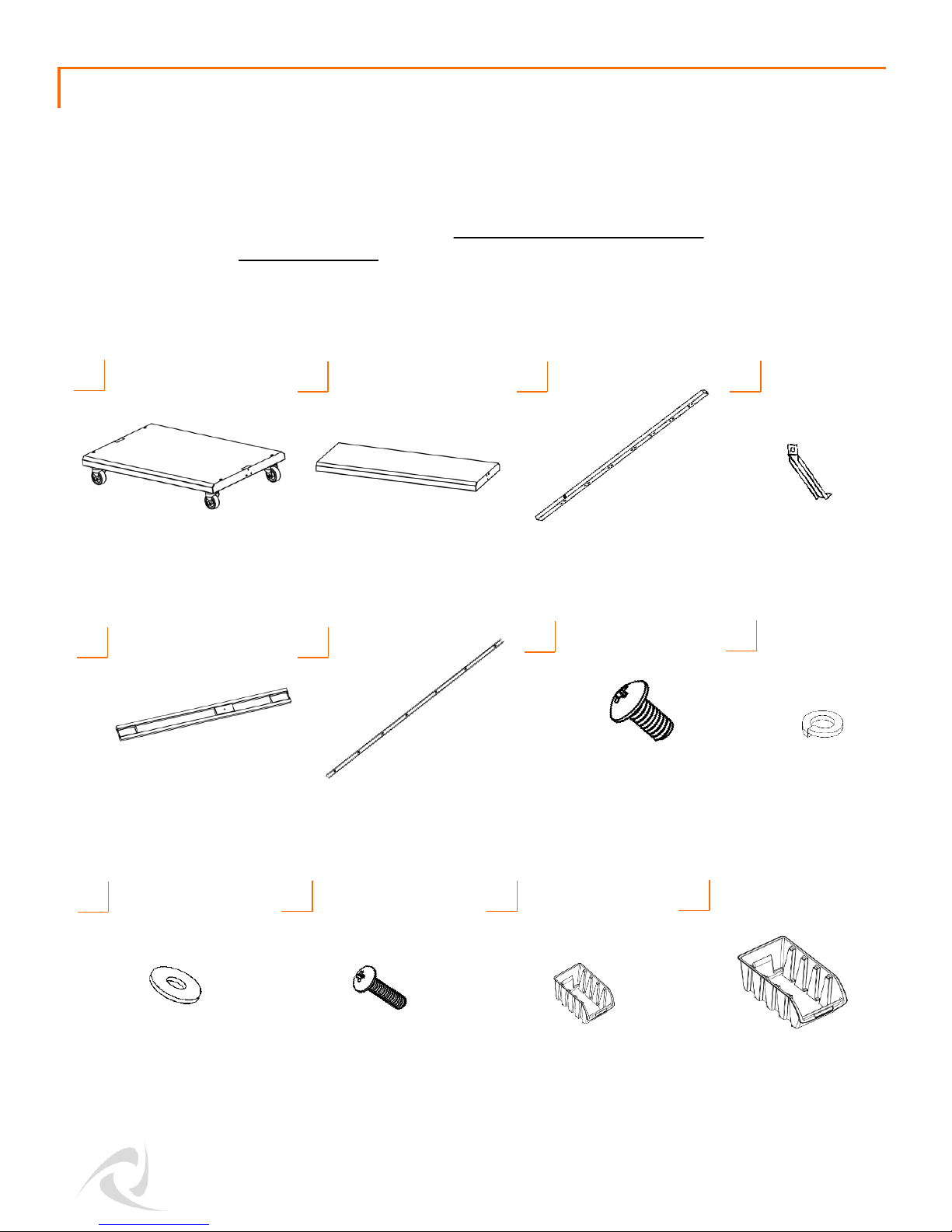
Your TRINITY Double-Sided Mobile Bin Rack should include the following parts. Please inspect
box contents to ensure you have received all components.
If you are missing any parts, need assistance with assembly or have questions, please contact
TRINITY Customer Service: 800.985.5506 or customerservice@trinityii.com. Parts can also be
requested online at www.trinityii.com (Help & More, Contact Us).
A Phillips head screwdriver is required.
BOTTOM SHELF (1)
w/ CASTERS
A
TOP SHELF (1)
B C
HANGING BAR
SUPPORT (1)
G
E
POST (2)
W/ SCREWS
LARGE
SCREW (20)
F
HANGING BAR (7)
PARTS LIST
D
POST SUPPORT (4)
H
SPLIT
WASHER (20)
I
FLAT
WASHER (20)
J
SMALL
SCREW (7)
K
SMALL BIN (64)
L
MEDIUM BIN (30)

© 2016 TRINITY - 800.985.5506
2
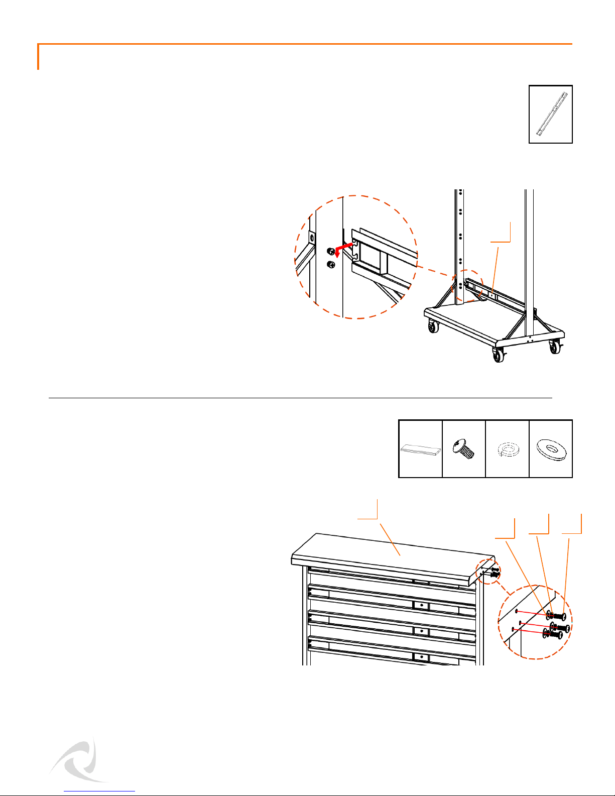
ASSEMBLY INSTRUCTIONS
Secure a diagonal POST SUPPORT(D)
to each side of the POSTS (C) with the
LARGE SCREWS (G), SPLIT
WASHERS (H) and FLAT WASHERS (I).
Screw one end of each diagonal POST
SUPPORT (D) into the POST (C) and the
other end into the BOTTOM SHELF (A).
Insert both POSTS (C) into the BOTTOM
SHELF (A). Make sure that the screws on
the POSTS (C) are facing INWARD, and
that the “UP” sticker end of the POST (C)
is at the top. Line up the nuts on the
POSTS (C) with the holes on the side of
the BOTTOM SHELF (A). Insert a LARGE
SCREW (G) through SPLIT WASHER (H)
then FLAT WASHER (I) and hand fasten
to nut on the POSTS (C). Loosely secure
both POSTS (C). Do NOT tighten
completely until STEP 4.
STEP 1
STEP 2
H (6) I (6)
C (2)
C
A
A (1)
D
G
I
G (6)
H
D (4)
H (8) I (8)
G (8)
G
I
H
Phillips
© 2016 TRINITY - 800.985.5506
3
ASSEMBLY INSTRUCTIONS
Loosen the screws on the inside of both
POSTS (C) so that the HANGING
BARS (E) can be inserted. Starting with
the lowest BAR (E), insert all BARS (E)
in the same direction.
The "L" (left) stickers on the HANGING
BARS (E) indicate proper positioning
so that the HANGING BAR SUPPORT
(F) can be properly installed in Step 5.
Slide the HANGING BARS (E) in, and
then down as shown. Tighten the
screws on both POSTS (C).
STEP 3
E (7)
E
Slide the TOP SHELF (B) onto the top of
both POSTS (C) and secure it with the
LARGE SCREWS (G), SPLIT
WASHERS (H) and FLAT WASHERS (I)
on both sides.
Tighten all LARGE SCREWS (C),
including LARGE SCREWS (C) at the
bottom of POSTS (C) from STEP 1.
STEP 4
B (1)
H (6) I (6)
G (6)
B
G
I
H
 Loading...