

Trinity Tx51, Tx151, Tx81, Tx151(C), Tx101 Installation And Operation Instructions Manual
Trinity Tx
Model Numbers: Tx 51 - 151
Version Date: 2013-12-30
INSTALLATION AND OPERATION INSTRUCTIONS FOR
TRINITY Tx BOILER
TABLE OF CONTENTS
HAZARD SYMBOLS AND DEFINITIONS
Danger Sign: Indicates a hazardous situation which, if not avoided, will
result in serious injury or death.
Warning Sign: Indicates a hazardous situation which, if not avoided,
could result in serious injury or death.
Caution Sign plus Safety Alert Symbol: Indicates a hazardous situation
which, if not avoided, could result in minor or moderate injury.
Caution Sign without Safety Alert Symbol: Indicates a hazardous
situation which, if not avoided, could result in property damage.
Notice Sign: Indicates a hazardous situation which, if not avoided,
could result in property damage.
This Boiler must be installed by a licensed and trained Heating
Technician or the Warranty is Void. Failure to properly install this
unit may result in property damage, serious injury to occupants, or possibly death.
NEW PRODUCT LINE
High Efficiency
Condensing Gas Boiler
H
NTI # 84874
2
Trinity Tx │Installation and Operation Instructions Tx Series
Read Before Proceeding
If you do not follow these instructions exactly, a fire or explosion may result causing
property damage, serious injury or death.
FOR YOUR SAFETY, READ BEFORE OPERATING_
A) This boiler does not have a pilot. It is equipped with an ignition device which automatically lights the
burner. Do not try to light the burner by hand.
B) BEFORE OPERATING smell all around the boiler area for gas. Be sure to smell next to the floor
because some gas is heavier than air and will settle on the floor.
WHAT TO DO IF YOU SMELL GAS:
• Do not try to light any boiler.
• Do not touch any electric switch.
• Do not use any phone in your building.
• Immediately call your gas supplier from a neighbor's phone. Follow the gas supplier's instructions.
• If you cannot reach your gas supplier, call the fire department.
C) Use only your hand to turn the gas “shutoff” valve. Never use tools. If the handle will not turn by hand,
don't try to repair it, call a qualified service technician. Force or attempted repair may result in a fire or
explosion.
D) Do not use this boiler if any part has been under water. Immediately call a qualified service technician
to inspect the boiler and to replace any part of the control system and any gas control which has been
under water.
OPERATING INSTRUCTIONS_
1. STOP! Read the safety information above very carefully.
2. Set the thermostat to lowest setting. Turn off all electric power to the boiler.
3. This boiler does not have a pilot. It is equipped with an ignition device which automatically lights the
burner. Do not try to light the burner by hand.
4. Turn the manual gas valve to the OFF position. Remove front access panel.
5. Wait five (5) minutes to clear out any gas. Then smell for gas, including near the floor. If you smell gas,
STOP! Follow “B” in the safety information above. If you don't smell gas, go to the next step.
6. Turn the manual gas valve ON. Wait an additional five (5) minutes smelling for gas.
7. Replace the front access panel.
8. Set thermostat to highest setting. Turn on all electric power to the boiler.
9. Ignition sequence is automatic. Combustion will occur after a brief fan purge.
10. If ignition does not occur, follow the instructions “To Turn Off Gas To Boiler” and call your service
technician or gas supplier.
TO TURN OFF GAS TO THE BOILER_
1. STOP! Read the safety information above very carefully.
2. Turn off all electric power to the boiler.
3. Turn the manual gas valve to the OFF position.
Crystalline Silica - Certain components confined in the combustion chamber may
contain this potential carcinogen. Improper installation, adjustment, alteration, service or
maintenance can cause property damage, serious injury (exposure to hazardous materials) or death. Refer to
Section 15.0 for information on handling instructions and recommended personal protective equipment.
Installation and service must be performed by a qualified installer, service agency or the gas supplier (who must
read and follow the supplied instructions before installing, servicing, or removing this boiler. This boiler
contains materials that have been identified as carcinogenic, or possibly carcinogenic, to humans).
Void Warranty - This Boiler must have water flowing through it whenever the burner is
on or it will damage the unit and void the warranty. Failure to follow these instructions
may result in serious injury or death.
Tx Series Installation and Operation Instructions │Trinity Tx
3
Energy Saving Feature - This boiler is equipped with a feature that saves energy by
reducing the boiler water temperature as the heating load decreases. This feature is
equipped with an override which is provided primarily to permit the use of an external energy management
system that serves the same function. THIS OVERRIDE MUST NOT BE USED UNLESS AT LEAST ONE
OF THE FOLLOWING CONDITIONS IS TRUE :
An external energy management system is installed that reduces the boiler water temperature as the heating
load decreases.
This boiler is not used for any space heating.
This boiler is part of a modular or multiple boiler system having a total input of 300,000 BTU/hr or greater.
This boiler is equipped with a tankless coil.
1.0 INTRODUCTION
General Installation Requirements
The installation of your NTI Trinity Tx gas boiler must conform to the requirements of this manual, your local
authority, and the National Fuel Gas Code ANSI Z223.1 and or CAN/CGA B149 Installation Codes. Where
required by the Authority, the installation must conform to the standard for “Controls and Safety Devices for
Automatically Fired Boilers ANSI/ASME CSD-1.
This document pertains to the correct installation and operation of NTI Trinity boiler model Tx. The instructions
detailed in this document supersede any and all previous instructions provided by NTI, written or otherwise.
Each unit is provided with the following:
1. Installation and Operating Instructions,
2. Trinity Users’ Manual, and
3. Natural Gas to LP Conversion Kit*
* The conversion kit is required to convert the boiler so it will safely operate with Propane Gas.
Read and understand this entire document prior to proceeding with the installation of the
Trinity Tx. Failure to follow the instructions outlined in this document will result in
property damage, serious injury or death.
User Responsibilities
This boiler must be installed and serviced by a qualified installer or service technician. This boiler must be
serviced and inspected annually when operating in normal residential applications. Demanding applications or
extreme conditions (i.e. when operating with LP-Propane) may require more frequent service and inspection. As
the User/Owner of this equipment, you are responsible for ensuring the maintenance is performed at the required
intervals (see Section 14 – Annual Maintenance and Inspection).
Failure to have the boiler properly serviced and inspected on a regular basis by a qualified
service technician may result in property damage, serious injury or death.
Failure to keep the Vent and Combustion Air Intake clear of ice, snow, and other debris
may result in property damage, serious injury, or death.
Installer Responsibilities
As the installing technician it is your responsibility to ensure the installation is performed in accordance with this
instruction manual as well as any applicable local or National installation codes. It is also your responsibility to
inform the User/Owner of their obligation with respect to the above description under “User Responsibilities”.
Failure to follow this warning could result in fire, serious injury, or death.
4
Trinity Tx │Installation and Operation Instructions Tx Series
Failure to use the appropriate Natural to LP Conversion Kit and Orifice when operating
the Trinity Tx to operate with Propane will result in extremely dangerous burner
operation leading to property damage, serious injury or death. Refer to section titled ATTENTION:
LIQUEFIED PETROLEUM (LP) PROPANE for applicable conversion kit and LP orifice numbers.
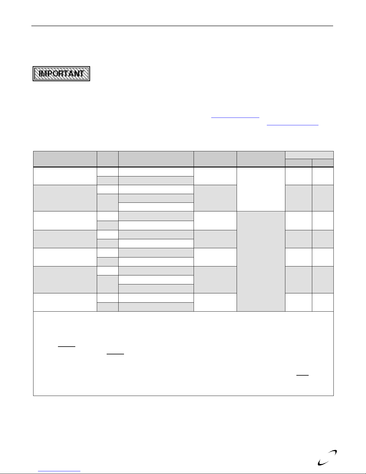
ATTENTION: LIQUEFIED PETROLEUM (LP) PROPANE
The Trinity Tx is factory set to operate with Natural Gas. BEFORE OPERATING WITH PROPANE, the
specified LP Conversion Kit and Orifice must be installed to convert the boiler so it will operate safely with
LP Propane. The correct kit and LP orifice is listed below (Each kit comes with conversion instructions).
Liquefied Petroleum (LP) propane gas is heavier than air; therefore, it is imperative that your Trinity Tx boiler
is not installed in a pit or similar location that will permit heavier than air gas to collect. Local Codes may
require boilers fueled with LP gas be provided with an approved means of removing unburned gases from the
room. Check your local codes for this requirement.
Natural to LP Propane Conversion Kit_
Model Number Kit Number LP Orifice
Tx51 84867-1 3.5mm
Tx81 84867-2 3.8mm
Tx101 84867-3 4.2mm
Tx151(C) 84867-4 5.05mm
Boiler Vent / Air-Inlet Piping
The Trinity Tx is certified as a “Category IV” boiler, and requires a “Special Venting
System” designed for pressurized venting. The exhaust gases must be piped directly to
the outdoors using the vent materials and rules outlined in these instructions. Failure to follow these instructions
will result in serious injury or death.
5
IN THE STATE OF MASSACHUSETTS ONLY
(a) For all horizontally vented gas fueled equipment installed in every dwelling, building or structure used in whole or
in part for residential purposes, including those owned and operated by the Commonwealth and where the side wall
exhaust vent termination is less than seven (7) feet above finished grade in the area of the venting, including but not
limited to decks and porches, the following requirements shall be satisfied:
1. INSTALLATION OF CARBON MONOXIDE DETECTORS At the time of installation of the side wall
horizontal vented gas fueled equipment, the installing plumber or gas fitter shall observe that a hard wired
carbon monoxide detector with an alarm and battery back-up is installed on the floor level where the gas
equipment is to be installed and on each additional level of the dwelling, building or structure served by the
equipment. It shall be the responsibility of the property owner to secure the services of qualified licensed
professionals for the installation of hard wired carbon monoxide detectors.
a. In the event that the side wall horizontally vented gas fueled equipment is installed in a crawl space or an
attic, the hard wired carbon monoxide detector with alarm and battery back-up may be installed on the next
adjacent floor level.
b. In the event that the requirements of this subdivision cannot be met at the time of completion of
installation, the owner shall have a period of 30 days to comply with the above requirements; provided,
however, that during said 30 day period a battery operated carbon monoxide detector with an alarm shall
be installed.
2. APPROVED CARBON MONOXIDE DETECTORS Each carbon monoxide detector as required in accordance
with the above provisions shall comply with NFPA 720 and be ANSI/UL 2034 listed and IAS certified.
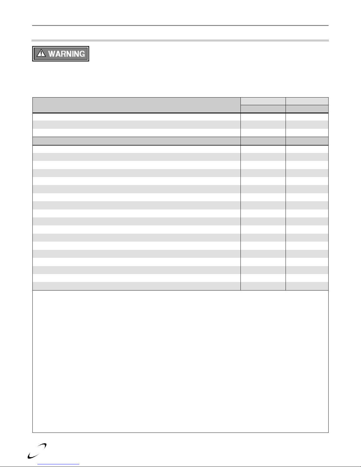
3. SIGNAGE A metal or plastic identification plate shall be permanently mounted to the exterior of the building
at a minimum height of eight (8) feet above grade directly in line with the exhaust vent terminal for the
horizontally vented gas fueled heating boiler or equipment. The sign shall read, in print size no less than onehalf (1/2) inch in size, “GAS VENT DIRECTLY BELOW. KEEP CLEAR OF ALL OBSTRUCTIONS”
(plate included with boiler).
4. INSPECTION The state or local gas inspector of the side wall horizontally vented gas fueled equipment shall
not approve the installation unless, upon inspection, the inspector observes carbon monoxide detectors and
signage installed in accordance with the provisions of 248 CMR 5.08(2)(a)1 through 4.
(b) EXEMPTIONS: The following equipment is exempt from 248 CMR 5.08(2)(a)1 through 4:
1. The equipment listed in Chapter 10 entitled “Equipment Not Required To Be Vented” in the most current
edition of NFPA 54 as adopted by the Board; and
2. Product Approved side wall horizontally vented gas fueled equipment installed in a room or structure separate
from the dwelling, building or structure used in whole or in part for residential purposes.
(c) MANUFACTURER REQUIREMENTS – GAS EQUIPMENT VENTING SYSTEM PROVIDED: When the
manufacturer of Product Approved side wall horizontally vented gas equipment provides a venting system design or
venting system components with the equipment, the instructions provided by the manufacturer for installation of the
equipment and the venting system shall include:
1. Detailed instructions for installation of the venting system design or the venting system components; and
2. A complete parts list for the venting system design or venting system.
(d) MANUFACTURER REQUIREMENTS – GAS EQUIPMENT VENTING SYSTEM NOT PROVIDED:
When the manufacturer of a Product Approved side wall horizontally vented gas fueled equipment does not provide
the parts for venting the flue gases, but identifies “special venting systems”, the following requirements shall be
satisfied by the manufacturer:
1. The referenced “special venting system” instructions shall be included with the appliance or equipment
installation instructions; and
2. The “special venting system” shall be Product Approved by the Board, and the instructions for that system shall
include a parts list and detailed installation instructions.
(e) A copy of all installation instructions for all Product Approved side wall horizontally vented gas fueled equipment,
all venting instructions, all parts list for venting instructions, and/or all venting design instructions shall remain with
the appliance or equipment at the completion of the installation.
Tx Series Installation and Operation Instructions │Trinity Tx
6
DESCRIPTION
Tx51
Tx81
Tx101
Tx151
Tx151C
CSA Input Modulation
1
[MBH]
9.2-46
16.4-82
20.2-101
30.2-151
30.2-151
DOE Heating Capacity
1,2
[MBH]
42
75
92
138
138
Net I=B=R Rating
1,2
[MBH]
36
65
80
120
120
DOE AFUE2 [%]
93.1
Water Connections – NPT [in.]
1
3/4
Gas Connection - NPT, in.
½
Vent/Air-inlet Pipe Diameter
[in.] 3
2 or 3
Dimensions H x W x D [in.]
31-1/4 x 18 x 16
Approx. Boiler Weight
with Water [lbs.]
77
79
86
87
98
Approx. Boiler Water Content
[Gallons]
0.5
0.6
0.7
0.8
1
Electrical Rating
120V/1Ph/60Hz/less than 12A
Notes:
1
Listed Input and Output ratings are at minimum vent lengths at an altitude of 0-2000ft. Numbers will be lower with
longer venting and/or altitudes greater than 2000ft.
2
Ratings based on standard test procedures prescribed by the U.S. Department of Energy.
3
Trinity Tx requires a special venting system, use only vent materials and methods detailed in these instructions.
Elevations
2001 ft [610 m]
3000 ft [914 m]
4000 ft [1219 m]
4500 ft [1372 m]
5000 ft [1524 m]
In Canada 1
de-rate by 10%
de-rate by 10%
de-rate by 10%
de-rate by 10%
de-rate % may vary
In USA 2
-
de-rate by 4%
de-rate by 8%
de-rate by 8%
de-rate by 12%
Notes:
1
Canada: Altitudes between 2000-4500 ft [610-1372 m], de-rate by 10%. Consult local authorities for de-rating
capacities for altitudes above 4500 ft [1372 m].
2
USA: De-rate capacity by 4% for every 1000 ft [305 m] over 2000 ft [610 m].
Trinity Tx │Installation and Operation Instructions Tx Series
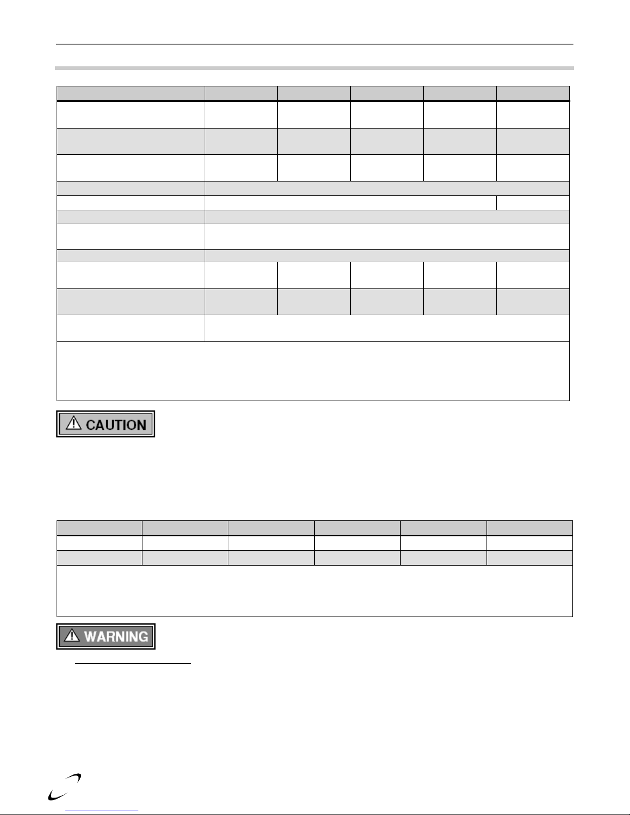
2.0 SPECIFICATIONS
Table 2-1 Trinity Tx Specifications
Wall mounting of unit requires two people to lift the boiler into place. Failure to follow
these instructions may result in property damage or personal injury.
High Altitude Operation
The Trinity is designed to operate at its maximum listed capacity in installations located at 0-2000ft above Sea
Level. Since the density of air decreases as elevation increases, maximum specified capacity should be de-rated
for elevations above 2000 ft [610 m] in accordance with Table 2-2.
Table 2-2 De-rate % for High Altitudes
Combustion – At elevations above 2000 feet, the combustion of the boiler must be
checked with a calibrated combustion analyzer to ensure safe and reliable operation. It is
the Installers responsibility to check the combustion and to adjust the combustion in accordance with
Section 9.0. Failure to follow these instructions may result in property damage, serious injury, or death.
7
Model No.
Clearances
Dimensions - inches [mm]
Front
Top
Sides
Back
Bottom
Flue Pipe
Trinity Tx
Minimum
24 [610] 1
12 [305]
4 [102]
0
9 [229]
1 [25]
Recommended
36 [914]
24 [610]
12 [305]
0
24 [610]
1 [25]
Notes:
1
6” if surface is removable allowing a minimum of 24” [610 mm] clearance (i.e. closet installation). See Ventilation Air
Opening dimensions in Figure 3-1.
Tx Series Installation and Operation Instructions │Trinity Tx
3.0 BOILER LOCATION
In all cases, the Trinity Tx must be installed indoors in a dry location where the ambient temperature must be
maintained above freezing and below 100F [38C]. All boiler components must be protected from dripping,
spraying water, or rain during operation and servicing. Consider the proximity of system piping, gas and
electrical supply, condensate disposal drain, and proximity to vent termination when determining the best boiler
location.
Boiler Area Ventilation Air Openings
If boiler area clearances are less than the recommended clearances specified in Table 3-1, the boiler area must be
ventilated (Exception: if the boiler area/room has a volume of 150 ft3 or greater, ventilation of the boiler room is
not required). Each ventilation air opening must meet the minimum requirements of 1 in2 per 1000 Btu/hr, but
not less than 100 in2. The lower ventilation opening must be located within 6” of the floor while the upper
opening must be located 6” from the top of the space.
approved CPVC, Polypropylene or Stainless Steel vent pipe and fittings can be used. See Table 4-4 for a list of
approved materials. Under all circumstances, the minimum clearances listed in Table 3-1 must be provided.
Closet Installations
For closet installations it is necessary to provide two ventilation air openings as shown in Figure 3-1, each
providing a minimum area equal to 1 in2 per 1000 Btu/hr, but not less than 100 in2 and within 6” of the top and
bottom of the closet door. See Table 3-1 for minimum clearances.
Alcove Installations
Alcove installations have the same minimum clearances as closet installations, except the front must be
completely open to the room at a distance no greater than 18” [457 mm] from the front of the boiler and the
room is at least three (3) times the size of the alcove. Provided these conditions are met, the boiler requires no
extra ventilation air openings to the space. See Table 3-1for minimum clearances.
Residential Garage Installations
When installed in a residential garage, mount the boiler a minimum of 18” [457 mm] above the floor. Locate or
protect the boiler so it cannot be damaged by a moving vehicle. Check with your local authorities for other
possible regulations pertaining to the installation of a boiler in a garage.
Wall Mounting Installations
The Tx is provided with integrated wall mounting brackets. Refer to Figure 3-2 for instructions and illustrations
on wall mounting.
Table 3-1 Minimum Clearances for Installation and Service
Water or flood damaged components must be replaced immediately with new factory-
approved components as failure to do so may result in fire, serious injury, or death.
If the "Boiler Area" does not meet the recommended clearances listed in Table 3-1, and if
the boiler area has a volume less than 150 ft3, it is considered a Closet or Alcove. In US /
Canada, PVC vent pipe and fittings shall not be used within the closet or alcove; only
Closet/alcove installations in US and Canada require approved CPVC, Polypropylene or
Stainless Steel vent and air-inlet pipe and fittings (see Table 4-4); PVC is not permitted.
Failure to follow these instructions may result in damage or serious injury.
8
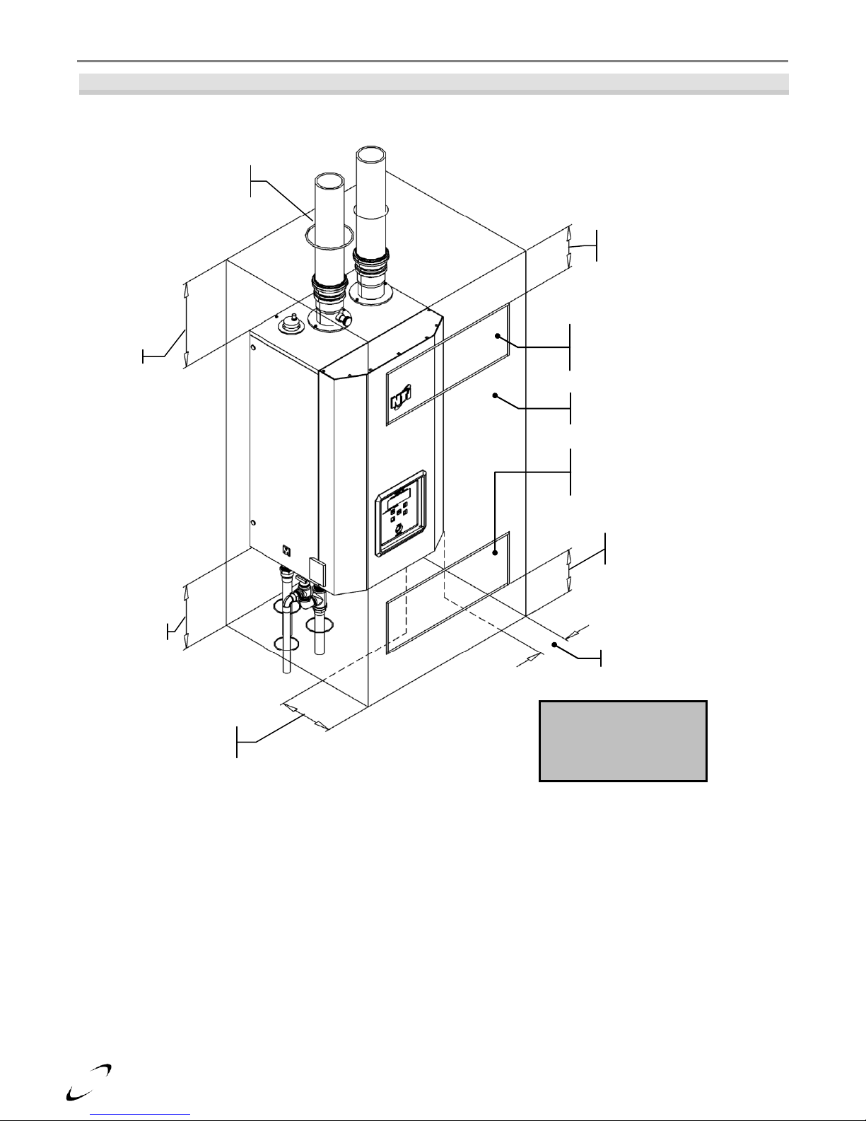
Figure 3-1 Closet Installation, Minimum Clearances
(Non-Combi Model Shown)
Ventilation Air Openings
are not required if the
boiler area meets the
Recommended Clearances
listed in Table 3-1.
Bottom ventilation opening
Max. 6” above floor / bottom
Top ventilation opening
Max. 6” below ceiling / top
Sides = 4”
Front = 6”
(if removable)
Removable surface /
closet door
Ventilation air opening
1in2 per 1000 Btu/hr,
min. 100in
2
Ventilation air opening
1in2 per 1000 Btu/hr,
min. 100in
2
Min. 1” clearance for hot
water and vent pipes
Bottom = 9”
Top = 12”
Trinity Tx │Installation and Operation Instructions Tx Series

9
Figure 3-2 Wall Mounting Instructions
Leave the Top Wall-mount Bracket (A) intact
and remove the Bottom Wall-mount Bracket
(B) that is attached to the bottom-back of the
appliance. Save mounting hardware for Step 4.
Secure Bottom Bracket (B), removed from the
bottom back of the boiler in Step 1, to a solid
wall using field supplied lag screws (anchors
when mounting to a concrete wall) that are
adequate to support the weight of the appliance
(refer to Table 2-1 Specifications). Ensure the
bracket is level and flush to the wall. Mounting
holes to be on the bottom with flange pointed
upward and angled away from the wall.
Mount the appliance to the wall by aligning the
two wall mount brackets, Top Bracket (A)
with the Bottom bracket (B). Slide the top
bracket fastened to the boiler down over the
wall-mounted bracket until it hooks.
Once the appliance is resting securely on the
wall, attach the L-shaped Bracket (C) to the
underside of the appliance using the mounting
hardware removed in Step 1. Next anchor the
L-shaped Bracket (C) to the wall as shown
using field supplied hardware.
Failure to follow instructions may
result in fire, serious injury, or death.
This unit requires two people to lift it
or damage and injury may result.
Top Bracket (A)
Bottom
Bracket (B)
Bottom
Bracket (B)
L-shaped Bracket (C)
shipped with boiler kit box
Wall
Boiler
Ensure Bracket
(A) fully inserts
into Bracket (B)
(B)
(A)
Tx Series Installation and Operation Instructions │Trinity Tx
10
Trinity Tx │Installation and Operation Instructions Tx Series
4.0 GENERAL VENTING
The Trinity Tx is certified as a “Category IV” boiler requiring a “Special Venting System” designed for
pressurized venting. The Exhaust Vent must be piped to the outdoors, using the vent materials and rules outlined
in this section. Under no conditions may this unit vent gases into a masonry chimney, unless it is vacant, and
utilizes the approved venting material and rules described in this section.
Direct Vent Installation (Best Practice)
When installed as a Direct Vent boiler the combustion air-inlet must also be piped directly to the outdoors using
the methods described in this section and in accordance with the National Fuel Gas Code, ANSI Z223.1 (U.S.) or
CSA B149.1 (Canada) and local requirements.
Installation Using Indoor Combustion Air
When the installation uses Indoor Combustion Air (i.e. piping is not directly connecting the appliance air-inlet
fitting to the outdoors), the combustion air-inlet is drawn from Indoors or Outdoors via the appliance area using
the methods described in this section and in accordance with the National Fuel Gas Code, ANSI Z223.1 (U.S.) or
CSA B149.1 (Canada) and local requirements.
appliances may result in personal injury or death.
Indoor Combustion Air - Opening Size and Location: The methods detailed below for determining Opening
Size and Location for accessing indoor combustion air, shall be used when the air infiltration rate is adequate, i.e.
greater than 0.4 ACH (air changes per hour) and when the boiler area and communicating spaces have a
minimum volume of 50 cubic ft per 1000 Btu/hr. If the air infiltration rate is known to be less that 0.4 ACH,
refer to the National Fuel Gas Code for further guidance.
1. Combined spaces on the same story – Each opening shall have a minimum free area of 1 in.2/1000 Btu/hr
of the total input rating of all appliances in the space, but not less than 100 in.2. One opening shall
commence within 12 in. of the top, and one opening shall commence within 12 in. of the bottom, of the
enclosure, see Figure 4-1a. The minimum dimension of air openings shall be not less than 3in.
2. Combined spaces in different stories – The volumes of spaces in different stories shall be considered as
communicating spaces where such spaces are connected by one or more openings in doors or floors having a
total minimum free area of 2 in.2/1000 Btu/hr of total input rating of all appliances.
Outdoor Combustion Air – Opening Size and Location: Outdoor combustion air shall be provided through
opening(s) to the outdoors in accordance with the methods detailed below. The minimum dimension of air
openings shall not be less than 3in.
1. Two Permanent Openings Method – Two permanent openings, one commencing within 12in. of the top,
and one commencing within 12in. of the bottom of the enclosure, shall be provided. The openings shall
communicate directly, or by ducts, with the outdoors or spaces that freely communicate with the outdoors, as
follows:
a. Where communicating with the outdoors or where communicating to the outdoors through vertical ducts,
each opening shall have a minimum free area of 1 in.2/4000 Btu/hr of total input rating of all appliances
in the enclosure; see Figures 4-1b and 4-1c.
b. Where communicating with the outdoors through horizontal ducts, each opening shall have a minimum
free area of 1 in.2/2000 Btu/hr of total input rating of all appliances in the enclosure; see Figure 4-1d.
Vent and Air-inlet are to be piped separately. The Trinity Tx cannot share a common vent
or air-inlet with multiple boilers. Failure to comply will result in serious injury or death.
The boiler shall be located so as not to interfere with proper circulation of combustion,
ventilation, and dilution air.
Make up air requirements for the operation of exhaust fans, kitchen ventilation systems,
clothes dryers, and fireplaces shall be considered in determining the adequacy of a space
to provide combustion air requirements. Failure to ensure adequate make up air to all
11
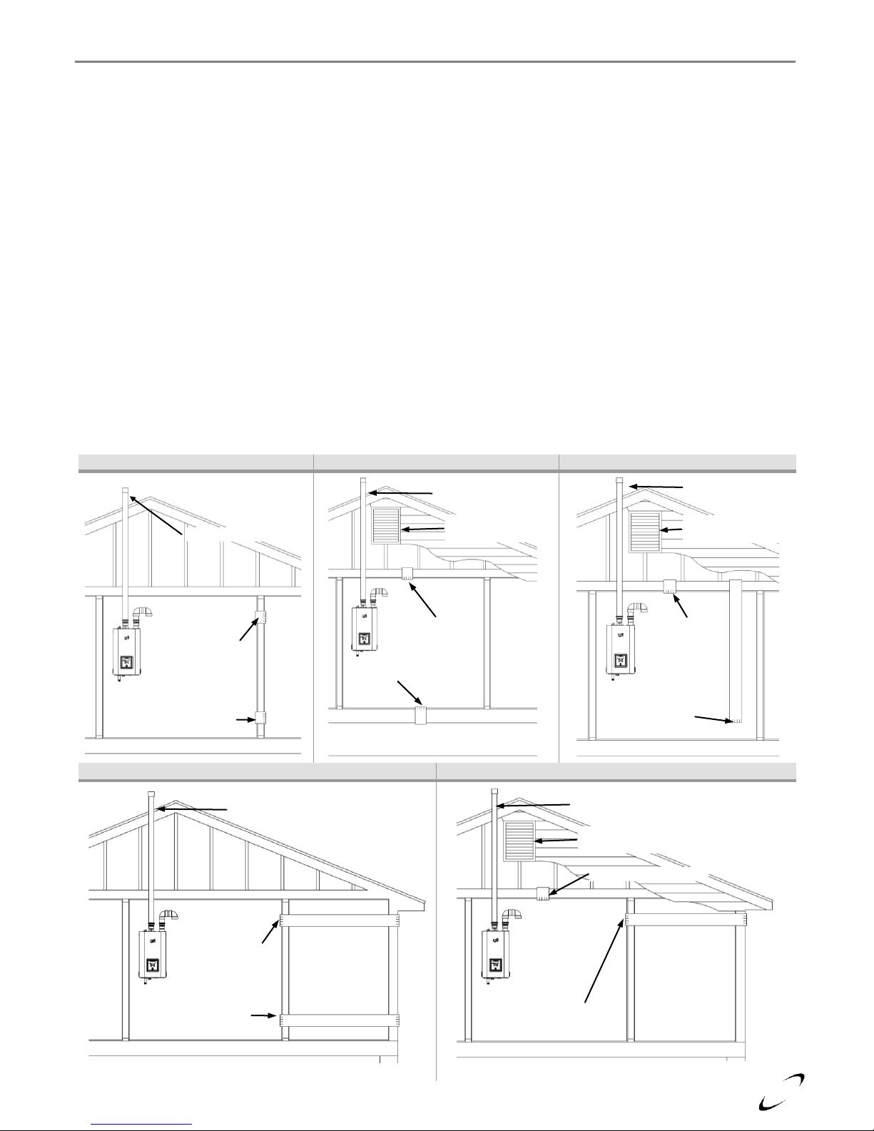
Figure 4-1(a) Indoor Air
Figure 4-1(b) Two Vertical Ducts
Figure 4-1(c) Two Vertical Ducts
Figure 4-1(d) Two Horizontal Ducts
Figure 4-1(e) One Duct Options
Opening (within
1ft of ceiling)
Opening (within
1ft of floor)
Exhaust Vent
Opening
Opening
Exhaust Vent
Ventilation Louvers
(each end of attic)
Ventilated & unheated
crawl space
Exhaust Vent
Ventilation Louvers
(each end of attic)
Opening
Opening (duct
extended to within
1ft of floor)
Exhaust Vent
Opening (within
1ft of ceiling)
Opening (within
1ft of floor)
Exhaust Vent
Ventilation Louvers
(each end of attic)
Opening Option B
(within 1ft of ceiling)
Opening Option A
Tx Series Installation and Operation Instructions │Trinity Tx
2. One Permanent Opening Method – One permanent opening, commencing within 12 in. of the top of the
enclosure, shall be provided. The appliance shall have clearances of at least 1 in. from the sides and back
and 6 in. from the front of the appliance. The opening shall directly communicate with the outdoors or shall
communicate through a vertical or horizontal duct to the outdoors or spaces that freely communicate with the
outdoors (see Figure 4-1e) and shall have a minimum free area of the following:
a. 1 in.2/3000 Btu/hr of the total input rating of all appliances located in the enclosure, and
b. Not less than the sum of the areas of all appliance vent connectors in the space.
3. Combination Indoor and Outdoor Combustion Air – The use of a combination of indoor and outdoor
combustion air shall be in accordance with the following:
a. Indoor Openings – where used, openings connecting the interior spaces shall comply with “Indoor
Combustion Air – Opening and Size and Location” described above.
b. Outdoor Openings – Outdoor opening(s) shall be located in accordance with “Outdoor Combustion Air
– Opening Size and Location” described above.
c. Outdoor Opening(s) Size – The outdoor opening(s) size shall be calculated in accordance with the
following:
i. The ratio of interior spaces shall be the available volume of all communicating spaces divided by the
required volume (i.e. 50 cubic ft per 1000 Btu/hr if 0.4 ACH or greater).
ii. The outdoor size reduction factor shall be 1 minus the ratio of interior spaces.
iii. The minimum size of outdoor opening(s) shall be the full size of outdoor opening(s) calculated in
accordance with “Outdoor Combustion Air – Opening Size and Location” described above, multiplied
by the reduction factor. The minimum dimension of air openings shall not be less than 3 in.
12
Products to Avoid
Contaminated Sources to Avoid
Antistatic fabric softeners, bleaches, detergents, cleaners
Laundry facilities
Perchloroethylene (PCE), hydrocarbon based cleaners
Dry cleaning facilities
Chemical fertilizer, herbicides/pesticides, dust, methane gas
Farms or areas with livestock and manure
Paint or varnish removers, cements or glues, sawdust
Wood working or furniture refinishing shops
Water chlorination chemicals (chloride, fluoride)
Swimming pools, hot tubs
Solvents, cutting oils, fiberglass, cleaning solvents
Auto body or metal working shops
Refrigerant charge with CFC or HCFC
Refrigerant repair shops
Permanent wave solutions
Beauty shops
Fixer, hydrochloric acid (muriatic acid), bromide, iodine
Photo labs, chemical / plastics processing plants
Cement powder, crack fill dust, cellulose, fiber based insulation
Concrete plant or construction site
Trinity Tx │Installation and Operation Instructions Tx Series
Combustion Air-inlet Contamination
Be careful not to locate the air-inlet termination in an area where contaminants can be drawn in and used for
combustion. Combustion air containing dust, debris or air-borne contaminants will drastically increase the
required maintenance and may cause a corrosive reaction in the Heat Exchanger which could result in premature
failure, fire, serious injury, or death. See Table 4-1 for a list of areas to avoid when terminating air-inlet piping:
Table 4-1 Corrosive Products and Contaminant Sources
Do not store or use gasoline or other flammable vapors and liquids in the vicinity of this
or any other boiler. Failure to follow instructions may result in serious injury or death.
It is BEST PRACTICE to pipe the combustion air-inlet directly to the outdoors (Direct
Vent installation) to avoid contamination often contained in indoor air.
Flammable Solvents and Plastic Piping
Due to the extremely flammable characteristics of most glues, cements, solvents and primers used in the process
of joining plastic vent and air-inlet pipe, explosive solvent vapors must be evacuated from the vent and air-inlet
prior to start-up. Avoid using excess cement or primer that may lead to pooling inside the pipe assembly. Freshly
assembled piping assembly should be allowed to cure for a minimum of 8 hours before applying power to the gas
fired boiler. Refer to Mandatory Pre-commissioning Procedure for Plastic Venting in this section.
to reduce these risks. Failure to follow these instructions can cause explosions, property damage, injury or death.
Mandatory Pre-commissioning Procedure for Plastic Venting (PVC or CPVC)
1) Working with the power turned off to the boiler, completely install the vent and air intake system, securely
cementing joints together. If possible, allow primers/cements to cure for 8 hours before firing the burner. If
curing time is less than 8 hours, proceed with Steps 2 through 6.
2) Maintain the boiler gas supply shut-off valve in the off position.
3) Remove the cable from the Spark Ignition Electrode and Ignition Controller.
4) Turn power on to the boiler and apply a heat demand.
5) Allow for 3 complete trials for ignition, consisting of pre and post purge of the combustion blower, until an
ignition lockout occurs. Repeat the process two more times (i.e. 9 complete ignition sequences in total).
6) Turn power off and reconnect the cable to the Spark Ignition Transformer.
Flammable Cements and Primers – It is the installers’ responsibility to familiarize
themselves with the hazards associated with explosive solvents and to take all precautions
Do not apply power to the boiler prior to Step 4 in the Mandatory Pre-commissioning
Procedure for Plastic Venting.
Spark Ignition Circuit - Maintain a safe distance (2 inches minimum) from the spark
ignition circuit to avoid injury from electrical shock.
13
Tx Series Installation and Operation Instructions │Trinity Tx
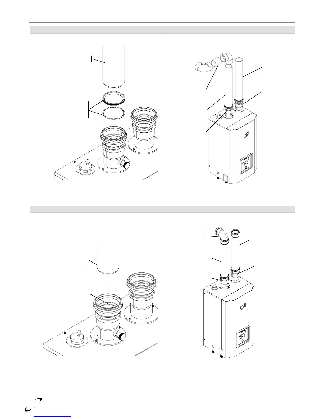
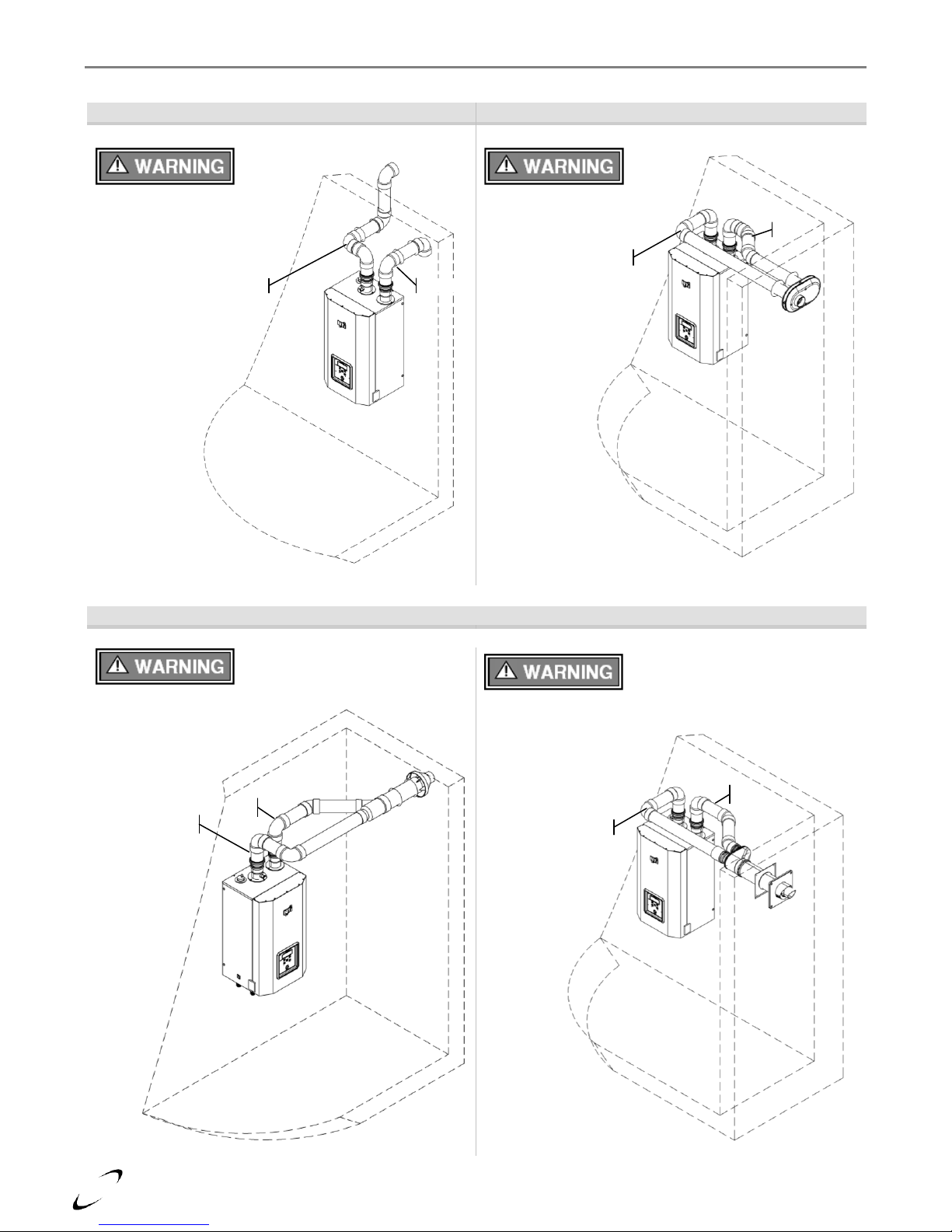
Near Boiler Vent/Air-inlet Piping
The Trinity Tx employs universal Vent and Air-inlet appliance adapters that accept either 3” PVC/CPVC or 3”
Polypropylene (PPs) venting, without the need for additional adapters. The appliance adapters incorporate two
seals, one for the larger diameter PVC/CPVC pipe (3.5” OD), and one for the smaller diameter PPs pipe (3.15”
OD). The exhaust/vent adapter uses a toothed-ring to prevent the vent pipe from being pulled out once it is
inserted.
PVC/CPVC Piping – Remove the lower gasket and toothed-ring from the exhaust adapter to avoid damage from
flue gas condensate; the 3” PVC/CPVC has an outside diameter of 3.5” and will seat into the upper portion of the
adapter. Ensure the upper gasket and toothed-ring are in place and properly positioned prior to installation.
Ensure the venting system does not apply a load or strain on the boiler flue outlet adapter; recommend using two
elbows to create a “swing joint” to reduce potential strain on vent piping and cemented joints. See Figure 4-2(a).
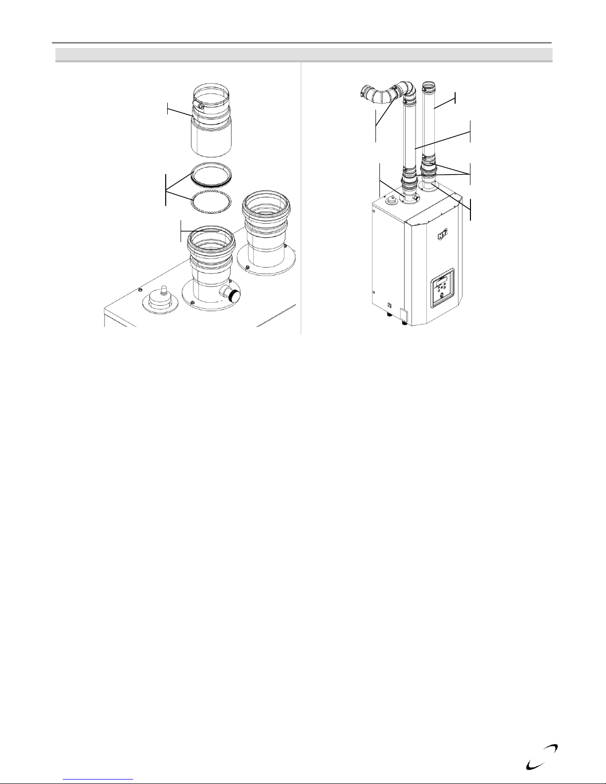
PPs Piping – 3” PPs has an outside diameter of 3.15” and will seat into the lower portion of the adapter. Ensure
the lower gasket and toothed-ring are in place and properly positioned prior to installation Ensure the venting
system does not apply a load or strain on the boiler flue outlet adapter; recommend using an elbow with an offset
to reduce potential strain on vent piping and cemented joints. See Figure 4-2(b).
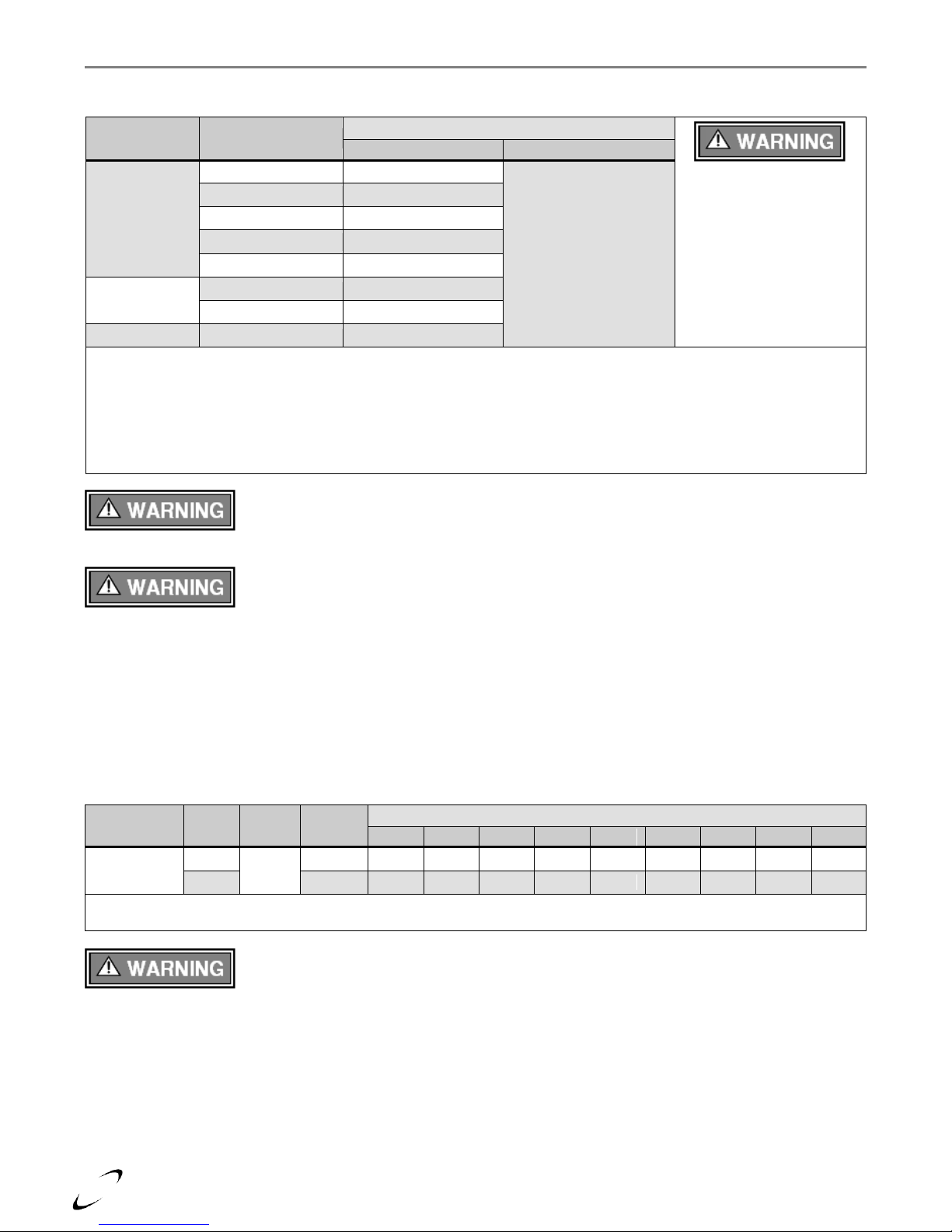
Stainless Steel Piping – The Trinity Tx has been tested and approved for use with DuraVent – FasNSeal AL29-
4C Stainless Steel Special Gas Vent. Venting with FasNSeal will require DuraVent adapter part number 300715
(contact DuraVent at 1-800-835-4429 or www.duravent.com). Remove the lower gasket and toothed-ring from
the appliance exhaust adapter to avoid damage from flue gas condensate; the DuraVent adapter has an outside
diameter of 3.5” and will seat into the upper portion of the appliance adapter. Ensure the upper gasket and
toothed-ring are in place and properly positioned prior to installation. Ensure the venting system does not apply
a load or strain on the boiler flue outlet adapter; recommend using two elbows to create a “swing joint” to reduce
potential strain on vent piping and cemented joints. See Figure 4-2(c).
Gasket Seating - Improper seating can cause leakage and eventual failure of the sealing
gasket. Ensure the vent pipe is properly beveled (approximately 1/8”) prior to inserting
into the boiler flue adapter. Failure to follow these instructions may result in serious injury or death.
Toothed-Ring - Failure to ensure the toothed-ring is properly in place and securing the
exhaust vent pipe to the appliance adapter may result in serious injury or death.
Exhaust venting must be supported to reduce strain on piping joints. Failure to follow
these instructions may result in result in damage, serious injury or death.
In Canada, the first 3 ft (915 mm) of vent piping must be readily accessible for inspection.
14
Figure 4-2(a) Near Boiler Vent Connections (PVC/CPVC)
Exhaust Vent Preparation (PVC/CPVC)
Near Boiler Venting (PVC/CPVC)
Figure 4-2(b) Near Boiler Vent Connections (PPs – Polypropylene)
Exhaust Vent Preparation (PPs)
Near Boiler Venting (PPs)
Air-inlet - check with applicable local codes for acceptable pipe material.
Flue Outlet
Adapter (factory
supplied)
PVC/CPVC
Exhaust Vent
Swing Joint
to attain slope in
horizontal runs
Air-inlet
Pipe *
Air Inlet
Adapter
(factory
supplied)
PVC/CPVC – w. 1/8” bevel
PPs Gasket & Ring –
remove lower gasket &
ring (not used w/PVC)
PVC Gasket & Ring – retain
upper gasket & ring
PPs Pipe – w. 1/8”
bevel
PPs Gasket & Ring –
retain lower gasket & ring
Air-inlet Adapter
(factory supplied)
PPs Elbow
w. offset angle to
account for slope
PPs Exhaust Vent
PPs Air-inlet Pipe*
Flue Outlet Adapter
(factory supplied)
Trinity Tx │Installation and Operation Instructions Tx Series
15
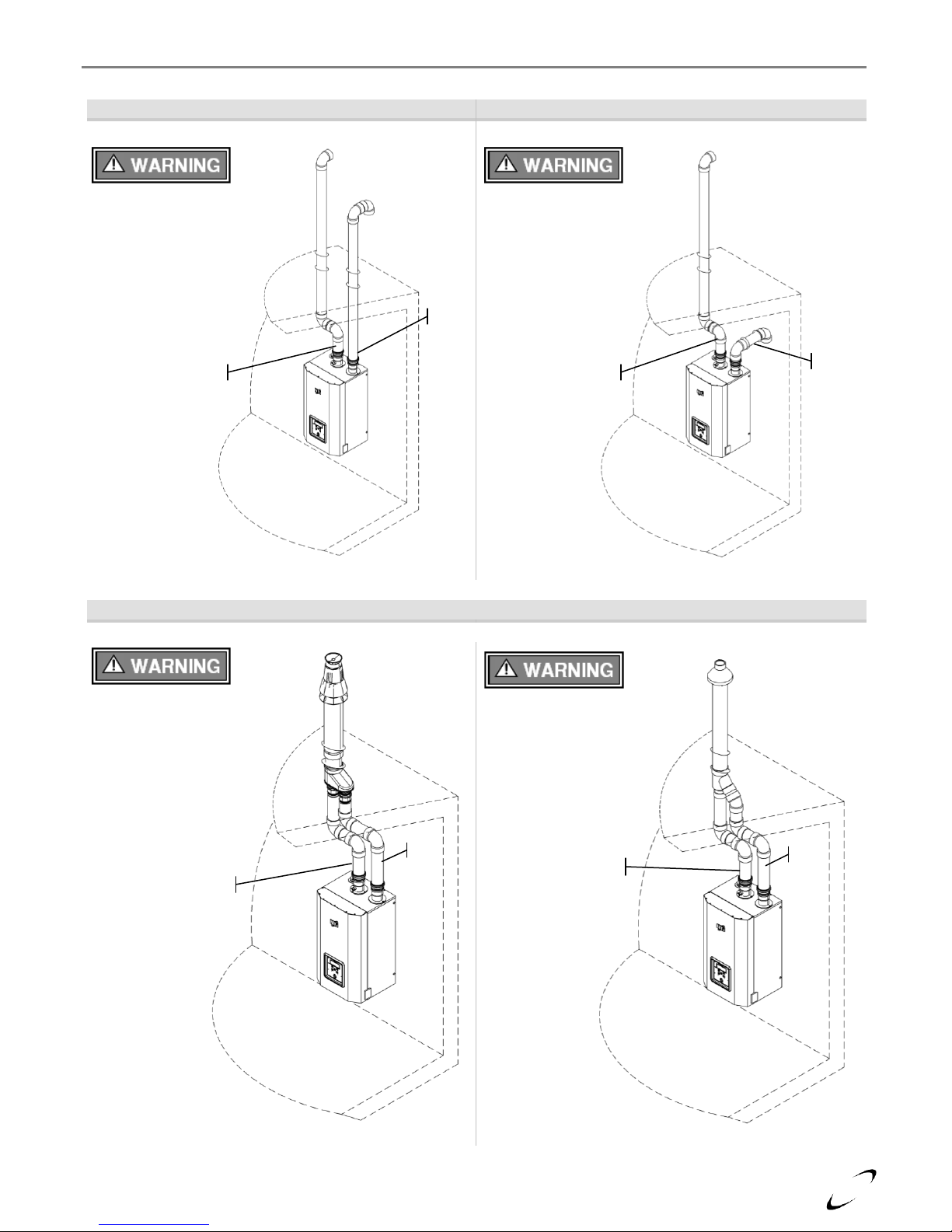
Figure 4-2(c) Near Boiler Vent Connections (SS – Stainless Steel)
Exhaust Vent Preparation (SS)
Near Boiler Venting (SS)
Flue Outlet
Adapter (factory
supplied)
SS Exhaust
Vent Pipe
Swing Joint
to attain slope in
horizontal runs
SS Air-inlet Pipe
SS Adapter
(Table 4-3)
Air-inlet Adapter
(factory supplied)
SS Adapter (Table 4-3)
PPs Gasket & Ring –
remove lower gasket &
ring (not used w/ PVC)
PVC Gasket & Ring – retain
upper gasket & ring
Tx Series Installation and Operation Instructions │Trinity Tx
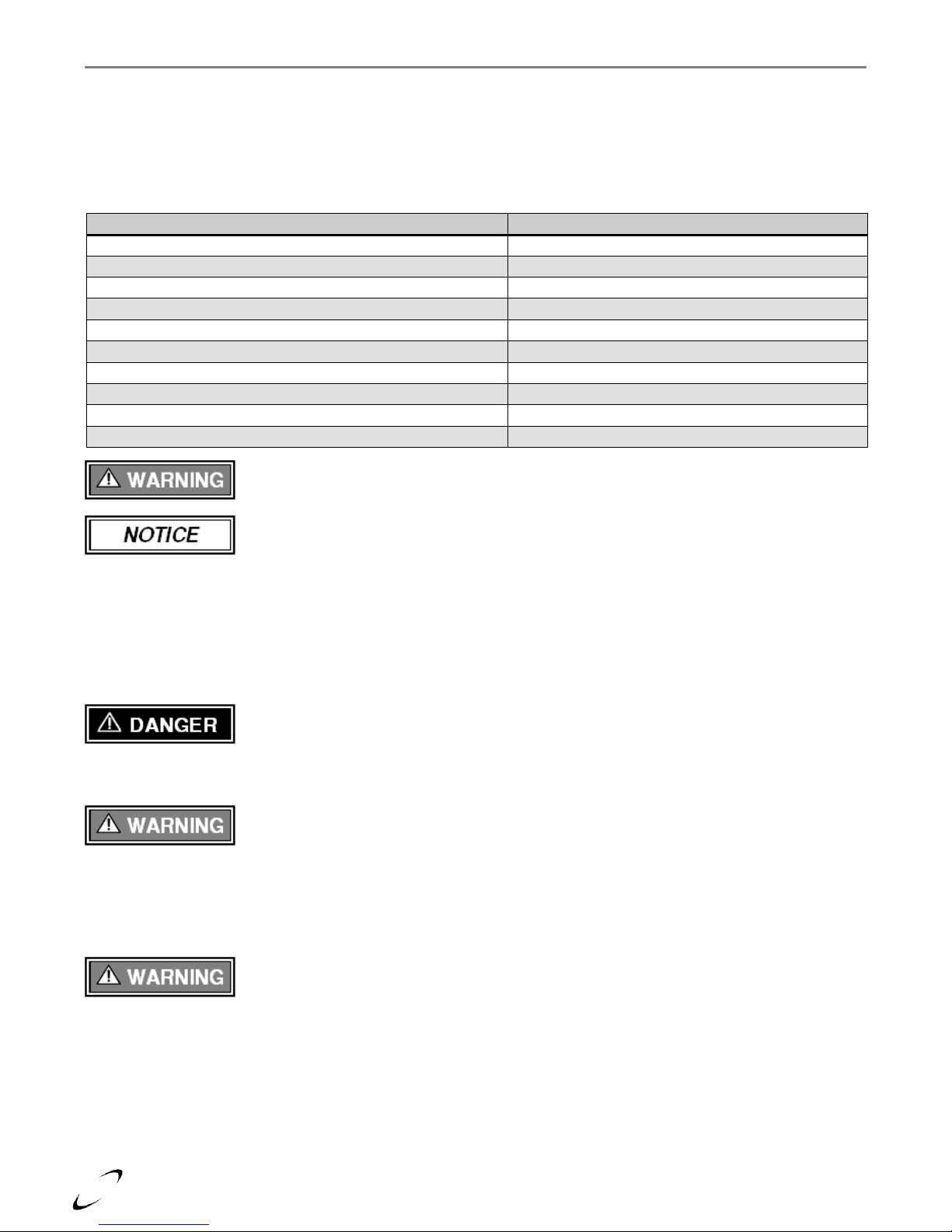
16
Items 1
Materials
2, 3
Venting System Standards
All Vent and Air-Inlet
materials installed on gas
fired appliances in CAN/US
must meet the Standards
listed in this Table. Failure
to comply could result in
fire, serious injury or death.
United States
Canada 4
Vent Piping
and Fittings
PVC - DWV
ANSI/ASTM D2265
All venting material in
Canada must be
ULC S636 approved.
See Note 4 below for
appropriate temperature
applications.
PVC Schedule 40
ANSI/ASTM D1785
CPVC Schedule 40
ANSI/ASTM F441
Stainless Steel (SS)
UL-1738
Polypropylene (PP)
-
Pipe Cement
PVC
ANSI/ASTM D2564
CPVC
ANSI/ASTM F493
Primers
PVC / CPVC
ANSI/ASTM F656
Notes:
1
Refer to Table 4-5 for Allowable Vent and Air-inlet Pipe Sizes and Lengths.
2
PVC venting (exhaust and air-inlet) is not permitted within the Closet/alcove of a Closet/alcove installation.
3
The Air-inlet does not require high temperature pipe material. Check applicable local codes for acceptable materials.
4
ULC S636 PVC is approved for flue gas temperatures up to 149oF (65oC) and must only be used for low temperature
applications. High temperature applications requiring boiler supply water temperatures greater than 140oF (60oC) must
use ULC S636 CPVC, PP or SS.
Model No.
Pipe
Size
Gas
Length
(ft)
Number of Elbows (90’s or 45’s) and Equivalent Feet
1 2 3 4 5 6 7 8 9
All Models
2”
1
NG/LP
100
95
90
85
80
75
70
65
60
55
3”
150
145
140
135
130
125
120
115
110
105
Note:
1
See WARNING below.
Trinity Tx │Installation and Operation Instructions Tx Series
Vent/Air-inlet Pipe Material
Table 4-2 Acceptable Vent and Air-inlet Pipe Material
The use of cellular core PVC (ASTM F891), cellular core CPVC, or Radel®
(polyphenolsulfone) in the exhaust venting system is prohibited. Failure to follow these
instructions may result in property damage, personal injury or death.
Covering non-metallic vent pipe and fittings with thermal insulation is prohibited. Failure
to follow these instructions may result in property damage, personal injury or death.
Vent/Air-inlet Pipe Length Determination
Use Table 4-5 to determine the maximum pipe length that can be used. The table calculates 90º elbows, and 45º
elbows at 5 equivalent feet each.
Example: When using 3” pipe, any Tx boiler can be installed with 150 equivalent feet of air-inlet piping and 150
equivalent feet of exhaust-vent piping. See Table 4-5 for more details.
Table 4-3 Allowable Vent and Air-inlet Pipe Size and Lengths
PVC Exhaust Venting – When using 2” PVC venting, the first seven (7) equivalent feet
of exhaust venting must be approved 2” CPVC or 3” PVC; see exceptions in Table 4-2.
17
Description
Vent
Size
Supplier P/N
Figure
Vent Material
Compatibility
Vent Option
Roof
Wall
IPEX Low Profile
(Flush Mount)
7
2”
196984
4-3(b), 4-5(c)
PVC/CPVC
7
3”
196985 (NTI P/N 84357)
IPEX Concentric
(Wall/Roof)
5,6,7
2”
196005
4-3(c), 4-4(c),
4-5(b), 4-6(b)
3”
196116 (NTI P/N 82666)
197009
DuraVent - PolyPro
Concentric (Wall)
2”
2PPS-HK
4-3(c), 4-5(d)
PVC/CPVC/PPs
3”
3PPS-HK
DuraVent - PolyPro
Concentric (Roof)
2”
2PPS-VK
4-4(c), 4-6(c)
3”
3PPS-VK
Centrotherm – InnoFlue
(Flush Mount)
2”
ISLPT0202
4-3(b), 4-5(c)
3”
ISLPT0303
Centrotherm – InnoFlue
Concentric (Wall)
8
2”
ICWS2413 & ICTC0224
4-3(c), 4-5(d)
3”
ICWS3513 & ICTC0335
ICWT352 & ICTC0335
Centrotherm – InnoFlue
Concentric (Roof)
8
2”
ICRT2439 & ICTC0224
4-4(c), 4-6(c)
3”
ICRT3539 & ICTC0335
Notes:
1
Instructions included with termination kits contain detailed assembly and installation instructions.
2
All factory termination kits are ULC S636 approved.
3
Clearance requirements in this manual supersede those of the instructions included with the vent terminal.
4
Piping MUST be secured to the vent terminal during installation.
5
IPEX Concentric Terminal MUST be cemented together and to the vent pipes during installation.
6
Vent Screens provided with boiler may be used with the IPEX Concentric Vent Kits; otherwise use IPEX vent screens
(2” vent screen P/N 196050; 3" vent screen P/N 196051 – each sold separately).
7
IPEX Low Profile and Concentric kits (excluding p/n 197009) are constructed out of ULC S636 approved PVC; check
with your local authority for the acceptance of PVC as a venting material prior to use.
8
Centrotherm Concentric termination kits must use the applicable “Twin pipe to concentric adapter”, part number
ICTC0224 or ICTC0336.
Tx Series Installation and Operation Instructions │Trinity Tx
Termination Options – Direct Vent Installation
The venting system of the Tx may be terminated using field supplied piping to construct a “Two-Pipe”
termination, see Figures 4-3a, 4-4a, 4-4d, 4-5a, 4-6a and 4-6d; alternatively the venting may be terminated using
a factory kit selected from Table 4-4.
Optional Termination Kits – Direct Vent Installation
Kits certified with the Trinity Tx are listed in Table 4-6 and available from IPEX, DuraVent, Centrotherm and/or
NTI. For more information on System 636 Vent Kits or wholesaler locations contact IPEX directly USA: 1-800463-9572 or www.IPEXamerica.com │ CAN: 1-866-473-9462 or www.ipexinc.com. For more information on
PolyPro Vent Kits or wholesaler locations contact DuraVent directly 1-800-835-4429 or www.duravent.com. For
more information on InnoFlue Vent Kits or wholesaler locations contact Centrotherm directly at 1-877-434-3432
or www.centrotherm.us.com.
Table 4-4 Optional Vent Termination Kits
Venting Options - Due to potential moisture loading (build-up) along the exterior wall,
sidewall venting may not be the preferred venting option (see Figures 4-4 and 4-6).
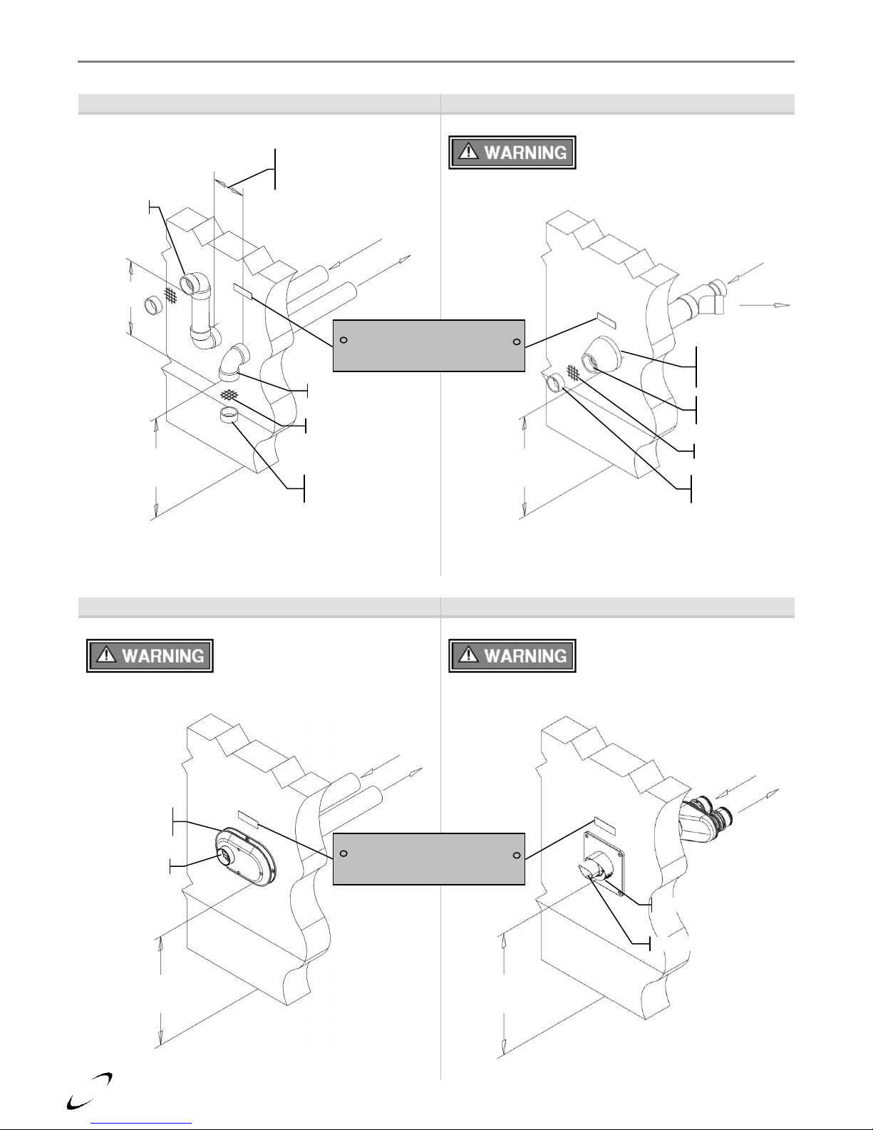
18
Figure 4-3(a)
Figure 4-3(b)
Two-pipe Termination (Sidewall)
Low Profile Termination (Sidewall)
Figure 4-3(c)
Concentric Termination (Sidewall)
Exhaust must terminate a
minimum of 18” above Air-inlet
termination; see Figure 4-5(a) for
more details.
Exhaust
Inlet
3” IPEX Low Profile Termination
illustrated; see Figure 4-5(c) for
more details.
Exhaust
Inlet
3” DuraVent Concentric
Termination illustrated, see
Figure 4-5(d) for more details.
Exhaust
Inlet
3” IPEX Concentric Termination
illustrated, see Figure 4-5(b) for
more details.
Exhaust
Inlet
Trinity Tx │Installation and Operation Instructions Tx Series
19
Figure 4-4(a)
Figure 4-4(b)
Two-pipe Termination (Roof)
Two-pipe Termination (Roof-exhaust / Sidewall-inlet)
Figure 4-4(c)
Concentric Termination (Roof)
3” DuraVent Concentric
Termination illustrated, see
Figure 4-6(c) for more details.
Exhaust
Inlet
Exhaust
Inlet
Exhaust must terminate a
minimum of 18” above the Airinlet termination; see Figure 46(a) for more details
3” IPEX Concentric termination
illustrated, see Figure 4-6(b) for
more details.
Exhaust
Inlet
Exhaust
Inlet
Exhaust must terminate a
minimum of 12” above snow
level; see Figure 4-6(d) for more
details
Tx Series Installation and Operation Instructions │Trinity Tx
20
Sidewall Termination Details – Direct Vent Installation
Figure 4-5(a)
Figure 4-5(b)
Two-Pipe Termination (Sidewall)
IPEX Concentric Termination (Sidewall)
Figure 4-5(c)
Figure 4-5(d)
Low Profile Termination (IPEX Illustrated)
PolyPro / InnoFlue Wall Termination
Exhaust
Air-inlet
Min. 12”
above grade
or snow level
Vertical
Min. 18”
Horizontal
4-12” or greater
than 36”
Exhaust
Air-inlet
Vent Screen
Vent pipe piece to
retain vent screen
Gas Vent Directly Below
Keep Free of Obstructions
Exhaust
Air-inlet
Min. 12”
above grade
or snow level
Air-inlet around
perimeter (1-2”
from wall)
Exhaust through
center
Vent Screen
Vent pipe piece to
retain vent screen
Refer to documentation included with termination kit for
complete installation instructions.
Refer to documentation included with termination kit for
complete installation instructions.
Refer to documentation included with termination kit for
complete installation instructions.
Min. 12”
above grade
or snow level
Exhaust
Air-inlet
Exhaust
Air-inlet around
perimeter
Min. 12”
above grade
or snow level
Exhaust center
Air-inlet bottom
Exhaust
Air-inlet
Gas Vent Directly Below
Keep Free of Obstructions
Trinity Tx │Installation and Operation Instructions Tx Series
Tx Series Installation and Operation Instructions │Trinity Tx
21
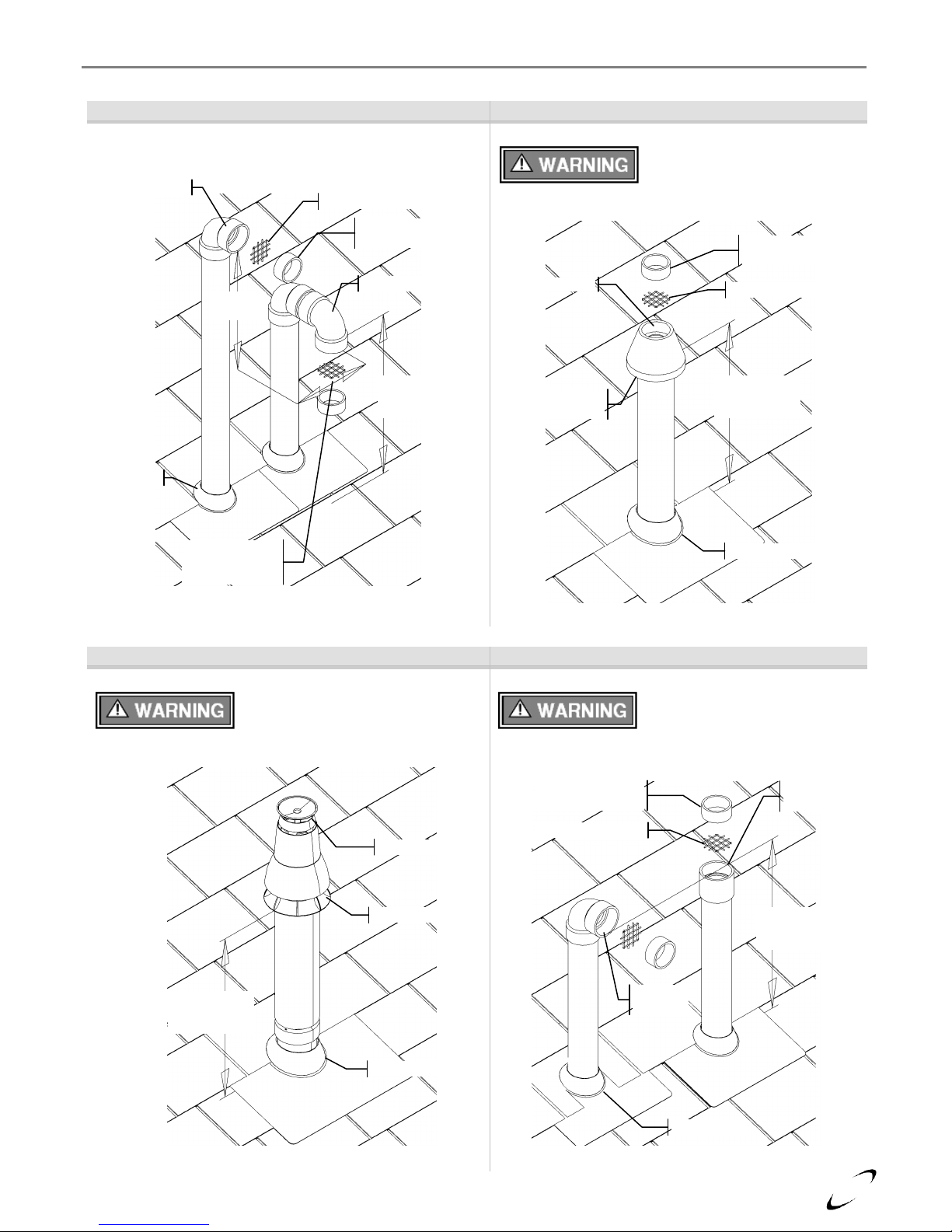
Roof Termination Details – Direct Vent Installation
Figure 4-6(a)
Figure 4-6(b)
Two-Pipe Termination (Roof)
IPEX Concentric Termination (Roof)
Figure 4-6(c)
Figure 4-6(d)
PolyPro / InnoFlue Roof Termination
Exhaust only Roof Termination
Min. 12”
above grade
or snow level
Vent Screen
Vent pipe piece to
retain vent screen
Exhaust
Air-inlet
Vertical
Min. 18”
Horizontal
4-12” or greater
than 36”
Flashing
Min. 12”
above grade
or snow level
Vent Screen
Vent pipe piece to
retain vent screen
Exhaust center
Air-inlet around
perimeter
Flashing
Refer to documentation included with termination kit for
complete installation instructions.
Refer to documentation included with termination kit for
complete installation instructions.
Min. 12”
above grade
or snow level
Flashing
Exhaust
Air-inlet
Figure illustrates two options for exhaust termination only;
neither vent pipe illustrated is for combustion air-inlet.
Min. 12”
above grade
or snow level
Flashing
Vent pipe piece to
retain vent screen
Vent Screen
Exhaust
Option 1
Exhaust
Option 2

22
Trinity Tx │Installation and Operation Instructions Tx Series
Venting Rules and Guidelines
1. Prevailing Winds: Ensure the vent is located where it will not be exposed to normal prevailing winds.
2. Combustion Air-inlet Contamination: Air for combustion must be drawn from an area free of dust and
contaminants. Combustion air containing chemicals such as chloride, fluoride, bromine or iodine or dust
and debris will cause corrosion damage of the heat exchanger voiding your NTI warranty. Refer to Table 41 for a list of corrosive products and contaminants sources to avoid.
3. Vertical Separation: The exhaust must be a minimum of 18” [457 mm] above the air inlet, and the air inlet
must always be a minimum of 12” [305 mm] plus snow allowance above any surface that will support snow.
(Two feet plus snow allowance is highly recommended). Consult your weather office for the maximum
typical snowfall for your region.
Example: New Brunswick Canada - typical maximum snowfall is 19”, thus the inlet must be (12”+19”) =
31” above grade and exhaust must be (31”+18”) = 49” above grade.
4. Horizontal Separation: The horizontal distance between the inlet and exhaust must be a minimum of 4”
[102 mm] center to center.
5. Wall Flashing: Under normal operating conditions this boiler will produce a plume of white gases, and
should be taken into consideration when selecting an adequate location. A 36” [915 mm] diameter stainless,
plastic, or vinyl shield can be used to flash the exterior of the residence.
6. Flue Gas Hazard: Position the vent termination where vapors cannot make accidental contact with people
and pets or damage nearby shrubs and plants.
7. Elbow Extensions: Elbows on outside of wall must be no more than ½” [13 mm] away from the wall.
8. Vent Sloping: All indoor exhaust piping must be on a slope back to the boiler a minimum of ¼” per linear
foot of vent [6.25 mm per linear 305 mm]. For applications where excessive condensation is possible ½” per
linear foot [13 mm per linear 305 mm] is recommended.
9. Vent Supports: Where required Vent and Air-inlet piping shall be secured to the wall for more rigidity. All
interior vent pipe shall be supported a minimum of every 36” [915 mm].
10. Roof Exhaust: In all roof applications the discharge must point away from the pitch of the roof.
11. Roof Flashing: Install adequate flashing where the pipe enters the roof, to prevent water leakage.
12. Rain Cap: Install and seal a rain cap over existing chimney openings, in vacant chimney applications.
13. Venting Below Grade: For installations that exit the wall below grade refer to Figure 4-7.
14. Vent Screens: Install factory supplied vent screens on the outside of the last elbow for both the inlet and
exhaust vent terminal elbows. Install the screen into the female opening of the elbow, and then cut a small
piece of pipe to sandwich the screen into the elbow. NOTE: ensure the small piece of pipe cut, does not
extend past the end of the elbow. Two screens are provided in the package. See Figures 4-5 and 4-6.
15. Condensate Hazard: Do not locate vent over public walkways, driveways or parking lots. Condensate
could drip and freeze resulting in a slip hazard or damage to vehicles and machinery.
16. Warning Plate: For Sidewall Venting, install the warning plate “Gas Vent Directly Below”, directly above
(within 4 ft [1.22 m] vertically) the location of the air-inlet pipe, so it is visible from at least 8 ft [2.4 m]
away. See Figure 4-5.
17. Wall Thickness: Direct vent terminations are designed to work with any standard wall thickness.
Installation guidelines for min/max wall thickness are as follows: Min.= 1” [25mm], Max.= 60” [1.52 m].
18. Venting Options: Due to potential moisture loading (build-up) along the exterior wall, sidewall venting
may not be the preferred venting option. Refer to Figures 4-4 and 4-6 for roof top venting options.
23
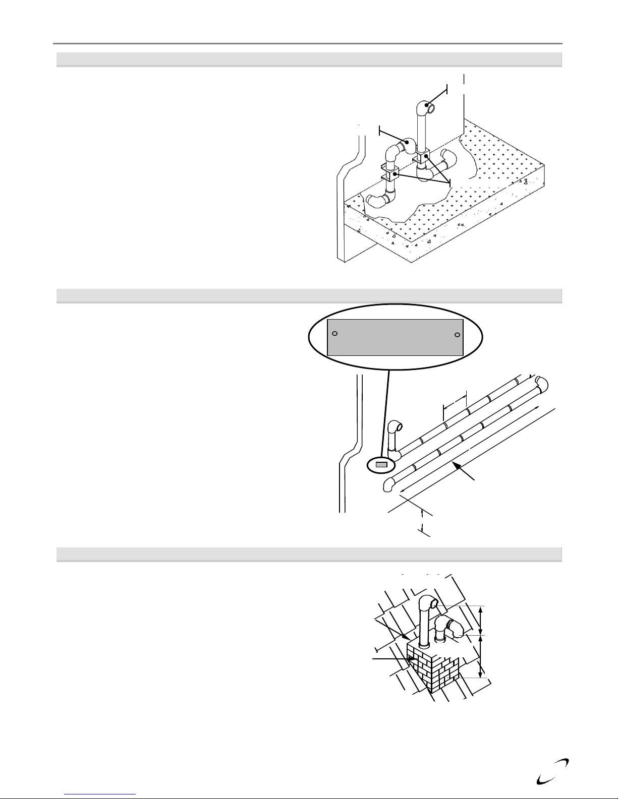
Figure 4-7 Venting Below Grade
For installations that exit the wall below grade:
1. Excavate site to a point below where the pipes
are to exit as shown.
2. Ensure the wall is fully sealed where the pipes
penetrate.
3. The Vent/Air-inlet piping MUST be secured to
the side of the building above grade, as shown,
to provide rigidity.
4. Optional mounting bracket PN. 82075 for
securing the exhaust pipes (only applicable for
3” PVC/CPVC venting).
5. Ensure that the Vent/Air-inlet clearances are
maintained, see Section 5.0 for details.
Figure 4-8 Outdoor Horizontal Venting
Vent piping outside the Building is permitted under
the following conditions:
1. The maximum length outside the building is 20
feet [6.1 m]. Note that outdoor length must be
included in the overall vent length calculation.
2. All normal termination clearances are maintained.
3. The pipe is supported every 24” [610 mm].
4. The exhaust and inlet are sloped back to the boiler
½” elevation for every linear foot [13 mm for
every linear 305 mm].
Figure 4-9 Existing Chimney Chase Way
It is permissible to use an existing chimney as a chase
way to run the Vent/Air-inlet piping as long as:
1. The chimney is not being used by any other
boiler.
2. Flue gases don’t enter the vacant chimney.
3. Only Trinity certified venting materials are used,
see Section 4.0.
4. Vent lengths are within the maximums specified.
5. The top of the chimney is capped and the
Vent/Air-inlet pipes are flashed to prevent
leakage into the vacant chimney.
Air-Inlet
Existing
Chimney
(used as a
chase way)
Chimney
Cap
Exhaust Vent
Exhaust Vent Min.
18” [457 mm]
above air-inlet
Air-Inlet
Min. 12” [305 mm]
above roof and
snow level
Supports every
24” [610 mm]
12” [305 mm] plus snow
allowance above grade
Air-Inlet
Maximum of 20 ft
[6.1 m] is permitted
for piping outside a
building.
Exhaust
Vent
Gas Vent Directly Below
Keep Free of Obstructions
Exhaust
Air-inlet
Wall Brackets
Tx Series Installation and Operation Instructions │Trinity Tx
24
Clearances to Air-Inlet Termination
Canada 1
USA 2
Min. Distance
Min. Distance
A
Above grade/roofline and snow level 8
12 in.
305 mm
12 in.
305 mm
B
Above roof line - Concentric Vent
6, 11, 13
24 in.
610 mm
24 in.
610 mm
C
To exhaust vent from any other boiler
36 in.
915 mm
12 in.
305 mm
Clearances to Exhaust Vent Termination
Min. Distance
Min. Distance
D
Minimum vertical separation above air inlet 9
18 in.
457 mm
18 in.
457 mm
E
Minimum horizontal separation from air inlet 3
4 in.
102 mm
4 in.
102 mm
F
Window, door or building opening
36 in.
915 mm
12 in.
305 mm
G
To combustion air inlet from any other boiler
36 in.
915 mm
12 in.
305 mm
H
Non-mechanical air supply inlet to building
36 in.
915 mm
12 in.
305 mm
I
Mechanical air supply inlet to building 4
6 ft.
1.83 m
3 ft.
915 mm
J
Soffit, overhang, eave or parapet
24 in.
610 mm
24 in.
610 mm
K
Soffit vent or vent opening in an overhang, eave or parapet
6 ft.
1.83 m
6 ft.
1.83 m
L
Outside corner 10
- - -
-
M
Inside corner of an L-shaped structure (including walls and fences)
36 in.
915 mm
36 in.
915 mm
N
Electric meters, gas meters, regulators and relief equipment
6 ft.
1.83 m
4 ft.
1.22 m
P
Each side of center line above or below meters, regulators and relief devices 5
36 in.
915 mm
36 in.
915 mm
Q
Above a paved sidewalk, driveway, or parking lot on public property if adjacent 12
7 ft.
2.13 m
7 ft.
2.13 m
R
Above a sidewalk, driveway, or parking lot on public property
X X X
X
S
Above a sidewalk, driveway on private property between / serving both dwellings
X X X
X
T
Under a concrete veranda, porch, deck, or balcony 7
24 in.
610 mm
24 in.
610 mm
U
Above, under or near exterior stairs
X X X
X
V
Into a canopy or carport
X X X
X
Notes:
1 - Canadian installations must comply with the current CSA B149.1 Natural Gas and Propane Installation Code and local
building codes.
2 - US installations must comply with current ANSI Z223.1/ NFPA 54 National Fuel Gas Code and local building codes.
3 - Horizontal separation center-to-center (c.c.) 4”-12” (102-305 mm).
4 - For US installations, an exhaust vent may be 3 ft above a mechanical air supply inlet if within 10 ft. [3 m] horizontally.
5 - Horizontal clearance must be observed up to a height of 15 ft. [4.6 m] above/below the meter, regulator, or relief devices.
6 - Concentric Vent must protrude from the roof precisely 24” [610 mm] measuring from the terminal end-cap vanes.
7 - Permitted if veranda, porch, deck, or balcony is made of concrete and a minimum of two sides are fully open beneath.
8 - 24” is the recommended snow level allowance above grade/roofline or any surface that will support snow, debris, or ice
(i.e. for roof venting clearances - roofline and snow level). If living in a snowfall region, consult your local weather
office for the maximum typical snowfall for your area.
9 - Note that the vent must maintain a minimum vertical distance above the air-inlet. Example: Vent height = 18” (457
mm) above air inlet + 12” (305 mm) for air inlet above grade/roof line and snow level = 30” (762 mm) above grade and
snow level.
10 - Clearances to an outside corner to be in accordance with local installation codes.
11 - In Canada, concentric vent materials are subject to approval by local inspectors. See Termination Kits in Section 4.0.
12 - Above public walkways, driveways or parking lots if adjacent to it and condensate cannot drip, freeze, or create a hazard.
13 - Contact the manufacturer for special exemptions relating to multiple boiler installations using concentric vents.
Trinity Tx │Installation and Operation Instructions Tx Series
5.0 VENT/AIR-INLET TERMINATION CLEARANCES
instructions detailed in this section are a combination of Trinity Tx specific and National Gas Code restrictions.
Compliance alone doesn’t insure a satisfactory installation as good common sense must also be applied. Failure
to follow these instructions may result in fire, property damage, serious injury or death.
Table 5-1 Termination Clearances Quick Reference Table (See Figures 5-1 and 5-2)
The quick reference table below is to be read in conjunction with the numbered notes as
indicated, Figures 5-1 and 5-2, and the Venting Rules and Guidelines in Section 4.0. The
25
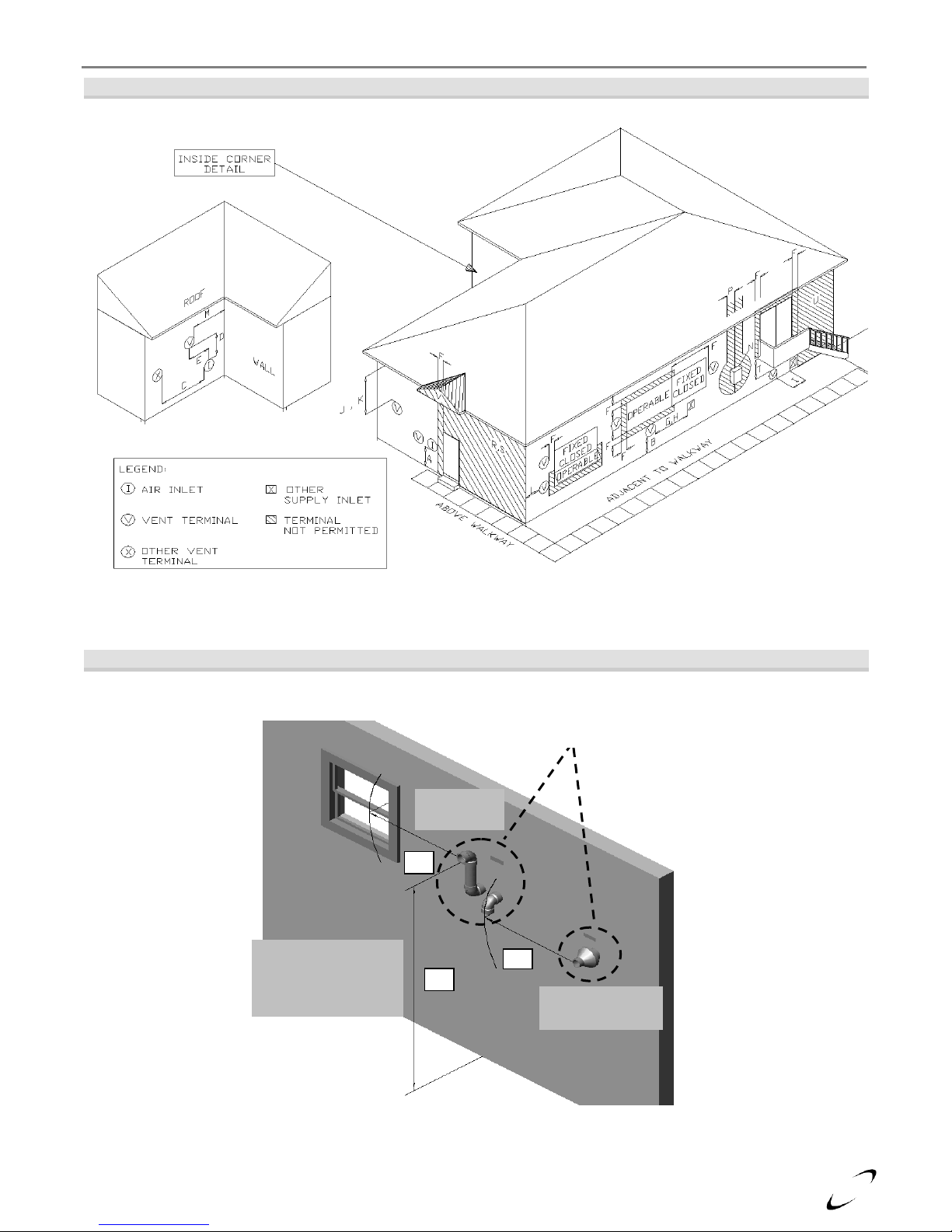
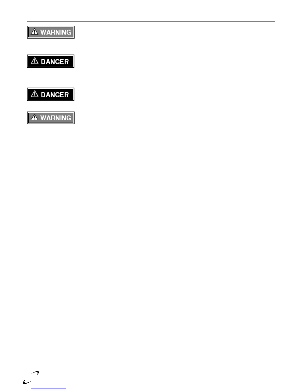
G – Letter represents a specific Termination Position. Refer to Table 5-1 for corresponding termination clearances.
Concentric Vent
Termination
Q
Two-Pipe
Termination
F
Clearance “Q”
Adjacent to Public
Walkway or Driveway
Minimum 7ft [2.13 m]
G
Clearances “F” and “G”
Canada – Minimum 3 ft [915 mm]
The US – Minimum 1 ft [305 mm]
Tx Series Installation and Operation Instructions │Trinity Tx
Figure 5-1 Termination Clearance Quick Reference Diagram (See Table 5-1)
Illustrations of Termination Clearances
Figure 5-2 Sidewall Termination (See Table 5-1)
26
Trinity Tx │Installation and Operation Instructions Tx Series
may result in venting or boiler component failure resulting in flue gas spillage leading to property damage,
serious injury or death.
result in fire, property damage, serious injury or death.
Removing an Existing Boiler from Common Venting System
emissions into the surrounding air resulting in serious injury or death.
connected to it. Instructions have been provided on how to remove the existing boiler and how to resize the
remaining venting system. Failure to follow these instructions may result in property damage, serious injury or
death.
Upon removal of an existing boiler, the following steps shall be followed for each boiler remaining in the
common venting system; prior to commencing this procedure, shutdown all boilers remaining in the common
venting system.
Steps to Removing an Existing Boiler:
1. Seal any unused openings in the common venting system.
2. Visually inspect the venting system for proper size and horizontal pitch. Verify that there is no blockage,
restriction, leakage, corrosion or other deficiencies which could cause an unsafe condition.
3. Insofar as is practical, close fireplace dampers, all building doors and windows and all doors between the
space in which the boilers remaining connected to the common venting system are located and other spaces
of the building. Turn on clothes dryers and any boiler not connected to the common venting system. Turn on
any exhaust fans, such as range hoods and bathroom exhausts, so they will operate at maximum speed. Do
not operate a summer exhaust fan.
4. Place in operation the boiler being inspected. Follow the applicable lighting instructions. Adjust thermostat
so boiler will operate continuously.
5. Test for spillage at the draft hood relief opening after 5 minutes of main burner operation. Use the flame of a
match or candle, or smoke from a cigarette, cigar or pipe.
6. After it has been determined that each boiler remaining connected to the common venting system properly
vents when tested as outlined above, return doors, windows, exhaust fans, fireplace dampers and any other
gas burning boiler to their previous condition of use.
7. Any improper operation of the common venting system should be corrected so the installation conforms to
the National Fuel Gas Code, ANSI Z223.1/NFPA 54 and/or CAN/CSA B149.1, Natural Gas and Propane
Installation Code. When resizing any portion of the common venting system, the common venting system
should be resized to approach the minimum size as determined using the appropriate tables in Part 11 of the
National Fuel Gas Code, ANSI Z223.1/NFPA 54 and/or CAN/CSA B149.1, Natural Gas and Propane
Installation Code.
Extra precaution must be taken to adequately support the weight of the Vent/Air-inlet
piping in applications using roof-top terminations. Failure to follow these instructions
Under no circumstances may an existing chimney or chase-way be used to vent or
provide combustion intake air to a Trinity Tx. Failure to follow these instructions will
Do not install the Trinity Tx into a common venting system with any other boiler. Failure
to comply with this warning will cause flue gas spillage and leech carbon monoxide
When an existing boiler is removed from a common venting system, the common
venting system is likely to be too large for proper venting of the remaining boilers
 Loading...