

Trinity TBFLWH-1404 Owner's Manual

OWNER’S MANUAL
TRINITY WOOD KITCHEN CART
w/DRAWERS AND TRAY - WHITE
Model # TBFLWH-1404
Everything in its place.
®
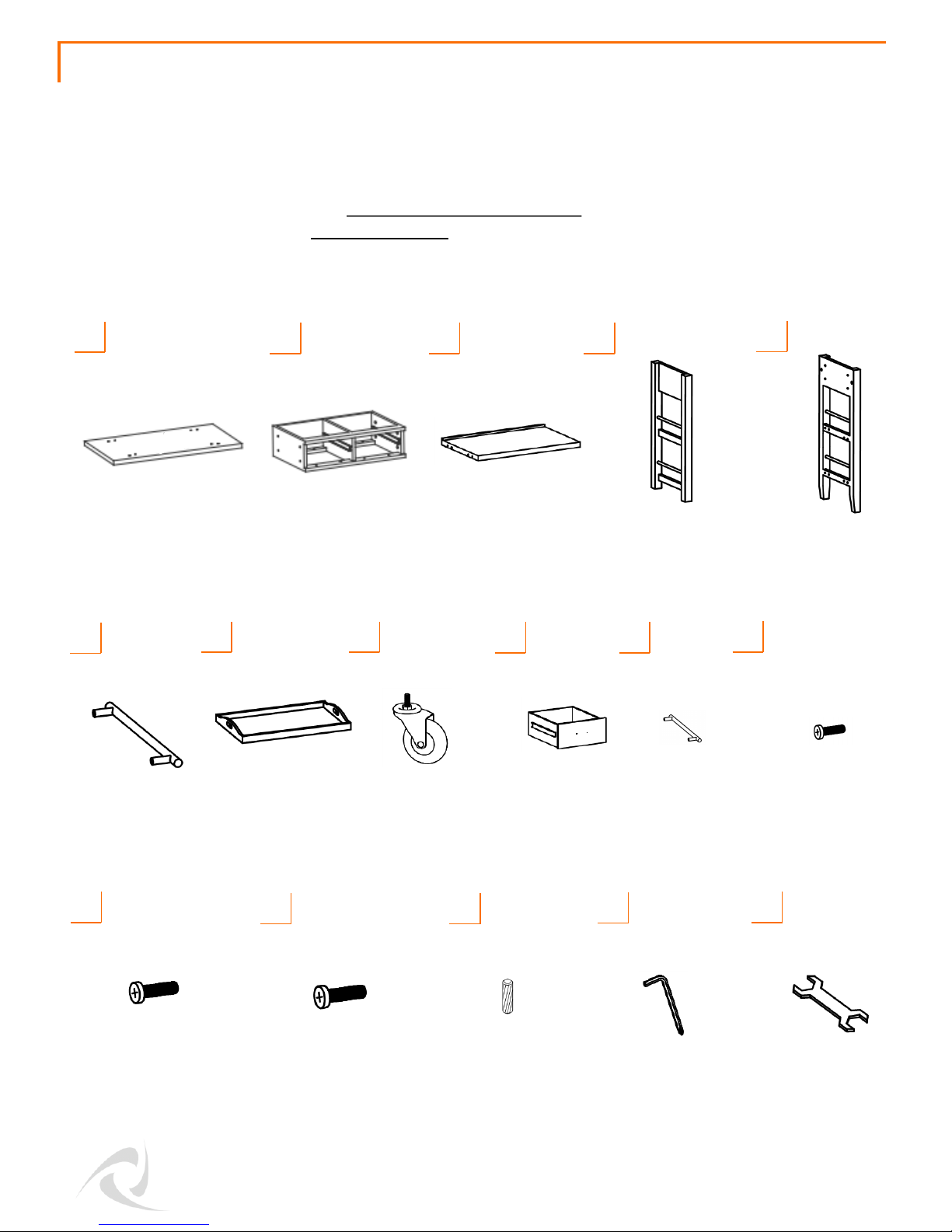
Your TRINITY Wood Kitchen Cart w/Drawers and Tray should include the following parts. Please inspect
box contents to ensure you have received all components.
If you are missing any parts, need assistance with assembly or have questions, please contact TRINITY
Customer Service: 800.985.5506 or customerservice@trinityii.com. Parts can also be requested online
via our “Contact Us” section at www.trinityii.com.
You may use a power screwdriver for easier assembly.
PARTS LIST
WOOD TOP (1)
A
SHELF (2)
C D
FRAME SCREW (20)
28mm Black
G
L
M
CASTER
SIDEFRAME (1)
TRAY (1)
H
DRAWER (2)
Packed in Wood Top
HANDLE SCREW (2)
43mm Silver
© 2017 TRINITY - 800.985.5506
1
E
HANDLE
SIDEFRAME (1)
CASTER (2)
I
N
DOWEL (12)
O
SCREWDRIVER (1)
P
WRENCH (1)
DRAWER
PULL (2)
J
PULL SCREW (4)
20mm Silver
K
SIDE
HANDLE (1)
F
DRAWER
FRAME (1)
B
ASSEMBLY INSTRUCTIONS
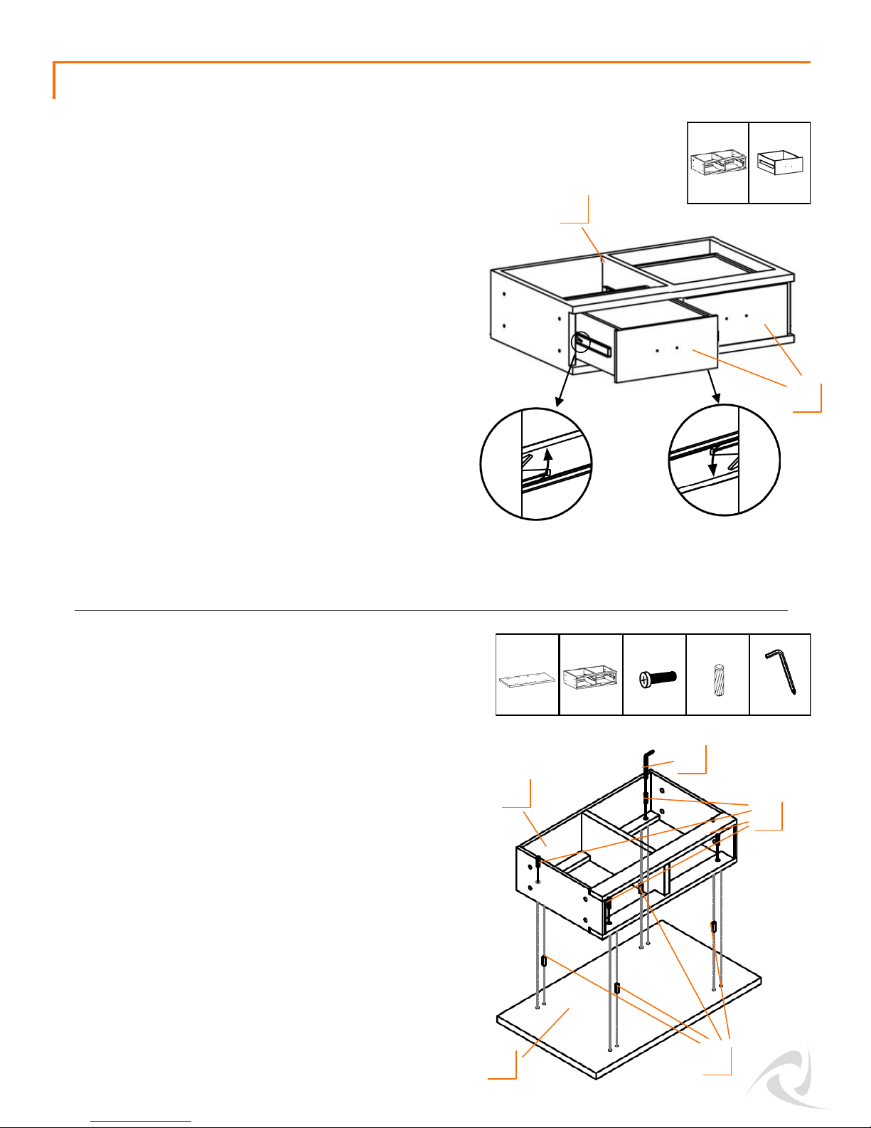
Locate DRAWER FRAME (B) from the box and notice
that both DRAWERS (I) are preinstalled.
You will need to remove both DRAWERS (I) before
starting assembly of the Kitchen Cart.
Push one DRAWER (I) out from inside the DRAWER
FRAME (B) so that it is almost fully extended. Keep the
other DRAWER (I) closed so you can reach release levers
on both sides. On the LEFT-hand side, pull the black
release lever UP. On the RIGHT-hand side, push the
black release lever DOWN. While holding the levers as
instructed, pull the DRAWER (I) forward until released
from the slides attached to the DRAWER FRAME (B).
Repeat for the other DRAWER (I) so that both
DRAWERS (I) are removed. Set both aside.
© 2017 TRINITY - 800.985.5506
2
STEP 1
B (1) I (2)
On a clean surface, lay the WOOD TOP (A) on its
top surface, the side without the holes.
Insert (4) DOWELS (N) into the (4) inside holes of
each corner of the WOOD TOP (A).
Carefully place DRAWER FRAME (B) over the
DOWELS (N), aligning the (4) holes closest to
each corner of the DRAWER FRAME (B) with the
(4) DOWELS (N). Then push down evenly until
DRAWER FRAME (B) is pressed against WOOD
TOP (A).
Insert FRAME SCREW (L) through DRAWER
FRAME (B) and fasten to WOOD TOP (A) using
SCREWDRIVER (O). Make sure all SCREWS (L) are
tightened.
Left-hand side
Right-hand side
STEP 2
A (1) B (1)
B
I
O (1)
N (4)
L (4)
A
N
B
L
O
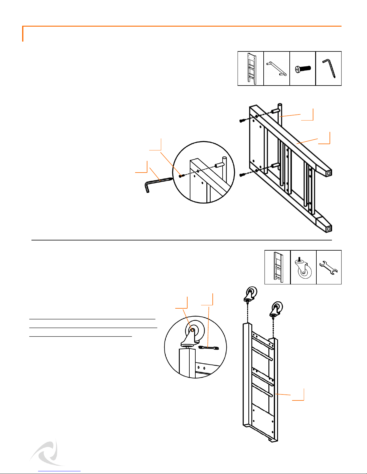
ASSEMBLY INSTRUCTIONS
Screw CASTERS (H) into nuts at the bottom of
CASTER SIDEFRAME (D). Tighten CASTERS (H)
with WRENCH (P).
Use the provided caster wrench to tighten
completely. Failure to do as instructed could
result in the caster stem breaking.
Place HANDLE SCREWS (M) through holes in
the HANDLE SIDEFRAME (E) and tighten with
SCREWDRIVER (O) to nuts in SIDE HANDLE (F).
Please note that the HANDLE SIDEFRAME (E) has FOOT
PADS on the bottom.
STEP 3
STEP 4
M (2) O (1)
E (1) F (1)
E
F
D
H (2) P (1)
D (1)
H
M
O
P
© 2017 TRINITY - 800.985.5506
3
 Loading...