

Trinity SRT Series, SRT-350, HBA Series Assembly Manual

ENERGY ABSORPTION SYSTEMS
SRT-350
Guardrail End
Treatment
Assembly Manual
Part No. 620295B Revised March 2010
®
6 POST

2
SRTTM/ HBA
TM
6-POST SYSTEM
FOR SPECIFIC DETAILS, REFER TO THE
STATE STANDARD DRAWING
"3-'6
"3-'6
"3-'6
"3-'6
"3-'6
"3-'6

SRT
TM
/ HBA
TM
6-POST SYSTEM
BILL OF MATERIAL ENGLISH (METRIC)
(FOR QUANTITIES, SEE STATES OPTION(S))
PC
3G 12/12"/ BACKUP (2.67/0.305) GUARDRAIL
9G 12/12.5'/6'3"/S (2.67/3.81/1.905/S) GUARDRAIL
30G 12/12.5'/6'3"/S (2.67/3.81/1.905/S) SRT-1 ANC GUARDRAIL
39G 12/12.5'/6'3"/S (2.67/3.81/1.905/S) SR T-2 GUARDRAIL
700A CABLE ANCHOR BRACKET
907G 12 (2.67)/BUFFER/ROLLED (TERMINAL)
3000G CABLE ASSEMBLY 3/4" x 6'6" (19 x 1981)
3300G 5/8" (16) WASHER
3340G 5/8" (16) HGR NUT
3360G 5/8" DIA. x 1 1/4" (16 DIA x 35) HGR SPLICE BOLT
3380G 5/8" DIA. x 1 1/2" (16 DIA. x 38) HEX HEAD BOLT
3400G 5/8" DIA x 2" (16 DIA. x 50) POST BOLT
3580G 5/8" DIA x 18" (16 DIA x 460) HGR POST BOLT
3701G 3/4" (19) WASHER
3704G 3/4" (19) HEX NUT
3718G 3/4" DIA X 3 "(19 DIA. x 75) HIGH STRENGTH HEX HEAD
3900G 1" (25) WASHER
3910G 1" (25) HEX NUT
4063B WOOD POST 6" x 8" x 6'0" (150 x 200 X 1830)
4075B WOOD BLOCK 6" x 8" x 14" (150 x 200 x 360) DR
4254G 3/8" (10) WASHER
4258G 3/8" (10) LOCKWASHER
4261G 3/8" x 1 1/2" (10 DIA. x 38) HEX HEAD BOLT (GR 5)
4699G 3/4" (19) LOCKWASHER
6321G 3/8" DIA. X 2 " (10 DIA x 50) HEX HEAD BOLT (GR 5)
6405G 3/8" (10) HEX NUT
9960G SLOT GUARD
9961G 3/8" x
33876A HBA POST 1 TOP (W6 x 8.5)
33877A HBA POST 2 TOP (W6 x 8.5)
33878A HBA POST 1 & 2 BOT (TS 6 x 4)
33879G ANGLE STRUT 2" X 2" X 3/8" (50 x 50 x 10)
33880G 1" x 6" x 8" (25 x 150 x 200) BEARING PLATE
33881G CABLE WEB PL 4" x 1/4" x 5 3/4" (100 x 6 x 146)
QTY DESCRIPTION
1
1
1
1
1
1
1
14
58
44
8
2
4
10
4
4
BOLT
1
1
4
4
5
4
1
4
4
5
4
1
1
1
2
2
1
1
3" x 4" (10 x 75 x 100) PLATE WASHER
DELINEATION OPTIONS
6665B 1 STRIPED (YELLOW/BLACK) REFLECTOR 16" x 16"
(400 x 400)
3

4
INSTALLING THE
SRT
TM
/ HBATM6-POST SYSTEM
MATERIALS
As packaged, the SRTTM/HBATMPost System includes all materials needed
for the installation.
Note that concrete footings or foundations are not required.
TOOLS REQUIRED
Tools required are those ordinarily used to install standard highway
guardrail (HGR). They include 9/16", 15/16", 1-1/4" and 1-1/2" sockets
and wrenches and such other equipment as augers and post pounders
commonly used in driving posts.
SITE PREPARATION
Site grading is usually necessary for the proper placement of the HBA
TM
posts and the Controlled Release Terminal (CRT) posts. It is suggested
that this grading be completed before the start of the installation of the
SRT
TM
/HBATM.
INSTALLATION
Be sure adequate time is allowed for "same day" complete installation.
If special field conditions are encountered when installing t he
SRT
TM
/HBATMPost System, contact Trinity Engineering @ 1-800-644-7976
to review the conditions.
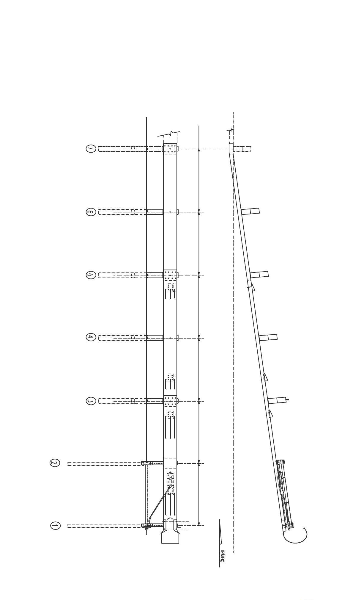
POST LAYOUT
The SRTTM/HBATMPost System is a 37'6" (11.43 m) that utilizes a straight
flare. Start at the end (post location 7) of the guardrail run and measure
along the flared system a distance of 37'6" (11.43 m). At this point,
measure an offset of 4'0" (1.21 m) perpendicular to the road. This
establishes the face location of post no. 1. A straight line between post
no. 1 and face of the blockout of post no. 7 establishes the location of
either the face of the post or the face of the blockout for each of the
posts. All posts are spaced at 6'3" (1905 mm) on center.
Trinity Highway Products drawings for the SRT should be used with
these instructions. The states standard drawings for this system need
to be reviewed for details that will be specific to that state.
The SRT™/HBA™ Post System has a straight flare; the earlier versions of
the SRT-350™ used a parabolic (curved) flare. At posts one and two,
HBA™ posts are used in place of the soil tubes and wood posts. The
same equipment and expertise is required for both systems. Anyone with
experience installing the SRT-350™ should have no difficulty installing the
SRT™/HBA™ Post System.
 Loading...