


BarrierGate
®
For Manual Operation
Product Description
Instructional Manual
Revision A May 2013Part No. 619183B

®
BarrierGate
For Manual Operation
Product Description
Instructional Manual
2525 Stemmons Freeway
Dallas, Texas 75207
Important:
assembly, maintenance, and repair of the BarrierGate
instructions are for standard assembly specified by the appropriate highway
authority only. In the event the specified system assembly, maintenance, or
repair would require a deviation from standard assembly parameters, contact the
appropriate highway authority engineer. This system has been accepted for use
by the Federal Highway Administration for use on the national highway system
under strict criteria utilized by that agency. Energy Absorption Systems
representatives are available for consultation if required.
This Manual must be available to the worker overseeing and/or assembling the product
at all times. For additional copies, contact Energy Absorption Systems at (888) 323-6374
or download from websites below.
The instructions contained in this Manual supersede all previous information and Manuals. All
information, illustrations, and specifications in this Manual are based on the latest BarrierGate
system information available to Energy Absorption Systems at the time of printing. We reserve
the right to make changes at any time. Please contact Energy Absorption Systems to confirm
that you are referring to the most current instructions.
These instructions are to be used only in conjunction with the
®
system. These
®
Part No. 619183B
www.energyabsorption.com Revision A May 2013
www.highwayguardrail.com 1 All rights in copyright reserved

Table of Contents
Customer Service Contacts .............................................................................................. 3
Important Introductory Notes ............................................................................................ 3
Recommended Safety Rules for Assembly ...................................................................... 4
Safety Symbols ................................................................................................................. 5
Warnings and Cautions ..................................................................................................... 5
Limitations and Warnings .................................................................................................. 6
Operation .......................................................................................................................... 7
Maintenance ..................................................................................................................... 8
Drive-By Inspection ........................................................................................................... 8
Walk-Up Inspection ........................................................................................................... 8
Troubleshooting and Repair ............................................................................................ 10
BarrierGate
BarrierGate
Concrete Pad, BarrierGate
Anchor Assembly, BarrierGate
Wall Assembly Pulley, BarrierGate
Wall Assembly Capstan, BarrierGate
Track Assembly, BarrierGate
Gate Assembly, Hook Section, BarrierGate
Gate Assembly, Pin Section, BarrierGate
Debris Skirt Assembly Pin or Hook Section, BarrierGate
®
Repair Guidelines ...................................................................................... 11
®
1.5 Manual Operation ................................................................................ 13
®
1.5 ...................................................................................... 16
®
1.5 ................................................................................ 17
®
1.5 ......................................................................... 19
®
®
1.5 .................................................................................. 23
1.5 ...................................................................... 21
®
1.5 ............................................................ 24
®
1.5 ............................................................... 26
®
1.5 ........................................ 28
www.energyabsorption.com Revision A May 2013
www.highwayguardrail.com 2 All rights in copyright reserved

Customer Service Contacts
Energy Absorption Systems (a Trinity Highway Products company) is committed to the highest
level of customer service. Feedback regarding the BarrierGate
®
system, its assembly
procedures, supporting documentation, and performance is always welcome. Additional
information can be obtained from the contact information below:
Energy Absorption Systems:
Telephone: (888) 323-6374 (USA Only)
(214) 589-8140 (USA or International)
E-mail: customerservice@energyabsorption.com
Internet: Energy Absorption Systems
Trinity Highway Products, LLC
http://www.energyabsorption.com
http://www.highwayguardrail.com
Important Introductory Notes
Proper assembly, deployment, and future maintenance of the BarrierGate® are critical to
achieve performance of the system under appropriate federal and state criteria. These
instructions should be read in their entirety and understood before assembly of the system.
Take the time to review this Manual thoroughly before performing all necessary work. Do not
attempt to assemble any BarrierGate
highway authority and instructional Manual from the manufacturer. If you need additional
information, or have questions about the BarrierGate
authority that has planned and specified this assembly and, if needed, contact Energy
Absorption Systems Customer Service Department. These instructions are to be used only in
conjunction with the assembly of the BarrierGate
as specified by the applicable highway authority. In the event your system assembly requires or
involves deviation from standard parameters, or during the assembly process a question arises
regarding a particular assembly step, please contact the appropriate highway authority that
specified this system at this location before proceeding. Energy Absorption Systems is available
for consultation with that agency. These instructions are intended for an individual who is
qualified to both read and accurately interpret them as written. They are intended for the
individual who is experienced and skilled in the assembly of highway products which are
specified and selected by the highway authority.
®
without the proper plans and specifications from the
®
system, please contact the highway
®
system and are for standard assemblies only
www.energyabsorption.com Revision A May 2013
www.highwayguardrail.com 3 All rights in copyright reserved
Important: Read safety instructions thoroughly and follow the assembly
directions and suggested safe practices before assembling, maintaining, or
repairing the BarrierGate
serious injury or death to the worker and/or bystanders. It further compromises
the acceptance of this system by the FHWA. Please have these instructions
available for reference by anyone involved in the assembly of the system.
Warning: Ensure that all of the BarrierGate
Important statements within the BarrierGate
Failure to follow this warning could result in serious injury or death in the event of
a collision.
®
system. Failure to follow this warning can result in
®
system Warnings, Cautions, and
®
Manual are completely followed.
Recommended Safety Rules for Assembly
* Important Safety Instructions *
This Manual must be kept in a location where it is readily available to persons who assemble,
maintain, or repair the BarrierGate
®
system. Additional copies of this Manual are available from
Energy Absorption Systems by calling (888) 323-6374. Please contact Energy Absorption
Systems if you have any questions concerning the information in this Manual or about the
BarrierGate
®
system. This Manual may also be downloaded directly from the websites indicated
below.
Always use appropriate safety precautions when operating power equipment, mixing chemicals,
and when moving heavy equipment or the BarrierGate® components. Gloves, safety goggles,
safety toe shoes, and back protection shall be used.
Safety measures incorporating traffic control devices specified by the highway authority must be
used to provide safety for personnel while at the assembly, maintenance, or repair site. Please
follow the traffic control plan set forth by the appropriate highway authority.
www.energyabsorption.com Revision A May 2013
www.highwayguardrail.com 4 All rights in copyright reserved
Safety Symbols
This section describes the safety symbols that appear in this BarrierGate® Manual. Read the
Manual for complete safety, assembly, operating, maintenance, repair, and service information.
Symbol Meaning
Safety Alert Symbol: Indicates Danger, Warning, or Caution. Failure to read
and follow the Danger, Warning, Safety, or Caution indicators could result in
serious injury or death to the workers and/or bystanders.
Warnings and Cautions
Read all instructions before assembling, maintaining, or repairing the BarrierGate® system.
Warning: Do not assemble, maintain, or repair the BarrierGate
you have read this Manual thoroughly and completely understand it. Ensure that
all Warnings, Cautions, and Important Statements within the Manual are
completely followed. Please call Energy Absorption Systems at (888) 323-6374 if
you do not understand these instructions. Failure to follow this warning could
result in serious injury or death in the event of a collision.
Warning: Safety measures incorporating appropriate traffic control devices
specified by the highway authority must be used to protect all personnel while at
the assembly, maintenance, or repair site. Failure to follow this warning could
result in serious injury or death in the event of a collision. The traffic control plan
established by the highway authority must always be observed in assembling or
utilizing this product.
®
system until
Warning: Use only Energy Absorption Systems parts that are specified herein
for the BarrierGate
Do not utilize or otherwise comingle parts from other systems even if systems are
other Energy Absorption Systems or Trinity Highway Products systems. Such
configurations have not been tested nor have they been accepted for use.
Assembly, maintenance, or repairs using unspecified parts or accessories is
strictly prohibited. Failure to follow this warning could result in serious injury or
death in the event of a vehicle impact with an UNACCEPTED system.
®
for assembling, maintaining, or repairing the BarrierGate®.
Warning: Do NOT modify the BarrierGate
this warning could result in serious injury or death in the event of a collision.
Warning: Ensure that the BarrierGate
federal, state, specifying agency, and local specifications. Failure to follow this
warning could result in serious injury or death in the event of a collision.
®
system and delineation used meet all
Warning: Ensure that your assembly meets all appropriate Manual on Uniform
Traffic Control Devices (MUTCD) and local standards. Failure to follow this
warning could result in serious injury or death in the event of a collision.
®
system in any way. Failure to follow
www.energyabsorption.com Revision A May 2013
www.highwayguardrail.com 5 All rights in copyright reserved

Limitations and Warnings
Energy Absorption Systems, in compliance with the National Cooperative Research Highway
Program 350 (NCHRP Report 350) “Recommended Procedures for the Safety Performance of
Highway Safety Features”, contracts with FHWA approved testing facilities to perform crash
tests, evaluation of tests, and submittal of results to the Federal Highway Administration for
review.
The BarrierGate
NCHRP Report 350 and has been accepted by the FHWA for use on the national highway
system. These tests, specifically set forth by FHWA, evaluate product performance by utilizing
established criteria for impacts outlined by NCHRP Report 350 involving a typical range of
vehicles on our roadways, from lightweight cars (approx. 820kg [1800 lb.]) to full size pickup
trucks (approx. 2000 kg [4400 lb.]) to single-unit van trucks (approx. 8000 kg [17,600lb.]) as
specified by the FHWA. A product can be certified for multiple Test Levels. The BarrierGate
certified to the Test Level(s) as shown below:
Test Level 3: 100 km/h [62 mph]
Test Level 4: 80 km/h [50 mph] @ 15°
These FHWA directed tests are not intended to represent the performance of systems
when impacted by every vehicle type or every impact condition existing on the roadway.
This system is tested only to the criteria of NCHRP 350 as approved by FHWA.
Energy Absorption Systems does not represent nor warrant that the results of these
NCHRP 350 tests show that vehicle impacts with the products in other conditions would
necessarily avoid injury to person(s) or property. Impacts that exceed the specifications of the
system may not result in acceptable crash performance as outlined in NCHRP Report 350,
relative to structural adequacy, occupant risk, and vehicle trajectory. Energy Absorption
Systems expressly disclaims any warrant or liability for injury or damage to persons or property
resulting from any impact, collision, or harmful contact with products, other vehicles, or nearby
hazards or objects by any vehicle, object or person, whether or not the products were
assembled by or under the direction of Energy Absorption Systems or by third parties.
The BarrierGate
accordance with specific state and federal guidelines. Energy Absorption Systems offers a
reflective delineator panel and has reflective tabs for its BarrierGate
the material is only intended to supplement delineation required by the Department of
Transportation’s “Manual on Uniform Traffic Control Devices” (MUTCD). Design tables are
provided in this Manual to aid in selecting the most appropriate product configuration for proper
application to the site. The appropriate highway authority approved engineer should be careful
to properly select, install, and maintain the product. Careful evaluation of the site geometry,
vehicle population type, speed, traffic direction, and visibility are some of the elements that
require evaluation for the proper selection of a safety appurtenance by the appropriate
specifying highway authority.
®
system was tested to meet the impact criteria, requirements, and guidelines of
®
®
system is intended to be assembled, delineated, and maintained in
®
line of products. However,
is
After an impact occurs, the product must be repaired to its original condition as soon as
possible. When a safety product is impacted, it is mandatory that the highway authority inspect
all the components for damage and repair and/or replace components as necessary. If the
system is not repairable, a complete system replacement is required. The determination of
whether or not a system is repairable should only be determined by a trained and experienced
engineer, experienced in highway products, directed by the appropriate highway authority. That
determination rests in the sound discretion of the appropriate highway authority, who specified
the use of this system, only.
www.energyabsorption.com Revision A May 2013
www.highwayguardrail.com 6 All rights in copyright reserved

Operation
1. Unlock the gate (see Figure 1 & 2).
Open the manual jack access cover located at the middle of the gate and remove the handle
attached to it. Remove the safety retaining pin from the rear of the manual jack support. Insert
the handle onto the jack nut and crank the jack all the way to unlock the gate. (Turn clockwise.)
2. Crank the gates open (see Figure 3).
Open the manual drive cover on the capstan drive enclosure, release the catch on the lid, and
lay the lid back. Remove the guard on the manual drive crank. Insert the manual jack handle
onto the low speed (outermost) drive shaft and crank the gates open. The high speed
(innermost) drive shaft can be used when the gate is opened 3 m [10’] or more.
Figure 1
Unlock Gate
Figure 2
Figure 3
Crank Open
3. Reverse order to close and lock gate.
Caution:
to spin. Hold the handle tightly to maintain control. Low speed operation is
recommended at first until operator becomes familiar with gate manual operation.
www.energyabsorption.com Revision A May 2013
www.highwayguardrail.com 7 All rights in copyright reserved
The weight of the gate may cause the Manual Crank Handle to want

Maintenance
Periodic and thorough maintenance is essential for dependable and proper BarrierGate®
operation. Take the time to review the product limitations, assembly cautions, and maintenance
instructions before performing any necessary work.
The time interval between maintenance inspections depends a great deal upon particular site
conditions. It is recommended the BarrierGate
less frequent inspections will be adequate. Maintenance decisions are made by the highway
authority.
®
be inspected once a month until it is determined
Drive-By Inspection
A slow drive-by visual inspection of the BarrierGate® can often spot damage which requires
maintenance. Some special inspection considerations are:
1. Are the sides of the Gate Assemblies and steel enclosures straight and aligned
properly? If the sides are not straight or aligned then there is likely structural damage
from a vehicle impact. A walk-up inspection is required (See Walk-Up Inspection
Section).
2. Are the Bulkhead Assemblies completely closed and locked? If there is any visible gap
between the Bulkheads then the System is not properly closed and latched. A walk-up
inspection is required.
®
3. Is there an accumulation of dirt, debris, ice or snow around the BarrierGate
Guide Rail and Track Sections are critical for proper BarrierGate
debris is present, maintenance and cleaning is required.
4. Are the covers on the manual drive access fully closed? If not, a walk-up inspection
should be made to further investigate.
®
operation. If dirt and
? Clean
Walk-Up Inspection
If the drive-by visual inspection indicates maintenance is required then a walk-up inspection is
necessary. Some of the most common maintenance concerns and their corresponding repair
techniques are:
Pin and Hook Section Gate Assemblies
1. Inspect the Debris Skirt for tears. Replace as necessary.
2. Inspect for and replace any bent and or damaged Side Panels, Top Covers, Transitions,
etc.
3. Lubricate all Bulkhead Assembly grease fittings every 6 months, or 750 cycles,
whichever comes first (See Figure 4).
Figure 4
4. Inspect and repaint any scratched painted surfaces.
www.energyabsorption.com Revision A May 2013
www.highwayguardrail.com 8 All rights in copyright reserved

5. Inspect for any signs of animals nesting in, chewing on or otherwise damaging the
system.
Capstan Drive Assembly
1. Lubricate all Capstan Drive grease fittings (do not allow grease to spill on drive or driven
drums) every 6 months, or 750 cycles, whichever comes first.
2. Inspect and repaint any scratched painted surfaces.
3. Clean out any debris accumulation.
4. Inspect for excessive drum or wire rope wear.
Tension Pulley Assembly
1. Inspect and adjust for excessive Capstan Drive Cable slack.
2. Inspect and repaint any scratched painted surfaces.
3. Clean out any debris accumulation.
Track Assembly
1. Clean out any debris accumulation.
2. Inspect and tighten any loose nuts.
Misaligned Gate Assemblies
The Gate Assemblies must be properly aligned with and riding on the Guide and Track for
proper operation. Open the Bulkhead and Short Transition Covers and inspect to make sure the
Guide Wheels and V-Guide Rollers are riding properly. If not, adjust them until they ride
properly.
Inspect and replace any Skirt, Side, and Top cover panels that may have been damaged from
vehicle impacts.
Unlocked Gate Assemblies
If the Bulkhead Assemblies are not completely closed and locked, open the Top Covers to
inspect for the cause. There may be debris under the system preventing the Gate Assemblies
from completely closing and locking.
www.energyabsorption.com Revision A May 2013
www.highwayguardrail.com 9 All rights in copyright reserved

Troubleshooting and Repair
The BarrierGate® is designed to operate simply and reliably, when impacted within the
applicable NCHRP 350 criteria, even in adverse highway environments. Most operational
problems have been shown to relate to improper assembly or maintenance. Therefore it is
essential to follow the directives and specifications of the highway authority and the information
provided herein. If operational problems are encountered, begin preparing for the necessary
repair by thoroughly reviewing this Manual and all applicable location, layout, orientation, and
construction plans detailed by the highway authority.
It is critical to become familiar with BarrierGate
basic operating instructions before attempting any repairs. Follow the "BarrierGate
Guidelines" to help diagnose the operational problem then carry out the indicated inspection
and repair step. If these suggestions do not restore BarrierGate
Absorption Systems, Customer Service Department at (888) 323-6374.
A traffic control plan appropriate to the complexity of the repair project should be prepared,
approved by the highway authority, and understood by all parties before moving to the site for
BarrierGate
®
repair. Deploy the appropriate work zone safety devices prior to beginning the
repair and keep them present through all phases of the repair.
The internal components of the BarrierGate
lifting and removing gate halves. Access for inspection and repair can be made through one or
more Enclosure covers, Top Covers, Transition Skirts, Half Skirts, and Bulkhead Covers
(reference the Drawing Section of this Manual and Figure 5). The Enclosure covers can be
removed to gain access to the capstan drive system. The Top Covers can be removed to
provide a wide open area for inspection and a way of reaching or climbing down into the
BarrierGate
®
for repairs.
®
construction, assembly, maintenance, and
®
operations, call Energy
®
can be inspected for necessary repairs without
®
Repair
Caution: Before attempting any repairs, the BarrierGate
®
must be blocked from
moving to avoid injuring maintenance personnel.
The Transition and Half Skirts can be removed to gain access at the extreme ends of the gate.
Some gate inspections and repairs may require the gate halves to be lifted and removed. In this
case, follow the reverse of the steps in the Product Description Manual under “Gate Assembly
Positioning”. Take special care to disconnect all necessary mechanical connections before
lifting the gates.
It may not be practical to complete some repairs in the field. Some breakdowns may require
components to be removed and replaced. Please follow the directives of the highway authority
in these instances.
www.energyabsorption.com Revision A May 2013
www.highwayguardrail.com 10 All rights in copyright reserved
Figure 5
BarrierGate® Repair Guidelines
Warning:
prevent the Gate Assemblies from rolling on slopes.
R1: Check for and remove internal obstructions to Gate movement.
Troubleshooting indicates something inside the Gate may be obstructing free opening or closing
movement. Do not operate Gate or damage to components may result. Remove Top Covers
and inspect the inside of the Gate for possible obstructions. Check for and remove excessive
debris from under the Gate. Check to make sure the V-Guide Rollers in the Bulkheads are
properly engaging the inverted angle iron Tracks and that the Transition Rollers are properly
riding on the Guide Rail. If not, reposition the Gate to bring Rollers back on track.
R2: Check and re-tension the Capstan Drive Cable.
Troubleshooting indicates that the Capstan Drive Cable is not adequately tensioned. Do not
operate gate or damage to components may result. Start by removing the appropriate Enclosure
Cover then inspect the Tension Pulley assembly. The extended length of the springs must not
exceed 330 mm (13"). If the springs exceed this length it may be due to a damaged or worn
Capstan Drive Cable or loose wire rope clamps. Inspect for and correct the cause of the loose
cable. Carry out the "Tension the Drive Cable" step in the Product Description Manual to tension
the Drive Cable.
To avoid risk of serious injury proper precautions must be taken to
Figure 6
R3: Check for and repair damaged Capstan Drive.
Troubleshooting indicate the Capstan Drive is damaged. Only the simplest Capstan Drive
repairs are likely to be made in the field. Inspect the Capstan Drive for obvious problems such
as a bound Drive Cable. If no field adjustments can be made, detach the Drive Cable and
remove the Capstan Drive for replacement.
www.energyabsorption.com Revision A May 2013
www.highwayguardrail.com 11 All rights in copyright reserved

R4: Check for and remove obstructions to gate movement.
Troubleshooting indicates something external to the gate is obstructing movement. Inspect for
and remove excessive buildups of debris, snow, ice, etc. along both sides of the Gate, Long and
Short CMB's, and the exposed portions of the Guide Rail. Also inspect and remove any buildups
that may have occurred around the Anchor Plates, Transitions, and Drive Cable system. Check
for even clearance on both sides of Gate at transition.
R5: Check for and repair the locking linkage in the Bulkheads.
Troubleshooting indicates something may be wrong with the Locking Linkage in the Bulkhead.
Inspect the linkage for loose components. Make sure that all clevis pins are in place and
secured by retainer pins. The Hooks must fully engage the pins in the locked position and be
fully disengaged in the unlocked position. Replace damaged or excessively worn parts.
R6: Check for and repair gate structural damage.
Troubleshooting indicates the Gate has structural damage that must be replaced for proper gate
operation. Assess the degree of structural damage. Minor structural damage to a small number
of Side Panels, Panel Splices, Top Covers, etc. can be easily repaired by removing and
replacing the damaged components. Major structural damage requires full replacement.
R7: Consult Energy Absorption Systems.
If the Repair Guidelines did not restore BarrierGate
®
operations, call Energy Absorption
Systems Customer Service Department at (888) 323-6374 for additional suggestions.
www.energyabsorption.com Revision A May 2013
www.highwayguardrail.com 12 All rights in copyright reserved

DWG 357690-MANL Sheet 1 of 3
1.5 Manual Operation
®
BarrierGate
www.energyabsorption.com Revision A May 2013
www.highwayguardrail.com 13 All rights in copyright reserved
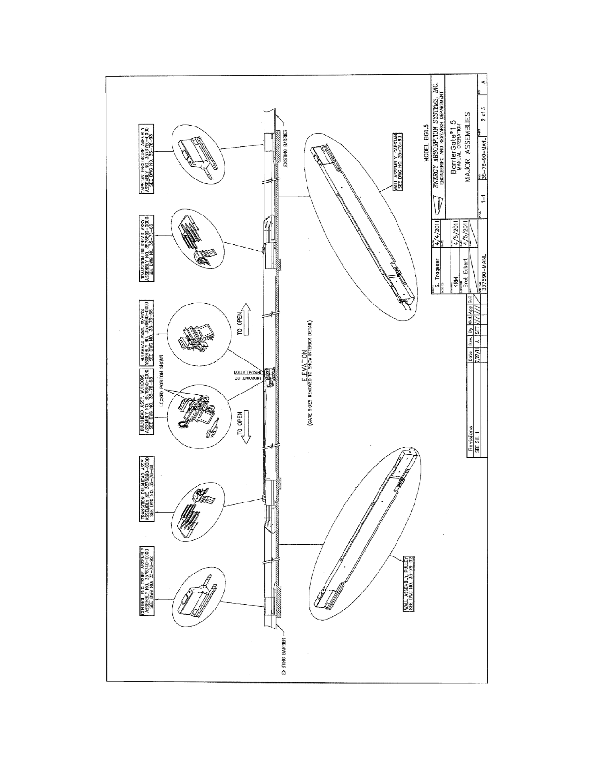
DWG 357690-MANL Sheet 2 of 3
www.energyabsorption.com Revision A May 2013
www.highwayguardrail.com 14 All rights in copyright reserved

DWG 357690-MANL Sheet 3 of 3
www.energyabsorption.com Revision A May 2013
www.highwayguardrail.com 15 All rights in copyright reserved

1.5
®
Concrete Pad, BarrierGate
DWG 277900-0000
www.energyabsorption.com Revision A May 2013
www.highwayguardrail.com 16 All rights in copyright reserved

y
1.5
®
, BarrierGate
Anchor Assembl
DWG 3576810-0000 Sheet 1 of 2
www.energyabsorption.com Revision A May 2013
www.highwayguardrail.com 17 All rights in copyright reserved

DWG 3576810-0000 Sheet 2 of 2
www.energyabsorption.com Revision A May 2013
www.highwayguardrail.com 18 All rights in copyright reserved

y
y
1.5
®
, BarrierGate
Pulle
Wall Assembl
DWG 357692 Sheet 1 of 2
www.energyabsorption.com Revision A May 2013
www.highwayguardrail.com 19 All rights in copyright reserved

DWG 357692 Sheet 2 of 2
www.energyabsorption.com Revision A May 2013
www.highwayguardrail.com 20 All rights in copyright reserved

®
1.5
Wall Assembly Capstan, BarrierGate
DWG 357693 Sheet 1 of 2
www.energyabsorption.com Revision A May 2013
www.highwayguardrail.com 21 All rights in copyright reserved

DWG 357693 Sheet 2 of 2
www.energyabsorption.com Revision A May 2013
www.highwayguardrail.com 22 All rights in copyright reserved

®
1.5
Track Assembly, BarrierGate
DWG 3576820-0000
www.energyabsorption.com Revision A May 2013
www.highwayguardrail.com 23 All rights in copyright reserved

y
1.5
®
, Hook Section, BarrierGate
Gate Assembl
DWG 3576680-0000 Sheet 1 of 2
www.energyabsorption.com Revision A May 2013
www.highwayguardrail.com 24 All rights in copyright reserved
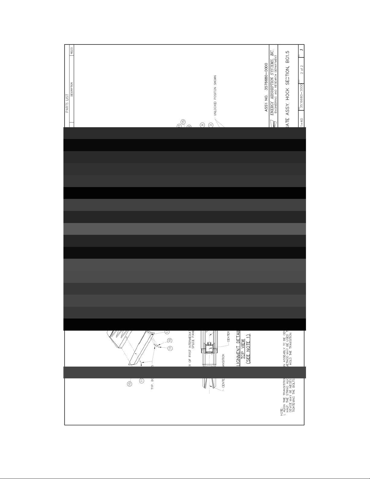
DWG 3576680-0000 Sheet 2 of 2
www.energyabsorption.com Revision A May 2013
www.highwayguardrail.com 25 All rights in copyright reserved
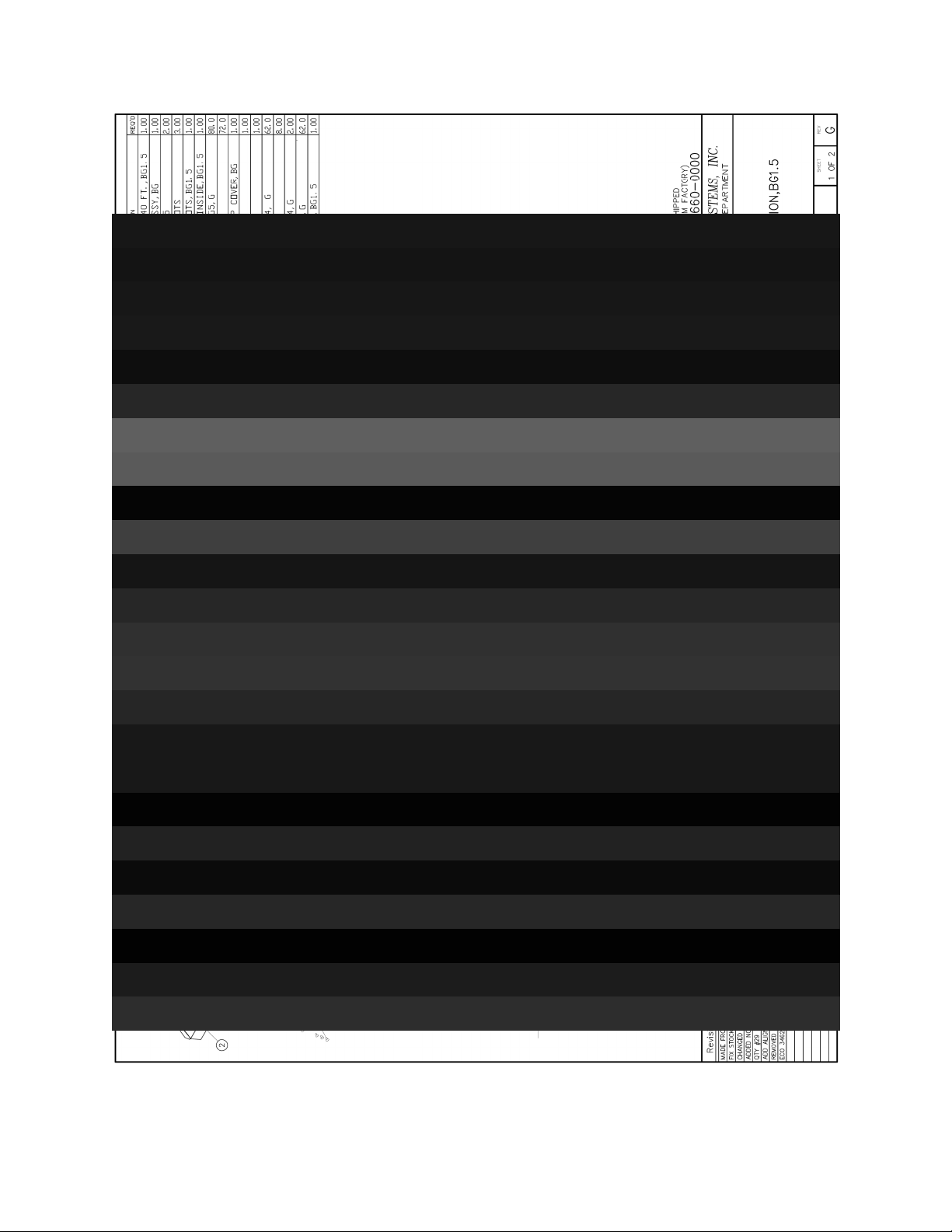
®
1.5
Gate Assembly, Pin Section, BarrierGate
DWG 3576660-0000 Sheet 1 of 2
www.energyabsorption.com Revision A May 2013
www.highwayguardrail.com 26 All rights in copyright reserved
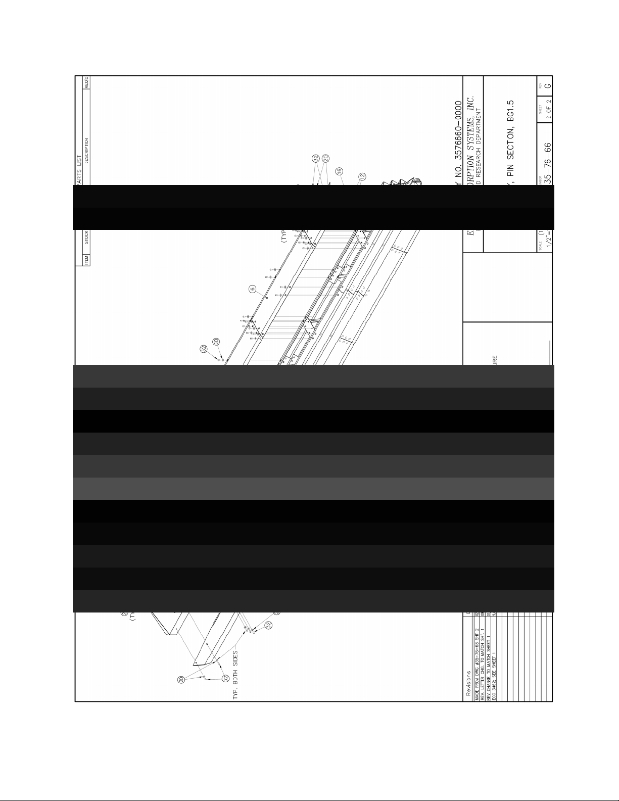
DWG 3576660-0000 Sheet 2 of 2
www.energyabsorption.com Revision A May 2013
www.highwayguardrail.com 27 All rights in copyright reserved
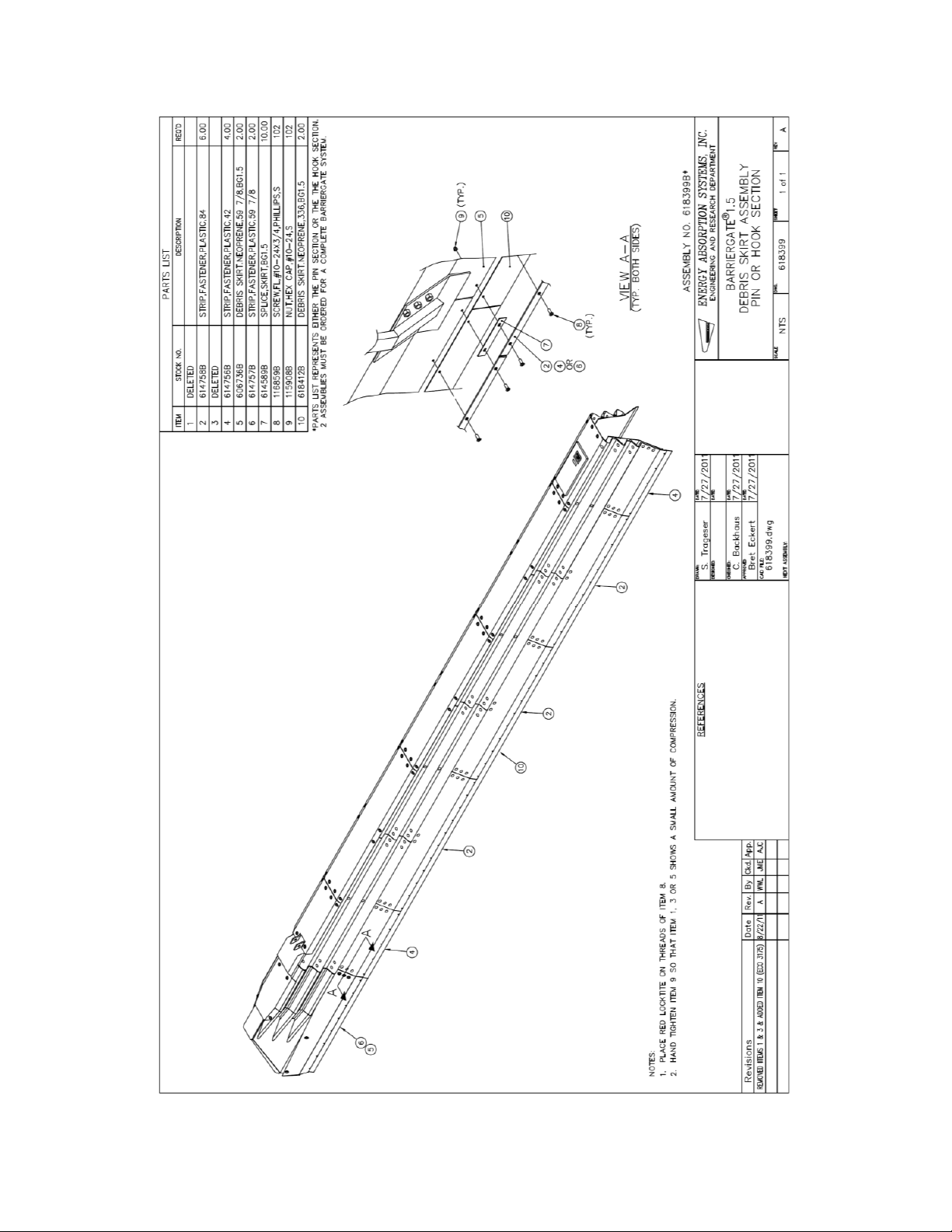
y
1.5
®
Pin or Hook Section, BarrierGate
Debris Skirt Assembl
DWG 618399
www.energyabsorption.com Revision A May 2013
www.highwayguardrail.com 28 All rights in copyright reserved

Notes:
www.energyabsorption.com Revision A May 2013
www.highwayguardrail.com 29 All rights in copyright reserved

Notes:
www.energyabsorption.com Revision A May 2013
www.highwayguardrail.com 30 All rights in copyright reserved

2525 Stemmons Freeway
Dallas, Texas 75207
888-323-6374 (USA only)
214-589-8140 (Outside USA)
www .energyabsorption.com
www.highwayguardrail.com
 Loading...