

Page 1

Thunderbolt®
NTP Time Server
TS200
For use with: Thunderbolt® NTP Time Server TS200 (P/N 111224-50)
Firmware version 1.0.0.0
Version IND8 - March 2018
Part Number 106131-50
Page 2

Legal Notices
Corporate Office
Trimble Inc.
935 Stewart Drive
Sunnyvale, California 94085 United
States of America.
www.trimble.com
Email: tsgsupport@trimble.com
Copyright and Trademarks
© 2018, Trimble Inc.
Trimble and the Globe & Triangle logo are trademarks of Trimble Inc.,
registered in the United States and in other countries.
Thunderbolt is a trademark of Trimble Inc..
Microsoft, Windows, and Windows Vista are either registered
trademarks or trademarks of Microsoft Corporation in the United
States and/or other countries.
All other trademarks are the property of their respective owners.
Release Notice
This is the March 2018 release of the Thunderbolt® NTP Time Server
, part number 111224-00.
Clock
The Australian Consumer Law
Our goods come with guarantees that cannot be excluded under the
Australian Consumer Law. You are entitled to a replacement or refund for
a major failure and for compensation for any other reasonably
foreseeable loss or damage. You are also entitled to have the goods
repaired or replaced if the goods fail to be of acceptable quality and the
failure does not amount to a major failure.
Trimble's warranty (set out below) is in addition to any mandatory
rights and remedies that you may have under the Australian
Consumer Law.
LIMITED WARRANTY TERMS AND CONDITIONS
Product Limited Warranty
Subject to the following terms and conditions, Trimble Inc. (“Trimble”)
warrants that for a period of one (1) year from date of purchase this
Trimble product (the “Product”) will substantially conform to Trimble's
publicly available specifications for the Product and that the hardware
and any storage media components of the Product will be substantially
free from defects in materials and workmanship..
Product Software
Product software, whether built into hardware circuitry as firmware,
provided as a standalone computer software product, embedded in flash
memory, or stored on magnetic or other media, is licensed solely for use
with or as an integral part of the Product and is not sold. If accompanied
by a separate end user license agreement (“EULA”), use of any such
software will be subject to the terms of such end user license agreement
(including any differing limited warranty terms, exclusions, and
limitations), which shall control over the terms and conditions set forth
herein.
Except for the limited license rights expressly provided herein, Trimble
and its suppliers have and will retain all rights, title and interest
(including, without limitation, all patent, copyright, trademark, trade
secret and other intellectual property rights) in and to the Product
Software and all copies, modifications and derivative works thereof
(including any changes which incorporate any of your ideas, feedback or
suggestions).
You shall not (and shall not allow any third party to): (a) decompile,
disassemble, or otherwise reverse engineer the Product Software or
attempt to reconstruct or discover any source code, underlying ideas,
algorithms, file formats or programming interfaces of the Product
Software by any means whatsoever (except and only to the extent that
applicable law prohibits or restricts reverse engineering restrictions); (b)
distribute, sell, sublicense, rent, lease, or use the Product Software (or
any portion thereof) for time sharing, hosting, service provider, or like
purposes; (c) remove any product identification, proprietary, copyright, or
other notices contained in the Product Software; (d) modify any part of
the Product Software, create a derivative work of any part of the Product
Software, or incorporate the Product Software into or with other
software, except to the extent expressly authorized in writing by Trimble;
(e) attempt to circumvent or disable the security key mechanism that
protects the Product Software against unauthorized use (except and only
to the extent that applicable law prohibits or restricts such restrictions);
or (f) publicly disseminate performance information or analysis (including,
without limitation, benchmarks) from any source relating to the Product
Software. If the Product Software has been provided to you as embedded
in any hardware device, you are not licensed to separate the Product
Software from the hardware device. If the Product Software has been
provided to you separately from a hardware device but is intended to be
loaded onto a hardware device specified by Trimble (such as a firmware
update), your license is limited to loading the Product Software on the
device specified by Trimble, and for no other use.
Software Fixes
During the limited warranty period you will be entitled to receive such Fixes
to the Product software that Trimble releases and makes commercially
available and for which it does not charge separately, subject to the
procedures for delivery to purchasers of Trimble products generally. If you
have purchased the Product from a Trimble authorized dealer rather than
from Trimble directly, Trimble may, at its option, forward the software Fix
to the Trimble authorized dealer for final distribution to you. Minor
Updates, Major Upgrades, new products, or substantially new software
releases, as identified by Trimble, are expressly excluded from this update
process and limited warranty. Receipt of software Fixes or other
enhancements shall not serve to extend the limited warranty period. For
purposes of this warranty the following definitions shall apply: (1) “Fix(es)”
means an error correction or other update created to fix a previous
software version that does not substantially conform to its Trimble
specifications; (2) “Minor Update” occurs when enhancements are made to
current features in a software program; and (3) “Major
Upgrade” occurs when significant new features are added to software, or
when a new product containing new features replaces the further
development of a current product line. Trimble reserves the right to
determine, in its sole discretion, what constitutes a Fix, Minor Update, or
Major Upgrade.
Warranty Remedies
If the Trimble Product fails during the warranty period for reasons covered
by this limited warranty and you notify Trimble of such failure during the
warranty period, Trimble will repair OR replace the nonconforming Product
with new, equivalent to new, or
Page | 2
Page 3

reconditioned parts or Product, OR refund the Product purchase price
paid by you, at Trimble’s option, upon your return of the Product in
accordance with Trimble's product return procedures then in effect.
How to Obtain Warranty Service
To obtain warranty service for the Product, please contact your local
Trimble authorized dealer. Alternatively, you may contact Trimble to
request warranty service by sending an email to
tsgsupport@trimble.com. Please prepare to provide:
– your name, address, and telephone numbers
– proof of purchase
– a copy of this Trimble warranty
– a description of the nonconforming Product including the model number
– an explanation of the problem
The customer service representative may need additional information
from you depending on the nature of the problem. Any expenses
incurred in the making of a claim under this warranty will be borne by
you.
Warranty Exclusions and Disclaimer
This Product limited warranty shall only apply in the event and to the
extent that: (a) the Product is properly and correctly installed, configured,
interfaced, maintained, stored, and operated in accordance with Trimble's
applicable operator's manual and specifications, and; (b) the Product is not
modified or misused.
This Product limited warranty shall not apply to, and Trimble shall not be
responsible for, defects or performance problems resulting from: (i) the
combination or utilization of the Product with hardware or software
products, information, data, systems, interfaces, or devices not made,
supplied, or specified by Trimble;
(ii) the operation of the Product under any specification other than, or in
addition to, Trimble's standard specifications for its products; (iii) the
unauthorized installation, modification, or use of the Product; (iv) damage
caused by: accident, lightning or other electrical discharge, fresh or salt
water immersion or spray (outside of Product specifications), or exposure to
environmental conditions for which the Product is not intended; (v) normal
wear and tear on consumable parts (e.g., batteries); or (vi) cosmetic
damage. Trimble does not warrant or guarantee the results obtained
through the use of the Product, or that software components will operate
error free.
NOTICE REGARDING PRODUCTS EQUIPPED WITH TECHNOLOGY CAPABLE
OF TRACKING SATELLITE SIGNALS FROM SATELLITE BASED
AUGMENTATION SYSTEMS (SBAS) (WAAS/EGNOS, AND MSAS),
OMNISTAR, GPS, MODERNIZED GPS OR GLONASS SATELLITES, OR FROM
IALA BEACON SOURCES: TRIMBLE IS NOT RESPONSIBLE FOR THE
OPERATION OR FAILURE OF OPERATION OF ANY SATELLITE BASED
POSITIONING SYSTEM OR THE AVAILABILITY OF ANY SATELLITE BASED
POSITIONING SIGNALS.
THE FOREGOING LIMITED WARRANTY TERMS STATE TRIMBLE’S ENTIRE
LIABILITY, AND YOUR EXCLUSIVE REMEDIES, RELATING TO THE TRIMBLE
PRODUCT UNDER THIS LIMITED WARRANTY. EXCEPT AS OTHERWISE
EXPRESSLY PROVIDED HEREIN, THE PRODUCT, AND ACCOMPANYING
DOCUMENTATION AND MATERIALS ARE PROVIDED “AS-IS” AND WITHOUT
EXPRESS OR IMPLIED WARRANTY OF ANY KIND, BY EITHER TRIMBLE OR
ANYONE WHO HAS BEEN INVOLVED IN ITS CREATION,
PRODUCTION, INSTALLATION, OR DISTRIBUTION, INCLUDING, BUT NOT
LIMITED TO, THE IMPLIED WARRANTIES OR GUARANTEES OF
MERCHANTABILITY, ACCEPTABILITY AND FITNESS FOR A PARTICULAR
PURPOSE, TITLE, AND NONINFRINGEMENT. THE
STATED EXPRESS WARRANTIES ARE IN LIEU OF ALL OBLIGATIONS OR
LIABILITIES ON THE PART OF TRIMBLE ARISING OUT OF, OR IN
CONNECTION WITH, ANY PRODUCT. BECAUSE SOME STATES AND
JURISDICTIONS DO NOT ALLOW LIMITATIONS ON DURATION OR THE
EXCLUSION OF AN IMPLIED WARRANTY, THE ABOVE LIMITATION MAY
NOT APPLY OR FULLY APPLY TO YOU.
Limitation of Liability
TO THE MAXIMUM EXTENT PERMITTED BY APPLICABLE LAW, TRIMBLE'S
ENTIRE LIABILITY UNDER ANY PROVISION HEREIN SHALL BE LIMITED TO
THE AMOUNT PAID BY YOU FOR THE PRODUCT ANDIN NO EVENT SHALL
TRIMBLE OR ITS SUPPLIERS BE LIABLE FOR ANY INDIRECT, SPECIAL,
INCIDENTAL, OR CONSEQUENTIAL DAMAGE WHATSOEVER UNDER ANY
CIRCUMSTANCE OR LEGAL THEORY RELATING IN ANYWAY TO THE
PRODUCTS, SOFTWARE AND ACCOMPANYING DOCUMENTATION AND
MATERIALS, (INCLUDING, WITHOUT LIMITATION, DAMAGES FOR LOSS OF
BUSINESS PROFITS, BUSINESS INTERRUPTION, LOSS OF DATA, OR ANY
OTHER PECUNIARY LOSS), REGARDLESS OF WHETHER TRIMBLE HAS BEEN
ADVISED OF THE POSSIBILITY OF ANY SUCH LOSS AND REGARDLESS OF
THE COURSE OF DEALING WHICH DEVELOPS OR HAS DEVELOPED
BETWEEN YOU AND TRIMBLE. BECAUSE SOME STATES AND
JURISDICTIONS DO NOT ALLOW THE EXCLUSION OR LIMITATION OF
LIABILITY FOR CONSEQUENTIAL OR INCIDENTAL DAMAGES, THE ABOVE
LIMITATION MAY NOT APPLY OR FULLY APPLY TO YOU.
PLEASE NOTE: THE ABOVE TRIMBLE LIMITED WARRANTY
PROVISIONS WILL NOT APPLY TO PRODUCTS
PURCHASED IN THOSE JURISDICTIONS (E.G., MEMBER STATES OF THE
EUROPEAN ECONOMIC AREA) IN WHICH PRODUCT WARRANTIES ARE
THE RESPONSIBILITY OF THE LOCAL TRIMBLE AUTHORIZED DEALER FROM
WHOM THE PRODUCTS ARE ACQUIRED. IN SUCH A CASE, PLEASE
CONTACT YOUR LOCAL TRIMBLE AUTHORIZED DEALER FOR APPLICABLE
WARRANTY INFORMATION.
Official Language
THE OFFICIAL LANGUAGE OF THESE TERMS AND CONDITIONS IS ENGLISH.
IN THE EVENT OF A CONFLICT BETWEEN ENGLISH AND OTHER LANGUAGE
VERSIONS, THE ENGLISH LANGUAGE SHALL CONTROL.
Registration
To receive information regarding updates and new products, please
contact your local Trimble authorized dealer or visit the Trimble website
at www.trimble.com/register. Upon registration you may select the
newsletter, upgrade, or new product information you desire.
Notices
Class B Statement – Notice to Users. This equipment has been tested and
found to comply with the limits for a Class B digital device, pursuant to Part
15 of the FCC rules. These limits are designed to provide reasonable
protection against harmful interference in a residential installation. This
equipment generates, uses, and can radiate radio frequency energy and, if
not installed and used in accordance with the instructions, may cause
harmful interference to radio communication. However, there is no
guarantee that interference will not occur in a particular installation. If this
equipment does cause harmful interference to radio or television reception,
which can be determined by turning the equipment off and on, the user is
encouraged to try to correct the interference by one or more of the
following measures:
Page | 3
Page 4

– Reorient or relocate the receiving antenna.
Declaration of Conformity
We, Trimble Inc.,
935 Stewart Drive
Sunnyvale, CA 94085-3913
United States of America
+1-408-481-8000
declare under sole responsibility that the
product: Thunderbolt® NTP Time Server Clock
complies with Part 15B of FCC Rules.
Operation is subject to the following two conditions:
(1) this device may not cause harmful interference,
and (2) this device must accept any interference
received, including interference that may cause
undesired operation.
– Increase the separation between the equipment and the receiver.
– Connect the equipment into an outlet on a circuit different from that to
which the receiver is connected.
– Consult the dealer or an experienced radio/TV technician for help.
Changes and modifications not expressly approved by the
manufacturer or registrant of this equipment can void your authority
to operate this equipment under Federal Communications
Commission rules.
Canada
This digital apparatus does not exceed the Class B limits for radio noise
emissions from digital apparatus as set out in the radio interference
regulations of the Canadian Department of Communications, ICES-003.
Le présent appareil numérique n’émet pas de bruits radioélectriques
dépassant les limites applicables aux appareils numériques de Classe B
prescrites dans le règlement sur le brouillage radioélectrique édicté par
le Ministère des Communications du Canada, ICES-003.
Europe
This product has been tested and found to comply with the
requirements for a Class B device pursuant to European Council
Directive 89/336/EEC on EMC, thereby satisfying the
requirements for CE Marking and sale within the European
Economic Area (EEA). These requirements are designed to provide
reasonable protection against harmful interference when the
equipment is operated in a residential or commercial
environment.
Notice to Our European Union Customers
For product recycling instructions and more information, please go to
www.trimble.com/ev.shtml.
Recycling in Europe: To recycle Trimble WEEE (Waste Electrical
and Electronic Equipment, products that run on electrical power.),
Call +31 497 53 24 30, and ask for the "WEEE Associate". Or, mail a
request for recycling instructions to:
Trimble Europe BV
c/o Menlo Worldwide Logistics Meerheide 45
5521 DZ Eersel, NL
Page | 4
Page 5

List of Abbreviations
A-GPS Assisted GPS
C/No Carrier-to-Noise power ratio
DC Direct Current
DOP Dilution of Precision
EGNOS European Geostationary Navigation Overlay Service
ESD Electrostatic Discharge
GLONASS Globalnaya Navigatsionnaya Sputnikovaya Sistema
GND Ground
GNSS Global Navigation Satellite Systems
GPS Global Positioning System
I/O Input / Output
LNA Low Noise Amplifier
NMEA National Marine Electronics Association
NTP Network Time Protocol. Common time distribution over networks.
OCXO Oven Controlled Crystal Oscillator
OD mode Over-determined clock mode
PoE Power over Ethernet
PCB Printed Circuit Board
PDOP Position Dilution of Precision
PPS Pulse per Second
QZSS Quasi-Zenith Satellite System
RF Radio Frequency
TCXO Temperature Controlled Crystal Oscillator
ToD Time of Day
T-R AIM Timing Receiver Autonomous Integrity Monitoring
T-S UTC Universal Time Coordinated
VCC Voltage at the Common Collector; positive supply voltage
VSWR Voltage Standing Wave Ratio
Page | 5
Page 6

Safety Information
Warnings and Cautions
An absence of specific alerts does not mean that there are no safety risks involved. Always follow the
instructions that accompany a Warning or Caution. The information they provide is intended to minimize
the risk of personal injury and/or damage to the equipment. In particular, observe safety instructions that
are presented in the following formats:
WARNING – A Warning alerts you to a likely risk of serious injury to your person and/or damage to the equipment.
CAUTION – A Caution alerts you to a possible risk of damage to the equipment and/or loss of data.
CAUTION – Electrical hazard – risk of damage to equipment. Make sure all electrostatic energy is dissipated before
installing or removing components from the device. An electrostatic discharge (ESD) can cause serious damage to
the component once it is outside the chassis
Operation and storage
WARNING – Operating or storing the Thunderbolt® NTP Time Server Clock outside the specified temperature range can damage
it. For more information, see the product specifications on the data sheet.
WARNING – The Thunderbolt® NTP Time Server Clock is only to be used in a restricted access location
WARNING – Short-circuit (overcurrent) protection device required. The Thunderbolt® NTP Time Server Clock relies on the
building’s installation for short-circuit (overcurrent) protection. Ensure that the protective device is listed rated not greater than
10A
Routing any cable
CAUTION – Be careful not to damage the cable. Take care to avoid sharp bends or kinks in the cable, hot surfaces (for example,
exhaust manifolds or stacks), rotating or reciprocating equipment, sharp or abrasive surfaces, door and window jambs, and
corrosive fluids or gases.
Page | 6
Page 7

Table of Contents
Contents
Legal Notices ................................................................................................................................................... 2
List of Abbreviations ....................................................................................................................................... 5
Safety Information .......................................................................................................................................... 6
Warnings and Cautions ............................................................................................................................... 6
Operation and storage ................................................................................................................................ 6
Routing any cable ........................................................................................................................................ 6
Table of Contents ............................................................................................................................................ 7
Chapter 1: Product Overview ....................................................................................................................... 15
1.1 Product Overview ............................................................................................................................... 16
1.2 Key Features ........................................................................................................................................ 16
1.3 Physical Specifications ........................................................................................................................ 16
1.4 Performance ....................................................................................................................................... 17
1.5 Front Panel Elements .......................................................................................................................... 17
EIA-232 Serial Port ................................................................................................................................ 17
Sync Out ................................................................................................................................................ 17
Status LED ............................................................................................................................................. 17
Management Port (LAN) ....................................................................................................................... 17
Ethernet Port......................................................................................................................................... 17
SFP Port ................................................................................................................................................. 17
1.6 Back Panel Elements ........................................................................................................................... 18
GNSS Antenna Connection .................................................................................................................... 18
Power Input ........................................................................................................................................... 18
Alarm Relay ........................................................................................................................................... 18
Grounding ............................................................................................................................................. 18
1.7 Use and care........................................................................................................................................ 18
1.8 Technical assistance
........................................................................................................................... 19
Chapter 2: Installation .................................................................................................................................. 21
2.1 Getting Started .................................................................................................................................... 22
Page | 7
Page 8

2.2 Mounting the Device to a Rack ........................................................................................................... 22
2.3 Connecting Power ............................................................................................................................... 22
Grounding the Device ........................................................................................................................... 23
Powering-Up ......................................................................................................................................... 23
2.4 GNSS Considerations ........................................................................................................................... 23
Selecting Site for GNSS Antenna ........................................................................................................... 24
2.5 Communication Ports ......................................................................................................................... 25
Serial Port .............................................................................................................................................. 25
Management Ethernet Port .................................................................................................................. 26
NTP Electrical Ethernet Port ................................................................................................................. 26
NTP SFP Ethernet Port .......................................................................................................................... 26
2.6 Status LED ........................................................................................................................................... 27
Chapter 3: GNSS Antenna ............................................................................................................................. 29
3.1 GNSS Antenna ..................................................................................................................................... 30
Antenna requirements .......................................................................................................................... 30
3.2 Antenna Placement ............................................................................................................................. 30
Sky-Visibility .......................................................................................................................................... 30
Multipath-reflections ............................................................................................................................ 31
Jamming ................................................................................................................................................ 31
Ground Plane ........................................................................................................................................ 31
GNSS Antenna Cabling .......................................................................................................................... 31
Lightning Considerations....................................................................................................................... 32
Chapter 4: Command Line Interface Reference ........................................................................................... 33
4.1 CLI Overview ....................................................................................................................................... 34
4.2 Command User Levels ......................................................................................................................... 34
4.3 Command Line Format ........................................................................................................................ 34
4.4 CLI Command Set ................................................................................................................................ 35
4.4.1 get alarm ...................................................................................................................................... 35
4.4.2 set alarm ...................................................................................................................................... 35
4.4.3 view alarm .................................................................................................................................... 36
4.4.4 view access ................................................................................................................................... 36
4.4.5.0 get auth ..................................................................................................................................... 36
4.4.5.1 get auth local............................................................................................................................. 36
Page | 8
Page 9

4.4.5.2 get auth tacacs .......................................................................................................................... 37
4.4.5.3 get auth radius .......................................................................................................................... 37
4.4.6.0 set auth ..................................................................................................................................... 37
4.4.6.1 set auth radius .......................................................................................................................... 38
4.4.6.2 set auth tacacs .......................................................................................................................... 38
4.4.6.3 set auth local ............................................................................................................................. 39
4.4.6.4 set auth type ............................................................................................................................. 40
4.4.7 get auto ........................................................................................................................................ 41
4.4.8 set auto ........................................................................................................................................ 41
4.4.9.0 config ......................................................................................................................................... 41
4.4.9.1 config firmware ......................................................................................................................... 42
4.4.9.2 config firmware list ................................................................................................................... 42
4.4.9.3 config firmware stage ............................................................................................................... 42
4.4.9.4 config firmware update ............................................................................................................ 43
4.4.9.5 config firmware unstage ........................................................................................................... 43
4.4.9.6 config load ................................................................................................................................. 44
4.4.9.7 config list ................................................................................................................................... 44
4.4.9.8 config save ................................................................................................................................ 44
4.4.9.9 config system ............................................................................................................................ 45
4.4.10 get comm ................................................................................................................................... 45
4.4.11 set comm .................................................................................................................................... 45
4.4.12 get date ...................................................................................................................................... 46
4.4.13 get dlog ...................................................................................................................................... 46
4.4.14 set dlog ....................................................................................................................................... 46
4.4.15 download ................................................................................................................................... 47
4.4.16 get freq ....................................................................................................................................... 47
4.4.17 set freq ....................................................................................................................................... 47
4.4.18 view freq .................................................................................................................................... 48
4.4.19 get gnss ...................................................................................................................................... 48
4.4.20 set gnss ....................................................................................................................................... 48
4.4.21 view gnss .................................................................................................................................... 49
4.4.22 help ............................................................................................................................................ 50
4.4.23 howto ......................................................................................................................................... 50
Page | 9
Page 10

4.4.24 get input ..................................................................................................................................... 51
4.4.25 set input ..................................................................................................................................... 51
4.4.26 view input................................................................................................................................... 52
4.4.27 view logs ..................................................................................................................................... 53
4.4.28 get network ................................................................................................................................ 54
4.4.29 set network ................................................................................................................................ 54
4.4.30 view network ............................................................................................................................. 55
4.4.31 get ntp ........................................................................................................................................ 56
4.4.32 set ntp ........................................................................................................................................ 56
4.4.33 view ntp...................................................................................................................................... 57
4.4.34 get output .................................................................................................................................. 58
4.4.35 set output ................................................................................................................................... 58
4.4.36 get periodic ................................................................................................................................ 59
4.4.37 set periodic................................................................................................................................. 59
4.4.38 ping............................................................................................................................................. 59
4.4.39 ping6 .......................................................................................................................................... 60
4.4.40 view pos ..................................................................................................................................... 60
4.4.41 view prodconf ............................................................................................................................ 60
4.4.45 quit ............................................................................................................................................. 61
4.4.46 view realtime ............................................................................................................................. 61
4.4.47 help set ....................................................................................................................................... 61
4.4.48 get snmp .................................................................................................................................... 61
4.4.49 set snmp ..................................................................................................................................... 62
4.4.50 view summary ............................................................................................................................ 62
4.4.51 view stream ................................................................................................................................ 62
4.4.52 get syslog .................................................................................................................................... 63
4.4.53 set syslog .................................................................................................................................... 63
4.4.54 view temp .................................................................................................................................. 64
4.4.55 get time ...................................................................................................................................... 64
4.4.56 view uptime ............................................................................................................................... 64
4.4.57 get user ...................................................................................................................................... 64
4.4.58 set user ....................................................................................................................................... 65
4.4.59 set user logout ........................................................................................................................... 66
Page | 10
Page 11

4.4.60 view user .................................................................................................................................... 66
4.4.61 view version ............................................................................................................................... 66
4.4.62.0 view ......................................................................................................................................... 67
4.4.62.1 view gnss stream ..................................................................................................................... 68
4.4.62.2 view dlog ................................................................................................................................. 68
4.4.63 whatif ......................................................................................................................................... 68
4.5 List of “How to” help topics ................................................................................................................ 68
4.5.1 How to get current Alarm status? ................................................................................................ 69
4.5.2 How to set alarm of level major, alarm number 2 with setTime as 2 and clearTime as 1? ......... 69
4.5.3 How to disable Ethernet port 0/1? ............................................................................................. 69
4.5.4 How to set ip address of 192.168.0.9, and also set a netmask and a gateway address on
ethernet 0 port? .................................................................................................................................... 69
4.5.5 How to set bnc output of even? .................................................................................................. 69
4.5.6 How to set periodic output of period 2 and value 1? .................................................................. 69
4.5.7 How to set serial port baud rate to 19200bps? ........................................................................... 69
4.5.8 How to add a new user called trimble1 with an access level of user? ........................................ 70
4.5.9 How to delete an existing user trimble? ...................................................................................... 70
4.5.10 How to change user password? ................................................................................................. 70
4.5.11 How to restore factory default settings? ................................................................................... 70
4.5.12 How to reboot the system? ....................................................................................................... 70
4.6 List of “What if” help topics ................................................................................................................ 71
4.6.1 What if you have an FPGA-Load-Bad alarm ................................................................................. 71
Chapter 5: Web Interface ............................................................................................................................. 73
5.1 Home Page .......................................................................................................................................... 74
Refresh Rate .......................................................................................................................................... 74
5.2 Login Page ........................................................................................................................................... 75
5.3 System Page ........................................................................................................................................ 76
5.4 System Status ...................................................................................................................................... 76
Alarms and Events - Alarms .................................................................................................................. 76
Alarms and Events – Event Log ............................................................................................................. 77
System Info ........................................................................................................................................... 78
Timing Status ......................................................................................................................................... 79
NTP Status ............................................................................................................................................. 81
Page | 11
Page 12

GNSS Receiver Status ............................................................................................................................ 82
Satellite Data ......................................................................................................................................... 83
Network eth0 ........................................................................................................................................ 84
Network eth1 ........................................................................................................................................ 85
Network Management Port .................................................................................................................. 86
Ethernet Statistics ................................................................................................................................. 87
5.5 Interface Management ....................................................................................................................... 88
IP Assignment eth0 ............................................................................................................................... 88
IP Assignment eth1 ............................................................................................................................... 89
IP Assignment management port ......................................................................................................... 90
VLAN eth0 ............................................................................................................................................. 91
VLAN eth1 ............................................................................................................................................. 92
SNMP Configuration Basic .................................................................................................................... 93
SNMP Configuration v2c ....................................................................................................................... 94
Syslog .................................................................................................................................................... 95
Serial Port .............................................................................................................................................. 96
5.6 Synchronization Management ............................................................................................................ 97
NTP Time Server eth0 ........................................................................................................................... 97
NTP Time Server eth1 ........................................................................................................................... 98
NTP Time Server - NTP security ............................................................................................................ 99
NTP Time Server - NTP Peers .............................................................................................................. 100
GNSS Receiver ..................................................................................................................................... 101
Output Configuration .......................................................................................................................... 102
5.7 Security Management ....................................................................................................................... 103
User Management - Active Sessions ................................................................................................... 103
User Management - User Accounts .................................................................................................... 104
User Management – Password Rules ................................................................................................. 105
Authentication Portal .......................................................................................................................... 106
Authentication RADIUS ....................................................................................................................... 107
Authentication TACACS+ ..................................................................................................................... 108
5.8 System Management ........................................................................................................................ 109
Alarm Configuration ............................................................................................................................ 109
System Configuration .......................................................................................................................... 110
Page | 12
Page 13

System Software Upload ..................................................................................................................... 111
Chapter 6: SNMP Support ........................................................................................................................... 113
6.1 SNMP Overview ................................................................................................................................ 114
6.2 SNMP Traps ....................................................................................................................................... 114
6.3 Accessing the SNMP MIB Files .......................................................................................................... 114
Chapter 7: TS200 Provisioning .................................................................................................................... 115
7.1 Help Commands ................................................................................................................................ 116
7.1.1 help set ....................................................................................................................................... 116
7.1.2 help set ntp ................................................................................................................................ 117
7.2 View System and Hardware Version ................................................................................................. 119
7.2.1 view version ............................................................................................................................... 119
7.2.2 view prodconf ............................................................................................................................ 120
7.3 View Alarms, Status and Firmware ................................................................................................... 121
7.3.1 get alarm .................................................................................................................................... 121
7.3.2 view logs ..................................................................................................................................... 122
7.4 GNSS and Lock Status ........................................................................................................................ 124
7.4.1 view gnss .................................................................................................................................... 124
7.4.2 get gnss ...................................................................................................................................... 125
7.4.3 view freq .................................................................................................................................... 126
7.5 Network Configuration ..................................................................................................................... 127
7.5.1 get network ................................................................................................................................ 127
7.5.2 set network ................................................................................................................................ 128
7.5.3 get network eth<x> .................................................................................................................... 129
7.5.4 view network eth<x> ................................................................................................................. 130
7.6 VLAN Configuration ........................................................................................................................... 131
7.6.1 set network eth0 vlan ................................................................................................................ 131
7.6.2 get network eth0........................................................................................................................ 132
7.6.3 set network eth0.20 ................................................................................................................... 133
7.6.4 get network eth0........................................................................................................................ 134
7.8 Input Clock Source Control ............................................................................................................... 135
7.8.1 get input ..................................................................................................................................... 135
7.8.2 set input ..................................................................................................................................... 135
7.8.3 view input................................................................................................................................... 136
Page | 13
Page 14

7.9 Antenna Cable Delay and BNC Port Output ...................................................................................... 137
7.9.1 set gnss adelay 40 ...................................................................................................................... 137
7.9.2 set output 10Mhz ....................................................................................................................... 138
7.9.3 config firmware list .................................................................................................................... 139
Chapter 8: VLANs ........................................................................................................................................ 141
8.1 VLANs Overview ................................................................................................................................ 143
8.2 Configuring VLAN support with CLI commands ................................................................................ 143
8.3 Configuring VLAN with Web Interface .............................................................................................. 144
8.4 Configuring one VLAN ID ................................................................................................................... 145
8.5 Adding another VLAN ID ................................................................................................................... 146
8.6 Procedure to remove all VLAN IDs .................................................................................................... 148
Appendix A: SNMP Traps ............................................................................................................................ 150
Appendix B: Alarms ..................................................................................................................................... 154
Contact Information .................................................................................................................................... 162
Page | 14
Page 15

User Guide Thunderbolt® NTP TS200 Time Server Clock
P a g e | 15
C H A P T E R
1
Chapter 1: Product Overview
In this chapter:
Operation
Key Features
Getting started
Use and care
Technical assistance
The Thunderbolt® NTP Time Server
Clock TS200 is a NTP Time Server. It
provides very accurate NTP time
reference.
The Thunderbolt® NTP Time Server Clock
TS200’s User Guide describes how to
integrate and operate the Trimble
Thunderbolt® NTP Time Server Clock TS200.
For more information on GPS, go to
http://www.trimble.com/gps/index.shtml.
®
Page 16

User Guide Thunderbolt® NTP TS200 Time Server Clock
P a g e | 16
1.1 Product Overview
Trimble’s Thunderbolt® NTP Time Server Clock TS200 is a high quality NTP Time Server Clock
with an integrated Trimble GNSS receiver with the best accurate and reliable technology. The
Thunderbolt® TS200 is designed and optimized for low latency applications such as high
frequency trading, providing the highest performance to meet the stringent time & phase
requirements.
It provides NTP timing protocol. Thunderbolt® TS200 uses GNSS (Global Navigation Satellite
Systems) signals from GPS, GLONASS, Galileo, and Beidou as the primary time source for
synchronization.
Thunderbolt® TS200 can use its built-in, disciplined OCXO (oven controlled crystal oscillator) as
autonomous time base for providing several hours of accurate holdover in case that GNSS
signals are not available.
Hardware redundancy can be achieved by using two Thunderbolt® NTP Time Server clocks.
Thunderbolt® TS200 comes in a rack-mountable enclosure; two Thunderbolt® TS200 units fit
side- by-side in a 1RU height 19” rack.
1.2 Key Features
Network Time Server (NTP v4)
Multi-GNSS Receiver (GPS, GLONASS, Beidou and Galileo)
1 RJ45 Dedicated Management Port
1 RJ45 Port (NTP)
1 SFP interface (NTP)
1 BNC interface (PPS/10MHz outputs
IPv4, IPv6 and VLAN
1 EIA-232 (RS-232) Serial Port
Small foot print – ½ Rack 1U
CLI / SNMP traps
DC (default) and AC power options
1.3 Physical Specifications
The Thunderbolt® TS200 can be installed in a 19-inch rack mount unit. It can fit in ½ rack
space, 2 Thunderbolt® TS200 units can be installed side-by-side in a full rack space for
additional redundancy.
Page 17
User Guide Thunderbolt® NTP TS200 Time Server Clock
P a g e | 17
1.4 Performance
The system level performance is defined by the total number of packets per second. The
total/maximum number of packets per second supported is 6,272.
Thunderbolt® NTP Time Server TS200 can support 2,500 NTP transactions per second.
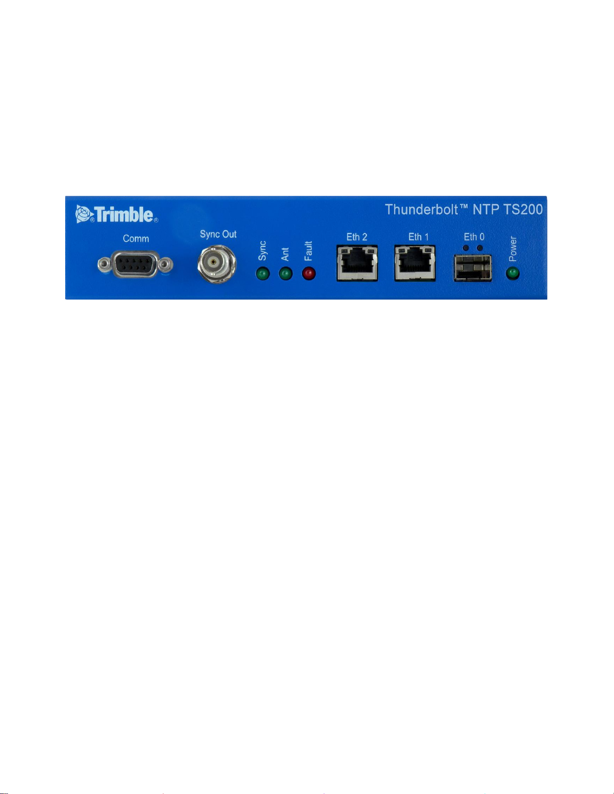
1.5 Front Panel Elements
EIA-232 Serial Port
The EIA-232 (RS-232) serial port provides a craft interface to the Thunderbolt® NTP Time
Server TS200 through an EIA-232 female connector.
Sync Out
The Thunderbolt® TS200 features a BNC female connector that provides 1PPS output. It can be
configured for 10MHz, see the set output command.
Status LED
The Thunderbolt® NTP TS200 provides 4 LEDs on the front panel that indicate the following
status:
Power
Antenna
Sync
Status/Alarm
Management Port (LAN)
The Thunderbolt® TS200 has one dedicated management Ethernet port. The RJ-45 port
provides connectivity to Ethernet LAN for the configuration of the unit.
Ethernet Port
One RJ45 Ethernet port. Provides NTP connectivity to Ethernet Networks
SFP Port
One SFP port. Provides NTP connectivity to Ethernet Networks.
Page 18

User Guide Thunderbolt® NTP TS200 Time Server Clock
P a g e | 18
1.6 Back Panel Elements
GNSS Antenna Connection
The Thunderbolt® NTP Time Server TS200 features an SMA connector for the antenna input to
the embedded GNSS receiver
Power Input
The standard input power is -48VDC. The Thunderbolt® TS200 provides a 5pole terminal
block to connect dual DC power inputs.
Alarm Relay
The Thunderbolt® TS200 provides a 3.81mm 3pin terminal header for dry relay connection. Both
Normally Open (NO) and Normally Closed (NC) connections are available to the user. Relay
closure is considered closed in Critical alarm condition.
Grounding
The frame ground connection on Thunderbolt® TS200 is available through a M5 Grounding
Terminal Stud.
1.7 Use and care
The Thunderbolt® TS200 is a high-precision electronic instrument and should be treated with
reasonable care. Thunderbolt® TS200 typically doesn’t need any care after the first setup.
Should you need to clean the unit, use a dry non-static tissue or a light moist tissue for
removing dust or stain from the enclosure. Make sure that no water enters the Thunderbolt®
TS200 enclosure anywhere. Don’t use solvents, aggressive or abrasive cleaning agents
anywhere on the Thunderbolt® TS200 device.
CAUTION – There are no user-serviceable parts inside the Thunderbolt® NTP Time Server
Clock TS200 and any modification to the unit by the user voids the warranty.
Page 19

User Guide Thunderbolt® NTP TS200 Time Server Clock
P a g e | 19
1.8 Technical assistance
If you have a problem and cannot find the information you need in the product documentation,
contact the Trimble Technical Assistance Center at 800-767-4822 or email
tsgsupport@trimble.com.
Page 20

User Guide Thunderbolt® NTP TS200 Time Server Clock
P a g e | 20
Page 21

User Guide Thunderbolt® NTP TS200 Time Server Clock
P a g e | 21
C H A P T E R
2
Chapter 2: Installation
In this chapter:
Getting Started
Time References
Operation
Timing module Performance
Holdover
Customization
This chapter describes the procedure for
installing the Thunderbolt® NTP Time
Server Clock TS200.
Page 22

User Guide Thunderbolt® NTP TS200 Time Server Clock
P a g e | 22
2.1 Getting Started
This section explains how to install and configure the Thunderbolt TS200.
Unpack and inspect the content of package. The following items are included in the standard box:
Thunderbolt NTP Time Server Clock TS200
Mounting brackets and installation accessories
Dummy plate for single unit installation in 19” rack
2.2 Mounting the Device to a Rack
The Thunderbolt NTP TS200 should be installed indoor or outdoor in an environmental controlled
cabinet. The Thunderbolt TS200 will install in an EIA standard 19-inch rack. The unit occupies ½
rack space and if required two TS200 units can be installed side-by-side.
NOTE – It is recommended that 1 rack-unit of space (1.75 in) be kept empty above the device. This
allows a small amount of convectional airflow. Forced airflow is not required.
2.3 Connecting Power
The Thunderbolt TS200 supports single or dual redundant AC or DC power supplies. The
Thunderbolt TS200 standard option is 48VDC. The Thunderbolt TS200 is capable of operating
from -36Vdc to -72Vdc at a maximum current level of 250mA.
The DC input is reverse polarity protected. Reversing polarity with 48VDC options will not cause
damage to the unit and the unit will operate normally.
NOTE – The power cable should be routed separately from the data (signal) cables.
Page 23

User Guide Thunderbolt® NTP TS200 Time Server Clock
P a g e | 23
Grounding the Device
The Thunderbolt TS200 M5 Terminal Stud on the back panel is used for grounding.
The Thunderbolt TS200 is suitable for connection to the Central Office and CPE. The Time
Server Clock shall be located in a restricted access location where only crafts personnel are
allowed access.
The Thunderbolt TS200 shall be grounded via a copper ground conductor. The unit shall be
installed and connected to the common bonding network (CBN).
All bare grounding connection points to the Thunderbolt TS200 shall be cleaned and coated
with an anti-oxidant solution before connections are made.
All surfaces on the Thunderbolt TS200 that are un-plated shall be brought to a bright finish
and treated with and anti-oxidant solution before connection is made.
All non-conductive surfaces on the Thunderbolt TS200 shall be removed from all threads and
connection points to ensure electrical continuity
The Thunderbolt TS200 DC power returns shall be treated as DC-I (Isolated from Frame
Ground).
Thunderbolt TS200 requires a ring terminal with a 14-AWG wire that utilizes 15in-lbs to
secure to primary ground.
Powering-Up
After verification of the input power source, switch on the power supply to the Thunderbolt
TS200. The Green Power LED should turn ON.
2.4 GNSS Considerations
See the next chapter for a full description of how to choose the correct antenna cable/antenna
combination.
When connected to a GNSS antenna the Thunderbolt TS200 can receive GNSS signal without
user intervention– the factory default is GPS and GLONASS. The user can enable Beidou in place
of GLONASS or enable single constellation mode.
Page 24

User Guide Thunderbolt® NTP TS200 Time Server Clock
P a g e | 24
The Trimble family of Bullet antennas is best matched with Thunderbolt TS200. The bullet
antenna has following versions:
Bullet III GPS only antenna
Bullet GG GPS and GLONASS antenna
Bullet L1/L2 GPS Dual Band – L1 and L2 frequencies
Bullet 40dB GPS L1 high gain (40dB) antenna
Bullet GB GPS and Beidou antenna
Bullet 360 GPS, GLONASS, Beidou and Galileo antenna
Connecting the GNSS antenna will turn the Antenna LED Green.
Selecting Site for GNSS Antenna
It is important that the GNSS antenna has the fullest possible view of the sky. In most cases, this
means installing the antenna on a high point, such as roof top. Avoid overhanging objects such
as trees and towers. Also take care to place the antenna away from low lying objects such as
neighboring buildings that may block a portion of the sky near the horizon. If a full view of the
sky is not possible, mount the antenna aiming towards the Equator to maximize the southern
view of the sky (choose a northern view in the Southern Hemisphere).
Use the criteria below to select a good outdoor site for the GPS antenna. The best locations
provide:
Unobstructed views of the sky and horizon.
Low electro-magnetic interference (EMI) and radio frequency interference (RFI) –
away from high-power lines, transmitting antennas, and powerful electrical
equipment.
Convenient access for installation and maintenance.
Reasonable access for the antenna cable to reach the Thunderbolt TS200
Page 25
User Guide Thunderbolt® NTP TS200 Time Server Clock
P a g e | 25
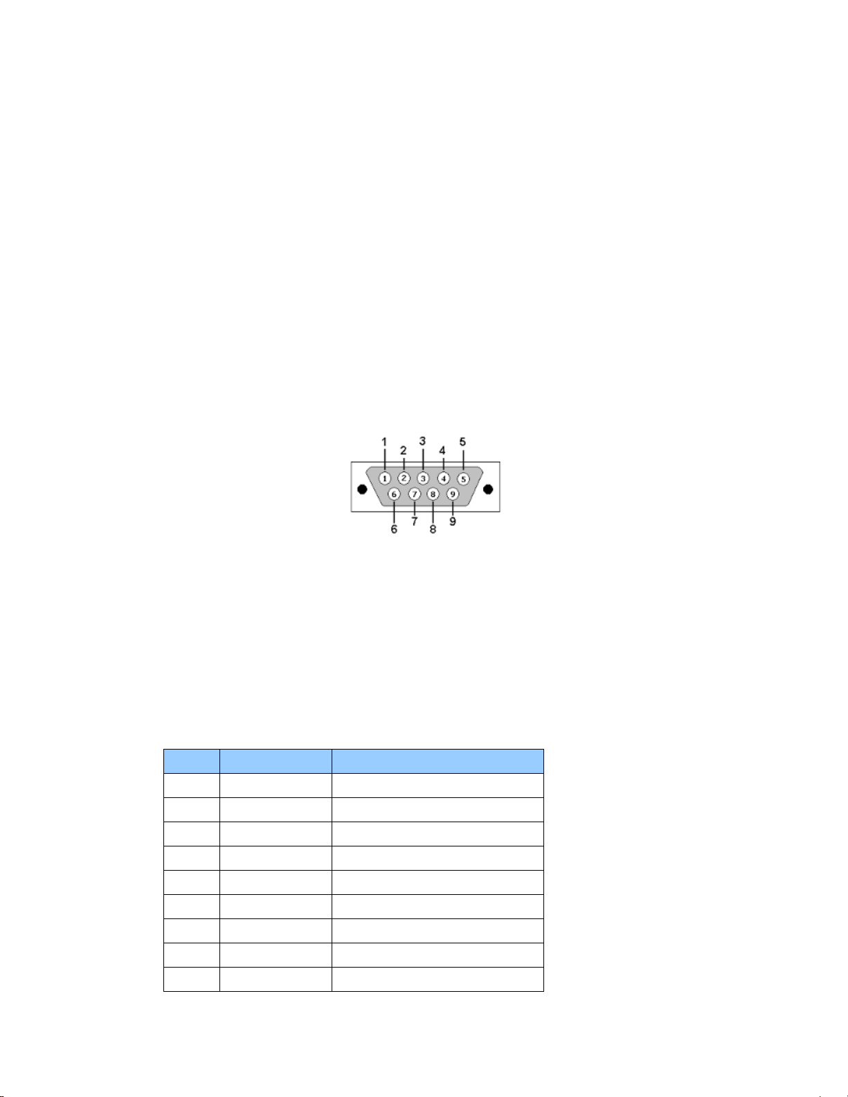
Pin
RS-232 Signal
Description on Echo Side
1
DCD
Not Used
2
RxD
Data Transmit
3
TxD
Data Receive
4
DTR
Not Used
5
GND
Ground
6
DSR
Not Used
7
RTS
Not Used
8
CTS
Not Used
9
RI
Not Used
2.5 Communication Ports
The Thunderbolt TS200 has four communications ports on the front panel.
1 Serial Port (RS232)
1 Management Port Ethernet (eth2) 10/100/1000 Base-T (RJ-45)
1 NTP Time Server Port Ethernet (eth1) 10/100/1000 Base-T (RJ-45)
1 NTP Time Server Port SFP (Small Form-Factor Pluggable)
Either Serial port or Ethernet eth2 (RJ-45) is the dedicated management port to configure
the Thunderbolt NTP Time Server TS200.
Serial Port
A bi-directional EIA standard RS-232 is located on the front panel. The serial port provides
access to command line interface (CLI) for limited status and configuration of the
Thunderbolt TS200.
Figure 2.1: Serial Port pin assignments
Use a straight through cable with following setting:
Data Rate 115200 baud
Parity None
Data Bits 8
Stop Bits 1
Serial Port Pin Assignment
Page 26

User Guide Thunderbolt® NTP TS200 Time Server Clock
P a g e | 26
IP Address:
192.168.2.250
Mask:
255.255.255.0
Gateway:
0.0.0.0
IP Address:
192.168.1.250
Mask:
255.255.255.0
Gateway:
0.0.0.0
Management Ethernet Port
The Thunderbolt TS200 supports one 10/100/1000 Base-T Ethernet port that allows
connection to standard CAT-5 / CAT-5e / CAT-6 cables with RJ-45 male connector.
The Ethernet port features an LED that indicates the state of the port. The port is designated
as “Ethernet-2”. The user can use this port to gain access to the Web interface (HTTPS) or
command line interface (TELNET/SSH).
The factory default settings for the Ethernet-2 network port are as follows:
NTP Electrical Ethernet Port
The Thunderbolt NTP TS200 supports one 10/100/1000 Base-T Ethernet port that allows
connection to standard CAT-5 / CAT-5e / CAT-6 cables with RJ-45 male connector.
The Ethernet port features an LED that indicates the state of the port. The port is designated
as “Ethernet-1”. This port is not designed for communication purposes for security reasons.
This port is designed for providing NTP.
The factory default settings for the Ethernet-1 network port are as follows:
NOTE – The Ethernet interface shall not be connected to a cable longer than 6 meters. If a distance
greater than 6 meters is required, then the Ethernet interface shall be connected to a switch to
comply with GR-1089.
NTP SFP Ethernet Port
The Thunderbolt NTP Time Server Clock TS200 supports one 10/100/1000 Base-T Ethernet
port that allows connection to standard CAT-5 / CAT-5e / CAT-6 cables with electrical SFP or
fiber cables with optical SFP.
The Ethernet port features an LED that indicates the state of the port. The port is designated
as “Ethernet-0”. This port is not designed for communication purposes for security reasons.
This port is designed for providing NTP.
Page 27

User Guide Thunderbolt® NTP TS200 Time Server Clock
P a g e | 27
IP Address:
192.168.0.250
Mask:
255.255.255.0
Gateway:
0.0.0.0
LED
Color
Indication
Meaning
Power
Green
ON
System is powered on
OFF
System does not have power
ANT
Green
ON
Reference acquired & tracking
Blinking, 1/2Hz
Reference being acquired, or no computing
OFF
No reference active or antenna
Sync
Green
ON
Locked
Blinking, 1/2Hz
Acquisition or Holdover
OFF
Free-run or startup
Status
Red
OFF
No active alarms
ON
Critical Alarm
Blink, 1Hz
Minor alarm condition
Blink, 1/2Hz
Major alarm condition
The factory default settings for the Ethernet-0 network port are as follows:
2.6 Status LED
Alarm and status information is presented through the use of four LEDs. All LEDs have
corresponding dry contact relay outputs at the back side of the Thunderbolt® TS200 device.
Page 28

User Guide Thunderbolt® NTP TS200 Time Server Clock
P a g e | 28
Page 29

User Guide Thunderbolt® NTP TS200 Time Server Clock
P a g e | 29
C H A P T E R
3
Chapter 3: GNSS Antenna
In this
chapter:
Antenna Requirements
OPEN/SHORT Detection
Antenna Placement
Multipath
A good GNSS antenna, together with a good
installation site, is the key for getting the
best performance from a GNSS receiver.
This chapter explains the requirements for
the antenna and provides
recommendations for a good installation.
Jamming
Ground plane
Page 30

User Guide Thunderbolt® NTP TS200 Time Server Clock
P a g e | 30
3.1 GNSS Antenna
The antenna receives the GNSS satellite signals and passes them to the receiver. The GNSS signals are spread
spectrum signals in the 1551MHz to 1614MHz range and do not penetrate conductive or opaque surfaces.
Therefore, the antenna must be located outdoors with a clear view of the sky. The internal GNSS receiver
requires an active antenna with integrated LNA. The received GNSS signals are very low power, approximately
-130dBm, at the surface of the earth. Trimble's active antenna includes a preamplifier that filters and amplifies
the GNSS signals before delivery to the receiver.
The onboard circuits provide DC supply voltage on the SMA coax connector for the external, active GNSS
antenna. The antenna supply voltage is fully protected against short circuit by the onboard Open/Short
detection with integrated current limiter. The Thunderbolt TS200™ has a full antenna monitoring circuit on
board.
Antenna requirements
The Thunderbolt TS200™ requires an active GNSS antenna with built-in Low-Noise Amplifier (LNA) for optimal
performance. The antenna LNA amplifies the received satellite signals for two purposes:
a) Compensation of losses on the cable
b) Lifting the signal amplitude in the suitable range for the receiver frontend.
Task b) requires an amplification of at least 15dB, while 20dB is the sweet spot for the Thunderbolt TS200™.
This would be the required LNA gain if the antenna was directly attached to the receiver without cable in
between.
The cable and connector between the antenna and the receiver cause signal loss. The overhead over the
minimum required 15 dB and the actual LNA gain of the antenna is available for task a). So in case of a 30dB
LNA gain in the antenna, 15 dB are available for compensating losses.
Or in other words, the attenuation of all elements (cables and connectors) between the antenna and the
receiver can be up to a total of 15dB with a 30dB LNA. With a different antenna type, take the difference
between 15dB and the antenna’s LNA gain as the available compensation capability. Subtract the insertion
losses of all connectors from the 15dB (or whatever the number is) and the remainder is the maximum loss,
which your cable must not exceed.
As the GNSS signals are hidden in the thermal noise floor, it is very important that the antenna LNA doesn’t
add more noise than necessary to the system; therefore a low noise figure is even more important than the
absolute amplification.
Trimble does not recommend having more than 35dB remaining gain (LNA gain minus all cable and connector
losses) at the antenna input of the receiver module. The recommended range of remaining LNA gain at the
connector of the receiver module is 20dB to 30dB with a minimum of 15dB and a maximum of 35dB.
3.2 Antenna Placement
Sky-Visibility
GNSS signals can only be received on a direct line of sight between antenna and satellite. The antenna should
see as much as possible of the total sky. Seen from the northern hemisphere of the earth, more satellites will
Page 31

User Guide Thunderbolt® NTP TS200 Time Server Clock
P a g e | 31
be visible in the southern direction rather than in northern direction. The antenna should therefore have open
view to the southern sky. If there are obstacles at the installation site, the antenna should be placed south of
the obstacles, preferably, in order not to block sky-view to the south.
If the installation site is in the southern hemisphere of the earth, then the statements above are reversed –
more satellites will be visible in the northern direction. Near to the equator, it doesn’t matter.
Partial sky visibility causes often poor DOP values due to the geometry of the visible satellites in the sky. If the
receiver can only see a small area of the sky, the DOP has a high degree of uncertainty and will be worse
compared to a condition with better geometric distribution. It may happen that a receiver is seeing 6
satellites, all close together, and still get a much worse DOP than a receiver which sees 4 satellites, but all in
different corners of the sky. The receiver’s DOP filter rejects fixes with high DOP (high uncertainty), therefore
it can take longer to get the first acceptable fix if sky visibility is partly obstructed.
Multipath-reflections
Multipath occurs when the GNSS signals are reflected by objects, such as metallic surfaces, walls and shielded
glass for example. The antenna should not be placed near a wall, window or other large vertical objects if it
can be avoided.
Jamming
Jamming occurs when the receiver function is disturbed by external RF sources that interfere with GNSS
signals or saturate the antenna LNA or receiver front-end. A good indicator to detect jamming is switching off
all other equipment except the GNSS. Watch the satellite signal levels in this condition. Then switch on other
equipment and see if the signal levels go down. A drop of signal levels indicates interference to GNSS from the
other equipment. This method cannot, however, detect all possible kinds of jamming. Spurious events are
hard to catch. Low frequency fields, like 50 Hz, are unlikely to jam the receiver. Broadband sparks are a
potential source of spurious jamming. There's no general installation rule or specification though, because the
effect of jamming highly depends on the nature of the jamming signal and there are uncountable many
variations possible, so that it's not possible to standardize a test scenario.
Ground Plane
A metal plate or surface under the antenna can block signal reflections from below. This is a good method to
mitigate reflections, if the receiver is mounted on high masts or other elevated sites.
GNSS Antenna Cabling
Trimble recommends low loss coaxial cabling.
Using any length of coaxial cable will add some time delay to the GNSS signal, which affects the absolute
accuracy of the computed time solution. The time delay is dependent on the type of dielectric material in the
cable and ranges from 3.3 to 6.5ns/meter.
The Antenna Cable Delay advances the Hardware Clock slightly to cancel out the signal delay caused by the
length of the GPS antenna cable. To calculate the adjustment, select the signal propagation rate for the
appropriate cable type and multiply it by the length of the cable.
For example, the standard RG-59 antenna cable has a propagation rate of 4.07ns/meter. The delay for a 25meter cable will be 101.75ns (25 x 4.07 =101.75).
Page 32

User Guide Thunderbolt® NTP TS200 Time Server Clock
P a g e | 32
The outer shield on the GNSS cable shall be grounded to the chassis via the cable shell to the connector
ground on the chassis. The connector ground is tied to the chassis. The chassis is connected to the primary
ground which utilizes a ring terminal with a 14AWG wire connected to the rack. There are to be no breaks in
the outer shield of the GNSS cable. Reference ANSI/NFPA 70, the National Electrical Code (NEC), in particular
Section 820.93.
NOTE – The GNSS antenna cable should only be connected when the unit is properly Earth grounded.
Lightning Considerations
Although, it is not possible to protect the antenna from a direct lightning strike, the connected devices can be
protected from secondary effects through protection devices.
Trimble recommends installing an in-line lightning arrestors in the antenna line to protect the receiver and
connected devices. In-line lightning arrestors are mounted on a low impedance ground between the antenna
and the point where the cable enters the building.
Page 33

User Guide Thunderbolt® NTP TS200 Time Server Clock
P a g e | 33
C H A P T E R
4
Chapter 4: Command
Line Interface Reference
In this chapter:
CLI Overview
This chapter describes the CLI
command conventions, prompts,
features and command syntax used
in Thunderbolt® NTP Time Server
Clock TS200.
CLI Command Set
Page 34

User Guide Thunderbolt® NTP TS200 Time Server Clock
P a g e | 34
4.1 CLI Overview
The Command Line Interface (CLI), also called the ASCII command set, can be used to control the Thunderbolt®
TS200 from a terminal connected to the RS-232 serial port, or the Ethernet port via Telnet/SSH access.
4.2 Command User Levels
The Thunderbolt® TS200 provides a hierarchy of CLI users that permit an increasing level of access to system
parameters.
User: This is the basic login level. The login id for this level is “trimble”.
This only allows for viewing of status, nothing can be changed other than their password
Admin: this is the next level. The login id for this level is “trimbleadmin”. This user
can configure everything about the unit except user accounts.
Supervisor: This is the highest level. The login id for this level is “trimblesuper”.
This allows configuration of everything, including user accounts. This is the Trimble user access level
by default.
The passwords of each default user is the same as the lower-case user login id, for user level
“trimbleadmin” the password is “trimbleadmin”.
4.3 Command Line Format
The command line format is as follows:
[action] command [parameter] [data] enter ( ) The type of
action to be taken with a command
- Config enables you to configure the device parameters
- Get allows you to retrieve specific information
- Set allows you to provision a specific parameter
- View enables you to display system information. This information cannot be altered by
the user.
Help is available on the following topics:
- help intro an introduction to the Thunderbolt® TS200
- help commands a list of CLI commands available
- help syntax description of the syntax used in help descriptions
- help howto a list of "how to" help topics
- help whatif a list of "what if" help topics
- help alarm a descriptive list of possible alarm conditions within the system
Help on an individual command is available by typing help and the command name. For example,
"help view".
NOTE – The Thunderbolt TS200 has an extensive on-line, user level context aware, help system. The on-line help
for the most part is more up-to-date and accurate than the information in the user guide.
Page 35

User Guide Thunderbolt® NTP TS200 Time Server Clock
P a g e | 35
4.4 CLI Command Set
This section provides an alphabetical listing and details of all CLI commands. This section describes the topic
“help commands”.
4.4.1 get alarm
The get alarm command retrieves information about the current system alarm configuration.
Command Syntax:
get alarm [ <n> [<n>] . . . ]
- <n> Alarm number to get configuration. More than one alarm number can be passed. If
none given, then the configuration of all alarms is sent.
Level: User, Admin and Supervisor
4.4.2 set alarm
The set alarm command allows configuration of the system alarms. This is a multi-option command
of the format:
Command Syntax:
set alarm <n> <level> <settime> <clrtime>
Where:
<n> The alarm number, this can be viewed with the 'get alarm' command
<level> Alarm level. One of:
IGN: This alarm condition is ignored. No indication given.
NFY: This alarm condition is a notification only.
MIN: This is a minor alarm condition.
MAJ: This is a major alarm condition.
CRI: This is a critical alarm condition.
<settime> Alarm set time. This is the time, in seconds, that the alarm condition must be
active before the alarm is actually set. Range is 0 - 86400 (1 day)
<clrtime> Alarm clear time. This is the time, in seconds, that the alarm condition must
be inactive before it the alarm is actually cleared. Range is 0 - 86400 (1 day)
NOTE – For any entry, but default and <n>, a '-' character may be used to retain the current setting for that
particular entry.
Level: Admin and Supervisor
Page 36

User Guide Thunderbolt® NTP TS200 Time Server Clock
P a g e | 36
4.4.3 view alarm
The view alarm command displays the currently active alarms within the system. If there is no active
alarm, then the command returns “No active alarms”.
Command Syntax:
view alarm <n> <all>
Where:
<n> The alarm number to view
<all> view all alarms
Level: User, Admin and Supervisor
4.4.4 view access
This command shows access level of current logged in user.
Command Syntax:
view access
Level: User, Admin and Supervisor
4.4.5.0 get auth
Return the current authentication settings. You can query specific settings with the options:
Syntax:
get auth <options>
Where <options> are:
local Get the local authentication settings
tacacs Get the TACACS+ authentication settings
radius Get the RADIUS authentication settings
Level: Supervisor
4.4.5.1 get auth local
Return the current settings for the local authentication parameters.
Syntax:
get auth local
Level: Supervisor
Page 37

User Guide Thunderbolt® NTP TS200 Time Server Clock
P a g e | 37
4.4.5.2 get auth tacacs
Return the current TACACS+ authentication settings.
Syntax:
get auth tacacs
Level: Supervisor
4.4.5.3 get auth radius
Return the current RADIUS authentication settings.
Syntax:
get auth radius
Level: Supervisor
4.4.6.0 set auth
The set auth command allows to change the authentication settings.
Command Syntax:
set auth <options>
Where <options> are:
default Set the authentication to the default settings
type [options] Set the authentication type options. Please see ‘help set auth type’ for
additional information
radius [options] Set the RADIUS authentication options. Please see help set auth radius
for additional information.
Tacacs [options] Set the TACACS+ authentication options. Please see help set auth tacacs
for additional information.
NOTE – Authentication <options> cannot be combined on one line, all command variants must be presented
separately.
Level: Supervisor
Page 38

User Guide Thunderbolt® NTP TS200 Time Server Clock
P a g e | 38
4.4.6.1 set auth radius
The set auth radius command configures the RADIUS server connection information.
Command Syntax:
set auth radius (options)
Where the options are:
default Set the RADIUS server information to defaults.
addr Set the primary server address for the RADIUS server.
saddr Set the secondary server address for the RADIUS server.
port Set the IP port for the RADIUS server (same for primary and secondary).
secret Set the shared secret value for the RADIUS server (same for primary and secondary).
This may contain any ‘printable’ character. It is recommended that, the string be
enclosed in "" to allow setting of characters that might be interpreted as parameter
separators
timeout Set the RADIUS server timeout value. 1-60 seconds
Level: Supervisor
4.4.6.2 set auth tacacs
The set auth tacacs command configure the TACACS+ server connection information.
Command Syntax:
set auth tacacs (options)
Where the options are:
default Set the TACACS+ server information to defaults
addr Set the primary server address for the TACACS+ server.
saddr Set the secondary server address for the TACACS+ server.
port Set the IP port for the TACACS+ server (same for primary and secondary).
secret Set the shared secret value for the TACACS+ server (same for primary and secondary).
This may contain any ‘printable’ character. It is recommended that, the string be
enclosed in "" to allow setting of characters that might be interpreted as parameter
separators.
service Set the TACACS+ server service string.
protocol Set the TACACS+ server protocol string.
timeout Set the RADIUS server timeout value. 1-60 seconds
Level: Supervisor
Page 39

User Guide Thunderbolt® NTP TS200 Time Server Clock
P a g e | 39
4.4.6.3 set auth local
The set auth local command allows to configure the local password configuration requirements.
Command Syntax:
set auth type [local [<options>]
minlen <n> establishes a measure of complexity related to the password length (more in a moment
on this).
Range: 2 < minlen < 30
lcredit <n> sets the minimum number of required lowercase letters.
Range: |lcredit| < 6
ucredit <n> sets the minimum number of required uppercase letters
Range: |ucredit| < 6
dcredit <n> sets the minimum number of required digits
Range: |dcredit| < 6
ocredit <n> sets the minimum number of required other characters.
These characters can be any printable character, except for space.
Range: |ocredit| < 6
difok <yes|no> sets if the user is required to enter a different password when changing their password
(default 'yes')
pre <o> Set a 'preconfigured' password criteria, where <o> is:
p0 : require a minimum of 6 characters, no other requirements (default)
p1 : require at least 1 uppercase letter. The password must be at least 6
characters long.
p2 : require at least 1 uppercase and 2 lowercase letters. The password must be
at least 6 characters long.
p3 : require at least 1 uppercase, 2 lowercase, and 1 number. The password must
be at least 6 characters long.
p4 : require at least 1 uppercase, 2 lowercase, 1 number and 1 'other' character.
The password must be at least 6 characters long.
'minlen' is actually a measure of complexity, not simply length. It specifies a complexity score that must be
reached for a password to be deemed as acceptable. If each character in a password added one to the
complexity count, then minlen would simply represent the password length but, if some characters count
more than once, the calculation is more complex. So let's see how this works.
The minlen complexity measure is calculated in a number of steps:
every character in a password yields one point, regardless of the type of character
every lowercase letter adds one point, up to the value of lcredit
every uppercase letter adds one point, up to the value of ucredit
every digit adds one point, up to the value of dcredit
every special character adds one point, up to the value of ocredit
If lcredit, ucredit, dcredit and ocredit were all set to 0, only the password length would be used to determine if
it's acceptable. No characters would add extra points to the complexity score.
Page 40

User Guide Thunderbolt® NTP TS200 Time Server Clock
P a g e | 40
When you set any of the lcredit, ucredit, dcredit or ocredit parameters to a negative number, then you MUST
have at least that number of characters for each character class for the password to pass the complexity test.
Note: You can combine settings. For instance:
set auth local p1 dcredit -1
Would set the criteria to be: require at least 1 uppercase, 1 digit and a minimum length of 6 characters.
Examples include:
set auth local minlen 12
set auth local pre p2 minlen 10
4.4.6.4 set auth type
The set auth type command allows changing of the authentication method used for user login. The
authentication type is set on a per access portal type.
Command Syntax:
set auth type [local [<options>] / radius / tacacs] [<portal type>]
Where the authentication type is one of:
default Set the authentication to the default values, which is local for all portal types
local Use only the locally stored username and passwords. These are maintained
with the 'set user' commands. See 'help set auth local' for additional
options.
radius Use RADIUS as the authentication type. The RADIUS configuration can be set with
‘set auth radius’.
tacacs+ Use TACACS+ as the authentication type. The TACACS+ configuration can be set with
‘set auth tacacs[+]’.
disable Used to disable a portal. Only telnet may be disabled. To re-enable, select one of
the other authentication types.
where <portal type> is a comma separated (only!) list of:
serial set the front serial port access to the authentication type. This setting is not valid for
RADIUS or TACACS+ authentication types.
ssh enable SSH access for the authentication type
telnet enable Telnet access for the authentication type
web enable the webUI to use the authentication type
snmp Allow snmp to use the authentication type (experimental). This is not valid for RADIUS
or TACACS+ authentication types.
all This is a unique setting in that it will enable all of the above.
NOTE – Note that only one authentication type may be set at a time.
Page 41

User Guide Thunderbolt® NTP TS200 Time Server Clock
P a g e | 41
This is a 'set' function and the only way to remove a portal assignment from an authentication type is by
assigning that to another authentication type. That means that the settings of one type may alter the settings
of another type as only one authentication type may be enabled per portal. That means that if you issue:
set auth type local ssh
set auth type radius ssh
SSH will be using RADIUS authentication, not 'local'.
Examples:
set auth type local telnet
set auth type disable telnet
set auth type radius ssh,web
Level: Supervisor
4.4.7 get auto
Show the current status of the auto-logoff setting for this session. Default is to automatically log off this port
after approximately 5 minutes of inactivity.
Command Syntax:
get auto
4.4.8 set auto
Control the auto-logoff setting for this session. This allows the port to remain active even beyond the 5-minute
timeout period of inactivity. This is effective only for this session (not stored). Default is 'on'.
This is useful when combined with 'view realtime' setting to allow monitoring of events.
Command Syntax:
set auto [on | off]
Example:
set auto off
4.4.9.0 config
Use the config command to view, change and select Thunderbolt® TS200 configuration.
Command Syntax:
config <list/ load / save/ firmware/system>
- config list output configuration as a list of ‘set’ commands
- config load load Thunderbolt® TS200 configuration previously dumped
- config save Reconfigure to the factory settings
- config firmware utilities to handle firmware updates and loading
- config system restart or reboot system
NOTE – Config firmware option is available only at the supervisor level.
Level: Admin and Supervisor
Page 42

User Guide Thunderbolt® NTP TS200 Time Server Clock
P a g e | 42
4.4.9.1 config firmware
Use the config firmware command to maintain the firmware versions used by the Thunderbolt® TS200.
Command Syntax:
config firmware <list/stage/unstage/update>
Additional help on each of the commands is available.
Level: Supervisor
4.4.9.2 config firmware list
Use the config firmware command to view the currently available firmware packages on the
Thunderbolt® TS200.
Command Syntax:
config firmware list <refresh>
Where:
<refresh> to rescan of the images available on the system
The list will show a unique ID for the firmware and the firmware file name. The ID is to be used to refer to the
firmware in the 'config firmware update' command.
Level: Supervisor
4.4.9.3 config firmware stage
Use the config firmware stage command to put the firmware into system to allow updating (or rolling
back) firmware versions.
Command Syntax:
config firmware stage [tftp <ipaddr><fname]
Where:
tftp to retrieve the firmware.
Note that the Thunderbolt TS200 GM200 is not running a tftp server. The user must
have a tftp server, with the firmware desired, available to use this option.
<ipaddr> The IP address of the tftp server.
<fname> The filename of the update package to load from the server
unlock Use this option (by itself) to unlock the staging. This may be necessary in the event that
a web page has started the upload process but was abandoned before being complete.
If 'tftp' is not used, then the system will use X-Modem protocol to load the firmware.
NOTE – X-Modem is available only on serial port connections, and through telnet or SSH connections.
Page 43

User Guide Thunderbolt® NTP TS200 Time Server Clock
P a g e | 43
NOTE – The firmware package can be updated through Web interface which will be familiar to users.
Examples include:
config firmware unlock
(unlock an abandoned staging process)
config firmware stage
(X-Modem transfer from serial port)
config firmware stage tftp 10.1.1.1 patchFile.tar.gz
(tftp transfer of 'patchFile.tar.gz ' from server 10.1.1.1)
Level: Supervisor
4.4.9.4 config firmware update
Use the config firmware update command to update the firmware on the Thunderbolt® TS200.
Command Syntax:
config firmware update <id>
Where:
<id> One of the IDs as given with the 'config firmware list' command
NOTE – The firmware update will cause a restart of the system, which will cause a loss of network timing output.
Level: Supervisor
4.4.9.5 config firmware unstage
Use the config firmware unstage command to remove the firmware load from the
Thunderbolt® TS200 for use by config firmware update command.
Command Syntax:
config firmware unstage <id>
Where:
<id> One of the IDs as given with the 'config firmware list' command
NOTE – After a firmware load is unstaged the <id> values will change so you will need to use 'config firmware
list' to view the new firmware load IDs.
Level: Supervisor
Page 44

User Guide Thunderbolt® NTP TS200 Time Server Clock
P a g e | 44
4.4.9.6 config load
Use the config load command to reset Thunderbolt® TS200’s configuration. This command expects a list
of configuration settings as generated by “config list” command.
Command Syntax:
config load [ user / factory ]
If no options are given this command will present a prompt for an upload as generated by the 'config list'
commands.
If one of the options is given, then the appropriate settings will be loaded.
NOTE – For security reasons, the list command and subsequent upload cannot be used to restore user settings
IMPORTANT NOTE!– If the factory settings are loaded then the all users are removed and the 'trimble' user restored
Examples include:
config load
config load user
Level: Admin and Supervisor
4.4.9.7 config list
Use the config list command to output Thunderbolt® TS200’s configuration as a list of CLI commands.
Command Syntax:
config list
You can make a backup of TS200's configuration by issuing a list command and using copy and paste in your
window to save the configuration to a file on your local PC. You can restore the configuration by opening a
CLI session, issue a 'config load' command and then "pasting" the list of commands saved earlier.
NOTE 1 – For security reasons, the list command and subsequent upload cannot be used to restore user settings
NOTE 2 – The list command and subsequent upload cannot be used to restore the network settings.
Level: Admin and Supervisor
4.4.9.8 config save
Use the config save command to save the current settings of the Thunderbolt® TS200 to the user
settings.
Command Syntax:
config save
Level: Admin and Supervisor
Page 45

User Guide Thunderbolt® NTP TS200 Time Server Clock
P a g e | 45
4.4.9.9 config system
Use the config system command to restart or reboot the system.
Command Syntax:
config system <options>
Where <options> is one of:
reboot completely reboot the system. This performs a hardware reset of the system. This is very
similar to the 'restart' option with the only real difference being that the entire system is
restarted, which means that all drivers, etc are restarted on the system.
debuglog download a debug file for Trimble engineering. This file will be sent with the Z-Modem
protocol. Send the resultant file to Trimble support when requested to aid in debugging of
issues.
Level: Supervisor
4.4.10 get comm
The get comm command retrieves the current communication port settings.
Command Syntax:
get comm
Level: User, Admin and Supervisor
4.4.11 set comm
The set comm command configures the communication port settings.
Command Syntax:
set comm [default] [ baud < baud> ]
NOTE – The default must be used by itself and restores the comm settings to their default values. The default
baud rate is 115.2kbps-8-N-1
Where:
<baud> The baud rate, valid rates are:
9600, 19200, 38400, 57600, 115200 and 230400
NOTE – The setting does not affect the baud rate of the port if there is currently a user logged into that port.
The port baud rate will change once the user is logged out.
Examples include:
set comm default
set comm baud 19200
Level: Admin and Supervisor
Page 46

User Guide Thunderbolt® NTP TS200 Time Server Clock
P a g e | 46
4.4.12 get date
The get date command retrieves the current system date.
Command Syntax:
get date [full]
If the option 'full', is given this returns both the date and time.
get date full
Use the get date full command to retrieve the current system date and UTC time. The format of the output
is:
B d Y [hh:mm:ss]
Where:
B is the full month string
d is the day of month (00-31)
Y is the full year, including century
hh:mm:ss is returned only with the 'full' option
Level: User, Admin and Supervisor
4.4.13 get dlog
The get dlog command retrieves the current data logger configuration.
Command Syntax:
get dlog
Level: User, Admin and Supervisor
4.4.14 set dlog
The set dlog command allows for starting or stopping the datalogging process.
Command Syntax:
set dlog start [holdover] | stop
Where:
start Start the datalogger, if no holdover option is given then the logging will not perform
holdover cycling.
holdover Reserved, do not use.
stop Stop the datalogger.
Level: User, Admin and Supervisor
Page 47

User Guide Thunderbolt® NTP TS200 Time Server Clock
P a g e | 47
4.4.15 download
The download command to download log files from the current system TS200.
Usage:
download [ sats | pos | freq ]
Options:
sats Download TEXT logfile of the satellites the receiver has been tracking over time.
pos Download TEXT logfile of position information of the receiver over time.
freq Download TEXT logfile of the oscillator statistics over time.
4.4.16 get freq
The get freq command retrieves the current operating mode of the control system.
Command Syntax:
get freq
Level: User, Admin and Supervisor
4.4.17 set freq
The set freq command sets the current operating mode of the control system. This command is only for test
purposes and is not meant to be used in normal operation.
NOTE: This is not a 'setting' like other commands. The operational mode of the control system is
not stored as part of the unit configuration.
Command Syntax:
set freq [halt | hold | lock | resync]
Where:
<halt> Put the control loop into User Halt mode. In this mode the frequency offset is
'frozen' and no computed compensation of the oscillator performance is used.
<hold> Put the control loop into User Hold mode. In this mode, the frequency offset is
compensated with computed oscillator performance. If there is no data available
to perform a holdover then this is the same as 'User Halt'.
<lock> Return the unit to normal operation. This does not command the unit to 'Lock'
mode immediately, it merely takes it out of 'User Hold' or 'User Halt' and is not a
mechanism to override the operation of the control system.
<resync> Command the unit to force the output PPS to align with the current reference
immediately. Note that this can cause jumps in time.
Example:
Page 48

User Guide Thunderbolt® NTP TS200 Time Server Clock
P a g e | 48
set freq hold
set freq lock
4.4.18 view freq
The view freq command displays the current frequency control information.
Command Syntax:
view freq <stream>
If the option “stream” is given, then the measurements will be printed at a 1Hz rate for logging. The output
stream can be stopped with a Ctrl-C.
Level: User, Admin and Supervisor
4.4.19 get gnss
This command displays the current settings for the GNSS receiver
Command Syntax:
get gnss
Level: User, Admin and Supervisor
4.4.20 set gnss
This command allows change to GNSS receiver settings.
Command Syntax:
set gnss [constellation <c>] [elev <E>] [level <L>] [pdop <P>]
[adelay <d>] [pos <p>]
[antenna [on|off]]
[restart <r>]
Where:
constellation <c> Set the current constellation in use by the receiver to <c>, where <c> can be any valid
gps : GPS constellation
glo : GLONASS constellation
bds : Beidou constellation
gal : Galileo constellation
qzs : QZSS constellation (forces GPS on)
elev <E> Set the satellite elevation mask (degrees) to <E>
level <L> Set the acquisition/tracking signal level (dBHz) to <L>
pdop <P> Set the PDOP mask level to <P>
adelay <d> Set the antenna delay for the system. This affects all timing outputs from the system.
combination of the following, separated by '|':
Page 49

User Guide Thunderbolt® NTP TS200 Time Server Clock
P a g e | 49
<d> is in nanoseconds with a range of +/- 50000000 (50ms).
pos <p> Set the receiver position or mode. Where <p> is of the format:
{<lat> <lon> <ht>} | auto | survey
Where:
<lat> and <lon> are in degrees and <ht> in meters (HAE).
Note that the position will be validated by the receiver for accuracy and, if it is too far
out of range (thereby making the timing of the unit inaccurate) the position will be
recomputed.
'auto' sets the unit to not force a user entered position on startup. If the unit has
a stored position then it will be used on startup, with the same validation criteria
as used for a user entered position.
'survey' forces the unit to recompute a surveyed position. The surveyed position
will then be used by the system on the next startup (to speed startup). This also
forces 'auto' mode.
slength <s> Set the survey length. This is the number of position fixes that will be averaged. Only
fixes that match other criteria (PDOP) will be used in the average. Acceptable range is
from 60 (1 minute) to 259200 (3 days).
antenna [on|off] Enable/disable the power to the antenna. If power is turned off then no status will be
generated, and no antenna alarm conditions are available (they will be cleared).
restart <r> Restart the receiver using one of the following restart types:
cold - data transmitted by satellites cleared then receiver is restarted.
Warm - retain satellite data, just restart receiver.
NOTE – The restart option is available at supervisor level access.
Example:
set gnss constellation gps|bds elev 5 adelay 5000
set gnss pdop 4 elev 10
Level: Admin and Supervisor
4.4.21 view gnss
The view gnss command displays the current GNSS receiver tracking information.
Command Syntax:
view gnss
If the option “stream” is given, then the measurements will be printed at a 1Hz rate for logging. The output
stream can be stopped with a Ctrl-C.
Examples include:
view gnss
view gnss stream
Level: User, Admin and Supervisor
Page 50

User Guide Thunderbolt® NTP TS200 Time Server Clock
P a g e | 50
4.4.22 help
The help command allows to get an overview of the GM200 (help intro), to get a list of the available
commands (help commands), or to get a description of an individual command.
Help is available for common tasks (HOWTOs), and to answer event or condition related questions (WHATIFs).
Examples include:
help intro
help commands
help set
4.4.23 howto
The CLI command howto provides a list of frequently used task and help on the related CLI options.
Command Syntax:
help howto <n>
Where <n> is number 1 to 12.
1. How to get current Alarm status
2. How to set alarm number 2 with setTime as 2 and clearTime as 1?
3. How to enable Ethernet port 0/1
4. How to set IP address of 192.168.0.9 on Ethernet 0 port?
5. How to set BNC output of even?
6. How to set periodic output of period 2 and value 1?
7. How to set serial port baud rate to 19200bps?
8. How to add a new user called trimble1 with an access level of user?
9. How to delete an existing user Trimble?
10. How to change user password?
11. How to restore factory default settings?
12. How to reboot the system?
Examples include:
help howto 4
Level: User, Admin and Supervisor
Page 51

User Guide Thunderbolt® NTP TS200 Time Server Clock
P a g e | 51
4.4.24 get input
The get input command generates a list of the frequency control input candidates.
Command Syntax:
get input <input type>
Where:
<input type> is from the list:
GNSS Use the GNSS receiver as source for time/frequency
If no parameters are passed the candidacy of all inputs are returned.
Examples include:
get input
get input gnss
Level: User, Admin and Supervisor
4.4.25 set input
The set input command allows setting of the frequency control reference input candidates. You can avoid
the unit going into holdover due to the loss of an input as it will be able to select from other input
candidates in the event of the loss of an input.
Command Syntax:
set input [ <input type> ] {enable/disable}
Where:
<input type> is from the list:
GNSS* Use the GNSS receiver as source for time/frequency
enable Enable the <input type>(s) as valid inputs. If no <input type> is given then the entries
marked with '*' above are enabled
disable Disable the <input type>(s) as usable inputs. If no <input type> is given then all
inputs are disabled
The order of preference of the input selection is:
GNSS
Examples include:
set input GNSS enable
set input enable
The last example would enable all '*' inputs as valid candidates.
Level: Admin and Supervisor
Page 52

User Guide Thunderbolt® NTP TS200 Time Server Clock
P a g e | 52
4.4.26 view input
The view input command displays the statistics on the current input sources for frequency control.
Command Syntax:
view input [<ref type> [stream]]
Options:
<ref type> can be one of:
[GNSS]
stream view continuous output from system. Only valid with a <ref type> selection. You can terminate
the stream with: ctrl-C, 'q', 'Q', 'x' or 'X.
If no <ref type> is passed then statistics for all currently enabled input sources is returned
Examples include:
view input
view input gnss
Level: User, Admin and Supervisor
Page 53

User Guide Thunderbolt® NTP TS200 Time Server Clock
P a g e | 53
4.4.27 view logs
The view logs command displays the system messages. Each message displayed will include the data and
time of the event as well as short description of the event itself.
Command Syntax:
view logs [<type>] [<level>] [head|tail] [all|-n X]
[clear]
Options:
<type> can be one of:
alarm View only alarm log information
freq View only Time/Frequency control log information
gnss View only GNSS log information
cfg View only configuration log information
cli View only CLI log information
comm View only communication type log information
<level> can be combination of:
error View only error conditions in the log information.
warning View only warning conditions, these are events that may be significant, but are
notice View only notice log information, these are normal but, significant conditions.
info View only informational log information. These are normal but insignificant
head View the beginning of the log (earliest) (default is tail)
tail View the end of the log (latest)
all View entire log
-n X View only a count of 'X' from the log. Default is 20
clear Clear the system message log. This should be used sparingly as any traceability of cause/effect
will be lost.
Note: The system event messages are normally presented with the newest event first. If 'head' is specified then the
oldest event is presented first.
Examples include:
view logs -n 10 gnss head
generated by the system in normal operation.
conditions.
view logs all
view logs clear
Level: Admin and Supervisor
Page 54

User Guide Thunderbolt® NTP TS200 Time Server Clock
P a g e | 54
4.4.28 get network
This command displays the current network interface status.
Command Syntax:
get network [interface]
Where:
<Interface> (optional) is a network interface such as eth0, eth1 or eth2.
If no interface is specified all are displayed.
Level: User, Admin and Supervisor
4.4.29 set network
The set network command configures the network connection. This is a multi-option command.
Command Syntax:
set network [<iface>] [default] | [disable] | [<ip>] [<vlan>]
NOTE – The default must be used by itself and restores the network settings to their default values.
Where:
<iface> Network interface definition, where <iface> is one of:
eth0 Network interface Ethernet 0 (timing port)
eth1 Network interface Ethernet 1 (timing port)
eth2 Network interface Ethernet 2 (management port)
The iface may indicate a VLAN with the form:
<eth0|eth1|eth2|>[.vlanId]
default Restore network setting(s) to default value. This must be used with no other setting
options.
disable Completely disable this interface. This stops all activity from this interface. The interface
is enabled by commanding 'enable' or by setting any DHCP or IPAddr for this interface.
enable Bring a previously disabled interface to the active, or 'up' condition. Note that, if the
interface does not have valid parameters set the interface may still not be usable.
Enabling the interface can also be done by setting any DHCP or IPAddr for this interface.
<ip> IP configuration information for this port. This has the following format:
[dhcp | dhcp6 | slaac]
[addr <i>][mask <m>][gateway <g>][bcast <bm>]
[addr6 <i6>]
Where:
dhcp Sets to port to utilize Dynamic IP Address (Dynamic Host Configuration Protocol) for IPv4
dhcp6 Sets the port to utilized Dynamic IP Address (Dynamic Host Configuration Protocol) for
IPv6. Note that you can have DHCP for IPv6 and static addresses for IPv4 (and vice-
Page 55

User Guide Thunderbolt® NTP TS200 Time Server Clock
P a g e | 55
slaac Sets the port to utilize the SLAAC (Stateless Address Auto-configuration) IPv6 address
<i> IP address of the unit, in xxx.xxx.xxx.xxx format
<m> Netmask for the unit, in xxx.xxx.xxx.xxx format
<g> Gateway/Router IP address for the unit, in xxx.xxx.xxx.xxx format
<bm> Broadcast mask for the unit, in xxx.xxx.xx.xxx format
<i6> IPv6 address for the unit. This must be in CIDR format which is the IPv6 address with a
<vlan> VLAN configuration parameters, valid only for non-management, non- vlan, ports, of the
Where:
<vl> Comma separated list of VLAN IDs to use as the current VLAN list. Note that this list
prio Set the priority byte for the VLAN to <p>, where <p> can be a number between 0
Examples include:
set network eth0 addr 192.168.0.9 mask 255.255.255.0 bcast 192.168.0.255
set network eth0 gateway 192.168.0.1
set network eth0 addr6 dead:beef::/24
set network eth1 dhcp vlan 100,200,300
set network eth1 vlan 200,300
set network eth1.200 addr 192.168.1.12 mask 255.255.255.0 bcast 192.168.0.255
set network eth0 vlan -1
verse).
assignment.
/mask value. If no /mask value is given the default mask size of 128-bits is assumed.
format:
[vlan <vl>] [prio <p>].
replaces any other VLAN list that is currently in use. To disable VLAN on the port use the
special ID of '-1'. This will delete all VLANs associated with this port. Value VLAN ID
numbers are from 0-4094, with the addition of '-1' to disable VLAN entirely.
(lowest) to 7 (highest). This priority applies to all VLAN connections.
Level: Admin and Supervisor
4.4.30 view network
The view network command allows user to view current network interfaces stats.
Command Syntax:
view network <eth0|eth1|eth2>
If no interface name is given, then statistics for all interfaces are presented. Examples
include:
view network
view network eth1
Level: User, Admin and Supervisor
Page 56

User Guide Thunderbolt® NTP TS200 Time Server Clock
P a g e | 56
4.4.31 get ntp
The get ntp command allows user to display current NTP broadcast setting for eth0 or eth1 ports. If no option
given then all ports are returned. If you desire to view the current NTP statistics then use 'view ntp'.
If NTP broadcast is enabled then this command will return the broadcast settings, otherwise it will return
'broadcast disabled'.
Command syntax:
get ntp <eth0 | eth1 | iff>
Where:
<iff> If encryption is enabled then this will present the IFF certificate information to provide to
the clients. This is ONLY available if you are connected through a secure connection (SSH
or local serial port). The information presented should be copied from the terminal into a
file, named to the filename indicated in the information and then that file distributed,
securely, to your clients. (This option is available only to supervisor level user)
Examples include
get ntp
get ntp eth0
get ntp iff
Level: User, Admin and Supervisor
4.4.32 set ntp
The set ntp command configures the NTP broadcast information.
Command syntax:
set ntp [<eth0|eth1>] <options>
The port information (eth0|eth1) must be supplied for options marked with an '*'. They are optional on other
commands, unless noted.
where <options>:-
disable Disable NTP for the given port. This stops all NTP traffic for the port.
enable Enable NTP for the given port. This starts NTP traffic for the port.
Page 57

User Guide Thunderbolt® NTP TS200 Time Server Clock
P a g e | 57
default Restore default settings for the port. If supplied. If no port supplied then all
ports are affected. This option may not be used with any other options.
*bcast <ip>|off Set broadcasting on/off for the port. If an <ip> address is given, it must be in
the same domain as the domain of the port. This is to keep from
broadcasting to the whole internet.
*interval <n> Set the broadcast time interval to <n> where <n> is the broadcast time
interval, in seconds to the power of two. For example, a minpoll value of 4
sets the broadcast time interval to 24 or 16 seconds. Allowable values are
from 4 (16 sec) to 17 (36.4 hours).
*ttl <t> Set the time-to-live hops to <t>. Allowable values are from 1 to 7, or '-'. Note
that a value of '-' sets the default maximum hop value allowed.
encrypt on|off Set the encryption of the NTP messages on/off.
host (hn) Set the host name for the encryption certificate to <hn>. Only the characters
'-', '_', 0-9, A-Z, and a-z are valid within the host name. The max size of the
host name is 32 characters.
group <gn> Set the group name for the encryption certificate to <gn>. Only the
characters '-', '_', 0-9, A-Z, and a-z are valid within the group name. The max
size of the group name is 32 characters
peer <pl> Set the peer list to <pl>. <pl> may be a comma separated list of up to 4
peers to use. This list must contain no spaces and may be made up of a
mixture of IPv4, IPv6 or valid hostnames. The other allowable <pl> option is
'-', which disables peering (regardless of where it is in the list).
iff This will renew the IFF certificate for NTP certification. This should be done
approximately every 30 days to keep the certificate valid
Examples include:
set ntp eth1 bcast 10.1.140.225 interval 4
set ntp eth0 encrypt on host Trimble group MyGroup1
set ntp peer 192.168.0.80,10.1.140.80,time.nist.gov
Note - Any changes to NTP configurations requires the shutting down and restarting of NTP.
Note - IP address changes (as through DHCP) are not service disrupting to NTP.
Level: Admin and Supervisor
4.4.33 view ntp
The view ntp command allows user to display current NTP stats.
Command Syntax:
view ntp [stream]
If the option “stream” is given, then the measurements will be printed at a 1Hz rate for logging. The output
stream can be stopped with: ctrl-C, 'q', 'Q', 'x' or 'X.
Examples include:
Page 58

User Guide Thunderbolt® NTP TS200 Time Server Clock
P a g e | 58
view ntp stream
Level: User, Admin and Supervisor
4.4.34 get output
The get output command returns the current output settings for the system. If no options given, then
the all output settings are returned.
Command Syntax:
get output [<sel>]
Where <sel> may be:
bnc Get output settings for BNC output only
Examples include:
get output bnc
get output
Level: Admin and Supervisor
4.4.35 set output
The set output command allows setting of the output signal(s) for the system. If no output signal selection is
given, then all outputs are changed.
If an output is not valid for the given signal, then that output is turned off.
The 'invert' (or 'falling') modifier inverts the active state of the output. This affects all levels for the given
signal. That means that if the output is set 'high' for instance the 'invert' option changes the output to 'low'.
The “falling” modifier is an edge trigger.
Note that this is a modifier and cannot be used alone.
The 'width' option sets the pulse width for both BNC and digital.
Note that the 'periodic' output has its own width, set with the 'set periodic' command.
The 'delay' option allows setting of a delay for the timing. This is used to compensate for cable and other
delays. The <d> value is in nanoseconds.
Command Syntax:
set output [<sel>]
<off|low|high|pps|even|10mhz|periodic> [invert|falling]
[width <w>] [delay <d>]
Where <sel> may be:
bnc Change settings for the BNC output signal.
Examples include:
Page 59

User Guide Thunderbolt® NTP TS200 Time Server Clock
P a g e | 59
set output bnc even
set output pps
Level: Admin and Supervisor
4.4.36 get periodic
The get periodic command returns the current settings for the periodic output selection
Command Syntax:
get periodic
Level: User, Admin and Supervisor
4.4.37 set periodic
The set periodic command allows setting of the periodic output.
Command Syntax:
set periodic [period <p>] [value <v>] [width <w>]
Where:
period <p> set the period for the output in seconds.
The smallest value is '2' (otherwise use pps). The largest value is 100000.
value <v> set the value for the second count to generate the pulse. This can go from 0 to <p> - 1.
width <w> set the pulse width for the periodic output in ns. Range is 100ns to 5E8 (1/2
second)
Examples include:
set periodic period 2 value 1
The above would set a pulse output every 2 seconds, on the odd pulse.
Level: Admin and Supervisor
4.4.38 ping
The ping command allows validation of a route to another IP system on the network.
Command Syntax:
ping [eth0|eth1|eth2] <ipaddr>
Where:
<eth0> Network interface Ethernet 0
<eth1> Network interface Ethernet 1
<eth2> Network interface Ethernet 2
Page 60

User Guide Thunderbolt® NTP TS200 Time Server Clock
P a g e | 60
<ipaddr> Valid IPv4 address of the unit, in xxx.xxx.xxx.xxx format
NOTE – If no port is given then the management port is assumed. The ports may be on separate physical networks,
make sure the network interface corresponding to the device pinged is used.
Level: User, Admin and Supervisor
4.4.39 ping6
The ping6 command allows validation of a route to another IP system on the network.
Command Syntax:
ping6 [eth0|eth1|eth2] <ipaddr>
Where:
<eth0> Network interface Ethernet 0
<eth1> Network interface Ethernet 1
<eth2> Network interface Ethernet 2
<ipaddr> IPv6 address of the unit without any mask information
NOTE – If no port is given then the management port is assumed. The ports may be on separate physical networks,
make sure the network interface corresponding to the device pinged is used.
Level: User, Admin and Supervisor
4.4.40 view pos
The view pos displays the current receiver position information. Command
Syntax:
view pos [stream]
Where:
<stream> View a continuous stream of frequency control data
Level: User, Admin and Supervisor
4.4.41 view prodconf
The view prodconf displays the production configuration information that was set by Trimble
manufacturing during production.
Command Syntax:
view prodconf
Examples include:
view prodconf
Returns:
Serial number
Build date
Page 61

User Guide Thunderbolt® NTP TS200 Time Server Clock
P a g e | 61
Premium bits (this option is available only to supervisor level user)
Product ID
Hardware ID
Extended S/N
Level: User, Admin and Supervisor
4.4.45 quit
The quit command is use to end a CLI session. You can use either "quit" or "q" to end the session.
Command Syntax:
quit
q
Level: User, Admin and Supervisor
4.4.46 view realtime
Show/Change the current level of the messages display. This command allows changing of the realtime event
message level for this session (not stored).
Default is level 1 (alarms only).
Command Syntax:
view realtime [<level>]
Where the <level> value means:
0 No events will be shown in realtime
1 Only alarm events will be shown in realtime (default)
2 All events will be shown in realtime
Examples include:
view realtime
view realtime 2
4.4.47 help set
The help set command allow user to set system parameters. Command
Syntax:
help set <alarm /comm /gnss /input /network /ntp/output / user>
Level: Admin and Supervisor
4.4.48 get snmp
The get snmp command returns the current SNMP settings. SNMP needs to be configured for trap
generation and to set the SNMP community strings.
Command Syntax:
Page 62

User Guide Thunderbolt® NTP TS200 Time Server Clock
P a g e | 62
get snmp
Level: User, Admin and Supervisor
4.4.49 set snmp
The set snmp command allows configuring the SNMP trap information.
Command Syntax:
set snmp <options>
Where <options> are:
enable enable SNMP with the current options
disable> disable SNMP operation
version <v> set the SNMP version type, only 'v2c' is currently usable
host <ip> set the IP address of the unit to receive the traps
port <p> set the port number SNMP
community <c> set the community string ID for SNMP
readonly <r> Set the read-only community string ID to <r>.
readwrite <w> Set the read-write community string ID to <w>.
gentraps Test generation of all alarm traps (set & clear) that can be generated by the
Examples include:
set snmp port 162 host 192.168.1.4
set snmp readonly “public”
set snmp gentraps
system. No functionality is affected, only the traps are generated. This command
cannot be used with any other commands.
Level: Admin and Supervisor
4.4.50 view summary
The view summary command displays a summary of the frequency control, GNSS tracking status and
receiver positioning information.
Command Syntax:
view summary
Level: User, Admin and Supervisor
4.4.51 view stream
The view stream command displays a continuous stream of system performance data. This includes
frequency control data as well as GNSS tracking information.
Page 63

User Guide Thunderbolt® NTP TS200 Time Server Clock
P a g e | 63
Command Syntax:
view stream
Level: Supervisor
4.4.52 get syslog
This command displays the current settings for the syslog server connection configuration. There are
no options for this command.
Command Syntax:
get syslog
Level: User, Admin and Supervisor
4.4.53 set syslog
The set syslog command allows user to configure the syslog server connection. By default this connection
is disabled..
Command Syntax:
set syslog [enable/disable] [addr <ip>] [port <port>]
Where:
enable Enable the sending of syslog messages to the syslog server. Note that until the
disable Disable the sending of syslog messages to the syslog server. This has no effect on
<ip> Valid IP address for the syslog server. This may be either an IPv4 type address, or an
<port> Valid port for the syslog server. Setting of this value allows deviation from the syslog
Examples include:
set syslog enable addr 192.168.2.100
address is configured with the address of a valid syslog server no messages will be
sent, regardless of whether the service is enabled or not.
any other settings.
IPv6 type address. Only one address type at a time is supported. The corresponding
'source' information in the syslog message will be either the IPv4, or IPv6, address of
the GM, depending on the format of this setting.
specification. The default port is 514.
set syslog disable
set syslog port 4022
The last example would set the syslog port to a non-standard port for the protocol. This should be used only
in controlled environments.
Level: Supervisor
Page 64

User Guide Thunderbolt® NTP TS200 Time Server Clock
P a g e | 64
4.4.54 view temp
The view temp command displays the current system temperature in °C.
Command Syntax:
view temp
Level: User, Admin and Supervisor
4.4.55 get time
This command retrieves the current system UTC time.
Command Syntax:
get time [full]
If the option 'full', is given this returns both the date and time.
get time full
Use the get time full command to retrieve the current system date and UTC time. The format of the output
is:
B d Y <hh:mm:ss>
Where:
B is the full month string
d is the day of month (00-31)
Y is the full year, including century
hh:mm:ss is the current UTC hour, minute and second
Level: User, Admin and Supervisor
4.4.56 view uptime
The view uptime command displays the current 'up-time' of the system, which is how long the timing
system has been operational.
This command takes no options.
Command Syntax:
view uptime
Level: User, Admin and Supervisor
4.4.57 get user
This command retrieves the current user names, access levels and email addresses for users that are
at, or below your, access level.
Page 65

User Guide Thunderbolt® NTP TS200 Time Server Clock
P a g e | 65
Command Syntax:
get user
Level: User, Admin and Supervisor
4.4.58 set user
The set user command allows changing user configuration.
Command Syntax:
set user <adduser / deluser / level / passwd | email | logout>
Where:
adduser <uname> <level> Add a new user, named <uname>, with access level <level>. <uname> can
contain only letters and numbers, no spaces or punctuation is allowed. If
the user already exists, no action is taken.
<level> can be one of:
user : this level can only view status and configuration, no
changes to configuration.
admin : all functions of 'user' with added ability to change
most configuration settings.
super : all functions of 'admin' with added ability to edit the
user table.
deluser <uname> Delete a user. You cannot delete yourself. If the user does not exist, an
error is returned.
level <uname> <level> Change the access level for a user. See 'adduser' for descriptions of levels
passwd Change the password. If you are changing your own password then you
will be queried for your old password first. Only supervisors can
change someone else's password.
This can accept a username and, if one is given, you can change the
password of the user. You will not be prompted for their old
password. Note that a blank password is not allowed.
email [<uname>] <email> Change the email address for user. You will be queried for your
password to allow changes. If no <uname> is given then the
current user is assumed.
Only supervisors can use the optional '<uname>' parameter.
This can accept a username and, if one given, you can change the
email address of the user.
logout [options] Log out the user with the given option selections.
Please see 'help set user logout' for information about the options.
Level: Supervisor
Page 66

User Guide Thunderbolt® NTP TS200 Time Server Clock
P a g e | 66
4.4.59 set user logout
The set user logout command allows the Thunderbolt TS200 GM200 to log users out of the system. Users
may log in through various methods on the system, this command allows logging out users with varying
selection options.
Command Syntax:
set user logout [name (n)] [sid(s)] [service(svc)]
Where:
<n> The name of the user. Logged in users with the name <n> will be logged out. This
will affect all services and sessions.
<s> The session ID to log out. Users logged in with this session ID will be logged out. This
limits the logout to only a single entry since session ID's are unique. The session ID
can be found using the 'view user' command.
<svc> The service name to log out. All users connected to this service type will be logged
out. This can affect more than one logged in user; for instance if a user has multiple
logins from the same IP address this will log out all of the sessions. Note that users
with the same name logged in on a different service will not be affected.
Examples:
set user logout sid 4
set user logout service 10.1.140.111
set user logout name trimble service 10.1.140.111
In the above examples, the first would log out a single user session.
The second example logs out all users connected from a specific IP address.
The third example will only log out a certain user, logged in from a specific IP address
Level: Supervisor
4.4.60 view user
The view user command retrieves the list of currently logged-in user that are at, or below the current
access level.
Command Syntax:
view user
Level: User, Admin and Supervisor
4.4.61 view version
The view version command displays the current versioning information for the product..
Command Syntax:
view version <hardware|gnss>
Page 67

User Guide Thunderbolt® NTP TS200 Time Server Clock
P a g e | 67
Where:
<hardware> View the hardware version of the Thunderbolt TS200
<gnss> View only the GNSS version
Examples include:
view version
view version hardware
Level: User, Admin and Supervisor
4.4.62.0 view
The view command allows seeing both the current system status and system level operational information
Command Syntax:
help view <X>
Where <X> can be:
access View access level for logged in user
alarm View currently active alarms on the system
dlog View system data logging information
freq View current frequency control information
gnss View current GNSS tracking status
input View statistics for input sources
logs View system message log data
network View network statistics
ntp View current NTP stats
realtime Configure the messages shown on this port
pos View current receiver position information
stream View a continuous stream of frequency control data
summary View the frequency, GNSS and position information with one option.
temp View the current system temperature.
uptime View the current ‘up-time’ of the system.
user View the current logged-in users
version View the version information for the unit.
prodconf View the production configuration information
Examples include:
view
view gnss
view logs
view dlog
Page 68

User Guide Thunderbolt® NTP TS200 Time Server Clock
P a g e | 68
NOTE – Some view options like logs, stream are visible to admin and/or supervisor levels.
Level: User, Admin and Supervisor
4.4.62.1 view gnss stream
View the current GNSS receiver tracking information as a continuous streaming output. The streaming may
be stopped by pressing one of the following keys on your terminal:
ctrl-C, 'q', 'Q', 'x' or 'X.
This command takes no options.
4.4.62.2 view dlog
Use the view dlog command to display collected data from the datalogger. Usage:
view dlog g
view dlog pos
view dlog freq
4.4.63 whatif
The whatif command gives some information about scenarios you may encounter and how to recover
from those. Command Syntax:
help whatif
1) You have an FPGA-Load-Bad alarm
This is an indication of an out-of-date FPGA load. This can be remedied by a supervisor level person
applying a hardware update load to the system. The supervisor can refer to the 'config firmware' section
for more information.
Level: User, Admin and Supervisor
4.5 List of “How to” help topics
The howto command provide a list of frequently used task and help on the related CLI options.
The list of frequently used tasks is the following
1. How to get current Alarm status
2. How to set alarm of level major, alarm number 2 with setTime as 2 and clearTime as 1?
3. How to enable Ethernet port 0/1
4. How to set ip address of 192.168.0.9 on ethernet 0 port?
5. How to set bnc output of even?
6. How to set periodic output of period 2 and value 1?
7. How to set serial port baud rate to 19200bps?
8. How to add a new user called trimble1 with an access level of user?
9. How to delete an existing user trimble?
10. How to change user password?
11. How to restore factory default settings?
12. How to reboot the system?
Page 69

User Guide Thunderbolt® NTP TS200 Time Server Clock
P a g e | 69
Command format:
help howto <n>
Where: <n> is one of the above topic numbers.
For example,
>
> help howto 1
How to get current Alarm status:
get alarm
>
4.5.1 How to get current Alarm status?
get alarm
4.5.2 How to set alarm of level major, alarm number 2 with setTime as 2 and clearTime as
1?
NOTE: This is only possible from an admin (or higher) access level
set alarm 2 maj 2 1
4.5.3 How to disable Ethernet port 0/1?
NOTE: This is only possible from an admin (or higher) access level
set network eth0 disable
set network eth1 disable
4.5.4 How to set ip address of 192.168.0.9, and also set a netmask and a gateway address
on ethernet 0 port?
NOTE: This is only possible from an admin (or higher) access level
set network eth0 addr 192.168.0.9 netmask 255.255.255.0 gateway 192.168.0.1
4.5.5 How to set bnc output of even?
NOTE: This is only possible from an admin (or higher) access level
set output bnc even
4.5.6 How to set periodic output of period 2 and value 1?
NOTE: This is only possible from an admin (or higher) access level
set periodic period 2 value 1
4.5.7 How to set serial port baud rate to 19200bps?
NOTE: This is only possible from an admin (or higher) access level
Page 70

User Guide Thunderbolt® NTP TS200 Time Server Clock
P a g e | 70
set comm baud 19200
4.5.8 How to add a new user called trimble1 with an access level of user?
NOTE: This is only possible from a supervisor access level
set user adduser trimble1 user
4.5.9 How to delete an existing user trimble?
NOTE: This is only possible from a supervisor access level
set user deluser trimble
4.5.10 How to change user password?
set user passwd <new_passwd>
4.5.11 How to restore factory default settings?
NOTE: This is only available from an admin (or higher) access level
config load factory
4.5.12 How to reboot the system?
NOTE: This is only available from a supervisor access level
config system reboot
Page 71

User Guide Thunderbolt® NTP TS200 Time Server Clock
P a g e | 71
4.6 List of “What if” help topics
This section gives some information about some scenarios, you may encounter and how to recover from those.
4.6.1 What if you have an FPGA-Load-Bad alarm
This is an indication of an out-of-date FPGA load. A supervisor level person applying a hardware update load to the
system can remedy this. The supervisor can refer to the 'config firmware' section for more information.
Page 72

User Guide Thunderbolt® NTP TS200 Time Server Clock
P a g e | 72
Page 73

User Guide Thunderbolt® NTP TS200 Time Server Clock
P a g e | 73
C H A P T E R
5
Chapter 5: Web
Interface
In this chapter:
Configuration Pages
Status Pages
This chapter provides
explanation on the web
interface of Thunderbolt® NTP
Time Server Clock TS200
Page 74

User Guide Thunderbolt® NTP TS200 Time Server Clock
P a g e | 74
5.1 Home Page
Launch a web browser and open a connection to Thunderbolt® NTP Time Server Clock TS200 by
entering the URL that specifies the IP address.
http://192.168.2.250
Web access is permitted only through Ethernet port-2. The default IP Address for Ethernet port-2 is
192.168.2.250.
NOTE – Trimble recommends using Google Chrome browser for better rendering of Thunderbolt® NTP Time Server
Clock TS200 web pages.
Entering the IP address will launch the main or home page.
The main page will display a brief status of the Thunderbolt® TS200. The components of this page are:
- Alarm Status: Shows the list of active alarms
- Input Status Shows the input reference of GM200
- Configuration Status Shows the status of the current configuration saved
- Product ID Shows the Trimble part number of GM200
- Management Port Status Shows the status of the Management Ethernet port
- Software Version Displays the current firmware version on the unit
- Time (UTC) Displays the time in UTC format
- Up Time Displays how long the unit is powered on.
- Ethernet Port 0 Status Displays the status of NTP Ethernet Port 0
- Ethernet Port 1 Status Displays the status of NTP Ethernet Port 1
Log in to the Thunderbolt® TS200 to view or change system parameters. The login option is available at
the top left of main landing page.
Refresh Rate
The main page is refreshed at a rate of 1 second.
Page 75

User Guide Thunderbolt® NTP TS200 Time Server Clock
P a g e | 75
5.2 Login Page
Use the Thunderbolt® TS200 Login page to view system status. The login page requires a valid username
and password.
The default users are:
- Username: trimble
- Password: trimble
- Access level: User
- Username: trimbleadmin
- Password: trimbleadmin
- Access level: Admin
- Username: trimblesuper
- Password: trimblesuper
- Access level: Super
Page 76

User Guide Thunderbolt® NTP TS200 Time Server Clock
P a g e | 76
5.3 System Page
After entering the valid credentials, the Thunderbolt® TS200 launches the System Page. The system page is
organized in two frames – the navigation and content.
The start page gives general status information of the Thunderbolt® NTP Time Server Clock TS200. By
using the navigation menu on the left side of the screen, user can view a number of configuration pages
which are described in following pages.
5.4 System Status
Alarms and Events - Alarms
The page shows currently active alarm condition on the system.
The Alarm Description window provides the details of each alarm and the alarm level
- Alarm #: Alarm code
- Alarm Description: Description of the alarm condition
- Alarm Level: Severity of alarm condition, can be notification only, minor, major
or critical
Page 77

User Guide Thunderbolt® NTP TS200 Time Server Clock
P a g e | 77
Alarms and Events – Event Log
The Event Log window provides the list of system messages and notifications.
- Event Filter: All, Alarms, Frequency, GNSS, Config Mods, Errors, Warnings,
Notices, Information
- Number of Events: All, 10, 25, 50, 100
- Download Log: Select this button to download a text file with the message logs.
- Clear Log: Select this button to clear all message logs.
Page 78

User Guide Thunderbolt® NTP TS200 Time Server Clock
P a g e | 78
System Info
The System Info status provides overall system information:
- Product ID or Model: The model number of the Thunderbolt® TS200.
- Time (UTC) Displays the time in UTC format
- Hardware ID Displays the hardware part number
- Up Time Displays how long the unit is powered on.
- Serial Number: The unique serial number of the Thunderbolt® TS200.
- CPU Load Average: A figure of merit for the operating system “load”
- Extended S/N Displays the extended serial number
- System Temperature Displays the Temperature of TS200
- Software Version Displays the current firmware version on the unit
- Memory - Active The amount of memory occupied by the system.
- Hardware Build Date: The date of firmware build
- Memory - Available: The amount of free memory remaining.
- Download Support Info: The support info can be downloaded as a file.
- Realtime Graph View: Displays the realtime graph of the following values:
• CPU Load
• Temperature
• Mem – Active
• Mem - Available
Page 79

User Guide Thunderbolt® NTP TS200 Time Server Clock
P a g e | 79
Timing Status
This page provides the status information of System clock
- Input Status
o Sync Source: Indicates the current sync source
- Output Status
o BNC Output: Indicates the current configuration of BNC connector.
- Sync Source Statistics
o Sync Source: Distinguishes the name of the Sync Source
o Phase Offset: TS200 output PPS with reference to the sync source
o Frequency Offset: The absolute frequency offset of the internal OCXO with
o Mean: The mean phase offset
o Sigma: The standard deviation of phase offset
reference to sync source
Page 80

User Guide Thunderbolt® NTP TS200 Time Server Clock
P a g e | 80
- Control Loop Status: Status of system control loop of the system.
• Phase Offset: Control loop output with reference to the sync source
• Frequency Offset: The frequency offset of control loop of TS200
• Holdover: The estimated holdover time available
Page 81

User Guide Thunderbolt® NTP TS200 Time Server Clock
P a g e | 81
NTP Status
- Ethernet Port: Identifies the Ethernet port – Eth0 or Eth1
- NTP Status: Show the status of port connection
- NTP Time Server Statistics: Shows the statistics of various server parameters
Page 82

User Guide Thunderbolt® NTP TS200 Time Server Clock
P a g e | 82
GNSS Receiver Status
The page displays the status of GNSS receiver:
- Latitude: The latitude of the Thunderbolt TS200
- Longitude: The latitude of the Thunderbolt TS200
- Altitude: The altitude of the GNSS receiver
- Receiver Status: The current status of the receiver (doing fixes, in clock mod)
- GNSS Almanac: The status of GNSS Almanac
- Constellations in use: Current constellations that are being used
- GNSS Quality Status: A metric used to provide the user with a snapshot of the number of SVs with
Very Good, Good, or Poor Signal Strength/Quality
Quality is ‘Very Good’ if there are at least 4 SVs that have SNR > 35
Quality is ‘Good’ if there are at least 4 SVs that have SNR > 20
Quality is ‘Poor’ if there are not SVs that have SNR > 20
- Antenna Delay: Displays the compensation delay of antenna cable
Page 83

User Guide Thunderbolt® NTP TS200 Time Server Clock
P a g e | 83
Satellite Data
- SV: Satellite Vehicle
- C/No: Carrier-to-Noise power ratio
- Az: Azimuth
- Elev: Elevation
Page 84

User Guide Thunderbolt® NTP TS200 Time Server Clock
P a g e | 84
Network eth0
Network status for Ethernet Port 0:
- IPv4 Address: IP address of the port.
- IPv4 Subnet Mask: Subnet mask being used.
- IPv4 Gateway: Default gateway
- IPv4 Broadcast: Broadcast IP address
- IPv6 Address/Mask: IPv6 Address of the Ethernet interface with the subnet mask.
- IP Assignment: Either static or DHCP
- Connection Status: Status of Ethernet connection
- MAC Address: The MAC Address of the port
Page 85

User Guide Thunderbolt® NTP TS200 Time Server Clock
P a g e | 85
Network eth1
Network status for Ethernet Port 1:
- IPv4 Address: IP address of the port.
- IPv4 Subnet Mask: Subnet mask being used.
- IPv4 Gateway: Default gateway
- IPv4 Broadcast: Broadcast IP address
- IPv6 Address/Mask: IPv6 Address of the Ethernet interface with the subnet mask.
- IP Assignment: Either static or DHCP
- Connection Status: Status of Ethernet connection
- MAC Address: The MAC Address of the port
Page 86

User Guide Thunderbolt® NTP TS200 Time Server Clock
P a g e | 86
Network Management Port
Network status for Ethernet Management Port:
- IPv4 Address: IP address of the port.
- IPv4 Subnet Mask: Subnet mask being used.
- IPv4 Gateway: Default gateway
- IPv4 Broadcast: Broadcast IP address
- IPv6 Address/Mask: IPv6 Address of the Ethernet interface with the subnet mask.
- IP Assignment: Either static or DHCP
- Connection Status: Status of Ethernet connection
- MAC Address: The MAC Address of the port
Page 87

User Guide Thunderbolt® NTP TS200 Time Server Clock
P a g e | 87
Ethernet Statistics
Page 88

User Guide Thunderbolt® NTP TS200 Time Server Clock
P a g e | 88
5.5 Interface Management
IP Assignment eth0
- Port Configuration: Either DHCP, Static, Default or Disable this interface
- IPv4 Address: IPv4 address of the port
- IPv4 Subnet Mask: Subnet mask being used
- IPv4 Gateway: Default gateway IPv4 address
- IPv4 Broadcast: Either static or DHCP
- IPv6 Address: IPv6 Address of the Ethernet interface with the subnet mask.
- Ping IPv4: Enter IPv4 Address to test ping
- Ping IPv6: Enter IPv6 Address to test ping
Page 89

User Guide Thunderbolt® NTP TS200 Time Server Clock
P a g e | 89
IP Assignment eth1
- Port Configuration: Either DHCP, Static, Default or Disable this interface
- IPv4 Address: IPv4 address of the port
- IPv4 Subnet Mask: Subnet mask being used
- IPv4 Gateway: Default gateway IPv4 address
- IPv4 Broadcast: Either static or DHCP
- IPv6 Address: IPv6 Address of the Ethernet interface with the subnet mask.
- Ping IPv4: Enter IPv4 Address to test ping
- Ping IPv6: Enter IPv6 Address to test ping
Page 90

User Guide Thunderbolt® NTP TS200 Time Server Clock
P a g e | 90
IP Assignment management port
- Port Configuration: Either DHCP, Static, Default or Disable this interface
- IPv4 Address: IPv4 address of the port
- IPv4 Subnet Mask: Subnet mask being used
- IPv4 Gateway: Default gateway IPv4 address
- IPv4 Broadcast: Either static or DHCP
- IPv6 Address: IPv6 Address of the Ethernet interface with the subnet mask.
- Ping IPv4: Enter IPv4 Address to test ping
- Ping IPv6: Enter IPv6 Address to test ping
Page 91

User Guide Thunderbolt® NTP TS200 Time Server Clock
P a g e | 91
VLAN eth0
- VLAN IDs: List of all VLAN IDs configured
- Priority: 0 to 7 where 7 is the highest priority
Page 92

User Guide Thunderbolt® NTP TS200 Time Server Clock
P a g e | 92
VLAN eth1
- VLAN IDs: List of all VLAN IDs configured
- Priority: 0 to 7 where 7 is the highest priority
Page 93

User Guide Thunderbolt® NTP TS200 Time Server Clock
P a g e | 93
SNMP Configuration Basic
- SNMP Configuration: SNMP v2c or Disable
- Trap Community String: Community string id for SNMP
- SNMP Manager IP: IP address of SNMP manager that receives the TRAP
- SNMP Manager Port: Port number of SNMP manager
- Download MIBs: This option allows download of SNMP MIB
Page 94

User Guide Thunderbolt® NTP TS200 Time Server Clock
P a g e | 94
SNMP Configuration v2c
- Read Community: Community string for read
- Write Community: Community string for write
Page 95

User Guide Thunderbolt® NTP TS200 Time Server Clock
P a g e | 95
Syslog
- Syslog Protocol: Enable or Disable
- Syslog Server: IP Address of Syslog Server
- Syslog Port: Enter port
Page 96

User Guide Thunderbolt® NTP TS200 Time Server Clock
P a g e | 96
Serial Port
- Baud Rate: Serial port speed: 9600, 19200, 38400, 57600, 115200. The default
value is 115200
- Parity: Serial port parity setting – even, none, odd
- Stop Bits: Serial port stop bit setting – 0 or 1
NOTE – The parity and stop bits are for reference only and are not user configurable.
Page 97

5.6 Synchronization Management
NTP Time Server eth0
- NTP Protocol: Enabled, disabled or default.
- NTP Broadcast: Enabled or disabled
- NTP Broadcast IP: Broadcast IP for NTP (has to be in same domain as that of port)
- NTP Broadcast Interval: Values between 4 and 17 representing 2^
4
(16 secs) and 2^17(36.4 hours)
- NTP Broadcast TTL: Values between 1 to 7 hops.
Page | 97
Page 98

NTP Time Server eth1
- NTP Protocol: Enabled, disabled or default.
- NTP Broadcast: Enabled or disabled
- NTP Broadcast IP: Broadcast IP for NTP (has to be in same domain as that of port)
- NTP Broadcast Interval: Values between 4 and 17 representing 2^
4
(16 secs) and 2^17(36.4 hours)
- NTP Broadcast TTL: Values between 1 to 7 hops.
Page | 98
Page 99

NTP Time Server - NTP security
- NTP Encryption: Disabled or Enabled
- NTP Encryption Hostname: Hostname of encryption certificate
- NTP Encryption Group Name: Group name for encryption certificate
Page | 99
Page 100

NTP Time Server - NTP Peers
- NTP Peers : IP Addresses of up to 4 NTP Peers, valid for Port0 and Port1.
Page | 100
 Loading...