

Page 1

ThunderBolt™ GPS Disciplined Clock Manual
VERSION 3.0
Part Number: 35326-30
September 2000
Tri mble Navigatio n L i mi ted
Mobile and Timing Technologies
645 North Mary Avenue
Post Office Box 3642
Sunnyvale, CA 94088-3642
U.S.A.
+1-800-827-8000 in North America
+1-408-481-8000 International
FAX : +1-408-730-20 8 2
Page 2

U.S. Technical Assistance and Repair
+1-800--SOS-4-TAC in North America
+1-408-481-6940 International
FAX : +1-408-481-60 2 0
European Technical Assistance and Repair
+44-1622-858-421
Copyrights
© 1998 Trimble Navigation Limited. All rights reserved. No part of this manual may be copied,
photocopied, reproduced, translated, or reduced to any electronic medium or machine-readable
form without prior written consent from Trimble Navigation Limited.
Printed in the United States of America. Printed on recycled paper.
Revision Notice
This is the third release of the ThunderBolt GPS Disciplined Clock Manual, Part Number 3532630, September 2000.
Tra demarks
ACE GPS, SVeeSix, SVeeSix-CM3, Lassen-SK8, Acutis, Acutime, AcutimeII, ThunderBolt, and
TSIP are trademarks of Trimble Navigation Limited. IBM is a registered trademark of International
Business Machines, Inc. MS-DOS and Windows is a trademark of Microsoft Corporation. Intel is a
trademark of Intel Corporation. All other brand names are trademarks of their respective holders.
Disclaimer of Warranty
EXCEPT AS INDICATED IN “LIMITED WARRANTY” HEREIN, TRIMBLE HARDWARE, SOFTWARE,
FIRMWARE AND DOCUMENTATION IS PROVIDED “AS IS” AND WITHOUT EXPRESS OR
LIMITED WARRANTY OF ANY KIND BY EITHER TRIMBLE OR ANYONE WHO HAS BEEN
INVOLVED IN ITS CREATION, PRODUCTION, OR DISTRIBUTION INCLUDING BUT NOT LIMITED
TO THE IMPLIED WARRANTIES OF MERCHANTABILITY AND FITNESS FOR A PARTICULAR
PURPOSE. THE ENTIRE RISK, AS TO THE QUALITY AND PERFORMANCE OF THE TRIMBLE
HARDWARE, SOFTWARE, FIRMWARE AND DOCUMENTATION, IS WITH YOU. SOME STATES DO
NOT ALLOW THE EXCLUSION OF IMPLIED WARRANTIES, SO THE ABOVE EXCLUSION MAY
NOT APPLY TO YOU.
Limitation of Liability
IN NO EVENT WILL TRIMBLE OR ANY PERSON INVOLVED IN THE CREATION, PRODUCTION,
OR DISTRIBUTION OF THE TRIMBLE PRODUCT BE LIABLE TO YOU ON ACCOUNT OF ANY
CLAIM FOR ANY DAMAGES, INCLUDING ANY LOST PROFITS, LOST SAVINGS, OR OTHER
SPECIAL, INCIDENTAL, CONSEQUENTIAL, OR EXEMPLARY DAMAGES, INCLUDING BUT NOT
LIMITED TO ANY DAMAGES ASSESSED AGAINST OR PAID BY YOU TO ANY THIRD PARTY,
RISING OUT OF THE USE, LIABILITY TO USE, QUALITY OR PERFORMANCE OF SUCH TRIMBLE
PRODUCT INCLUDING HARDWARE, SOFTWARE, FIRMWARE, AND DOCUMENTATION, EVEN IF
TRIMBLE OR ANY SUCH PERSON OR ENTITY HAS BEEN ADVISED OF THE POSSIBILITY OF
DAMAGES, OR FOR ANY CLAIM BY ANY OTHER PARTY. SOME STATES DO NOT ALLOW THE
LIMITATION OR EXCLUSION OF LIABILITY FOR INCIDENTAL OR CONSEQUENTIAL DAMAGES
SO, THE ABOVE LIMITATIONS MAY NOT APPLY TO YOU.
Page 3

Software and Firmware Limited Warranty
Trimble warrants that Software and Firmware products will substantially conform to the published
specifications provided it is used with the Trimble products, computer products, and operating
system for which it was designed. For a period of ninety (90) days, commencing thirty (30) days
after shipment from Trimble, Trimble also warrants that the magnetic media on which Software and
Firmware are distributed and the documentation are free from defects in materials and
workmanship. During the ninety (90) day warranty period, Trimble will replace defective media or
documentation, or correct substantial program errors at no charge. If Trimble is unable to replace
defective media or documentation, or correct program errors, Trimble will refund the price paid for
The Software. These are your sole remedies for any breach in warranty.
Hardware Limited Warranty
Trimble Navigation Limited products are warranted against defects in material and workmanship
for a period of one year. The warranty period shall commence thirty (30) days after shipment from
Trimble’s factory. Warranty service will be provided at a designated Trimble Service Center.
Trimble will at its option either repair or replace products that prove to be defective. The Customer
shall pay all shipping charges for products returned to Trimble for warranty service. Trimble shall
pay all shipping charges for the return of products to the Customer.
This warranty shall not apply to defects resulting from one or more of the following:
•Improper or inadequate maintenance by the buyer
•Buyer-supplied software or interfacing
•Unauthorized modification or misuse
•Operation outside of the environmental specifications of the product
•Improper installation, where applicable
•Lightning or other electrical discharge
•Fresh or salt water immersion or spray
•Normal wear and tear on consumable parts (for example, batteries)
No other warranty is expressed or implied. Trimble Navigation Limited specifically disclaims the
implied warranties of fitness for a particular purpose and merchantability.
Page 4

This page is intentionally left blank.
Trimble Navigation, Ltd.
Page 5

Limited Warranty
Trimble Navigation Limited warrants the ThunderBolt™ GPS Disciplined Clock against
defects in materials and workmanship for a period of one year from the date of factory
sale. During the warranty period, Trimble Navigation Limited will, at its option, either
repair or replace products which prove to be defective.
Buyer shall prepay shipping charges for products returned to Trimble Navigation Limited
for warranty service and Trimble Navigation Limited shall pay for return of products to
Buyer. However, Buyer shall pay all shipping charges, duties, and taxes for products
returned to Trimble Navigation Limited from outside the United States.
This warranty shall not apply to damage resulting from:
• Improper or inadequate maintenance by Buyer
• Buyer-supplied software or interfacing
• Unauthorized modification or misuse
• Operation outside of the product environmental specifications
• Improper installation, where applicable
No other warranty is expressed or implied. Trimble Navigation Limited specifically
disclaims the implied warranties of merchantability and fitness for a particular purpose.
Remedies provided herein are Buyer's sole and exclusive remedies. Trimble Navigation
Limited shall not be liable for any direct, indirect, special incidental, or consequential
damages, whether based on contract, tort, or any other legal theory.
Thunderbolt GPS Disciplined Clock v
Page 6

Limited Warranty
This page is left intentionally blank.
vi Thunderbolt GPS Disciplined Clock
Page 7

Table of Contents
Limited Warranty
Table of Contents . . . . . . . . . . . . . . . . . . . . . . . . . . . . . . . . . . . . . . . . . . . . . vii
List of Figures . . . . . . . . . . . . . . . . . . . . . . . . . . . . . . . . . . . . . . . . . . . . . . . . xiii
List of Tables . . . . . . . . . . . . . . . . . . . . . . . . . . . . . . . . . . . . . . . . . . . . . . . . . xv
Preface
Manual Overview. . . . . . . . . . . . . . . . . . . . . . . . . . . . . . . . . . . . P-1
Note –Technical Assistance . . . . . . . . . . . . . . . . . . . . . . . . . . . . . . . . . . P-2
Note – Email. . . . . . . . . . . . . . . . . . . . . . . . . . . . . . . . . . . . . P-2
Note – Worl dwi de We b . . . . . . . . . . . . . . . . . . . . . . . . . . . . . . . P-3
Note –Reader Comment Form . . . . . . . . . . . . . . . . . . . . . . . . . . . . . . . . P-3
Note –Document Conventions . . . . . . . . . . . . . . . . . . . . . . . . . . . . . . . . P-3
Note –Notes, Tips, Cautions, and Warnings . . . . . . . . . . . . . . . . . . . . . . . . . P-4
1Introduction
1.1 ThunderBolt Overview . . . . . . . . . . . . . . . . . . . . . . . . . . . . . . . . . 1-1
1.2 Starter Kit. . . . . . . . . . . . . . . . . . . . . . . . . . . . . . . . . . . . . . . . 1-2
1.2.1 Antennas . . . . . . . . . . . . . . . . . . . . . . . . . . . . . . . . . . . 1-3
1.2.2 Cable. . . . . . . . . . . . . . . . . . . . . . . . . . . . . . . . . . . . . 1-3
1.3 The Global Positioning System. . . . . . . . . . . . . . . . . . . . . . . . . . . . . 1-3
2Getting Started
2.1 ThunderBolt Setup . . . . . . . . . . . . . . . . . . . . . . . . . . . . . . . . . . . 2-5
2.1.1 Connecting the ThunderBolt . . . . . . . . . . . . . . . . . . . . . . . . 2-5
2.1.2 Antenna Mounting. . . . . . . . . . . . . . . . . . . . . . . . . . . . . . 2-5
2.1.3 Antenna Cable . . . . . . . . . . . . . . . . . . . . . . . . . . . . . . . . 2-7
2.1.4 Terminating the Antenna with the EZF Connector Kit . . . . . . . . . . . 2-7
Preparing Antenna Cable and Connectors. . . . . . . . . . . . . . . . . . 2-8
2.1.5 Preparing Cable for Termination . . . . . . . . . . . . . . . . . . . . . . 2-8
Exposing the Center Conductor . . . . . . . . . . . . . . . . . . . . . . . 2-8
Thunderbolt GPS Disciplined Clock vii
Page 8

Attach the EZF Connector. . . . . . . . . . . . . . . . . . . . . . . . . . 2-9
Secure the EZF Connector to the Cable . . . . . . . . . . . . . . . . . . . 2-10
2.1.6 Power . . . . . . . . . . . . . . . . . . . . . . . . . . . . . . . . . . . . 2-11
2.1.7 Computer Connection . . . . . . . . . . . . . . . . . . . . . . . . . . . . 2-11
Default Serial Port Configuration . . . . . . . . . . . . . . . . . . . . . . 2-11
2.2 Software Interface . . . . . . . . . . . . . . . . . . . . . . . . . . . . . . . . . . . 2-11
2.2.1 Windows Control Program . . . . . . . . . . . . . . . . . . . . . . . . . 2-11
2.2.2 TSIPCHAT. . . . . . . . . . . . . . . . . . . . . . . . . . . . . . . . . . 2-12
TSIPCHAT Interface . . . . . . . . . . . . . . . . . . . . . . . . . . . . 2-12
Receiver COM Port Settings . . . . . . . . . . . . . . . . . . . . . . . . 2-13
2.2.3 TSIP . . . . . . . . . . . . . . . . . . . . . . . . . . . . . . . . . . . . . 2-13
2.3 Basic Features . . . . . . . . . . . . . . . . . . . . . . . . . . . . . . . . . . . . . 2-13
2.3.1 Cable Delay Compensation . . . . . . . . . . . . . . . . . . . . . . . . . 2-13
2.3.2 Timing Information . . . . . . . . . . . . . . . . . . . . . . . . . . . . . 2-13
2.3.3 Elevation Mask . . . . . . . . . . . . . . . . . . . . . . . . . . . . . . . 2-13
2.3.4 Signal Level Mask. . . . . . . . . . . . . . . . . . . . . . . . . . . . . . 2-14
2.3.5 Reference Position. . . . . . . . . . . . . . . . . . . . . . . . . . . . . . 2-14
Entering a Reference Position . . . . . . . . . . . . . . . . . . . . . . . . 2-14
2.4 Maintenance . . . . . . . . . . . . . . . . . . . . . . . . . . . . . . . . . . . . . . 2-15
3 Hardware Integration
3.1 ThunderBolt GPS Disciplined Clock. . . . . . . . . . . . . . . . . . . . . . . . . . 3-17
3.2 Interface Connector Pin-out Table . . . . . . . . . . . . . . . . . . . . . . . . . . . 3-18
3.3 Antenna Cables . . . . . . . . . . . . . . . . . . . . . . . . . . . . . . . . . . . . . 3-18
3.3.1 Routing/Securing Cable . . . . . . . . . . . . . . . . . . . . . . . . . . . 3-21
3.4 Power Supply and Connector. . . . . . . . . . . . . . . . . . . . . . . . . . . . . . 3-21
3.5 Bullet II HE Antenna Specifications . . . . . . . . . . . . . . . . . . . . . . . . . . 3-22
4 Software Interface
4.1 Firmware Configuration . . . . . . . . . . . . . . . . . . . . . . . . . . . . . . . . 4-23
4.2 Firmware Upgrades. . . . . . . . . . . . . . . . . . . . . . . . . . . . . . . . . . . 4-24
4.3 Firmware Evolution . . . . . . . . . . . . . . . . . . . . . . . . . . . . . . . . . . 4-24
4.4 Windows Control Program . . . . . . . . . . . . . . . . . . . . . . . . . . . . . . . 4-24
5Operations
5.1 General GPS Description. . . . . . . . . . . . . . . . . . . . . . . . . . . . . . . . 5-25
5.1.1 Oscillator Disciplining Basics . . . . . . . . . . . . . . . . . . . . . . . . 5-25
5.1.2 Kalman Filtering. . . . . . . . . . . . . . . . . . . . . . . . . . . . . . . 5-27
5.1.3 Timing Accuracy . . . . . . . . . . . . . . . . . . . . . . . . . . . . . . 5-28
viii Thunderbolt GPS Disciplined Clock
Page 9

Selective Availability . . . . . . . . . . . . . . . . . . . . . . . . . . . . 5-28
5.1.4 Oscillator Performance . . . . . . . . . . . . . . . . . . . . . . . . . . . 5-28
Allan Variance. . . . . . . . . . . . . . . . . . . . . . . . . . . . . . . . 5-30
Other Conditions Affecting Oscillator Performance . . . . . . . . . . . . 5-31
Allan Variance of GPS . . . . . . . . . . . . . . . . . . . . . . . . . . . 5-31
5.2 Timing Between Sites . . . . . . . . . . . . . . . . . . . . . . . . . . . . . . . . . 5-32
5.3 GPS Timing. . . . . . . . . . . . . . . . . . . . . . . . . . . . . . . . . . . . . . . 5-32
5.3.1 Timing Operation . . . . . . . . . . . . . . . . . . . . . . . . . . . . . . 5-33
UTC vs. GPS Time . . . . . . . . . . . . . . . . . . . . . . . . . . . . . 5-33
Timing Pulse Output (PPS) and 10 MHz . . . . . . . . . . . . . . . . . . 5-34
5.3.2 System Architecture . . . . . . . . . . . . . . . . . . . . . . . . . . . . . 5-36
A. Trimble Standard Interface Protocol for ThunderBolt
A.1 Interface Scope . . . . . . . . . . . . . . . . . . . . . . . . . . . . . . . . . . . . . A-1
A.2 Automatic Output Packets . . . . . . . . . . . . . . . . . . . . . . . . . . . . . . . A-2
A.3 Customizing ThunderBolt Operations . . . . . . . . . . . . . . . . . . . . . . . . . A-3
A.4 Packets Output at Power-Up . . . . . . . . . . . . . . . . . . . . . . . . . . . . . . A-6
A.5 Changes to ThunderBolt Firmware. . . . . . . . . . . . . . . . . . . . . . . . . . . A-6
A.6 Report Packets: ThunderBolt to User . . . . . . . . . . . . . . . . . . . . . . . . . A-7
A.7 Command Packets: User to ThunderBolt. . . . . . . . . . . . . . . . . . . . . . . . A-8
A.8 PacketStructure . . . . . . . . . . . . . . . . . . . . . . . . . . . . . . . . . . . . . A-9
A.9 Packet Descriptions. . . . . . . . . . . . . . . . . . . . . . . . . . . . . . . . . . . A-10
A.9.1 Command Packet 0x1E Initiate Cold or Factory Reset . . . . . . . . . . . A-10
A.9.2 Command Packet 0x1F Request Software Version . . . . . . . . . . . . . A-10
A.9.3 Command Packet 0x20 Request Almanac. . . . . . . . . . . . . . . . . . A-10
A.9.4 Command Packet 0x24 Request GPS Satellite Selection List . . . . . . . A-11
A.9.5 Command Packet 0x25 Initiate Warm Reset & Self Test . . . . . . . . . . A-11
A.9.6 Command Packet 0x27 - Request Signal Levels . . . . . . . . . . . . . . A-11
A.9.7 Command Packet 0x29 - Request Almanac Health Page . . . . . . . . . . A-11
A.9.8 Command Packet 0x31 Set Accurate Initial Position (XYZ Cartesian ECEF)A-11
A.9.9 Command Packet 0x32 Set Accurate Initial Position (Lat, Long, Alt) . . . A-12
A.9.10 Command Packet 0x34 – Set Satellite Selection For One-Satellite Mode . A-12
A.9.11 Command Packet 0x35 Set or Request I/O Options. . . . . . . . . . . . . A-12
A.9.12 Command Packet 0x37 Request Status and Values of Last Position . . . . A-13
A.9.13 Command Packet 0x38 Request Satellite System Data . . . . . . . . . . . A-14
A.9.14 Command Packet 0x39 Set or Request SV Disable and Health Use . . . . A-14
A.9.15 Command Packet 0x3A Request Last Raw Measurement . . . . . . . . . A-15
A.9.16 Command Packet 0x3B Request Current Status of Ephemeris Data . . . . A-15
A.9.17 Command Packet 0x3C Request Current Satellite Tracking Status . . . . . A-15
Thunderbolt GPS Disciplined Clock ix
Page 10

A.9.18 Command Packet 0x3F-11 Request EEPROM Segment Status. . . . . . . A-15
A.9.19 Report Packet 0x42 Single-precision Position Fix . . . . . . . . . . . . . A-16
A.9.20 Report Packet 0x43 Velocity Fix, XYZ ECEF . . . . . . . . . . . . . . . A-16
A.9.21 Report Packet 0x45 Software Version Information . . . . . . . . . . . . . A-16
A.9.22 Report Packet 0x47 Signal Level for All Satellites Tracked . . . . . . . . A-17
A.9.23 Report Packet 0x49 - Almanac Health Page . . . . . . . . . . . . . . . . A-17
A.9.24 Report Packet 0x4A - Single Precision LLA Position Fix . . . . . . . . . A-18
A.9.25 Report Packet 0x55 I/O Options. . . . . . . . . . . . . . . . . . . . . . . A-19
A.9.26 Report Packet 0x56 Velocity Fix, East-North-Up (ENU) . . . . . . . . . . A-20
A.9.27 Report Packet 0x57 Information about Last Computed Fix. . . . . . . . . A-20
A.9.28 Report Packet 0x58 GPS System Data from Receiver . . . . . . . . . . . A-21
A.9.29 Report Packet 0x59 Status of Satellite Disable or Ignore Health . . . . . . A-25
A.9.30 Report Packet 0x5A Raw Measurement Data . . . . . . . . . . . . . . . . A-25
A.9.31 Report Packet 0x5B Satellite Ephemeris Status. . . . . . . . . . . . . . . A-26
A.9.32 Report Packet 0x5C Satellite Tracking Status. . . . . . . . . . . . . . . . A-26
A.9.33 Report Packet 0x5F-11 EEPROM Segment Status . . . . . . . . . . . . . A-28
A.9.34 Report Packet 0x6D Satellite Selection List. . . . . . . . . . . . . . . . . A-29
A.9.35 Command Packet 0x70 Filter Configuration . . . . . . . . . . . . . . . . A-29
A.9.36 Report Packet 0x70 Filter Configuration . . . . . . . . . . . . . . . . . . A-30
A.9.37 Report Packet 0x83 Double Precision XYZ ECEF Position Fix . . . . . . A-31
A.9.38 Report Packet 0x84 Double Precision LLA Position Fix . . . . . . . . . . A-31
A.9.39 Command Packet 0xBB Request or Set GPS Receiver Configuration . . . A-32
A.9.40 Command Packet 0xBC Set or Request Serial Port Configuration . . . . . A-33
A.10 TSIP Superpackets . . . . . . . . . . . . . . . . . . . . . . . . . . . . . . . . . . . A-35
A.10.1 Command Packet 0x8E-41 - Request Manufacturing Parameters . . . . . A-35
A.10.2 Command Packet 0x8E-42 - Request Production Parameters. . . . . . . . A-35
A.10.3 Command Packet 0x8E-45 - Revert Segments to Default Settings . . . . . A-35
A.10.4 Command Packet 0x8E-4A - Set or Request PPS Characteristics . . . . . A-36
A.10.5 Command Packet 0x8E-4C - Save Segments to EEPROM . . . . . . . . . A-37
A.10.6 Command Packet 0x8E-A0 - Set DAC Value . . . . . . . . . . . . . . . . A-37
Command Packet Data Fields: . . . . . . . . . . . . . . . . . . . . . . . A-37
A.10.7 Command Packet 0x8E-A1 10 MHz Output Sense . . . . . . . . . . . . . A-38
Command Packet Data Fields: . . . . . . . . . . . . . . . . . . . . . . . A-38
A.10.8 Command Packet 0x8E-A2 UTC/GPS Timing . . . . . . . . . . . . . . . A-38
A.10.9 Command Packet 0x8E-A3 - Issue Disciplining Command . . . . . . . . A-39
A.10.10 Command Packet 0x8E-A4 Test Modes. . . . . . . . . . . . . . . . . . . A-39
Test Mode 0 Data Fields: . . . . . . . . . . . . . . . . . . . . . . . . . . A-39
Test Mode 1 Data Fields: . . . . . . . . . . . . . . . . . . . . . . . . . . A-40
Test Mode 3 Data Fields: . . . . . . . . . . . . . . . . . . . . . . . . . . A-40
xThunderbolt GPS Disciplined Clock
Page 11

A.10.11 Command Packet 0x8E-A5 Set or Request Packet Broadcast Mask . . . . A-41
A.10.12 Command Packet 0x8E-A6 Issue Self-Survey Command . . . . . . . . . A-42
A.10.13 Command Packet 0x8E-A8 – Set or Request Disciplining Parameters . . . A-42
Type 0 Data Fields: . . . . . . . . . . . . . . . . . . . . . . . . . . . . . A-42
Type 1 Data Fields: . . . . . . . . . . . . . . . . . . . . . . . . . . . . . A-42
Type 2 Data Fields: . . . . . . . . . . . . . . . . . . . . . . . . . . . . . A-43
Type 3 Data Fields: . . . . . . . . . . . . . . . . . . . . . . . . . . . . . A-43
A.10.14 Command Packet 0x8E-A9 – Set or Request Self-Survey Parameters . . . A-45
Data Fields: . . . . . . . . . . . . . . . . . . . . . . . . . . . . . . . . . A-45
A.10.15 Command Packet 0x8E-AB Request Primary Timing Packet . . . . . . . A-46
A.10.16 Command Packet 0x8E-AC Request Supplemental Timing Packet . . . . A-46
A.10.17 Report Packet 0x8F-41 - Stored Manufacturing Operating Parameters. . . A-47
A.10.18 Report Packet 0x8F-42 - Stored Production Parameters . . . . . . . . . . A-48
A.10.19 Report Packet 0x8F-4A - PPS Characteristics . . . . . . . . . . . . . . . A-48
A.10.20 Report Packet 0x8F-45 – Revert Segments to Factory Defaults . . . . . . A-49
A.10.21 Report Packet 0x8F-4C - Save Segments to EEPROM . . . . . . . . . . . A-49
A.10.22 Report Packet 0x8F-A0 DAC Value. . . . . . . . . . . . . . . . . . . . . A-50
Response Packet Data Fields: . . . . . . . . . . . . . . . . . . . . . . . . A-50
A.10.23 Report Packet 0x8F-A1 10 MHz Sense . . . . . . . . . . . . . . . . . . . A-51
A.10.24 Report Packet 0x8F-A2 UTC/GPS Timing Mode . . . . . . . . . . . . . . A-51
A.10.25 Report Packet 0x8F-A4 Test Modes. . . . . . . . . . . . . . . . . . . . . A-52
A.10.26 Report Packet 0x8F-A5 - Packet Broadcast Mask . . . . . . . . . . . . . A-53
A.10.27 Report Packet 0x8F-A7 - Individual Satellite Solutions . . . . . . . . . . A-53
Data Fields: . . . . . . . . . . . . . . . . . . . . . . . . . . . . . . . . . A-53
A.10.28 Report Packet 0x8F-A8 - Disciplining Parameters . . . . . . . . . . . . . A-55
A.10.29 Report Packet 0x8F-A9 - Self-Survey Parameters . . . . . . . . . . . . . A-56
A.10.30 Report Packet 0x8F-AB Primary Timing Packet . . . . . . . . . . . . . . A-56
Data Fields: . . . . . . . . . . . . . . . . . . . . . . . . . . . . . . . . . A-56
A.10.31 Report Packet 0x8F-AC Supplemental Timing Packet . . . . . . . . . . . A-59
Data Fields: . . . . . . . . . . . . . . . . . . . . . . . . . . . . . . . . . A-59
A.11 Reference Documents . . . . . . . . . . . . . . . . . . . . . . . . . . . . . . . . . A-63
B. TSIP User's Guide
B.1 TSIP Terms/Definitions . . . . . . . . . . . . . . . . . . . . . . . . . . . . . . . . B-1
C. Specifications and Drawings
C .1 Drawings . . . . . . . . . . . . . . . . . . . . . . . . . . . . . . . . . . . . . . . . C-1
C .2 Specifications: . . . . . . . . . . . . . . . . . . . . . . . . . . . . . . . . . . . . . C-2
C 2.3 Performance Specifications: . . . . . . . . . . . . . . . . . . . . . . . . . C-2
Thunderbolt GPS Disciplined Clock xi
Page 12

C 2.4 Environmental Specifications:. . . . . . . . . . . . . . . . . . . . . . . . C-3
C 2.5 Interface Specifications: . . . . . . . . . . . . . . . . . . . . . . . . . . . C-3
C 2.6 Physical Characteristics:. . . . . . . . . . . . . . . . . . . . . . . . . . . C-3
Glossary . . . . . . . . . . . . . . . . . . . . . . . . . . . . . . . . . . . . . . . . . . . . . . . . . . . . . . . . . . . . . . . . G-1
Index
Reader Comment Form
xii Thunderbolt GPS Disciplined Clock
Page 13

List of Figures
Figure 2-1 Mounting the Bullet Antenna . . . . . . . . . . . . . . . . . . . . . 2-6
Figure 2-2 Satellite Density . . . . . . . . . . . . . . . . . . . . . . . . . . . . 2-7
Figure 2-3 Expose the Center Conductor . . . . . . . . . . . . . . . . . . . . . 2-8
Figure 2-4 Cutting the Cable Jacket . . . . . . . . . . . . . . . . . . . . . . . . 2-9
Figure 2-5 Fold Back the Shield . . . . . . . . . . . . . . . . . . . . . . . . . . 2-9
Figure 2-6 Attaching the EZF Connector . . . . . . . . . . . . . . . . . . . . . 2-9
Figure 2-7 Attaching the EZF Connector . . . . . . . . . . . . . . . . . . . . . 2-10
Figure 2-8 ThunderBolt Monitor Program. . . . . . . . . . . . . . . . . . . . . 2-12
Figure 3-1 ThunderBolt Clock Components . . . . . . . . . . . . . . . . . . . . 3-17
Figure 3-2 ThunderBolt Clock Module . . . . . . . . . . . . . . . . . . . . . . 3-18
Figure 3-5 RG-59: Loss vs. Length . . . . . . . . . . . . . . . . . . . . . . . . 3-20
Figure 3-6 RG-8: Loss vs. Length. . . . . . . . . . . . . . . . . . . . . . . . . 3-20
Figure 5-1 ThunderBolt Disciplining State Diagram . . . . . . . . . . . . . . . 5-26
Figure 5-2 White Noise . . . . . . . . . . . . . . . . . . . . . . . . . . . . . . 5-29
Figure 5-3 Random Walk . . . . . . . . . . . . . . . . . . . . . . . . . . . . . 5-29
Figure 5-4 Allan Variance . . . . . . . . . . . . . . . . . . . . . . . . . . . . . 5-30
Figure 5-5 Allan Variances with GPS . . . . . . . . . . . . . . . . . . . . . . . 5-31
Figure 5-6 PPS with rising edge . . . . . . . . . . . . . . . . . . . . . . . . . . 5-34
Figure 5-7 PPS with falling edge. . . . . . . . . . . . . . . . . . . . . . . . . . 5-34
Figure 5-8 10 MHz with positive zero crossing (shown with rising edge) . . . . 5-35
Figure 5-9 10 MHz with negative zero crossing (shown with rising edge) . . . . 5-35
Figure 5-10 ThunderBolt System Architecture . . . . . . . . . . . . . . . . . . 5-36
Figure C-1 ThunderBolt Case, Clock, and Power Supply . . . . . . . . . . . . . C-1
Figure C-2 ThunderBolt GPS Disciplined Clock dimensions . . . . . . . . . . . C-2
Thunderbolt GPS Disciplined Clock xiii
Page 14

This page is intentionally left blank.
xiv Thunderbolt GPS Disciplined Clock
Page 15

List of Tables
Table 1-1ThunderBolt Starter Kit Components and Part Numbers . . . . . . . . . . . . . . . . . 1-2
Table 1-2 ThunderBolt GPS Antenna. . . . . . . . . . . . . . . . . . . . . . . . . . . . . . . . 1-3
Table 3-3 Digi tal D ata Conn ecto r Pin outs . . . . . . . . . . . . . . . . . . . . . . . . . . . . . . 3-18
Table 3-4 RG-5 9 Ca ble S peci fica t ions . . . . . . . . . . . . . . . . . . . . . . . . . . . . . . . 3-19
Table 3-6 Pow e r Su pply Ma t ing Con n ecto r (A MP P art Num b ers) . . . . . . . . . . . . . . . . . 3 - 21
Table 3-7 Bull et II HE Ante nna P art Num bers . . . . . . . . . . . . . . . . . . . . . . . . . . . 3-22
Table 3-8 Phys ical Cha r act erist i cs . . . . . . . . . . . . . . . . . . . . . . . . . . . . . . . . . . 3-22
Table 3-9 Envi ronm ental Spe c ific ation s. . . . . . . . . . . . . . . . . . . . . . . . . . . . . . . 3-22
Table 5-1 GPS Erro r Sou rces . . . . . . . . . . . . . . . . . . . . . . . . . . . . . . . . . . . . 5-32
Table A-1 Auto mati c O u tput Pac k ets . . . . . . . . . . . . . . . . . . . . . . . . . . . . . . . . A-2
Table A-2 Rece iver Con figur atio n - S egm ent 3 . . . . . . . . . . . . . . . . . . . . . . . . . . . A- 4
Table A-3 Pack et I / O C ontro l - Segm ent 4 . . . . . . . . . . . . . . . . . . . . . . . . . . . . . A-4
Table A-4 Seri al Po rt C onfi gurat ion - Se gmen t 5 . . . . . . . . . . . . . . . . . . . . . . . . . . A -4
Table A-5 Timing Out p uts - Se g men t 6 . . . . . . . . . . . . . . . . . . . . . . . . . . . . . . . A-5
Table A-6 Accu rate Pos ition - Se gmen t 7 . . . . . . . . . . . . . . . . . . . . . . . . . . . . . . A-5
Table A-7 Self -Sur vey - Seg men t 8 . . . . . . . . . . . . . . . . . . . . . . . . . . . . . . . . . A-5
Table A-8 Osci llat or D iscip lin i ng - Seg m ent 9 . . . . . . . . . . . . . . . . . . . . . . . . . . . A-5
Table A-9 Pack ets Outp ut at Pow er-u p . . . . . . . . . . . . . . . . . . . . . . . . . . . . . . . A-6
Table A-10 Ob s olet e Pa ckets . . . . . . . . . . . . . . . . . . . . . . . . . . . . . . . . . . . . A-6
Table A-11 R epo rt Pa ckets . . . . . . . . . . . . . . . . . . . . . . . . . . . . . . . . . . . . . A-7
Table A-12 Co m man d Pa c kets . . . . . . . . . . . . . . . . . . . . . . . . . . . . . . . . . . . A-8
Table A-13 Co mman d Pa c ket 0x1E Dat a Fo r mat . . . . . . . . . . . . . . . . . . . . . . . . . . A -10
Table A-14 Co m man d Pa c ket 0x31 Data Fo rmat <<se gmen t 7>> . . . . . . . . . . . . . . . . . A- 11
Table A-15 Co m man d Pa c ket 0x32 Data Fo rmat <<se gmen t 7>> . . . . . . . . . . . . . . . . . A- 1 2
Table A-1 6 Co mma n d Pa cket 0x3 5 Da te F orma t << seg m ent 3>> . . . . . . . . . . . . . . . . . A -13
Table A-17 Co m man d Pa c ket 0x38 Data Fo rmat . . . . . . . . . . . . . . . . . . . . . . . . . . A -14
Table A-18 Co m man d Pa c ket 0x39 Data Fo rmat . . . . . . . . . . . . . . . . . . . . . . . . . . A -14
Table A-19 Co m man d Pa c ket 0x3A Dat a Fo rmat . . . . . . . . . . . . . . . . . . . . . . . . . . A-15
Table A-20 Co m man d Pa c ket 0x3C Dat a Fo rmat . . . . . . . . . . . . . . . . . . . . . . . . . . A -15
Table A-21 Rep ort Pack e t 0x 42 D ata Form a t . . . . . . . . . . . . . . . . . . . . . . . . . . . . A -16
Table A-22 Rep ort Pack e t 0x 43 D ata Form a t . . . . . . . . . . . . . . . . . . . . . . . . . . . . A -16
Table A-23 Rep ort Pack e t 0x 45 D ata Form a t . . . . . . . . . . . . . . . . . . . . . . . . . . . . A -17
Table A-24 Rep ort Pack e t 0x 47 D ata Form a t . . . . . . . . . . . . . . . . . . . . . . . . . . . . A -17
Table A-25 Rep ort Pack e t 0x 49 D ata Form a t . . . . . . . . . . . . . . . . . . . . . . . . . . . . A -18
Thunderbolt Disciplined Clock Manual xv
Page 16

Table A-26 Report Pa c k e t 0 x 4A Single Precision LLA P o si tion Fix . . . . . . . . . . . . . . . . A - 1 8
Table A-27 Report Packet 0x 5 5 D ate Format << segment 3 > > . . . . . . . . . . . . . . . . . . . A-19
Table A-28 Report Packet 0x56 D at a F o r m at . . . . . . . . . . . . . . . . . . . . . . . . . . . . A-20
Table A-29 Report Packet 0x57 D at a F o r m at . . . . . . . . . . . . . . . . . . . . . . . . . . . . A-20
Table A-30 Report Packet 0x5 8 D at a F ormat . . . . . . . . . . . . . . . . . . . . . . . . . . . . A -21
Table A-31 Report Packet 0x58 D at a F o r m at . . . . . . . . . . . . . . . . . . . . . . . . . . . . A-22
Table A-32 Report Packet 0x58 A lm a n ac Health Data (Type 3) . . . . . . . . . . . . . . . . . . A-23
Table A-33 Report Packet 0x 5 8 I o no sphere Data (Type 4) . . . . . . . . . . . . . . . . . . . . . A-23
Table A-34 Report Packet 0x58 U TC D ata ( Typ e 5 ) . . . . . . . . . . . . . . . . . . . . . . . . A-23
Table A-35 Report Packet 0x58 Ephe m e r i s Data (Type 6) . . . . . . . . . . . . . . . . . . . . . A-24
Table A-36 Report Packet 0x59 D at a F o r m at . . . . . . . . . . . . . . . . . . . . . . . . . . . . A-25
Table A-37 Report Packet 0x5A D at a F o r mat . . . . . . . . . . . . . . . . . . . . . . . . . . . . A- 25
Table A-38 Report Packet 0x5B D at a F o r mat . . . . . . . . . . . . . . . . . . . . . . . . . . . . A- 26
Table A-39 Report Packet 0x5C D at a F o r mat . . . . . . . . . . . . . . . . . . . . . . . . . . . . A- 26
Table A-40 Report Packet 0x5F-11 Data Format . . . . . . . . . . . . . . . . . . . . . . . . . . A -28
Table A-41Report Packet 0x 6 D Data Format . . . . . . . . . . . . . . . . . . . . . . . . . . . . A - 29
Table A-42 Command P ac k e t 0x 7 0 Data Format . . . . . . . . . . . . . . . . . . . . . . . . . . A-30
Table A-43 Report Packet 0x70 D at a F o r m at . . . . . . . . . . . . . . . . . . . . . . . . . . . . A-30
Table A-44 Report Packet 0x83 D at a F o r m at . . . . . . . . . . . . . . . . . . . . . . . . . . . . A-31
Table A-45 Report Packet 0x84 D at a F o r m at . . . . . . . . . . . . . . . . . . . . . . . . . . . . A-31
Table A-46 Command P ac k e t 0x BB Data Format (to request) . . . . . . . . . . . . . . . . . . . A-32
Table A-47 Command and R e po rt Pac ket 0xBB Data Format . . . . . . . . . . . . . . . . . . . A -32
Table A-48 Command P ac k e t 0x BC Data Format (request) . . . . . . . . . . . . . . . . . . . . . A - 3 3
Table A-49 Command and R e po rt Pac ket 0xBC Field Data Form at . . . . . . . . . . . . . . . . A - 3 4
Table A-50 Command P ac k e t 0x 8 E-45 Data Format . . . . . . . . . . . . . . . . . . . . . . . . A-35
Table A-51Comm a n d Packet 0x8E-4A Data F o r m a t < <se gment 6>> . . . . . . . . . . . . . . . A-36
Table A-52 Command P ac k e t 0x 8 E-4C Data Format . . . . . . . . . . . . . . . . . . . . . . . . A-37
Table A-53 Command P ac k e t 0x 8 E-A0 Data Format . . . . . . . . . . . . . . . . . . . . . . . . A-38
Table A-54 Command P ac k e t 0x 8 E-A1 Data Format <<segm e n t 6> > . . . . . . . . . . . . . . . A - 3 8
Table A-55 Command P ac k e t 0x 8 E-A2 Data Format <<segm e n t 6> > . . . . . . . . . . . . . . . A - 3 9
Table A-56 Command P ac k e t 0x 8 E-A3 Data Format . . . . . . . . . . . . . . . . . . . . . . . . A-39
Table A-57 0x8E-A4 Test Mod e 0 D a ta Format . . . . . . . . . . . . . . . . . . . . . . . . . . . A -40
Table A-58 0x8E-A4 Test 1 Mo d e 1 Data Format . . . . . . . . . . . . . . . . . . . . . . . . . . A-41
Table A-59 0x8E-A4 Test M o d e 3 Data Format . . . . . . . . . . . . . . . . . . . . . . . . . . . A -41
Table A-60 Command P ac k e t 0x 8 E-A5 Data Format <<segm e n t 4> > . . . . . . . . . . . . . . . A - 4 2
Table A-61 Command P ac k e t 0x 8 E-A6 Data Format . . . . . . . . . . . . . . . . . . . . . . . . A-42
Table A-62 Command P ac k et 0x 8E-A8 Type 0 Data Fo rm at <<segment 9>> . . . . . . . . . . . A-43
Table A-63 Command P ac k et 0x 8E-A8 Type 1 Date Fo rm at <<segment 9>> . . . . . . . . . . . A-44
xvi Thunderbolt Disciplined Clock Manual
Page 17

Table A-6 4 Co mma n d Pa cket 0x8 E -A8 Typ e 2 D ate Form at < <seg m ent 9>> . . . . . . . . . . . A -44
Table A-6 5 Co mma n d Pa cket 0x8 E -A8 Typ e 3 D ate Form at < <seg m ent 9>> . . . . . . . . . . . A -44
Table A-66 Co m man d Pa c ket 8E-A 9 Da ta F orma t <<s egme n t 8> > . . . . . . . . . . . . . . . . A- 45
Table A-67 Co m man d Pa c ket 0x8E - AB Data Form at . . . . . . . . . . . . . . . . . . . . . . . A- 46
Table A-68 Co m man d Pa c ket 0x8E - AC Data Form at . . . . . . . . . . . . . . . . . . . . . . . A- 47
Table A-69 Sto red Manu f actu ring Ope r atin g P a ram e ters . . . . . . . . . . . . . . . . . . . . . . A- 47
Table A-70 Sto red Prod uctio n Par ame t er . . . . . . . . . . . . . . . . . . . . . . . . . . . . . . A-48
Table A-71 Set PPS Cha racte rist i cs . . . . . . . . . . . . . . . . . . . . . . . . . . . . . . . . . A-48
Table A-72 Sav e Se gmen ts t o EE PROM . . . . . . . . . . . . . . . . . . . . . . . . . . . . . . A -49
Table A-73 Sav e Se gmen ts t o EE PROM . . . . . . . . . . . . . . . . . . . . . . . . . . . . . . A -49
Table A-74 Rep ort Pack e t 0x 8F-A 0 Da t a Fo rmat . . . . . . . . . . . . . . . . . . . . . . . . . . A -50
Table A-7 5 Re p ort Pack et 0 x8F- A1 D escr iptio n << segm ent 6>> . . . . . . . . . . . . . . . . . A - 51
Table A-7 6 Re p ort Pack et 0 x8F- A2 D ata Form at < < seg m ent 6>> . . . . . . . . . . . . . . . . . A -51
Table A-77 0x8 F-A 4 Exi t Tes t Mo de 0 Data Fo rmat . . . . . . . . . . . . . . . . . . . . . . . . A- 52
Table A-78 0x8 F-A 4 Test 1 M ode 1 Da ta F o rmat . . . . . . . . . . . . . . . . . . . . . . . . . . A - 52
Table A-79 0x8 F-A 4 Test Mo d e 3 Data Form at . . . . . . . . . . . . . . . . . . . . . . . . . . . A -52
Table A-8 0 Re p ort Pack et 0 x8F- A5 D ata Form at < < seg m ent 4>> . . . . . . . . . . . . . . . . . A -53
Table A-81 Rep ort Pack e t 0x 8F-A 7 Fo r mat 0 D ata F orm a t. . . . . . . . . . . . . . . . . . . . . A - 54
Table A-82 Rep ort Pack e t 0x 8F-A 7 Fo r mat 1 D ata F orm a t. . . . . . . . . . . . . . . . . . . . . A - 54
Table A-83 Rep ort Pack e t 0x 8F-A 8 Ty p e 0 Data For m at . . . . . . . . . . . . . . . . . . . . . . A -55
Table A-84 Rep ort Pack e t 0x 8F-A 8 Ty p e 1 Data For m at . . . . . . . . . . . . . . . . . . . . . . A -55
Table A-85 Rep ort Pack e t 0x 8F-A 8 Ty p e 2 Date For m at . . . . . . . . . . . . . . . . . . . . . . A -55
Table A-86 Rep ort Pack e t 0x 8F-A 8 Ty p e 3 Date For m at . . . . . . . . . . . . . . . . . . . . . . A -55
Table A-87 Rep ort Pack e t 0x 8F-A 9 Da t a Fo rmat . . . . . . . . . . . . . . . . . . . . . . . . . . A -56
Table A-88 Rep ort Pack e t 0x 8F-A B Da ta Fo rmat . . . . . . . . . . . . . . . . . . . . . . . . . A -58
Table A-89 Rep ort Pack e t 0x 8F-A C Da ta Fo rmat . . . . . . . . . . . . . . . . . . . . . . . . . A -62
Thunderbolt Disciplined Clock Manual xvii
Page 18

This page is intentionally left blank.
xviii Thunderbolt Disciplined Clock Manual
Page 19

Congratulations on your selection of the ThunderBolt GPS Disciplined Clock.
This manual will answer your questions about ThunderBolt, whether you are setting up
and running a unit for the first time or if you are writing code to use advanced features.
Reviewing and understanding the organization of this manual will help you in searching
for specific information. Please read this preface before proceeding to other chapters.
As you read through this manual you may find terms which are unfamiliar. For a
comprehensive list of terms and definitions, please see the Glossary.
Manual Overview
This manual includes all the information required for integration and operation of the
ThunderBolt GPS Disciplined Clock. The manual is organized as follows:
Preface, (this chapter), gives you an overview of the specific information groups in
each chapter. It also introduces you to the conventions used throughout the manual.
Preface
Chapter 1, Introduction, introduces you to the new ThunderBolt GPS Disciplined
Clock and gives you a brief overview. You will find a Starter Kit section that shows
you what you need to set up your new unit and a review section of the GPS system.
Chapter 2, Getting Started, describes how to quickly install, connect and operate
ThunderBolt. You will see how to:
• Setup ThunderBolt
• Mount the Bullet II HE Antenna
• Compensate for Antenna Cable Delay
• Use ThunderBolt Monitor Program
• Determine a Reference Position
• Use a Basic TSIP Command Set
Chapter 3, Hardware Integration, gives you specific information on Interface
Connectors and Cables, Cabling Recommendations for custom sites, the Bullet II
HE Antenna, the Power Supply, Pin-out Tables, and Interface Power.
Chapter 4, Software Interface, describes the Firmware Upgrade procedure,
Bandwidth Adjustment, Parsing Packets, and Advanced Windows Interfacing.
Thunderbolt GPS Disciplined Clock -1
Page 20

Preface
Chapter 5, Operation, describes the details of the GPS Satellite Message, Timing
Accuracy, Differential Performance Characteristics (including loss of signal and
reacquisition), Serial Data Communication, GPS Timing, and an overview of the
system architecture.
Appendix A, Tr i m bl e Standa rd In t e r fa ce Pro tocol (TSIP), defines the TSIP protocol
and the structure of message packets. Custom ThunderBolt commands are included.
Appendix B, TSIP User's Guide, describes the TSIP interface programs included
with the GPS Tool Kit program disk.
*
Note – The GPS Tool Kit program disk is included with the Developer's Starter Kit. It can
also be ordered separately for use with other smart antennas.
Appendix C, Specifications and Drawings, includes the specifications and
mechanical drawings for the ThunderBolt synchronization board and its associated
interface cables.
Appendix D, Troubles hooting, where you will be presented with problems and their
solutions.
Glossary, an explanation of terms.
Index
Reader Comment Form
Technica l Ass istance
If you have problems and cannot find the information you need in this document, call the
Trimble Technical Assistance Center (TAC). The phone numbers are:
+1-800-SOS-4TAC (North America)
+1-408-481-6940 (International)
+1-408-481-6020 (FAX)
Yo u ca n c al l th e Te ch ni ca l A ss is ta n ce C en te r ph on es b et we en 6 A M (0 60 0) t o 5: 30 PM
(1730) Pacific Standard Time. A support technician will take your call, help you
determine the source of your problem, and provide you with any technical assistance you
might need.
Email
Yo u ca n s en d em ai l to t he Te ch ni c al A ss i st an ce C en te r at a ny t im e . A s up po rt t ec h ni ci an
will respond to your email questions or comments. The email address is:
trimble_support@trimble.com.
-2 Thunderbolt GPS Disciplined Clock
Page 21

Worldwide Web
Check the Trimble worldwide web site on the Internet (http://www.trimble.com) for the
latest news on new products and releases.
Reader Comment Form
A reader comment form is provided at the end of this Manual. If this form is not available,
comments and suggestions can be sent to:
Trimble Navigation Limited
Software & Component Technologies
Marketing Department
645 North Mary Avenue
Post Office Box 3642
Sunnyvale, CA 94088-3642
All comments and suggestions become the property of Trimble Navigation Limited.
Document Conventions
Preface
Italics Software menus, menu commands, dialog boxes and fields.
SMALL CAPITALS DOS commands, directories, filenames, and filename extensions.
Courier
Courier Bold
[Return]
computer keyboard.
Helvetica Bold represents a software command button.
or
[Ctrl]
+
Represents what is printed on the computer screen.
Information to be typed in a software screen or window.
[C]
Identifies a hardware function key or key combination that must be pressed on a
Thunderbolt GPS Disciplined Clock -3
Page 22

Preface
Notes, Tips, Cautions, and Warnings
Notes, tips, cautions, and warnings are used to emphasize important information.
*
F
I
M
Note – Notes give additional significant information about the subject to increase your
knowledge, or guide your actions. A note can precede or follow the text it references.
Tip – Indicates a shortcut or other time or labor-saving hint that can help you make better
use of the product.
Caution – Cautions alert you to situations that could cause hardware damage or software
error. A caution precedes the text it references.
Warning – Warnings alert you to situations that could cause personal injury or
unrecoverable data loss. A warning precedes the text it references.
-4 Thunderbolt GPS Disciplined Clock
Page 23

1Introduction
This chapter introduces you to the new ThunderBolt Disciplined GPS Clock and gives you
an overview of the unit, the starter kit, and all its content. This chapter also provides a
review of the Global Positioning System (GPS).
1.1 ThunderBolt Overview
Trimble applied its GPS expertise to the problem of GPS disciplined clocks and came up
with the ThunderBolt™ solution.
ThunderBolt takes GPS disciplined clocks to a higher level. A typical GPS disciplined
clock compares the 1 pulse per second (PPS) from a GPS receiver to the 1 PPS derived
from an oscillator. This requires a GPS receiver, an oscillator, a microprocessor, and the
RAM, ROM, and glue to manage steering of the oscillator. ThunderBolt provides time and
frequency via an 8-channel GPS receiver and a high-quality ovenized quartz oscillator
integrated onto a single PCBA. This tight integration reduces the number of components,
permitting smaller size and simplicity.
Tightly integrating GPS chips into the clock design lets ThunderBolt eliminate the piggybacked GPS receiver. And, instead of comparing a 1 PPS derived from an oscillator to a 1
PPS derived from an autonomous GPS receiver, ThunderBolt uses the GPS measurements
of bias and bias rate to steer the oscillator. This ovenized quartz oscillator is used as the
local clock for GPS and the reference for the down-converting of the GPS signal. Better
reliability, a smaller form, and a cost advantage in high volumes are the results of
ThunderBolt’s compact and simplified design.
Encased in ThunderBolt is the GPS board and a 24V power supply. This power supply
ensures clean, robust power to the GPS. However, in high volume, integrating the GPS
board can be done without the case or power supply. This GPS board can support several
different oscillators for applications having stringent holdover requirements.
ThunderBolt is ready to use out of the box for most applications ThunderBolt is plug and
play. With the oscillator warmed up and a GPS fix, ThunderBolt begins outputting a 1 PPS
and a reference frequency. It then begins a self-survey mode which allows use of an
overdetermined time solution. This overdetermined time solution reduces selective
availability (see Operations, Section 5.1.1) by the square root of the number of viewable
satellites.
Thunderbolt Disciplined Clock Manual 1-1
Page 24

Introduction
To g et the m o st fro m your ti me ref e ren ce, you ca n cus tomi ze Thun derB olt us ing Tr imb le’s
binary interface, TSIP (Trimble Standard Interface Protocol). TSIP and its power to make
ThunderBolt an even more powerful tool is discussed further in Appendix A.
Trimble’s ThunderBolt GPS Disciplined Clock features:
• A quality ovenized oscillator on a single board
• An 8-channel GPS Receiver
• An Oscillator disciplined from GPS Bias and Bias Rate
• Low Phase Noise
• 10 MHz Reference Signal
• 1 PPS output with an overdetermined solution synchronized to GPS or UTC time
• Self-Survey Mode (reducing the SA (Selective Availability effect)
• Signal Integrity through a T-RAIM (Time-Receiver Autonomous Integrity
Monitor) algorithm
• Easy integration with Trimble’s Bullet II™ HE Antenna
1.2 Starter Kit
Yo ur T h un de rB ol t St ar te r K it i s de si gn ed f or a q ui ck a nd e a sy i ns ta ll at io n. I nc l ud ed i n t hi s
kit is everything that you will need to install and run ThunderBolt.
Table 1-1 ThunderBolt Starter Kit Components and Part Numbers
Component Part Number
ThunderBolt Starter Kit 35349-00
ThunderBolt GPS Disciplined Clock 38223-61
Bullet II HE Antenna 25045-10
75 feet of Cable 14888-00
Cable Termination Kit 16566-00
Cable Termination Instructions 14887-INSTALL
ThunderBolt Design Reference Manual 35326-10
Power Cable 36114
ThunderBolt Toolkit 37357-01
*
Note – Part numbers are shown for reference and are subject to change. Please confirm
part numbers with a Trimble representative before placing any orders.
previously 36204-61
1-2 Thunderbolt Disciplined Clock Manual
Page 25

1.2.1 Antennas
ThunderBolt is made to match best with the Trimble Bullet II HE Antenna. This antenna
works with the ThunderBolt RF chip to provide high immunity to jamming.
It is important that your antenna has the fullest possible view of the sky because reducing
selective availability (SA) interference depends upon viewing the greatest possible
number of satellites. To get the clearest view of the horizon in all directions, antennas are
usually mounted permanently on a roof. For engineering purposes this may not be
practical. Temporarily, your bullet antenna can be placed near a window facing the
southern sky (or northern sky in the southern hemisphere). See Chapter 2, pg. 2-2.
See Table 1-2 for a description and part numbers of recommended antennas
.
Table 1-2 ThunderBolt GPS Antenna
Product Description Part Number
Bullet™II HE P/N 25045-10
1.2.2 Cable
Introduction
The Starter Kit comes with 75 feet of cable which is terminated on one end with a male
“F” connector; the other end is unterminated. You can cut it to any length and terminate it
with a male “F” connector from the Cable Termination Kit.
1.3 The Global Positioning System
The Global Positioning System is a satellite-based navigation system operated and
maintained by the U.S. Department of Defense (DoD). GPS consists of a constellation of
24 satellites providing world-wide, 24-hour, three-dimensional (3-D) coverage. Although
originally conceived for military needs, GPS has a broad array of civilian applications
including timing, surveying, marine, land, aviation, and vehicle navigation.
As a satellite-based system, GPS is immune from the limitations of land-based systems
such as Loran. Loran navigation is limited in coverage and is encumbered by adverse
weather. In addition, the accuracy of Loran navigation varies with geographic location
and, even under ideal conditions, cannot compare with GPS.
By computing the distance to GPS satellites orbiting the earth, a GPS receiver can
calculate an accurate position. This process is called satellite ranging. A 2-D position
calculation requires three satellite ranges. A 3-D position calculation, which includes
altitude, requires four satellite ranges. GPS receivers can also provide precise time, speed,
and course measurements which are beneficial for marine navigation and other
applications, such as precise timing.
Thunderbolt Disciplined Clock Manual 1-3
Page 26

Introduction
This page is intentionally left blank.
1-4 Thunderbolt Disciplined Clock Manual
Page 27

2Getting Started
This chapter tells you how to install and operate ThunderBolt, including:
• Antenna Placement
• Antenna Cable Preparation
• Hardware Interface
• Overview of Basic Features
2.1 ThunderBolt Setup
2.1.1 Connecting the ThunderBolt
Before trying to connect the ThunderBolt take a minute to consider the placement of the
various components. The antenna requires a line of site to the satellites. The cable will
need a port to reach an outside antenna. The ThunderBolt will also require a power supply,
a PC running Windows 95, and any equipment needed to analyze the 10MHz and 1PPS.
Review this chapter for tips on setting up and running the ThunderBolt for the first time.
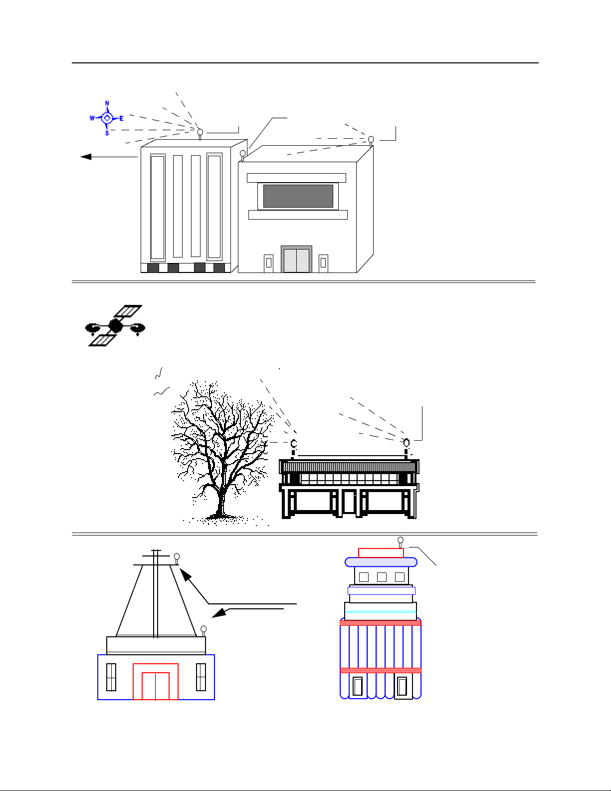
2.1.2 Antenna Mounting
It is important that the ThunderBolt’s antenna has the fullest possible view of the sky.
Getting the maximum number of satellites in view will reduce selective availability (SA)
the most and get the best timing performance from the ThunderBolt.
Typic ally, an t enna s ar e mo unte d pe rman entl y on a h igh poin t su c h as a r oof. Avoi d
overhanging objects such as trees and towers. Also take care to place the antenna away
from low lying objects such as neighboring buildings that may block a portion of the sky
near the horizon. If a full view of the sky is not possible, mount the antenna aiming
towards the Equator to maximize the southern view of the sky (choose a northern view in
the Southern Hemisphere) as shown in Figure 2-1. As a temporary solution the antenna
can even be placed in a southern facing window. Under these circumstances the
ThunderBolt will not have optimal timing performance.
Mounting standoffs for the Bullet II HE antenna are commonly found at marine stores.
Alternatively, your antenna can be mounted on a 3/4” pipe with 14 threads per inch.
Thunderbolt GPS Disciplined Clock 2-5
Page 28
Getting Started
Figure 2-1 Mounting the Bullet Antenna
To wa rd s
Equator
Preferred
Position
Obstructed
position
Improved
visibility
Better
Position
Radio Tower
Poor position
Better position
Avo id placing ant e n na
near interference
Obstructed
position
Place your antenna
as high as possible
to avoid obstructions
and interference
2-6 Thunderbolt GPS Disciplined Clock
Page 29
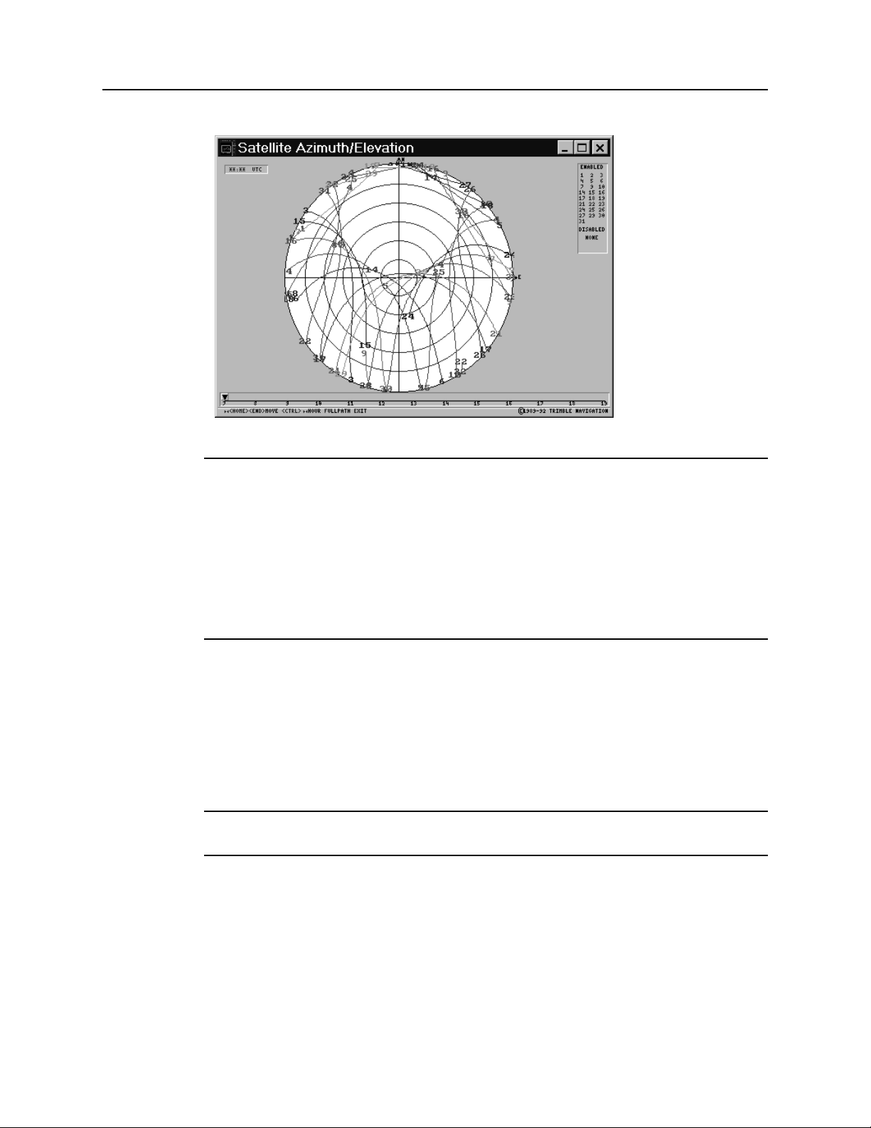
Figure 2-2 Satellite Density
Getting Started
*
Note – GPS satellites orbit from 60° North to 60° South. Although the GPS signal covers
the entire earth, satellite density is greater when facing the Equator than the Poles, as
illustrated on the sky plot in Figure 2-2. The curves in this figure represent the GPS
satellites’ path over a 24 hour period. To orient yourself with the diagram imagine lying on
your back facing the sky with your head pointing north. The circle represents the full view
of the sky from horizon to horizon. The ’hole’ in the north part of the sky represents an
area where there are no GPS satellites. The higher the latitude the closer the ’hole’ moves
toward the center of the sky. This graph represents the latitude of Hamburg, Germany. To
obtain a plot for your location, go to the Trimble web site at www.trimble.com and search
for SatNav. Follow the directions to get your data.
2.1.3 Antenna Cable
Both ThunderBolt and the Bullet II HE antenna have female “F” connectors. The 75 foot
cable that comes with the starter kit must be cut to a useful length and terminated. See
“Secure the EZF Connector to the Cable” on page 10 on terminating the cable. When
installing avoid bending the cable sharply.
F
Tip – Trimble recommends RG-59 cable. The maximum practical cable run is just over
100 feet. See Chapter 3 for more information.
2.1.4 Terminating the Antenna with the EZF Connector Kit
Yo ur s tar te r k it c om e s wi th 7 5 fe e t of c ab le . Th is c an b e cu t to a ny l en gt h an d te rm in at ed
using the EZF connector kit. When sizing the length of the cable be sure to include enough
slack for a drip loop and for normal movements of the antenna. When you cut your cable,
Thunderbolt GPS Disciplined Clock 2-7
Page 30

Getting Started
use the EZF Connector Kit to crimp a male “F” connector to the cut end. Be sure that all
contact surfaces are clean and firm before crimping.
Preparing Antenna Cable and Connectors
Instructions for preparing the antenna cable and connector are summarized below and
described on the following pages. Follow these guidelines and instructions to ensure a
successful installation.
• Mount the antenna
• Route the antenna cable
• Cut the cable to the desired length, allowing for a service loop
• Prepare the unterminated end of the cable for the EZF connector (See “Preparing
Cable for Termination” on page 8)
• Attach the EZF connector (See “Attach the EZF Connector” on page 9)
• Secure the EZF connector to the cable (See “Secure the EZF Connector to the
Cable” on page 10)
• Attach the cable to the ThunderBolt
2.1.5 Preparing Cable for Termination
Exposing the Center Conductor
Coaxial cable consists of a center conductor, a dielectric layer, a shield (that is, foil and
wire wrapped around the dielectric), and a weather-resistant cable jacket. The center
conductor supplies 5-volt (45 mA maximum continuous) power to the pre-amp in the
antenna and carries the GPS signal back to the receiver for processing. The first step in
preparing the cable is to expose the center conductor.
a. Using an exacto-knife or razor blade, cut a square 5/16” section off the end of
the cable to expose the center conductor. This will require that you cut
through the cable jacket, the braid, and the dielectric (see Figure 2-3).
Figure 2-3 Expose the Center Conductor
5/16"
8.0 mm
b. Clean the center conductor to ensure that the exposed rim is smooth. If
necessary, remove any residual dielectric or long braid strands that remain
wrapped around the center conductor.
2-8 Thunderbolt GPS Disciplined Clock
Page 31

c. Using an exacto-knife or razor blade, cut the cable jacket back another 1/8”,
leaving the dielectric and the shield intact. Be careful not to cut through these
sections of the cable.
Figure 2-4 Cutting the Cable Jacket
5/16"
1/8"
3.2 mm
8.0 mm
d. Fold the wire braid back over the cable jacket to expose the dielectric. Do not
cut the wire braid, it must be folded back. Be careful not to tear the foil around
the center dielectric.
Figure 2-5 Fold Back the Shield
Getting Started
The cable is now prepared for the connector. Follow the instructions below to attach the
EZF connector.
Attach the EZF Connector
The EZF cable connector assembly is contained in a cassette designed to simplify the
connector attachment. Four connectors are provided in this cassette. Only one connector is
required to terminate the cable.
a. Insert the cable into the connector closest to the edge of the cassette. Make
sure that the cable is centered.
Figure 2-6 Attaching the EZF Connector
Thunderbolt GPS Disciplined Clock 2-9
Page 32

Getting Started
b. Twist the cable back and forth as you push it firmly into the connector.
Continue pushing the cable into the connector until the cable dielectric is even
with the end of the connector mandrel.
c. Slide the connector out of the cassette. The dielectric should be flush with the
end of the mandrel. If not, place the cable connector assembly back into the
cassette repeat step 2 above. You may need to push the cable a bit harder
while twisting.
Secure the EZF Connector to the Cable
After installing the EZF cable connector, use the dummy port to secure the connector to
the cable.
a. Screw the dummy port onto the connector, being careful not to bend the wire
conductor.
b. Using two 7/16” wrenches, thread the dummy port into the EZF connector
and apply torque. This process will fit the EZF connector onto the cable.
Figure 2-7 Attaching the EZF Connector
1/8”
*
2-10 Thunderbolt GPS Disciplined Clock
Note – The connection will tighten gradually, however the amount of torque will increase
dramatically just before the cable connection is completely engaged. At this point, apply
another half turn to secure the connection.
c. Remove the dummy port from the EZF connector. The center conductor of the
cable should protrude about 1/8” from the connector housing. The white
dielectric should be flush with the inside of the connector.
Page 33

2.1.6 Power
Apply 24V DC to the Mate-n-Loc connector and cable. Red is positive; black is return.
The center connector (ground) is not necessary as all components are grounded to the
case. The case uses a conductive allodyne coating to insure a strong ground.
For more detailed information on the Mate-n-Loc connector, see of Chapter 3 (Hardware
Integration).
Getting Started
*
Note – After power is applied, ThunderBolt will take fifteen to twenty minutes for the
ovenized oscillator to warm up before it begins acquiring satellites. Once ThunderBolt
acquires satellites it begins a self-survey mode that allows the receiver to average out
selective availability. The complete process can take an hour.
2.1.7 Computer Connection
The ThunderBolt uses a standard RS-232 interface that can be connected directly to a PC.
Default Serial Port Configuration
The TSIP serial port is set at:
• 9600 baud
• No Parity
• 8-bit
• 1 stop/start bit
2.2 Software Interface
2.2.1 ThunderBolt Monitor Program
The easiest way to familiarize yourself with the features of the ThunderBolt is by using the
ThunderBolt Monitor Program. Simply copy the program onto the hard drive of a PC
running Windows 95 or later.
Reference Fig. 2-8
Thunderbolt GPS Disciplined Clock 2-11
Page 34

Getting Started
Figure 2-8 ThunderBolt Monitor Program
2.2.2 TSIPCHAT
The TSIPCHAT program is a DOS-based application designed to help the programmer in
the development environment. The program reads TSIP report packets and prints them to
the screen. It allows the user to exercise TSIP commands by translating the keystroke
codes into commands which are output over the serial port.
TSIPCHAT Interface
The following Command Packets allow you to change ThunderBolt configuration and
operation settings.
To st art the p rogr am, type TSI PCH AT - cl f or C OM1 or T S IPC HAT -c2 for COM 2. You
can change your choice while TSIPCHAT is running by using the [CTRL] +[I] command.
As TSIPCHAT starts, it displays a command list in the upper half of the console screen
(command window) and a running account of automatic (unrequested) reports in the
bottom half of the screen (auto window). It also sets the serial port to the default settings
of 9600 baud, 8-none-1.
If the receiver is alive and outputting time, Timing reports scroll immediately in the auto
window. If the auto window is empty, type ’v’ to test if the receiver responds within a
second with the receiver software version numbers; otherwise, “waiting for reply” remains
on the screen.
When issuing the TSIP command packet, use the [Space Bar] to scroll through the options.
Use the [Return] key to set them.
2-12 Thunderbolt GPS Disciplined Clock
Page 35

Receiver COM Port Settings
Packet BC sets the ThunderBolt GPS port characteristics. To change these settings, use the
TSIPCHAT program. [CTRL] + [Q] to change the receiver port. Use this command to set/
request the Input/Output baud rate, data bits, parity, stop bits, and flow control parameters.
2.2.3 TSIP
TSIP (commonly pronounced tee-sip), Trimble’s Standard Interface Protocol, consists of
command packets and report packets. The Basic Features section describes some of the
more commonly used commands and reports. A full description of TSIP can be found in
Appendix A.
2.3 Basic Features
The following features are of general interest to the timing user. For a complete list of
commands and reports see Appendix A.
Getting Started
*
Note – The packet number is not necessary if using the Windows Control Program.
2.3.1 Cable Delay Compensation
Packet 8E-4A allows the user to delay or advance the 1PPS. This may be desired to
compensate for a long cable run. Negative values advance the 1PPS, used to compensate
for cable delay. The 10MHz and 1PPS will remain synchronized.
2.3.2 Timing Information
Packets 8F-AB (Primary Timing Information) and Packet 8F-AC (Supplemental Timing
Information) contain most of the information that the user needs to monitor the operation
of the ThunderBolt. In the default configuration, these packets are broadcast once per
second.
2.3.3 Elevation Mask
This is the minimum elevation angle for satellites to be used in a solution output by the
receiver. See command BB in Appendix A. Satellites which are near the horizon are
typically more difficult to track due to signal attenuation, and are also generally less
accurate due to higher variability in the ionospheric and tropospheric corruption of the
signal. When there are no obstructions, the receiver can generally track a satellite down to
near the horizon. However, when this mask is set too low, the receiver may experience
frequent constellation switching due to low elevation satellites being obscured.
Thunderbolt GPS Disciplined Clock 2-13
Page 36

Getting Started
Frequent constellation switching is associated with undesirable timing jumps. Too high a
mask setting may reject good satellites. The current mask is set to five degrees and
provides a reasonable trade-off of the benefits and drawbacks. High accuracy users may
prefer a mask angle of around ten degrees, where the ionosphere and troposphere begin to
be more predictable.
2.3.4 Signal Level Mask
This mask defines the minimum signal strength for a satellite used in a solution. There is
some internal hysteresis on this threshold which allows brief excursions below the
threshold if lock is maintained and the signal was previously above the mask. The factory
default mask has been set to zero. High accuracy users may use a slightly higher mask of
6.0 to 8.0, since weaker measurements may be slightly noisier and are often caused by
reflected signals which provide erroneous ranges.
*
Note – A level of hysteresis in the signal level mask is allowed in the core operating
software. The hysteresis allows the receiver to continue using satellite signals which fall
slightly below the mask and prevents the receiver from incorporating a new signal until the
signal level slightly exceeds the mask. This feature minimizes constellation changes
caused by temporary fluctuations in signal levels.
2.3.5 Reference Position
Once the antenna is connected and power is applied, the GPS module generates a precise
PPS (pulse per second) signal, a 10 MHz frequency output, and several miscellaneous
periodic outputs. It calculates a clock-only solution from the GPS data. In clock-only
(position-hold) mode, a static reference position is established and all of the available
satellites are used to solve for a time solution. The reference position may be determined
automatically by the ThunderBolt (self-survey) or may be uploaded to the ThunderBolt by
the host, if the position is known. The accuracy and integrity of the timing solution is
highly dependent on the accuracy of the reference position.
If the host has not uploaded a reference position, the GPS module will automatically
conduct a position survey at power on. By default, the GPS module will average position
fixes for 2000 fixes before entering the clock-only mode. The survey period may be
adjusted by the host system using Packet 8E-A6. While the GPS module is performing its
survey, the accuracy of the timing outputs will be degraded.
Entering a Reference Position
The user may use Packet 31 (XYZ ECEF) or Packet 32 (Latitude, Longitude, Altitude) to
upload an accurate reference position. This reference position will be stored in EEPROM
and will be retained during power loss. With a reference position stored in EEPROM, the
GPS module bypasses the position survey procedure and enters clock-only mode. If the
antenna is moved, the user must send Packet 8E-45 to clear the position stored in
EEPROM. When the reference position is cleared, the GPS module will initiate a selfsurvey, unless the host uploads a new position using Packet 31 or Packet 32.
2-14 Thunderbolt GPS Disciplined Clock
Page 37

To st ore the refe r ence po sitio n fr om t he s elf- s urv ey p roce dure in t he E EPR OM, the host
must read the position contained in Packet 8F-AC and then upload the position using
Packet 8F-4C.
2.4 Maintenance
The ThunderBolt will provide years of maintenance free operation. Should the unit
experience a problem, you will be warned with an alarm. Contact Trimble for technical
direction and repair. There are no user-serviceable parts inside the ThunderBolt and
removing the cover will void the warranty.
Getting Started
Thunderbolt GPS Disciplined Clock 2-15
Page 38

Getting Started
This page is intentionally left blank
2-16 Thunderbolt GPS Disciplined Clock
Page 39

3Hardware Integration
General information on using a ThunderBolt for the first time is included in Chapter 2.
This chapter covers details of the hardware interface necessary for integration into a users
system.
3.1 ThunderBolt GPS Disciplined Clock
The ThunderBolt consists of two boards mounted inside an aluminum case. The board
pictured on the right contains the parts for power regulation and is mounted on the bottom
of the case. The second board contains the GPS Oscillator, and disciplining circuitry. This
board is mounted above the power board.
Figure 3-1 ThunderBolt Clock Components
Thunderbolt GPS Disciplined Clock 3-17
Page 40

Hardware Integration
Figure 3-2 ThunderBolt Clock Module
3.2 Interface Connector Pin-out Table
The RS-232C serial port uses a DB-9 connector. The pin-outs functions are shown
in Table 3-3, “Digital Data Connector Pinouts.” This configuration supports
connections to the RS-232 serial port on a computer.
Table 3-3 Digit al Da ta C onne ctor Pin outs
Pin Function Signal/Protocol
1Reserved
2TxDTransmit out/TTL
3RxDReceive in /TTL
4Not Used
5Ground
6Not Used
7Not Used
8Not Used
9Reserved
3.3 Antenna Cables
RG-59 cable is recommended due to its use in cable television networks. It is widely
available and inexpensive. Two RG-59 cables qualified for use with the Trimble GPS
3-18 Thunderbolt GPS Disciplined Clock
Page 41

Hardware Integration
modules are Belden, part number 82108 and Times Fiber, part number 32245. The RG-59
cable specifications are in Table 3-4, “RG-59 Cable Specifications.” Trimble recommends
that you select a cable meeting or exceeding these specifications.
*
Note – RG-59 is a 75 ohm coaxial cable. The ThunderBolt and Bullet II HE antenna are
compatible with 75 ohm cable. Compared to most 50 ohm cable, 75 ohm cable
provides superior transmissibility for the 1.5 GHz GPS signal and a better quality
cable for the price. Mismatched impedance is not a problem.
Table 3-4 RG-5 9 Ca b le S peci f icat ions
Type
Impedance
Capacitance
Vel of Propagation
Shielding
Connectors
Signal attenuation
RG-59
75 Ohm
16.5 pF/Foot (54.1 pF/meter)
84%
Foil and copper braid (100% coverage)
Waterproof F-type
<10dB for cable and connectors
RG-8 cable is lower loss than RG-59 and can be used when trying to maximize a cable run
without the use of inline amplifiers.
The following graphics compare RG-8 cable vs. RG-59 cable:
Thunderbolt GPS Disciplined Clock 3-19
Page 42

Hardware Integration
Figure 3-5 RG-59: Loss vs. Length
0
-5
-10
-15
-20
-25
Loss (db)
-30
Length (feet)
-35
0204080100120140160180200
Figure 3-6 RG-8: Loss vs. Length
Length (feet)
0
-5
-10
-15
-20
-25
Loss (db)
-30
-35
0204080100120140160180200
3-20 Thunderbolt GPS Disciplined Clock
Page 43

3.3.1 Routing/Securing Cable
After mounting the Bullet II HE antenna, route the cable from the antenna to the receiver.
Choose the most direct path to the receiver while avoiding the following hazards:
• Sharp Bends or Kinks in the Cable
• Hot Surfaces (Exhaust Manifolds or Stacks)
• Rotating or Reciprocating Equipment
• Sharp or Abrasive Surfaces
• Door and Window Jambs
• Corrosive Fluids or Gases
Yo u sh ou l d se cu re t he c ab le u s in g ti e -w ra ps . Wh en s ec ur i ng t he c ab le , s ta rt a t th e a nt en na
and work towards the receiver. Provide strain relief for the antenna cable connections by
ensuring that the cable is secured at points close to the antenna and the receiver.
Additional protection (for example, heat-shrink tubing) may be required to protect the
cable jacket at points where the opening is rough or sharp, such as where it enters or exits
bulkheads.
Hardware Integration
*
Note – Provide a service loop in the cable near the antenna to allow for disconnection of
the antenna and to allow moisture to drip away from the connections.
Once the cable is secured, the receiver end of the cable can be cut (if applicable) to an
appropriate length. Leave enough slack to allow for easy connection to the receiver and to
account for normal movement of the receiver (for example, gimbal or swivel mounts). The
final step, if applicable, is the installation of the connector on the receiver end of the cable.
3.4 Power Supply and Connector
The ThunderBolt comes with a 24V power supply. Power consumption is 15 watts cold
and 10 watts steady state. The connector is an AMP mate-n-loc (AMP part number
643228-1). The AMP mate-n-loc mating connectors are listed in the table below. An AMP
hand tool (PN 90300-2) may be required to assemble this connector.
Table 3-6 Powe r Sup ply Matin g Co nnec tor ( AMP Part Num b ers)
Description
Connector plug 1-480700-0 1
24-18 AWG pre-tinned brass pins 350706-1 2
Strain relief (optional) 1-640720-0 2
AMP Part
Number
Quantity
Required
*
Thunderbolt GPS Disciplined Clock 3-21
Note – The ThunderBolt uses a case ground scheme so that only two contacts are used,
left and right. The center (ground) is left empty.
Page 44

Hardware Integration
For high volume installations it is possible to integrate the ThunderBolt at the board level
without the power supply. The Prime power is +12V, -12V, +5v, and ground. Contact your
Trimble sales representative for further information.
3.5 Bullet II HE Antenna Specifications
Table 3-7 Bul l et I I HE Anten na P art Numb ers
Model Part Number
Bullet II HE 25045-10
Table 3-8 Phys ical Char acter istic s
Dimensions
Bullet II enclosure
Antenna Weight
Connector
Mount
3.04" diameter x 2.94" height (77.3mm x 74.6 mm)
Tex tu re d, o ff -w hi te p la st ic
3.5 oz. (100 grams)
F-type
1"-14 thread or 3/4” pipe thread
Table 3-9 Env i ronm enta l Sp ecifi catio ns
Operating Temperature
Storage Temperature
Vibration
Shock
Humidity
Salt Fog
Waterproof
-40°C to +85°C
-55°C to +100°C
2
0.04g
/Hz 10 Hz to 500 Hz
2
0.03g
/Hz 500 Hz to 850 Hz
2
0.02g
/Hz 850 Hz to 1200 Hz
40g (11 m/sec Sawtooth)
95% R.H. non-condensing
Mil. Std. 202F, Method 101D Condition B
Submersion to 1 meter
3-22 Thunderbolt GPS Disciplined Clock
Page 45

4Software Interface
The Trimble Standard Interface Protocol TSIP is described completely in Appendix A.
This section includes information helpful to the developer understanding the structure of
the ThunderBolt firmware.
4.1 Firmware Configuration
The ThunderBolt maintains its configuration parameters in a non-volatile memory device
called an EEPROM (Electrically Erasable Programmable Read-Only Memory.) Related
configuration parameters are grouped together and stored in an area of EEPROM called a
“segment” (there are seven user configurable segments). Immediately after a reset, the
ThunderBolt reads the contents of these segments from the EEPROM and stores a
working copy in RAM. The ThunderBolt then configures itself based on the working copy
of the segments. The user can modify the contents of these working copies using the “Set”
command packets listed in Appendix A. Likewise, the working copies of the segments can
be read by issuing the “Request” command packet and waiting for the “Report” packet
response. When the user alters a parameter, the ThunderBolt reconfigures itself
accordingly, but the contents of the EEPROM are not changed automatically.
The ThunderBolt provides two command packets for controlling the contents of the
segments stored in EEPROM. Command packet 0x8E-4C allows the user to save the
contents of any or all working copies of the segments to EEPROM. Command packet
0x8E-45 allows the user to set the contents of any or all the segments stored in EEPROM
to the “Factory Default” setting listed in the table below.
The tables in Appendix A provide details on each of the seven user configurable segments.
4.2 Firmware Upgrades
When firmware upgrades are available Trimble will provide software and instructions at
that time.
4.3 Firmware Evolution
The first major revision of the firmware (revision 2.10) added some additional
functionality to the ThunderBolt. The 2.10 firmware includes:
Thunderbolt GPS Disciplined Clock 4-23
Page 46

Software Interface
• Kalman Filtering for better performance during holdover. (see Operations for
more information)
• 1 PPS Calibrated to the USNO Master Clock for a more accurate “out of box”
performance.
• New Position Integrity Monitor that warns the user if the receiver is using an
incorrect position.
• User Selectable Recovery Algorithm that allows the user to define how the clock
will recover from holdover.
• Quiet TSIP Options that allows the user to choose which packets, if any, are to be
reported.
• The loop time constant is reduced to 100 seconds (from 300 seconds). This gives
better unit to unit synchronization, while 300 seconds give better absolute
synchronization.
No functionality or obsolete TSIP packets were removed during this revision.
4.4 Windows Control Program
A Windows program is available that demonstrates the abilities of the ThunderBolt. The
program is highly intuitive, and is excellent as a familiarization tool, but is not intended
for development or implementation. The source code is not available.
4-24 Thunderbolt GPS Disciplined Clock
Page 47

5Operations
5.1 General GPS Description
Every GPS satellite transmits the Coarse/Acquisition (C/A) code and satellite data
modulated onto the L1 carrier frequency (1575.42 MHz). The C/A code is a unique
pseudo-random number for each satellite. The satellite data transmitted by each satellite
includes a satellite almanac for the entire GPS system, its own satellite ephemeris and its
own clock correction.
The satellite data is transmitted in 30-second frames. Each frame contains the clock
correction and ephemeris for that specific satellite, and two pages of the 50-page GPS
system almanac. The time required to transmit the complete system almanac is 12.5
minutes and the time to transmit the satellite ephemeris is 30 seconds.
The system almanac contains information about each of the satellites in the constellation,
ionosphere data, and special system messages. The ephemeris contains detailed orbital
information for a specific satellite. The GPS system almanac changes infrequently and is
typically valid for weeks. Ephemeris data changes hourly, but is valid for up to four hours.
The GPS control segment updates the system almanac weekly and the ephemeris hourly
through three ground-based control stations. During normal operation, the ThunderBolt
updates the ephemeris stored in its memory at 30 minute intervals.
The performance of a GPS receiver at power-on is determined largely by the availability
and accuracy of the satellite ephemeris data and the availability of a GPS system almanac.
5.1.1 Oscillator Disciplining Basics
We u se the te rm “discipline” to refer to the process of adjusting the frequency and phase of
the ThunderBolt timing outputs into alignment or synchronism with an external reference
source, namely GPS.
GPS receivers, like all radio receivers, require a local reference oscillator in order to detect
and decode the incoming RF (radio-frequency) signal. The ThunderBolt’s GPS receiver
electronics are designed to accept a 10 MHz reference oscillator frequency. The GPS
receiver electronics, in conjunction with the CPU and support circuitry, divides this 10
MHz reference down to a 1 PPS signal. Based on measurements taken with the GPS
receiver electronics and information transmitted by the satellites, the ThunderBolt is able
to determine the frequency offset of the 10 MHz reference and the phase offset of the 1
PPS output relative to GPS or UTC. By knowing this offset information, the ThunderBolt
can cause these timing outputs to move into sync with GPS or UTC by adjusting the
frequency of the 10 MHz clock and by shifting the 1 PPS output.
Thunderbolt GPS Disciplined Clock 5-25
Page 48

Operations
The frequency of the 10 MHz clock is adjusted with the help of a Digital-to-Analog
Converter (DAC.) The CPU’s firmware determines how much to adjust the frequency
based on GPS measurements and information. The DAC gets a number from the CPU and
converts it into an analog voltage which is fed to the control voltage input of the 10 MHz
oscillator. Variations in the control voltage produce corresponding changes in the
frequency of the oscillator. Changing the frequency of the oscillator also causes the 1 PPS
offset to change. The ThunderBolt corrects for small errors in PPS offset by adjusting the
frequency of the oscillator only and not by shifting the PPS. This process is called “phase
locking”. The ThunderBolt spends most of its time in this phase locking mode.
When the ThunderBolt first begins to synchronize to UTC/GPS, there will be a large PPS
offset. In order to correct for this offset quickly, the ThunderBolt will shift the PPS output
into alignment. The resolution of this shift is 100 ns and is due to a 10 MHz clock that
drives the PPS shifting circuitry. What this 100 ns resolution means is that the PPS shifting
mechanism can align the PPS to UTC/GPS only to within +/- 50 ns, but it can do it
instantly. The rest of the PPS correction must be achieved with the phase locking
technique described above and is a gradual process.
At any given time, the ThunderBolt disciplining mechanism can be described as being in
one of several states. The mechanism transitions from one state to the next in response to
the conditions described below.
From reset, the ThunderBolt disciplining mechanism enters the Power-Up state. In this
state, the oscillator is allowed to warm up to an adequately stable state. At this point the
GPS receiver electronics are beginning to track satellites, and time or position fixes
become available. The initial synchronization process begins by adjusting the frequency
of the oscillator based on the frequency offset information only. At the same time, the PPS
output is constantly shifted into place. Once the frequency is close, the unit shifts into one
of its phase-locking modes and the timing outputs begin to settle in. After a period of
settling, the ThunderBolt transitions to the Normal state.
Figure 5-1ThunderBolt Disciplining State Diagram
Reset
Power-Up
Normal
(Fast)
Recovery
Holdover
In the Normal state, the ThunderBolt maintains the synchronization of the timing outputs
using phase-locking. As long as valid GPS signals and measurements are received, the
ThunderBolt is as happy as can be. Any disruption in the GPS receiver (e.g. loss of GPS
5-26 Thunderbolt GPS Disciplined Clock
Page 49

Operations
signal) will cause the ThunderBolt to transition into the Holdover state. The user can
instruct the ThunderBolt to transition to the Recovery state with command packet 0x8EA3.
In the Holdover state, the ThunderBolt relies, to a high degree, on the stability of the 10
MHz oscillator to maintain the integrity of the timing outputs since they cannot be
disciplined to GPS in this state. However, while the ThunderBolt is in the Normal state, it
attempts to learn as much about the stability characteristics of the oscillator as possible. If
the ThunderBolt has spent sufficient time in the Normal state (e.g. 24 hours) then some of
the instability of the oscillator can be removed during Holdover based on what the
ThunderBolt has learned about the oscillator. When valid GPS signals return, the
ThunderBolt will transition to the Recovery state.
In the Recovery state, the ThunderBolt removes any PPS phase or 10 MHz frequency
offset from UTC/GPS that was accumulated during Holdover. This is accomplished by
either quickly shifting the PPS into alignment (jam sync) or by more slowly shifting the
frequency of the 10 MHz oscillator by a specified amount until the PPS has slewed back
into alignment or by using both methods. The user can control the Recovery process with
parameters set with packet 0x8E-A8. If a fast recovery is desired, then the users should
allow jam syncs (PPS shifting) to be used. If it is important to maintain 10 million clock
cycles per PPS pulse then disable jam syncs and set the maximum 10 MHz frequency
offset to a tolerable value.
Two h oldo ver s tat es ar e de fin e d: A uto H old over and Man ual Hold over. Bo th s tate s
function as described above. The Auto Holdover state is entered automatically whenever
the ThunderBolt detects a loss of valid GPS signals. The Manual Holdover state is entered
in response to a user command (packet 8E-A3) and is intended to be used for testing
purposes. The ThunderBolt will transition out of Auto Holdover mode on its own, but the
user must command the unit to leave Manual Holdover. If the ThunderBolt is not
receiving valid GPS signals when instructed to leave Manual Holdover, then it will enter
the Auto Holdover state.
One final state is defined, but not shown on the state diagram. The Disabled state is
entered (and left) in response to a user command (packet 8E-A3.) In the Disabled state,
timing output control by the ThunderBolt routines is completely halted. This is different
from the Holdover states which allow the ThunderBolt to continue to control the timing
outputs based on learned behavior. The Disabled state allows the user to set the oscillator
frequency control voltage directly using command packet 8E-A0. No other state allows
the user to set the control voltage. This state is used by the factory to perform production
tests, but may be useful to users for testing.
5.1.2 Kalman Filtering
Kalman filtering is a technique that improves the performance of a GPS
disciplined clock when GPS drops out. This state is called holdover. During
holdover the clock relies solely on the oscillator. Oscillator performance is subject
to two basic effects. First, changes in environmental temperature can cause the
oscillator to speed up to slow down. Second, the oscillator has a natural tendency
to drift over time. This is called aging. Both temperature and aging can be
mathematically predicted. However, the characteristics vary from crystal to
Thunderbolt GPS Disciplined Clock 5-27
Page 50

Operations
crystal. The Kalman filtering monitors the unique oscillator performance over time
and temperature and records this behavior. Then when the clock goes into holdover
this filtering corrects for these effects producing a more accurate clock. The longer
a clock has to ’train’ the better the Kalman filtering performance will be. 24 hours
is considered the minimum necessary for good performance.
5.1.3 Timing Accuracy
Selective Availability
The U.S. Department of Defense (DoD), through the Selective Availability (S/A)
program, intentionally degrades GPS accuracy of civilian users. The S/A program creates
position errors by modifying the apparent position of each satellite and/or introducing
random dither into each satellites’ clock. Historically S/A has relied on the latter.
In extreme cases, all sources of error (natural, PDOP, and S/A) can combine to produce
large position errors. The DOD’s definition of accuracy under S/A is 100 meters (300
nanoseconds) 2D RMS (horizontal 2 dimensional, 95% of the time). In April 1996, the
U.S. government approved plans for disabling S/A.
5.1.4 Oscillator Performance
Oscillator performance is a key component of a GPS disciplined clock. Understanding
some basic characteristics of oscillators will help you understand ThunderBolt’s
performance under various circumstances.
Oscillators work by outputting a frequency. A perfect oscillator would have a frequency
that looked like a sine wave. Each cycle would be identical to every other cycle. However,
no oscillator is perfect and the output of a real oscillator looks like a series of imperfect
sine waves, each one varying slightly from the last. This variation is important because no
matter how slight, the variations add up. It adds up in a way that is not intuitively obvious.
Consider the performance of a real-life oscillator compared to some perfect measurement
of time. Plot fast performance above the X-axis and slow performance below the X-axis.
In a period of a few seconds the error of the quartz oscillator will appear as white noise.
The white noise error is evenly spaced above and below the X-axis at “0” representing
truth.
5-28 Thunderbolt GPS Disciplined Clock
Page 51

Figure 5-2 White Noise
Operations
White Noise
tim e (s a m p le s )
magnitude
1.5
0.5
-0.5
-1
-1.5
-2
2
1
0
20 40 60 80 100 120 140 160 180
As time passes, errors begin to add up and the oscillator starts to drift from truth. This drift
becomes more dramatic over longer periods. Mathematically the nature of the oscillator
performance changes. White noise has a statistical average or mean that is zero. Over
longer periods the oscillator’s mean is constantly changing. This creates a “random walk”
pattern.
Figure 5-3 Random Walk
5
4
3
2
1
0
magnitude
-1
-2
-3
-4
-5
20 40 60 80 100 120 140
Thunderbolt GPS Disciplined Clock 5-29
Random Walk
tim e (sam p les )
Page 52

Operations
Allan Variance
One way to look at oscillator performance is with a diagram called an Allan Variance. The
Allan Variance simply plots oscillator performance versus time. This diagram may look
confusing at first, but is really very simple.
Figure 5-4 Allan Variance
sigma (T)
10
10
10
10
10
-9
-10
-11
-12
-13
10
White Noise Region
Slope: -1
-1
10
Typical Allan Variance
Random Walk Region
Slope: +0.5
Flicker Floor
Slope: 0
0
10
1
10
2
10
3
4
10
T (seconds)
The downward slope represents the area of white noise. Lower is better. Notice that the
line decreases with time. An intuitive way to think about the Allan Variance is to think of
the distance from the X-axis to the line as the slope of a line that can be drawn through a
section of oscillator performance.
A short sample of oscillator performance allows room for a steep line to be drawn. A
longer sample restricts the slope. The shallower slope corresponds to better performance.
In the first few seconds the performance becomes better as the measurement time
increases. However, the variations start to add up and the performance starts to wander.
The magnitude of this wander increases until it approaches a random walk.
A random walk has no mean. It is a curious characteristic in nature. It is not unique to
oscillators. If you toss a coin and plot one square up for heads and one square down for
tails it will exhibit the same sort of behavior as an oscillator over time, white noise in the
short term, the flicker floor and eventually a random walk.
5-30 Thunderbolt GPS Disciplined Clock
Page 53

Operations
Other Conditions Affecting Oscillator Performance
Yo u wi ll f in d ot he r co n di ti ons t ha t af fe ct o sc il la to r p er fo rm an ce . Te m pe ra tu re w il l c ha ng e
the output of an oscillator. It is well known that oscillators are very sensitive to
temperature variations. One of the things that can be done to protect quartz from
temperature changes is to place the crystal inside a heated oven. Typically, an ovenized
oscillator will be heated up to 85°C while the ambient temperature changes between 0°C
to 70°C. Quartz performance will also change with age. However, the performance will
tend to become more consistent with age.
Allan Variance of GPS
GPS will remove variation due to temperature, age, and random walk from the oscillator
performance. The Allan Variance for GPS will be a straight line that constantly decreases.
The output of GPS is very precisely controlled by a series of atomic clocks and corrections
from ground stations. The variation is white noise, but it does not have a random walk or
flicker floor. The white noise is dominated by selective availability and will not be as
accurate as the oscillator.
Figure 5-5 Allan Variances with GPS
sigma (T)
10
10
10
10
10
-9
-10
-11
-12
-13
10
Typi cal Allan Vari ances
GPS
xtal
-1
10
0
10
1
10
2
10
3
4
10
T (seconds)
GPS + Oscillator
Thunderbolt GPS Disciplined Clock 5-31
Page 54

Operations
The key is to correct the oscillator with GPS just before the oscillator starts into random
walk.
5.2 Timing Between Sites
Many customers are interested in synchronizing between wireless base-stations and want
to know if two units viewing the same set of satellites will track more closely than two
units viewing independent sets of satellites. Data shows that unit to unit performance is on
the order of +
15 nanoseconds (three sigma). This does not include any static time offset
that may exist between two units. Static time offsets can be determined by comparing one
ThunderBolt under test to a known standard or gold unit.
5.3 GPS Timing
GPS disciplined clocks are used in many applications such as time/frequency standards,
site synchronization systems, wireless voice and data networks, and event measurement
systems. The steering algorithm combines the short-term stability of the oscillator with the
long-term stability of GPS. This added GPS discipline allows the use of ovenized quartz
oscillators which have poorer stability than atomic oscillators such as rubidium cells, but
which are much more reliable and cost-effective.
The GPS constellation consists of 24 orbiting satellites. Each GPS satellite contains a
highly stable atomic clock (cesium), which is continuously monitored and corrected by the
GPS control segment. Consequently, the GPS constellation can be considered a set of 24
orbiting clocks with world-wide 24-hour coverage.
GPS time accuracy is bounded by the same sources of error that limit position accuracy.
Please see Table 5-1 below.
Table 5-1 G PS E rror Sour ces
Error Source 1 Standard Deviation
Selective Availability 100 ns
Atmospheric Models (Ionosphere) 5 - 50 ns
Receiver noise (Multipath) 1 - 20 ns
Satellite Clock Model 10 ns
Satellite Orbit Model 5 ns
Antenna Survey 1 ns
The largest source of error is selective availability. The nature of S/A is white noise that
corrupts the GPS signal, but is kept within specific limits. This has the effect of making
GPS very accurate if measured over long time periods, but relatively poor if measured
over short time periods. This is almost opposite of the performance of a quartz oscillator.
Quartz provides a stable signal in the short term, but measured over minutes and hours the
crystal wanders dramatically. This behavior is called random walk. Please see “Oscillator
Performance” on page 28.
5-32 Thunderbolt GPS Disciplined Clock
Page 55

GPS disciplined clocks take advantage of these facts by gently steering the crystal
oscillators with a filtered GPS signal. The key is to allow the oscillator a free reign until it
starts into a random walk phase. At that point the GPS comes into play by increasing or
decreasing a steering voltage. This speeds up or slows down the oscillator, guiding it back
toward UTC or GPS time.
5.3.1 Timing Operation
ThunderBolt is designed and configured for static timing and synchronization
applications. Once power is applied, ThunderBolt automatically acquires GPS satellites,
computes position and time fixes, outputs a PPS and 10 MHz signal, and conducts a selfsurvey for 2000 fixes to establish an accurate reference position. With an accurate
reference position acquired, ThunderBolt automatically switches to over-determined clock
mode, activates its T-RAIM algorithm and outputs a precise PPS. The over-determined
clock solution mitigates the effects of S/A by using all available satellites to formulate a
timing solution that is more accurate than any single timing solution.
ThunderBolt's default configuration provides optimal timing accuracy without
intervention from the user. The one item the user or host controller may want to modify is
the delay introduced by the antenna cable. Cable delay can be significant (1.25
nanoseconds per foot). ThunderBolt is shipped from the factory with zero cable delay.
Testi ng at t he Un i ted S tate s Nav el Ob serv a tor y show s tha t the P P S is o n tim e com p are d to
UTC/GPS with no cable, e.g. a ThunderBolt with a bullet II HE antenna directly on the
connector would be on time. Any cable will delay the PPS. Adding a cable delay
correction (see packet 0x8E-4A) will shift both the 1PPS and the 10 MHz together. The
maximum recommended cable delay is an entry of 50 milliseconds.
Operations
UTC vs. GPS Time
Please note that GPS time differs from UTC (Universal Coordinated Time) by a variable,
integer number of seconds, as described below.
UTC = (GPS time) - (1 GPS to UTC offset)
As of January 1999, the GPS to UTC offset was 13 seconds. Historically, the offset
increases by one second approximately every 18 months. System designers should plan to
read the offset value as a part of the timing interface to obtain UTC. The GPS week
number is in reference to a base week (Week #0), starting January 6, 1980. The GPS and
UTC systems are based on the same second. However, UTC adds or subtracts leap
seconds to compensate for the slowing motion of the Earth. Since the systems run
independently, at any one time there may be as much as 1microseconds difference
between the systems. Historically the difference is less than 100 nanoseconds. The GPS
receiver automatically corrects for this difference. It is important to remember that any
real-time UTC is actually a prediction of UTC. The official UTC time is published
approximately one month after the fact. For more information on UTC, refer to the US
Naval Observatory or National Institute of Science and Technology (NIST) web pages
(see the Reference section).
Thunderbolt GPS Disciplined Clock 5-33
Page 56

Operations
Timing Pulse Output (PPS) and 10 MHz
Several options are available for the timing outputs. The PPS can be turned off and on, and
the polarity for both the PPS and 10 MHz can be set by the user.
Figure 5-6 PPS with rising edge
Timing Edge
Figure 5-7 PPS with falling edge
Timing Edge
5-34 Thunderbolt GPS Disciplined Clock
Page 57

Operations
Figure 5-8 10 MHz with positive zero crossing (shown with rising edge)
PPS
10 Mhz
Timing Edge
Figure 5-9 10 MHz with negative zero crossing (shown with rising edge)
PPS
Timing Edge
10 MHz
The PPS is generated from the 10 MHz and the rising edge will match the zero crossing
within 10 nanoseconds. When the PPS is adjusted using the cable delay command, the
phase of the 10 MHz will move by the same amount so that the rising edge of the PPS
always corresponds to the zero crossing of the 10 MHz.
Thunderbolt GPS Disciplined Clock 5-35
Page 58

Operations
5.3.2 System Architecture
Figure 5-10 ThunderBolt System Architecture
GPS Receiver
Electronics
10 MHz Clock
10 MHz OCXO
GPS Data
Control Voltage
CPU and Support
Circuitry
Digital to Analog
Converter
RS-232
Serial I/O
1 PPS Output
10 MHz Output
5-36 Thunderbolt GPS Disciplined Clock
Page 59

ATrimble Standard Interface
Protocol for ThunderBolt
The Trimble Standard Interface Protocol (TSIP) may be characterized as a set of data
packets used to transmit information to and receive information from a Trimble GPS
receiver. Trimble products commonly support a version of TSIP that is customized to the
attributes of the product; this appendix describes the ThunderBolt customization. Many
TSIP data packets are common to all products that use TSIP. An example would be a
single precision position output packet. Other packets are unique to a product. An example
of a unique ThunderBolt packet is a packet designed to allow the control and monitoring
of an oven oscillator. Custom packets are only used in the products for which they have
been created.
TSIP is a powerful and compact interface protocol that has been designed to allow the
system developer a great deal of flexibility in interfacing to a Trimble product. This
appendix has been generated and reviewed with care, however, history has shown that it is
surprisingly difficult to generate a TSIP appendix that is entirely free of errors. There is no
reason to believe that this appendix will be an exception. Trimble is always grateful to
receive reports of any errors in either products or documentation.
A.1 Interface Scope
The ThunderBolt GPS module has one configurable serial communication port, which is a
bi-directional control and data port utilizing the Trimble Standard Interface Protocol
(TSIP). The data I/O port characteristics and other parameters are user programmable
stored in non-volatile memory (EEPROM.)
The TSIP protocol is based on the transmission of packets of information between the user
equipment and the GPS receiver. Each packet includes an identification code that
identifies the meaning and format of the data that follows. Each packet begins and ends
with control characters. See section A8 for packet structure details.
The TBOLTCHT (ThunderBolt Chat) utility, part of the ThunderBolt Tool Kit, was
created to exercise a commonly used subset of the ThunderBolt TSIP packets. The
TBOLTCHT source code that is provided with the ThunderBolt starter kit is an excellent
guide for embedded software designers to use as a reference for developing ThunderBolt
interface code.
Thunderbolt GPS Disciplined Clock A-1
and
Page 60

Tr i m b l e S t a n d a r d I n t e r f a c e P r o t o c o l f o r T h u n d e r B o l t
A.2 Automatic Output Packets
In its default configuration, the ThunderBolt GPS disciplined clock sends packets 0x8FAB and 0x8F-AC once per second while operating in a time-only fix mode (e.g. OverDetermined Clock mode.) While operating in a position fix mode (e.g. while performing a
self-survey,) the ThunderBolt also sends packets 0x42 (XYZ position) and 0x43 (ECEF
velocity.) For most system implementations these output packets provide all of the
information required for operation including time, position, GPS status, and health. Table
A-1 lists all of the packets that can be configured for automatic output. The Masking
Packet ID column lists the command packet that controls the automatic output of these
packets. To reduce serial port traffic, the user can disable all of the automatic output
packets and then request packets only when needed.
Tab le A -1 Aut om ati c Out pu t Pa cke ts
Output
Packet ID
0x42 Position XYZ
0x43 Velocity XYZ,
0x4A Position LLA,
0x56 Velocity ENU,
0x58 Satellite system
0x5B Satellite
0x6D Satellite selection
0x83 Position XYZ
0x84 Position LLA,
0x8F-A7 Individual satellite
Description Masking
(ECEF), single
precision
single precision
single precision
single precision
data (almanac, utc
info, ephemeris,
ionosphere info, sv
health)
ephemeris status
list, DOPS, fix
mode
(ECEF), double
precision
double precision
solutions
Request
Packet ID
0x35 0x37 When a position fix is
0x35 0x37 When a position fix is
0x35 0x37 When a position fix is
0x35 0x37 When a position fix is
0x8E-A5 0x38 When new system data
0x8E-A5 0x3B When a new ephemeris
0x8E-A5 0x24 When the satellite
0x35 0x37 When a position fix is
0x35 0x37 When a position fix is
0x8E-A5 None Once per second
Packet ID
When Sent
computed
computed
computed
computed
is received
is received
selection list is updated
computed
computed
A-2 Thunderbolt GPS Disciplined Clock
Page 61

Tr i m b l e S t a n d a r d I n t e r f a c e P r o t o c o l f o r T h u n d e r B o l t
0x8F-AB Primary timing
packet
0x8F-AC Supplemental
timing packet
0x8E-A5 0x8E-AB Once per second
0x8E-A5 0x8E-AC Once per second
A.3 Customizing ThunderBolt Operations
The ThunderBolt provides a number of user configurable parameters that allow the user to
customize the operation of the ThunderBolt. These parameters are stored in a non-volatile
memory chip (EEPROM) to be retained during loss of power and through resets. At reset
or power-up, the ThunderBolt configures itself based on the parameters stored in the
EEPROM. The user can change the values of these parameters to achieve the desired
operations using a variety of TSIP packets. The ThunderBolt configures itself based on the
new parameter immediately, but the new parameter value is not automatically saved to the
EEPROM. The user must direct the ThunderBolt to save the parameters to the EEPROM.
Parameters are grouped into sections of the EEPROM called segments. Each segment is
identified with a number and contains a group of related parameters. To change the
parameter values stored in EEPROM, the user sends packet 0x8E-4C to direct the
ThunderBolt to save the current parameter values in a specified segment in the EEPROM.
The user can also direct the ThunderBolt to set the parameter values to their factory default
settings with packet 0x8E-45. When a segment is set to its factory defaults, the contents of
the EEPROM segment are set and the ThunderBolt configures itself with the default
settings.
In brief, to customize the ThunderBolt operations for your application:
• Configure the ThunderBolt using TSIP command packets until the desired
operation is achieved.
• Use TSIP packet 0x8E-4C to save the settings in non-volatile memory
(EEPROM.)
The new settings will control ThunderBolt operations whenever it is reset or power cycled.
The following tables list the user configurable parameters by segment number. Each table
lists the parameter name, its factory default value, and the TSIP packet that sets or reads
the parameter value (typically, one TSIP packet sets or reads several related parameters.)
Thunderbolt GPS Disciplined Clock A-3
Page 62

Tr i m b l e S t a n d a r d I n t e r f a c e P r o t o c o l f o r T h u n d e r B o l t
Tab le A -2 Re ce iv er Co nfi gu rat io n - S eg men t 3
Parameter Factory Default Set Request Report
receiver mode 4 (Full Position 3D)
dynamics code 1 (land)
elevation mask 0.175 radians (10 deg)
signal level mask 4 (amu) 0xBB 0xBB 0xBB
PDOP mask 8
PDOP switch 6
foliage mode 1 (sometimes)
Tab le A -3 Pack et I/ O C on trol - Se gm ent 4
Parameter Factory Default Set Request Report
Packet broadcast mask
mask 0
mask 1
Packet 0x35 data
position (byte 0)
velocity (byte 1)
timing (byte 2)
auxiliary (byte 3)
Datum 0 (WGS-84) 0x8E-15 0x8E-15 0x8F-15
0x05
0x00
0x01
0x01
0x00
0x00
0x8E-A5 0x8E-A5 0x8E-A5
0x35 0x35 0x35
Tab le A -4 Se ri al Po rt C on fig ur at ion - Se gm ent 5
Parameter Factory Default Set Request Report
Input baud rate 7 (9600 baud)
Output baud
rate
Data bits 8
Parity 0 (none) 0xBC 0xBC 0xBC
Stop bits 1
Input protocol 2 (TSIP)
Output protocol 2 (TSIP)
A-4 Thunderbolt GPS Disciplined Clock
7 (9600 baud)
Page 63

Tr i m b l e S t a n d a r d I n t e r f a c e P r o t o c o l f o r T h u n d e r B o l t
Tab le A -5 Ti mi ng Ou tp uts - Se gme nt 6
Parameter Factory Default Set Request Report
PPS enable 1 (enabled)
PPS sense 1 (rising edge) 0x8E-4A 0x8E-4A 0X8F-4A
PPS offset 0.0 (seconds)
Bias Uncertainty
Threshold
10 MHz sense 1 (rising edge) 0x8E-A1 0x8E-A1 0x8F-A1
UTC/GPS timing 0 (GPS timing) 0x8E-A2 0x8E-A2 0x8F-A2
300.0 (meters) 0x8E-4A 0x8E-4A 0x8F-4A
Tab le A -6 Ac cu rat e Po s iti on - Se gme nt 7
Parameter Factory Default Set Request Report
Position No stored
position
0x31, 0x32 0x8E-AC 0x8F-AC
Tab le A -7 Se lf -S ur vey - Se gme nt 8
Parameter
Self-survey enable 1 (enabled)
Position save flag 0 ( don’t save) 0x8E-A9 0x8E-A9 0x8F-A9
Self-survey count 2000 (fixes)
Factor y Default Set Request Report
Tab le A -8 Os ci lla to r Dis ci pli ni ng - Seg me nt 9
Parameter Factory Default Set Request Report
Time constant 100 (seconds)
Loop damping 1.2
OCXO gain -5.0 (Hz/volt)
Min. control voltage -5.0 (volts)
Max. control voltage 5.0 (volts) 0x8E-A8 0x8E-A8 0x8F-A8
Initial DAC voltage 0.0 (volts)
Recovery mode jam
sync threshold
Recovery mode max
frequency offset
300.0 (ns)
50.0 (ppb)
Thunderbolt GPS Disciplined Clock A-5
Page 64

Tr i m b l e S t a n d a r d I n t e r f a c e P r o t o c o l f o r T h u n d e r B o l t
A.4 Packets Output at Power-Up
After completing its self-diagnostics, the ThunderBolt automatically outputs the following
packet.
Tab le A -9 Pack ets O utp ut a t Pow er -u p
Output Packet ID Description
0x45 software version info
A.5 Changes to ThunderBolt Firmware
This manual represents firmware shipped after February 1998. Units shipped before that
time may have an earlier version of the firmware. This section describes some of the
packets that are obsolete and their replacements.
Tab le A -1 0 Ob sol et e Pa cke ts
Packet ID Packet Description Replacement ID
0x22 Position fix mode select 0xBB
0x23 Set initial position (XYZ ECEF) 0x31
0x2A Set initial position (lat, long, alt) 0x32
0x3D Set port configuration 0xBC
0x41 Report GPS time 0x8F-AB
0x8F-0B Timing superpacket 0x8F-AB & 0x8F-AC
0x8F-20 Last fix and extra information Various
A-6 Thunderbolt GPS Disciplined Clock
Page 65

Tr i m b l e S t a n d a r d I n t e r f a c e P r o t o c o l f o r T h u n d e r B o l t
A.6 Report Packets: ThunderBolt to User
The table below summarizes the packets output by the ThunderBolt. The table includes the
output packet ID, a short description of each packet, and the associated input packet. In
some cases, the response packets depend on user-selected options.
Tab le A -1 1 R ep or t Pa cke ts
Output ID Packet Description Input ID
0x42 Single-precision XYZ position 0x37, auto
0x43 Velocity fix (XYZ ECEF) 0x37, auto
0x45 Software version information 0x1F, 0x1E, 0x25
0x47 Signal level for all satellites 0x27
0x49 Almanac health page 0x29
0x4A Single-precision LLA position 0x37, auto
0x55 I/O packet options 0x35
0x56 Velocity fix (ENU) 0x37, auto
0x57 Information about the last computed fix 0x37
0x58 GPS system data 0x38, auto
0x59 Satellite enable/disable & health flag 0x39
0x5A Raw measurement data 0x3A
0x5B Satellite ephemeris status 0x3B
0x5C Satellite tracking status 0x3C
0x5F-11 EEPROM segment status 0x3F-11
0x6D Satellite selection list 0x24, auto
0x70 Filter configuration 0x70
0x83 Double-precision XYZ position 0x37, auto
0x84 Double-precision LLA position 0x37, auto
0xBB GPS receiver configuration 0xBB
0xBC Serial port configuration 0xBC
0x8F-15 Datum values 0x8E-15
0x8F-41 Manufacturing parameters 0x8E-41
0x8F-42 Production parameters 0x8E-42
0x8F-45 Revert segment(s) to factory default values 0x8E-45
0x8F-4A PPS characteristics 0x8E-4A
0x8F-4C Save segment(s) to EEPROM 0x8E-4C
0x8F-A0 DAC value 0x8E-A0
0x8F-A1 10 MHz sense 0x8E-A1
0x8F-A2 UTC/GPS timing 0x8E-A2
0x8F-A3 Disciplining command 0x8E-A3
Thunderbolt GPS Disciplined Clock A-7
Page 66

Tr i m b l e S t a n d a r d I n t e r f a c e P r o t o c o l f o r T h u n d e r B o l t
0x8F-A4 Test modes 0x8E-A4
0x8F-A5 Packet broadcast mask 0x8E-A5
0x8F-A6 Self-survey command 0x8E-A6
0x8F-A7 Individual satellite solutions Auto
0x8F-A8 Disciplining parameters 0x8E-A8
0x8F-A9 Self-survey parameters 0x8E-A9
0x8F-AB Primary timing packet 0x8E-AB, auto
0x8F-AC Secondary timing packet 0x8E-AC, auto
A.7 Command Packets: User to ThunderBolt
The table below summarizes the packets that can be input by the user. The table includes
the input packet ID, a short description of each packet, and the associated output packet.
Tab le A -1 2 C om man d Pa ck et s
Input ID Packet Description Output ID
0x1E Initiate cold reset or factory reset 0x45
0x1F Request software version information 0x45
0x24 Request GPS satellite selection list 0x6D
0x25 Initiate warm reset & self-test 0x45
0x27 Request signal levels 0x47
0x29 Request almanac health page 0x49
0x31 Set accurate initial position (XYZ ECEF) --
0x32 Set accurate initial position (lat, long, Alt) --
0x34 Set satellite selection for one-satellite mode --
0x35 Set/Request I/O options 0x55
0x37 Request status and values of last position and
velocity
0x38 Request satellite system data 0x58
0x39 Set/Request satellite disable or ignore health 0x59
0x3A Request last raw measurement 0x5A
0x3B Request current status of SV ephemeris data 0x5B
0x3C Request current satellite tracking status 0x5C
0x3F-11 Request EEPROM segment status 0x5F-11
0x70 Set/Request position filter enable/disable 0x70
0xBB Set/Request GPS receiver configuration 0xBB
0xBC Set/Request serial port configuration 0xBB
0x8E-15 Set/Request current datum 0x8F-15
0x8E-41 Request manufacturing parameters 0x8F-41
0x57 (and other
enabled packets)
A-8 Thunderbolt GPS Disciplined Clock
Page 67

Tr i m b l e S t a n d a r d I n t e r f a c e P r o t o c o l f o r T h u n d e r B o l t
0x8E-42 Request production parameters 0x8F-42
0x8E-45 Revert to default settings 0x8F-45
0x8E-4A Set/Request PPS characteristics 0x8F-4A
0x8E-4C Save segments to EEPROM 0x8F-4C
0x8E-A0 Set/Request DAC values 0x8F-A0
0x8E-A1 Set/Request 10 MHz sense 0x8F-A1
0x8E-A2 Set/Request UTC/GPS timing mode 0x8F-A2
0x8E-A3 Issue Disciplining Command 0x8F-A3
0x8E-A4 Setup a test mode 0x8F-A4
0x8E-A5 Set/Request packet broadcast mask 0x8F-A5
0x8E-A6 Issue self-survey command 0x8F-A6
0x8E-A8 Set/Request disciplining parameters 0x8F-A8
0x8E-A9 Set/Request self-survey parameters 0x8F-A9
0x8E-AB Request primary timing packet 0x8F-AB
0x8E-AC Request supplemental timing packet 0x8F-AC
A.8 Packet Structure
TSIP packet structure is the same for both commands and reports. The packet format is:
<DLE> <id> <data string bytes> <DLE> <ETX>
Where:
<DLE>
•
• <ETX>
• <
<DLE>
The bytes in the data string can have any value. To prevent confusion with the frame
sequences <DLE> <id> and <DLE> <ETX>, every <DLE> byte in the data string is
preceded by an extra <DLE> byte ('stuffing'). These extra <DLE> bytes must be added
('stuffed') before sending a packet and removed after receiving the packet. Notice that a
simple <DLE> <ETX> sequence does not necessarily signify the end of the packet, as
these can be bytes in the middle of a data string. The end of a packet is <ETX> preceded
by an odd number of <DLE> bytes.
Multiple-byte numbers (integer, float, and double) follow the ANSI / IEEE Std. 754 IEEE
Standard for binary Floating-Point Arithmetic. They are sent most-significant byte first.
Note that switching the byte order will be required in Intel-based machines. The data
types used in the ThunderBolt TSIP are defined below.
is the byte 0x10
is the byte 0x03
ID
> is a packet identifier byte, which can have any value excepting
.
<ETX>
and
• UINT8 - An 8 bit unsigned integer (0 to 255).
• SINT8 - An 8 bit signed integer (-128 to 127).
• INT16 - A 16 bit unsigned integer (0 to 65,535).
Thunderbolt GPS Disciplined Clock A-9
Page 68

Tr i m b l e S t a n d a r d I n t e r f a c e P r o t o c o l f o r T h u n d e r B o l t
• SINT16 - A 16 bit signed integer (-32,768 to 32,767).
• UINT32 - A 32 bit unsigned integer (0 to 4,294,967,295)
• SINT32 - A 32 bit signed integer (-2,147,483,648 to 2,147,483,647).
• Single — Float (4 bytes) (3.4x10-38 to 1.7x1038) (24 bit precision)
• Double —Float (8 bytes) (1.7x10-308 to 3.4x10308) (53 bit precision)
*
Note – Default serial port settings are: 9600, 8-none-1
A.9 Packet Descriptions
A.9.1 Command Packet 0x1E Initiate Cold or Factory Reset
This packet commands the ThunderBolt to perform either a cold reset or a factory reset. A
cold reset will clear the GPS data (almanac, ephemeris, etc.) stored in RAM and is
equivalent to a power cycle. A factory reset will additionally restore the factory defaults of
all configuration parameters stored in non-volatile memory (EEPROM.) This packet
contains one data byte equal to the ASCII letter ’K’ or ’F’. The data format is shown
below.
Tab le A -1 3 Co mma nd Pack et 0x 1E Da ta Fo rma t
Byte Item Ty p e Value Meaning
0ResetUINT8’K’ (0x4B)
’F’ (0x46)
cold reset
factory reset
I
Caution – The factory reset command will delete the stored position and will cause self-
survey to restart.
A.9.2 Command Packet 0x1F Request Software Version
This packet requests information about the version of software in the ThunderBolt. This
packet contains no data. The GPS receiver returns packet
0x45.
A.9.3 Command Packet 0x20 Request Almanac
This packet requests almanac data for one satellite. The packet contains one data byte
specifying the PRN number of the selected satellite. The GPS receiver returns packet
0x40.
A-10 Thunderbolt GPS Disciplined Clock
Page 69

Tr i m b l e S t a n d a r d I n t e r f a c e P r o t o c o l f o r T h u n d e r B o l t
A.9.4 Command Packet 0x24 Request GPS Satellite Selection List
This packet requests a list of satellites used for the current position/time fix. This packet
contains no data. The GPS receiver returns packet 0x
6D.
A.9.5 Command Packet 0x25 Initiate Warm Reset & Self Test
This packet commands the GPS receiver to perform a warm reset. This is not equivalent to
cycling the power because the ThunderBolt retains the GPS data (almanac, ephemeris,
etc.) it has collected and stored in RAM. The GPS receiver performs a self-test as part of
the reset operation. This packet contains no data. Following completion of the reset, the
receiver will output the start-up messages (see Table A-4.)
A.9.6 Command Packet 0x27 - Request Signal Levels
This packet requests signal levels for all satellites currently being tracked. This packet
contain no data. The GPS receiver returns packet 0x47 hex.
A.9.7 Command Packet 0x29 - Request Almanac Health Page
This packet requests the GPS receiver to send the health page from the almanac. This
packet contains no data. The GPS receiver returns packet 0x49.
A.9.8 Command Packet 0x31 Set Accurate Initial Position (XYZ Cartesian
ECEF)
This packet provides an accurate initial position to the GPS receiver in XYZ coordinates.
The GPS receiver uses this position for performing time-only fixes. If a survey is in
progress when this command is sent, the survey is aborted, the packet position data is used
immediately, and the ThunderBolt switches to Over-Determined Clock Mode.
Tab le A -1 4 C om man d Pa ck et 0 x3 1 D ata F or mat < <se gm ent 7 >>
Byte Item Type Units
0-3 X-axis Single Meters
4-7 Y-axis Single Meters
8-11 Z-axis Single Meters
Thunderbolt GPS Disciplined Clock A-11
Page 70

Tr i m b l e S t a n d a r d I n t e r f a c e P r o t o c o l f o r T h u n d e r B o l t
A.9.9 Command Packet 0x32 Set Accurate Initial Position (Latitude,
Longitude, Altitude)
This packet provides an accurate initial position to the GPS receiver in latitude, longitude,
and altitude coordinates. The GPS receiver uses this position for performing time-only
fixes. If a survey is in progress when this command is issued, the survey is aborted, the
packet position data is used immediately, and the ThunderBolt switches to OverDetermined Clock Mode. The coordinates entered must be in the current datum. See
packet 8E-15 for setting the datum or use the default WGS-84 datum.
Tab le A -1 5 C om man d Pa ck et 0 x3 2 D ata F or mat < <se gm ent 7 >>
Byte Item Type Units
0-3 Latitude Single Radians, north
4-7 Longitude Single Radians, east
8-11 Altitude Single Meters
A.9.10 Command Packet 0x34 – Set Satellite Selection For One-Satellite
Mode
This packet allows the user to control the choice of the satellite to be used for the onesatellite time-only fix mode. This packet contains one byte. If the byte value is 0, the GPS
receiver chooses the usable satellite with the highest elevation above the horizon. This
automatic selection of the highest satellite is the default action, and the GPS receiver does
this unless it receives this packet. If the byte value is from 1 to 32, the packet specifies the
PRN number of the satellite to be used.
A.9.11 Command Packet 0x35 Set or Request I/O Options
This packet requests the current I/O option states and allows the I/O option states to be set
as desired.
To r equ est th e opti on sta tes wi thou t chan ging th em , t he us er sen ds this pack e t with no dat a
bytes. To change any option states, the user includes 4 data bytes as shown in the table
below. The I/O options, their default states, and the byte values for all possible states are
shown below. These option states can be set into non-volatile memory (EEPROM) with
the
0x8E-4C command. The GPS receiver returns packet 0x55. See section A.3 for
information on saving the settings to non-volatile memory.
These abbreviations apply to the following table: ALT (Altitude), ECEF (Earth-centered,
Earth-fixed), XYZ (Cartesian coordinates), LLA (latitude, longitude, altitude), HAE
(height above ellipsoid), WGS-84 (Earth model (ellipsoid)), MSL geoid (mean sea level),
and UTC (universal coordinated time).
A-12 Thunderbolt GPS Disciplined Clock
Page 71

Tr i m b l e S t a n d a r d I n t e r f a c e P r o t o c o l f o r T h u n d e r B o l t
Tab le A -1 6 Co mma nd Pack et 0x 35 Da te Fo rm at << se gm ent 3 >>
Byte Data
Type
0Position01 01ECEF on
1Velocity01 01ECEF off
2Timing00 01GPS time reference
3Auxiliary00 01packet 5A off
Bit Default Va l u e Meaning Associate
ECEF off
10 01LLA off
LLA on
20 01HAE (datum)
MSL geoid
30 0 reserved
40 01single-precision position
double-precision position
5:7 0 reserved
ECEF on
10 01ENU off
ENU on
2:7 0 reserved
UTC time reference
packet 5A on
10 01raw PR’s in 5A
filtered PR’s in 5A
2Reserved
30 01output AMU
output dB/Hz
4:7 Reserved 0 0
d Packet
0x42 or
0x83
0x4A or
0x84
0x4A or
0x84
0x42/4A
0x83/84
0x43
0x56
0x42,
0x43,
0x4A,
0x83,
0x84,
0x56,
0x5A
0x5A
0x5A,
0x5C,
0x47
A.9.12 Command Packet 0x37 Request Status and Values of Last Position
This packet requests information regarding the last position fix (normally used when the
GPS receiver is not automatically outputting fixes). The GPS receiver returns the position/
velocity auto packets specified in the 0x35 message as well as message
contains no data.
Thunderbolt GPS Disciplined Clock A-13
0x57. This packet
Page 72

Tr i m b l e S t a n d a r d I n t e r f a c e P r o t o c o l f o r T h u n d e r B o l t
A.9.13 Command Packet 0x38 Request Satellite System Data
This packet requests current satellite data.The GPS receiver returns packet 0x58.
Tab le A -1 7 Co mma nd Pack et 0x 38 Da ta Fo rm at
Byte Item Type Va l u e Meaning
0OperationUINT81 must always be ’1’
1Type of dataUINT81
2
3
4
5
6
2Sat PRN#UINT80
1 - 32
Not used
Almanac
Health page, t
Ionosphere
UTC
Ephemeris
Data not satellite ID specific
satellite PRN number
, WNa
oa
A.9.14 Command Packet 0x39 Set or Request SV Disable and Health Use
Normally the GPS receiver selects only healthy satellites (based on transmitted values in
the ephemeris and almanac) which satisfy all mask values. This packet allows overriding
the internal logic and forces the receiver to either unconditionally disable a particular
satellite or to ignore a bad health flag. The GPS receiver returns packet
or 6 is requested; otherwise there is no reply.
0x59 if operation 3
*
It should be noted that when viewing the satellite disables list, the satellites are not
numbered but are in numerical order. The disabled satellites are signified by a “1” and
enabled satellites are signified by a “0”.
Tab le A -1 8 Co mma nd Pack et 0x 39 Da ta Fo rm at
Byte Item Type Va l u e Meaning
0OperationUINT81
2
3
4
5
6
1Satellite #UINT80
1 - 32
Note – At power-on and after a reset the default values are set for all satellites.
Enable satellite (default)
Disable satellite
Request enable/disable status
of all 32 satellites
Heed health (default)
Ignore health
Request heed - or - ignore
health on all 32 satellites
All 32 satellites
Any one satellite PRN number
A-14 Thunderbolt GPS Disciplined Clock
Page 73

Tr i m b l e S t a n d a r d I n t e r f a c e P r o t o c o l f o r T h u n d e r B o l t
I
Caution – Improperly ignoring health can cause the GPS receiver software to lock up, as
an unhealthy satellite may contain defective data. Use extreme caution in ignoring satellite
health.
A.9.15 Command Packet 0x3A Request Last Raw Measurement
This packet requests the most recent raw measurement data for one specified satellite. The
GPS receiver returns packet 0x5A if data is available.
Tab le A -1 9 Co mma nd Pack et 0x 3A Da ta Fo rma t
Byte Item Type Value Meaning
0Satellite numberINT80
1-32
all satellites in current tracking set
specific desired satellite
A.9.16 Command Packet 0x3B Request Current Status of Ephemeris Data
This packet requests the current status of satellite ephemeris data. The GPS receiver
returns packet 0x5B if data is available.
A.9.17 Command Packet 0x3C Request Current Satellite Tracking Status
The GPS receiver returns packet 0x5C if data is available.
Tab le A -2 0 Co mma nd Pack et 0x 3C Da ta Fo rma t
Byte Item Type Value Meaning
0satellite numberINT80
1-32
all satellites in current tracking
set specific desired satellites
A.9.18 Command Packet 0x3F-11 Request EEPROM Segment Status
Use command packet 0x3F-11 to requests the status of the EEPROM segments and to
clear the EEPROM status minor alarm bit (bit 10) in the supplemental timing packet 0x8FAC. The ThunderBolt replies with report packet 0x5F-11.
Thunderbolt GPS Disciplined Clock A-15
Page 74

Tr i m b l e S t a n d a r d I n t e r f a c e P r o t o c o l f o r T h u n d e r B o l t
A.9.19 Report Packet 0x42 Single-precision Position Fix
This packet provides current GPS position fix in XYZ ECEF coordinates. If the I/O
“position” option is set to "XYZ ECEF” and the I/O Precision-of-Position output” is set to
single-precision, then the GPS receiver sends this packet each time a fix is computed or in
response to packet 0x37. The data format is shown below.
Tab le A -2 1 R ep or t Pa cke t 0x4 2 Dat a Fo rma t
Byte Item Type Units
0-3 X Single meters
4-7 Y Single meters
8-11 Z Single meters
12-15 time-of-fix Single seconds
The time-of-fix is in GPS time or UTC as selected by the I/O “timing” option in packet
0x35. Packet 0x83 provides a double-precision version of this information.
A.9.20 Report Packet 0x43 Velocity Fix, XYZ ECEF
This packet provides current GPS velocity fix in XYZ ECEF (Earth-Centered EarthFixed) coordinates. If the I/O “velocity” option (packet 0x35) is set to “XYZ ECEF”, then
the GPS receiver sends this packet each time a fix is computed or in response to packet
0x37. The data format is shown below. The time-of-fix is in GPS time or UTC as selected
by the I/O “timing” option.
Tab le A -2 2 Re por t Pa ck et 0 x43 D ata F orm at
Byte Item Type Units
0-3 X velocity Single Meters/second
4-7 Y velocity Single Meters/second
8-11 Z velocity Single Meters/second
12-15 bias rate Single Meters/second
16-19 time-of-fix Single Seconds
A.9.21 Report Packet 0x45 Software Version Information
This packet provides information about the version of software in the ThunderBolt. The
GPS receiver sends this packet after power-on and resets and in response to packet
0x1F.
A-16 Thunderbolt GPS Disciplined Clock
Page 75

Tr i m b l e S t a n d a r d I n t e r f a c e P r o t o c o l f o r T h u n d e r B o l t
Tab le A -2 3 Re por t Pa ck et 0 x45 D ata F orm at
Byte Item Type
0Application layer major version numberUINT8
1Application layer minor version numberUINT8
2Month UINT8
3Day UINT8
4Year number minus 1900 UINT8
5GPS core layer major revision numberUINT8
6GPS core layer minor revision numberUINT8
7Month UINT8
8Day UINT8
9Year number minus 1900 UINT8
A.9.22 Report Packet 0x47 Signal Level for All Satellites Tracked
This packet provides received signal levels for all satellites currently being tracked or on
which tracking is being attempted (i.e., above the elevation mask and healthy according to
the almanac). The receiver sends this packet only in response to packet
format is shown below. Up to 8 satellite number/signal level pairs may be sent, indicated
by the count field. Signal level is normally positive. If it is zero then that satellite has not
yet been acquired. If it is negative then that satellite is not currently in lock. The absolute
value of signal level field is the last known signal level of that satellite. The signal level
provided in this packet is a measure of the signal strength after correlation or despreading. Units are either AMU or dB/√Hz as controlled by packet 0x35.
0x27. The data
Tab le A -2 4 Re por t Pa ck et 0 x47 D ata F orm at
Byte Item Type
0Count UINT8
1satellite number 1UINT8
2- 5 signal level 1 Single
6satellite number 2UINT8
7-10 signal level 2 Single
(etc.) (etc.) (etc.)
A.9.23 A.9.23Report Packet 0x49 - Almanac Health Page
This packet provides health information on 32 satellites. Packet data consists of 32 bytes
each containing the 6-bit health from almanac page 25. The first byte is for satellite #1,
and so on. The receiver sends this packet in response to packet 0x29.
Thunderbolt GPS Disciplined Clock A-17
Page 76

Tr i m b l e S t a n d a r d I n t e r f a c e P r o t o c o l f o r T h u n d e r B o l t
Tab le A -2 5 Re por t Pa ck et 0 x49 D ata F orm at
Byte Item
0Health of satellite #1
1Health of satellite #2
..
..
..
31 Health of satellite #32
A.9.24 Report Packet 0x4A - Single Precision LLA Position Fix
The packet provides current GPS position fix in LLA (latitude, longitude, and altitude)
coordinates. If the I/O position option is set to “LLA” and the I/O precision of position
output is set to single precision, then the receiver sends this packet each time a fix is
computed or in response to packet 0x37. The data format is shown below:
Tab le A -2 6 R ep or t Pa cke t 0x4 A Sin gl e Pre ci sio n LLA Po si tio n Fix
I
I
Byte Item Typ e Units
0-3 latitude Single Radians: + for north, - for south
4-7 longitude Single Radians: + for east, - for west
8-11 altitude Single Meters
12-15 clock Bias Single Meters (always relative to GPS)
16-19 time of fix Single Seconds
The LLA conversion is done according to the datum selected using packet 8E-15. The
default is WGS-84. Altitude is referred to the datum or the MSL Geoid, depending on
which LLA altitude option is selected with packet 0x35. The time of fix is in GPS time or
UTC, depending on which I/O timing option is selected with packet 0x35.
Caution – When converting from radians to degrees, significant and readily visible errors
will be introduced by use of an insufficiently precise approximation for the constant π (pi).
The value of a constant π as specified in ICD-GPS-200 is 3.1415926535898.
Caution – The MSL option is only valid with the WGS-84 datum. When using other
datums, only the HAE option is valid.
A-18 Thunderbolt GPS Disciplined Clock
Page 77

Tr i m b l e S t a n d a r d I n t e r f a c e P r o t o c o l f o r T h u n d e r B o l t
A.9.25 Report Packet 0x55 I/O Options
This packet provides the current I/O option states in response to packet 0x35 requests. The
data format is the same as for packet 0x35 and is repeated below for convenience.
These abbreviations apply to the following table: ALT (Altitude), ECEF (Earth-centered,
Earth-fixed), XYZ (Cartesian coordinates), LLA (latitude, longitude, altitude), HAE
(height above ellipsoid), WGS-84 (Earth model (ellipsoid)), MSL geoid (Earth (mean sea
level) mode), and UTC (coordinated universal time).
Tab le A -2 7 Re por t Pa ck et 0 x55 D ate F orm at < < s eg men t 3>>
Byte Data
Type
0Position01 01ECEF on
1Velocity01 01ECEF off
2Timing00 01GPS time reference
3Auxiliary00 01packet 5A off
Bit Default Va lue Meaning Associated
ECEF off
10 01LLA off
LLA on
20 01HAE (datum)
MSL geoid
30 0 reserved
40 01single-precision position
double-precision position
5:7 0 reserved
ECEF on
10 01ENU off
ENU on
2:7 0 reserved
UTC time reference
packet 5A on
10 01raw PR’s in 5A
filtered PR’s in 5A
2Reserved
30 01output AMU
output dB/ Hz
4:7 Reserved 0 0
Packet
0x42 or
0x83
0x4A or
0x84
0x4A or
0x84
0x42/4A
0x83/84
0x43
0x56
0x42, 0x43,
0x4A, 0x83,
0x84, 0x56,
0x5A
0x5A
0x5A, 0x5C,
0x47
Thunderbolt GPS Disciplined Clock A-19
Page 78

Tr i m b l e S t a n d a r d I n t e r f a c e P r o t o c o l f o r T h u n d e r B o l t
A.9.26 Report Packet 0x56 Velocity Fix, East-North-Up (ENU)
*
Note –
“velocity” option, the receiver sends this packet each time a fix is computed or in
response to packet 0x37. The data format is shown below.
If East-North-Up (ENU) coordinates have been selected for the I/O
The time-of-fix is in GPS
or UTC time as selected by the I/O “timing” option.
Tab le A -2 8 Re por t Pa ck et 0 x56 D ata F orm at
Byte Item Type Units
0-3 East Velocity Single m/s; + for east, - for west
4-7 North Velocity Single m/s; + for north, - for south
8-11 up velocity Single m/s; + for up, - for down
12-15 clock bias rate Single m/s
16-19 time-of-fix Single seconds
A.9.27 Report Packet 0x57 Information about Last Computed Fix
This packet provides information concerning the time and origin of the previous position
fix. The receiver sends this packet, among others, in response to packet 0x37. The data
format is shown below.
Tab le A -2 9 Re por t Pa ck et 0 x57 D ata F orm at
Byte Item Type Va l u e Meaning
0source of infoUINT80
1
2
4
5
6
8
1mfg. DiagnosticUINT8 no one knows
2-5 time of last fix Single seconds GPS time
6-7 Week of last fix UINT16 weeks
none
regular fix
initialization diagnostic
initialization diagnostic
entered by 0x23 or 0x2B
entered by 0x31 or 0x32
default after BBRAM fail
A-20 Thunderbolt GPS Disciplined Clock
Page 79

Tr i m b l e S t a n d a r d I n t e r f a c e P r o t o c o l f o r T h u n d e r B o l t
A.9.28 Report Packet 0x58 GPS System Data from Receiver
This packet provides GPS data (almanac, ephemeris, etc.). If enabled with packet 0x8EA5, the ThunderBolt automatically sends this packet when new data is received, otherwise
this packet is sent in response to a request for data using packet 0x38. The data format is
shown below.
in radians.
If data is not available, byte 3 is set to 0 and "no" data is sent All angles are
*
Note – Reference numbers refer to “Global Positioning System Standard Positioning
Service Signal Specification.” This document is available in Adobe Acrobat format at http:/
/www.navcen.uscg.mil/
Tab le A -3 0 R ep or t Pa cke t 0x5 8 Dat a Fo rma t
Byte Item Type Va l u e Meaning
0Operation UINT823data out
no data on SV
1Type of dataUINT82
3
4
5
6
2Sat PRN # UINT80
1 to 32
3Length (n) UINT8 byte count
4 to
n+3
Data
Alamanac
Health page, T_oa, WN_oa
ionosphere
UTC
Ephemeris
Data that is not satellite ID-specific
Satellite PRN number
Thunderbolt GPS Disciplined Clock A-21
Page 80

Tr i m b l e S t a n d a r d I n t e r f a c e P r o t o c o l f o r T h u n d e r B o l t
Tab le A -3 1 Re por t Pa ck et 0 x58 D ata F orm at
Byte Item Type Va l u e Meaning
4T
5SV_HEALTHSingle
6-9 E Single
10-13 t
14-17 i
18-21 OMEGADOT Single
22-25 A Single
26-29 (OMEGA)
30-33 ( ) Single
34-37 M
38-41 a
42-45 a
46-49 A Single
50-53 n Single
54-57 OMEGA_n Single derived
58-61 ODOT_n Single derived
62-65 t
66-67 week number UINT16 GPS week number
68-69 WN
(raw) Single Table 2.8
oa
oa
o
0
0
f0
f1
zc
a
Single
Single
Single
Single
Single
Single
Single time of collection (set to –1.0 if there is
UINT16 Sec 2.4.5.2.3
no data available)
A-22 Thunderbolt GPS Disciplined Clock
Page 81

Tr i m b l e S t a n d a r d I n t e r f a c e P r o t o c o l f o r T h u n d e r B o l t
Tab le A -3 2 Re por t Pa ck et 0 x58 A lma na c H eal th D ata ( Typ e 3)
Byte Item Type Meaning
4week number for healthUINT8Sec 2.4.5.3
5-36 SV health UINT8 Sec 2.4.5.3
37 t
38 current t
for health UINT8 Sec 2.4.5.2.3
oa
oa
UINT8 time of collection
39-40 current week number UINT16 time of collection
Tab le A -3 3 Re por t Pa ck et 0 x58 I ono sp her e Dat a (Ty p e 4 )
Byte Item Type Meaning
4-11 not used
12-15 I
16-19 I
20-23 I
24-27 I
28-31 J
32-35 J
36-39 J
40-43 J
0
1
2
3
0
1
2
3
Single Sec 2.4.5.6
Single
Single
Single
Single
Single
Single
Single
Tab le A -3 4 Re por t Pa ck et 0 x58 U TC Da ta (Typ e 5 )
Byte Item Type Meaning
4-16 not used
17-24 A
25-28 A
29-30 -t
31-34 t
35-36 WN
37-38 WN
0
1
LS
ot
t
LSF
39-40 DN UINT16
41-42 -t
LSf
Double
Sec 2.4.5.5
Single
SINT16
Single
UINT16
UINT16
SINT16
Thunderbolt GPS Disciplined Clock A-23
Page 82

Tr i m b l e S t a n d a r d I n t e r f a c e P r o t o c o l f o r T h u n d e r B o l t
Tab le A -3 5 Re por t Pa ck et 0 x58 E phe mer is D ata ( Typ e 6)
Byte Item Ty p e Meaning
4 SV number UINT8 SV PRN number
5-8 t_ephem Single time of collection (seconds)
9-10 week number Integer GPS week number 0 thru 1023
11 retired
12 retired
13 SV accuracy raw UINT8 URA index of SV (0 thru 15)
14 SV health UINT8 6 bit health code
15-16 IODC UINT16 Issue of data clock
17-20 t
21-24 t
25-28 a
29-32 a
33-36 a
37-40 SV accuracy Single URA of SV
41 IODE UINT8 issue of data ephemeris
42 retired
43-46 C
47-50 -nSingle
51-58 M
59-62 C
63-70 e Double
71-74 C
75-82 A Double
83-86 t
87-90 C
91-98 (OMEGA)
99-102 C
103-110 i
111-114 C
115-122 ( ) Double
123-126 OMEGADOT Single
127-130 IDOT Single
131-138 A
139-146 n Double derived from
147-154 r1me2 Double = sqrt(1.0-e
GD
oc
f2
f1
fo
rs
0
uc
US
oe
ic
0
is
o
rc
2
Single L1-L2 correction term
Single Sec 2.4.3.6
Single
Sec 2.4.3.6
Single
Single
Single Table 2-4
Double
Single
Single
Single Table 2-5
Single
Double
Single
Double
Single
Double
2
)
A-24 Thunderbolt GPS Disciplined Clock
Page 83

Tr i m b l e S t a n d a r d I n t e r f a c e P r o t o c o l f o r T h u n d e r B o l t
155-162 OMEGA_n Double derived from OMEGA_0, OMEGADOT
163-170 ODOT_n Double derived from OMEGADOT
A.9.29 Report Packet 0x59 Status of Satellite Disable or Ignore Health
This packet is sent in response to command packet 0x39.
Tab le A -3 6 Re por t Pa ck et 0 x59 D ata F orm at
Byte Item Typ e Val u e Meaning
0OperationUINT83The remaining bytes tell whether
receiver is allowed to select each
satellite.
6The remaining bytes tell whether the
receiver heeds or ignores each
satellite's health as a criterion for
selection.
1 to 32 Satellite # UINT8 (1
per SV)
0 1 (Enable satellite selection or heed
satellite's health. Default value. Disable
satellite selection or ignore satellite's
health.
A.9.30 Report Packet 0x5A Raw Measurement Data
*
Note – Packet 0x5A provides raw GPS measurement data. If the packet 0x35
auxiliary option byte bit 1 is set, this packet is sent automatically as
measurements are taken. In the table below, the sample length is the number of
milliseconds over which the sample was averaged. The code phase value is the
average delay over the sample interval of the received C/A code, and is measured
with respect to the receiver’s millisecond timing reference.
Tab le A -3 7 Re por t Pa ck et 0 x5A D ata F orm at
Byte Item Typ e Units
0SV PRN numberUINT8
1-4 sample length single Milliseconds
5-8 signal level single AMU or dB/Hz
9-12 code phase single 1/16
13-16 doppler single Hertz @ L1
17-24 time of measurement double Seconds
th
chip
Thunderbolt GPS Disciplined Clock A-25
Page 84

Tr i m b l e S t a n d a r d I n t e r f a c e P r o t o c o l f o r T h u n d e r B o l t
A.9.31 Report Packet 0x5B Satellite Ephemeris Status
*
Note – This packet is sent in response to command packet 0x3B and when a new
ephemeris (based on IODE) is received if enabled with packet 0x8E-A5.
Tab le A -3 8 Re por t Pa ck et 0 x5B D ata F orm at
Byte Item Typ e Units
0SV PRN numberUINT8
1-4 time of collection Single seconds
5HealthUINT8
6IODEUINT8
7-10 toe Single seconds
11 fit interval flag UINT8
12-15 SV accuracy (URA) Single meters
A.9.32 Report Packet 0x5C Satellite Tracking Status
The receiver sends this packet in response to command packet 0x3C.
Tab le A -3 9 Re por t Pa ck et 0 x5C D ata F orm at
Byte Bit Item Type Value Meaning
0SV PRN numberUINT81-32PRN
10:2Slot number bit field0 0 0
0 0 1
0 1 0
0 1 1
1 0 0
1 0 1
13:7Channel number bit field0 0 0 0
0 0 0 1
0 0 1 0
0 0 1 1
0 1 0 0
0 1 0 1
0 1 1 0
0 1 1 1
slot 1
slot 2
slot 3
slot 4
slot 5
slot 6
channel 1
channel 2
channel 3
channel 4
channel 5
channel 6
channel 7
channel 8
A-26 Thunderbolt GPS Disciplined Clock
Page 85

Tr i m b l e S t a n d a r d I n t e r f a c e P r o t o c o l f o r T h u n d e r B o l t
2Acquisition flagUNIT80
1
2
3Ephemeris flagUNIT80
>0
4-7 Signal level Single AMU or dBc/Hz
8-11 Time of last
measurement
1215
1619
20 Old measurement
21 Integer msec flag UINT8 0
22 Bad data flag UINT8 0
Elevation angle Single Radians
Azimuth angle Single Radians
flag
Single secs GPS time of week
UINT8 0
>0
1
2
3
4
never acquired
acquired
re-opened search
Flag not set
good ephemeris
flag not set
measurement old
Don’t know msec
Known from subframe
Ver ifi ed by b it cr oss in g
Ver ifi ed by g ood f ix
Suspect msec error
Flag not set
23 Data collection flag UINT8 0
1
2
>0
bad parity
bad ephemeris health
flag not set
collection in progress
Thunderbolt GPS Disciplined Clock A-27
Page 86

Tr i m b l e S t a n d a r d I n t e r f a c e P r o t o c o l f o r T h u n d e r B o l t
A.9.33 Report Packet 0x5F-11 EEPROM Segment Status
Report packet 0x5F-11 is sent in response to packet 0x3F-11 and contains the status of all
segments in the EEPROM. The Segment Status is bitwise encoded with the status of each
segment and is cleared to 0 after it is read. A zero in the bit field indicates that the segment
contents are valid. A one in the bit field indicates that the segment contents were corrupt
and had to be reverted to their factory default values. Only bits 3-9 are used to generate the
minor alarm (bit 10) in packet 0x8F-AC. The Manufacturing and Production parameters
(bits 0, 1) do not have factor default values.
Tab le A -4 0 Re por t Pa ck et 0 x5F -1 1 D at a For mat
Byte Bit Item Type Value Meaning
0SubcodeUINT80x11
1-2 0
1
2
3
Segment
Status
UINT16
Bit field
Manufacturing Parameters (0x8F-
41)
Production Parameters (0x8F-42)
Not Used (ignore value)
4
5
6
7
8
9
1015
Receiver Configuration
Packet I/O Control
Serial Port Configuration
Timing Outputs
Accurate Position
Self-Survey
Oscillator Disciplining
Not Used (ignore value)
A-28 Thunderbolt GPS Disciplined Clock
Page 87

Tr i m b l e S t a n d a r d I n t e r f a c e P r o t o c o l f o r T h u n d e r B o l t
A.9.34 Report Packet 0x6D Satellite Selection List
This packet provides a list of satellites used for position or time-only fixes by the GPS
receiver. The packet also provides the PDOP, HDOP, VDOP, and TDOP of that set and
provides the current operating mode (full position, automatic 2D/3D, over-determined
clock, etc.). This packet has variable length equal to 16+nsvs where “nsvs” is the number
of satellites used in the solution.If an SV is rejected for use by the T-RAIM algorithm then
the SV PRN value will be negative.
The GPS receiver sends this packet in response to packet
0x
24. If enabled with packet 8EA5, the receiver will send this packet whenever the selection list is updated. The data
format is shown below.
Tab le A -4 1 Re por t Pa ck et 0 x6D D ata F orm at
Byte Bit Item Type Value Meaning
00:2Fix dimension Bit field 1
3
4
3Fix mode Bit field 01Auto
4:7 Number of sv’s in fix Bit field 0-15 Count
1-4 PDOP Single PDOP
5-8 HDOP Single HDOP
9-12 VDOP Single VDOP
1316
17 - n SV PRN SINT8 +/-1-32PRN
TDOP Single TDOP
OD fix
2D fix
3D fix
Manual
A.9.35 Command Packet 0x70 Filter Configuration
Trimble receivers have a number of filters. Command 0x70 provides control for these
filters. It returns Report 0x70. There are three filters associated with 0x70:
• Position-Velocity (PV) Filter
• Static Filter
• Altitude Filter
The Position-Velocity (PV) Filter is the main filter and is used to “soften” the effect of
constellation switches on position fixes. The filter has no effect on velocity output (except
at slow speeds and a static dynamics code in which case velocity is zeroed) and there is no
lag due to vehicle dynamics. There may be a small increase in accuracy however.
Thunderbolt GPS Disciplined Clock A-29
Page 88

Tr i m b l e S t a n d a r d I n t e r f a c e P r o t o c o l f o r T h u n d e r B o l t
A feature of the PV filter is the Static Filter which engages when the receiver is moving
very slowly. This feature improves accuracy in the urban environment. The PV filter
should be turned off for the following applications:
• Slow-moving environments such as walking or drifting with the current
• When rooftop testing of receivers for moving applications
The altitude filter is a simple averaging filter with a time constant of a few seconds. It
should be left on in marine and land applications.
To q ue ry fo r th e cu rr en t se tt in gs , u se c om man d pa ck et 0 x7 0 wit h no d at a by te s. To in pu t
new settings, command packet 0x70 is sent with four data bytes as shown below. Also see
section A.3 for information on saving the settings to non-volatile memory.
Tab le A -4 2 Co mma nd Pack et 0x 70 Da ta Fo rm at
Byte Item Typ e Val u e Meaning
0PV filterUINT801off
1Static filterUINT801off
2Altitude filterUINT801on
3ReservedUINT8
on
on
off
A.9.36 Report Packet 0x70 Filter Configuration
This report is sent as a response to command packet 0x70 when used as either a query or a
set. It contains four bytes valued as shown below.
Tab le A -4 3 Re por t Pa ck et 0 x70 D ata F orm at
Byte Item Ty p e Val ue Meaning
0PV filter UINT8 01Off
1Static filter UINT8 01Off
2Altitude filter UINT8 01On
3Reserved UINT8
on
on
off
A-30 Thunderbolt GPS Disciplined Clock
Page 89

Tr i m b l e S t a n d a r d I n t e r f a c e P r o t o c o l f o r T h u n d e r B o l t
A.9.37 Report Packet 0x83 Double Precision XYZ ECEF Position Fix
*
Note – This packet provides current GPS position fix in XYZ ECEF (Earth-Centered
Earth-Fixed) coordinates. If the I/O “position” option is set to “XYZ ECEF” and the I/O
double position option is selected, the receiver sends this packet each time a fix is
computed or in response to packet 0x37. The data format is shown below. The time-of-fix
is in GPS time or UTC, as selected by the I/O “timing” option. Packet 0x42 provides a
single-precision version of this information.
Tab le A -4 4 Re por t Pa ck et 0 x83 D ata F orm at
Byte Item Type Units
0-7 X Double meters
8-15 Y Double meters
16-23 Z Double meters
24-31 Clock bias Double meters
32-35 Time-of-fix Single seconds
A.9.38 Report Packet 0x84 Double Precision LLA Position Fix
*
Note – This packet provides current GPS position fix in LLA coordinates. If the I/O
“position” option is set to “LLA” and the double precision option is selected (see
packet 0x35), the receiver sends this packet each time a fix is computed or in
response to packet 0x37. The time-of-fix is in GPS time or UTC time as selected
by the I/O “timing” option.
Tab le A -4 5 Re por t Pa ck et 0 x84 D ata F orm at
Byte Item Type Units
0-7 latitude Double radians; + for north, - for south
8-15 longitude Double radians; + for east, - for west
16-23 altitude Double meters
24-31 clock bias Double meters (always relative to GPS)
32-35 time-of-fix Single seconds
I
Thunderbolt GPS Disciplined Clock A-31
Caution – When converting from radians to degrees, significant and readily visible errors
will be introduced by use of an insufficiently precise approximation for the constant p (PI).
The value of the constant PI as specified in ICD-GPS-200 is 3.1415926535898.
Page 90

Tr i m b l e S t a n d a r d I n t e r f a c e P r o t o c o l f o r T h u n d e r B o l t
A.9.39 Command Packet 0xBB Request or Set GPS Receiver Configuration
To re ques t th e cu rren t GP S re c eiv er co nfig ura t ion, pac ket 0xBB is sent with a single data
byte and returns report packet 0x
Tab le A -4 6 Co mma nd Pack et 0x BB Dat a Fo rma t (to r eq ues t)
Byte Item Ty p e Value Meaning
0SubcodeUINT80 Request configuration
To se t th e GP S re c eiv er c onfig ura t ion, sen d pa cket
below. The table lists the individual fields within the 0x
information on saving the settings to non-volatile memory.
Tab le A -4 7 Co mma nd an d R ep or t Pack et 0x BB Da ta Fo rma t
Byte Item Typ e Value Meaning Default
0SubcodeUINT80Primary receiver
1receiver
mode
2ReservedUINT8 Value is ignored
3Dynamics
Code
4ReservedUINT8 Value is ignored
5-8 Elevation
Mask
9-12 AMU Mask Single Minimum signal level
13-16 PDOP Mask Single Maximum DOP for fixes 8
17-20 PDOP
Switch
21 Reserved UINT8 Value is ignored
22 Foliage Mode UINT8 0
23 Reserved UINT8 Value is ignored
BB in the format shown below.
0x
BB in the format shown in the table
BB packet. See section A.3 for
configuration data
UINT8 0
1
3
4
5
6
7
UINT8 1
2
3
4
Single 0-π/2 Lowest satellite
Single Switches 2D/3D mode 6
1
2
Automatic (2D/3D)
Single satellite (1 SV)
Horizontal (2D)
Full position (3D)
DGPS reference
2D clock hold
Over-determined clock
Land
Sea
Air
Stationary
elevation for fixes
(radians)
for fixes
Never
Sometimes
Always
4 (3D)
Land
0.175 rad
(10
degrees)
4
Sometimes
A-32 Thunderbolt GPS Disciplined Clock
Page 91

Tr i m b l e S t a n d a r d I n t e r f a c e P r o t o c o l f o r T h u n d e r B o l t
24 Reserved UINT8 Value is ignored
25 Reserved UINT8 Value is ignored
26 Reserved UINT8 Value is ignored
27-39 Reserved UINT8 Values are ignored
I
Caution – The operation of the ThunderBolt can be affected adversely if incorrect data is
entered in the fields associated with packet 0xBB.
A.9.40 Command Packet 0xBC Set or Request Serial Port Configuration
Packet 0xBC is used to set and request the serial port characteristics. To request the
settings, packet 0x
Tab le A -4 8 Co mma nd Pack et 0x BC Dat a Fo rma t (re qu est )
Byte Item Typ e Valu e Meaning
0Port NumberUINT80
To se t th e se r ial port con figu rati o n, s end pac k et
below. The table lists the individual fields within the 0xBC packet. See section A.3 for
information on saving the settings to non-volatile memory.
BC is sent with a single data byte and returns report packet 0xBC.
Por t 1 (standard)
1
FF
0xBC in the format shown in the table
Por t 2 (no t avail able)
Current port (the port
you are communicating
with)
Thunderbolt GPS Disciplined Clock A-33
Page 92

Tr i m b l e S t a n d a r d I n t e r f a c e P r o t o c o l f o r T h u n d e r B o l t
Tab le A -4 9 Co mma nd an d R ep or t Pack et 0x BC Fi eld D ata F or mat
Byte Item Type Val u e Meaning
0Port to ChangeUINT80
1Input Baud RateUINT80
2Output Baud RateUINT8As aboveAs above
3# Data Bits UINT8237 bits
4Parity UINT80
5# Stop Bits UINT8011 bit
6Flow ControlUINT80 none
7Input ProtocolsUINT802none
8Output ProtocolsUINT802none
9Reserved UINT80
1
0xFF
1
2
3
4
5
6
7
8
9
1
2
Por t 1 (standard)
Por t 2 (no t avail able)
Current port (the port
you are communicating
with)
None
None
300 baud
600 baud
1200 baud
2400 baud
4800 baud
9600 baud
19200 baud
38400 baud
8 bits
None
Odd
Even
2 bits
TSIP
TSIP
A-34 Thunderbolt GPS Disciplined Clock
Page 93

Tr i m b l e S t a n d a r d I n t e r f a c e P r o t o c o l f o r T h u n d e r B o l t
A.10 TSIP Superpackets
Several packets have been added to the core TSIP protocol to provide additional capability
for the receivers. In command packets 0x8E and their 0x8F responses, the first data byte is
a subcode which indicates the superpacket type. For example, in packet 0x
subcode that indicates the superpacket type. Therefore the ID code for these packets is 2
bytes long followed by the data.
A.10.1 Command Packet 0x8E-41 - Request Manufacturing Parameters
This packet is used to request the manufacturing parameters stored in nonvolatile
memory.Send this packet with no data bytes (don’t forget the subcode) to request packet
0x8F-41.
A.10.2 Command Packet 0x8E-42 - Request Production Parameters
This packet is used to request the production parameters stored in nonvolatile memory.
Send this packet with no data bytes (don’t forget the subcode) to request packet 0x8F-42.
A.10.3 Command Packet 0x8E-45 - Revert Segments to Default Settings
8E-15, 15 is the
This command reverts the specified EEPROM segment (or all segments) to its factory
default settings. The ThunderBolt is also reconfigured with the default settings.
Tab le A -5 0 Co mma nd Pack et 0x 8E- 45 Da ta F orm at
Byte Item Type Value Segment Description
0Subcode UINT80x45
1segment numberUINT83
4
5
6
7
8
9
0xFF
Receiver configuration
Packet I/O control
Serial port configuration
Timing output configuration
Accurate position
Self-survey configuration
Disciplining configuration
All segments
Thunderbolt GPS Disciplined Clock A-35
Page 94

Tr i m b l e S t a n d a r d I n t e r f a c e P r o t o c o l f o r T h u n d e r B o l t
A.10.4 Command Packet 0x8E-4A - Set or Request PPS Characteristics
*
Note – This packet allows the user to query (by sending the packet with no data bytes) or
set the ThunderBolt PPS characteristics. The ThunderBolt responds to a query or set
command with packet 0x8F-4A. Negative PPS offset values advance the PPS, and
positive values delay the PPS. Therefore, negative PPS offset values are used to
compensate for antenna cable delay. It is recommended to leave the bias uncertainty
threshold at its factory default value of 300.0 meters.
Tab le A -5 1 Co mma nd Pack et 0x 8E- 4A Da ta Fo rm at << se gme nt 6> >
Byte Item Type Val ueMeaning
0Subcode UINT80x4A
1PPS output enable UINT801Off
on
2Reserved UINT8 Value is ignored
3PPS polarity UINT801Positive (rising edge is
on-time)
negative (falling edge is
on-time)
4-11 PPS offset or cable delay Double Seconds
12-15 Bias uncertainty threshold Single 300.0Meters
A-36 Thunderbolt GPS Disciplined Clock
Page 95

Tr i m b l e S t a n d a r d I n t e r f a c e P r o t o c o l f o r T h u n d e r B o l t
A.10.5 Command Packet 0x8E-4C - Save Segments to EEPROM
This command allows the user to save the parameters of a particular segment (or all
segments) to the non-volatile storage chip (EEPROM.)
Tab le A -5 2 Co mma nd Pack et 0x 8E- 4C Da ta Fo rm at
Byte Item Type Value Segment Description
0Subcode UINT80x4C
1segment numberUINT83
4
5
6
7
8
9
Receiver configuration
Packet I/O control
Serial port configuration
Timing output configuration
Accurate position
Self-survey configuration
Disciplining configuration
0xFF
A.10.6 Command Packet 0x8E-A0 - Set DAC Value
Use command packet 0x8E-A0 to set the DAC output voltage or to request the current
DAC output voltage plus the parameters describing the DAC. Send this packet with no
data to request the DAC voltage. The ThunderBolt responds with packet 0x8F-A0.
Command Packet Data Fields:
Vo l t a g e / V a l u e F l a g
voltage.
0: Set DAC by voltage
1: Set DAC by value
DAC Voltage/Value
the voltage as a floating point number. When the Voltage/Value Flag is set to value, use
this field to specify the numeric value of the DAC as a 32-bit unsigned number.
Limits:
Vo l t a g e : - 5 . 0 V t o + 5 . 0 V
Va lu e: 0x 0 0 00 0 t o 0x F F FF F (2 0 -b i t s)
To s et t he DAC vo lt ag e se nd pa ck et 0 x8 E- A0 i n th e fo rma t sh ow n be low.
: Use this field to specify that the DAC is to be set either by value or by
: When the Voltage/Value Flag is set to voltage, use this field to specify
All segments
*
Thunderbolt GPS Disciplined Clock A-37
Note – Oscillator disciplining must be disabled (see packet 0x8E-A3) to use this command
to set the DAC voltage.
Page 96

Tr i m b l e S t a n d a r d I n t e r f a c e P r o t o c o l f o r T h u n d e r B o l t
Tab le A -5 3 Co mma nd Pack et 0x 8E- A0 Da ta Fo rm at
Byte Item Type Value Description
0Subcode UINT8 0xA0
1Voltage/Value FlagUINT8 01set DAC Voltage
2-5 DAC Voltage/Value SINGLE/
UINT32
A.10.7 Command Packet 0x8E-A1 10 MHz Output Sense
The 10 MHz output is synchronized with the timing edge of the 1PPS. This point will
occur at a zero crossing of the 10 MHz output (see chapter 5.) At this zero crossing the 10
MHz output may be rising or falling. Use command packet 0x8E-A1 to set the 10 MHz
output parameters or to request (with no data bytes) the current settings.
Command Packet Data Fields:
set DAC Value
DAC Voltag e/Value
10 MHz Sense
: Use this field to select which zero-volt crossing of the 10 MHz output to
align with the on-time edge of the 1 PPS output.
0: Align the zero-volt crossing of the positive going (rising) slope to the 1 PPS.
1: Align the zero-volt crossing of the negative going (falling) slope to the 1 PPS.
Tab le A -5 4 Co mma nd Pack et 0x 8E- A1 Da ta Fo rm at << se gme nt 6> >
Byte Item Type Value Description
*
0Subcode UINT
8
110 MHz SenseUINT
8
Note – This command does not work on early versions (manufactured before March 1998)
of the ThunderBolt.
0xA1
0
1
A.10.8 Command Packet 0x8E-A2 UTC/GPS Timing
Command packet 0x8E-A2 sets the UTC/GPS timing mode (time and date fields) in
packet 0x8F-AB, and the temporal location of the ThunderBolt output PPS. Send packet
0x8E-A2 with no data to request the current settings. The ThunderBolt replies with
response packet 0x8F-A2.
Rising (default)
Falling
A-38 Thunderbolt GPS Disciplined Clock
Page 97

Tr i m b l e S t a n d a r d I n t e r f a c e P r o t o c o l f o r T h u n d e r B o l t
Tab le A -5 5 Co mma nd Pack et 0x 8E- A2 Da ta Fo rm at << se gme nt 6> >
Byte Bit Item Ty p e Value Meaning
0SubcodeUINT80xA2
101UTC/GPS time bit field
bit field
0
1
0
1
GPS time/date in packet 0x8F-AB
UTC time/date in packet 0x8F-AB
PPS referenced to GPS time
PPS referenced to UTC time
A.10.9 Command Packet 0x8E-A3 - Issue Disciplining Command
Use command packet 0x8E-A3 to issue an oscillator disciplining command. ThunderBolt
responds with packet 0x8F-A3 in the same format as packet 0x8E-A3.
Tab le A -5 6 Co mma nd Pack et 0x 8E- A3 Da ta Fo rm at
Byte Item Type Value Meaning
0Subcode UINT80xA3
1Disciplining CommandUINT80
1
2
3
4
5
Place PPS on time (jam sync)
Tr a n s i t i o n t o R e c o v e r y s t a t e .
Tr a n s i t i o n t o M a n u a l H o l d o v e r .
Tr a n s i t i o n f r o m M a n u a l H o l d o v e r .
Disable oscillator disciplining.
Enable oscillator disciplining.
A.10.10 Command Packet 0x8E-A4 Test Modes
The ThunderBolt provides a test mode of operation that allows the user to set the time and
UTC parameters. Packet 0x8F-AC provides a status bit (minor alarm bit 8) to warn the
user that the ThunderBolt is operating in a test mode.
Note that test mode 3 does not actually cause the ThunderBolt to enter a test mode, but
instead provides a means for the user to send UTC parameters to the ThunderBolt that will
be used in test mode 1.
Test Mode 0 Data Fie ld s:
Test M ode
operations. A reset or power cycle will also cause the ThunderBolt to exit test mode.
: Set this field to 0 to exit test mode and return the ThunderBolt to normal
Thunderbolt GPS Disciplined Clock A-39
Page 98

Tr i m b l e S t a n d a r d I n t e r f a c e P r o t o c o l f o r T h u n d e r B o l t
Test Mode 1 Data Fie ld s:
Test M ode : Setting this field to 1 tells the ThunderBolt to enter the user time test mode.
The ThunderBolt will set the time to the week number and TOW sent with this packet. The
ThunderBolt will then increment this time once per second. The time in packets 0x8F-AB
and 0x8F-A7 will show the user test time, but all other packets that have time fields will be
unaffected.
*
Wee k Nu mb er
Time-of-Week
Test Mode 3 Data Fie ld s:
Note – For a more detailed description of UTC parameters see the GPS SPS Signal
Specification
Test Mod e: Setting this field to 3 tells the ThunderBolt that the following fields contain the
user UTC parameters that are to be used while in test mode 1.
This field is the fractional second offset of GPS from UTC at the reference time in
A_0:
seconds.
A_1
: This field is the rate of change of fractional second offset of GPS from UTC in
seconds/second.
delta_t_LS
t_ot
: This field is the reference time-of-week for the A_0/A_1 parameters.
: This field is the reference week number for the A_0/A_1 parameters.
WN_t
WN_LSF
: This field is the day number of a future leap second event.
DN
: This field contains the week number for the user time test mode.
: This field contains the TOW for the user time test mode.
: Current integer leap seconds
: This field is the week number of a future leap second event
delta_t_LSF
Tab le A -5 7 0x 8E- A4 Te st M ode 0 Da ta F orm at
Byte Item Type Description
0Subcode UINT80xA4
1Test Mode UINT80 = Exit test mode
A-40 Thunderbolt GPS Disciplined Clock
: This field is the integer number of future leap seconds.
Page 99

Tr i m b l e S t a n d a r d I n t e r f a c e P r o t o c o l f o r T h u n d e r B o l t
Tab le A -5 8 0x 8E- A4 Te st 1 M ode 1 Da ta Fo rm at
Byte Item Type Description
0Subcode UINT80xA4
1Test Mode UINT81 = Set absolute time, ignore GPS time
2-3 Week Number UINT16 Week number (0-1023)
4-7 Time of Week UINT32 Seconds (0-604799)
Tab le A -5 9 0 x8 E-A 4 Te st Mo de 3 Dat a For ma t
Byte Item Type Description
0Subcode UINT80xA4
1Test Mode UINT83 = Send user UTC parameter
2-5 A_0 Single Seconds
6-9 A_1 Single Seconds/second
10-11 delta_t_LS SINT16 Seconds
12-15 t_ot UINT32 Seconds
16-17 WN_t UINT16 Week number (0-1023)
18-19 WN_LSF UINT16 Week number (0-1023)
20-21 DN UINT16 Day number (1-7)
22-23 delta_t_LSF SINT16 Seconds
A.10.11 Command Packet 0x8E-A5 Set or Request Packet Broadcast Mask
Use command packet 0x8E-A5 to set the packet broadcast masks or to request the current
mask settings. The ThunderBolt replies to requests with response packet 0x8F-A5. The
broadcast mask is bitwise encoded to allow the user to turn on and off the automatic output
(broadcast) of certain packets. For those broadcast packets that have multiple formats, the
ThunderBolt will broadcast only one of the formats. If more than one of the formats is
masked on for broadcast, then the format with the greatest precision of content masked on
will be sent and the rest will not. For each bit in the mask that is used, the coding is as
follows:
0: Turn off automatic output (broadcast) of this packet
1: Turn on automatic output (broadcast) of this packet
Thunderbolt GPS Disciplined Clock A-41
Page 100

Tr i m b l e S t a n d a r d I n t e r f a c e P r o t o c o l f o r T h u n d e r B o l t
Tab le A -6 0 Co mma nd Pack et 0x 8E- A5 Da ta Fo rm at << se gme nt 4> >
Byte Bit Item Ty p e Description
0SubcodeUINT80xA5
1-2 0
Mask 0 bit field 0x8F-AB, Primary Timing Information
1
2
3
4
5
Reserved
0x8F-AC, Supplemental Timing Information
Reserved
0x8F-A7, Individual Satellite Solutions (Format 0)
0x8F-A7, Individual Satellite Solutions (Format 1)
6
3-4 Mask 2 bit field Reserved
0x58 GPS System Data, 0x5B Ephemeris Status,
0x6D Selection List
A.10.12 Command Packet 0x8E-A6 Issue Self-Survey Command
Use command packet 0x8E-A6 to issue a self-survey command. The ThunderBolt
responds with packet 0x8F-A6 in the same format as packet 0x8E-A6.
Tab le A -6 1 Co mma nd Pack et 0x 8E- A6 Da ta Fo rm at
Byte Item Type Value Meaning
0Subcode UINT80xA6
1self-survey commandUINT80Restart self-survey
A.10.13 Command Packet 0x8E-A8 – Set or Request Disciplining Parameters
This packet allows the user to change key disciplining parameters in the ThunderBolt.
This packet is usually intended to be used only when instructed by the factory. Incorrect
use of this packet will most likely cause the ThunderBolt timing outputs to be degraded
severely. However, the “Ty pe 2 ” (Recovery Mode) parameters are intended to be set by the
user to suit the application. Send this packet with the type field only to request the current
settings. The ThunderBolt replies to sets and requests with packet 0x8F-A8.
Type 0 Data Fields:
Typ e
: A zero in this field indicates that the packet contains loop dynamics information.
Time Constant
Damping Factor
: This field carries the time constant of the disciplining control loop.
: This field carries the damping of the disciplining control loop.
Type 1 Data Fields:
Typ e:
A one in this field indicates that the packet contains 10MHz oscillator parameters.
OCXO Constant
A-42 Thunderbolt GPS Disciplined Clock
: This field carries the OCXO constant in Hz/Volt.
 Loading...