

Page 1
TRIMBLE TDC150
GNSS HANDHELD
USER GUIDE
Revision B2
May 2019
Page 2

Legal information
Trimble Inc.
www.trimble.com
TDC150 User Guide, Rev B2, May 2019.
accordance with our product return procedures
then in effect.
USA
Notices
Copyright and trademarks
© 2019, Trimble Inc. All rights reserved.
Trimble and the
trademarks of Trimble Inc. registered in the United
States and in other countries.
Microsoft, ActiveSync, Excel, Internet Explorer,
Windows, Windows Mobile, Windows Vista and Word
are either registered trademarks or trademarks of
Microsoft Corporation in the United States and/or other
countries.
The Bluetooth word mark and logos are owned by the
Bluetooth SIG, Inc. and any use of such marks by
Trimble Inc. is under license.
Wi-Fi is a registered trademark of the Wi-Fi Alliance.
Globe and Triangle logo are
Limited Warranty Terms and Conditions
Product Limited Warranty. Subject to the terms and
conditions set forth herein, Trimble Inc. (“Trimble”)
warrants that for a period of (1) year from date of
purchase this Trimble product (the “Product”) will
substantially conform to our publicly available
specifications for the Product and that the
hardware and any storage media components of
the Product will be substantially free from defects
in materials and workmanship.
Warranty Remedies. If the Product fails during the
warranty period for reasons covered by this limited
warranty and you notify us of such failure during
the warranty period, we will repair OR replace the
nonconforming Product with new, equivalent to
new, or reconditioned parts or Product, OR refund
the Product purchase price paid by you, at our
option, upon your return of the Product in
Class B Statement - Notice to Users. This equipment
has been tested and found to comply with the
limits for a Class B digital device, pursuant to Part
15 of the FCC Rules. These limits aredesigned to
provide reasonable protection against harmful
interference in a residential installation. This
equipment generates, uses and can radiate radio
frequency energy and, if not installed and used in
accordance with the instructions, may cause
harmful interference to radio communication.
However, there is no guarantee that interference
will not occur in a particular installation. If this
equipment does cause harmful interferenceto
radio or television reception, which can be
determined by turning the equipment off and on,
the user is encouraged to try to correct the
interference by one or more of the following
measures:
l Reorient or relocate the receiving antenna.
l Increase the separation between the
equipment and the receiver.
l Connect the equipment into an outlet on a
circuit different from that to which the receiver
is connected.
l Consult the dealer or an experienced radio/TV
technician for help.
Changes or modifications not expressly approved
by the manufacturer or registrant of this
equipment can void your authority to operate this
equipment under Federal Communications
Commission rules.
TDC150 User Guide | 2
Page 3
Canada
The digital apparatus does not exceed the Class B
limits for radio noise emissions from digital
apparatus as set out in the radio interference
regulations of the Canadian Department of
Communications.
- Frequency bands (3G) 800/850/900/1900/
2100 MHz.
- Frequency bands (4G) FDD B1 (2100) / B2
(1900) / B3 (1800) / B4 (1700) / B5 (850) /
B7 (2600) / B8 (900) / B12/B13/B17/B28
(700) / B20 (800 MHz).
Le présent appareil numérique n’émet pas de bruits
radioélectriques dépassant les limites applicables
aux appareils numériques de Classe B prescrites
dans le règlement sur le brouillage radioélectrique
édicté par le Ministère des Communications du
Canada.
Europe
Hereby, Trimble, declares that the TDC150 GNSS
handheld is in compliance with the following
directives:
l RED 2014/53/EU
l RoHS Directive 2011/65/EU.
The products covered by this guide may be
operated in all EU member countries (BE, BG, CZ,
DK, DE, EE, IE, EL, ES, FR, HR, IT, CY, LV, LT, LU, HU,
MT, NL, AT, PL, PT, RO, SI, SK, FI, SE, UK), Norway,
and Switzerland.
- Frequency bands (4G) TDD B38 (2600) /
B39 (1900) / B40 (2300) / B41 (2500 MHz).
- Max RF radiated output power +35 dBm.
European Union Customers: WEEE
Recycling in Europe: To recycle TrimbleWEEE (Waste
Electrical and Electronic Equipment products that
run on electric power), call +31 497 53 24 30 and
ask for the “WEEE Associate”. Or, mail a request for
recycling instructions to:
Trimble Europe BV
c/o Menlo Worldwide Logistics
Meerheide 45
5521 DZ Eersel, NL
Information about included radio modules:
l Bluetooth radio: BT 4.0 (BR/EDR+BLE),
Frequency band 2402-2480MHz, max RF
radiated output power +8dBm.
l WiFi radio : 802.11bgn, Frequency band 2400-
2496 MHz, max RF radiated output power +15
dBm.
l 2G/3G/4G cell radio:
- Frequency bands (2G) 850/900/1800/
1900 MHz.
TDC150 User Guide | 3
Page 4
TDC150 User Guide | 4
Page 5

Contents
Safety Instructions 8
Rechargeable Lithium-Ion Battery 8
Disposing of Rechargeable Lithium-Ion Battery 8
Receiver Use and Care 9
Bluetooth Radio 9
COCOM Limits 9
Introduction to Trimble TDC150 Handheld 10
Discover Your Trimble TDC150 Handheld 12
Description 12
Optional Accessories 13
First-Time Use 15
1. Unpacking 15
2. Inserting the SIM Card, Micro SD Card and Battery 15
3. Charging the Battery With the Universal Power Adapter 18
4. Turning On the TDC150 for the First Time 19
5.Installing GNSS Loader 19
6. Checking/Updating TDC150 GNSS Firmware 20
7. Installing an Accuracy Option 20
8. Installing and Running your GIS Application 21
9. Attaching the Handstrap 21
10. Turning Off TDC150 21
How to Hold the TDC150 22
In Your Hand 22
On Top of a Monopole 22
On a Pole With External GNSS Antenna 24
Usual Android Settings 25
Choosing the Interface Language 25
Setting Time & Date 25
Adjusting Time to Screen Sleep Mode 26
TDC150 User Guide | 5
Page 6

Contents
Assigning Applications to the Programmable Buttons 26
Resetting TDC150 27
Using GNSS Loader 28
Using SPace 30
Installing SPace 30
Starting SPace for the First Time 30
Notes about the User Interface 32
Setting TDC150 to Receive Corrections 33
SPace Settings 34
Monitoring TDC150 Operation 36
SPace vs.GNSS Loader 39
Using CamCal 40
Why is TDC150 Rear Camera Calibration Required? 40
Required Accessory 41
Calibration Principle 41
Camera Calibration Steps 42
Specifications 47
GNSS Characteristics 47
Real-Time Accuracy 47
Real-Time Performance 48
Post-Processing Accuracy 48
Data Logging Characteristics 48
Processor 49
Operating System 49
Memory 49
Communications 49
Interface 50
Environmental Characteristics 50
Power Characteristics 50
Physical Characteristics 50
Multi-Media & Sensors 51
Standard Accessories 51
TDC150 User Guide | 6
Page 7

Contents
Optional Accessories 51
Operating Modes 52
Field Software 52
TDC150 User Guide | 7
Page 8
Safety Instructions
Safety Instructions
Rechargeable Lithium-Ion Battery
WARNING – Do not damage the rechargeable Lithium-Ion battery. A damaged battery can cause an
explosion or fire, and can result in personal injury and/or property damage. To prevent injury or
damage:
l Do not use or charge the battery if it appears to be damaged. Signs of damage include, but arenot
limited to, discoloration, warping, and leaking battery fluid.
l Do not expose the battery to fire, high temperature, or direct sunlight.
l Do not immerse the battery in water.
l Do not use or store the battery inside a vehicle during hot weather.
l Do not drop or puncture the battery.
l Do not open the battery or short-circuit its contacts.
WARNING – Charge and use the rechargeable Lithium-ion battery only in strict accordance with the
instructions. Charging or using the battery in unauthorized equipment can cause an explosion or fire,
and can result in personal injury or/and equipment damage. To prevent injury or damage:
l Do not charge a battery if it appears to be damaged or leaking.
l USE EXCLUSIVELY the AC/DC charger provided to charge the TDC150 Lithium-ion battery. The
charger output specification is 5 V - 2 A. See instructions in this guide.
CHARGE THE BATTERY ONLY IN THE TEMPERATURE RANGE 0° to +40°C (32° to 104°F), at a
maximum altitude of 2,000 meters (6,562 feet).
l Discontinue charging a battery that gives off extreme heat or a burning odor.
l Use the battery only in Trimble equipment that is specified to use it.
l Use the battery only for its intended use and according to the instructions in the product
documentation.
Disposing of Rechargeable Lithium-Ion Battery
Discharge Lithium-ion battery before disposing of it. When disposing of a battery, be sure to do so in an
environmentally sensitive manner. Adhere to any local and national regulations concerning battery disposal
or recycling.
TDC150 User Guide | 8
Page 9
Safety Instructions
Receiver Use and Care
The receiver can withstand the rough treatment that typically occurs in the field. However, the receiver is a
high-precision electronic instrument and should be treated with reasonable care.
CAUTION – Operating or storing the receiver outside the specified temperature range can damage
it. For more information, see Physical Specifications in this guide..
CAUTION – High-power signals from a nearby radio or radar transmitter can overwhelm the
receiver circuits. This does not harm the instrument, but it can prevent the receiver from functioning
correctly. Do not use the receiver within 400 meters (1312 feet) of powerful radar, television or other
transmitters. Low-power transmitters such as those used in cell phones and two-way radios do not
normally interfere with receiver operations. For more information, contact your Trimble distributor.
Bluetooth Radio
The radiated output power of the wireless radio is far below the FCC radio-frequency exposure limits.
Nevertheless, the wireless radio shall be used in such a manner that the receiver is 20 cm or further from
the human body.
The internal wireless radio operates within guidelines found in radio-frequency safety standards and
recommendations, which reflect the consensus of the scientific community. Trimble therefore believes the
internal wireless radio is safe for use by consumers.
The level of energy emitted is far less than the electromagnetic energy emitted by wireless devices such as
mobile phones. However, the use of wireless radios may be restricted in some situations or environments,
such as on aircraft. If you are unsure of restrictions, you are encouraged to ask for authorization before
turning on the wireless radios.
COCOM Limits
The US Department of Commerce requires that all exportable GNSS products contain performance
limitations so that they cannot be used in a manner that could threaten the security of the United States.
The following limitation is implemented on the receiver: Immediate access to satellite measurements and
navigation results is disabled when the receiver’s velocity is computed to be greater than 1000 knots, or its
altitudeis computed to be above 17,000 meters (59,055 feet). The receiver continuously resets until the
COCOM situation is cleared.
TDC150 User Guide | 9
Page 10
Introduction to Trimble TDC150 Handheld
Introduction to Trimble TDC150 Handheld
The Trimble TDC150 GNSS handheld receiver is built for GIS users who demand maximum productivity and
positioning accuracy out on the job. Offering a fully integrated, ultra-rugged solution that has the flexibility
of a handheld, an intuitive Android-based user interface, and scalable high accuracy positioning, the highperforming TDC150 is your productive partner in the field.
The TDC150 key features are:
l Integrated, high-accuracy GNSS antenna and receiver complete with all communication devices
(cellular modem, WiFi) for acquiring corrections when needed.
l Ergonomic design: High-performance, high-accuracy data collection in the palm of your hand.
l Powered by certified Android 6 Operating System. The additional, specific Android applications
required are GNSS Loader and SPace (available for free). The first of these Android applications is
required to update the GNSS firmware and install firmware or accuracy options (with permanent or
temporary validity) and the second one is for interfacing the TDC150 with any third-party Android
application so the app can utilize the TDC150's high-accuracy GNSS module.
l Handheld accuracy, position accuracy on demand. The TDC150 is available in different
configurations providing different position accuracies:
- Meter (default) (standalone GNSS+SBAS)
- Sub-meter (30/30)
- Decimeter (7/2)
- Centimeter (full RTK)
TDC150 User Guide | 10
Page 11

Introduction to Trimble TDC150 Handheld
The TDC150 is fitted with two distinct GNSS location providers:
l The u-blox Android GNSS
l The Trimble high-accuracy GNSS module.
CAUTION – All location settings found in Android only impact the Android GNSS, not the
high-accuracy GNSS module.
When starting the TDC150, by default both the Android GNSS and the high-accuracy GNSS module are
running. At this stage, any application you will be using will receive low-accuracy positions from the Android
GNSS, and only from it.
High-accuracy positioning will be available for all those applications supporting direct access to the highaccuracy GNSS module.
As soon as this type of specific application is started, the Android GNSS is made idle and the displayed
location settings in Android are all irrelevant.
TDC150 User Guide | 11
Page 12
Discover Your Trimble TDC150 Handheld
Discover Your Trimble TDC150 Handheld
Description
Take a few minutes to discover your TDC150.
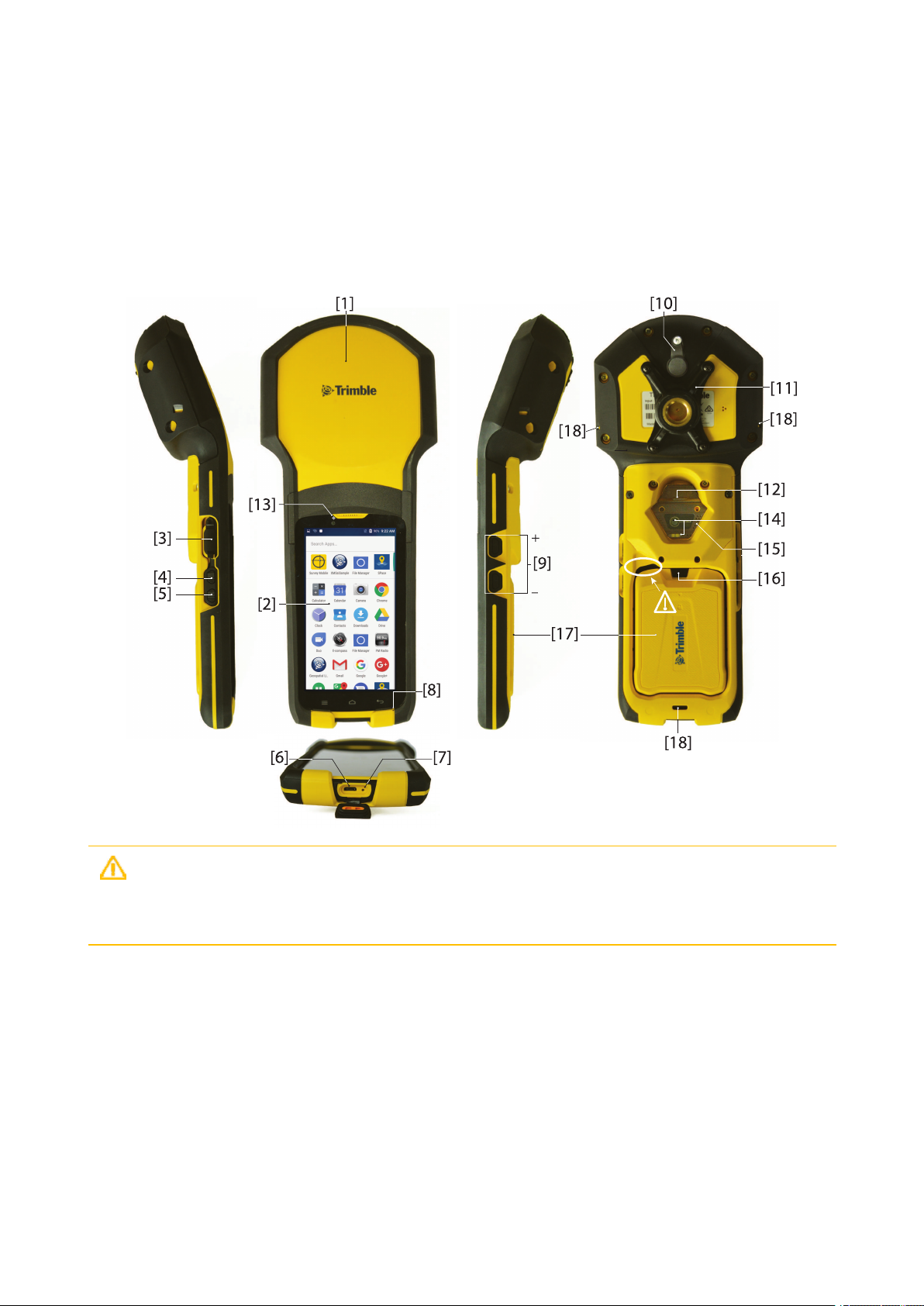
CAUTION – This recess is designed to ease battery door ejection using the battery door opener
provided (see First Time Use section). Please use this tool.Using any other means might damage the
battery door or the receiver case.
TDC150 User Guide | 12
Page 13
Discover Your Trimble TDC150 Handheld
[1]
[2] Android platform’s 5.3” color touch screen [11]
[3] Headphone plug (underneath protection flap) [12] Power button
[4] Programmable button A [13] Camera lens (front)
[5] Programmable button B [14] Camera lens (rear) and flash
[6] Micro USB (underneath protection flap) [15] Speaker
[7]
[8] Microphone [17] Battery door
[9] Volume control buttons [18]
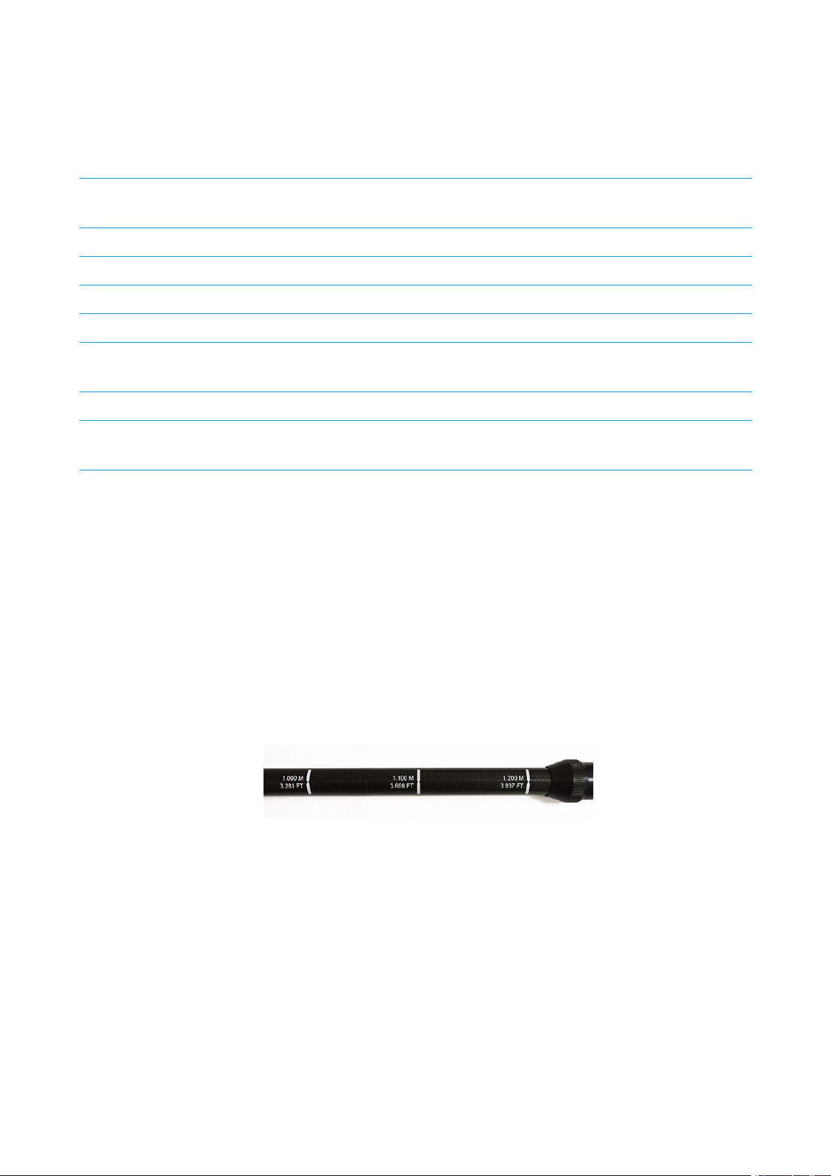
When the monopole is used, the antenna height (H) you need to specify in your application is the length of
the monopole(read the graduation on the monopole; see above picture).
Built-in, high-precision GNSS antenna and
receiver
Reset button (underneath same protection
flap)
[10] External GNSS antenna plug
Attachable/Detachable monopole
adapter
[16] Lock button
Three attachment points for
handstrap
The application will automatically add to H the distance (d) from the base of the monopole adapter to the
phase center so that the application uses the real height of the GNSS antenna phase center above the
ground.
Optional Accessories
Below is the list of optional accessories (Trimble reserves the right to make changes to this list without prior
notice):
1. Monopole (also known as half-pole):
Length is adjustable; three presettable lengths: 1.00 m (3.281 ft), 1.10 m (3.609 ft) and 1.20 m (3.937
ft).
TDC150 User Guide | 13
Page 14

Discover Your Trimble TDC150 Handheld
2. Pole bracket:
3. External antenna cable (a coaxial cable):
TDC150 User Guide | 14
Page 15

First-Time Use
First-Time Use
1. Unpacking
The following items are delivered in the box:
l TDC150 unit
l Li-Ion battery
l Universal power adapter (includes a USB-to-micro-USB cable)
l Quick Start Guide
l 2 x screen protectors
l Monopoleadapter (an attachable 5/8-inch female adapter + 4 x Philips head screws)
l Handstrap
l Battery door opener (a black, rigid pen-shaped accessory)
l Pouch.
NOTE –
Trimble reserves the right to make changes to this list without prior notice.
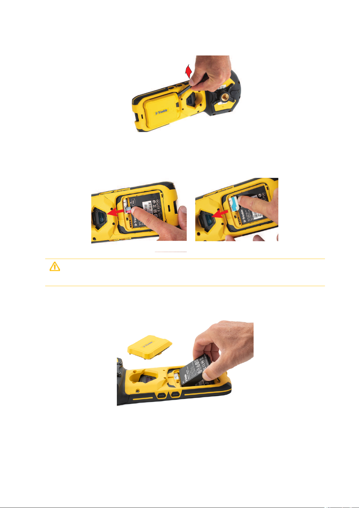
2. Inserting the SIM Card, Micro SD Card and Battery
Follow the instructions below:
1. Turn over the TDC150.
2. While exerting pressure on the battery door to ease the unlocking, slide out the lock using a finger or
the tip of the battery door opener.
3. Insert the tip of the battery door opener into the recess (top-left corner of the battery door, see also
Description, page 12) and gently push the opener to releasethe door out of the unit.
TDC150 User Guide | 15
Page 16
First-Time Use
[1] [2]
4. Put the battery door away.
5. If you are using a SIM card or/and a Micro SD card, insert these items now, BEFORE inserting the
battery, making sure these are oriented as instructed on the label, contact side facing down for each of
them. Insert the SD card first, then the SIM card.
CAUTION – For a micro or nano SIM card, please use a rigid, not a flexible SIM card adapter.
Flexible SIM card adapters may damage the SIM card slot.
6. Insert the battery as shown below. Orientate the battery so that its electric contacts come first into
contact with those at the bottom of the battery compartment. Insert the contacts side of the battery
first, as shown, then push the battery in.
(If you insert the battery the wrong way, the battery door won’t close.)
TDC150 User Guide | 16
Page 17

First-Time Use
7. Put the battery door back into place by first inserting the two lugs located at the bottom of the door
(opposite the lock).
8. Then push the battery door against the unit and lock it.
TDC150 User Guide | 17
Page 18

First-Time Use
[1]
[2]
[3]
[3]
[3]
[2]
[4]
3. Charging the Battery With the Universal Power Adapter
Follow the instructions below.
1. Prepare the power adapter:
- Choose the plug that fits your country’s AC outlet standard (see [1]).
- Slide it into the AC adapter [2]. (A “click” must be heard when fully inserted.)
2. Take the USB cable provided [3].
3. Connect the end fitted with a standard USB connector to the power adapter.
TDC150 User Guide | 18
Page 19

First-Time Use
4. Connect the other end (fitted with a micro-USB connector) to the bottom side of the TDC150 (open the
flap [4] first).
5. Connect the power adapter to an electric outlet. After about 4 seconds, the TDC150 screen will light up
showing a large battery icon being charged. The screen is then turned back off after about 10 seconds.
After this time, battery charging will continue at the same rate until the battery is fully charged (charging
time: 4 hours max.). The charger delivers a DC current of 2 A max. at 5 V DC.
6. To read the battery charging status, just press briefly the power button to re-activate the screen for the
next 10 seconds.
7. Unplug the charger from the TDC150 when battery charging is complete.
4. Turning On the TDC150 for the First Time
1. Press the Power button [12] (see Description, page 12) for a few seconds until the TDC150 vibrates,
then release the button.
2. Follow the on-screen instructions to initialize the receiver (choice of interface language, date, user name,
protection, Google account, etc.; some of these steps may be skipped).
5.Installing GNSS Loader
(See also Using GNSS Loader, page 28.)
This application is required to upgrade theTDC150 GNSS firmware and install accuracy options.
1. Using your officecomputer, go to:
https://www.trimble.com/globalTRLTAB.asp?nav=Collection-128273
2. From there, open the Applications menu and download this file:
GNSSLoader_Vx.x.xx.apk
3. Save the file (an apk file) on your computer.
4. Using a USB connection between your office computer and the TDC150, copy the apk file to a folder on
the TDC150.
5. From the File Manager application in Android, double-tap on the this apk file to install GNSS Loader. Let
the receiver complete the installation procedure.
TDC150 User Guide | 19
Page 20

First-Time Use
6. Checking/Updating TDC150 GNSS Firmware
Your TDC150 should always use the latest GNSS firmware.
1. On the TDC150, run GNSS Loader from the Android welcome screen.
2. Select About. GNSS Loader displays the version of the installed GNSS firmware on the third line. Write
down the version number.
Example: Firmware version 3.64
3. Using your officecomputer, go to:
https://www.trimble.com/globalTRLTAB.asp?nav=Collection-128273
4. From there, open the Firmware menu, and read the version number of the latest TDC150 GNSS
firmware available.
Example: Firmware TDC150_upgrade_v3.67.tar
If the version installed on the TDC150 is the same as the latest one available, skip the rest of this
procedure. If they are not, proceed with the next steps below.
5. Click on the link of the latest firware version: Firmware TDC150_upgrade_vx.xx.tar
6. Save the file (a tar file) on your computer.
Example: Firmware TDC150_upgrade_v3.67.tar
7. Still using the USB connection between your office computer and the TDC150, copy the tar file to the
Download folder on the TDC150. (Copying to the Download folder is mandatory.)
8. On the TDC150, run GNSS Loader from the Android welcome screen.
9. Select Upgrade firmware.
10.
Select the firmware upgrade file you have just downloaded and then touch . Let the receiver
complete the upgrade.
The whole sequence takes about 15 minutes. It can be split into three different steps: file copy (longest
step), firmware upgrade and receiver reset. Touch OK when the message Complete pops up.
7. Installing an Accuracy Option
If you purchased an accuracy option with your TDC150, make sure you have the POPN (Proof Of Purchase
Number) ready as you will need it in the next steps. Still with GNSS Loader running:
1. Select Install accuracy option.
2. Touch ADD, and then enter the POPN. Touch INSTALL to complete the installation.
(See also Using GNSS Loader, page 28.)
TDC150 User Guide | 20
Page 21

First-Time Use
8. Installing and Running your GIS Application
1. Using a USB connection between your office computer and the TDC150, copy the installation file (an
apk file) of your GIS application to a folder on the TDC150.
2. From the File Manager application in Android, double-tap on the this apk file to install your application.
Let the receiver complete the installation procedure.
3. Run your GIS application and start your work.You may need to use the handstrap (see below).
9. Attaching the Handstrap
The TDC150 can moresafely be hand-held using the handstrap (provided). The handstrap gives a better
grasp and eliminates the risk of accidentally dropping the unit to the ground.
First you should attach the two ends of the handstrap to the back of the TDC150. As shown below, there
aretwo ways of attaching it. You’ll choose one way or another, depending on whether you are left- or righthanded.
CAUTION – The ends of the handstrap are different. One is designed to be hooked to the center
bottom of the unit, and the other to the right or left side of the unit.
10. Turning Off TDC150
We recommend you neatly turn off the TDC150 as explained below, which will avoid losing data.
After you have finished your work, turn off the TDC150 by holding the Power button [12] pressed until a
dialog pops up, inviting you to either power off, reboot or switch the TDC150 to Airplane mode.
Touch Power off on the screen. This starts the power off procedure. Wait until the screen goes blank.
TDC150 User Guide | 21
Page 22

How to Hold the TDC150
How to Hold the TDC150
In Your Hand
This requires that you hold the TDC150 in an appropriate manner. The TDC150 will have the best view of
the sky if you hold it at waist level (or higher), at such an angle that the top of the unit (containing the GNSS
antenna; see [1], Description, page 12) is in horizontal position and not too closeto your body.
On Top of a Monopole
First attach the monopole adapter to the back of the unit. Use a Philips screwdriver and the four screws
provided to secure the adapter. Mount the TDC150 on top of the monopole (optional accessory).
The TDC150 will have the best view of the sky if you hold it not too close to your body.
TDC150 User Guide | 22
Page 23

How to Hold the TDC150
d
H
GNSS Antenna Height with Monopole
When used on top of the monopole accessory (see picture; the monopole adapter is secured to the back of
the TDC150, see also How to Hold the TDC150, page 22 ), the TDC150 can deliver accurate vertical
coordinates because the monopole gives the TDC150 excellent vertical stability.
TDC150 User Guide | 23
Page 24

How to Hold the TDC150
On a Pole With External GNSS Antenna
In cases where you wish to use an external GNSS antenna mounted on top of a pole, the TDC150 will be
inserted into a bracket (optional accessory) which you will fasten to the pole, approximately at mid-height.
You can freely orientate the TDC150 on its bracket since it is the external GNSS antenna, and not the
TDC150’s own antenna, that is used in this case.
Insert the TDC150 into the bracket so that it is pinched where you would normally hold it in your hand. That
way you keep the rear camera clear and preserve access to the Power button.
You may use one of the two notches in the bracket to attach the coaxial cable connecting the TDC150 to
the external GNSS antenna (see above picture), thus protecting the coaxial connector on TDC150 side from
been accidentally pulled out.
To remove the TDC150 from the bracket, hold the external jaw of the bracket firmly in one hand and
extract the TDC150 from the bracket using the other hand.
TDC150 User Guide | 24
Page 25

Usual Android Settings
Usual Android Settings
Literature about Android 6 can easily be found on the Internet. If you are new to Android, you may consult
this information on line. Below are suggestions of links you may use to learn more about Android 6:
https://www.cnet.com/how-to/roasting-marshmallow-your-guide-to-android-6-0/
https://www.android.com/versions/marshmallow-6-0/
Many other sources of information exist on the Internet that you can find by yourself.
This section only describes a few basic Android functions you may need to use while working with your
TDC150.
Choosing the Interface Language
From the Android welcome screen, touch then .
Scroll down to the Personal section and once visible, touch the line containing this icon: .
In the first field at the top of the screen, select your language.
Touch repeatedly to return to the Android welcome screen.
Setting Time & Date
Following a battery change in the field with no network connection, the Android time & date is likely to be
wrong (because not automatically updated). Although as soon as GNSS reception is re-established, raw data
(if recorded) will be properly time-tagged, on the other hand the creation time and date of the raw data file
will remain wrong.
If however you can temporarily get a WiFi or GSM connection from your TDC150, then you will allow the
Android time & date to be automatically updated.
But if this is not possible, we recommend you set the Android time and date manually before resuming your
work so that the files you will subsequently create are all properly dated.
l From the Android welcome screen, touch then .
l Scroll down to the System section and once visible, touch the linecontaining this icon: .
l Momentarily disable the Automatic date & time parameter and then enter successively the current
date and time in the fields located underneath.
l Then re-enable the Automatic date & time parameter.
l
Touch repeatedly to return to the Android welcome screen.
TDC150 User Guide | 25
Page 26

Usual Android Settings
Adjusting Time to Screen Sleep Mode
When using your TDC150 in the field, there may be long periods of time during which your TDC150 is
collecting data but there is no need for you to touch the screen during this time (for example you are
collecting a long line or polygon GIS feature). In this case you may want to keep the screen awake
throughout the logging sequence.
The default time for the screen to switch to sleep mode being only 1 minute of inactivity, you will probably
want to change this time. Here is how you can do this:
From the Android welcome screen, touch then .
l
Scroll down to the Device section and once visible, touch the line containing this icon: .
l Touch the fourth field (Sleep) and then choose the duration of inactivity at the end of which the screen
will turn blank. The longest timeyou may choose is 30 minutes of inactivity.
l
Touch repeatedly to return to the Android welcome screen.
NOTE –
The fact that the screen switches to sleep mode has no impact whatsoever on any data collection
sequence taking place in the TDC150.
Assigning Applications to the Programmable Buttons
(See programmable buttons A and B, Description, page 12.)
l
From the Android welcome screen, touch then .
l
Scroll down to the Personal section and once visible, touch the line containing this icon: (AB Key
Set).
l Touch button A or B at the top of the screen then tick one of the apps listed below that you want to
assign to the corresponding key (e.g. Calculator). Repeat this action for the other key if you wish (e.g. Ecompass).
l
Touch repeatedly to return to the Android welcome screen.
TDC150 User Guide | 26
Page 27

Usual Android Settings
Resetting TDC150
In the very unlikely case where your TDC150 would stop responding and a press on the power button
would have no effect, then you might conveniently use the reset button for a fresh restart of the unit
without having to temporarily remove the battery.
The reset button is that miniature button nested closeto the USB connector (see [7], Description, page 12).
To press this button use a thin, long and pointy tool, like for example a pencil or an unfolded paper clip.
After pressing the button, the TDC150 will simply restart. This action has no effect whatsoever on your
Android settings, your applications, files and personal data. It’s just a hardware reset.
TDC150 User Guide | 27
Page 28

Using GNSS Loader
Using GNSS Loader
This application is required whenever you need to update the TDC150’s GNSS firmware and/or if you have
purchased the TDC150 with better than one meter position accuracy. GNSS Loader will be used in the latter
case to install the corresponding firmware option.
To install GNSS Loader:
1. Using your officecomputer, go to:
https://www.trimble.com/globalTRLTAB.asp?nav=Collection-128273
2. From there, open the Applications menu and download this file:
GNSSLoader_Vx.x.xx.apk
3. Save the file (an apk file) on your computer.
4. Using a USB connection between your office computer and the TDC150, copy the apk file to a folder on
the TDC150.
5. From the File Manager application in Android, double-tap on the this apk file to install GNSS Loader. Let
the receiver complete the installation procedure.
6. Run GNSS Loader by touching this icon in the Android applications menu:
The GNSS Loader menu includes the following functions:
l Reset GNSS: Touch this option to reset the TDC150’s built-in, high-accuracy GNSS receiver. When the
sequence is complete, this message is displayed:
Complete
GNSS has been reset to the default settings
Touch OK to close the message dialog box and return to the main menu.
l Upgrade firmware: Opens a window listing the possible GNSS firmware upgrades currently stored in
the Download folder. These files use the following naming convention:
TDC150_upgrade_vx.xx.x.x.tar
Where vx.xx.x is the firmware version contained in the upgrade file.
(So you should have received your GNSS firmwareupgrade before using the Upgrade firmware
function.)
To install an upgrade select the file and then touch .
TDC150 User Guide | 28
Page 29

Using GNSS Loader
l Install accuracy option: Opens a window listing the currently installed accuracy options.
The ADD button located at the bottom of the screen allows you to install a new option after entering
the corresponding POPN.
The following screen appears after touching ADD:
If you have purchased your TDC150 with sub-meter, decimeter or centimeter accuracy, you should
have received the corresponding POPN via email.
Enter the POPN and touch INSTALL.
l Install service or other option: Same as Install accuracy option. This function needs a passcode.
l About: Returns the software version of the installed GNSSLoader application, the TDC150 unit serial
number and the version of the GNSS firmware currently installed in your TDC150. Touch OK to return
to the main menu.
TDC150 User Guide | 29
Page 30

Using SPace
Using SPace
SPace is the software interface required when running third-party Android applications on the TDC150.
SPace is mainly used to:
l Forward positioning information from the TDC150 high-accuracy GNSS module to any application
running on the TDC150 and using the Android mock location server.
l Process incoming corrections.
l Monitor both GNSS reception, corrections reception and position accuracy.
Installing SPace
1. Using your officecomputer, go to:
https://www.trimble.com/globalTRLTAB.asp?nav=Collection-128273
2. From there, open the Applications menu and download this file:
SPace_Vx.x.xx.apk
3. Save the file (an apk file) on your computer.
4. Using a USB connection between your office computer and the TDC150, copy the apk file to a folder on
the TDC150.
5. From the File Manager application in Android, double-tap on the this apk file to install SPace. Let the
receiver complete the installation procedure.
Starting SPace for the First Time
When launching SPace for the first time, a message will first ask you to read and accept the EULA
agreement. Another message will follow asking you to choose the application providing Android with
position information:
TDC150 User Guide | 30
Page 31

Using SPace
Touch Yes. This will open the list of developer options. Scroll down the screen until you find Select mock
location app in the Debugging section.
Touch Select mock location app. This opens a dialog listing the apps that can be used for this purpose.
Touch SPace. The screen then shows that your choiceis now active.
Touch to return to SPace (SKYPLOT tab displayed).
NOTE –
You need to do this setting only once.
CAUTION – Whenever you launch SPace, including the first time you do it, it takes about 4 seconds
before the TDC150 gets initialized. Meanwhile, the antenna icon in the SPace status bar looks like this:
When initialization is complete, this icon changes aspect to look like this:
TDC150 User Guide | 31
Page 32

Using SPace
Notes about the User Interface
You will find the following graphic objects in SPace. The table below explains what they are for and when
and how to use them:
Object Function
This is a switch: An empty circle stuck to the left means the concerned parameter is
disabled while an orange circle stuck to the right means it is enabled. To switch from
one state to the other, just touch the line including this graphic object or simply drag
the circle to the left or right.
This object is associated with the previous one. After making a choice with the above
switch, touch this button in the lower-right corner of the screen to save the change
or changes you’ve just made. This will take you to the previous screen.
Please wait when this animated object is displayed. That means the TDC150is being
interrogated and it takes a while before the requested information is returned.
Normally this item disappears after a few seconds.
TDC150 User Guide | 32
Page 33

Using SPace
Setting TDC150 to Receive Corrections
After the TDC150 has initialized, do the following to set it up (see also SPace Settings on page 13 to have a
global view of all the settings you can make in SPace):
l
In the status bar, touch
l Touch the Correction Information field. You are then requested to choose between different sources
of corrections:
Source of Corrections Meaning
SBAS Corrections will be received from an SBAS satellite.
NTRIP
Corrections will be received from a particular mount point part of an NTRIP
network, via the Internet.
DIP Corrections will be received from a base via the Internet.
RTX IP Not available.
RTX L-BAND Not available.
l Choose the desired source of corrections, and then touch the horizontal right arrow in the lower-right
corner of the screen.
1. If you chose SBAS: No additional setting is required.
2. If you chose NTRIP: The first time you want to make an NTRIP connection, there is no predefined
connection profile available. Touch the “+” symbol in the lower-left corner of the screen and then
enter the parameters of your NTRIP provider:
Friendly Name (max 20 chars): Freely choose a convenient name for this connection profile.
Host Name or IP Address (The host name should contain a valid domain name.)
Port Number
Touch the Get Source Table button to list the mount points available from this provider and
select one. If you remember the name of the mount point you want to use, you don’t need to
acquirethe source table: Just touch the Enter Mount Point button and type in the name of the
desired mount point.
Then enter your NTRIP credentials (User Name and Password).
Touch Connect at the bottom of the screen. At this point, SPace will initiate a network connection
to allow the TDC150 to receive corrections from the chosen NTRIP provider.
3. If you chose DIP: The first timeyou want to make a DIP connection, there is no predefined
connection profile available. Touch the “+” symbol in the lower-left corner of the screen and then
TDC150 User Guide | 33
Page 34

Using SPace
enter the parameters of your DIP provider:
Friendly Name (max 20 chars): Freely choose a convenient name for this connection profile.
Host Name or IP Address (The host name should contain a valid domain name.)
Port Number
Touch Connect in the lower part of the screen. At this point, SPacewill initiate a point-to-point
network connection to allow the TDC150 to receive corrections from the chosen static IP address.
NOTE –
Next time you turn on the TDC150 for a new working session, the last NTRIP or DIP network
connection made will be re-established automatically, provided you still have the required environment
(modem, Wi-Fi) to establish a network connection.
SPace Settings
l
In the status bar, touch .
l Set the following parameters:
- Autostart application at boot: Enabling this parameter means SPace will be started
automatically next time you power on your TDC150. This way, you don’t have anything else to do at
power up, but start your application as soon as the TDC150is ready to operate. If you disable this
parameter, SPace will run only if you start it manually.
- Receiver (a read-only field): Displays the product name (“TDC150").
- Correction Information: Source of corrections currently used. If you touch this line, you may
change the type of connection through which corrections enter the TDC150 (SBAS, NTRIP, DIP; see
Setting TDC150 to Receive Corrections, page 33 for all the details). By touching the “+” symbol after
selecting “NTRIP” or “DIP”, you may add a new NTRIP or DIP provider respectively.
- Use monopole: By activating this function, you allow the TDC150 to deliver 3D positioning, the
height of the TDC150 above the ground being accurately known in that case.
- External antenna model (only if an external GNSS antenna is connected to the TDC150 via plug
[10] (see Description, page 12): Choose the model of external GNSS antenna used from the
available list (possible antenna models are111660, 111661, SPGA Rover, Zephyr 3 Rover).
Logically, when this option is visible in Settings, then Use monopole (above) is not.
- Configuration File: Allows you to run a file containing a set of commands intended to modify the
configuration of the high-accuracy GNSS module. The file should be a text file with the “txt”
extension and should have been saved to the Download folder. To have the receiver executing the
desired set of commands, just touch the txt file containing this set of commands. The response of
the high-accuracy GNSS module to the set of commands will be returned in a file named “<file_
name>.txt.log”, also visible in the Download folder.
TDC150 User Guide | 34
Page 35

Using SPace
- RF Band selection: Touch this parameter to choose which GNSS frequencies to receive (L1, L2, LBand). L1 and L2 are enabled by default and L-Band is disabled by default. L1 cannot be disabled.
- Constellation tracking: Touch this parameter to choose which constellations to receive (GPS,
GLONASS, Galileo, SBAS, BeiDou, QZSS). By default, all constellations are used (enabled).
- Debug Data Recording: Enable or disable the automatic recording of ATL data (debug data).
Enabling this function makes sense only if Technical Support requires that you do so. Otherwise
keep it disabled. Debug data will be saved as an ATL_yymmdd_hhmmss.log file stored in folder:
.../Download/ATL Data/
e.g. ATL180524_141126.log created at 2:11:26pm on May 23, 2018.
- Keep NMEA outputs running: When enabled, this option makes sure all the NMEA messages
delivered by the GNSS receiver to SPace continue to be output while SPace is running and after
SPace has stopped running.
- Help: Touch this line to open the Help page. Use the Back key on the TDC150 to closethe Help
page.
- About: Touch this line to read the installed SPace software version.
TDC150 User Guide | 35
Page 36

Using SPace
[1]
[4]
[2] [3]
[5] [6][7]
Monitoring TDC150 Operation
Operating Status Screens
The SKYPLOT tab ([1]) is a polar diagram showing the location in the sky of each tracked satellite.
Touch Legend ([4]) to read the color convention used for each constellation to represent satellite locations
on the skyplot view:
TDC150 User Guide | 36
Page 37

Using SPace
In the lower part of the screen, you can read the total number of currently tracked satellites and total
number of satellites currently used.
The POSITION INFORMATION tab ([2]) provides the following information, from top to bottom:
l Receiver name (TDC150)
l Latitude and Longitude of current position
l Altitude of current position
l Geoidal separation (vertical distancebetween datum used and geoid used)
l HRMS, VRMS: Horizontal and vertical errors
l Speed: TDC150 speed, in meters/second
l Fix quality: Position computation mode (AUTONOMOUS, DGPS, FLOAT RTK, FIXED RTK).
The CORRECTION INFORMATION tab ([3]) provides the following information, from top to bottom:
l Host Name or IP Address: Identification of the NTRIP or DIP server providing the corrections used.
l Port Number: IP port number of the NTRIP or DIP server providing the corrections used (blank for
SBAS) (the presence of a hyphen in any field means “Blank”).
l Type: Type of connection used (SBAS, NTRIP or DIP) to let the TDC150 acquire corrections.
l Mount Point: Name of mount point used in NTRIP (blank for SBAS and DIP).
l Network: Indicates which medium (Mobile or Wi-Fi) is used to make a network connection (blank for
SBAS).
l In the same line:
- Age: Age of the corrections received, in seconds.
- Station ID: Identification number of the station, or PRN of satellite in SBAS, providing the
corrections used.
l Status: Network connection status (Connected or Disconnected) (Blank if SBAS).
TDC150 User Guide | 37
Page 38

Using SPace
Receiver Profile Status
: Touch this icon (see [5] Description, page12) to read information about the TDC150:
l Receiver Type: “TDC150”.
l GNSS Connection Status: “Connected” necessarily. At power up, as long as this connection is not
active, you cannot open this window. The receiver icon then looks like this:
NOTE –
l RTX Subscription: Not available.
l MSL version: Software version of TDC150 Micro Service Layer. (This piece of software is used
After launching SPace, it takes about 4 seconds before this connection is active.
to interface TDC150 with Android).
l RTK Option: Indicates the level of precision available from your TDC150:
- Full RTK (centimeter accuracy): Centimeter-accurate 3D position
- 7/2 (decimeter accuracy): Accuracy is 7 cm in horizontal and 2 cm in vertical
- 30/30 (sub-meter accuracy): Accuracy is 30 cm in both horizontal and vertical.
l RTX Option: (“None” is displayed).
NOTE –
RTK options may have temporary validity (1 month).
TDC150 User Guide | 38
Page 39

Using SPace
Settings
See SPace Settings, page 34.
External GNSS Antenna
: This icon (see [7] Operating Status Screens, page 36) is shown only if an external GNSS antenna has
been connected to the TDC150 (see plug [10] Description, page 12).
If you touch this icon, you will be able to read the connection status and the signal level, as received by this
antenna.
SPace vs.GNSS Loader
Start GNSS Loader1(see Using GNSS Loader, page 28) which be possible only if SPace is NOT running.If
SPace is currently running, do the following to quit SPace:
l Touch the SPace icon (below left) in the Android applications menu, or touch this icon (see below right)
in the Android notification bar.This opens the SPace window on the TDC150 screen.
l
Quit SPace by touching .
1
Or any other application having direct control over the TDC150 high-accuracy GNSS module.
TDC150 User Guide | 39
Page 40

Using CamCal
Using CamCal
Why is TDC150 Rear Camera Calibration Required?
The main purpose of the TDC150 rear camera is to provide an accurate view of the ground below the
TDC150.
TDC150 Rear Camera
However a misalignment of the camera with the body of the TDC150 unit usually exists introducing a bias in
all measurements made. This will be the case for example when using the rear camera to log data from
within the TerraFlex GIS application.
What’s more, the degree of misalignment varies from TDC150 to another, thus making the bias a quantity
specific to each TDC150 unit.
For this reason, Trimble has developed the CamCal application so that users can eliminate the biases specific
to their own TDC150 units. CamCal has to be run individually on each TDC150 to make the bias
determination accurate.
CamCal Icon
The calibration process has to be performed once, but needs to be repeated every 3 or 6 months,
depending on how often you use your TDC150.
The overall calibration process only takes a few minutes.
TDC150 User Guide | 40
Page 41

Using CamCal
Required Accessory
The Trimble monopole, or any other pole, is required to perform the calibration.
You will have to change the monopole length twice during the process and the difference between the two
lengths should be at least 20 cm.
With its four preset lengths, from 1.00 m to 1.30 m, the Trimble monopole (see picture) appears to be the
best option for this procedure.
Calibration Principle
During the calibration process, you will have to take two pictures using the rear camera. These will be taken
at two different lengths of the monopole, onto which you will have first installed your TDC150 unit.
After shooting each of the two pictures, CamCal will ask you to drag it on the screen so that the tip of the
monopole appears at the center of a cross-hair, which occupies a fixed, central position on the screen.
After you have made this adjustment for each of the two pictures, CamCal will be ableto determine the bias,
which will subsequently allow your application to correct all their measurements for this bias.
TDC150 User Guide | 41
Page 42

Using CamCal
What is Required for Calibration
l The two pictures should be shot in portrait orientation to make them usable in the calibration process.
For some reason, the picture you will shoot may mistakenly be interpreted as a landscape image. In that
case, reject the picture and take a new one after giving more tilt to the monopole.
l The camera lens must be focused on the tip of the monopole. Before taking the picture touch the tip,
where seen on the screen, so that the camera can focus on this point. This is to make sure the picture
will not be blurred around this point.
l The tip of the monopole should be put down on the ground. This will give better mechanical stability to
the assembly and therefore better quality for your pictures.
To help you locate the tip of the monopole on the two pictures, it is a good idea to draw two
intersecting and perpendicular lines on the ground. By placing the tip of the monopole precisely at their
intersection point, it will be easier to place the tip (hidden on the pictures) at the center of the cross-hair
(more details in step 12, page 5).
What is not Required for Calibration
l You don’t need to hold the monopole in vertical position. On the contrary, giving some angle to the
monopole is recommended to prevent the camera from mistakenly interpreting the picture as one in
landscape format.
Camera Calibration Steps
CamCal can be downloaded through this link:
https://www.trimble.com/globalTRLTAB.asp?nav=Collection-128273
From there, open the Applications menu and download CamCal-x.xxx.apk.
After downloading and installing CamCal on your TDC150, do the following:
1. Secure the adapter onto the back of the TDC150. This accessory is part of the standard supply. Then
fasten the TDC150 with its adapter onto the monopole.
2. Set the monopole length to one of the possible four height values. Keep in mind the value you have just
set.
TDC150 User Guide | 42
Page 43

Using CamCal
3. Turn on the TDC150 and then put down the monopole on the ground, its tip placed exactly at the
intersection of two intersecting and perpendicular lines drawn on the ground.
4.
On the Android applications screen, touch .
This starts CamCal. A message then shows up (see below) recalling you to first install the TDC150 on a
monopole, which you have just done.
The second part of the message explains the two steps of the process.
5.
Click located in the lower-right corner of the screen. A new screen is displayed.
6. Enter the height value you’ve just set for the monopole.
7.
Touch located in the lower-right corner of the screen.
8. Accept the two settings that follow, each time by touching ALLOW (You will be asked only once).
Then the screen shows what the rear camera really sees.
TDC150 User Guide | 43
Page 44

Using CamCal
9. Touch the screen where the tip of the monopole is located in order to let the camera focus on that
point. A symbol shows where the camera is focusing on:
10. Take the first picture by touching . As a result, CamCal shows the picture you’ve just taken. CamCal will
show either a picture taken in portait or landscape format.
11.
Touch to accept the portrait format, or to reject the picture in landscape format. In the latter
case, change the tilt of the monopole and/or make a step to get a different view on the camera and
then take another picture to get a valid one.
With a valid picture, the next screen shows the picture you have just taken with a superimposed green
cross-hair at the center of the screen.
TDC150 User Guide | 44
Page 45

Using CamCal
12. Touch the screen with a finger and drag the picture so that the monopole tip appears at the center of
the cross-hair. Use the lines drawn on the ground to make this adjustment as accurate as possible (see
example below).
13.
Touch after you have been able to place the monopole tip within the cross-hair. A new screen is
displayed:
14. Change the length of the monopole (by more than 20 cm compared to the first height setting).
15. Resume the procedure from step 6 above. In step 6, enter the new height value, different from the first
one by more than 20 cm.
Step 8 will be skipped this time as the two questions of step 8 only have to be answered once.
TDC150 User Guide | 45
Page 46

Using CamCal
After the second picture has been taken, you have repositioned the monopole tip at the center of the
cross-hair and touched the to-the-right red arrow, a messagewill appear to inform you that the
“Calibration [is] complete”.
From now on, all data collection performed using the camera view will be corrected for the bias due to
bad camera alignment.
16.
Touch to quit CamCal.
Once the calibration is complete, you can be surethe view provided by the rear camera and the antenna
height entered in the application match up. This will guarantee that the accuracy of all your
measurements only depend on the accuracy of the GNSS position calculation.
TDC150 User Guide | 46
Page 47

Specifications
Specifications
GNSS Characteristics
l 240 GNSS channels:
- GPS L1, L2 (L1 C/A, L1P, L2P/ L2C
- GLONASS G1, G2 FDMA
- BeiDou B1 (phase 2 and phase 3), B2 (phase 2)
- Galileo E1, E5b
- QZSS L1C/A, L2C, L1Z
- SBAS L1C/A
- L-Band: 2 channels
l Scalable accuracy, from meter to centimeter [meter, sub-meter (30/30), decimeter (7/2), centimeter (full
RTK)].
l Patented Z-Blade technology for optimal GNSS performance:
- Full utilization of signals from all 6 GNSS systems (GPS, GLONASS, BeiDou, Galileo, QZSS and SBAS).
- Enhanced GNSS-centric algorithm: fully-independent GNSS signal tracking and optimal data
processing, including GPS-only, GLONASS-only or BeiDou-only solution (autonomous to full RTK).
- Fast search engine for quick acquisition and re-acquisition of GNSS signals.
l Patented SBAS ranging for using SBAS code & carrier observations and orbits in RTK Processing.
l Patented Strobe™ Correlator for reduced GNSS multi-path.
l Supported data formats: ATOM, CMR, CMR+, RTCM 2.1, 2.3, 3.0, 3.1 and 3.2 (including MSM), CMRx
and sCMRx.
Real-Time Accuracy
(1) (2)
(RMS)
SBAS (WAAS/EGNOS/MSAS/GAGAN):
l Horizontal: < 50 cm
l Vertical: < 85 cm
Real-Time DGPS position):
TDC150 User Guide | 47
Page 48

Specifications
l Horizontal: 25 cm + 1 ppm
l Vertical: 50 cm + 1 ppm
Real-Time Kinematic Position (RTK)
l Horizontal: 10 mm + 1 ppm
l Vertical: 15 mm + 1 ppm
(3)
:
Real-Time Performance
l Instant-RTK® Initialization:
- Typically 2 sec for baselines < 20 km
- Up to 99.9% reliability
l RTK initialization range: over 40 km.
Post-Processing Accuracy
(1) (2)
(RMS)
Static & Fast Static:
l Horizontal: 3 mm + 0.5 ppm
l Vertical: 5 mm + 0.5 ppm
High-Precision Static
l Horizontal: 3 mm + 0.1 ppm
l Vertical: 3.5 mm + 0.4 ppm
(4)
:
Data Logging Characteristics
Recording interval:
l 1 - 999 seconds
TDC150 User Guide | 48
Page 49

Specifications
Processor
l Qualcomm Snapdragon 410
l Quad-core
l Clock frequency: 1.2 GHz
Operating System
l Android® 6.0 (Google certified)
l Languages available: Afrikaans, German, English, Spanish, French, Italian, Portuguese (Portugal and
Brazil), Japanese, Korean, Simplified Chinese, Greek, Russian, Azebaijani, Czech, Danish, Lithuanian,
Hungarian, Dutch, Norwegian (Bokmal), Romanian, Finnish, Swedish, Turkish, Bulgarian, Serbian
(Cyrillic), Hindi, Polish.
l Software package includes Google Mobile Services.
Memory
l 2 GB SDRAM
l Storage: 16 GB (non volatile).
l MicroSDHC™ memory card (up to 64 GB, SanDisk®, KingstonR recommended).
Communications
l Cellular:
- GSM (850,900,1800,1900), GPRS, EDGE, UMTS, WCDMA (B1, B2, B5, B8), HSPA, TDSCDMA (B34,
B39), LTE-FDD (B1, B3, B4, B5, B7, B8, B20), LTE-TDD (B38/B39/ B40/B41)
l Wi-Fi (IEEE) 802.11 b/g/n
l Bluetooth 4.0 dual mode
l USB (micro B USB connector)
l NFC.
TDC150 User Guide | 49
Page 50

Specifications
Interface
l USB 2.0 (micro)
l External GNSS antenna connector (TNC)
l Audio jack 2.5 plug (CTIA/AHJ standards).
Environmental Characteristics
l Operating temperature: -20° to +60°C (-4 to 140°F)
l Storage temperature: -30° to +70°C without battery (-22 to 158°F) (5)
l Humidity: 95% non condensing
l Water & dust proof: IP67
l Free drop: 1.2 m on concrete
l Shocks: MIL STD 810 (fig 516.5-10) (01/2000)
l Vibration: MIL-STD-810F (fig 514.5C-17) (01/2000)
Power Characteristics
l Battery Li-Ion, 6400mAh
l Battery life: > 8 hrs @ 20 °C with GNSS on
l Charging time: 4 hours
l Removable battery.
Physical Characteristics
Size
l 29.5 x 12 x 4.5 cm (11.6 x 4.7 x 1.8 in)
Weight
l 850 g (1.87 lb)
User Interface
l 2 volume keys, on/off/reset key, 2 programmablekeys, standard Android touch panel buttons
l On screen keyboard display
TDC150 User Guide | 50
Page 51

Specifications
l Size: 5.3” capacitive multi touch
l Resolution: 1280 x 720 pixels
l Brightness: 450 Cd/m²
l Gorilla Glass damage-resistant
l Auto-rotate between Portrait and Landscape.
Multi-Media & Sensors
l Rear camera, 13 megapixels, with flash light
l Front camera, 2 megapixels
l E-Compass
l G-sensor
l Speaker
l Microphone
l Light sensor.
Standard Accessories
l Handstrap
l Screen protectors (x2)
l A/C charger
l USB cable
l Pouch
l Battery door opener
l Monopoleadapter
Optional Accessories
l External GNSS antenna
l Pole bracket
l Monopole.
TDC150 User Guide | 51
Page 52

Specifications
Operating Modes
l RTK rover: Direct IP, NTRIP (VRS, FKP, MAC networks)
l Post-processing.
Field Software
l TerraFlex
l PenMap
(1)
Accuracy and TTFF specifications may be affected by atmospheric conditions, signal multipath, satellite geometry
and corrections availability and quality.
(2)
Performance values assume minimum of five satellites, following the procedures recommended in the product
manual. High multipath areas, high PDOP values and periods of severe atmospheric conditions may degrade
performance. Real-time accuracy depends on the TDC150 accuracy option installed. Post-processing (PP) accuracy
obtained with ATOM files processed by SPSO.
(3)
TDC150 used with monopole accessory.
(4)
Long baselines, long occupations, precise ephemeris used.
(5)
Battery can be stored up to +70°C.
(6)
Receiver convergence time varies based on GNSS constellation health, level of multipath, and proximity to
obstructions such as large trees and buildings. Convergence can be improved in RAM enabled regions.
TDC150 User Guide | 52
 Loading...