

Page 1
Trimble S, VX, SPS & RTS
F
Total Station
Service Manual
February 2010 P/N 57150002, Revision 5.0
Page 2

F
Trimble S, VX, SPS & RTS Service ManualII P/N 57150002, Revision 5.0
Page 3

F
Table of Contents
Table of Contents
1 General Information and safety . . . . . . . . . . . . . . . . . . . . . . . . 1-1
Statement of Disclamation . . . . . . . . . . . . . . . . . . . . . . . . . . . . . . . . . . . 1-2
Preface . . . . . . . . . . . . . . . . . . . . . . . . . . . . . . . . . . . . . . . . . . . . . . 1-3
Basic Assumptions . . . . . . . . . . . . . . . . . . . . . . . . . . . . . . . . . . . . . . . 1-4
General Safety . . . . . . . . . . . . . . . . . . . . . . . . . . . . . . . . . . . . . . . . . . 1-5
Electrostatic Discharge (ESD) . . . . . . . . . . . . . . . . . . . . . . . . . . . . . . . . . . 1-6
Laser Safety . . . . . . . . . . . . . . . . . . . . . . . . . . . . . . . . . . . . . . . . . . . 1-8
Service procedure recommendations . . . . . . . . . . . . . . . . . . . . . . . . . . . . . .1-27
Measuring through glass window . . . . . . . . . . . . . . . . . . . . . . . . . . . . . . . .1-28
2 General Product Information . . . . . . . . . . . . . . . . . . . . . . . . . . 2-1
Trimble S3 - Product description & Service Information . . . . . . . . . . . . . . . . . . . . 2-2
Trimble S6 - Product description & Service information . . . . . . . . . . . . . . . . . . . . 2-3
Trimble S8 - Product description & Service information . . . . . . . . . . . . . . . . . . . . 2-4
Trimble VX - Product description & Service information . . . . . . . . . . . . . . . . . . . 2-6
Trimble RTS - Product description & Service information . . . . . . . . . . . . . . . . . . . 2-7
Trimble SPS - Product description & Service information . . . . . . . . . . . . . . . . . . . 2-8
Models and serial numbers . . . . . . . . . . . . . . . . . . . . . . . . . . . . . . . . . . .2-10
Instrument Model Matrix . . . . . . . . . . . . . . . . . . . . . . . . . . . . . . . . . . . .2-14
Product Specifications . . . . . . . . . . . . . . . . . . . . . . . . . . . . . . . . . . . . . . 2-16
Model definition . . . . . . . . . . . . . . . . . . . . . . . . . . . . . . . . . . . . . . . . .2-17
3 Theory of Operation . . . . . . . . . . . . . . . . . . . . . . . . . . . . . . . 3-1
Instrument . . . . . . . . . . . . . . . . . . . . . . . . . . . . . . . . . . . . . . . . . . . . 3-2
Removable handle . . . . . . . . . . . . . . . . . . . . . . . . . . . . . . . . . . . . . . . . 3-7
Battery / radio side cover . . . . . . . . . . . . . . . . . . . . . . . . . . . . . . . . . . . . 3-8
Radio unit . . . . . . . . . . . . . . . . . . . . . . . . . . . . . . . . . . . . . . . . . . . . 3-11
Servo side cover . . . . . . . . . . . . . . . . . . . . . . . . . . . . . . . . . . . . . . . . .3-14
IPC board . . . . . . . . . . . . . . . . . . . . . . . . . . . . . . . . . . . . . . . . . . . . 3-17
TCU attachment . . . . . . . . . . . . . . . . . . . . . . . . . . . . . . . . . . . . . . . . .3-20
TCU attachment with USB . . . . . . . . . . . . . . . . . . . . . . . . . . . . . . . . . . .3-22
Control Panel . . . . . . . . . . . . . . . . . . . . . . . . . . . . . . . . . . . . . . . . . . 3-24
Face2 panel & optical plummet . . . . . . . . . . . . . . . . . . . . . . . . . . . . . . . . .3-27
Pressure sensor . . . . . . . . . . . . . . . . . . . . . . . . . . . . . . . . . . . . . . . . . 3-30
Servo drive system . . . . . . . . . . . . . . . . . . . . . . . . . . . . . . . . . . . . . . .3-31
Angle Measuring System . . . . . . . . . . . . . . . . . . . . . . . . . . . . . . . . . . . .3-36
Base unit . . . . . . . . . . . . . . . . . . . . . . . . . . . . . . . . . . . . . . . . . . . . .3-43
PSM board . . . . . . . . . . . . . . . . . . . . . . . . . . . . . . . . . . . . . . . . . . . . 3-46
Tilt sensor . . . . . . . . . . . . . . . . . . . . . . . . . . . . . . . . . . . . . . . . . . . .3-48
Software / Instrument application firmware . . . . . . . . . . . . . . . . . . . . . . . . . . . 3-52
Telescope . . . . . . . . . . . . . . . . . . . . . . . . . . . . . . . . . . . . . . . . . . . .3-62
Distance unit - DR300+ / DR PLUS . . . . . . . . . . . . . . . . . . . . . . . . . . . . . . 3-65
Distance unit - High Precision / DR Standard / DR . . . . . . . . . . . . . . . . . . . . . . .3-73
Tracklight . . . . . . . . . . . . . . . . . . . . . . . . . . . . . . . . . . . . . . . . . . . .3-79
Tracker system . . . . . . . . . . . . . . . . . . . . . . . . . . . . . . . . . . . . . . . . .3-81
Servo focus . . . . . . . . . . . . . . . . . . . . . . . . . . . . . . . . . . . . . . . . . . .3-87
Video camera (Trimble S8 / VX) . . . . . . . . . . . . . . . . . . . . . . . . . . . . . . . .3-90
P/N 57150002, Version 5.0 III Trimble S, VX, SPS & RTS Service Manual
Page 4

F
Auto focus . . . . . . . . . . . . . . . . . . . . . . . . . . . . . . . . . . . . . . . . . . . .3-95
Tracker Long Range - TLR . . . . . . . . . . . . . . . . . . . . . . . . . . . . . . . . . . .3-96
High Power Laser Pointer - HPL . . . . . . . . . . . . . . . . . . . . . . . . . . . . . . . 3-102
Service interval . . . . . . . . . . . . . . . . . . . . . . . . . . . . . . . . . . . . . . . . 3-104
Board definitions . . . . . . . . . . . . . . . . . . . . . . . . . . . . . . . . . . . . . . . 3-105
Table of Contents
4 Troubleshooting . . . . . . . . . . . . . . . . . . . . . . . . . . . . . . . . . 4-1
Save Event log . . . . . . . . . . . . . . . . . . . . . . . . . . . . . . . . . . . . . . . . . . 4-2
Clear Event log . . . . . . . . . . . . . . . . . . . . . . . . . . . . . . . . . . . . . . . . . 4-3
Basic Function test . . . . . . . . . . . . . . . . . . . . . . . . . . . . . . . . . . . . . . . 4-4
Distance and Angles Logging . . . . . . . . . . . . . . . . . . . . . . . . . . . . . . . . . .4-10
Troubleshooting guide . . . . . . . . . . . . . . . . . . . . . . . . . . . . . . . . . . . . . . 4-13
Angle and servo unit . . . . . . . . . . . . . . . . . . . . . . . . . . . . . . . . . . . . . . .4-20
Distance unit . . . . . . . . . . . . . . . . . . . . . . . . . . . . . . . . . . . . . . . . . . .4-21
Tracker unit . . . . . . . . . . . . . . . . . . . . . . . . . . . . . . . . . . . . . . . . . . .4-22
5 Maintenance and Repair . . . . . . . . . . . . . . . . . . . . . . . . . . . . 5-1
Distance and Tracker unit covers . . . . . . . . . . . . . . . . . . . . . . . . . . . . . . . . 5-3
Side covers . . . . . . . . . . . . . . . . . . . . . . . . . . . . . . . . . . . . . . . . . . . 5-6
Handle . . . . . . . . . . . . . . . . . . . . . . . . . . . . . . . . . . . . . . . . . . . . . . 5-8
Battery/Radio side cover . . . . . . . . . . . . . . . . . . . . . . . . . . . . . . . . . . . . 5-10
Servo side cover . . . . . . . . . . . . . . . . . . . . . . . . . . . . . . . . . . . . . . . . .5-15
IPC board . . . . . . . . . . . . . . . . . . . . . . . . . . . . . . . . . . . . . . . . . . . . 5-17
TCU attachment with USB . . . . . . . . . . . . . . . . . . . . . . . . . . . . . . . . . . .5-20
Face 1 Cover . . . . . . . . . . . . . . . . . . . . . . . . . . . . . . . . . . . . . . . . . . . 5-23
Control Panel . . . . . . . . . . . . . . . . . . . . . . . . . . . . . . . . . . . . . . . . . . 5-24
Face 2 panel . . . . . . . . . . . . . . . . . . . . . . . . . . . . . . . . . . . . . . . . . . .5-38
Face 2 Cover . . . . . . . . . . . . . . . . . . . . . . . . . . . . . . . . . . . . . . . . . . . 5-42
Vertical servo motor & angle unit . . . . . . . . . . . . . . . . . . . . . . . . . . . . . . . . 5-44
Regreasing of centre unit axes . . . . . . . . . . . . . . . . . . . . . . . . . . . . . . . . . .5-50
Base unit . . . . . . . . . . . . . . . . . . . . . . . . . . . . . . . . . . . . . . . . . . . . .5-54
Horizontal servo motor & angle unit . . . . . . . . . . . . . . . . . . . . . . . . . . . . . . 5-59
PSM board . . . . . . . . . . . . . . . . . . . . . . . . . . . . . . . . . . . . . . . . . . . . 5-65
Tilt sensor . . . . . . . . . . . . . . . . . . . . . . . . . . . . . . . . . . . . . . . . . . . .5-67
Reticle . . . . . . . . . . . . . . . . . . . . . . . . . . . . . . . . . . . . . . . . . . . . . . 5-69
Distance unit - DR300+ / DR PLUS . . . . . . . . . . . . . . . . . . . . . . . . . . . . . . 5-72
Reticle Illumination . . . . . . . . . . . . . . . . . . . . . . . . . . . . . . . . . . . . . . . 5-83
Laser pointer - DR300+ / DR PLUS . . . . . . . . . . . . . . . . . . . . . . . . . . . . . . 5-87
Distance unit - High Precision / DR Standard . . . . . . . . . . . . . . . . . . . . . . . . . . 5-91
Distance unit - DR . . . . . . . . . . . . . . . . . . . . . . . . . . . . . . . . . . . . . . . 5-107
Tracker unit . . . . . . . . . . . . . . . . . . . . . . . . . . . . . . . . . . . . . . . . . . 5-110
Tracklight . . . . . . . . . . . . . . . . . . . . . . . . . . . . . . . . . . . . . . . . . . . 5-113
Servo focus . . . . . . . . . . . . . . . . . . . . . . . . . . . . . . . . . . . . . . . . . . 5-116
S8 / VX - Camera module . . . . . . . . . . . . . . . . . . . . . . . . . . . . . . . . . . . 5-121
Tracker Long Range - TLR . . . . . . . . . . . . . . . . . . . . . . . . . . . . . . . . . . 5-127
High Power Laser Pointer - HPL . . . . . . . . . . . . . . . . . . . . . . . . . . . . . . . 5-130
Autolock upgrade . . . . . . . . . . . . . . . . . . . . . . . . . . . . . . . . . . . . . . . 5-135
Robotic upgrade . . . . . . . . . . . . . . . . . . . . . . . . . . . . . . . . . . . . . . . . 5-139
FineLock upgrade . . . . . . . . . . . . . . . . . . . . . . . . . . . . . . . . . . . . . . . 5-142
Scanning upgrade . . . . . . . . . . . . . . . . . . . . . . . . . . . . . . . . . . . . . . . 5-145
Trimble S, VX, SPS & RTS Service ManualIV P/N 57150002, Version 5.0
Page 5

F
What to do after replacement . . . . . . . . . . . . . . . . . . . . . . . . . . . . . . . . . 5-148
Table of Contents
6 Adjustment and verification . . . . . . . . . . . . . . . . . . . . . . . . . . 6-1
Battery/radio side cover . . . . . . . . . . . . . . . . . . . . . . . . . . . . . . . . . . . . . 6-2
Servo side cover . . . . . . . . . . . . . . . . . . . . . . . . . . . . . . . . . . . . . . . . . 6-5
IPC board - instrument data . . . . . . . . . . . . . . . . . . . . . . . . . . . . . . . . . . . 6-6
TCU attachment . . . . . . . . . . . . . . . . . . . . . . . . . . . . . . . . . . . . . . . . .6-13
TCU Attachment with USB . . . . . . . . . . . . . . . . . . . . . . . . . . . . . . . . . . .6-14
Control Panel . . . . . . . . . . . . . . . . . . . . . . . . . . . . . . . . . . . . . . . . . . 6-17
Face 2 panel . . . . . . . . . . . . . . . . . . . . . . . . . . . . . . . . . . . . . . . . . . .6-20
Optical plummet . . . . . . . . . . . . . . . . . . . . . . . . . . . . . . . . . . . . . . . . .6-22
Pressure sensor . . . . . . . . . . . . . . . . . . . . . . . . . . . . . . . . . . . . . . . . . 6-24
Servo unit . . . . . . . . . . . . . . . . . . . . . . . . . . . . . . . . . . . . . . . . . . . .6-25
Angle unit . . . . . . . . . . . . . . . . . . . . . . . . . . . . . . . . . . . . . . . . . . . .6-28
Base unit . . . . . . . . . . . . . . . . . . . . . . . . . . . . . . . . . . . . . . . . . . . . .6-30
Firmware upgrade . . . . . . . . . . . . . . . . . . . . . . . . . . . . . . . . . . . . . . . .6-31
Collimator alignment . . . . . . . . . . . . . . . . . . . . . . . . . . . . . . . . . . . . . . 6-32
Reticle . . . . . . . . . . . . . . . . . . . . . . . . . . . . . . . . . . . . . . . . . . . . . . 6-33
Laser pointer - DR300+ / DR PLUS . . . . . . . . . . . . . . . . . . . . . . . . . . . . . . 6-51
Distance unit - DR300+ / DR PLUS . . . . . . . . . . . . . . . . . . . . . . . . . . . . . . 6-59
Distance unit - High Precision / DR Standard / DR . . . . . . . . . . . . . . . . . . . . . . .6-88
Tracker unit . . . . . . . . . . . . . . . . . . . . . . . . . . . . . . . . . . . . . . . . . . 6-126
Tracklight . . . . . . . . . . . . . . . . . . . . . . . . . . . . . . . . . . . . . . . . . . . 6-149
Servo focus . . . . . . . . . . . . . . . . . . . . . . . . . . . . . . . . . . . . . . . . . . 6-152
Camera module - S8 / VX . . . . . . . . . . . . . . . . . . . . . . . . . . . . . . . . . . . 6-157
Trimble eProtect™ - PIN / PUK code security . . . . . . . . . . . . . . . . . . . . . . . . 6-178
Auto focus . . . . . . . . . . . . . . . . . . . . . . . . . . . . . . . . . . . . . . . . . . . 6-180
Tracker Long Range - TLR . . . . . . . . . . . . . . . . . . . . . . . . . . . . . . . . . . 6-182
High Power Laser Pointer - HPL . . . . . . . . . . . . . . . . . . . . . . . . . . . . . . . 6-190
Remote control power test - Trimble S8 . . . . . . . . . . . . . . . . . . . . . . . . . . . 6-199
Service interval . . . . . . . . . . . . . . . . . . . . . . . . . . . . . . . . . . . . . . . . 6-200
Software configuration key installation . . . . . . . . . . . . . . . . . . . . . . . . . . . . 6-201
Service check list . . . . . . . . . . . . . . . . . . . . . . . . . . . . . . . . . . . . . . . 6-203
7 Service Software . . . . . . . . . . . . . . . . . . . . . . . . . . . . . . . . 7-1
PASS structure . . . . . . . . . . . . . . . . . . . . . . . . . . . . . . . . . . . . . . . . . 7-2
Connect to the Unit . . . . . . . . . . . . . . . . . . . . . . . . . . . . . . . . . . . . . . . 7-3
PASS Release 163 . . . . . . . . . . . . . . . . . . . . . . . . . . . . . . . . . . . . . . . . 7-5
8 Replacement Parts & Tooling . . . . . . . . . . . . . . . . . . . . . . . . . 8-1
Horizontal Turning Unit . . . . . . . . . . . . . . . . . . . . . . . . . . . . . . . . . . . . . 8-2
Horizontal Turning Unit - High Angle Accuracy . . . . . . . . . . . . . . . . . . . . . . . . 8-4
Alidade Right . . . . . . . . . . . . . . . . . . . . . . . . . . . . . . . . . . . . . . . . . . 8-5
Servo Side Cover . . . . . . . . . . . . . . . . . . . . . . . . . . . . . . . . . . . . . . . . 8-7
Battery Side Cover . . . . . . . . . . . . . . . . . . . . . . . . . . . . . . . . . . . . . . . 8-8
Radio Side Cover . . . . . . . . . . . . . . . . . . . . . . . . . . . . . . . . . . . . . . . .8-10
Alidade Left incl. TCU Attachment . . . . . . . . . . . . . . . . . . . . . . . . . . . . . . .8-12
TCU Attachment with USB . . . . . . . . . . . . . . . . . . . . . . . . . . . . . . . . . . .8-14
Handle - Trimble S6/S8/VX . . . . . . . . . . . . . . . . . . . . . . . . . . . . . . . . . . .8-16
Handle - Trimble SPS/RTS Series . . . . . . . . . . . . . . . . . . . . . . . . . . . . . . .8-17
P/N 57150002, Version 5.0 V Trimble S, VX, SPS & RTS Service Manual
Page 6

F
Centre Unit - DR300+/DR PLUS . . . . . . . . . . . . . . . . . . . . . . . . . . . . . . . . 8-18
Centre Unit - High Precision / DR Standard / DR . . . . . . . . . . . . . . . . . . . . . . .8-20
Centre Unit - Tracker . . . . . . . . . . . . . . . . . . . . . . . . . . . . . . . . . . . . . .8-22
Centre Unit - Covers . . . . . . . . . . . . . . . . . . . . . . . . . . . . . . . . . . . . . . .8-24
Centre Unit - Camera . . . . . . . . . . . . . . . . . . . . . . . . . . . . . . . . . . . . . .8-26
Centre Unit - Tracker Long Range / High Power Laser Pointer . . . . . . . . . . . . . . . .8-27
Trimble S3 Total Station . . . . . . . . . . . . . . . . . . . . . . . . . . . . . . . . . . . . 8-29
Service Tools . . . . . . . . . . . . . . . . . . . . . . . . . . . . . . . . . . . . . . . . . . 8-30
Baselines & Prism type . . . . . . . . . . . . . . . . . . . . . . . . . . . . . . . . . . . . .8-46
Table of Contents
Trimble S, VX, SPS & RTS Service ManualVI P/N 57150002, Version 5.0
Page 7

F
Manual Change Log
Manual version
Version Date Changes
1.0 February
2005
First release
1.1 February
2005
1.2 April 2005 Minor updates
1.4 July 2005 Minor updates
1.5 December
2005
2.0 March 2006
Minor updates
Changes
• Autolock upgrade, see page 5-135
• Robotic upgrade, see page 5-139
• Tracker collimation instructions, see page 6-147
• Information about configuration key, see page 3-54
• New face 2 panel incl. new constant settings, see page 3-28
• Optical adjustments on GDM collimator, see page 6-66
• Pictures on spare parts, see page 8-30
• Radio configuration, see page 6-2
• Centring instruction for SRC board incl. magnets and angle disc, see page
5-44 and see page 5-59
• Save and initialization instructions of IPC board constants (instrument
data), see page 6-6
• Vertical oscillation compensation, see page 6-25
Changes
• Trimble S6 High Precision, see page 3-73
• 1” Angle accuracy, see page 3-39
• Instruction how to mount conductive sealing gaskets in the side covers,
see page 5-6
• New sequence how to mount and tighten the distance and tracker unit
cover, see page 5-3
• Trouble shooting information added, see page 4-1
• Minor updates
P/N 57150002, Revision 5.0 VII Trimble S, VX, SPS & RTS Service Manual
Page 8

F
Version Date Changes
2.2 June 2007
3.0 April 2008
4.0 April 2009
Changes
• Regreasing of vertical axes, see page 5-50
• Firmware compatibility, see page 3-54
• Part numbers for RoHS compliant parts added, see page 8-1
• Troubleshooting updated, See page 4-1
• Baselines added, see page 8-46
• Tracker transmitter divergence adjustment added, see page 6-139
• Vertical oscillation compensation updated, see page 6-25
• Firmware upgrade updated, see page 6-31
Changes
• Trimble VX service information added
• Trimble SPS service information added
• Trimble S8 service information added
• Check list after service/repair for each model implemented, see page 6-
203
• Event log analysis implemented, see page 4-3
• Clear event log instruction implemented, see page 4-4
• Troubleshooting flow chart added, see page 4-13
• Service interval function implemented, see page 3-104
• Check/adjustment of reference fibre for DR300+ added, see page 6-72
• Saving and initializing 1” Horizontal Turning Unit constants added, see
page 6-6
• Instruction how to replace reference greywedge added, see page 5-81
• Vertical oscillation compensation software updated, see page 6-25
• Radio short range test from Service Bulletin JE-1007-0046 added, see
page 6-4
• Trunnion axis correction instruction added, see page 6-48
• Removal of Cover objective instruction added, see page 5-135
Changes
• Trimble S8 service information for Long range FineLock & High Power
Laser pointer added
• New Trimble SPS model SPS630added
• Trimble RTS service information added
• Instrument model matrix implemented, see page 2-14
• Prism requirements for EDM offset determination added, see page 8-46
• PASS release 1.6.3 information, see page 7-5
• New function in PASS, Basic Function Test, see page 4-4
• New function in PASS, read out PIN code from instrument (S8 VX &
SPS), see page 6-178
• Software configuration key installation information implemented, see
page 6-201
• Name of Pliobond changed to Glue MS 1855, see page 8-30
Trimble S, VX, SPS & RTS Service ManualVIII P/N 57150002, Revision 5.0
Page 9

F
Version Date Changes
5.0 February
2010
6.0 June 2011
Changes
• Trimble S3 Total Station Servo/Autolock/Robotic service information
added
• DR PLUS EDM service information added
• DR EDM service information added
• TCU Attachment with USB added, see page 6-14
• HTU column added to model matrix, see page 2-14
• Information about measuring through glass added, see page 1-28
• New PASS function, TCXO Frequency calibration instructions, see page
6-80 and see page 6-119
• New PASS function, Logging software instructions, see page 4-10
• Updated Service interval function in PASS, new function to also read out
service interval inform ation from the instrument, see page 6-200
• Updated PASS function, software to install configuration numbers to the
instrument, see page 6-201
• Renamed service part 59010019 Horizontal Turning Unit 1” to
Horizontal Turning Unit High Angle Accuracy, see page 3-39
Changes
• Trimble S3 Total Station Servo/Autolock models with face 2 panel added
• Trimble RTS633 DR PLUS model added
• Trimble SPS620, 720 DR and SPS630, 730, 930 DR PLUS models added
• Trimble S8 High Precision with camera, model added.
P/N 57150002, Revision 5.0 - IX Trimble S, VX, SPS & RTS Service Manual
Page 10

F
Trimble S, VX, SPS & RTS Service Manual - X P/N 57150002, Revision 5.0
Page 11

Chapter 1
F
General Information and safety
1 General Information and safety
Statement of Disclamation
Preface
Basic Assumptions
General Safety
Electrostatic Discharge (ESD)
Laser Safety
Service procedure recommendations
Measuring through glass window
P/N 57150002, Revision 5.0 1 - 1 Trimble S, VX, SPS & RTS Service Manual
Page 12

Chapter 1
F
Statement of Disclamation
Trimble Inc. reserves the right to alter the specification of this product and/or the contents of this
manual without advanced notification.
This manual contains PROPRIETARY information from Trimble Inc. This manual may not be
duplicated, disclosed, copied, or re-transmitted in any form without prior written permission from
Trimble Inc.
©2002 - 2010 Trimble Inc., All Rights Reserved.
General Information and safety
Trimble S, VX, SPS & RTS Service Manual1 - 2 P/N 57150002, Revision 5.0
Page 13

Chapter 1
F
General Information and safety
Preface
This Service manual was prepared as a reference guide for the service personnel of authorized
Trimble service centres to enable them to correctly carry out the task of rendering service and
maintenance on Trimble instruments.
In order to insure that customers are satisfied with Trimble products, proper service and maintenance
must be provided. The service personnel must fully understand the contents of the manual and at the
same time, it is recommended to keep the manual in a place where reference can readily be made.
The information, photographs, drawings and specifications entered in this manual were the best
available at the time of printing. All alterations to this manual will be notified by the issuance of
service information, service bulletins, supplementary pages, exchange pages or revised volumes. It is
therefore recommended that the manual be kept up to date by carefully maintaining a follow-up of
these materials.
This service manual is designed to provide the necessary information for the service, maintenance,
and repair of this product. The manual is divided into the following sections:
1. General Information and Safety: Contains general information about the use of this manual,
contacting Trimble, safety precautions, ESD information, laser safety, etc.
2. General Product Information: Describes basic product description, specifications, warranty,
related documentation, etc.
3. Theory of Operation: Describes the functional operation, mechanical design, electrical
hardware/software operation, optical operation*, and hydraulic operation* of the unit. (* as
required)
4. Troubleshooting: Provides a logical means of determining the source of a malfunction of the
unit.
5. Maintenance and Repair: Describes the steps necessary to operate, test, disassemble, and repair
the unit. Also includes software download information.
6. Assembly Drawings: Reference drawings and exploded views for obtaining assembly and part
information.
7. Adjustments and Verification: Provides the procedures necessary to adjust, calibrate, and
verify the product meets published specifications.
8. Service Software: Documents the hardware and software requirements needed and the
procedures to use service software to repair, upgrade, or reset operation of the product.
9. Replacement Parts: Lists the available service replacement parts and parts ordering
information.
10.Appendix: Provides additional information such as Service Bulletins, updates, notes, software
procedures, etc.
P/N 57150002, Revision 5.0 1 - 3 Trimble S, VX, SPS & RTS Service Manual
Page 14

Chapter 1
F
General Information and safety
Basic Assumptions
1. General: This manual assumes the basic understanding of mechanical design, electronic
theory, general service procedures, and have attended a Trimble, Inc. service training course
regarding this product.
2. Electronic Test Equipment: This manual assumes the proper knowledge and understanding of
the use of basic electronic test equipment such as volt-ohmmeters, oscilloscopes, generators,
power supplies, etc.
3. Computers: This manual assumes the basic knowledge of using a computer with MS-DOS,
Microsoft Windows, or applicable operating system and corresponding software.
Possible Loss of Warranty
The manufacturer's warranty on Trimble instruments can be voided by improper service or repairs
performed by persons other than authorized technicians. Strict compliance with the instructions in
this manual is necessary to prevent loss of coverage under such warranties. See Warranty terms in the
appendices.
Service Information
Assembly drawings depict the relationship between all assemblies that are deemed "serviceable".
Serviceable is defined as those assemblies that are repairable at the service centre level. The
limitation to “serviceable” assemblies is the tooling involved as well as assembly times.
Removal and Replacement
Refer to the parts ordering section of this manual when replacing parts or making any adjustments.
Torque specifications, adhesives, and procedures specified on assembly drawings are essential for
continued successful operation of this product.
Trimble S, VX, SPS & RTS Service Manual1 - 4 P/N 57150002, Revision 5.0
Page 15

Chapter 1
F
General Information and safety
General Safety
This manual contains certain CAUTIONS, which should be carefully read and followed to minimize
risk of personal injury or damage to the instrument. The lack of cautions with respect to specific
service methods does not mean there are no safety risks involved. The following safety rules have to
be observed:
Note – provides information necessary to properly complete a procedure or information, which will
make the procedure easier to understand.
C
C
Caution – indicates a special procedure or special steps that must be taken in the course of
completing the procedure in which the caution is found. These special procedures are necessary
to avoid damage to the assembly on which work is being done.
Warning – indicates a special procedure or special steps that must be taken in the course of
completing the procedure in which the warning is found. These special procedures are
necessary to avoid injury to the person performing the procedure.
P/N 57150002, Revision 5.0 1 - 5 Trimble S, VX, SPS & RTS Service Manual
Page 16

Chapter 1
F
General Information and safety
Electrostatic Discharge (ESD)
The Trimble S6 was constructed in an ESD-protected environment. Most of the semiconductor
devices in the instrument are susceptible to ESD damage.
ESD is generated in many ways.
For example, it can be the result of simple contact, the separation of materials, or the normal motion
of people working with the device. Depending on the magnitude of the charge, device substrates can
be punctured or destroyed by contact with, or by mere proximity to, a static charge. The result can be
immediate destruction, early failure of the device, or degradation of device performance.
To prevent static damage or destruction:
• Take adequate precautions when you handle or service equipment that contains static-sensitive
devices.
• Only attempt to service the circuitry in a static-sensitive device if you are thoroughly familiar
with industry-accepted techniques for handling such devices.
• Always take adequate measures to prevent the buildup of static charge on work surfaces and on
persons handling the Service Manual.
Setting up an ESD workstation
Fig. 1-1 ESD workstation setup
Electrical earth ground
connection
Mat grounding
Dissipative mat
Pockets
Wrist strap
1. Remove the mat grounding cable from the mat pocket.
2. Snap the end of the mat grounding cable onto the common point ground connection on the mat.
3. Connect the other end of the cable to an electrical earth ground, such as a third wire utility
ground, a cold water pipe, or a ground rod.
4. Use the common point ground connection to plug the wrist strap cable into the mat grounding
cable. Make sure the wrist strap includes a 1 Mohm resistor.
Wrist strap cable incl. 1MΩ
cable
Snap-on common point
ground connection
Trimble S, VX, SPS & RTS Service Manual1 - 6 P/N 57150002, Revision 5.0
Page 17

Chapter 1
F
Put on the wrist strap. The wrist strap must fit snugly. To adjust it, unclasp the buckle latch, adjust
the size, and re-clasp the latch.
It is now safe to handle components and printed circuit assemblies on the mat.
Always repackage all ESD-sensitive components before you disconnect the wrist strap.
General Information and safety
P/N 57150002, Revision 5.0 1 - 7 Trimble S, VX, SPS & RTS Service Manual
Page 18

Chapter 1
F
General Information and safety
Laser Safety
Class I, II, and IIIa laser products are defined by the U.S. Bureau of Radiological Health.
C
This equipment has been tested and found to comply with CEI/IEC 60825-1:2007, 21 CFR 1040.10,
and 1040.11 except for deviations to Laser Notice No. 50, dated June 24, 2007.
If the instrument is equipped with a high power laser, this equipment has been tested and found to
comply with IEC 60825-1 2007, 21 CFR 1040.10, and 1040.11 except for deviations to Laser Notice
No. 50, dated June 24, 2007.
Queries
Address any questions you may have about laser safety to:
Warning – Use of controls or adjustments or performance of procedures other than those
specified herein may result in hazardous LED or laser radiation exposure. As with any bright light
source, such as the sun, electric welding arcs or arc lamps, common sense applies. Avoid direct
eye exposure when the laser is on. For further information regarding safe use of lasers, refer to
the CEI/IEC standard 60825-1:2007.
Trimble Navigation Limited 5475 Kellenburger Road Dayton, OH USA 45424-1099 Attention:
Laser Safety Officer, Quality Assurance Group Phone (937) 233-8921 ext 5824 or (800) 538-7800
Fax (937) 233-9661
Trimble S3 DR / RTS555 DR / RTS655 DR / SPS620 DR / SPS720 DR
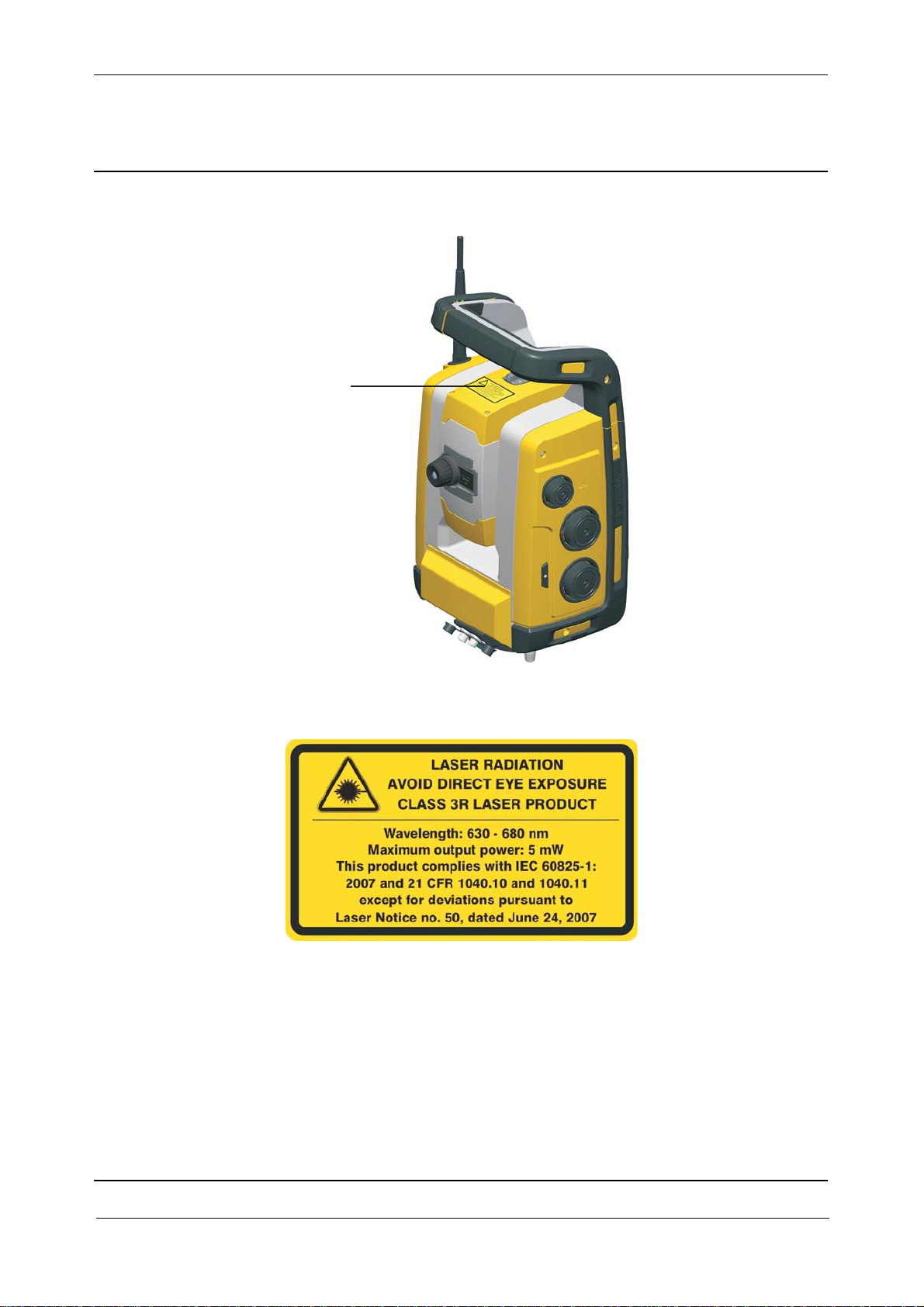
The Trimble S3 DR, RTS555 DR , RTS655 DR, SPS620 DR, SPS720 DR Total Stations are CLASS
3R LASER PRODUCT:
Fig. 1-2 Laser warning label
Fig. 1-3 Laser aperture label
Trimble S, VX, SPS & RTS Service Manual1 - 8 P/N 57150002, Revision 5.0
Page 19
Chapter 1
F
The instrument contains visible and invisible laser sources:
• A laser diode for distance measuring in DR mode and laser pointer function operating at 660
nm (visible light), with a beam divergence of 0.4 x 0.4 mrad and an output power of <5 mW,
while the emission is coaxial with the telescope. This mode operates in LASER CLASS 3R.
• The laser diode for distance measuring in prism mode operates at 660 nm (visible light), with
a beam divergence of 0.4 x 0.4 mrad and an output power of <0.017 mW, while the emission is
coaxial with the telescope. This mode operates in LASER CLASS 1.
• An Autolock laser diode operates at 785 nm (infrared, non-visible light), with a beam
divergence of 38.5 mrad and an output power of < 0.35 mW, while the emission is coaxial with
the telescope. This mode operates in LASER CLASS 1.
Laser and LED Information Trimble S3 DR / RTS555 DR / RTS655 DR / SPS620 DR / SPS720 DR
The Trimble S3 DR, RTS555 DR, RTS 655 DR, SPS620 DR, SPS720 DR Total Stations have been
tested, and complies with the regulations for Class 3R Laser products
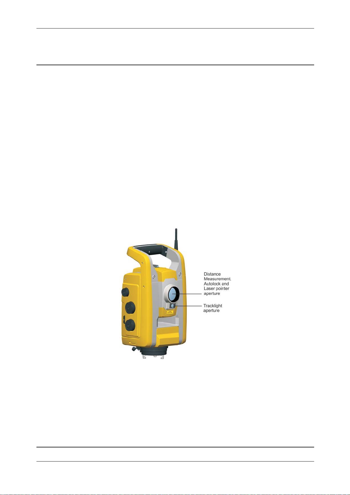
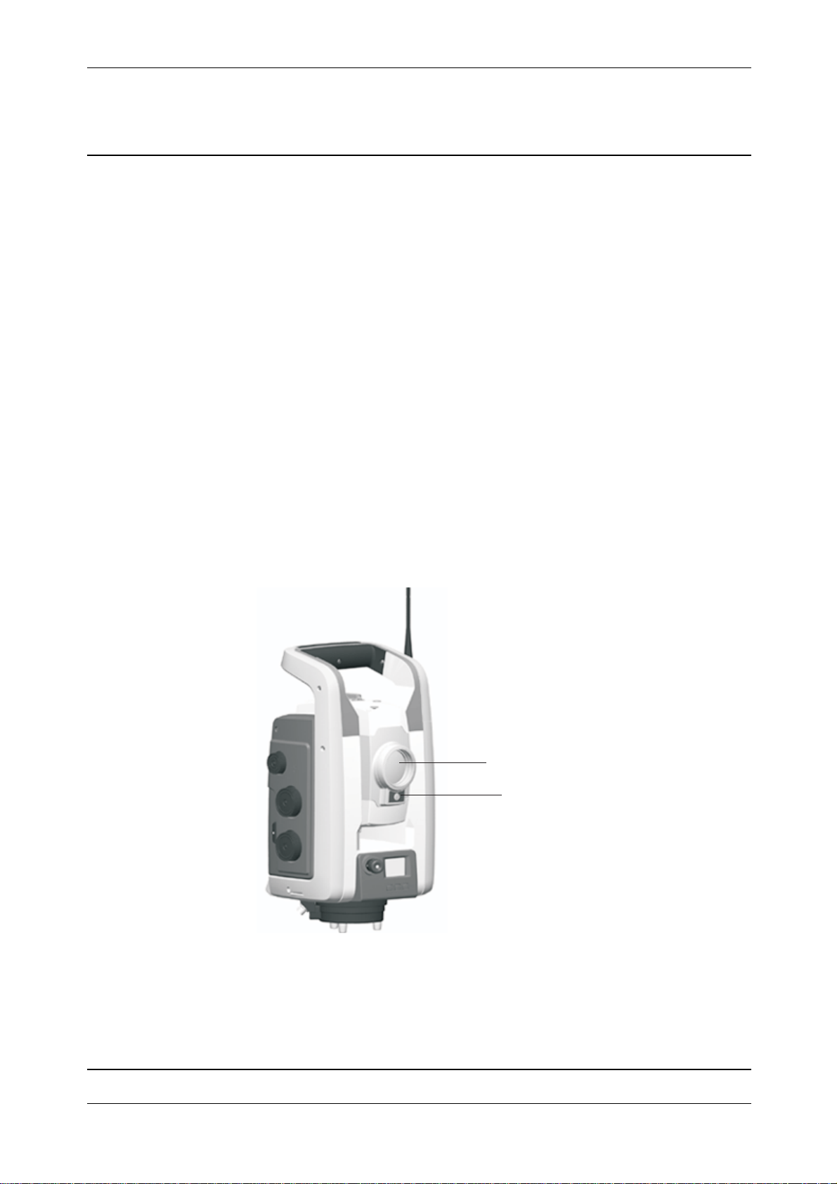
Fig. 1-4 Trimble S3 DR Total Station apertures
General Information and safety
P/N 57150002, Revision 5.0 1 - 9 Trimble S, VX, SPS & RTS Service Manual
Page 20
Chapter 1
F
Fig. 1-5 Trimble RTS555 DR / RTS655 DR Total Station apertures
General Information and safety
Distance
measurement
Autolock and
laser pointer
aperture
Tracklight aper ture
Fig. 1-6 Trimble SPS620 DR / SPS720 DR Total Station apertures
Distance
measurement
tracker and
laser pointer
aperture
Tracklight
aperture
Trimble S, VX, SPS & RTS Service Manual1 - 10 P/N 57150002, Revision 5.0
Page 21
Chapter 1
F
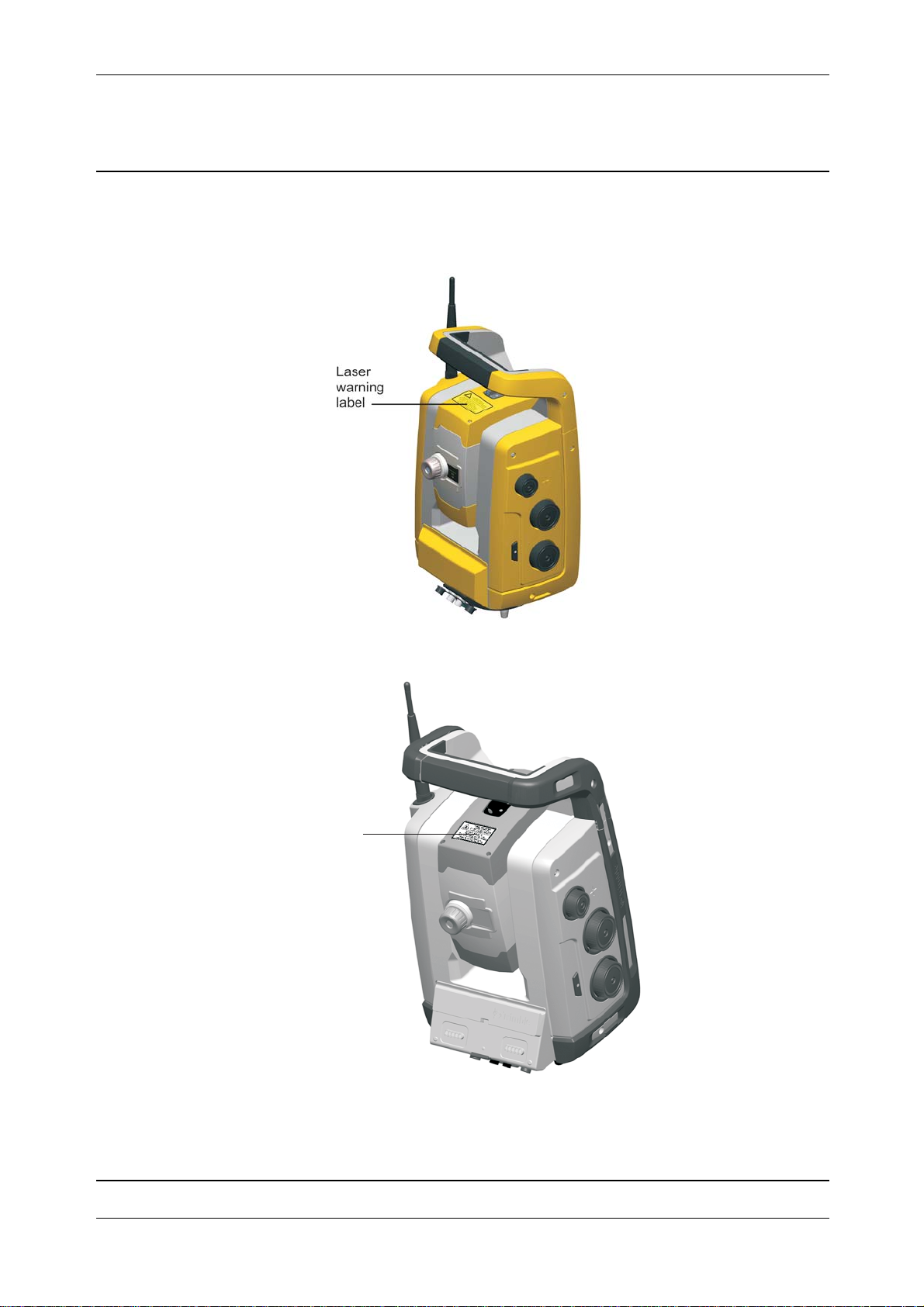
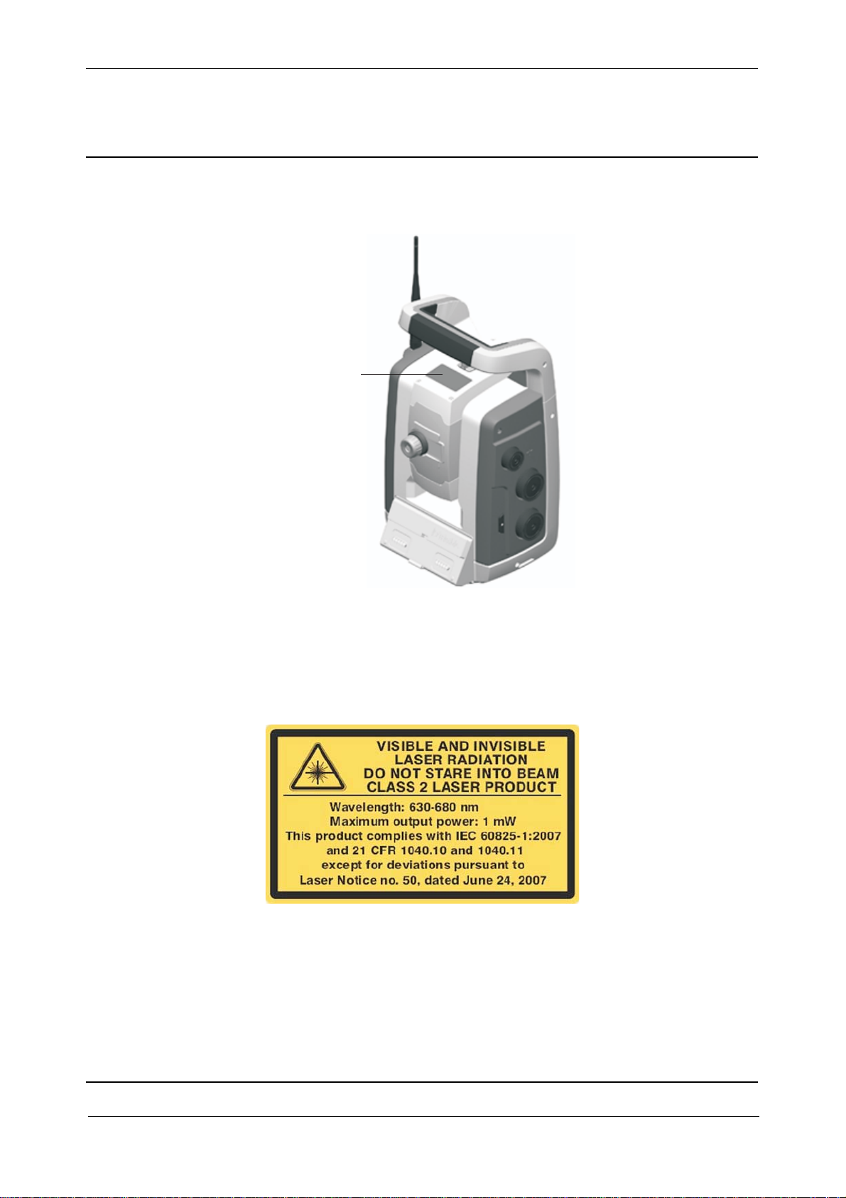
The laser warning label is located on top of the distance measuring unit.
Fig. 1-7 Location of laser warning label on a Trimble S3 DR Total Station
General Information and safety
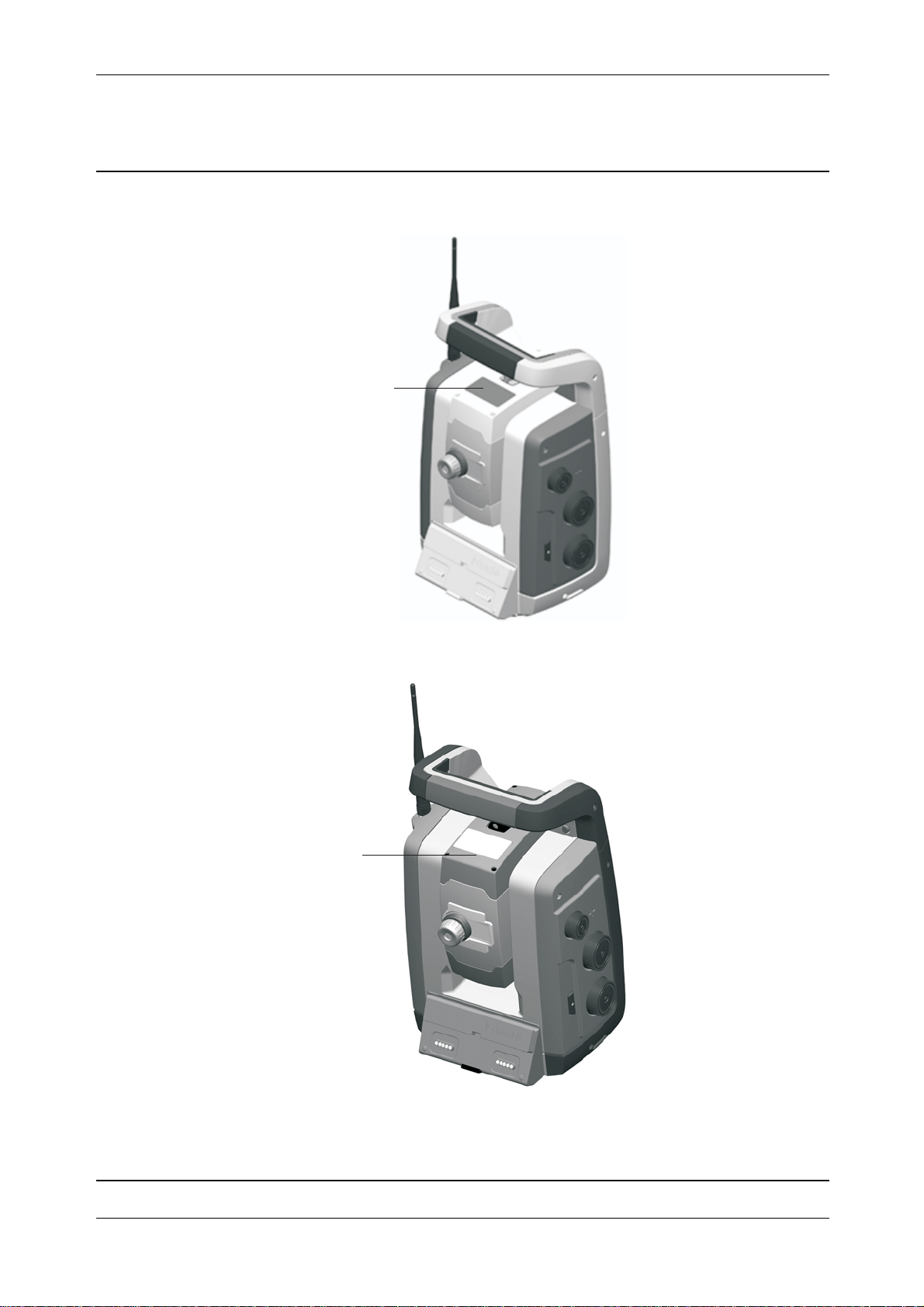
Fig. 1-8 Location of laser warning label on a Trimble RTS555 DR / RTS655 DR Total Station
aser
arning label
P/N 57150002, Revision 5.0 1 - 11 Trimble S, VX, SPS & RTS Service Manual
Page 22
Chapter 1
F
Fig. 1-9 Location of laser warning label on a Trimble SPS620 DR / SPS720 DR Total Station
Laser
Warning
Label
General Information and safety
Fig. 1-10 Laser warning label Trimble S3 DR / RTS555 DR / RTS655 DR / SPS620 DR / SPS720 DR
Total Station
Trimble S, VX, SPS & RTS Service Manual1 - 12 P/N 57150002, Revision 5.0
Page 23
Chapter 1
F
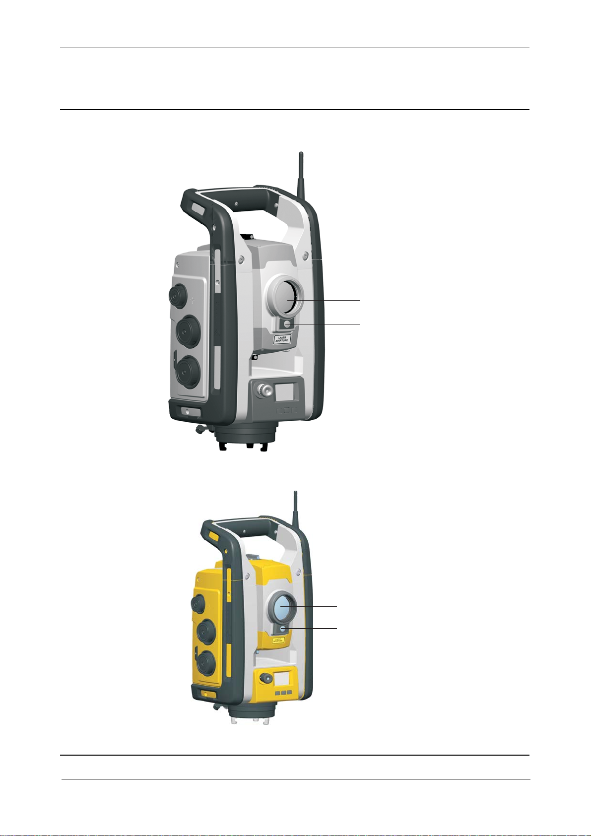
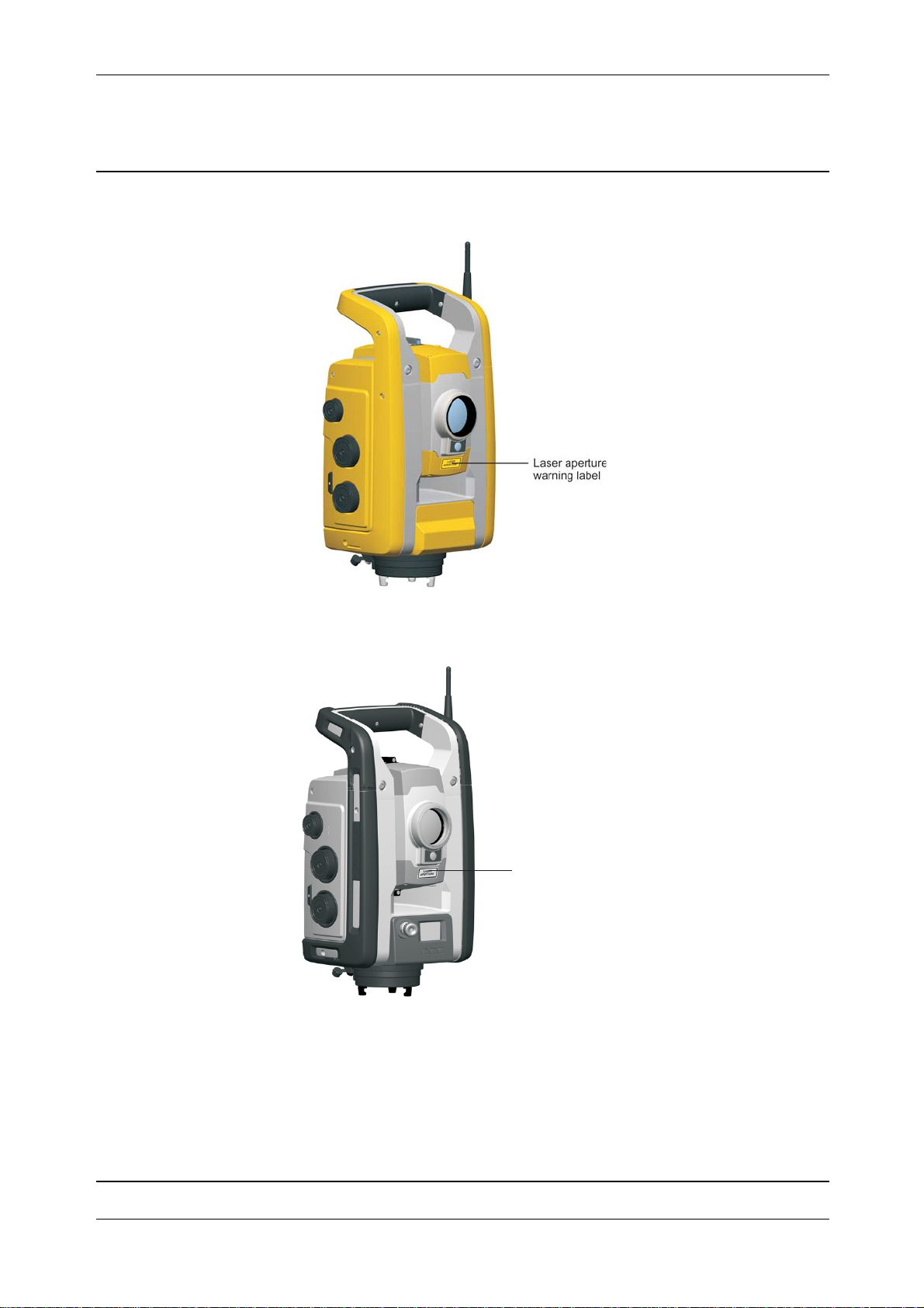
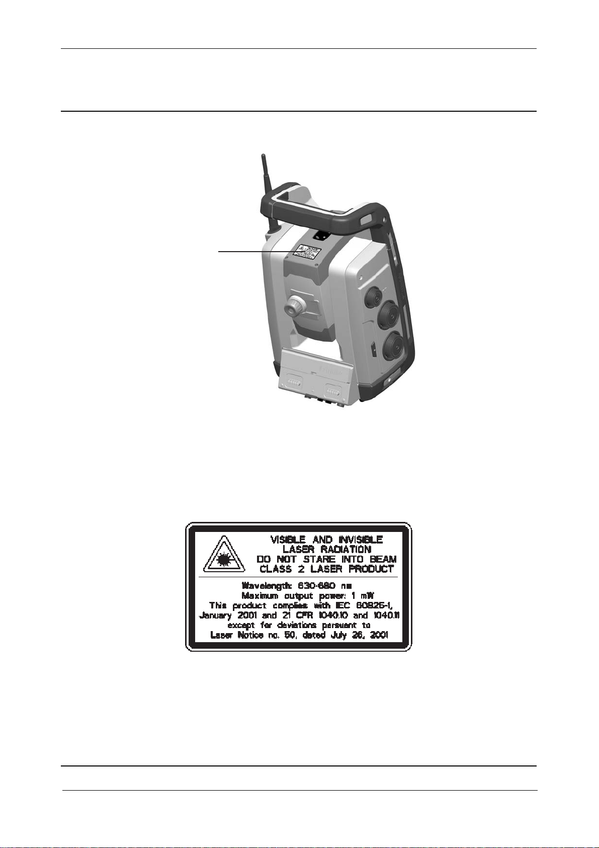
Fig. 1-11 Location of laser aperture warning label on a Trimble S3 DR Total Station
General Information and safety
Fig. 1-12 Location of laser aperture warning label on a Trimble RTS555 DR / RTS655 DR Total Station
aser aperture
arning label
P/N 57150002, Revision 5.0 1 - 13 Trimble S, VX, SPS & RTS Service Manual
Page 24
Chapter 1
F
Fig. 1-13 Location of laser aperture warning label on a Trimble SPS620 DR / SPS720 DR Total Station
General Information and safety
Laser aperture
warning label
Fig. 1-14 Laser aperture warning label Trimble S3 DR / RTS555 DR / RTS 655 DR / SPS620 DR /
SPS720 DR Total Station
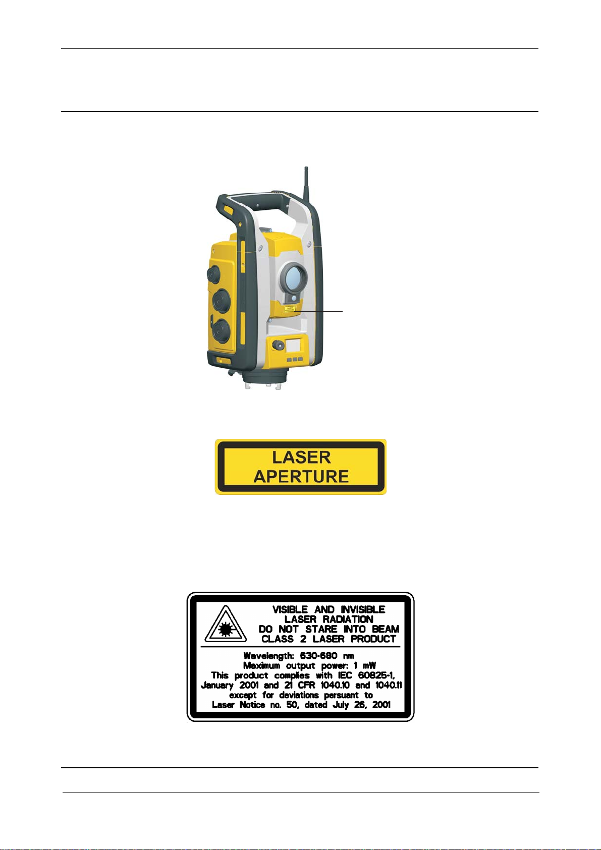
Trimble S6 DR300+ (and Optional Autolock®) / VX / SPS DR300+ / RTS DR300+
The Trimble S6 DR300+ (with Autolock®), VX, SPS DR300+ and RTS DR300+ is a CLASS 2
LASER PRODUCT
Fig. 1-15 Laser pointer warning label
Trimble S, VX, SPS & RTS Service Manual1 - 14 P/N 57150002, Revision 5.0
Page 25
Chapter 1
F
The instrument contains visible and invisible laser sources:
• A laser diode for the distance measuring function operating at 870 nm (infrared, non-visible
light), with a beam divergence of 0.40.8 mrad and an output power of <0.48 mW, laser
CLASS 1.
• A laser diode for laser pointer function operating at 630 - 680 nm (visible light), with a beam
divergence of 0.3 mrad and an output power of < 0.8 mW, while the emission is coaxial with
the telescope. This mode operates in LASER CLASS 2.
• The laser diode for distance measuring in prism and DR mode operates at 870 nm (infrared,
non-visible light), with a beam divergence of 0.40.8 mrad and an output power of <0,48 mW.
This mode operates in LASER CLASS 1.
• As an option, an Autolock laser diode operates at 785 nm (infrared, non-visible light), with a
beam divergence of 38.5 mrad and an out put power of <0.35 mW, while the emission is coaxial
with the telescope. This mode operates in LASER CLASS 1.
When operating in prism mode with Autolock and/or distance measurement the accessible radiation
does not exceed the limits of LASER CLASS 1.
Laser and LED Information Trimble S6 DR300+ / VX / SPS DR300+ / RTS DR300+
General Information and safety
The Trimble S6 DR300+ (with Autolock®), VX, SPS DR300+ and RTS DR300+ has been tested and
complies with the regulations for a Class 1 and Class 2 Laser product.
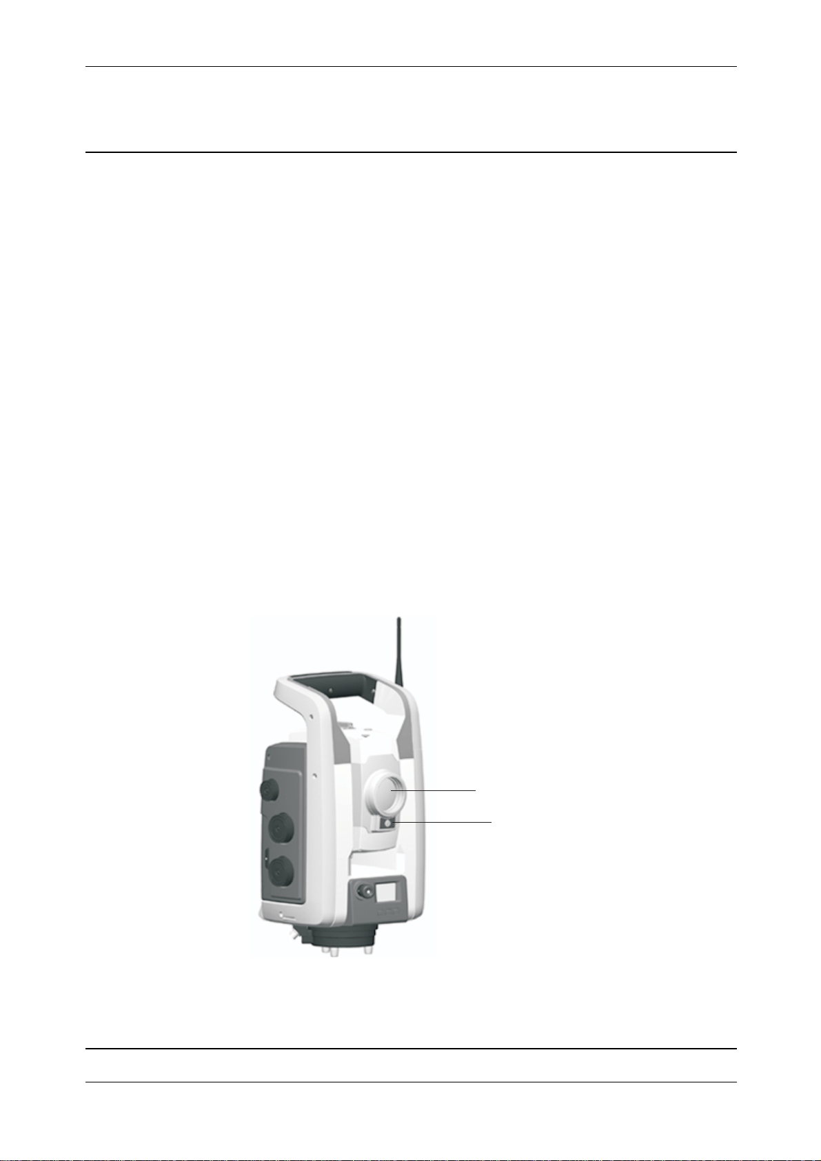
Fig. 1-16 Trimble S6 DR300+ / VX / SPS DR300+ / RTS 300+
Distance
measurement
Autolock and
Laser pointer
aperture
Tracklight®
aperture
The laser pointer warning label, see Fig. 1-15 on page 1-14 is located on top of the distance unit
cover.
P/N 57150002, Revision 5.0 1 - 15 Trimble S, VX, SPS & RTS Service Manual
Page 26
Chapter 1
F
Fig. 1-17 Location of laser pointer warning label on a Trimble S6 DR300+ / VX / SPS DR300+ / RTS
300+
Laser pointer
warning label
General Information and safety
Trimble S6 DR PLUS / S8 DR PLUS / VX DR PLUS / SPS DR PLUS / RTS DR PLUS
The Trimble S6 DR PLUS / S8 DR PLUS / VX DR PLUS/ SPS DR PLUS / RTS DR PLUS is a
CLASS 2 LASER PRODUCT
Fig. 1-18 Laser pointer warning label
Trimble S, VX, SPS & RTS Service Manual1 - 16 P/N 57150002, Revision 5.0
Page 27

Chapter 1
F
The instrument contains visible and invisible laser sources:
• A laser diode for the distance measuring function operating at 905 nm (infrared, non-visible
light), with a beam divergence of 0.4 x 0.8 mrad and an output power of <1.1 mW, LASER
CLASS 1.
• A laser diode for laser pointer function operating at 630 - 680 nm (visible light), with a beam
divergence of 0.3 mrad and an output power of <0.7 mW, while the emission is coaxial with the
telescope. This mode operates in LASER CLASS 2.
• As an option, an Autolock laser diode operates at 785 nm (infrared, non-visible light), with a
beam divergence of 38.5 mrad and an out put power of <0.35 mW, while the emission is coaxial
with the telescope. This mode operates in LASER CLASS 1.
When operating in prism mode with Autolock and/or distance measurement the accessible radiation
does not exceed the limits of LASER CLASS 1.
Laser and LED Information Trimble S6 DR PLUS / S8 DR PLUS / VX DR PLUS / SPS DR PLUS / RTS DR PLUS
The Trimble S6 DR PLUS / S8 DR PLUS / VX DR PLUS/ SPS DR PLUS/ RTS DR PLUS has been
tested and complies with the regulations for a Class 1 and Class 2 Laser product.
General Information and safety
Fig. 1-19 Trimble S6 DR PLUS
Distance
measurement
Autolock and
Laser pointer
aperture
Tracklight®
aperture
P/N 57150002, Revision 5.0 1 - 17 Trimble S, VX, SPS & RTS Service Manual
Page 28

Chapter 1
F
Fig. 1-20 Trimble S8 DR PLUS / VX DR PLUS
General Information and safety
Distance
measurement
tracker and
laser pointer
aperture
Camera aperture
Fig. 1-21 Trimble SPS DR PLUS / RTS DR PLUS
Distance
measurement
tracker and
laser pointer
aperture
Tracklight
aperture
The laser pointer warning label, see Fig. 1-18 on page 1-16 is located on top of the distance unit
cover.
Trimble S, VX, SPS & RTS Service Manual1 - 18 P/N 57150002, Revision 5.0
Page 29
Chapter 1
F
Fig. 1-22 Location of laser pointer warning label on a Trimble S6 DR PLUS
Laser pointer
warning label
General Information and safety
Fig. 1-23 Location of laser pointer warning label on a Trimble S8 DR PLUS/VX DR PLUS
aser
arning label
P/N 57150002, Revision 5.0 1 - 19 Trimble S, VX, SPS & RTS Service Manual
Page 30
Chapter 1
F
Fig. 1-24 Location of laser warning label on a Trimble SPS DR PLUS / RTS DR PLUS
Laser
Warning
Label
General Information and safety
Trimble S6 High Precision (and Optional Autolock®) / S8 High Precision / SPS DR Standard / RTS DR Standard
The Trimble S Series High Precision / DR Standard (with Autolock®) is a CLASS 2 LASER
PRODUCT:
Fig. 1-25 Laser pointer warning label
Trimble S, VX, SPS & RTS Service Manual1 - 20 P/N 57150002, Revision 5.0
Page 31
Chapter 1
F
The instrument contains visible and invisible laser sources:
• A laser diode for distance measuring in DR- mode and laser pointer function operating at 660
nm (visible light), with a beam divergence of 0.4 x 0.4 mrad and an output power of <1 mW,
while the emission is coaxial with the telescope. This mode operates in LASER CLASS 2.
• The laser diode for distance measuring in prism mode operates at 660 nm (visible light), with
a beam divergence of 0.4 x 0.4 mrad and an output power of <0,017 mW, while the emission is
coaxial with the telescope. This mode operates in LASER CLASS 1.
• As an option, an Autolock laser diode operates at 785 nm (infrared, non-visible light), with a
beam divergence of 38.5 mrad and an output power of < 0.35 mW, while the emission is coaxial
with the telescope. This mode operates in LASER CLASS1.
When operating in prism mode with Autolock and/or distance measurement the accessible radiation
does not exceed the limits of LASER CLASS 1.
Laser and LED Information Trimble S6 High Precision / S8 High Precision / SPS DR Standard / RTS DR Standard
The Trimble S Series High Precision / DR Standard has been tested and complies with the regulations
for a Class 2 Laser product.
General Information and safety
Fig. 1-26 Trimble S6 High Precision / S8 High Precision / SPS DR Standard / RTS DR Standard
Distance
measurement
Autolock and
Laser pointer
aperture
Tracklight®
aperture
The laser pointer warning label, see Figure 1-5 is located on top of the distance unit cover.
P/N 57150002, Revision 5.0 1 - 21 Trimble S, VX, SPS & RTS Service Manual
Page 32

Chapter 1
F
Fig. 1-27 Location of laser pointer warning label on a Trimble S6 High Precision / S8 High Precision
/ SPS DR Standard / RTS DR Standard
Laser pointer
warning label
General Information and safety
Trimble S8 Series High Precision with Long Range FineLock
The Trimble S8 Series High Precision with Long Range FineLock is a CLASS 2 LASER PRODUCT.
The instrument contains visible and invisible laser sources:
• A laser diode for distance measuring in DR- mode and laser pointer function operating at 660
nm (visible light), with a beam divergence of 0.4 x 0.4 mrad and an output power of <1 mW,
while the emission is coaxial with the telescope. This mode operates in LASER CLASS 2.
• The laser diode for distance measuring in prism mode operates at 660 nm (visible light), with
a beam divergence of 0.4 x 0.4 mrad and an output power of <0,017 mW, while the emission is
coaxial with the telescope. This mode operates in LASER CLASS 1.
• An Autolock laser diode operates at 785 nm (infrared, non-visible light), with a beam
divergence of 38.5 mrad and an output power of < 0.35 mW, while the emission is coaxial with
the telescope. This mode operates in LASER CLASS1.
• A Long Range FineLock laser diode operates at 785 nm (infrared, non-visible light), with a
beam divergence of 2,5 mrad and an output power of <0.35 mW, while the emission is biaxial
and eccentric with the telescope axis. This mode operates in LASER CLASS 1.
The Autolock laser diode and the Long Range FineLock laser diode can not operate at the same time.
When operating in prism mode with Autolock and/or distance measurement the accessible radiation
does not exceed the limits of LASER CLASS 1.
Trimble S, VX, SPS & RTS Service Manual1 - 22 P/N 57150002, Revision 5.0
Page 33

Chapter 1
F
Trimble S8 Series High Precision with High Power Laser Pointer
The Trimble S8 Series High Precision with High Power Laser Pointer is a CLASS 3 LASER
PRODUCT.
Fig. 1-28 High Power Laser pointer warning label
Fig. 1-29 High Power Laser pointer aperture label
General Information and safety
The instrument contains visible and invisible laser sources:
• A laser diode for distance measuring in DR- mode and laser pointer function operating at 660
nm (visible light), with a beam divergence of 0.4 x 0.4 mrad and an output power of <1 mW,
while the emission is coaxial with the telescope. This mode operates in LASER CLASS 2.
• The laser diode for distance measuring in prism mode operates at 660 nm (visible light), with
a beam divergence of 0.4 x 0.4 mrad and an output power of <0,017 mW, while the emission is
coaxial with the telescope. This mode operates in LASER CLASS 1.
• An Autolock laser diode operates at 785 nm (infrared, non-visible light), with a beam
divergence of 38.5 mrad and an output power of < 0.35 mW, while the emission is coaxial with
the telescope. This mode operates in LASER CLASS1.
• A laser pointer function operating at 660 nm (visible light), with a full beam divergence of 0,2
mrad (1/e^2) and an output power of <3,5 mW, while the emission is biaxial and eccentric to
the telescope. This mode operates in LASER CLASS 3R.
The laser for the high power laser pointer and the laser for measuring in DR mode may be run at the
same time. This mode is within LASER CLASS 3R.
P/N 57150002, Revision 5.0 1 - 23 Trimble S, VX, SPS & RTS Service Manual
Page 34

Chapter 1
F
Laser and LED Information Trimble S6 High Precision / S8 / SPS DR Standard / RTS DR Standard
The Trimble S Series High Precision / S8 / SPS DR Standard / RTS DR Standard has been tested and
complies with the regulations for a Class 2 Laser product.
The Trimble S8 High Precision with optional High Power Laser Pointer has been tested and complies
with the regulations for a Class 3R laser product.
Fig. 1-30 Trimble S6 High Precision / S8 / SPS DR Standard / RTS DR Standard
General Information and safety
Distance
measurement
Autolock and
Laser pointer
aperture
Tracklight®
aperture
Trimble S, VX, SPS & RTS Service Manual1 - 24 P/N 57150002, Revision 5.0
Page 35

Chapter 1
F
Fig. 1-31 Location of laser pointer warning label on a Trimble S6 High Precision / S8 / SPS DR
Standard / RTS DR Standard and High Power Laser pointer warning label on a Trimble S8.
Laser pointer
warning label
General Information and safety
Fig. 1-32 Laser pointer warning label
P/N 57150002, Revision 5.0 1 - 25 Trimble S, VX, SPS & RTS Service Manual
Page 36

Chapter 1
F
Fig. 1-33 High Power Laser pointer warning label
Fig. 1-34 Laser pointer warning label with optional High Power Laser Pointer
General Information and safety
Fig. 1-35 High Power Laser pointer aperture label
Trimble S, VX, SPS & RTS Service Manual1 - 26 P/N 57150002, Revision 5.0
Page 37

Chapter 1
F
Service procedure recommendations
Updating firmware during service / repair
It is recommended to upgrade the instruments firmware to latest version during service / repair. After
repair if necessary due to customer request (application software compatibility, see “Firmware
Compatibility” on page 3-54.) downgrade the instrument before running Final Test & Report in
PASS.
General Information and safety
P/N 57150002, Revision 5.0 1 - 27 Trimble S, VX, SPS & RTS Service Manual
Page 38
Chapter 1
F
General Information and safety
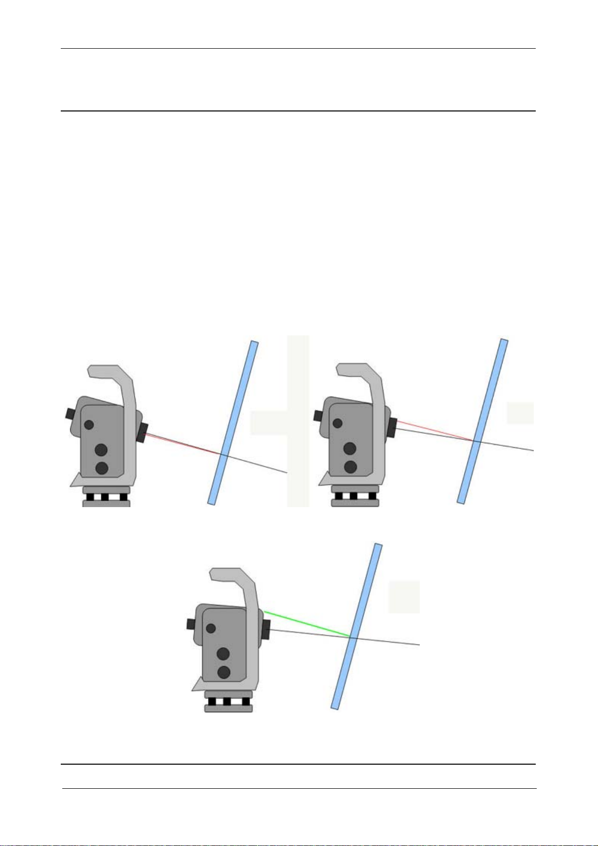
Measuring through glass window
Guidelines when measuring through glass windows
• A modern window glass should be fine. Avoid using tinted glass window.
• The range is reduced by 10-20% when measuring through a window.
• Depending on the window angle to the instrument the window can introduce back reflection
from the EDM to the instrument front lens. See fig below.
• The field of view through the glass window is limited horizontal by +/-60 deg and vertical by
+/-30 deg.
Window reflection from EDM
Use the laser pointer to verify the EDM reflex is outside the optical lens.
Fig. 1-36 Problem with reflection
Fig. 1-37 No problem with reflection
Trimble S, VX, SPS & RTS Service Manual1 - 28 P/N 57150002, Revision 5.0
Page 39

Chapter 2
F
General Product Information
2 General Product Information
Trimble S3 - Product description & Service Information
Trimble S6 - Product description & Service information
Trimble S8 - Product description & Service information
Trimble VX - Product description & Service information
Trimble RTS - Product description & Service information
Trimble SPS - Product description & Service information
Models and serial numbers
Instrument Model Matrix
Product Specifications
Model definition
P/N 57150002, Revision 5.0 2 - 1 Trimble S, VX, SPS & RTS Service Manual
Page 40

Chapter 2
F
General Product Information
Trimble S3 - Product description & Service Information
Product description
Trimble S3 Total Station — A Total Station with MagDrive™ Technology
The Trimble S3 Total Station is available as Servo, Autolock or Robotic. The S3 Total Station Servo
and Autolock has a fixed control panel. The Trimble S3 Total Station Robotic has no panel attachment and is used together with a hand held controller e.g. Trimble TSC2.
The Trimble® S3 Total Station is based on the Trimble® S6 Total Station
Differences to Trimble S6 Total Station
All models:
• DR EDM based on High Precision /DR Standard EDM
• MagDrive™ servo technology, 85 degrees per second (S6 115 degrees per second)
• Not upgradable
• No SurePoint
• No Face 2 display/panel (Face 2 display/panel available for some markets on Servo/Autolock
models)
• No pressure sensor
• Optical plummet in tribrach
• Yellow center unit and side covers
Servo/Autolock models:
• Fixed control panel
Robotic models:
• Radio range of 300m
• 10mW 2.4GHz radio
• No panel attachment
Service information
The Trimble S3 Total Station is adjusted and tested in the same procedure as the Trimble S6 Total
Station except for the differences described herein.
Trimble S, VX, SPS & RTS Service Manual2 - 2 P/N 57150002, Revision 5.0
Page 41

Chapter 2
F
General Product Information
Trimble S6 - Product description & Service information
Product description
Trimble S6 — A Servo, Autolock, or Robotic Total Station with MagDrive™ Technology
The Trimble® S6 DR (direct reflex) Total Station offers advanced MagDrive technology for breathtaking speed. It takes the work out of conventional servo or robotic surveying.
For your unsurpassed efficiency, the Trimble S6 is a 100% cable-free robotic total station and rover.
Numerous new features and the latest technologies will catapult your productivity and profitability
forward. And as an entirely upgradable surveying solution, the Trimble S6 will grow with your business.
Advanced MagDrive Technology
Fast. Silent. Precise. The Trimble S6 Total Station redefines these words with exceptional servo performance. The Trimble S6 is engineered with innovative MagDrive™ servo technology that silently
spins the instrument at just 115 degrees per second. For more detailed information, please download
the MagDrive Technology White Paper.
Trimble MultiTrack Target for Both Active and Passive Tracking
Choose from active or passive tracking with the Trimble MultiTrack™ Target, the only target of its
kind in the surveying industry. Active tracking ensures you always locate and lock on to the correct
target. When you're using the Trimble MultiTrack Target, nearby reflective surfaces, such as road
signs, cars, safety vests, and other prisms, will not disrupt your surveys.
Trimble GPS Search for Even Faster Measurements
If MagDrive and MultiTrack speed still aren't enough, the robotic Trimble S6 instrument goes to the
extreme with Trimble® GPS Search. A new function in Trimble field software, GPS Search employs
GPS to quickly locate a lost prism. In just 3 seconds the Trimble S6 can zip to the correct position
and lock onto the robotic rover. For more details, download the GPS Search white paper.
See Trimble S6 Total Station brochure on www.trimble.com for more information.
See White Paper about Direct reflex EDM technology on www.trimble.com for more technical infor-
mation.
See White Paper about MagDrive servo technology on www.trimble.com for more technical infor-
mation.
P/N 57150002, Revision 5.0 2 - 3 Trimble S, VX, SPS & RTS Service Manual
Page 42

Chapter 2
F
General Product Information
Trimble S8 - Product description & Service information
Product description
The Trimble® S8 Total Station is Trimble's most advanced Autolock and Robotic total station. It's
designed to deliver unsurpassed performance and productivity in land surveying and specialized
engineering applications, such as monitoring and tunnelling.
A Complete System For Engineering Applications
The Trimble S8 Total Station works with Trimble Survey Controller™ field software and Trimble®
4D Control™ processing software to provide a seamless connected, complete solution for engineering jobs.
• Angular accuracy of 0,5” or 1”
• High Precision EDM of 1 mm + 1 ppm or DR Plus EDM of 2 mm + 2 ppm
• Trimble® FineLock™ technology: FineLock technology is a smart tracker sensor with a
narrow field of view that enables the Trimble S8 to detect a target without interference from
surrounding prisms. This is especially useful in engineering applications such as monitoring
and tunnelling where multiple targets with very tight spacing are used.
• Trimble VISION™ on board the Trimble S8 enables users to control the instrument and to see
everything the instrument sees with live video on the controller.
• 10 Hz high-speed synchronized data output makes data collection faster and more accurate,
e.g., during railway monitoring a trolley or ATV, the prism can move more quickly without
compromising accuracy.
• Trimble eProtect™ security uses a 4-digit password to prevent access by unauthorized users.
Optional Features for Specialized Engineering Applications
1. The Long-Range FineLock™ configuration extends 1 cm precision to 2500 meters.
2. For tunnelling, a long-range laser pointer cuts through dusty conditions to provide precision
stakeout for bolts and other assets.
3. Trimble 4D Control™ is a comprehensive software solution designed for engineering
applications. Enabling both real-time and post processor applications, it allows users to
accurately characterize and interrogate data to determine movement over time.
4. The Engineering Option for Trimble Survey Controller expedites data collection for
monitoring applications and leads you through tasks such as marking areas of under and
overcut with the laser pointer.
Difference to Trimble S6
• Trimble FineLock and optional Long-Range FineLock™, see above.
• Optional High Power Laser Pointer (3R laser pointer).
• Tracklight module is replaced by Tracker Long Range or High Power Laser Pointer module.
• 10 Hz high-speed synchronized data output.
• PIN/PUK code security, see “Trimble eProtectTM - PIN/PUK code security” on page 3-59.
• Instrument Remote control, connecting a special cable (53094001) to the instrument makes it
possible to switch the instrument between ON and STANDBY modes via cable/radio
connection.
Trimble S, VX, SPS & RTS Service Manual2 - 4 P/N 57150002, Revision 5.0
Page 43

Chapter 2
F
Service information
The tracker is adjusted and tested in the same procedure as the Trimble S6.
Check Monitoring option is available in face2 display at start up.
General Product Information
P/N 57150002, Revision 5.0 2 - 5 Trimble S, VX, SPS & RTS Service Manual
Page 44

Chapter 2
F
General Product Information
Trimble VX - Product description & Service information
Product description
Trimble VX Spatial Station can be ordered with or without the scanning option (model code 936).
This option can later be installed in the instrument.
Designed to capture shapes, details, and coordinates, the Trimble VX offers an easy entry into Spatial
Imaging. The instrument is optimized for the acquisition of information using integrated video, scanning and positioning technologies. The Trimble VX Spatial Station is the ideal solution for combining
standard resolution 3D scans and digital imaging with survey-precise coordinate measurements and
2D deliverables:
• Intuitive video overlay provides visual cues on screen to speed data collection
• Spinning 115 degrees per second, MagDrive™ servo movement ensures fast, efficient
measuring.
• Trimble VISION technology, enhances data deliverables with images captured at the jobsite.
• Trimble VX measurements can be complemented with GNSS positioning for more flexibility
in the field.
The Trimble® VX™ Spatial Station for Spatial Imaging integrates state-of-the-art optical, 3D scanning, and digital imaging technology to capture the shape, detail and precise coordinates of any job.
The resulting 2D and 3D enhanced deliverables will satisfy colleagues and clients alike.
Difference to Trimble S6
• Tracklight module replaced by video camera module
• PIN/PUK code security, see “Trimble eProtectTM - PIN/PUK code security” on page 3-59.
Service information
Video camera is focused and calibrated in the instrument.
Trimble S, VX, SPS & RTS Service Manual2 - 6 P/N 57150002, Revision 5.0
Page 45

Chapter 2
F
General Product Information
Trimble RTS - Product description & Service information
Trimble RTS is a product line for the Layout segment within Construction division.
Product description
Trimble RTS555 DR Standard Total Station - WLAN
The Trimble RTS555 DR Standard utilizes 802.11 Wireless Local Area Network (WLAN) technology to create a wireless link between the controller and robotic total station to increase layout convenience and productivity in the field. The wireless solution reduces the number of components
needed, such as the external radio, battery and cable when used with the wireless Trimble LM80 Layout Manager, minimizing the weight and complexity of the system while providing a more ergonomic
and convenient layout solution.
The RTS555 DR Standard includes a WLAN radio in the instrument instead of a 2.4 Radio in the
instrument. This instrument can communicate to a Nomad controller also including a WLAN radio
running application software LM80.
Trimble RTS633 DR 300+ Total Station
Replaces Trimble SPS710 DR300+ Total Station.
Trimble RTS655 DR Standard Total Station
Replaces Trimble SPS610 DR Standard Total Station.
Difference to Trimble S6
• Different style with rugged side covers (same as SPS).
• RTS555 includes a WLAN radio
Service information
WLAN radio is configured in the face 2 panel and not in PASS.
P/N 57150002, Revision 5.0 2 - 7 Trimble S, VX, SPS & RTS Service Manual
Page 46

Chapter 2
F
General Product Information
Trimble SPS - Product description & Service information
Trimble SPS is a product line for the Heavy & Highway segment within Construction division.
Product description
Trimble SPSx20 Robotic Total Station
The SPS620 and SPS720 Robotic Total Stations offer a cost-effective solution for construction site
measurement and stakeout operations in Servo, Autolock, or Robotic mode. Both models provide a
robotic operating range of 500 meters, making them ideal for smaller site operations and work on
structures such as bridges or culverts.
The SPS620 and SPS720 use the Trimble DR short-range reflectorless EDM technology for singleshot measurements and operate with TSC2® or Trimble Tablet running the SCS900 Site Controller
Software. The SPS620 provides 5 arc second accuracy in the vertical and horizontal angles. The
SPS720 provides 3 arc second accuracy in the horizontal angle and 2 arc second accuracy in the vertical, and is well suited to more accurate site positioning work.
Trimble SPSx30 Universal Total Stations
Trimble SPS630, SPS730, and SPS930 Universal Total Stations can be ordered with or without the
machine control option (model codes 721/722/723) and OEM option. These options can later be
installed in the instrument.
Trimble SPS630 Universal Total Stations
Trimble SPS630 5” instrument satisfies all site measurement, stakeout, reflectorless measurement,
and grade control needs from a single instrument. Target customers are contractors performing their
own stakeout and site measurement tasks, who may also be somewhat price sensitive.
Applications
• Smaller operations where most of the work is performed close to the instrument
• In partnership with the GCS900-UTS-based system for excavators this system is typically used
on small sites where the machine operates close to the instrument
• Mining and quarry operations, where an instrument is needed for scanning quarry walls or
stockpiles of material
Trimble SPS730 and SPS930 Universal Total Stations
The SPS730 and SPS930 have been designed to operate as a universal total station. The instruments
have a machine control mode that optimizes the angle and distance measurement system through a
synchronization process that also reduces latency (age) of the data. In addition the instruments when
in machine control mode will output data at a higher rate than conventional total stations (20Hz). The
instrument radio system is designed to reduce jitter significantly, the instrument tracking and search
functions are optimized for dynamic tracking applications, and the instrument also features trajectory
prediction helping reacquire lock after the prism is obscured.
When operated in Site Positioning modes (SCS900 Standing, Walking and Vehicle modes) the instrument will also utilize the high update rates and synchronized data, however the radio master is at the
Trimble S, VX, SPS & RTS Service Manual2 - 8 P/N 57150002, Revision 5.0
Page 47

Chapter 2
F
instrument allowing for a one to one operation with the robotic rod controller. When operated in
Machine Control mode, the radio master shifts to the machine control box, so that it can control up
to five instruments on the same radio channel and network. In this mode the radio system is also optimized to eliminate jitter, which provides enhanced positioning control for the machine system
hydraulics.
When used for any machine control application, the instrument should be setup first with the SCS900
software, a station establishment carried out and then perform the shut down process and place the
instrument in Machine Control mode. This process involves placing the station establishment information in the instrument memory, so that it can be transferred to the calling machine control application.
The instrument capability to track moving vehicles and machines is referred to as Advanced Tracking
Sensor (ATS).
ATS capability delivers the following performance benefits for dynamic positioning applications
• Low, fixed and well defined latency of data output from the instrument and over the radio
• Synchronized angle and distance measurements
• 20Hz data update rates
General Product Information
• 16 Channel Target ID - 1-8 for Site Positioning mode and 9-16 for Machine Control mode.
• Optimized search routines designed for tracking a machine with trajectory prediction.
• Radio scanning capability, instrument can be programmed to sequentially scan a series of radio
channel and network ID combinations, allowing it to serve a number of machines, all on
different channels at a single location on demand.
• Radio network capability allowing up to 5 instruments to be operated from a single machine on
the same channel and network ID
Difference to Trimble S6
• Different style with rugged side covers, (same as RTS).
• Second configuration number to activate Site Positioning / Advanced Tracking Sensor (ATS)
function.
Service information
Check Machine Control option / OEM option are available in face2 display at start up.
Trimble SPS620 and SPS720 uses M firmware
Trimble SPS630, SPS730 and SPS930 uses C firmware
P/N 57150002, Revision 5.0 2 - 9 Trimble S, VX, SPS & RTS Service Manual
Page 48

Chapter 2
F
General Product Information
Models and serial numbers
Trimble S3 DR
Trimble model Model code Serial number
Trimble S3 2” DR / 2mm+2ppm (Servo) 910 91010001
Trimble S3 5” DR / 2mm+2ppm (Servo) 911 91110001
Trimble S3 2” DR / 2mm+2ppm (Autolock) 912 91210001
Trimble S3 5” DR / 2mm+2ppm (Autolock) 913 91310001
Trimble S3 2” DR / 2mm+2ppm (Robotic) 914 91410001
Trimble S3 5” DR / 2mm+2ppm (Robotic) 915 91510001
Trimble S3 2” DR / 2mm+2ppm (Servo) with Face2 display* 916 91610001
Trimble S3 2” DR / 2mm+2ppm (Autolock) with Face2 display* 917 91710001
* Models only available on some markets
Trimble S6 DR300+
Trimble model Model code Serial number
Trimble S6 2” DR300+ / 3mm+2ppm 926 92610001
Trimble S6 3” DR300+ / 3mm+2ppm 927 92710001
Trimble S6 5” DR300+ / 3mm+2ppm 928 92810001
Trimble S6 DR PLUS
Trimble model Model code Serial number
Trimble S6 2” DR PLUS/ 2mm+2ppm 930 93010001
Trimble S6 3” DR PLUS/ 2mm+2ppm 931 93110001
Trimble S6 5” DR PLUS/ 2mm+2ppm 932 93210001
Trimble S6 High Precision EDM with DR
Trimble model Model code Serial number
Trimble S6 1” High Precision / 1mm+1ppm 921 92110001
Trimble S8 High Precision
Trimble model Model code Serial number
Trimble S8 DR STD/1mm+1ppm/0,5" 988 98810001
Trimble S8 High Precision
- With FineLock option as standard
Trimble model Model code Serial number
Trimble S8 1" High Precision / 1mm+1ppm 980 98010001
Trimble S, VX, SPS & RTS Service Manual2 - 10 P/N 57150002, Revision 5.0
Page 49

Chapter 2
F
Trimble S8 High Precision
- Without FineLock option as standard
- Optional Long Range FineLock
- Optional High Power Laser Pointer
Trimble model Model code Serial number
Trimble S8 1” High Precision / 1mm+1ppm 981 98110001
Trimble S8 High Precision Railway
Trimble model Model code Serial number
Trimble S8 1” High Precision / 1mm+1ppm 982 98210001
Trimble S8 0.5” High Precision / 1mm+1ppm 983 98310001
Trimble S8 DR PLUS
Trimble model Model code Serial number
Trimble S8 2” DR PLUS/ 2mm+2ppm 990 99010001
Trimble S8 High Precision with camera
General Product Information
Trimble model Model code Serial number
Trimble S8 1” High Precision / 1mm+1ppm 989 98910001
Trimble S8 0.5” High Precision / 1mm+1ppm 991 99110001
Trimble S8 DR PLUS
- With FineLock option as standard
Trimble model Model code Serial number
Trimble S8 1" DR PLUS/ 2mm+2ppm 992 99210001
Trimble VX - With Scanning as standard option
Trimble model Model code Serial number
Trimble VX 1” DR 300+ / 3mm+2ppm 935 93510001
Trimble VX - Without Scanning as standard option
Trimble model Model code Serial number
Trimble VX 1” DR 300+ / 3mm+2ppm 936 93610001
Trimble VX
Trimble model Model code Serial number
Trimble VX 1” DR PLUS/ 2mm+2ppm 937 93710001
Trimble RTS Total Station - Building Construction
Model Model code Serial number
Trimble RTS555 5"/5" DR Standard / 2mm+2ppm 730 73010001
P/N 57150002, Revision 5.0 2 - 11 Trimble S, VX, SPS & RTS Service Manual
Page 50

Chapter 2
F
Model Model code Serial number
Trimble RTS633 3"/2" DR 300+ / 3mm+2ppm 731 73110001
Trimble RTS655 5"/5" DR Standard / 2mm+2ppm 732 73210001
Trimble RTS633 3"/2" DR PLUS / 2mm+2ppm 733 73310001
Trimble RTS555 5"/5" DR / 2mm+2ppm 734 73410001
Trimble RTS655 5"/5" DR / 2mm+2ppm 735 73510001
Trimble SPS Total Station - Building Construction / Heavy & Highway
Model Model code Serial number
Trimble SPS700 5"/2" DR 300+ / 3mm+2ppm 712 71210001
Trimble SPS610 5"/5" DR Standard / 2mm+2ppm 713 / 717 71320001
Trimble SPS710 3"/2" DR 300+ / 3mm+2ppm 718 71810001
Trimble SPS620 5"/5" DR / 2mm+2ppm 727 72710001
Trimble SPS720 3"/2" DR / 2mm+2ppm 728 72810001
Trimble SPS Total Station - Heavy & Highway
- With Machine Control option as standard
General Product Information
Model Model code Serial number
Trimble SPS730 3"/2" DR 300+ / 3mm+2ppm 714 71420001
Trimble SPS930 1"/1" DR 300+ / 3mm+2ppm 715 71520001
Trimble SPS Total Station - Heavy & Highway
- Without Machine Control option as standard
Model Model code Serial number
Trimble SPS630 5"/5" DR 300+ / 3mm+2ppm 721 72110001
Trimble SPS730 3"/2" DR 300+ / 3mm+2ppm 722 72210001
Trimble SPS930 1"/1" DR 300+ / 3mm+2ppm 723 72310001
Trimble SPS630 5"/5" DR PLUS / 2mm+2ppm 724 72410001
Trimble SPS730 3"/2" DR PLUS / 2mm+2ppm 725 72510001
Trimble SPS930 1"/1" DR PLUS / 2mm+2ppm 726 72610001
Trimble S3 model information
Trimble S3 is available as Servo, Autolock or Robotic. the instruments are not upgradable.
Trimble S6 model information
Trimble S6 is available in Servo, Autolock or Robotic configurations.
Trimble S, VX, SPS & RTS Service Manual2 - 12 P/N 57150002, Revision 5.0
Page 51

Chapter 2
F
General Product Information
Trimble S8 model information
Trimble S8 is available in Servo, Autolock or Robotic configurations.
Trimble VX model information
Trimble VX is only available in Robotic configuration.
Trimble RTS model information
Trimble RTS555 DR / DR Standard - WLAN available in Robotic configuration.
Trimble RTS655 DR / DR Standard - 2.4 Radio available in Robotic configuration.
Trimble RTS633 DR 300+ / DR PLUS available in Robotic configuration.
Trimble SPS model information
Trimble SPS610 DR Standard available in Autolock or Robotic configurations
Trimble SPS620 DR available in Robotic configuration.
Trimble SPS720 DR available in Robotic configuration.
Trimble SPS710 DR 300+ available in Robotic configuration.
Trimble SPS730 DR 300+ available in Autolock or Robotic configurations.
Trimble SPS930 DR 300+ available in Autolock or Robotic configurations.
Trimble SPS630 DR PLUS available in Autolock or Robotic configurations.
Trimble SPS730 DR PLUS available in Autolock or Robotic configurations.
Trimble SPS930 DR PLUS available in Autolock or Robotic configurations.
P/N 57150002, Revision 5.0 2 - 13 Trimble S, VX, SPS & RTS Service Manual
Page 52

Chapter 2
F
General Product Information
Instrument Model Matrix
The table below is a summary of existing Trimble S3/S6/S8/ VX / SPS and RTS released instruments.
Model matrix
Model Model
code
S3 DR 910 2” No 2010 Active -
S3 DR 911 5” No 2010 Active -
S3 DR 912 2” No 2010 Active -
S3 DR 913 5” No 2010 Active -
S3 DR 914 2” No 2009 Active -
S3 DR 915 5” No 2009 Active -
S3 DR 916 2” No 2010 Active -
S3 DR 917 2” No 2010 Active -
S6 DR300+ 926 2” No 2005 Obsolete since 2010 S6 DR
Angle
Accuracy
HTU
unit
Introduced Status Replaced by
model
PLUS
S6 DR300+ 927 3” No 2005 Obsolete since 2010 S6 DR
PLUS
S6 DR300+ 928 5” No 2005 Obsolete since 2010 S6 DR
PLUS
S6 HP 921 1” Yes 2006 Obsolete since 2008 S8
S6 DR PLUS 930 2” No 2010 Active -
S6 DR PLUS 931 3” No 2010 Active -
S6 DR PLUS 932 5” No 2010 Active -
S8 HP 988 0,5” Yes 2010 Active -
S8 HP 980 1” Yes 2007 Obsolete since 2008 S8 (981)
S8 HP 981 1” Yes 2008 Active -
S8 HP 982 1” Yes 2010 Active -
S8 HP 983 0,5” Yes 2010 Active -
S8 HP 989 1” Yes 2010 Active -
S8 DR PLUS 990 2” No 2010 Active -
S8 HP 991 0.5” Yes 2010 Active -
S8 DR PLUS 992 1” Yes 2011 Active -
VX 935 1” Yes 2007 Obsolete since 2008 VX (936)
VX 936 1” Yes 2008 Obsolete since 2010 VX DR
PLUS
Trimble S, VX, SPS & RTS Service Manual2 - 14 P/N 57150002, Revision 5.0
Page 53

Chapter 2
F
Model Model
code
VX DR
PLUS
SPS700 712 5"/2" No 2006 Obsolete since 2007 -
SPS610 713/
SPS710 718 3"/2" No 2007 Obsolete since 2009 SPS730 /
RTS555 730 5"/5" No 2009 Obsolete since 2010 RTS555 DR
RTS633 731 3"/2" No 2009 Obsolete since 2010 RTS633 DR
RTS633 733 3"/2" No 2010 Active -
RTS655 732 5"/5" No 2009 Obsolete since 2010 RTS655 DR
RTS555 DR 734 5"/5" No 2010 Active -
RTS655 DR 735 5"/5" No 2010 Active -
937 1” Yes 2010 Active -
717
Angle
Accuracy
5"/5" No 2007 Obsolete since 2009 SPS630 /
HTU
unit
General Product Information
Introduced Status Replaced by
model
RTS655
RTS633
PLUS
SPS730 714 3"/2" No 2007 Obsolete since 2009 SPS730
(722)
SPS930 715 1"/1" Yes 2007 Obsolete since 2009 SPS930
(723)
SPS630 721 5"/5" No 2009 Obsolete since 2010 SPS630
(724)
SPS730 722 3"/2" No 2009 Obsolete since 2010 SPS730
(725)
SPS930 723 1"/1" Yes 2009 Obsolete since 2010 SPS930
(726)
SPS630 724 5"/5" No 2010 Active -
SPS730 725 3"/2" No 2010 Active -
SPS930 726 1"/1" Yes 2010 Active -
SPS620 727 5"/5" No 2010 Active -
SPS720 728 3"/2" No 2010 Active -
P/N 57150002, Revision 5.0 2 - 15 Trimble S, VX, SPS & RTS Service Manual
Page 54

Chapter 2
F
Product Specifications
See Datasheet for each model on www.trimble.com for information.
General Product Information
Trimble S, VX, SPS & RTS Service Manual2 - 16 P/N 57150002, Revision 5.0
Page 55

Chapter 2
F
General Product Information
Model definition
The Trimble S3/ S6/S8/VX/SPS/RTS instruments has different functions and specifications but from
a service point the instrument has many common service operations.
The alidade is the base for all instruments, same as for Trimble S3/S6/S8/VX/SPS and RTS.
The centre unit can differs between models.
Centre unit- Distance unit
The Trimble S6 High Precision / Trimble S8 / Trimble RTS 555 DR Standard / Trimble RTS 655 DR
Standard and Trimble SPS610 DR Standard distance units has different specifications but uses the
same hardware and same service operations.
P/N 57150002, Revision 5.0 2 - 17 Trimble S, VX, SPS & RTS Service Manual
Page 56

Chapter 2
F
General Product Information
Trimble S, VX, SPS & RTS Service Manual2 - 18 P/N 57150002, Revision 5.0
Page 57

Chapter 3
F
3 Theory of Operation
Instrument
Removable handle
Battery / radio side cover
Radio unit
Servo side cover
IPC board
TCU attachment
TCU attachment with USB
Control Panel
Face2 panel & optical plummet
Pressure sensor
Servo drive system
Theory of Operation
Angle Measuring System
Base unit
PSM board
Tilt sensor
Software / Instrument application firmware
Telescope
Distance unit - DR300+ / DR PLUS
Distance unit - High Precision / DR Standard / DR
Tracker system
Tracklight
Servo focus
Video camera (Trimble S8 / VX)
Auto focus
Tracker Long Range - TLR
High Power Laser Pointer - HPL
Service interval
Board definitions
P/N 57150002, Revision 5.0 3 - 1 Trimble S, VX, SPS & RTS Service Manual
Page 58

Chapter 3
F
Instrument
Fig. 3-1 Base instrument parts
Battery &
Radio side
covers
Theory of Operation
Handle
Centre unit
Vertical angle unit
& servo motor
TCU attachment
Horizontal angle unit
& servo motor
Accelerometers
Face 2 panel
Tilt sensor
PSM board
Base unit
Optical plummet
IPC board
Servo side
cover
Trimble S, VX, SPS & RTS Service Manual3 - 2 P/N 57150002, Revision 5.0
Page 59

Chapter 3
F
Fig. 3-2 DR300+ / DR PLUS parts
Receiver board
Theory of Operation
Laser pointer
Greywedge motor assembly
Reticle illumination
Transmitter board
P/N 57150002, Revision 5.0 3 - 3 Trimble S, VX, SPS & RTS Service Manual
Page 60

Chapter 3
F
Fig. 3-3 EDM High Precision / DR Standard parts / DR
Transceiver board
Reference fibre
Theory of Operation
Transmitter unit
Greywedge motor
Switch motor
Receiver fibre
EDM frame
Trimble S, VX, SPS & RTS Service Manual3 - 4 P/N 57150002, Revision 5.0
Page 61
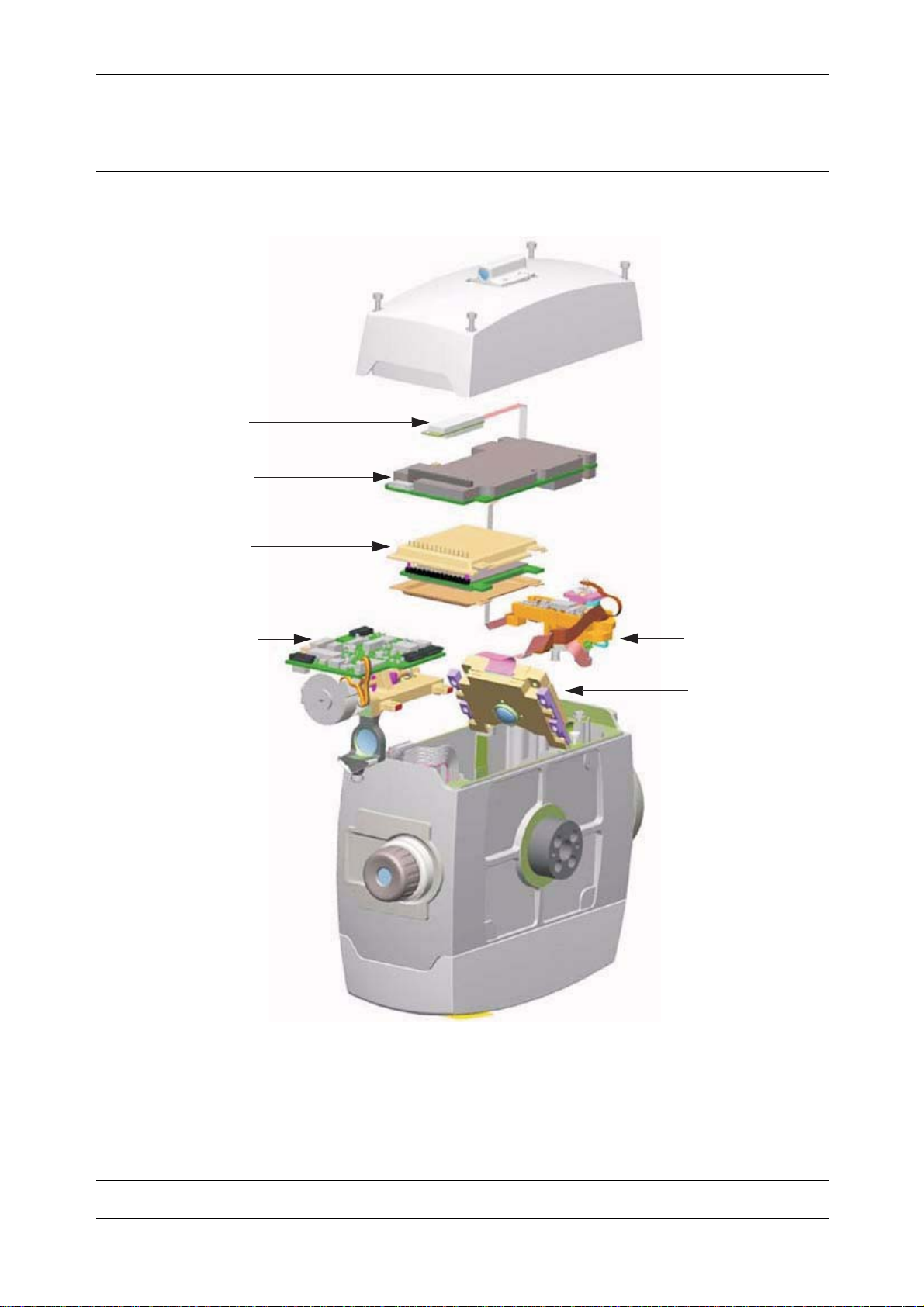
Chapter 3
F
Fig. 3-4 Tracker unit & Servo focus parts
TFB board
OTC board
OTA board
Theory of Operation
Servo focus
Tracklight
OTR
P/N 57150002, Revision 5.0 3 - 5 Trimble S, VX, SPS & RTS Service Manual
Page 62

Chapter 3
F
Fig. 3-5 Tracker Long Range or High Power Laser & Tracker unit / Servo focus parts
TFB board
OTC2 board
OTA board
Theory of Operation
Tracker Long Range (TLR)
High Power Laser (HPL)
or
module
Servo focus
OTR
Trimble S, VX, SPS & RTS Service Manual3 - 6 P/N 57150002, Revision 5.0
Page 63

Chapter 3
F
Theory of Operation
Removable handle
The handle is the carrying part of the instrument. The handle can be removed.
Location of handle
Fig. 3-6 Handle location
Handle
Function description
To remove the handle loosen the two screws and pull off the handle.
There are two types of locking screws for the handle, one larger which is easier to unlock. To mount
the larger screws in the handle see page 5-8.
Service
Replacement of spare parts
• Handle complete
• Yellow and black plastic parts
P/N 57150002, Revision 5.0 3 - 7 Trimble S, VX, SPS & RTS Service Manual
Page 64

Chapter 3
F
Theory of Operation
Battery / radio side cover
The left side cover of the Trimble S-series can be equipped with a radio / battery side cover or a
battery side cover. The only visual difference is the antenna.
Location of side cover
Fig. 3-7 Battery or radio side cover location
Battery
side cover
Detailed function description
The battery / radio side cover includes:
• Internal battery compartment
• BRC board incl. connector to internal battery
• Radio module incl. antenna and cable
Trimble S, VX, SPS & RTS Service Manual3 - 8 P/N 57150002, Revision 5.0
Radio
side cover
Page 65

Chapter 3
F
Fig. 3-8 Battery / radio side cover exploded
Theory of Operation
Internal battery compartment
One function of the side cover is to carry the internal battery unit that support the instrument. This
battery unit slides inside the battery lid and when the cover is closed and locked by Snap lock it will
make contact to the connector on the BRC board mounted in the side cover.
P/N 57150002, Revision 5.0 3 - 9 Trimble S, VX, SPS & RTS Service Manual
Page 66

Chapter 3
F
BRC board
Fig. 3-9 Battery / radio side cover block diagram
Battery / radio
side cover
Radio
BRC
board
Battery
Theory of Operation
PSM board
The BRC-board has two functions:
1. Includes the connector and ESD protection for the internal battery.
2. Connection to radio module and converting the radios RS232 to USB for communication to
IPC board.
Radio module incl. antenna and cable
Battery / radio side cover can be fitted with a radio module, see for description of the radio function.
Service
Replacement of spare parts
• Complete side cover without radio module
• BRC board
• Radio module
• Battery lid
Trimble S, VX, SPS & RTS Service Manual3 - 10 P/N 57150002, Revision 5.0
Page 67

Chapter 3
F
Theory of Operation
Radio unit
Introduction
The Trimble S instrument is available with an internal radio to support robotic operations. The radio
operates in the public / free 2.4GHz ISM band. The radio utilizes frequency hoping technology in the
2.4GHz band to reduce radio interference and maintain radio communications in even the harshest
RF environment.
Location of radio unit
The radio module is mounted on the BRC board in the left side cover.
Fig. 3-10 Radio unit location
Technical specifications
All models:
• Frequency range - Frequency hopping spread spectrum in the frequency range 2401 to 2470
MHz.
• Baud rate - 115Kb/s
Radio
unit
P/N 57150002, Revision 5.0 3 - 11 Trimble S, VX, SPS & RTS Service Manual
Page 68

Chapter 3
F
S6, S8, SPS & RTS models:
• Output power - 100mW
• Range - 1100m between instrument (1,8m antenna height) to robotic holder (1m antenna
height)
S3 Robotic model:
• Output power - 10mW, set by configuration number.)
• Range - 300m between instrument (1,8m antenna height) to TSC2 (1m antenna height)
Function description
The Georadio 2.4 uses the open ISM band on 2.4 GHz. It applies frequency hopping spread spectrum
technology. The radio meets FCC rules 15.247 and ETSI (European) 300.328 for worldwide license
free operation.
Fig. 3-11 Radio functional diagram
Theory of Operation
Radio module
The radio side cover consists of a radio module and a modem board. The modem board operates as a
link between the radio module and the instrument.
The Radio side cover and External radio are identical but the modem board and radio configuration
is different.
Radio software and configuration
The radio can be configured for different country specific settings.
Radio module
The radio module is WIT2410 from Cirronet. It applies frequency hopping spread spectrum in the
frequency range 2401 to 2470 MHz. The radio handles both data and control at up to 115 Kb/s.
Antenna
The antenna connector on radio side cover and external radio is a reversed polarity TNC-RP-MMCX
connector.
Modem board - BRC board
The BRC board converts the radios RS232 signals to IPC’s USB communication. The board also
contains power supply/supervision, ESD protection.
BRC board
IPC
Trimble S, VX, SPS & RTS Service Manual3 - 12 P/N 57150002, Revision 5.0
Page 69

Chapter 3
F
Radio configuration
The radio side cover/external radio can be configured for different country specific settings:
• Setting of Base (internal radio) or Remote (external radio)
• Output power
• Baud rate
The configuration is stored in the BRC board. If the BRC board is replaced, radio needs to be
configured for the country.
Service
Maintenance
Configuration of radio is done via the service software.
No adjustments such as the AFC adjustments on the old Georadio exist on the Georadio 2.4. Only
function test and range test is necessary.
The radio output power (10mW) for the S3 Robotic is set by the instruments configuration number.
Replacement of spare parts
• Radio module
Theory of Operation
• BRC board
P/N 57150002, Revision 5.0 3 - 13 Trimble S, VX, SPS & RTS Service Manual
Page 70

Chapter 3
F
Theory of Operation
Servo side cover
The servo side cover includes the servo position and servo focus knobs. The cover also includes a
Trigger key.
Location of side cover
Fig. 3-12 Servo side cover location
servo side cover
Function description
The servo side cover includes:
• Horizontal servo knob
• Vertical servo knob
• Servo focus knob
• Trigger key with LED
• KNB board
Trimble S, VX, SPS & RTS Service Manual3 - 14 P/N 57150002, Revision 5.0
Page 71

Chapter 3
F
Fig. 3-13 Servo side cover exploded
Theory of Operation
The cover includes a KNB board. The function of the KNB board is to read the movement of the servo
and focus knobs, also to detect the pressed button.
The knob is mounted to a bearing that is snapped into the cover. Two shims, sealing ring, distance
and a magnet completes the servo knob.
Fig. 3-14 Servo side cover
Servo
side cover
IPC board
KNB
board
P/N 57150002, Revision 5.0 3 - 15 Trimble S, VX, SPS & RTS Service Manual
Page 72

Chapter 3
F
KNB board
The KNB board contains "Hall" effect sensors that read the rotation of the magnet. The magnets are
magnetized in 3 sections. The "Hall" sensors create a signal corresponding to the knob movement.
The signal is sent to the IPC board
The KNB board also includes a function for the trigger button and LED indication.
Service
Maintenance - Servo knob calibration
A calibration of the servo and focus knobs are made in the service software if the KNB board is
replaced or removed. The calibration will read the signal from the "Hall" effect sensors during
movement of the magnet (knob) and create a table for optimum performance under different
temperature conditions.
Replacement of spare parts
• Side cover complete
• KNB board
• Trigger key
Theory of Operation
NOTE: The servo knobs can not be replaced. If knobs are broken the cover is replaced.
Trimble S, VX, SPS & RTS Service Manual3 - 16 P/N 57150002, Revision 5.0
Page 73

Chapter 3
F
IPC board
IPC board is the main board in the instrument, contains storage of firmware, supplies power, controls
angle and servo system.
Location
The IPC board is mounted to the alidade and located inside the servo side cover.
Fig. 3-15 IPC board location
IPC board
Theory of Operation
P/N 57150002, Revision 5.0 3 - 17 Trimble S, VX, SPS & RTS Service Manual
Page 74
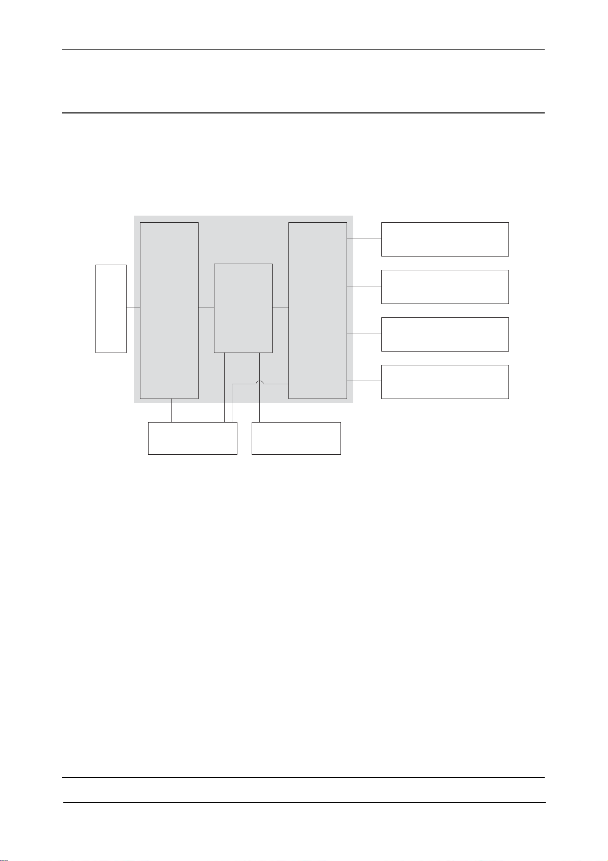
Chapter 3
F
Function description
Block diagram
Fig. 3-16 IPC board block diagram
IPC board
IM
Servo knobs
Hub
Theory of Operation
Centre unit
(vertical sliprings)
Vertical angle unit
& servo motor
PCS
Horizontal angle unit
& servo motor
Accelerometer
PSM board
IPC board consists of two main functions:
• IM - Instrument manager
• PCS - Position Control system
For information about the firmware in the instrument see page 3-52.
IM - Instrument manager
The IM part contains a micro controller, memory circuits, USB communication and power function.
IM handles the communication inside the instrument to the internal units/boards and external
communication via the base unit connector. The internal and external communication is done by
USB.
The IM function is equivalent to the PVX (excluding power) board in the Trimble 5600 series.
PCS - Position Control system
The PCS part contains same as IM a micro controller, memory circuits, USB communication and
power function.
PCS's main function is to control angle and servo system. It calculates angles with data from the angle
sensors and tilt sensor, converts this to an angle. IPC Also provides power to the horizontal and
vertical servo motors. The board controls the servo motors.
Tilt sensor
Trimble S, VX, SPS & RTS Service Manual3 - 18 P/N 57150002, Revision 5.0
Page 75
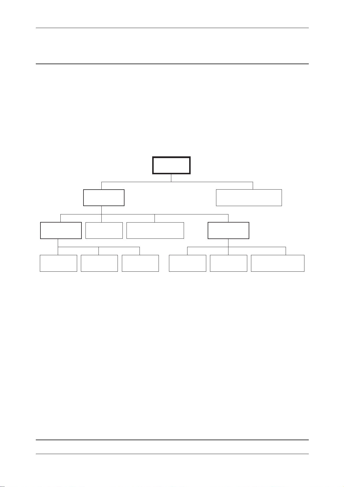
Chapter 3
F
The PCS function is equivalent to the POA/PAC & SRV boards in the Trimble 5600 series.
USB structure
IM communicates to all satellites/units direct or via a hub. There are three hubs in the USB structure,
one in the IPC board, one in the PSM board and one in the SFC board. These hubs helps IM to
communicate with more units.
IM is the host when communicating with internal units. When communicating via the foot connector
IM can be either host or device mode depending on the external unit.
Fig. 3-17 USB structure in the S6 instrument
Theory of Operation
IM
IPC hub
Foot connector
PSM hub
PSM
Service
Maintenance
After replacement of IPC board:
• Update firmware, see page 6-31
• Initialize instrument data, see page 6-7
Replacement of spare parts
• IPC board
PCS Tilt sensor
Radio TCU SFC Tracker
SFC hub
Distance unit
P/N 57150002, Revision 5.0 3 - 19 Trimble S, VX, SPS & RTS Service Manual
Page 76

Chapter 3
F
Theory of Operation
TCU attachment
The TCU attachment is the interface between the Trimble S6 instrument and the Trimble CU.
The TCU attachment is not available on the Trimble S3 instruments. The Trimble S3 Robotic Total
Station is equipped with a Face 1 cover instead of the TCU attachment. The Trimble S3 Servo/
Autolock Total Stations is equipped with a fixed control panel.
Location of TCU attachment
Fig. 3-18 TCU attachment location
TCU attachment
Function description
The TCU attachment includes:
• FPB board
• Balance weight
• Replaceable lock for the TCU
Trimble S, VX, SPS & RTS Service Manual3 - 20 P/N 57150002, Revision 5.0
Page 77
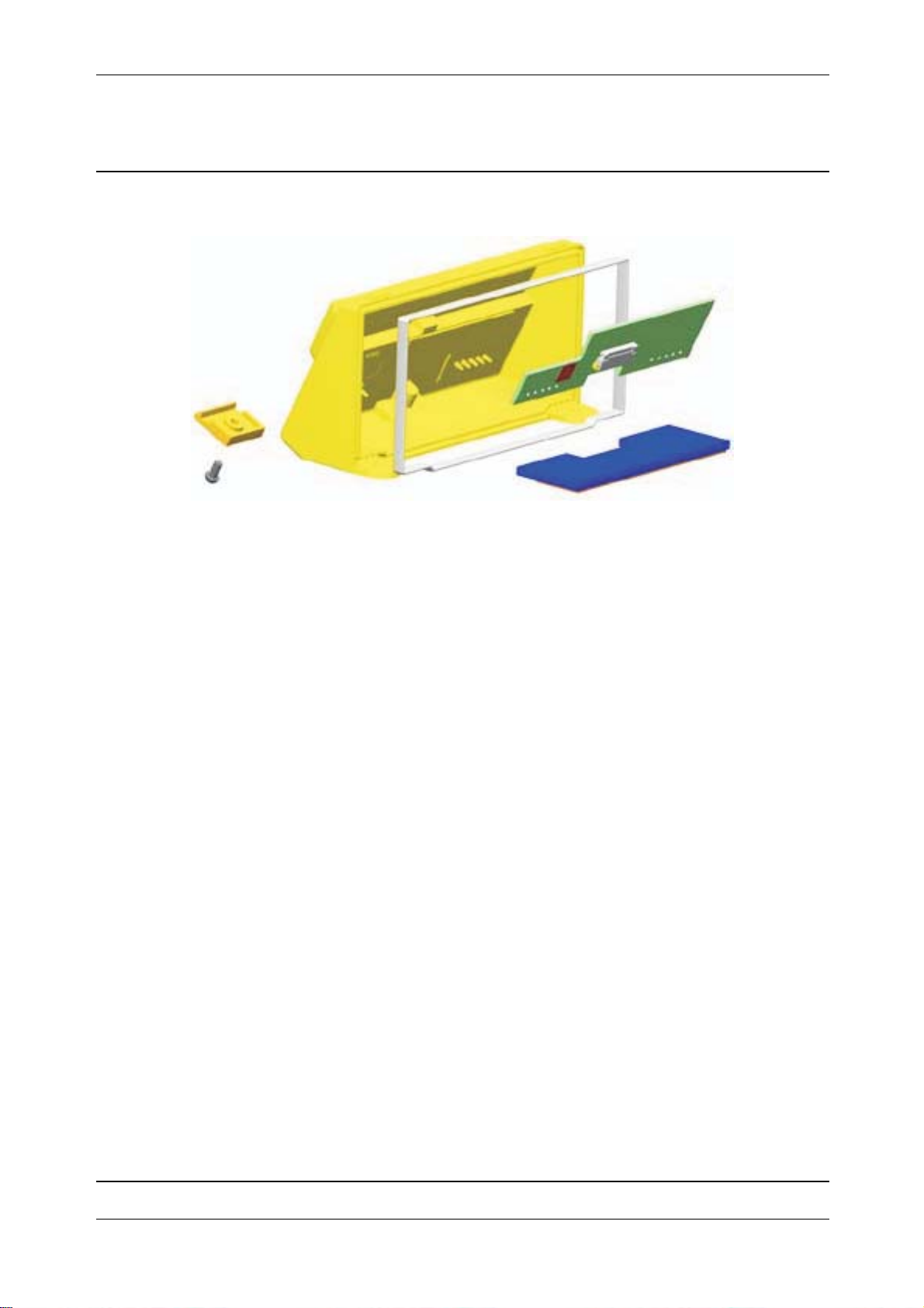
Chapter 3
F
Fig. 3-19 TCU attachment exploded
FPB board
A connection board, FFB board is mounted in the TCU attachment.
Theory of Operation
Service
Replacement of spare parts
• TCU attachment complete
• Lock for Trimble CU
P/N 57150002, Revision 5.0 3 - 21 Trimble S, VX, SPS & RTS Service Manual
Page 78
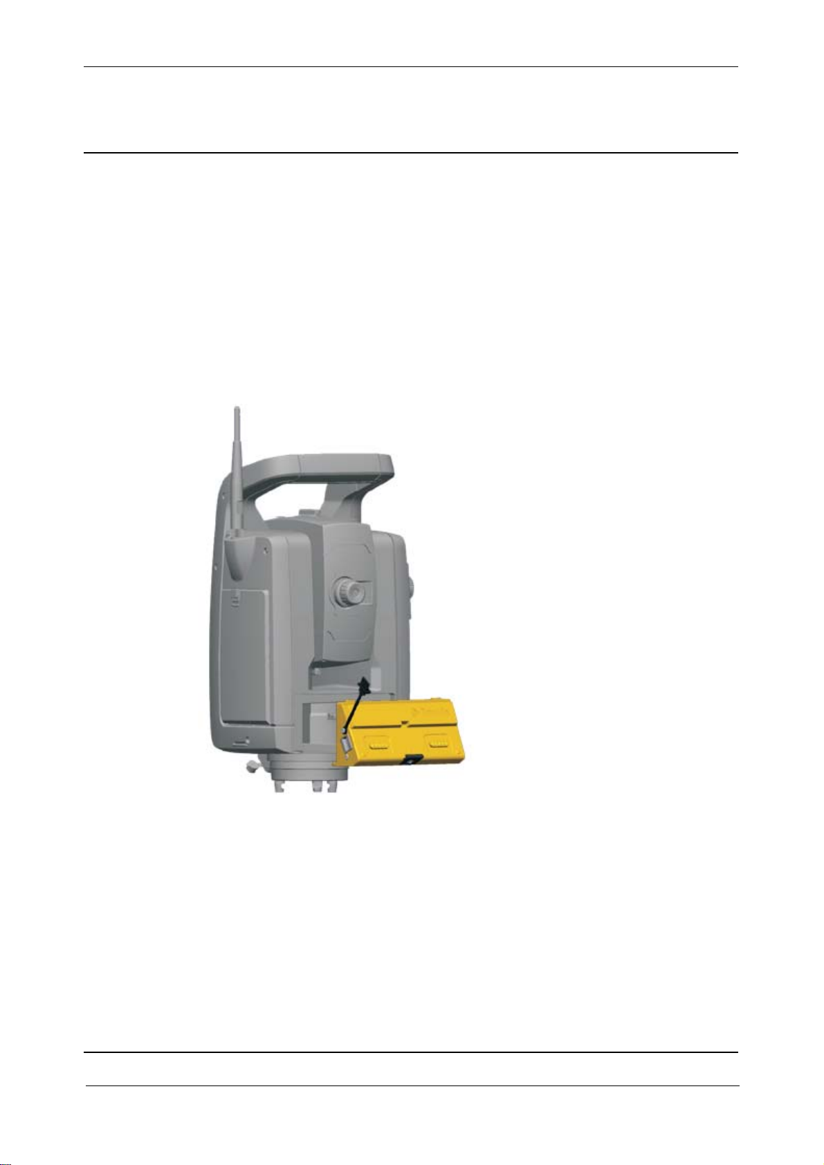
Chapter 3
F
Theory of Operation
TCU attachment with USB
The TCU attachment is the interface between the Trimble S Series instrument and the Trimble CU.
A USB connector on the side of the TCU attachment allows the user to connect a USB memory stick
to transfer files from and to the TCU.
The TCU attachment is not available on the Trimble S3 instruments. The Trimble S3 Robotic Total
Station is equipped with a Face 1 cover instead of the TCU attachment. The Trimble S3 Servo/
Autolock Total Stations is equipped with a fixed control panel.
Location of TCU attachment with USB
Fig. 3-20 TCU attachment location
TCU Attachment
with USB
Function description
The TCU attachment with USB includes:
• FPBTR board
• USB Board
• Balance weight
• Replaceable lock for the TCU
Trimble S, VX, SPS & RTS Service Manual3 - 22 P/N 57150002, Revision 5.0
Page 79
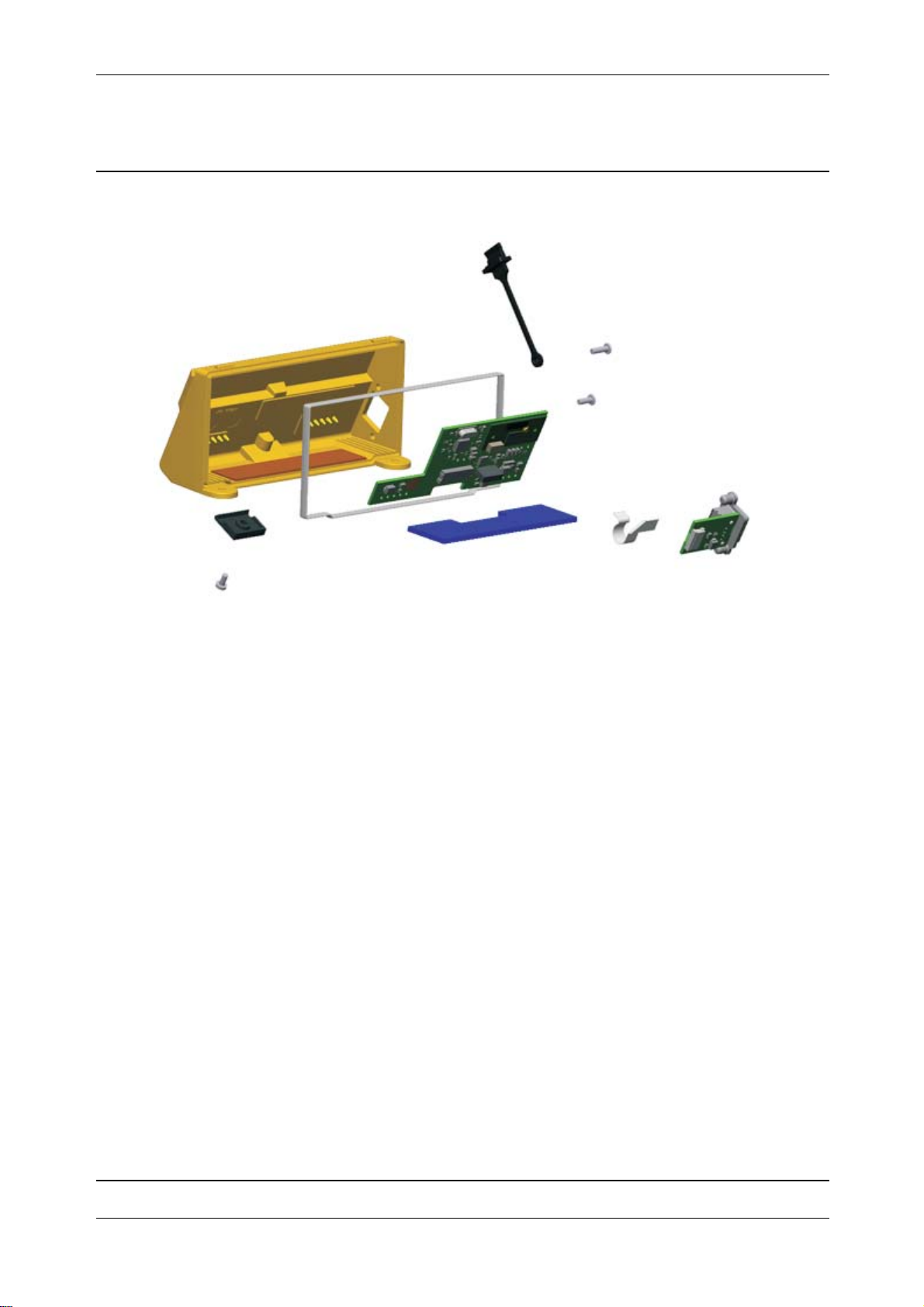
Chapter 3
F
Fig. 3-21 TCU attachment with USB exploded
Theory of Operation
FPBTR board
A connection board, FPBTR board is mounted in the TCU attachment.
USB Board
A connection board, USB board is mounted in the TCU attachment and connected to the FPBTR
board with a cable.
Service
Replacement of spare parts
• TCU attachment complete
• USB Board
• Cable between USB Board and FPBTR Board
• USB Connector dust cover
• Lock for Trimble CU
P/N 57150002, Revision 5.0 3 - 23 Trimble S, VX, SPS & RTS Service Manual
Page 80
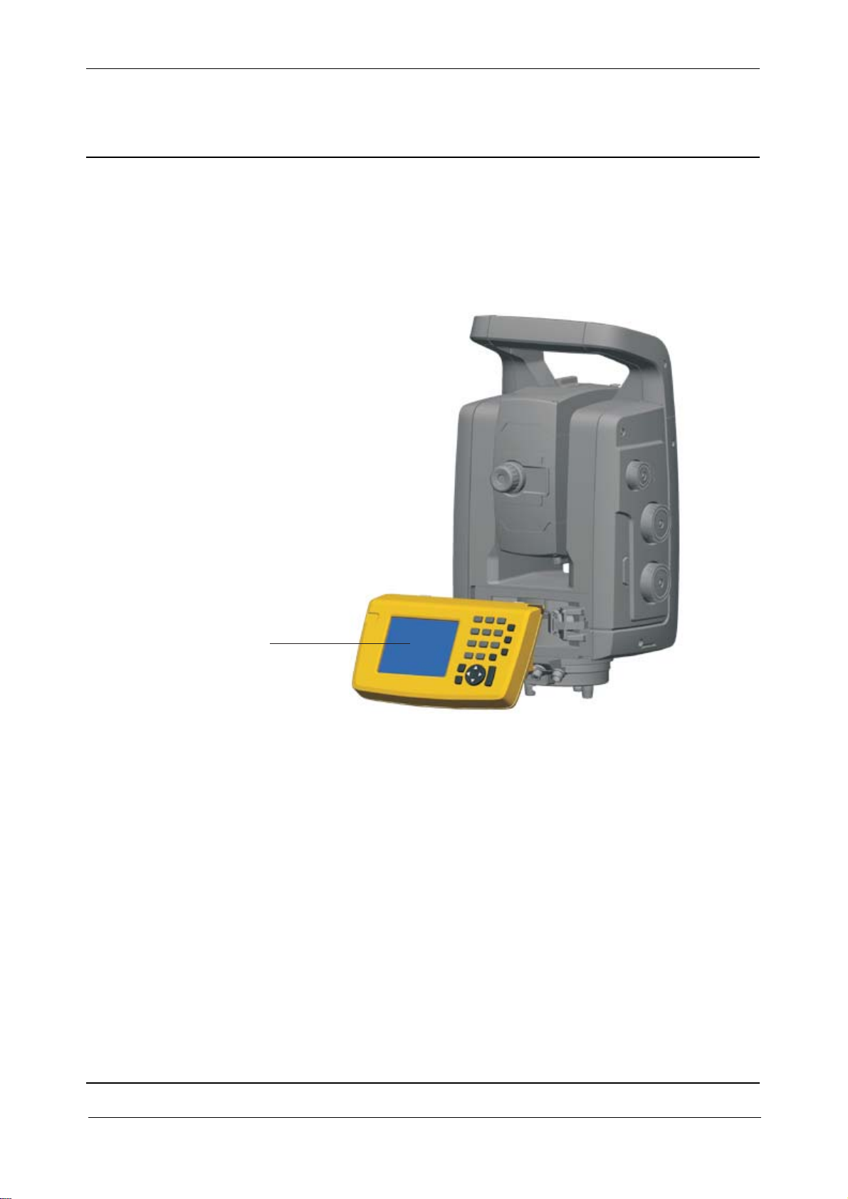
Chapter 3
F
Theory of Operation
Control Panel
The control panel of the Trimble S3 Servo/Autolock Total Stations are fixed to the instrument.
Location of Control Panel
Fig. 3-22 Control panel location
Control panel
Function description
The Control panel includes:
• HRU board
• IAB Board
• Quimby Board
• KBDQ Board
• Display 3.5”
Trimble S, VX, SPS & RTS Service Manual3 - 24 P/N 57150002, Revision 5.0
Page 81

Chapter 3
P1J1
SIDE_ D+
USBVDD
SIDE_ D-
OT G_ ID
GN D
UC PW R
F
Fig. 3-23 Control panel exploded
Theory of Operation
HRU Board
IAB Board
Quimby Board
Display 3.5”
KBDQ Board
HRU board
This board has two functions, providing mechanical mounting for the external Hirose connector and
ESD protection.
Fig. 3-24 HRU Function diagram
P/N 57150002, Revision 5.0 3 - 25 Trimble S, VX, SPS & RTS Service Manual
Page 82
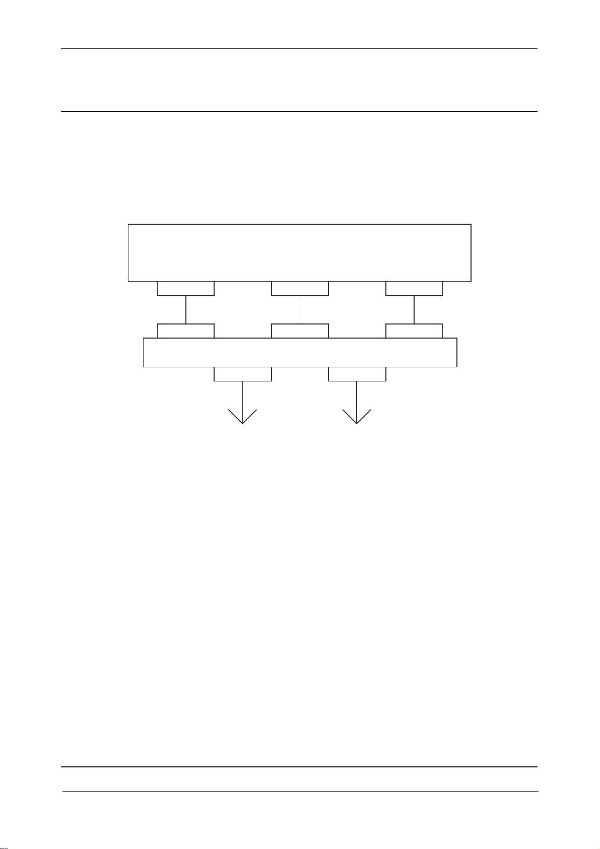
Chapter 3
Quimby CPU board
P8 P7
IAB
P1 P2
J1
To Trimble S6
P2
P4
P3
To Side Hirose(HRU)
F
IAB board
The main functionality of the IAB board is to provide an interface between the Quimby CPU board
and the instrument. It also contains a power source to enable the Quimby main board to remain in
suspend while the battery is exchanged in the instrument.
Fig. 3-25 IAB Function diagram
Theory of Operation
Quimby Board
The Quimby board is the CPU and memory board of the control panel. The memory is 128Mb.
KBDQ Board
The function of the KBDQ Board is to detect key press from the 22 keys on the control panel
keyboard.
Service
Replacement of spare parts
• TCU attachment complete
• Lock for Trimble CU
To instrument
Trimble S, VX, SPS & RTS Service Manual3 - 26 P/N 57150002, Revision 5.0
Page 83

Chapter 3
F
Theory of Operation
Face2 panel & optical plummet
The Face2 panel is a graphical display with built in backlight. It is controlled with three buttons,
change face, scroll and enter.
When a Control Unit is attached to the instrument, the application software running in the TCU will
have control over the face2 display and keyboard.
The optical plummet allows the instrument to be positioned to an accuracy of 0.3 mm from an
instrument height of 1.5m over a ground mark.
The Face 2 panel is not available on the Trimble S3 instruments (Face 2 panel available on Trimble
S3 Servo/Autolock on some markets). The Trimble S3 Total Station is equipped with a Face 2 cover
instead of the Face 2 panel. The optical plummet is not available on Trimble S3 Total Station and has
been replaced with an optical plummet in the tribrach.
Location of Face2 display & optical plummet
Fig. 3-26 Face 2 display & optical plummet location
Face 2 panel incl.
optical plummet
Technical specifications
Optical plummet
Focusing range: 0,5 m to infinite.
Accuracy/range: ± 0.3 mm/1.5 m
Field of view: ± 2.5
Magnification: 2.3
P/N 57150002, Revision 5.0 3 - 27 Trimble S, VX, SPS & RTS Service Manual
Page 84
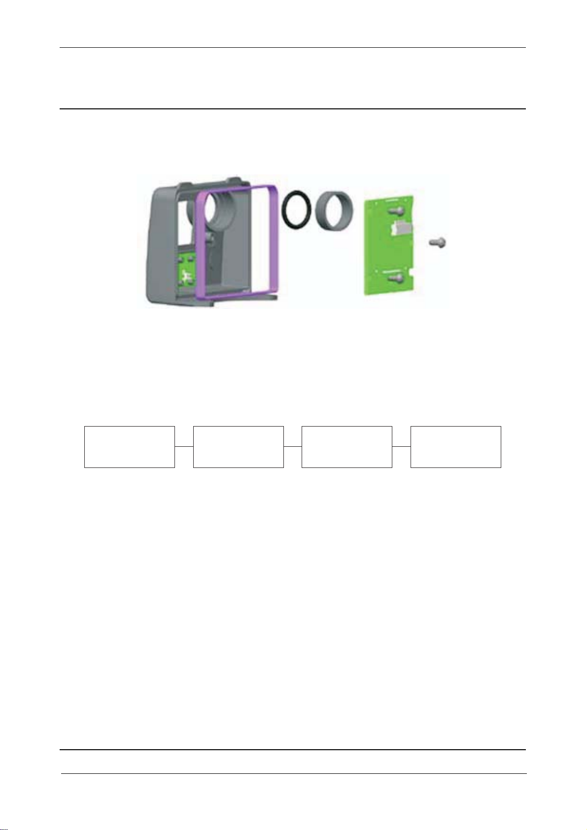
Chapter 3
F
Function description Face2 panel
Fig. 3-27 Face2 display unit exploded
The Face2 panel includes:
• F2D board & display
• Back cover incl. keyboard
Theory of Operation
• Hole for optical plummet incl. seal
Fig. 3-28 Face2 panel block diagram
Back cover incl.
Keyboard
The keyboard (Face2 Buttons) is connected to the IPC board via F2D and PSM boards.
F2D board & display
The F2D board (Face2 Display board) contains a LCD Display Module with back illumination.
The F2D/LCD data signals are fed from the IPC Board via the PSM Board.
Back cover incl. keyboard
The keyboard is a 3 push-button to control the Display. The back cover is connected to F2D board
with a 4-pin board-to-board connector.
Face 2 panel compatibility
The face2 panel exists in two versions, one with a new display requiring firmware R2.1.0 or higher.
When replacing the face2 panel it is necessary to update face2 panel settings, see page 6-20.
F2D board
& display
PSM board IPC board
Wrong setting will only cause the face2 panel to show wrong characters, update the setting and the
face2 panel will work correctly.
Trimble S, VX, SPS & RTS Service Manual3 - 28 P/N 57150002, Revision 5.0
Page 85
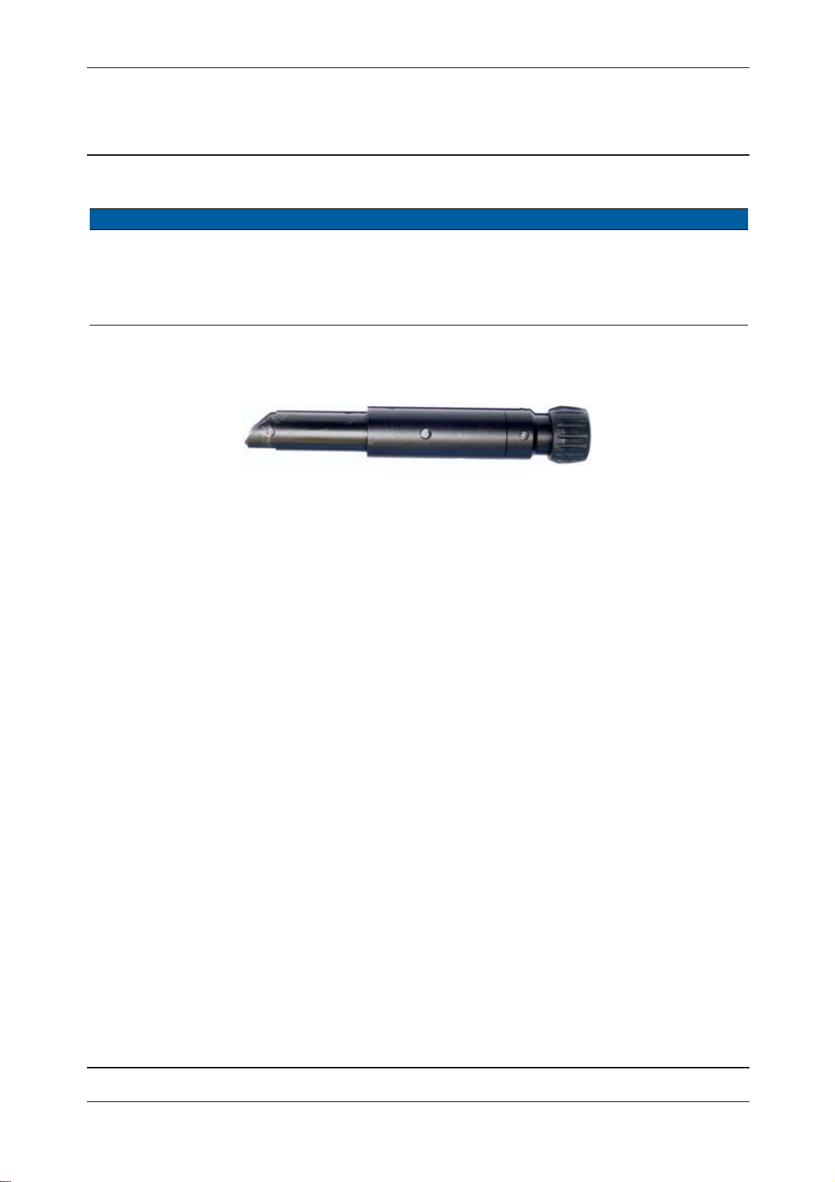
Chapter 3
F
Face 2 panel compatibility
Face 2 panel label Variable in PASS Firmware compatibility
C00/01 0 All firmware versions
C00/02 01 1 R2.1.0
02 2 R2.1.0
03 3 or higher - RoHS R2.1.0
Function description optical plummet
Fig. 3-29 Optical plummet
The optical plummet is used to position the instrument above a point.
Face2 display functionality
Theory of Operation
See page 3-59 for information about the face2 display functions when starting up the instrument.
Service
Maintenance
Alignment of optical plummet.
Replacement of spare parts
• Face 2 panel complete
• Optical plummet
P/N 57150002, Revision 5.0 3 - 29 Trimble S, VX, SPS & RTS Service Manual
Page 86

Chapter 3
F
Theory of Operation
Pressure sensor
The instrument has an internal barometer. This sensor is capable of providing temperature and
atmospheric pressure readings. The sensor also contains a thermometer but it is not used.
The application software in the TCU uses the pressure information to calculate the PPM correction
for the EDM. Note: this correction is not made in the instrument and is available for the application
software.
The Pressure sensor is not available on the Trimble S3 and SPSx20 instruments.
Location of sensor
Fig. 3-30 Pressure sensor location
Function description
The sensor is connected to the PSM board which is responsible for controlling the sensor. Specific
parameters are included in the sensor such as correction values for the barometer.
Service
Maintenance
The Pressure sensor is calibrated from the supplier. A connection test is made after installation.
Replacement of spare parts
• Pressure sensor
Trimble S, VX, SPS & RTS Service Manual3 - 30 P/N 57150002, Revision 5.0
Page 87

Chapter 3
F
Theory of Operation
Servo drive system
The Trimble S6 Total Station incorporates a revolutionary servo angle system called MagDriveTM
servo technology. MagDrive servo technology is based on a direct drive and frictionless
electromagnetic drive technique. The direct drive system allows the servo motors to be mounted
directly on the horizontal and vertical axis, removing the need for additional mechanical gearing. The
integration with the angle sensor enhances the speed of the servo motors by providing fast angle
values to be used by the servo processor. MagDrive servo technology provides high accuracy, high
speed turning servo capabilities with low power consumption. The frictionless motion also removes
servo noise and reduces instrument wear. The system provides endless motion in horizontal and
vertical direction including endless fine adjustment without mechanical clutches.
The angle sensor is integrated with the servomotor and built into the servo housing on the same axis.
The motor winding is attached to the angle board and final calculations of angle values are made in
the IPC board. No additional encoder or tachometer will then be needed in the system. The main angle
sensors will give a direct, fast feedback to the servo controller.
With this motor design the transmission of force from the motor to rotate the instrument will take
place non-contacting, frictionless, according to known electro-magnetic field theory. The motor is
designed with a magnet holder containing magnets and soft iron areas distributed in two concentric
cylindrical structures separated by an air gap, in which there is space for the cylinder formed motor
winding. To drive the motor a current is fed through the motor winding generating a force to rotate
the magnet holder and the instrument.
This motor design will create an exceptional performance compared to conventional technique:
• Fast and accurate system
• Very low noice level
• No wear of component
• Low weight and power consumption
The servo system uses the angle system for position angle feedback information and commutation of
electrical phases.
P/N 57150002, Revision 5.0 3 - 31 Trimble S, VX, SPS & RTS Service Manual
Page 88

Chapter 3
SRC board incl. magnets
SRC board
incl. magnets
MSB board
incl. motor winding
MSB board
incl. motor winding
F
Location of servo system
Fig. 3-31 Servo unit location
Theory of Operation
Technical specifications
Speed: 2 rad/s (115°/s), Speed for Trimble S3: 1.5 rad/s (85°/s)
Acceleration: 3 rad/s2
Positioning speed: 180° takes 3,2 s
Accuracy: 1cc
Function description
The servo system contains of:
• SRC board incl. magnets
• Motor winding mounted on the MSB board
• Two accelerometers for horizontal servo system
Trimble S, VX, SPS & RTS Service Manual3 - 32 P/N 57150002, Revision 5.0
Page 89

Chapter 3
SRC board
MSB board incl. motor winding
incl. magnets
F
Fig. 3-32 Horizontal servo system parts
Theory of Operation
SRC board incl. magnets
Contains the magnet side of the motor. The magnets are placed in an outer and inner circle of the
motor winding.
The SRC, slip-ring board is attached to the magnet holder providing current and a communication to
the vertical axis (IPC board) and horizontal axis (PSM board).
MSB board incl. motor winding
The motor winding is mounted on the MSB board. All other functions on the MSB board are used by
the angle system.
How it works
The servo motor is an electromagnetic motor that uses the known physics relation between current,
magnetic field and force to move the motor
P/N 57150002, Revision 5.0 3 - 33 Trimble S, VX, SPS & RTS Service Manual
Page 90
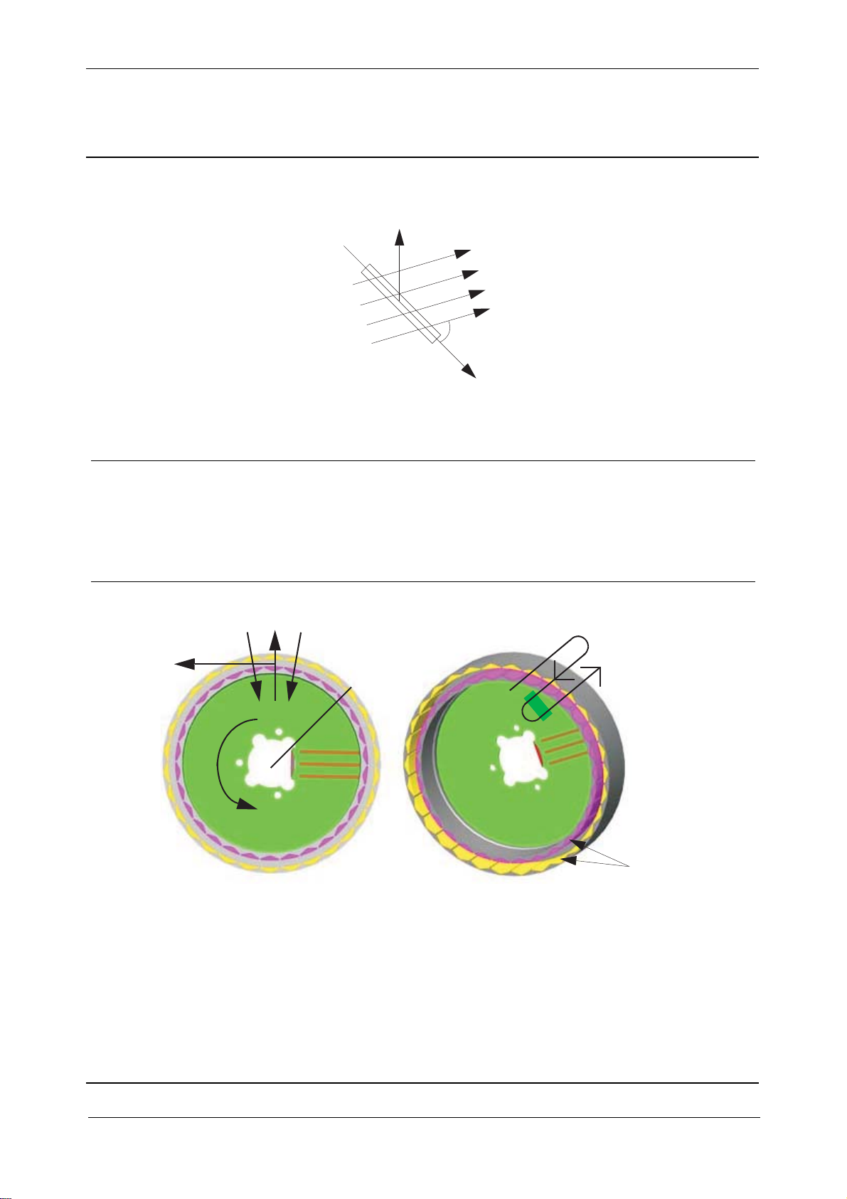
Chapter 3
F
Fig. 3-33 Basic principle
F=BIL*sinA
L
A
The equation to calculate the force vector F is the known formula:
F= B*I*L*sinA
Where: F is the force vector (Newton), perpendicular to the plane defined by B and I
B is the magnetic field (Tessla)
I is the current (Ampere)
Theory of Operation
B
I
L is the length (Meter)
SinA is the angle between the current and the magnetic field
Fig. 3-34 Magnetic holder principle
B
F
R
M
The force F is acting on the radius R.
Torque M can then be calculated.
I
Magnets
M = B*I*L*R*sinA, Since sinA is 90=1 it can be simplified to:
M = B*I*L*R
Trimble S, VX, SPS & RTS Service Manual3 - 34 P/N 57150002, Revision 5.0
Page 91

Chapter 3
F
Trimble servo system
To drive the motor a current is sent through the motor winding and generates a force to move the
motor (magnet holder or motor winding) forward.
The winding is divided in three phases to make it possible to control the movement of the motor. A
specific servo calibration procedure is made to detect the different magnetic fields for the motor
movement.
The motor has three different working modes:
• Driving mode. Where movement is controlled by servo knobs or system process.
• Friction mode. Where the motor allows the instrument to be turned manually. The magnetic
friction will generate a resistance against movement of the motor.
• Holding mode. Where the motor works as a clutch to lock the instrument position and prevent
movements, e.g when pressing a push-button as long as no positioning commands is given.
Positioning and control of the servo system is made by the processor board. The processor board also
contains firmware for the servo system.
Accelerometer
The horizontal servo system also contains two accelerometers, these accelerometers senses the
movement (vibration) of the instrument and send this information back to the servo system to increase
stability. The accelerometer removes certain frequencies and thereby eliminates undesired vibrations.
The two accelerometers compensates for e.g. mechanical weaknesses in the tripod.
Accelerometer no1 (front accelerometer) is positioned inside the TCU attachment and accelerometer
no2 (side accelerometer) is positioned inside the battery side cover.
Theory of Operation
Calibration
After replacement / removal & assembling of MSB board with motor winding / SRC board with
magnets / Accelerometers a calibration procedure must be made, this is done in PASS
The calibration detects the position of the magnetic field with respect to the electrical field in order
to be able to commutate the current correctly. The data is stored together with the instrument angles
corresponding to the working field.
Service
Maintenance
• Servo and angle system calibration (PASS)
Replacement of spare parts
• SRC board incl. magnets
• MSB board incl. motor winding
• Accelerometers
P/N 57150002, Revision 5.0 3 - 35 Trimble S, VX, SPS & RTS Service Manual
Page 92
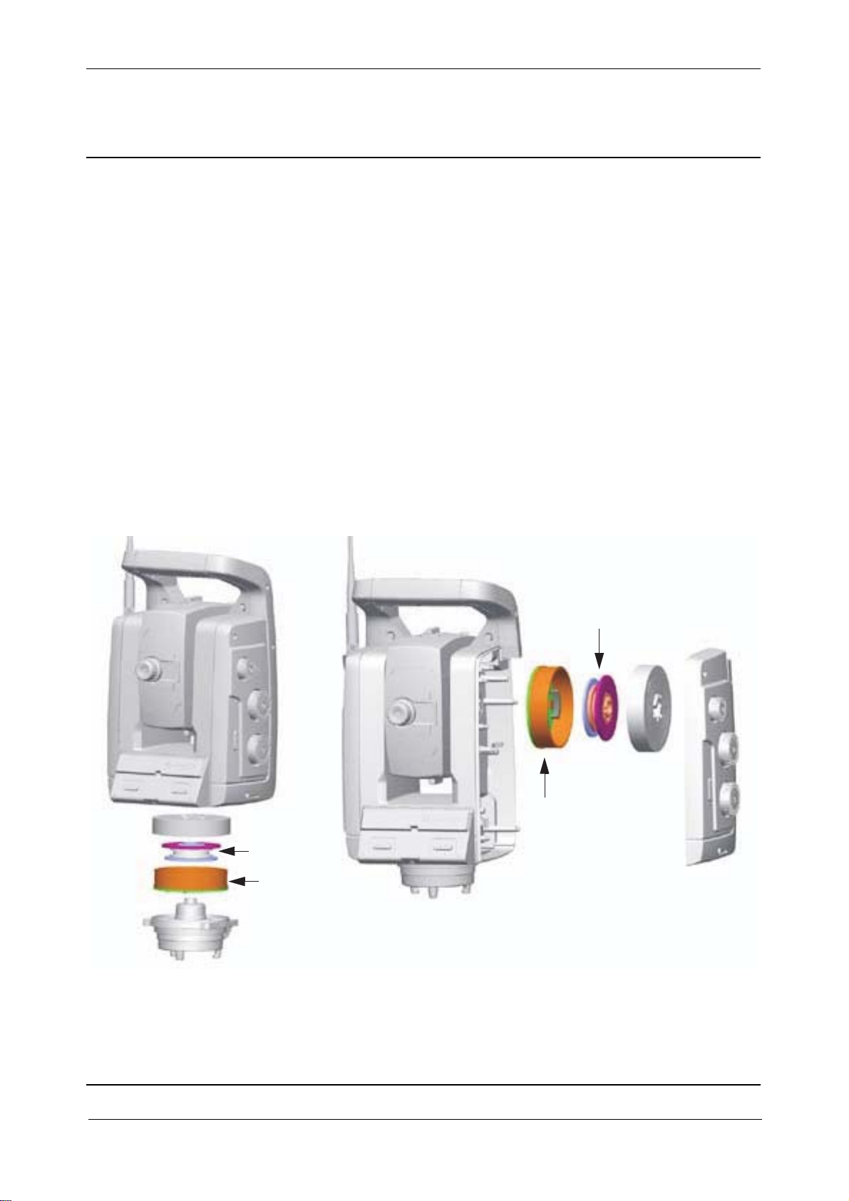
Chapter 3
F
Theory of Operation
Angle Measuring System
Trimble total stations have traditionally been leading in producing high measuring efficiency with
servo driven total stations admitting full angle accuracy in single-face measurements. The concept
with measurement and automatic correction of horizontal and vertical collimation errors and tilt axis
errors is still valid. Now, a new step in the direction of improved angle measurement and servo
function has been taken with the design of a new fully integrated servo and angle measuring system.
A new dual-axis level tilt sensor is also part of the system handling traditional levelling errors.
Angle sensor
The purpose of the angel sensor is to generate a vertical and horizontal angle for the instrument. The
angle sensor is based on an optical principle. Glass circles hold a pattern consisting of a coarse code
and a fine code admitting the presentation of an absolute angle value. Several improvements of
previously used principles have been made and are now under patent applications.
Location of angle unit
Fig. 3-35 Angle unit location
Horizontal
angle disc
MSB board
Technical specifications
Vertical angle disc
MSB board
• 1"-2" standard deviation depending on instrument model.
Trimble S, VX, SPS & RTS Service Manual3 - 36 P/N 57150002, Revision 5.0
Page 93
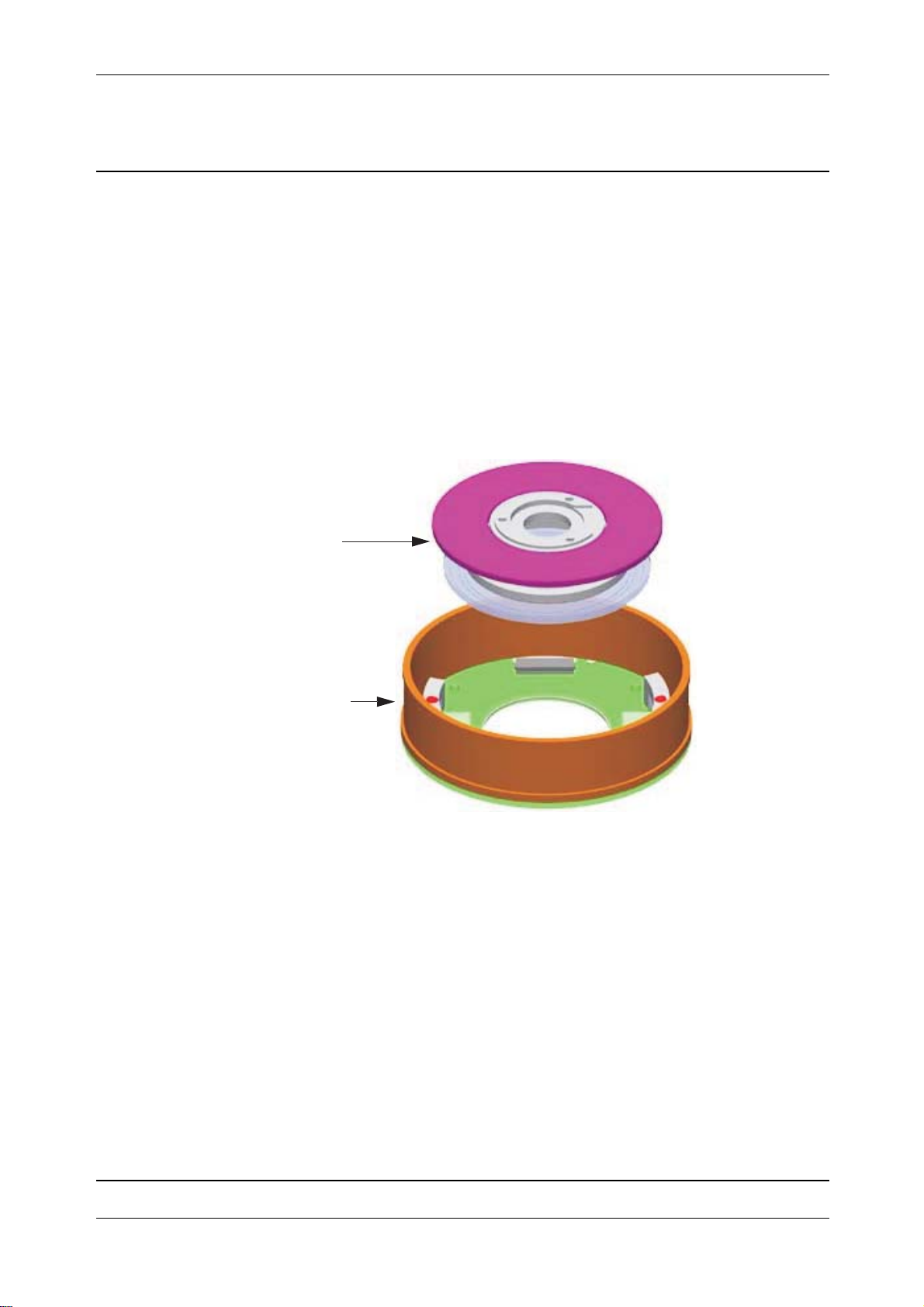
Chapter 3
F
Function description
Mechanically the angle unit is located as a fully integrated part inside the servo motor housing. The
motor protects the angle glass disc form dirt and dust. The centre unit, angle disc assembly contains
the optical glass disc. The angle board contains laser transmitter and image area detectors (CMOS
detectors), the angle board also includes the servo motor winding. All together this design creates a
rugged and accurate absolute encoder measuring angles with an accuracy of 0.2 mgon at a rate of
1000 Hz. The angle sensor is designed not only for displaying and storing angle data but also to
support the servo system with fast angle information. Final angle data calculations are made in the
IPC board.
Fig. 3-36 Horizontal angle system parts
Angle disc
Theory of Operation
MSB board incl.
motor winding
Angle disc
A mechanical centre unit holds a glass disc with optical encoder pattern and a mirror. By using two
separate tracks a uniform accuracy and resolution around the circle is obtained. Both tracks are
illuminated with a single laser light source and projected on a CMOS image area sensor. By using
one common sensor for both tracks usual alignment problems are eliminated. The design will be
compact and less parts have to be assembled.
The function of the disc assembly is the same for both horizontal and vertical sensor but the
mechanical axis is different due to how the disc is mounted.
MSB board incl. motor winding
Includes a LED and a detector, CMOS image area sensor.
The angle board is the same for both vertical and horizontal sensor and includes the motor winding.
P/N 57150002, Revision 5.0 3 - 37 Trimble S, VX, SPS & RTS Service Manual
Page 94
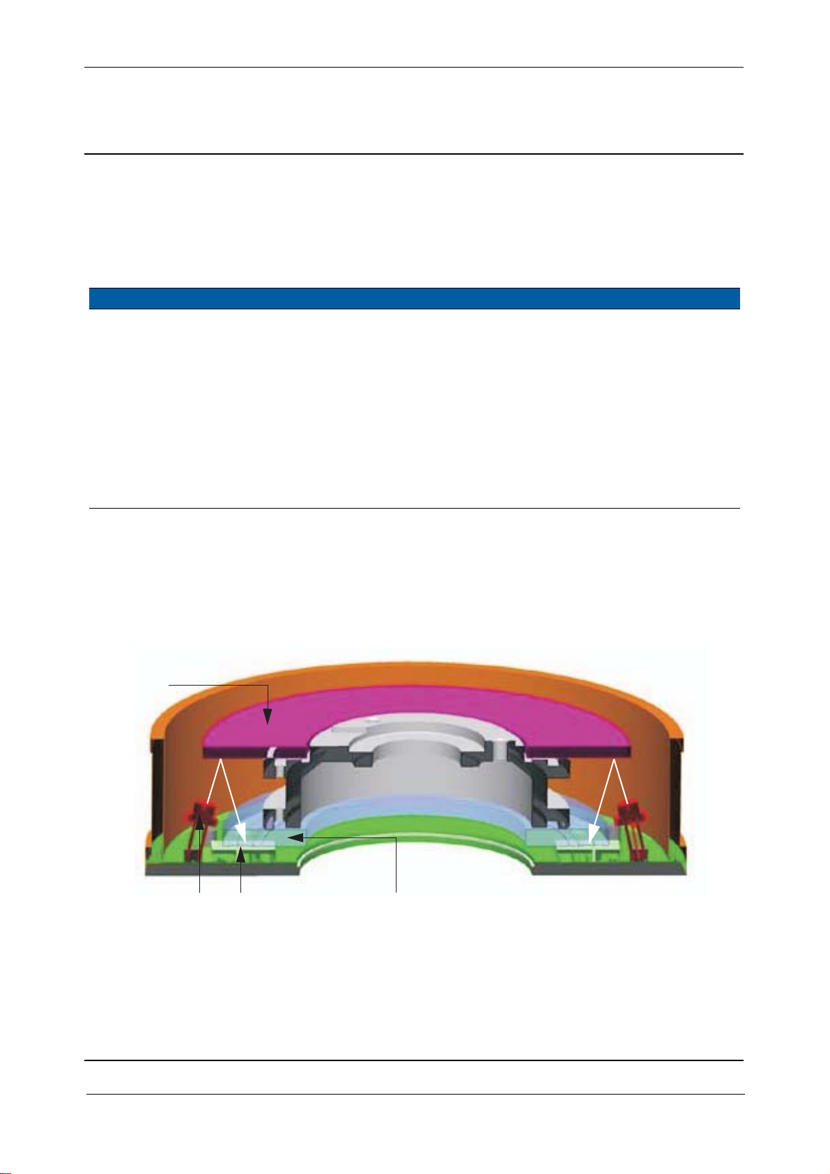
Chapter 3
F
MSB board compatibility
The horizontal and vertical MSB board MUST be of the of a compatible revision. Reason is that the
horizontal and vertical LED light sources on the MSB boards must be the same as they are driven
with the same parameters. See the table below for compatibility:
MSB board
Hor. MSB board version Vert. MSB board version Compatibility
1 1 Ver. 1 is ONLY compatible with ver. 1
3 3 Version 3, 4 & 5 are compatible with each other,
i.e. it is possible to have a horizontal MSB ver. 3
and a vertical MSB ver. 5.
44
55
6 6 Ver. 6 - RoHS is not compatible with earlier
versions.
7 7 Type in ver. 6
Theory of Operation
How it works
The LED light is reflected by a mirror through an encoder glass disc. A pattern from the encoder glass
disc is projected on the detector. The detector, a CMOS image area reads the pattern from the coarse
and fine code on the disc.
Fig. 3-37 Angle system incl. angle disc
Mirror
LED
CMOS detector
Encoder glass disc
The coarse code placed on the inner circle on the glass disc works like a bar code, the CMOS sensor
will identify the coarse position of the circle. The fine code placed on the outer circle of the glass disc
is an incremental code. By reading the coarse and the fine code an angle can be generated.
Trimble S, VX, SPS & RTS Service Manual3 - 38 P/N 57150002, Revision 5.0
Page 95
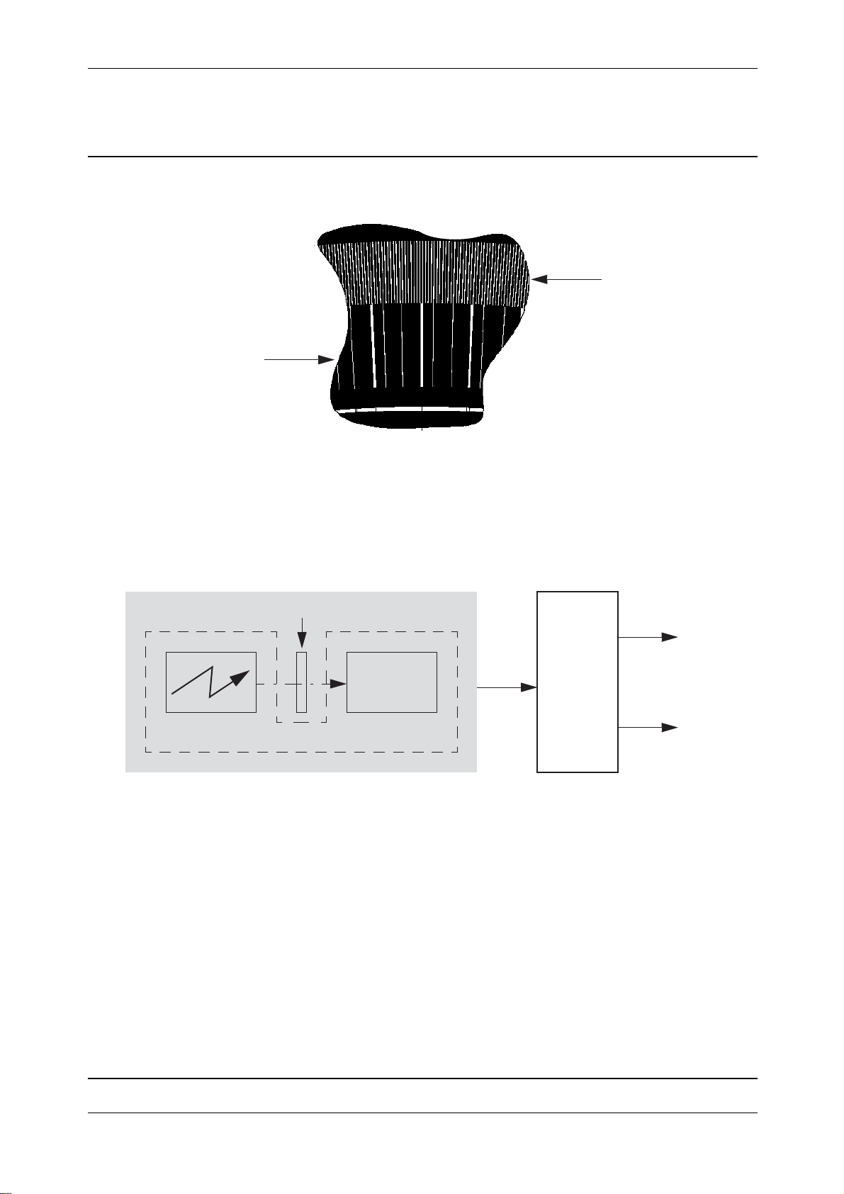
Chapter 3
F
Fig. 3-38 Coarse and fine code of the angle disc
Coarse code
The information from the CMOS image sensors is sent to the processor board for calculation and
conversion into an angle.
Block diagram
Theory of Operation
Fine code
Fig. 3-39 Angle unit block diagram
Angle unit
Angle disc
CMOS
Detector
MSB board
To make the absolute encoder robust and less sensitive to eccentric mounting errors two CMOS
detectors are positioned with 180 separation at the disk to read the tracks (coarse and fine code). The
final angle value is calculated as the mean value of these two readings and first order errors with same
size but different signs will be eliminated.
High angle accuracy instruments (0,5” & 1”)
Instruments with 0,5” & 1” angle accuracy includes a pre calibrated Horizontal Turning Unit. As long
as the Horizontal Turning Unit is kept together and the parts, SRC board with magnets / Angle disc /
MSB board are not removed the high angle accuracy is still valid.
IPC
board
Angles
Servo
unit
CU
Even if the parts are removed accidentally and assembled together the Horizontal Turning Unit needs
to be calibrated to achieve the high angle accuracy.
The calibration of the Horizontal Turning Unit is made in the factory.
P/N 57150002, Revision 5.0 3 - 39 Trimble S, VX, SPS & RTS Service Manual
Page 96
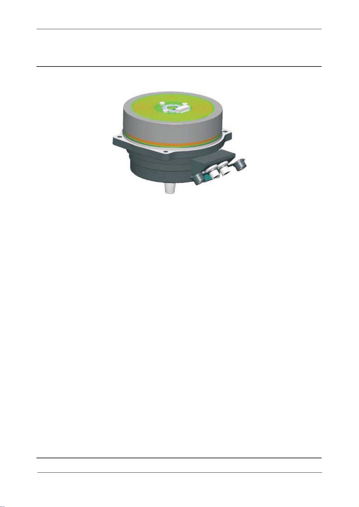
Chapter 3
F
Fig. 3-40 Horizontal Turning Unit High Angle Accuracy
Correction file
The Horizontal Turning Unit unit is calibrated at the factory and includes a correction table, this table
is stored in the IPC board in the instrument. When an angle is produced the correction table will then
improve and calculate the high angle accuracy.
Theory of Operation
The correction file is available on Partners / Service Instrument Constant Search.
Service
When replacing the Horizontal Turning Unit a new correction table needs to be installed in the
instrument.
Each Horizontal Turning Unit has a serial number and the correction table (file) has the same name.
Service
Maintenance
• A centering tool is required when mounting the vertical MSB board incl. motor winding.
• Servo and angle system calibration (PASS)
Replacement of spare parts
• Horizontal angle disc
• Vertical angle disc
• MSB board incl. motor winding (horizontal and vertical are the same)
• 1” instruments - Horizontal Turning Unit 1”
Trimble S, VX, SPS & RTS Service Manual3 - 40 P/N 57150002, Revision 5.0
Page 97

Chapter 3
F
Automatic correction of angle values
In addition to the fast acquisition of accurate angles, the angle measurement system compensates for
the following:
• Automatic correction for deviation of the plumb axis.
• Automatic correction for collimation errors (HA/VA collimation & Tracker collimation).
• Automatic correction for trunnion axis tilt.
• Arithmetic averaging for reducing sighting errors.
Automatic correction for deviation of the plumb axis
Deviations in the plumb axis may occur when one (or more) of the tripod legs move as a result of
unstable ground or changes in ground viscosity, such as the heating of road tarmac. Corrections for
this movement are essential to ensure that accurate measurements are obtained.
In contrast to most total stations, MagDrive allows the Trimble S6 to correct not only the horizontal
and vertical angles for mislevelment, but also the aiming errors caused by mislevelment. The
mislevelment correction is applied to the servo drive to re-aim the instrument. For example,
correcting the aiming when extending a vertical line to ensure that a true vertical line can be obtained.
The result is that horizontal and vertical angles are corrected for mislevelment while the instrument
is accurately aimed at the correct location. This ability ensures that mislevelment errors are corrected
to provide accurate angle measurements.
Theory of Operation
Automatic correction for collimation errors (HA/VA collimation & Tracker (Autolock) collimation)
Collimation errors affect measured horizontal and vertical angles. The horizontal collimation error is
the difference between the line of sight and the plane perpendicular to the trunnion axis; the vertical
collimation error is the difference between the vertical circle zero and the plumb k s. Traditionally,
collimation errors were eliminated by observing angles on both instrument faces. In the Trimble S6
the collimation errors can be predetermined by performing a pre-measurement collimation test.
Angular measurements are observed on both instrument faces to enable the collimation errors to be
calculated and the respective correction values to be stored in the instrument. The collimation
correction values are then applied to all subsequent angle measurements. Angles observed on a single
face are therefore corrected for collimation errors, thereby removing the need to measure on both
instrument faces.
Trimble S6 instruments with Autolock technology can automatically lock and track a target. Since
the sighting to the target is performed by the instrument, the affects of horizontal and vertical
collimation are similar to those experienced during manual sighting. To correct for the collimation
errors in the tracker unit, an Autolock collimation test can be performed.
The Autolock collimation test automatically observes angular measurements to a target on both
instrument faces. The Autolock collimation errors are then calculated and the respective correction
values are stored in the instrument The Autolock collimation correction values are then applied to all
subsequent angle measurements observed when Autolock is enabled. Angles observed on a single
face are therefore corrected for collimation errors, thereby removing the need to measure on both
instrument faces.
P/N 57150002, Revision 5.0 3 - 41 Trimble S, VX, SPS & RTS Service Manual
Page 98

Chapter 3
F
Automatic correction for trunnion axis tilt
The trunnion axis tilt error is the difference between the trunnion axis and the plane perpendicular to
the plumb axis. In the Trimble S6 the trunnion axis tilt error can be determined by performing a pre
measurement trunnion axis tilt test. Angular measurements are observed on both instrument faces to
enable the horizontal tilt axis error to be calculated and the respective correction value to be stored in
the instrument. The horizontal tilt axis correction value is then applied to all subsequent horizontal
angles.
Arithmetic averaging for reducing sighting errors
The Trimble S6 automatically reduces sighting errors caused by misaligning the instrument to the
target or by movement during measurement. The sighting errors can be reduced by:
Using Autolock technology. When Autolock is enabled the instrument will automatically lock to and
track the target. Manual sighting errors are therefore reduced.
SurePoint accuracy assurance. When the Trimble S6 is manually aimed at a target the servo motors
are finely tuned to hold the aimed angle. SurePoint ensures that sighting errors due to unintentional
small movements of the instrument are eliminated. SurePoint is not available on the Trimble S3 Total
Station.
Theory of Operation
Automatically averaging angles during distance measurement. When measuring in STD mode
the instrument will take approximately 1.2 seconds to measure the distance. Fully synchronized
angles and distances are averaged over the measurement period to obtain an averaged, highly accurate
measurement.
Using averaging measurement methods in the Trimble field software. Measurement methods are
available, which allow a defined number of measurements to be observed and a resultant averaged
measurement to be stored in addition.
Trimble S, VX, SPS & RTS Service Manual3 - 42 P/N 57150002, Revision 5.0
Page 99

Chapter 3
F
Theory of Operation
Base unit
The base unit is the horizontal rotating part and includes two Hirose connectors for power and
communication to the instrument.
Base unit together with the MSB board, angle disc and SCR board with magnets is named Horizontal
Turning Unit.
Location of base unit
Fig. 3-41 Base unit location
Base unit
Function description
The base unit is assembled into one unit and not possible to open.
P/N 57150002, Revision 5.0 3 - 43 Trimble S, VX, SPS & RTS Service Manual
Page 100

Chapter 3
F
Fig. 3-42 Base unit exploded
Theory of Operation
The FFB board in the Hirose connectors assembly is connected via a cable to the slip rings on the
horizontal magnet holder.
Fig. 3-43 Base unit block diagram
SRC board incl. magnets
FFB
board
(Hirose
connectors)
Cable
Trimble S, VX, SPS & RTS Service Manual3 - 44 P/N 57150002, Revision 5.0
 Loading...