

Page 1

Contents
Welcome 1
Device Hardware 2
Unit Set Up 3
Working with Your Unit 6
Settings on Your Unit 17
Connecting to Your PC 18
Communication 19
Caring for Your Unit 29
Environmental Considerations 31
Hardware Specifications 33
Environmental Specifications 33
Safe Use of Your Unit 34
Troubleshooting and FAQs 35
Regulatory Information 39
Declaration of Conformity 40
Welcome
Congratulations on your purchase of one of the most advanced
handheld computers available on the market today. The rugged
design of your handheld allows you to work in harsh outdoor
environments. You can operate your unit in blazing heat, subzero
cold, driving rain or dusty job sites – places you coul d not take a
consumer-grade handheld computer.
NOTE: Not all the features discussed in this manual will apply to
every unit, as many of the features are offered as options. If the
feature described does not apply to your unit, please disregard that
section.
1
Page 2
Device Hardware
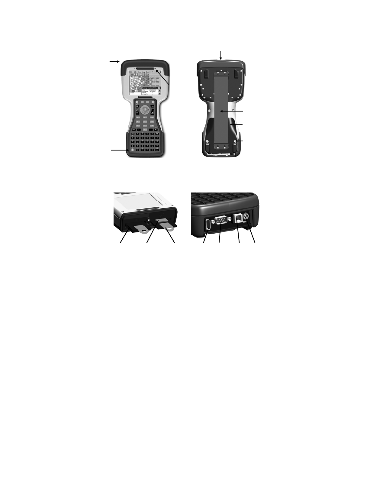
Front Panel Back Panel
Removable CF-Cap covers two
CompactFlash slots and one SD slot
Stylus
holder
Notification
LED
CF-Cap
Power
Hand strap
PowerBoot
Module
PowerBoot
coin screws
Top View- without Cap Bottom View
CompactFlash and SD card slots
CF slot #1
type I
SD
NOTE: Be sure to read the warranty and safety information in this
manual prior to using your unit.
CF slot #2
type I & II
USB
host
Serial
port
USB
client
External
power
2
Page 3
Unit Set Up
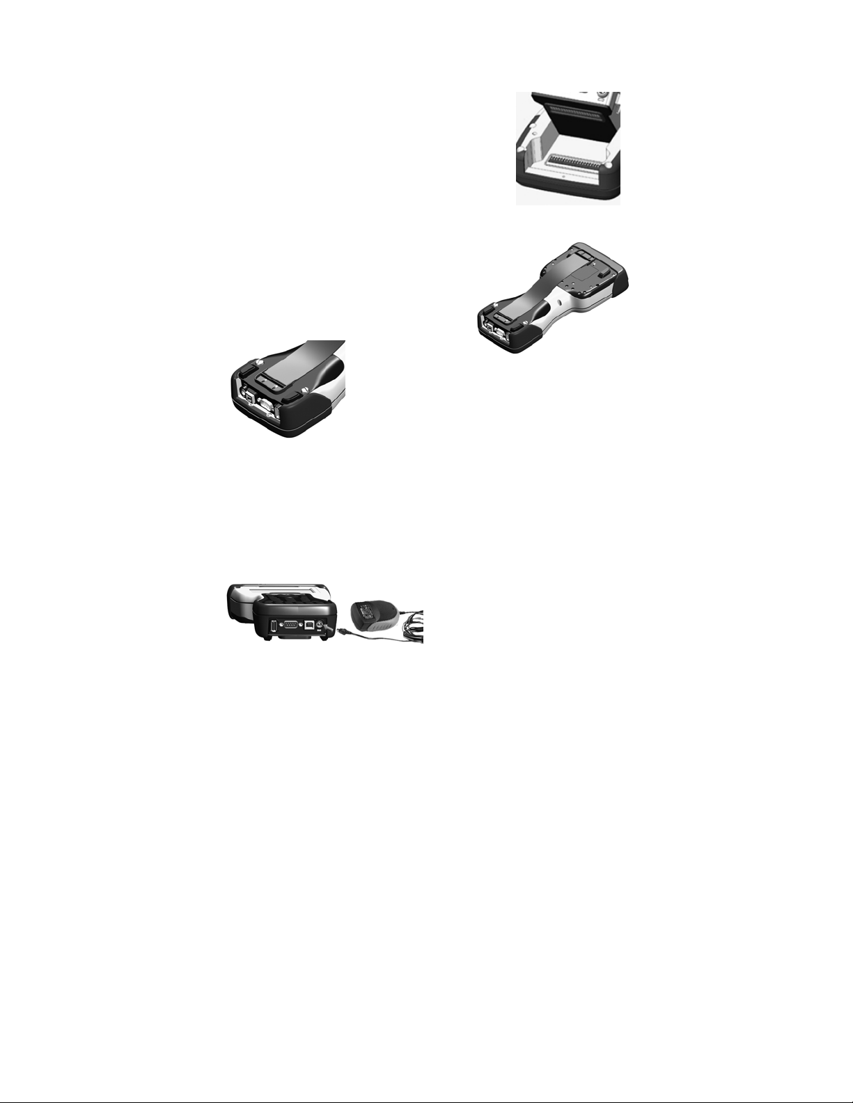
1. Attach the PowerBoot Module
The PowerBoot ModuleTM that contains the
batteries is shipped detached from the unit.
Align the PowerBoot Module with the contacts
facing down. Insert the top end of the
PowerBoot Module first as shown, and then
drop the PowerBoot Module into the unit.
Secure by tightening the two screws with the
stylus, a coin, or a screwdriver.
2. Attach the hand strap
Insert the strap as shown onto the two
small bolts located on the back of the
unit, near the bottom of the PowerBoot
Module.
Now stretch the hand strap and insert the
other end of the strap onto the two bolts at the
top of the unit.
3. Charge your unit
The AC charger that ships with your unit comes with adapters to fit
almost every electrical outlet and voltage. Connect the correct
adapter to the charger, plug the charger into an electrical outlet and
plug the DC jack barrel end of the charger into the external power
port on the PowerBoot Module. Charge the PowerBoot Module for
approximately 4.5 hours.
Warning! Be sure to always use
the charger included with your
unit. Use of other chargers will
void your warranty.
3
Page 4
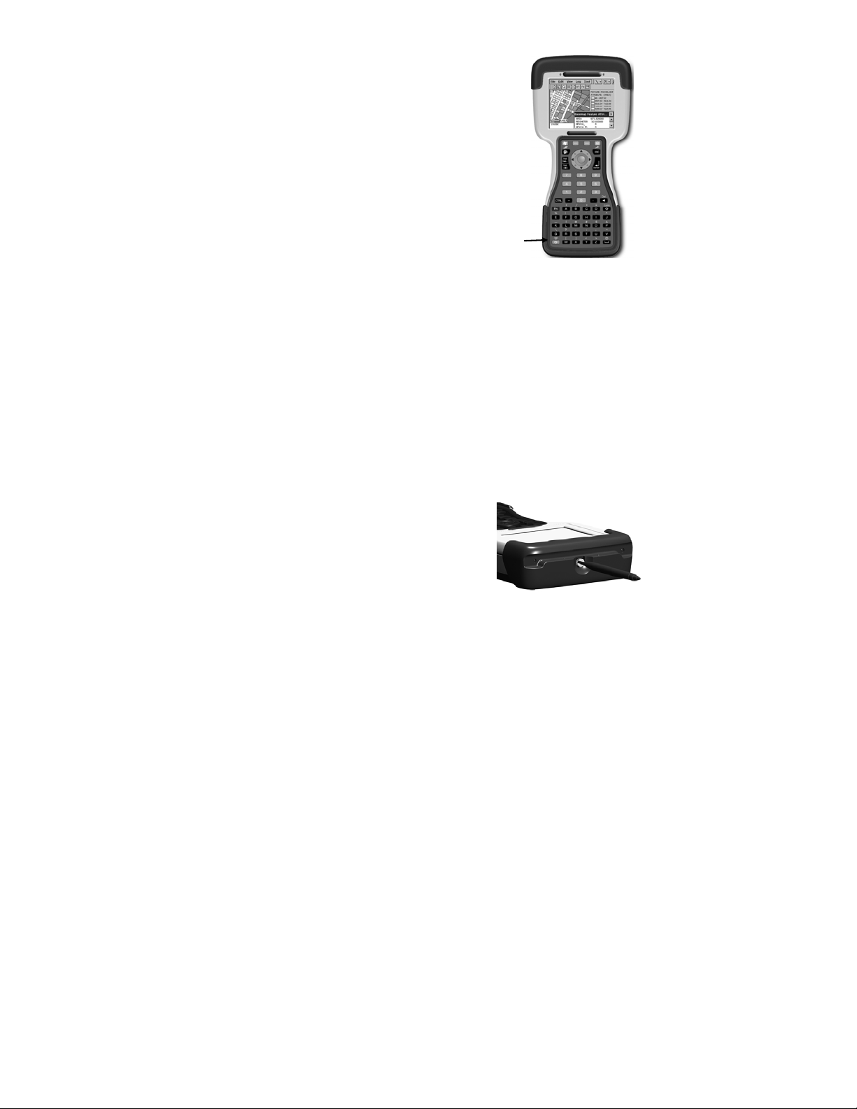
4. Turning your unit on and off
To turn your computer on, press the green Power
key on the lower left hand corner of the keypad.
To turn the computer off, press the Power key
again.
One of the most convenient features of the unit
is “instant on” and “instant off” that happens
every time the Power key is pressed. Also
known as “suspend/resume”, it means that there
is no waiting for the computer to boot up every
time the unit is turned on. “Instant on” does not
occur on the first boot-up.
Power
5. Align the touchscreen
When the unit first turns on (or after a hard reset) the touchscreen
may require alignment. A series of targets is displayed in sequence
on the screen. Use the stylus to tap the targets firmly and accurately
to align the touchscreen. Sometimes it is necessary to repeat the
alignment procedure more than once to provide a satisfactory
calibration.
6. Using the CF and SD expansion slots
Your unit contains two CompactFlash (CF) slots and one Secure
Digital (SD) expansion slot. The SD slot is located within the walls
of one of the CF slots. The SD slot is for memory cards only. SDIO
devices such as cameras or GPS receivers will not operate in this
slot.
To access the CF and SD expansion slots,
remove the CF-Cap
the screw on the top of the CF-Cap using
the stylus, a coin or a screwdriver as
shown, and slide the cap off the main unit.
NOTE: When using smaller CF cards (such as memory or
Bluetooth), it is critical that you attach a CF Card Pull Tab to the
CF card before sliding the card into the slot. A Pull Tab will allow
you to easily remove the CF card from the slot. Pull Tabs are part of
the accessories included with your unit.
4
TM
. To do this, unscrew
Page 5

yp
yp
With the CF-Cap removed, the 2 CF and 1 SD expansion slots are
visible. The CF slots are side by side, and the SD slot can be seen
inside the CF slot #2 cavity.
To insert a CF or SD card:
- CF cards must be inserted with the
front of the card facing toward the
display side of the unit. CF slot #1
supports Type I cards. CF slot #2
supports Type I and II cards.
- SD cards must be inserted with the
front of the card facing away from
the display.
CF Slot #1
e I
T
SD
CF Slot #2
e I & II
T
- Again, be sure to attach a Pull Tab to the smaller CF cards
(such as memory or Bluetooth) before sliding the cards into the
slots.
- Gently insert the CF card or SD memory card into one of the
two CF slots. Do not force the card into the slot. The pins can
be damaged if the card is not aligned correctly.
When replacing the CF-Cap, first be sure it is oriented correctly.
The stylus holder in the CF-Cap is towards the front of the unit.
Replace the CF-Cap and tighten the screw to reseal. The cap should
be securely tightened, but do not over-tighten the screw.
NOTE: Be sure to correctly orient the CF-Cap when you are
reattaching it. The unit is NOT sealed when the cap is off or
attached backwards. Water damage caused by improper installation
of the CF-Cap is not covered by warranty.
5
Page 6

Working with Your Unit
Using the stylus
The touchscreen on your unit works like a mouse on a PC. Use the
stylus to navigate and select objects on the screen.
Tap: Tap the screen with the stylus to select or open an item.
Tapping is equivalent to clicking an item with the left mouse on
your PC.
Touch and hold: When you touch and hold, a circle of blue dots
appears around the stylus to indicate that a pop-up menu will soon
appear. Touching and holding is equivalent to right-clicking your
PC mouse button.
Drag: Hold the stylus on the screen and drag across the screen to
select text and images. Drag in a list to select multiple items.
PowerBoot Module
The PowerBoot Module includes the batteries to power the unit, the
power port used to charge the unit, and the I/O ports that are used to
communicate with other devices (such as a PC) using a USB or
serial cable.
Battery life: Battery life is very dependent upon the application and
operating environment. You can expect about 30 hours of battery
life. Typical usage includes using the unit in moderate or high
outside temperatures without using the backlight, and using low
power CF and SD cards, such as memory cards.
Cold temperatures, heavy use of the backlight and the use of high
power consumption CF cards (such as GPS) will all significantly
reduce the battery life.
Tips for extending the battery life:
- Use the backlight only when necessary. Use the Fn +
keys to toggle the backlight on and off. Tap
Backlight
on when the unit is idle.
6
to minimize the amount of time the backlight stays
Settings / System /
Power
Page 7
- Use the most energy efficient CF cards that are available for
your application and use them only when necessary to perform
the desired task.
- Use the embedded wireless capability (Bluetooth or wLAN)
only when necessary. Turn off (turn Flight Mode on) when not
in use.
- When working in cold temperatures, keep the unit as warm as
possible. If feasible, keep the unit inside your coat or in a
vehicle when not in use.
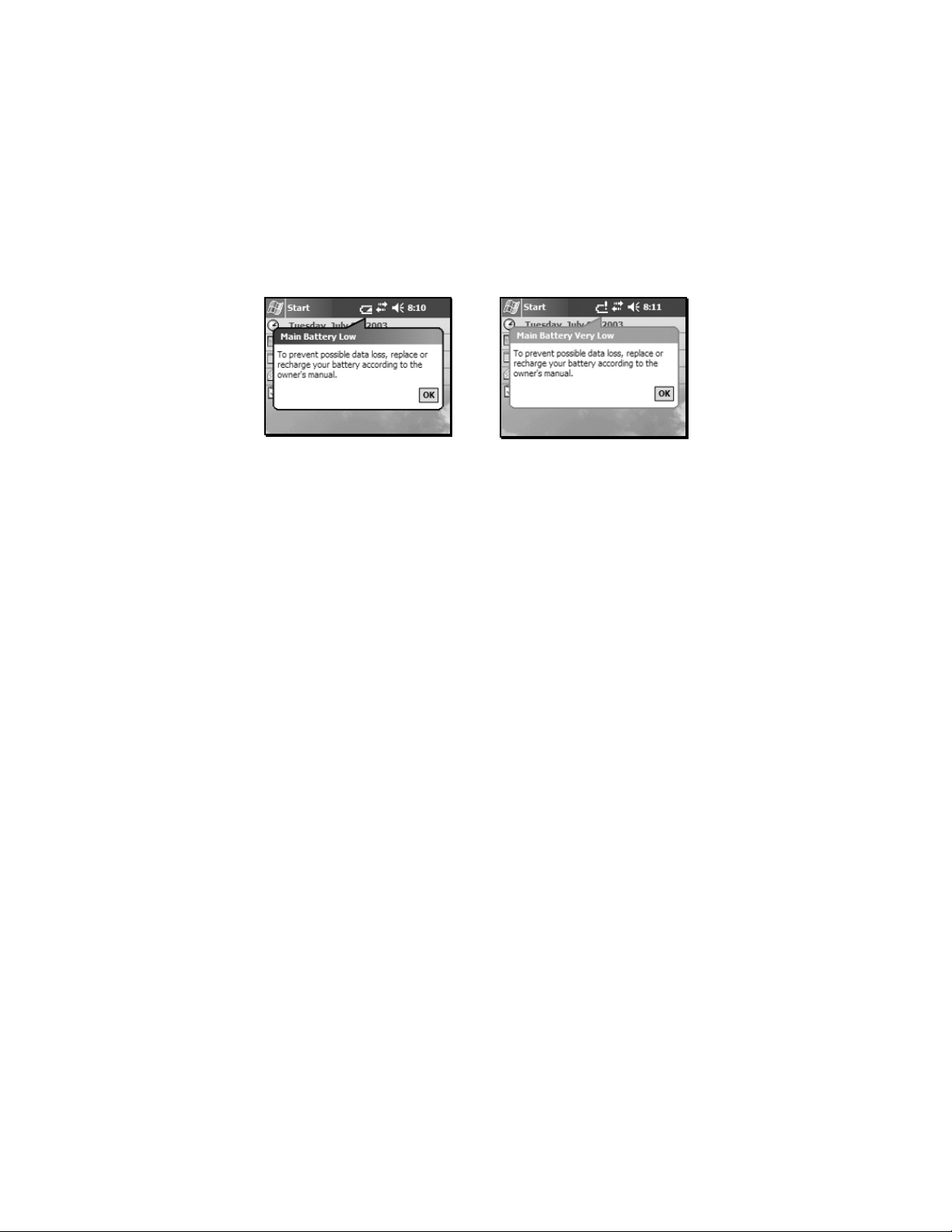
Battery warnings: There are two different warnings that will
indicate when the battery life is getting low:
Low battery warning Critical battery warning
The Main Battery Low warning notifies you when your battery
level reaches a low level and needs to be recharged. You have only
5% or less of your battery life remaining, so start saving your data
as soon as possible.
The Main Battery Very Low warning indicates that the battery level
is at a critically low level and you may have only minutes before the
unit shuts itself off. Save your work immediately and turn the unit
off.
NOTE: Be aware that the accuracy of the battery warnings will
vary depending upon temperature, power consumption, and
applications. Experimentation with your particular situation will
give you a better feel for how the warnings correspond to actual
remaining battery life.
7
Page 8

If the battery level gets too low, the unit will go into an emergency
suspend and will turn itself off. Either charge the PowerBoot
Module or swap it out with a fully-c harged PowerBoot.
Charging the batteries: The PowerBoot Module can be charged
either in or out of the unit.
The AC charger comes with adapters that will fit most electrical
outlets worldwide. Attach the appropriate adapter that fits your
electrical outlets to the charger. To charge the battery, plug the AC
charger into the wall socket. Insert the DC jack barrel connector
into the power port on the PowerBoot Module. The unit will be
fully charged in approximately 4.5 hours. The acceptable
temperature range for charging the battery is between +5°C and
+35°C (+41°F and +95°F).
The PowerBoot Module also has an LED that provides an indication
of charging status. The LED states are shown in the following table.
Normal usage:
Off No charger present, or charger
unplugged.
Fast blink Fast charge.
Slow blink Topoff charge.
On Charging complete.
Error conditions:
One short flash Battery temperature too cold to charge.
Two short flashes Battery temperature too hot to charge.
Three short flashes Wrong charger.
NOTE: When the unit is finished charging and is still connected to
the AC charger, the status found in Settings / System / Power will
report the battery power remaining as if it is still on battery power.
Swapping the PowerBoot Module: The PowerBoot Module is
designed to be quickly swapped in the field. If the current
PowerBoot Module runs low on power, replace the Module and
8
Page 9

continue with your work. (This assumes that you have purchased
additional PowerBoot Modules.)
When turned off, the unit saves enough power that you can swap the
battery without triggering a hard reset if you can swap in the new
PowerBoot Module within a couple of minutes. If the saved power
runs out before the new PowerBoot is connected, the unit will
perform a hard reset when the PowerBoot Module is reattached. All
data, configuration, drivers and settings not saved in Built-in
Storage or on a flash memory card will be lost. Therefore, it is
strongly recommended that you perform a Sprite Backup before
swapping the PowerBoot Module. See the Backup and Restore
section for more information.
To change a PowerBoot Module, perform the following steps:
1. Back up your data to Built-in Storage using the pre-installed
Sprite Backup program. (See information on Backup and
Restore).
2. Press the Power key and turn the unit on. (The unit will
automatically turn itself off when you loosen the screws in step
4.)
3. Remove the hand strap from the unit.
4. Using a screwdriver, a coin, or the flat head of the stylus,
unlock the 2 screws on the PowerBoot Module by turning them
counter-clockwise until the PowerBoot can be removed.
Unscrewing the screws turns the unit off and puts it in a special
state that prevents it from turning on during alarms and
notifications.
5. Remove the PowerBoot Module by taking it out of the unit.
6. Quickly insert the new PowerBoot Module onto the unit.
7. Screw the PowerBoot Module securely into place by turning
the 2 screws clockwise until they are fastened.
8. Replace the hand strap.
9. Press the Power key and turn the unit on.
NOTE: The screws MUST be tightened before turning the unit on
or data could be lost.
9
Page 10

Memory and Built-in Storage
The memory in the unit is used to store software applications,
configuration information, drivers and data. The unit ha s two kinds
of memory, flash and RAM. Flash memory is generally known as
Built-in Storage.
Built-in Storage memory is nonvolatile storage. The contents are
unaffected if the battery is removed or discharged. Therefore, you
should keep your data and software application programs in Built-in
Storage. The amount of Built-in Storage in your unit will vary
depending on your unit configuration. Windows Mobile™ 2003
software for Pocket PC’s uses approximately 26 MB of Built-in
Storage. The balance is available for your use. Third-party CF or
SD memory cards can be used to increase the amount of available
storage memory. They work the same as Built-in Storage, except
they are removable.
RAM is volatile. This means the contents will be lost if the battery
is disconnected or discharged. RAM memory is used to run
programs and is often used as the initial storage area for data. The
amount of RAM in your unit will vary depending on your unit
configuration. Approximately 18 MB is reserved for the operating
system. To save RAM memory contents into Built-in Storage, use
the pre-installed Sprite Backup program. See the next section
"Backup and Restore" for more details about backing up data to
memory. Any data in RAM that is not stored to Built-in Storage wil l
be lost if the battery is removed or discharged. We strongly
recommend regularly saving your data.
The following illustration shows the different kinds of memory as
they appear within File Explorer (Start / Programs / File
Explorer). The nonvolatile Built-in Storage is shown under the top
level My Device at the top of the list
change folders.
10
. Tap on the desired folder to
Page 11
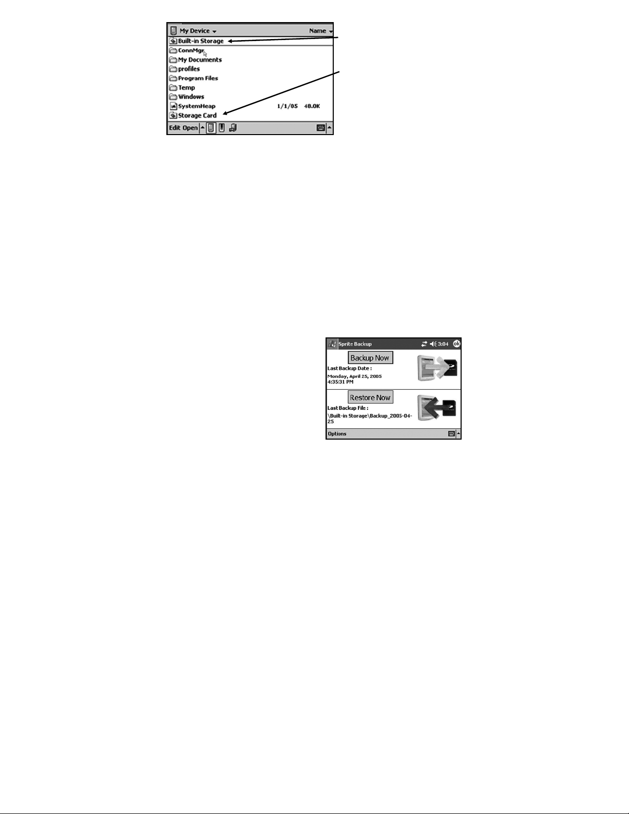
Built-in Storage: The contents
are found in this folder in File
Explorer.
Storage Cards: If memory cards
are present, the contents are
found in these folders in File
Explorer.
RAM: All other files and folders
displayed by File Explorer are
stored in RAM and will need to be
backed up.
Backup and Restore
Many programs and unit configurations reside in RAM and
collected data is sometimes stored in RAM. RAM memory is
volatile and all data and programs residing in RAM will be lost if
the battery is disconnected during use or is completely discharged.
To prevent such data loss, it is important to regularly back up the
RAM to Built-in Storage. Your device comes with a pre-installed
backup utility program called Sprite Backup.
Sprite Backup: Sprite Backup is an easy-to-use program that backs
up data from RAM to the Built-in Storage memory. To run a
backup, tap Start / Programs / Sprite Backup.
Once the program loads, tap
Backup Now and the backup
process will begin immediately.
When the backup is complete a
chime will sound and the screen
will show Operation Complete.
When this occurs, tap OK. This
will bring up a message box once
again telling you that the
operation has completed. Tap OK to restart (soft reboot) your
system. Your backup is now complete. All programs and data are
stored in a backup file and stored in Built-in Storage.
11
Page 12

We recommend that you run Sprite Backup often to ensure that you
never lose any data due to an unforeseen hard reset. Because it’s
easy to forget to do, Sprite Backup offers scheduling automatic
backups as an advanced feature. To set this up, tap Start /
Programs / Sprite Backup. In the lower left corner tap Options /
Switch to Advanced Mode. Next, access the scheduling page by
tapping Options / Scheduled Backup / Change Scheduling. Here
you can set single, daily, or weekly automatic backups to run at a
particular time. Select the desired frequency and the backup time
and tap OK to set the schedule.
NOTE: While scheduled automatic backups will help protect you
from data loss, even a daily restore may not be enough in an
intensive work environment. When collecting a lot of data,
remember to backup often. If a hard reset occurs, any data collected
between the last backup and the hard reset will be lost.
If you experience a hard reset for any reason, you can easily restore
your data from your last backup. After a hard reset, the unit will
automatically prompt you to do a restore. To run restore manually,
tap Start / Programs / Sprite Backup / Restore Now. Once the
restore is complete, you will be prompted to do a soft reset. After
the reset, the unit is restored to its pre-hard reset state.
Power key features
The Power key turns the unit on and off and performs a number of
additional functions.
Turn backlight on/off:
and then the
off until it is toggled back on. Screen taps and key presses will not
cause it to turn on.
Power menu:
display a countdown. Continuing to press the Power key will cause
a soft reset when the countdown reaches zero. If you release the
Power key while the countdown is proceeding, you access the
following menu. Tap an option or OK to exit.
12
Power
Hold down the Power key for about 3 seconds to
To toggle the backlight on or off, press Fn
key. Once toggled off, the backlight will stay
Page 13

Clean Touch Screen: Disables the
touchscreen for cleaning. Press the
enter key to re-enable the
touchscreen.
Align Touch Screen: A series of
targets are displayed. Use a stylus
to tap each target in sequence to
align the touchscreen.
Soft Reset: This resets the unit
Hard reset
A hard reset should be used only if a soft reset fails to
:
hardware but does not clear the
contents of RAM. It can be used to
restart a program that has become
unresponsive.
resolve an issue. The contents of RAM are cleared during a hard
reset. If possible, back up your data before doing a hard reset. See
the Backup and Restore section for more information.
To perform a hard reset, press and hold the Power key and the
CTRL key simultaneously for eight to ten seconds. The reset menu
will appear with a countdown warning. (Under certain conditions,
the countdown will not appear.) Continue to hold both keys down.
When the message Booting - - - -> appears, release both keys. If a
backup was previously performed, the unit will prompt you to
restore the most recent backup.
Additional Key Functions
Several screen functions can be initiated from the keypad. Press the
first key indicated followed by the second key to initiate the action.
The following are some of the most commonly used:
Backlight toggle
Caps Lock
Delete
Windows Start
+
+
+
13
Page 14

Calendar
left
Contacts
right
Speaker and microphone
Your unit comes with an integrated speaker and a microphone. The
speaker will allow you to hear a variety of media.
To use the microphone, enter the Notes program by tapping Start /
Programs / Notes. There are two ways to start recording:
1. Tap the cassette icon at the bottom of the screen. Tap the red
circle at the bottom left corner of the screen.
2. Press and hold the Fn key (Function) and then press and hold
the
If using the record button, the unit will continue to record until the
stop button is pressed. If using the keypad to record, the unit will
continue to record until one or both keys are released.
The ideal speaking distance for recording is from 20 to 30 cm (8 to
12 inches). Speak clearly and loudly, but without shouting. The
recorded file will automatically be saved in the folder displayed at
the top of the screen. To change the directory where recorded files
will be saved, tap on the folder icon and navigate to the desired
folder.
key (Escape).
ESC
To play the recorded file, just tap on the desired file from the Notes
program and it will begin to play automatically. To begin another
recording, press Fn and ESC keys again or tap the record symbol
on the screen. You cannot play and record simultaneously; play
back will be disabled during recording.
To change the volume, tap on the speaker icon in the status bar of
the Today screen (see below). You can either change the volume or
mute all sounds coming from the unit.
14
Page 15

p
The Today screen
At the top of the screen are status icons. Tap an icon to view details
or change options. (These icons appear at the top of every screen on
your unit, not only the Today screen.)
When you turn on your unit for the first time each day (or after four
hours of inactivity) the Today screen displays. You can also view it
by tapping Start / Today.
The center of the Today screen provides information that you need
for the day. Tap an item to view or edit details.
Tap to go to
a program.
Tap to view network status and options.
Tap to change volume.
Touch and hold to change time format.
Tap to change owner
information.
Your day at a glance.
Tap to open the
associated program.
Tap to view connection
Tap to create a new item.
status.
The command bar
At the bottom of the screen is the command bar. You can use its
menus and keys to perform tasks in programs. Depending upon
which program you are using, the buttons may vary from those
depicted below.
Tap to select
menu commands.
Tap to select
key commands.
Tap to display the
ut panel.
in
15
Page 16

The Start menu
y
From the Start Menu, you can select Programs, Settings, and Help
topics. To display the Start Menu, from the top of any screen, tap
Start.
Tap to switch to a program that you recently used.
Tap to switch to a program.
Tap to see more programs.
Tap to change device settings.
Tap to see a Help topic for the current screen.
Pop-up menus
You can use pop-up menus to quickly select an action for an item.
To access a pop-up menu, tap and hold the stylus on an item name.
16
Touch and hold to display the
pop-up menu.
Lift the stylus and tap the
ou want.
action
Tap outside the menu to close
it without performing an action.
Page 17

Settings on Your Unit
Tap Start / Settings. You can tap any of the icons on the Personal,
System or Connections tabs to customize the unit settings to your
own preferences. Tap X on the touchscreen or press OK on the
keypad to exit Settings. Here are a few of the settings on the unit
that are worth noting.
Buttons
Tap Personal / Buttons. The Buttons (Keys) setting allows you to
assign several of the keypad buttons to your favorite programs. By
default, these are preset to common applications such as contacts
and calendar. The list of assignable keys is on the left hand side of
the screen with the program that is assigned by default on the right.
Re-assign them by selecting the key you wish to change in section 1
and chose the desired program or action from the pull-down list in
section 2.
Sounds and Notifications
Tap Personal / Sounds & Notifications. In these screens you can
change sound settings related to event notifications, keypad, and
screen activity. For example, by default the unit will sound a chime
to remind you of any scheduled appointments as well as trigger the
Notification LED above the touch screen. If you wish to disable the
sound and use the LED only, remove the check mark from the
Events box.
To change the volume, tap on the speaker icon in the status bar of
the Today screen. You can either change the volume or mute all
sounds coming from the unit.
Input
Tap Personal / Input. You can change settings related to character
input, word completion and capitalization.
Backlight
Tap System / Backlight. Choose the settings in the Battery Power,
External Power and Brightness tabs as needed for your use of the
unit. The display backlight has significant impact on battery life.
17
Page 18

Screen
Tap System / Screen. The orientation can be changed to portrait for
some programs that are not screen aware.
Memory
Tap System / Memory. Closing programs still leaves them resident
in RAM. As more programs are started, available RAM decreases.
If RAM resources become low, you can stop programs and remove
them from RAM. To stop a program, tap the tab Running
Programs. You can stop individual programs or tap Stop All.
Power
Tap System / Power. This screen allows you to view the
approximate battery power remaining. Note that both the Main
battery and Backup battery levels are shown, but only the Main
battery level is significant. Tap the Advanced tab and choo se the
settings for automatically putting the unit into suspend mode when
not in use.
Tap System / Power / Wireless. If your uni t is equipped with either
Bluetooth or wLAN, you can turn the wireless capability on or off
in this screen.
Connecting to Your PC
USB
host
Serial
port
USB
client
External
power
I/O ports
The unit has both USB and 9-pin serial
ports. Connection via USB to
a PC require an A-B USB cable
(included with the unit). Serial
connections require a 9-pin null-modem serial cable (not included
with unit).
NOTE: Be aware that the operat ing
system running on the unit does not
support the USB Host Port. Please
do not try to connect any devices to
this port.
You may also increase your connectivity options with CF cards.
18
Pin 1
Pin 6
Pin 9
Pin 5
Page 19

Communication
The unit is equipped with multiple ways to communicate with other
devices. Many of these ways are described in the following sections
Where noted, your unit may not have that particular feature.
ActiveSync
Microsoft ActiveSync allows you to synchronize information and
copy files between your PC and your unit. ActiveSync is preinstalled on your unit. Before connecting your unit to your PC,
install ActiveSync on your PC from the Windows Mobile 2003
Second Edition Companion CD that was shipped with your unit.
Alternatively, ActiveSync is available as a free download from the
Microsoft web site:
www.microsoft.com/windowsmobile/default.mspx
IMPORTANT: Do not connect the unit to the USB port on your
PC until after you install ActiveSync. If you prematurely connect
the unit to your PC, your PC USB drivers may get into a confused
state and ActiveSync will not connect. If you suspect that something
like this has happened, then uninstall your PC’s ActiveSync, reboot
your PC, reconnect the unit and reinstall ActiveSync.
Launch the ActiveSync installer on the PC. You will see the screen
Set Up Microsoft ActiveSync. Click Next. A screen will appear
asking what folder to install to. We recommend using the default
setting. Click Next.
The Get Connected dialog box
will automatically appear on the
PC. Connect the unit to your PC
using a USB cable. Tap Next.
Wait a few seconds while your
PC recognizes and connects with
your unit.
19
Page 20

Once your unit has connected
with your PC, you will be
presented with the New
Partnership window.
Your unit supports both Standard and Guest partnerships. If you are
simply interested in installing software on your unit, or in
transferring files between your unit and your PC, a Guest
partnership will be sufficient. If you are also interested in
synchronizing the information in Microsoft Outloo k on y our PC
(such as e-mail, contacts, calendar, and time) with the unit, then
choose Standard partnership and click Next. You will be
presented with the Select Synchronization Settings window.
Select the types of information that
you want to synchronize and click
Next. Wait a few moments while
ActiveSync synchronizes the
selected information types with the
unit.
20
Page 21

Once connected over ActiveSync, you will see a window similar to
the ones below on your PC. Click on the Explore icon to view the
file structure on the unit in a way similar to Windows Explorer on
your PC.
Guest Partnership: Standard Partnership:
If you created a Standard
Partnership, the display on your
unit will reflect the information that
was synchronized from the PC.
Tip: Run a system backup after creating a Standard Partnership so
that the partnership and synchronized information survive a power
loss or unexpected hard reset. See the Backup and Restore section
for more information.
Troubleshooting ActiveSync connection problems
1. Confirm that the unit is configured to communicate with the
PC. Choose Start / ActiveSync / Tools / Options / Options.
Confirm that Enable PC sync using this connection is
checked, and that USB default is selected from the dropdown
list.
2. If you are running personal firewall software on the PC, try
disabling it. ActiveSync needs certain TCP/IP ports to be open.
21
Page 22

3. Try soft resetting the unit and rebooting the PC. To soft reset
the unit, hold down the Power button until Booting - - - ->
appears across the bottom of the screen.
4. If you have more than one unit, PC and/or cable, testing
different combinations of equipment can help isolate the cause
of the problem.
5. As noted earlier, if you suspect that the unit may have been
connected to the PC USB port before ActiveSync was
installed, then uninstall ActiveSync, reboot the PC, and
reinstall ActiveSync.
Wireless LAN (802.11b)
Your unit may include embedded 802.11b or wireless LAN
(wLAN) capability. If the configuration of your unit includes
embedded 802.11b, then your unit has the ability to wirelessly
connect to the Internet and other data networks by connecting to
available access points or hot spots. Once connected, you can
browse the Internet or fileshares on the local network.
The wLAN is on by default. To turn wLAN off, tap Start / Settings
/ System / Power, then tap on the Wireless tab and tap Wireless
Signals Off. Turning wLAN off will save battery power and may
speed up other processes so it is recommended that you turn off
wLAN when not in use. There are also some alternative ways to
disable wLAN. You can turn wLAN off and access other wireless
parameters from the Wireless Client application (tap Start /
Programs / Wireless Client). A shortcut way to disable wLAN is
to tap on the radio icon on the status bar and tap Turn on flight
mode.
If the unit detects a wireless network
or hot spot, it will open a window
similar to the one shown:
An Internet connection is one in which Virtual Private Network
(VPN) services are not involved and proxy servers may or may not
22
Page 23

be utilized. This can include a typical Internet connection through a
corporate wireless network. A Work connection allows you to view
fileshares on a corporate network and can also be used to remotely
synchronize with your PC if you have already created an
ActiveSync Standard Partnership.
Select Internet or Work as appropriate, and tap Connect.
Depending upon the configuration of the wireless network, you may
be prompted to enter a Wireless Encryption Protocol (WEP) key for
authentication purposes. Obtain the WEP key from your network
administrator.
Tip: Run a system backup after establishing a wLAN connection so
that the settings survive a power loss or unexpected hard reset. See
the Backup and Restore section for more information.
If you chose to create an Internet connection, open Pocket Internet
Explorer on the unit (Start / Internet Explorer) and browse the
Internet much as you would browse the Internet on a PC. Note that
Pocket Internet Explorer does not support some features that are
supported by desktop PC browsers. For instance, there are no popup windows under Pocket Internet Explorer, and you may be unable
to use web-based e-mail and access other sites on the Internet.
If you chose to create a Work
connection, open File Explorer on
unit. Tap Open to open a window,
allowing you to enter the name of a
computer on the network on which
you want to view fileshares. Tap
OK.
From here, you can browse the
network fileshares and copy and
paste files between PCs on the
network and the unit.
23
Page 24

ActiveSync over an wLAN connection
If you create an ActiveSync Standard Partnership between your unit
and your PC, it is possible to synchronize e-mail and other
information on your unit across the wireless network.
Open ActiveSync on the PC and
choose File / Connection Settings.
Confirm that Allow network
(Ethernet) and Remote Access
Service (RAS) server connection
with this desktop computer is
checked.
Confirm that you have created a
Standard (not Guest) Partnership
between unit and your PC with
ActiveSync. Confirm that the unit is
connected to the wireless network, and that the connection type is
Work, not Internet. Finally, confirm that your PC is connected to
the same network (not necessarily wirelessly).
At this point, provided that you are within range of the wireless
network, you can synchronize the information on your unit with the
information in Outlook on your PC.
On the unit, choose Start /
ActiveSync / Sync. Wait several
moments while the unit connects
to your PC over the wireless
network, and then synchronizes
the information on unit with the
information on the PC.
Troubleshooting wLAN connection problems
1. Confirm that the unit has an appropriate IP address. On the
unit, choose Start / Programs / Wireless Client / Advanced /
Network Troubleshooting to view the unit’s IP address.
24
Page 25

Confirm that the IP address is appropriate for the network to
which you are trying to connect (for instance, 10.0.x.x or
192.168.x.x). Consult with your network administrator to
confirm what appropriate IP addresses look like for your
network. By default, the unit obtains an IP address from a
DHCP server. If your network uses static IP addresses, then
choose Start / Settings / Connections / Network Cards /
Network Adapters / Wireless B Network Driver. Enable the
Use specific IP address and enter the appropriate IP address.
2. If your unit has an appropriate IP address, confirm whether
you can ping another computer on the network. On unit,
choose Start / Programs / Wireless Client / Advanced /
Network Troubleshooting. Enter either the IP address or the
name of another PC on the network, and tap Contact.
3. If the unit seems to be connected to the network, but you are
having difficulty using the network connection, choose Start /
Settings / Connections / Network Cards / Network
Adapters, and confirm that the connection is appropriately
configured as either a Work or Internet connection.
Bluetooth
Bluetooth is a short-range (about 10 meters or 30 feet) radio
technology that allows Bluetooth-enabled devices in close
proximity to communicate with each other without using cables. If
your unit is equipped with embedded Bluetooth capability, then you
can use Bluetooth to replace operations formerly requiring cables.
Bluetooth on the unit is disabled by default. To enable Bluetooth on
the unit, choose Start / Settings / Connections / Bluetooth. Check
the box Turn on Bluetooth. If you want other Bluetooth devices to
be able to find your unit, also check the box Make this device
discoverable to other devices.
Tip: After configuring your Bluetooth connections, turn Bluetooth
discovery off on the unit. This will improve your unit’s security,
and will slightly improve your unit’s battery life.
The details of configuring Bluetooth connections vary depending
upon how the other Bluetooth device works. Several examples (unit
25
Page 26

to unit; unit to/from a PC) are discussed in the following sections.
Note that you cannot use Bluetooth to create an ActiveSync
connection between the unit and your PC. ActiveSync Bluetooth
connections are not supported.
Bluetooth file transfer between two units
It is possible to transfer files from one unit to another over a
Bluetooth connection. Choose Start / Settings / Connections /
Bluetooth, and confirm that Bluetooth is enabled on both units.
Confirm that the unit that will receive the file is discoverable.
Launch File Explorer on the unit that will send the file. Browse to
the file to be sent, and touch and hold on it. Choose “Beam File”
from the menu that appears. Wait for several moments while the
sending unit searches for Bluetooth devices in the vicinity.
Select the receiving unit from the
list, and tap Tap to send. Wait for a
few moments while the file is
transferred. The receiving unit will
open a window asking whether you
want to accept the file. Choose Yes.
The file will be saved in the My
Documents folder on the unit.
Bluetooth file transfer from a unit to a PC
It is possible to transfer files from a unit to a Bluetooth-enabled PC
over a Bluetooth connection. These instructions are based on a PC
running the Windows XP operating system with Service Pack 2 and
a USB Bluetooth dongle. The native Microsoft Bluetooth support is
used; there are no drivers installed for the dongle.
On the unit, choose Start / Settings / Connections / Bluetooth, and
confirm that Bluetooth is enabled. It is not necessary for the unit to
be discoverable.
26
Page 27

On the PC, right click on the
Bluetooth icon in the system tray and
choose Open Bluetooth Settings /
Options. Confirm that the PC is
discoverable and connectable.
On the PC, right click on the
Bluetooth icon in the system tray and
choose Receive a File. A Bluetooth
File Transfer Wizard will open on the
PC and indicate that it is waiting to
receive a file.
Launch File Explorer on the unit that will send the file. Browse to
the file to be sent, and touch and hold on it. Choose Beam File from
the menu that appears. Wait for several moments while the sending
unit searches for Bluetooth devices in the vicinity.
Select the PC from the list of Bluetooth devices and tap Tap to
Send. Wait for a few moments while the file is transferred. The
Bluetooth File Transfer Wizard on the PC will ask you to confirm
that you want to accept the file and will allow you to browse to a
suitable location to save the file.
Bluetooth file transfer from a PC to a unit
It is possible to transfer files from a Bluetooth-enabled PC to a unit
over a Bluetooth connection. These instructions are based on a PC
running the Windows XP operating system with Service Pack 2 and
a USB Bluetooth dongle. The native Microsoft Bluetooth support is
used; there are no drivers installed for the dongle.
On the unit, choose Start / Settings / Connections / Bluetooth.
Confirm that Bluetooth is enabled and that the unit is discoverable.
On the PC, right click on the Bluetooth icon in the lower right
corner of the Today screen. Choose Send a File to launch the
Bluetooth File Transfer Wizard on the PC. Tap Browse to allow the
PC to search for Bluetooth devices in the vicinity. Select the unit
27
Page 28

from the list of devices and choose OK. Proceed through the
Bluetooth File Transfer Wizard on the PC to transfer the file. Wait a
few moments while the file is transferred.
The unit will open a window to confirm that you want to accept the
file. Choose Yes. The file will be saved in the My Documents folder
on the unit.
Troubleshooting Bluetooth connection problems
If your unit cannot find another Bluetooth device, confirm that the
device is within range (less than 10 meters / 30 feet) of other
Bluetooth-enabled devices. Also confirm that the device is turned
on and has been configured to be discoverable. Bluetooth devices
such as printers and cell phones are typically not discoverable by
default.
Additional connectivity
The unit supports several kinds of connections in addition to
ActiveSync, embedded Bluetooth and wLAN. If you do not have
embedded Bluetooth or wLAN, you can purchase a CF card to get
the functionality. In addition to Bluetooth and wLAN, the following
types of connectivity are also possible:
Modem: The unit supports dial-up connections to an Internet
Service Provider and sending and receiving e-mail with file
attachments. (You will need to purchase an external modem or a CF
modem.)
Web-enabled cell phones: The unit can connect to the Internet via
Bluetooth and web-enabled cell phones that are compatible with
Pocket PC devices. USB phones are not supported. Refer to your
phone service provider for more information on establishing
Internet connections via your cell phon e.
VPN: The unit includes support for Virtual Private Network (VPN)
connections. Used together with a connection to the Internet, a VPN
connection allows you to browse network files from a remote site
and also supports remote synchronization with your PC via
28
Page 29

ActiveSync. Note that the network you access must be configured to
allow VPN connections.
For more information on creating these connections, see the web
site listed under reference materials on the last page of this manual.
Installing additional software on your unit
The unit can run third-party software designed for Microsoft
Windows Mobile 2003 Second Edition Pocket PC devices.
However, not all Windows Mobile third-party programs are screen
rotation aware and therefore may not run properly in a landscape
environment. The screen orientation can be changed in Settings /
System / Screen that will allow these programs to run correctly.
Most third-party software is installed by running a setup program on
the PC while the unit is connected with ActiveSync. If prompted by
the installation wizard, perform a soft reset to complete the
installation.
NOTE: Follow the setup instructions that came with your software.
Caring for Your Unit
Cleaning the unit
Clean the unit with a soft cloth dampened with either water or a
diluted mild detergent. Do not use any chemical cleaners and do
not put the unit in the dishwasher.
Mechanical shock
The unit is designed to resist damage for drops up to 1.22 meters
(4.0 ft). However, you should protect the display from impact,
pressure, or abrasive substances that can scratch it or crack it. The
unit should not be dropped unnecessarily
.
29
Page 30

Care of the touchscreen
Use only the included stylus or other devices specifically designed
for use with touchscreens. The use of ballpoint pens, sticks, nails or
other sharp objects to operate the touchscreen will scratch and/or
damage the unit. Abrasives may scratch touchscreens. Keep the
touchscreen clean by gently wiping the display, using a soft clot h
dampened either with clean water or glass cleaner. Do not apply
any cleaner directly to the display. Do not use any abrasive
cleaners.
Use the screen protectors included with the unit to keep the
touchscreen clean and protected. To apply a screen protector, first
clean the display thoroughly. Peel the backing from the screen
protector. Align the edge, and then drop the remainder onto the
display. Use a credit card, if necessary, to squeegee the air from
underneath the screen protector.
Care of the PowerBoot Module
The PowerBoot Module contains rechargeable Lithium Ion (Li-Ion)
cells that power the unit.
Charging guidelines:
• It is not possible to overcharge the batteries. They are self-
regulated. You may leave them on charge indefinitely with no
adverse consequences to their service life.
• Use only the charger supplied with your unit. Use of other
chargers may void your warranty.
• The acceptable temperature range for charging the battery is
between +5°C and +35°C (+41°F and +95°F). This is based on
the internal battery temperature that may be different than the
ambient temperature. If the battery detects a temperature too
high or too low for charging, the LED will flash a warning
sequence. The PowerBoot Module will defer charging until it
detects appropriate temperatures.
30
Page 31

Storage guidelines:
• If you have a spare PowerBoot Module that is not in use, do
not store it in a place where temperatures exce ed room
temperature for long periods (like the glove box of a vehicle in
warm climates). Long-term storage at very warm temperatures
(over +35°C / +95°F) will reduce service life and will
accelerate the normally very slow loss of charge capacity.
• For prolonged storage situations, store the PowerBoot Module
at approximately 50% charge level.
• Do not store the PowerBoot Module with loose metal parts
(like keys in your pocket) that might short the terminals. This
could result in high currents and dangerously high
temperatures.
Environmental Considerations
The unit’s rugged design allows you to run your Pocket PC
applications in harsh outdoor environments. Here are some
considerations that will help you get the most out of your unit when
working in very wet, hot or cold conditions.
Water
This handheld computer is designed to withstand accidental
immersion. To maintain the unit’s water resistant seal, it is
important to ensure that the CF-Cap is correctly oriented with the
stylus holder facing the front of the unit, and that the screw on the
CF-Cap is tightened but not over-tightened. Failure to reattach the
CF-Cap screw could cause leakage and will void your warranty.
Because the PowerBoot Module is designed to easily disconnect
from the unit, water can occasionally find its way onto the metal
contacts between the battery and the unit. After working in very wet
conditions remove the battery and check the contacts to see if they
are wet. If so, dry the contacts on both the unit and the battery with
a tissue, paper towel or clean cloth before storing the unit for
overnight or longer.
31
Page 32

Temperature range
The operational temperature range is from -30°C to +60°C (-22°F to
+140° F). In addition, the unit can be stored at temperatures from
-40°C to +70°C (-40°F to +158°F). Although the unit is designed to
be rugged, do not leave it in direct sunlight or in a parked vehicle in
the sunlight for extended periods.
Batteries perform best at room temperatures. The unit battery pack
also has a very stable capacity as temperature rises above the human
comfort level. However, cold temperatures cause battery life to
drop, and the colder the temperature the greater the reduction in
available battery life. Battery life reduction will also depend upon
other usage conditions, including backlight status, CPU load,
embedded wireless status and the use of power consuming CF
devices. Under very cold conditions (-20°C / -4°F and below), you
can expect your battery life to be shortened by anywhere from 30 to
70 percent.
If you anticipate working under very cold conditions, consider
carrying a fully charged, spare battery in a warm place. The unit is
designed to make battery replacement a simple process. Anything
that you can do to keep the unit and the spare battery warm (for
instance, keeping it in a pocket under your coat) will improve your
battery performance.
At moderate temperatures, you can expect your battery to last about
full charge/discharge cycles before its performance noticeably
300
declines.
32
Page 33

Hardware Specifications
OS Windows Mobile for Pocket PC 2003 Second
Edition
CPU Intel® PXA 270 XScale CPU
RAM (VOLATILE) 64 or 128 MB SDRAM
ROM (NONVOLATILE) 256 or 512 MB of NAND Flash
DISPLAY Landscape 3.8” Color ¼ VGA display, sunlight
readable, backlit
BATTERY LIFE 30 hours continuous room temperature
operation with default settings and no backlight
BATTERY CHARGING ~4.5 hours to full charge; 80% charge in 2
hours
BATTERY CAPACITY 6600 mAh Lithium-Ion
I/O PORTS Power, RS-232 serial (9-pin), USB client
SOUND Integrated sealed speaker and microphone
EXPANSION PORTS 2 CF slots 1xType I and 1xType II, 1 SD slot
ENVIRONMENTAL Submersible, drop-resistant, dust-proof (see
Environmental section)
INTEGRATED
CAPABILITIES
Optional Integrated Bluetooth and wLAN
(802.11b) capability
Environmental Specifications
TEMPERATURE Operation: -30°C to +60°C (-22°F to +140°F)
Storage: -40°C to +70°C (-40°F to +158°F)
WATER Submersible to 1 meter for 30 minutes, IP67,
MIL-STD 810F, Method 512.4, Procedure 1
DROP 1.22 m (4.0 ft.) onto concrete
SAND AND DUST Sealed against dust, IP67, MIL-STD 810F,
Method 510.4, Procedures I and II
VIBRATION Mil-STD 810F Method 514.5
ALTITUDE To 4572 m (15,000 ft) at a nominal
temperature of +23°C (+73°F)
Mil-STD 810F Method 500.4, Procedures I, II,
& III
EMI Meets FCC class B requirements
33
Page 34

Safe Use of Your Unit
Carrying the unit
Due to radio frequency emissions, it is unsafe to operate the radio
with the unit in a holster, dangling from a lanyard, or with any
method that keeps the powered unit in very close proximity to the
head or torso. For safe operation, carry the unit in your hand with
the antennas located at least 20 cm (~8 inches) from the head or
torso. See the following illustration for the correct and incorrect
way to operate the unit.
Correct Incorrect
Repair
Please do not attempt to dismantle the unit for repair. There are no
user-serviceable parts inside. For service, please use the contact
details listed on the last page of this manual or your local dealer.
Battery safety
• Use only the battery supplied with your unit to power the unit.
Use of other power sources could damage the unit, void your
warranty and pose safety hazards.
• Caution: Do not attempt to disassemble the battery pack. There
are no user serviceable parts in the battery pack. If it is defective
return it to the manufacturer for service. Disassembly or
modification of the pack could pose safety hazards of burn, fire
and exposure to harmful chemicals.
• Handle a damaged or leaking battery with extreme care. If the
electrolyte comes in contact with your skin, wash the exposed
area with soap and water. If it comes in contact with the eye, flush
the eye with water for 15 minutes and seek medical attention.
34
Page 35

• Lithium Ion batteries are classified by the U. S. federal
government as non-hazardous waste and are safe for disposal in
the normal municipal waste stream. These batteries, however, do
contain recyclable materials and are accepted for recycling.
Environmental hazards
The unit contains no mercury or cadmium.
AC charger safety
• Use only AC chargers intended for the unit. Other external power
sources may damage your product and may void the warranty.
• Make certain that the input voltage on the charger matches the
voltage in your location.
• Make certain that the charger has prongs compatible with your
outlets.
• AC chargers are designed for indoor use only. Avoid using the AC
charger in wet areas.
• Unplug the AC charger from power when not in use.
• Do not short out the output connector.
Troubleshooting and FAQ’s
How do I delete files?
Open File Explorer and browse to the file to be deleted. Use the
stylus to touch and hold on the file, and then choose Delete from the
menu that appears.
How can I enable caps lock?
press Fn key (to the left of the “A” button), and then the up arrow
key (to the right of the “D” button) to toggle caps lock.
Where is the Recycle Bin?
Unlike desktop PCs, the Windows Mobile 2003 operating system
does not support a Recycle Bin. Once you delete a file, it is gone for
good, so be very careful.
Is there anything I can do to make the display more viewable?
35
Page 36

The default backlight brightness is set to about 65 percent of the
maximum brightness. Choose Start / Settings / System / Backlight
/ Brightness, and adjust the slider to increase display brightness;
however, doing this will reduce battery life. Also, confirm that you
have one – and only one! – screen protector in place.
How can I tell how much memory is available?
Choose Start / Settings / System / Memory to view available
RAM. As an example here,
18.11 MB of RAM is available
for applications and 26.92 MB of
RAM is available for files. (The
Windows Mobile operating
system manages the allocation of
Storage Memory and Program
Memory, so moving the slider
bar has only a temporary effect.)
Tap Storage Card to view available memory in the Built-in Storage
area. If a CF or SD memory card is installed, tap on the dropdown
arrow next to Built-in Storage and choose Storage Card.
When I work outside in the sunshine with sunglasses, the screen
is very dark and hard to see. What can I do?
If your sunglasses are polarized, they may be polarized at an angle
incompatible with the display. Try using non-polarized sunglasses
or else try to find sunglasses that have a different polarization
orientation.
I am worried that my battery isn’t performing as well as it
should. Is there any way that I can test it to see whether it’s ok?
The operating system includes a Battery Logger utility to help
evaluate battery performance. To run a battery log, configure the
unit to never go to sleep (Start / Settings / System / Power /
Advanced and uncheck the box under On battery power). Tap
OK. Run the Battery Logger utility (Start / Programs / Battery
Logger). Enter a file name and file location (or use the default), and
36
Page 37

tap Tools / Start Battery Logging. This utility creates a file that
records the battery voltage at intervals. Connect the AC charger to
the unit and charge the unit fully (~4.5 hours). Disconnect external
power and allow the program to run until the battery is exhausted
and the unit shuts down. Reapply AC power and soft reset the unit
to close the power logging utility. Copy the file to the PC, and then
open it in any text editor. Check the time of the first and last entry
in the file to determine how many hours elapsed before the unit
turned off to preserve memory. A healthy battery should run about
30 hours if the backlight is off.
It is critically important that my battery doesn’t fail during a
job. Do you have any suggestions?
Consider carrying a well-charged spare battery in the field. The unit
is designed so that battery replacement can be easily done.
My unit won’t communicate with my PC over an ActiveSync
USB connection.
Make sure that there aren’t any open applications running on the
unit, which may be interfering with communication. One way to
immediately close all open applications is to perform a soft reset
(See the section on Power Button Features).
Choose Start / ActiveSync / Tools / Options / Options, and make
sure that Enable PC sync using this connection is checked and
that USB Default is selected from the dropdown list.
Try disabling any personal firewall software, which is running on
your PC. Firewalls may block TCP/IP from opening ports, which
are required by ActiveSync.
How can I see file extensions or file attributes?
The File Explorer that is included in the Windows Mobile 2003
operating system does not have as many features as the Windows
Explorer program on a desktop PC. There is no support for viewing
file extensions or attributes from within File Explorer.
37
Page 38

There are two ways to get around this limitation: If you connect to
the unit over ActiveSync (refer to the Communication section for
details), you can browse from the PC and view file extensions and
attributes. Alternatively, third party file management programs are
available for Windows Mobile 2003 devices. These third-party
programs may support viewing file extensions, file attributes, zip
archives, and more. Some third-party programs may also support a
Recycle Bin and other useful file management features.
Can I work with Microsoft Office files in Pocket Word and
Pocket Excel?
Microsoft Pocket Word and Pocket Excel are trimmed down
versions of the Microsoft Word and Excel PC applications.
Microsoft Pocket applications allow you to view simple documents
and to make simple changes on your unit. However, Pocket Word
and Pocket Excel do not support all of the formatting and other
features (such as macros) that are supported by the PC applications.
If you use ActiveSync to transfer .doc or .xls files from the PC to
the unit, these files will automatically be converted to .pwd (Pocket
Word) or .pxl (Pocket Excel) files. If you then copy the .pwd or .pxl
files back to the desktop, they will be converted back to .doc or .xls
files, but some formatting and other attributes may be lost.
Can I use my USB memory stick (or mouse, keyboard, cell
phone or other USB device) with my unit?
Not at the present time. USB uses a host/clie nt architec ture, and all
of these devices are clients. The unit is also a USB client, and two
USB clients cannot communicate with each other.
NOTE: The unit does have a physical USB host port on the bottom
of the PowerBoot Module, but it is not currently supported.
Can I use my SDIO device with my unit?
No, the SD port is for memory cards only.
38
Page 39

Regulatory Information
U.S.A.
This device complies with Part 15 of the FCC Rules. Operation is
subject to the following two conditions: (1) this device may not cause
harmful interference, and (2) this device must accept any interference
received, including interference that may cause undesired operation.
This equipment has been tested and found to comply with the limits
for a Class B digital device, pursuant to Part 15 of the FCC Rules.
These limits are designed to provide reasonable protection against
harmful interference in a residential installation. This equipment
generates, uses and can radiate radio frequency energy and, if not
installed and used in accordance with the instructions, may cause
harmful interference to radio communications. However, there is no
guarantee that interference will not occur in a particular installation.
If this equipment does cause harmful interference to radio or
television reception, which can be determined by turning the
equipment off and on, the user is encouraged to try to correct the
interference by one or more of the following measures:
- Reorient or relocate the receiving antenna.
- Increase the separation between the equipment and receive r .
- Connect the equipment into an outlet on a circuit different from
that to which the receiver is connected.
- Consult the dealer or an experienced radio/TV technician for
help.
Canada
This digital apparatus does not exceed the Class B limits for radio noise
emissions from digital apparatus as set out in the radio interference
regulations of the Canadian Department of Communications.
Le présent appareil numérique n’émet pas de bruits radioélectriques
dépassant les limites applicables aux appareils numériques de Classe B
prescrites dans le règlement sur le brouillage radioélectrique édicté par
le Ministère des Communications du Canada.
39
Page 40

Declaration of Conformity
Europe
According to ISO / IEC Guide 22 and EN 450 14
Manufacturer’s Name: Tripod Data Systems, Inc.
Manufacturer’s Address: 345 SW Avery Ave.
Declares, under our sole responsibility, that the product:
Product Name: Field Data Collector
Model Number: Ranger X
Product Options: ALL
conforms to the following Product Specifications:
Safety: EN60950-1:2001
EMC: EN 55022: 1994 +A1, A2: 1997 EN 55022: 1998 +A1:2000
EN 61000-3-2, 1995+A1+A2: 1998
EN 61000-3-2:2000 EN 61000-3-3:1995
EN 61000-3-3:1995+A1:2001 CFR 47, Part 15, Subpart B
EN 55024:1998* EN 55024:1998+A1:2001*
R&TTE Directive 1999/5/EC:
EN 300 328 V1.6.1
EN 301 489-1 V1.4.1
EN 301 489-17 V1.2.1
Supplementary Information:
In addition to meeting the above EMC requirements during system test, the AC
Charger provided with this product has been certified to IEC 60950 +A1, A2,
A3, A4, A11.
* Product is battery powered.
Corvallis, OR USA
Corvallis, OR 97333 USA
CAUTION:
Only approved accessories may be used with this equipment. In general, all
cables must be high quality, shielded, correctly terminated, and normally
restricted to two meters in length. AC chargers approved for this product
employ special provisions to avoid radio interference and should not be altered
or substituted.
Unapproved modifications or operations beyond or in conflict with these
instructions for use may void authorization by the authorities to operate the
equipment.
40
071305
 Loading...