

Page 1

PeopleNet Display.5
™
INSTALLATION GUIDE
TRANSFORMING THE WAY THE WORLD WORKS
Page 2

2
FCC COMPLIANCE
Non-authorized modication could void authority to use this equipment. The internal / external antenna(s) used for this module
must provide a separation distance of at least 20 cm from all persons and must not be co-located or operating in conjunction
with any other antenna or transmitter.
In accordance with 47 CFR § 15.19, the end product into which this module is integrated shall bear the following statement in a
conspicuous location on the device:
This device complies with part 15 of the FCC Rules. Operation is subject to the following two conditions:
1. This device may not cause harmful interference, and
2. This device must accept any interference received, including interference that may cause undesired operation.
Page 3

3
TABLE OF CONTENTS
Important Safety Considerations 4
Part List 5
System Overview 6
Hardware Installation 7
Indicator Lights 13
Initialization Procedure 14
Test Initialization 27
Troubleshooting 28
Page 4

4
IMPORTANT SAFETY CONSIDERATIONS
For ELD compliance, the device needs to be mounted in a xed position during the operation of the commercial
motor vehicle and visible to the driver when the driver is seated in the normal driving position.
Ensure that the location does not interfere with the driver’s operation of the commercial motor vehicle, including
view of gauges, and does not protrude over the dash covering the windshield view.
The mounting plate should be located on an area that is at and can support the weight of the mount arm and the
device.
Page 5
5
Serial No.: PD51000000001Model: PD5
P/N : L019-0156
Input : 12V1A
Contains FCC ID : XPYEMMYW161
Trade Name : PEOPLENET
Importer : PEOPLENET
Manufacturer : PEOPLENET
MN 55344, USA
MN 55344, USA
6807 Shady Oak Road Eden Prairie,
6807 Shady Oak Road Eden Prairie,
Made in China
input : 12V 1A
PART LIST
The following are the parts required for a standard
PeopleNet Display.5 installation
Item Part Number
PeopleNet Display.5 L-019-0516
Cable L-016-0642
RAM Mount H-050-0013
RAM to Vehicle Screw Pack H-048-0510
RAM to PeopleNet Display.5 Screw Pack H-048-0509
Page 6
6
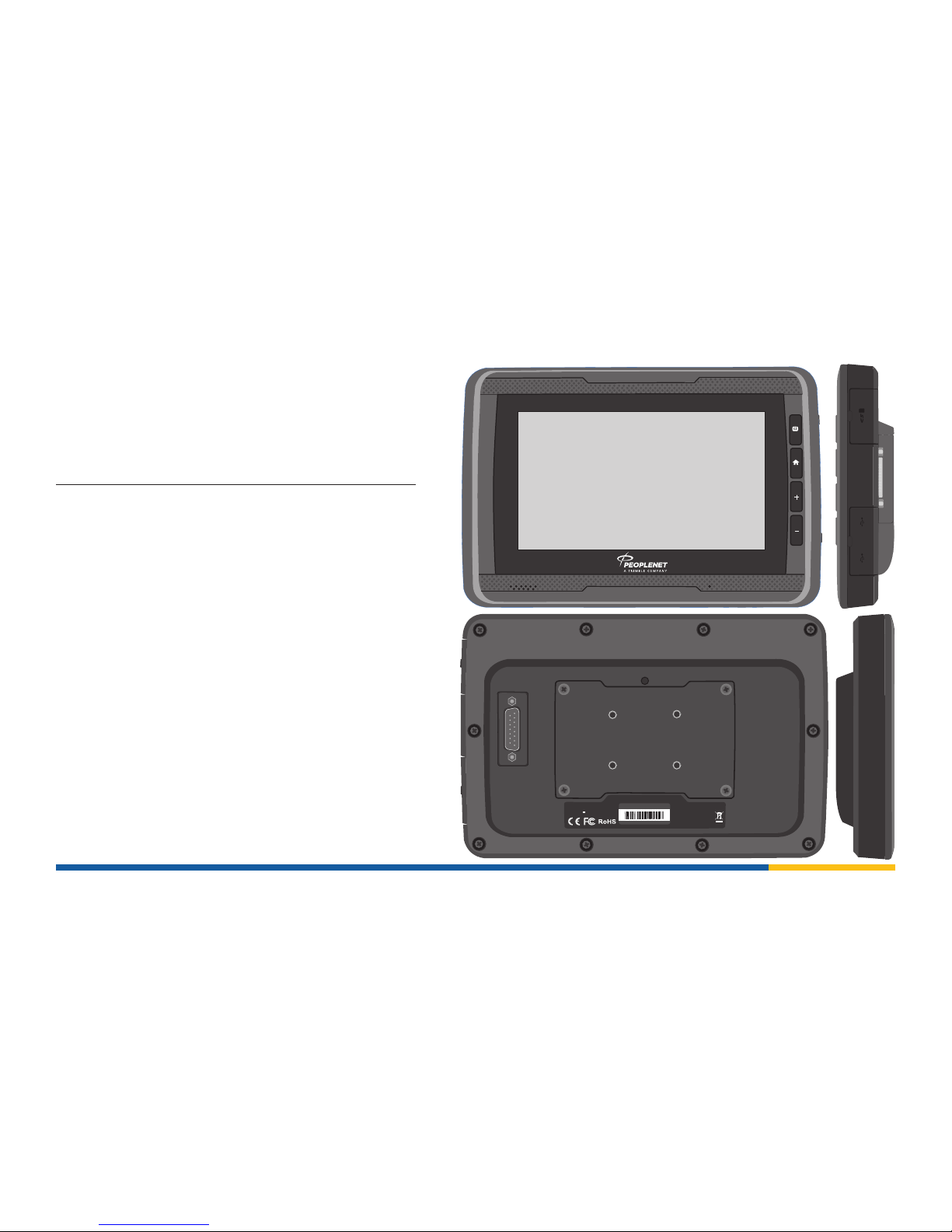
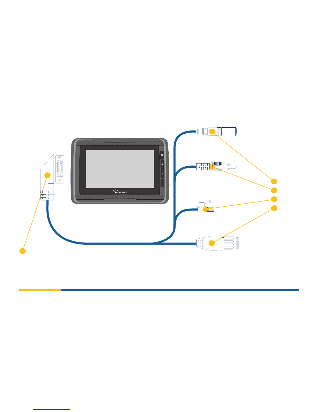
SYSTEM OVERVIEW
INTERFACE
AUDIO
POWER
DATA
VIDEO
Page 7

7
HARDWARE INSTALLATION
Trimble recommends using the RAM Mounting System
included in your PeopleNet Display.5 Kit.
Step 1. Verify there are no wires behind the backing surface
that may be damaged by drilling into the surface.
Step 2. Mark and Drill the holes for the mounting bracket
using a 3/16” drill bit.
Step 3. Attach the RAM Ball Joint Mount to the dash using
the supplied 8-32 7/16” screws.
RAM MOUNT BALL JOINT
Page 8
8
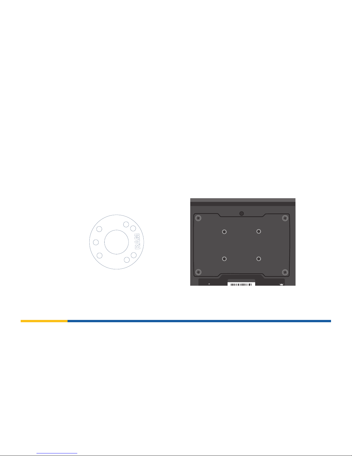
HARDWARE INSTALLATION
Step 4. Line up the RAM Ball Joint Mount to ensure that it will be attached with 4 screws to the PeopleNet Display.5. Using
the supplied 8-32 stainless steel screws and tooth lock washer, attach the mounting plate.
Serial No.: PD51000000001Model: PD5
P/N : L019-0156
Input : 12V1A
Trade Name : PEOPLENET
Manufacturer : PEOPLENET
6807 Shady Oak Road Eden Prairie,
input : 12V 1A
RAM MOUNT BALL JOINT
Page 9
9
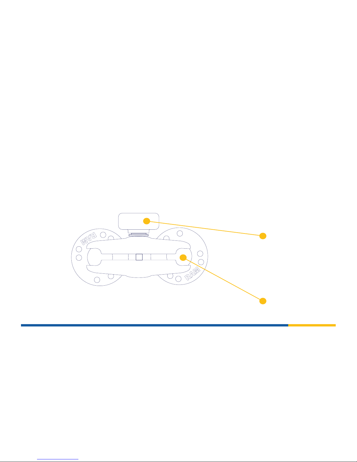
HARDWARE INSTALLATION
Step 5. Loosen the RAM mount arm. Slide the arm over the ends of the
mounted ball joints. Position the device to the desired position and
tighten the arm with the adjuster. To re-position, loosen the arm
prior to making any adjustments and then re-tighten to lock in
place.
BALL JOINT
ADJUSTER
Page 10

10
Serial No.: PD51000000001
Model: PD5
P/N : L019-0156
Input : 12V1A
Contains FCC ID : XPYEMMYW161
Trade Name : PEOPLENET
Importer : PEOPLENET
Manufacturer : PEOPLENET
MN 55344, USA
MN 55344, USA
6807 Shady Oak Road Eden Prairie,
6807 Shady Oak Road Eden Prairie,
Made in China
input : 12V 1A
CABLE CONNECTION
Step 6. Connect the interface cable to the back of the PeopleNet Display.5. Make sure the pins are positioned squarely and
the thumb screws are evenly tightened.
TIGHTEN
Page 11

11
DISPLAY CONNECTOR MALE
from PeopleNet Display.5
DISPLAY CONNECTOR FEMALE
from vehicle gateway
GROOVE
Line up corresponding grooves.
CABLE CONNECTION
Step 7. Route the cable into the dash. Make sure the cable is not in a position where it could be worn or pinched. If the audio
and/or video cables are not used secure them in the dash.
Step 8. Holding the display connector cable (male) from the PeopleNet Display.5 to the display connector cable (female)
from the vehicle gateway line up the groove inside the bottom of the connectors and push connectors together.
Once pushed together rotate the sheathing clockwise to nger tighten the connectors.
Page 12

12
CABLE CONNECTION
Step 9. Connect the 2-Pin Power connector (male) to the corresponding power and ground connector (female) from the
vehicle gateway. This connection will provide vehicle-direct power and ground for the display.
POWER CONNECTOR MALE
from PeopleNet Display.5
POWER CONNECTOR FEMALE
from vehicle gateway
Front View
Front View
Page 13

13
INDICATOR LIGHTS
Step 10. Turn the vehicle ignition to ON and verify the device boots up.
POWER BUTTON / CHARGING INDICATOR
Solid Blue - Powered on but not
charging.
Solid Green - Device is charging.
Blinking Green - Issue with battery
or imminent loss of battery power.
Page 14

14
INITIALIZATION PROCEDURE
Step 1. When the PeopleNet Mobile Software™ runs for the rst time, it will indicate that it needs an installation.
Enter 9238 for the admin password.
Tap OK.
Page 15

15
INITIALIZATION PROCEDURE
Step 2. You will be prompted to enter the device serial number (DSN) of the vehicle gateway. The device serial number is
located on a sticker placed on the vehicle gateway. Note the device serial number as it will be used in multiple set up
steps.
The device serial number starts with a 1 and is 8 digits long. Example: 11000682
Enter the device serial number of your vehicle gateway.
Tap OK.
Page 16

16
INITIALIZATION PROCEDURE
Step 3. The PeopleNet Display.5 will attempt to connect to the vehicle gateway’s Wi-Fi network based on the device serial
number you entered in Step 2.
If the connection fails, verify the vehicle gateway is powered on and that the correct device serial number was
entered.
Page 17

17
INITIALIZATION PROCEDURE
Step 4. The rst time your PeopleNet Display.5 connects to the vehicle gateway, the PeopleNet Display.5 will gather
necessary communication information from the vehicle gateway. The PeopleNet Display.5 will reboot once the
information is received from the vehicle gateway.
Tap OK or let the timer expire.
The PeopleNet Display.5 will reboot and utilize the new settings.
Page 18

18
INITIALIZATION PROCEDURE
Step 5. Re-enter the device serial number of your vehicle gateway.
Tap OK.
Page 19

19
INITIALIZATION PROCEDURE
Step 6. The PeopleNet Display.5 will attempt to connect to the Wi-Fi network of the vehicle gateway based on the device
serial number you entered in Step 5.
If the connection fails, verify the vehicle gateway is powered on and that the correct device serial number was
entered.
Page 20

20
INITIALIZATION PROCEDURE PEOPLENET CONNECTED GATEWAY INSTALLATION ONLY
You will need an Installer ID and Password. If you do not have an Installer ID/Password please reach out to your system administrator.
Step 7. Once the vehicle gateway’s Wi-Fi network is established, you will be prompted to enter your installation credentials.
Tap the box under Installer ID, then use the on-screen keyboard to enter the Installer ID.
Tap the box under Installer Password, then use the on-screen keyboard to enter the Installer Password.
Tap OK.
NOTE:
If you encounter an error message, verify that the
installation credentials were typed correctly.
If the installation credentials are correct, try rebooting
the PeopleNet Display.5 and the PeopleNet Connected
Gateway™. The most common issue is the PeopleNet
Display.5 or PeopleNet Connected Gateway™ are unable
to talk to the PeopleNet Fleet Manager, and rebooting will
cause the PeopleNet Connected Gateway to reinitialize its
modem and re-register with the cellular network.
Page 21

21
INITIALIZATION PROCEDURE
Step 8. Select the type of installation you are performing.
YES - The vehicle gateway has not been installed in a vehicle before. The vehicle gateway will display Pending in the
PeopleNet Fleet Manager.
NO- This is an existing installation where the vehicle gateway has been previously paired with a display.
Page 22

22
INITIALIZATION PROCEDURE
Step 9. If YES was selected.
Type your Installer ID.
This Installer ID will not be the same as the installation credentials, and only digits are allowed in this
eld. If you do not have an Installer ID, type a number that will dierentiate you from other installers
in your eet (the Installer ID used at this screen is recorded in the PeopleNet Fleet Manager; it has
no impact on your ability to complete an install).
Type the Vehicle ID that will be used as a unique identier in the PeopleNet Fleet Manager.
Tap Submit.
Page 23

23
INITIALIZATION PROCEDURE
Step 9. If NO was selected.
Type your Installer ID.
This Installer ID will not be the same as the installation credentials, and only digits are allowed in this
eld. If you do not have an Installer ID, type a number that will dierentiate you from other installers
in your eet (the Installer ID used at this screen is recorded in the PeopleNet Fleet Manager; it has
no impact on your ability to complete an install).
Type the Vehicle ID that will be used as a unique identier in the PeopleNet Fleet Manager.
If you are changing the vehicle gateway in this vehicle, type the old device serial number (DSN).
Tap Submit.
Page 24

24
INITIALIZATION PROCEDURE
Step 10. After tapping Submit, the message “Submitting Installation request. This process could take several
minutes” will appear under the Installer ID eld.
The Submit button will be grayed out.
Page 25

25
INITIALIZATION PROCEDURE
Step 11. When the PeopleNet Display.5 has completed the data call to the PeopleNet Fleet Manager, the PeopleNet
Display.5 will show “Installing Data Store, Activation nearly complete”.
ERROR CODE POSSIBILITIES
Yes, this is a new installation was selected - verify that
the vehicle ID you’re trying to use is not already in use, and
you should have selected “no, this is not a new installation”.
No, this is not a new installation - verify that the vehicle
number used does already exist, and the correct device
serial number was entered into the Old DSN eld.
Page 26

26
INITIALIZATION PROCEDURE
Step 12. Activating Device will be displayed when the information has been entered correctly and settings are being
downloaded from the PeopleNet Fleet Manager.
When all the settings have been downloaded from the PeopleNet Fleet Manager, the words Activating will change
to Activated on the device.
PeopleNet Mobile software will then reboot and the Driver Login screen wil load.
The Initialization Procedure is complete.
Page 27

27
Go to System > OBC Diagnostic > Diagnostic Basic.
Verify the following information:
GPS = 3D
Cell Strength is >2
Go to System > OBC Diagnostic > Diagnostic Device.
Verify the following information:
Ignition displays ON when the vehicle key is on and
displays OFF when the key is o and OFF in accessory.
With the vehicle ignition key ON, go to System > OBC
Diagnostic > Diagnostic PerformX.
Verify the following information:
RPM matches engine tachometer on the dash panel.
Odometer Type: ECM and Odo: matches dash.
FUEL TYPE = ECM and FUEL: >0 gallons.
Conrm the Display Power button LED is green, indicating
charging.
Disconnect the PeopleNet Display.5 from the cable and
verify the LED turns to Blue and the display remains
powered on.
NOTE: A fully charged battery will supply power for
roughly 15 minutes, though a new unit may not have a
full charge.
Any accessories (Satellite, OBDii, GPIO, PTO) activated and
conrmed. See accessory guide for details.
TEST INITIALIZATION
Once the PeopleNet Display.5 and the vehicle gateway are paired, a full test is recommended. Follow the steps below to
conrm functionality. You will need a Driver ID and Password. Contact your system administrator if you need a test ID.
Login to the device.
Page 28

28
TROUBLESHOOTING
HARD RESET BUTTON
A hard reboot button is available under the top access panel on the PeopleNet Displays.5’s right side. Open the top access
panel. Hold in the button to reboot the device if needed.
RESET BUTTON
Page 29

29
TROUBLESHOOTING
CABLE PIN OUT
This cable pin-out can aid in troubleshooting if the display fails to boot
14
1234567
8
91011121315
PeopleNet Display.5 Cable L-016-0642 Mating Connector View
PIN DESCRIPTION
8 Vehicle 11-24 volt constant power
7 Vehicle ground
6 Vehicle gateway 12 volt ignition power
3 Vehicle gateway ground
Page 30

TRANSFORMING THE WAY THE WORLD WORKS
UNITED STATES
Trimble Transportation
4400 Baker Road
Minnetonka MN 55343
CANADA
Trimble Transportation
1100 Burloak Drive
Suite 300 Burlington
Ontario Canada L71 682
CONTACT
+1-888-346-3486 Phone
+1-952-908-6129 Fax
info@peoplenetonline.com
www.peoplenetonline.com
© 2018 Trimble Inc. All rights reserved. Trimble, the Globe & Triangle logo, PeopleNet Display.5,
PeopleNet Mobile Software, PeopleNet Connected Gateway, and PeopleNet Fleet Manager are
trademarks of Trimble Inc. All other trademarks are the property of their respective owners.
(08/18)
 Loading...