

Page 1

NetRS™ GPS Receiver
User Guide
F
Version 1.11
Revision A
November 2004
Page 2

Corporate Office
Trimble Navigation Limited
Geomatics and Engineering Division
5475 Kellenburger Road
Dayton, Ohio 45424-1099
USA
800-538-7800 (toll free in USA)
+1-937-245-5600 Phone
+1-937-233-9004 Fax
www.trimble.com
Copyright and Trademarks
© 2003–2004, Trimble Navigation Limited. All rights
reserved.
Trimble, and the Globe & Triangle logo are trademarks
of Trimble Navigation Limited, registered in the United
States Patent and Trademark Office and in other
countries. CMR+, EVEREST, NetRS, TRIMCOMM,
TRIMMARK, TRIMTALK, and Zephyr are trademarks
of Trimble Navigation Limited. Microsoft and Windows
are either registered trademarks or trademarks of
Microsoft Corporation in the United States and/or other
countries. All other trademarks are the property of their
respective owners.
This product is covered by the following patents:
US: 5148179, 5187450, 5202694, 5311149, 5402450,
5493588, 5515057, 5519620, 5602741, 5757646,
6252863, 6175848. US and Foreign patents pending.
Release Notice
This is the November 2004 release (Revision A) of the
NetRS GPS Receiver User Guide. It applies to version 1.11
of the NetRS GPS receiver.
The following limited warranties give you specific legal
rights. You may have others, which vary from
state/jurisdiction to state/jurisdiction.
Product Limited Warranty
Subject to the terms and conditions set forth herein,
Trimble warrants that for a period of (1) year starting
from the date of purchase, this Trimble product,
including any software components, (the "Product") will
substantially conform to Trimble's publicly available
specifications for the Product and that the hardware and
any storage media components of the Product will be
substantially free from defects in materials and
workmanship.
Product Software
Product software, whether built into hardware circuitry
as firmware, provided as a standalone computer software
product, embedded in flash memory, or stored on
magnetic or other media, is licensed and not sold. If
accompanied by a separate end user license agreement,
use of any such software will be subject to the terms of
such end user license agreement (including any differing
limited warranty terms, exclusions and limitations),
which shall control over the terms and conditions set
forth in this limited warranty).
Software Updates
Please refer to the "Firmware" heading of the NetRS
GPS Receiver web site user interface for information
about software updates available for this Product.
Warranty Exclusions and Disclaimer
This Product limited warranty shall only apply in the
event and to the extent that (i) the Product is properly
and correctly installed, configured, interfaced,
maintained, stored, and operated in accordance with
Trimble's relevant operator's manual and specifications,
and; (ii) the Product is not modified or misused. This
Product limited warranty shall not apply to, and Trimble
shall not be responsible for defects or performance
problems resulting from (i) the combination or
utilization of the Product with hardware or software
products, information, data, systems, interfaces or
devices not made, supplied or specified by Trimble; (ii)
the operation of the Product under any specification
other than, or in addition to, Trimble's standard
specifications for its products; (iii) the unauthorized,
installation, modification, or use of the Product; (iv)
damage caused by: accident, lightning or other electrical
discharge, fresh or salt water immersion or spray; or
exposure to environmental conditions for which the
Product is not intended; or (v) normal wear and tear on
consumable parts (e.g., batteries). Trimble does not
warrant or guarantee the results obtained through the use
of the Product. TRIMBLE IS NOT RESPONSIBLE
FOR THE OPERATION OR FAILURE OF
OPERATION OF GPS SATELLITES OR THE
AVAILABILITY OF GPS SATELLITE SIGNALS.
THE FOREGOING LIMITED WARRANTY TERMS
STATE TRIMBLE'S ENTIRE LIABILITY, AND
YOUR EXCLUSIVE REMEDIES, RELATING TO
PERFORMANCE OF THE TRIMBLE PRODUCT.
EXCEPT AS OTHERWISE EXPRESSLY PROVIDED
HEREIN, THE PRODUCT AND ACCOMPANYING
DOCUMENTATION AND MATERIALS ARE
PROVIDED "AS-IS" AND WITHOUT EXPRESS OR
IMPLIED WARRANTY OF ANY KIND, BY EITHER
TRIMBLE OR ANYONE WHO HAS BEEN
INVOLVED IN ITS CREATION, PRODUCTION,
INSTALLATION, OR DISTRIBUTION, INCLUDING,
BUT NOT LIMITED TO, THE IMPLIED
WARRANTIES OF MERCHANTABILITY AND
FITNESS FOR A PARTICULAR PURPOSE, TITLE,
AND NONINFRINGEMENT. THE STATED
EXPRESS WARRANTIES ARE IN LIEU OF ALL
OBLIGATIONS OR LIABILITIES ON THE PART OF
TRIMBLE ARISING OUT OF, OR IN CONNECTION
WITH, ANY PRODUCT.
NetRS GPS Receiver User Guide
Page 3

SOME STATES AND JURISDICTIONS DO NOT
ALLOW LIMITATIONS ON DURATION OR THE
EXCLUSION OF AN IMPLIED WARRANTY, SO
THE ABOVE LIMITATION MAY NOT APPLY TO
YOU.
Limitation of Liability
TRIMBLE'S ENTIRE LIABILITY UNDER ANY
PROVISION HEREIN SHALL BE LIMITED TO THE
AMOUNT PAID BY YOU FOR THE PRODUCT. TO
THE MAXIMUM EXTENT PERMITTED BY
APPLICABLE LAW, IN NO EVENT SHALL
TRIMBLE OR ITS SUPPLIERS BE LIABLE FOR
ANY INDIRECT, SPECIAL, INCIDENTAL OR
CONSEQUENTIAL DAMAGES WHATSOEVER
UNDER ANY CIRCUMSTANCE OR LEGAL
THEORY RELATING IN ANYWAY TO THE
PRODUCTS, SOFTWARE AND ACCOMPANYING
DOCUMENTATION AND MATERIALS,
(INCLUDING, WITHOUT LIMITATION, DAMAGES
FOR LOSS OF BUSINESS PROFITS, BUSINESS
INTERRUPTION, LOSS OF DATA, OR ANY OTHER
PECUNIARY LOSS), REGARDLESS OF WHETHER
TRIMBLE HAS BEEN ADVISED OF THE
POSSIBILITY OF ANY SUCH LOSS AND
REGARDLESS OF THE COURSE OF DEALING
WHICH DEVELOPS OR HAS DEVELOPED
BETWEEN YOU AND TRIMBLE. BECAUSE SOME
STATES AND JURISDICTIONS DO NOT ALLOW
THE EXCLUSION OR LIMITATION OF LIABILITY
FOR CONSEQUENTIAL OR INCIDENTAL
DAMAGES, THE ABOVE LIMITATION MAY NOT
APPLY TO YOU.
Export/Import Restrictions. By your acquisition or use
of this Product you agree to comply with all applicable
export and import laws and restrictions and regulations
of the United States and foreign countries, and shall not
export, re-export, import, transfer, or divert the Product
in whole or in part (i) to any destination restricted or
prohibited by U.S. export control laws or to any national
or resident thereof, (ii) to any denied or restricted
individual or entity under such laws and regulations, or
(iii) without all necessary authorizations required by law.
NOTE: THE ABOVE TRIMBLE LIMITED
WARRANTY PROVISIONS WILL NOT APPLY
TO PRODUCTS PURCHASED IN THOSE
JURISDICTIONS, SUCH AS COUNTRIES OF
THE EUROPEAN ECONOMIC COMMUNITY, IN
WHICH PRODUCT WARRANTIES ARE
OBTAINED FROM THE LOCAL DISTRIBUTOR.
IN SUCH CASE, PLEASE CONTACT YOUR
TRIMBLE DEALER FOR APPLICABLE
WARRANTY INFORMATION.
Notices
Class B Statement – Notice to Users. This equipment
has been tested and found to comply with the limits for a
Class B digital device, pursuant to Part 15 of the FCC
rules. These limits are designed to provide reasonable
protection against harmful interference in a residential
installation. This equipment generates, uses, and can
radiate radio frequency energy and, if not installed and
used in accordance with the instructions, may cause
harmful interference to radio communication. However,
there is no guarantee that interference will not occur in a
particular installation. If this equipment does cause
harmful interference to radio or television reception,
which can be determined by turning the equipment off
and on, the user is encouraged to try to correct the
interference by one or more of the following measures:
– Reorient or relocate the receiving antenna.
– Increase the separation between the equipment and
the receiver.
– Connect the equipment into an outlet on a circuit
different from that to which the receiver is connected.
– Consult the dealer or an experienced radio/TV
technician for help.
Changes and modifications not expressly approved by
the manufacturer or registrant of this equipment can void
your authority to operate this equipment under Federal
Communications Commission rules.
Regulations and Safety
S
TATEMENT ACCORDING FCC PART 15.19
This device complies with Part 15 of the FCC Rules.
Operation is subject to the following two conditions: (1)
this device may not cause harmful interference, and (2)
this device must accept any interference received,
including interference that may cause undesired
operation.
TATEMENT ACCORDING FCC PART 15.21
S
Modifications not expressly approved by Trimble could
void the user's authority to operate the equipment.
CE Declaration of Conformity
This product conforms to the following standards, and
therefore complies with the requirements of the R&TTE
Directive 1999/5/EC, which specifies compliance with
the essential requirements of EMC Directive
89/336/EEC and Low Voltage Directive 73/23/EEC:
EMC Emissions:BSEN 55022:1998 (W/A1:00) Class B
EMC Immunity:EN 55024:1998
Safety:EN 60950:2000
Mark First Applied: 03
The technical file is maintained at: Trimble Navigation
Limited, 645 North Mary Avenue, Post Office Box
3642, Sunnyvale, CA 94088-3642, USA
NetRS GPS Receiver User Guide
Page 4

NetRS GPS Receiver User Guide
Page 5

Contents
1 Introduction . . . . . . . . . . . . . . . . . . . . . . . . . . 1
About the NetRS . . . . . . . . . . . . . . . . . . . . . . . . . . . . . . . 1
Related Information . . . . . . . . . . . . . . . . . . . . . . . . . . . . . . 2
Technical Assistance . . . . . . . . . . . . . . . . . . . . . . . . . . . . . 2
Your Comments . . . . . . . . . . . . . . . . . . . . . . . . . . . . . . . . 2
2 Overview . . . . . . . . . . . . . . . . . . . . . . . . . . . . 3
The Network Appliance Concept . . . . . . . . . . . . . . . . . . . . . . . 5
NetRS Services . . . . . . . . . . . . . . . . . . . . . . . . . . . . . . . . 6
Use and Care . . . . . . . . . . . . . . . . . . . . . . . . . . . . . . . . . 9
Electronic Interference . . . . . . . . . . . . . . . . . . . . . . . . . . . . 9
Security Threat (COCOM) Limits . . . . . . . . . . . . . . . . . . . . . . 9
3 Features and Functions . . . . . . . . . . . . . . . . . . . 11
Features of the Receiver. . . . . . . . . . . . . . . . . . . . . . . . . . . 12
Front panel . . . . . . . . . . . . . . . . . . . . . . . . . . . . . . 13
Rear panel . . . . . . . . . . . . . . . . . . . . . . . . . . . . . . 14
Power ports. . . . . . . . . . . . . . . . . . . . . . . . . . . . . . 17
Button Functions . . . . . . . . . . . . . . . . . . . . . . . . . . . . . . 18
Power button operations . . . . . . . . . . . . . . . . . . . . . . . 18
Power saving mode. . . . . . . . . . . . . . . . . . . . . . . . . . 19
Other power operations . . . . . . . . . . . . . . . . . . . . . . . 20
To erase the almanac and the ephemeris . . . . . . . . . . . . . . . 21
To reset the receiver to factory defaults settings . . . . . . . . . . . 21
LED Functions . . . . . . . . . . . . . . . . . . . . . . . . . . . . . . . 22
LED startup sequence . . . . . . . . . . . . . . . . . . . . . . . . 22
NetRS GPS Receiver User Guide v
Page 6

Contents
LED flash patterns . . . . . . . . . . . . . . . . . . . . . . . . . . 25
4 Setting Up the Receiver . . . . . . . . . . . . . . . . . . . 27
Setup Guidelines . . . . . . . . . . . . . . . . . . . . . . . . . . . . . . 28
Environmental conditions . . . . . . . . . . . . . . . . . . . . . . 28
Sources of electrical interference . . . . . . . . . . . . . . . . . . 28
Uninterruptible power supply . . . . . . . . . . . . . . . . . . . . 29
Lightning protection . . . . . . . . . . . . . . . . . . . . . . . . . 29
Mounting the receiver . . . . . . . . . . . . . . . . . . . . . . . . 30
Placing the antenna. . . . . . . . . . . . . . . . . . . . . . . . . . 30
Connecting the Receiver to Other Devices . . . . . . . . . . . . . . . . . 31
Antenna. . . . . . . . . . . . . . . . . . . . . . . . . . . . . . . . 31
Antenna cabling . . . . . . . . . . . . . . . . . . . . . . . . . . . 31
Met-Tilt sensors . . . . . . . . . . . . . . . . . . . . . . . . . . . 32
Dial-up modems and terminal adapters . . . . . . . . . . . . . . . 33
Radio modems . . . . . . . . . . . . . . . . . . . . . . . . . . . . 34
External frequency reference. . . . . . . . . . . . . . . . . . . . . 34
5 Configuring the Receiver . . . . . . . . . . . . . . . . . . 35
Setting up Communications. . . . . . . . . . . . . . . . . . . . . . . . . 36
Configuring the Ethernet connection. . . . . . . . . . . . . . . . . 37
Configuring the Receiver Through a Web Browser. . . . . . . . . . . . . 41
Web-based menu . . . . . . . . . . . . . . . . . . . . . . . . . . . 41
Configuring the Receiver for Connected Devices . . . . . . . . . . . . . 45
Dial-up modem, radio modem, or terminal adapter . . . . . . . . . 45
Configuring Met-Tilt sensors . . . . . . . . . . . . . . . . . . . . 47
Configuring the GPSBase or GPSNet software . . . . . . . . . . . 48
Updating the Receiver Firmware . . . . . . . . . . . . . . . . . . . . . . 49
Downloading the firmware upgrade . . . . . . . . . . . . . . . . . 50
Uploading the firmware . . . . . . . . . . . . . . . . . . . . . . . 50
Installing the firmware upgrade . . . . . . . . . . . . . . . . . . . 50
vi NetRS GPS Receiver User Guide
Page 7

Contents
6 Logging and Managing Data . . . . . . . . . . . . . . . . 53
Data Logging Sessions . . . . . . . . . . . . . . . . . . . . . . . . . . . 54
Creating or editing a session . . . . . . . . . . . . . . . . . . . . . 56
Enabling a session . . . . . . . . . . . . . . . . . . . . . . . . . . 56
Disabling a session . . . . . . . . . . . . . . . . . . . . . . . . . . 56
Data Format . . . . . . . . . . . . . . . . . . . . . . . . . . . . . . . . . 56
Naming Files . . . . . . . . . . . . . . . . . . . . . . . . . . . . . . . . 56
Auto Delete. . . . . . . . . . . . . . . . . . . . . . . . . . . . . . 57
Managing Files Through the Web Interface . . . . . . . . . . . . . . . . 58
Storing files . . . . . . . . . . . . . . . . . . . . . . . . . . . . . 58
Sorting files . . . . . . . . . . . . . . . . . . . . . . . . . . . . . 59
Downloading files . . . . . . . . . . . . . . . . . . . . . . . . . . 59
Deleting files . . . . . . . . . . . . . . . . . . . . . . . . . . . . . 59
Managing Files Using FTP . . . . . . . . . . . . . . . . . . . . . . . . . 60
7 Real-Time Data and Services . . . . . . . . . . . . . . . . 63
Streamed Data Services . . . . . . . . . . . . . . . . . . . . . . . . . . . 64
RT17 . . . . . . . . . . . . . . . . . . . . . . . . . . . . . . . . . 64
Trimcom . . . . . . . . . . . . . . . . . . . . . . . . . . . . . . . 64
BINEX . . . . . . . . . . . . . . . . . . . . . . . . . . . . . . . . 65
CMR . . . . . . . . . . . . . . . . . . . . . . . . . . . . . . . . . 65
RTCM . . . . . . . . . . . . . . . . . . . . . . . . . . . . . . . . 65
Collecting Data as a Client . . . . . . . . . . . . . . . . . . . . . . . . . 66
8 Other System Information. . . . . . . . . . . . . . . . . . 67
Default Settings . . . . . . . . . . . . . . . . . . . . . . . . . . . . . . . 68
Specifications . . . . . . . . . . . . . . . . . . . . . . . . . . . . . . . . 70
Cables and Connectors . . . . . . . . . . . . . . . . . . . . . . . . . . . 73
Ports . . . . . . . . . . . . . . . . . . . . . . . . . . . . . . . . . 73
Cables and connectors . . . . . . . . . . . . . . . . . . . . . . . . 74
Port pinouts. . . . . . . . . . . . . . . . . . . . . . . . . . . . . . 74
1PPS Output. . . . . . . . . . . . . . . . . . . . . . . . . . . . . . . . . 76
1PPS Pulse Definition . . . . . . . . . . . . . . . . . . . . . . . . 76
NetRS GPS Receiver User Guide vii
Page 8

Contents
Deployment Issues . . . . . . . . . . . . . . . . . . . . . . . . . . . . . 77
Planning . . . . . . . . . . . . . . . . . . . . . . . . . . . . . . . 77
Configuring from Factory Defaults . . . . . . . . . . . . . . . . . 78
Monitoring Operation . . . . . . . . . . . . . . . . . . . . . . . . 78
Changing Modes . . . . . . . . . . . . . . . . . . . . . . . . . . . 79
Changing the Configuration . . . . . . . . . . . . . . . . . . . . . 79
NetRS Support Software . . . . . . . . . . . . . . . . . . . . . . . . . . 80
Data Conversion . . . . . . . . . . . . . . . . . . . . . . . . . . . 80
T00 to DAT file conversion . . . . . . . . . . . . . . . . . . . 80
RT17 to DAT file conversion. . . . . . . . . . . . . . . . . . . 81
DAT to RINEX file conversion . . . . . . . . . . . . . . . . . 81
Setting Up a PPP Connection . . . . . . . . . . . . . . . . . . . . . . . . 83
Linux Operating System . . . . . . . . . . . . . . . . . . . . . . . 83
Windows Operating System . . . . . . . . . . . . . . . . . . . . . 84
Creating a PPP connection . . . . . . . . . . . . . . . . . . . . 85
Configuring a PPP connection . . . . . . . . . . . . . . . . . . 86
Using the PPP connection . . . . . . . . . . . . . . . . . . . . 89
Closing the PPP session . . . . . . . . . . . . . . . . . . . . . 89
Re-connecting the PPP session . . . . . . . . . . . . . . . . . . 90
Editing PPP connection properties . . . . . . . . . . . . . . . . 90
Deleting a PPP connection . . . . . . . . . . . . . . . . . . . . 90
Glossary . . . . . . . . . . . . . . . . . . . . . . . . . . . 93
Index . . . . . . . . . . . . . . . . . . . . . . . . . . . . 101
viii NetRS GPS Receiver User Guide
Page 9

CHAPTER
1
Introduction 1
Welcome to the NetRS GPS Receiver User Guide. This manual
describes how to set up and use the Trimble® NetRS™ GPS receiver.
Even if you have used other Global Positioning System (GPS)
products before, Trimble recommends that you spend some time
reading this manual to learn about the special features of this product.
If you are not familiar with GPS, visit the Trimble website
(www.trimble.com) for an interactive look at Trimble and GPS.
this publication assumes that you are familiar with the Microsoft®
Windows® operating system and know how to use a mouse, select
options from menus and dialogs, make selections from a list, and refer
to online help.
1.1 About the NetRS
The NetRS receiver is a dual-frequency GPS receiver that runs on a
Linux operating system and communicates mainly through local and
wide area networks. You can operate the receiver as a stand-alone
reference station or integrate it into a scalable network.
You will use an office computer to configure the receiver, access files,
or publish data files to a company intranet or to the Internet.
The NetRS receiver makes it easy for you to set up a powerful,
flexible, and reliable reference station for continuous operation.
NetRS Receiver User Guide 1
Page 10

1 Introduction
1.2 Related Information
Sources of related information include the following:
• Release notes – the release notes describe new features of the
product, information not included in the manuals, and any
changes to the manuals.
• Trimble training courses – consider a training course to help
you use your GPS system to its fullest potential. For more
information, visit the Trimble website at
www.trimble.com/support.html.
1.3 Technical Assistance
If you have a problem and cannot find the information you need in the
product documentation, contact your local dealer.
If you need to contact Trimble technical support:
1. Go to the Trimble website (www.trimble.com).
2. Click the
A–Z list of products appears.
3. Scroll to the bottom of the list.
4. Click the
5. Complete the form and then click
Alternatively, you can send an e-mail to
trimble_support@trimble.com
1.1 Your Comme n t s
Your feedback about the supporting documentation helps us to
improve it with each revision. E-mail your comments to
ReaderFeedback@trimble.com.
2 NetRS Receiver User Guide
Support button at the top of the screen. The Support
submit an inquiry link. A form appears.
Send.
Page 11

CHAPTER
2
Overview 2
In this chapter:
Q The Network Appliance Concept
Q NetRS Services
Q Use and Care
Q Electronic Interference
Q Security Threat (COCOM) Limits
NetRS GPS Receiver User Guide 3
Page 12

2 Overview
This chapter introduces the NetRS GPS receiver. This receiver makes
it easy to deploy a powerful, flexible, and reliable Continuously
Operating Reference Station (CORS).
The NetRS receiver integrates the latest dual-requency GPS
technology into a Linux processing and communications framework
that can operate as a stand-alone reference station or can be integrated
into a scalable network.
Because Internet Protocol (IP) is the primary communications method,
you can use public domain tools, such as a web browser and FTP
client, to configure the receiver and access logged data files.
Note – In this manual, all references to the “Internet” mean either a
wide area network (WAN) or a local area network (LAN) connection.
The Linux framework provides a foundation that allows Trimble to
extend and customize the system in ways which are not possible with a
proprietary operating system. Native support for standardized
interfaces means that you can use a variety of powerful commercial
and public domain software to work with the NetRS receiver.
You can enforce multiple levels of security, from a completely open
system that allows anonymous access to all features, to a secured
system that requires a password protected login for configuration
changes and/or file access.
Use the network management features to:
• Store the configuration of one receiver to a file and restore it to
the same receiver at a future date, or clone it to any other
receiver in a network.
4 NetRS GPS Receiver User Guide
Page 13

• Create a base configuration with a variety of operating modes.
You can then enable those modes as necessary, rather than
having to change the global state of the receiver from one mode
to another. For example, you can configure a number of
streaming services with different measurement intervals or
smoothing controls on different TCP or UDP ports. To activate
one or more modes, open the connection to the specific port.
This allows multiple clients to access any given streaming
service.
• Create multiple continuous logging session configurations and
then enable them only when required.
These features, and many more, shift the model of a GPS receiver
toward the concept of a “network appliance”.
2.1 The Network Appliance Concept
Traditionally, a GPS receiver has one user (operator). That person can
change settings without affecting other users.
Overview 2
With the NetRS receiver, an operator can configure the receiver once,
then make the receiver available, as a network appliance, for use by
one or more other users (clients).
An operator can set up the receiver to provide one or more services
that are accessible to one or more clients through the Internet. Once
the receiver is deployed, the client need make only minimal changes,
if any, to the receiver configuration.
When the receiver operates as a network appliance, it provides
services to all clients who are attached to the receiver through the
network.
Different streamed services can be configured on different ports. For
example, the service configuration on one port can have different data
rates or smoothing configurations from the service configuration on
another port. To obtain a service, the client has only to connect to a
specific port. In this way, most clients do not need to control the
NetRS GPS Receiver User Guide 5
Page 14

2 Overview
receiver. Any changes the operator makes to global settings, such as
masks, affects all clients of all services. However, the comprehensive
set of controls that has been provided for streamed service and data
logging configuration avoids global changes for the majority of
applications.
The NetRS receiver provides the following standard configuration and
data logging services:
Use ... to perform ...
FTP remote manual and/or automated operations to manage the
HTTP
HTTPS the same functions as the HTTP link, except that all data that is
2.2 NetRS Services
logged data file space
all manual and automated configuration operations
manual operations to manage the logged data file space
sent between the office computer and the receiver is
encrypted, which makes the link more secure.
The receiver can provide one or more streaming or query services over
an RS-232 serial port or a TCP/IP port:
• Protocol service
A protocol service provides functionality over a two-way link.
PPP enables IP communications over an RS-232 serial link;
Trimcom is a binary protocol used by Trimble PC software
applications; Met-Tilt provides sensor query and data logging.
• Streaming service
Any client with authorized access can obtain streamed
information, such as GPS measurements or RTCM corrections,
without having to control or issue commands to the receiver.
The client simply connects to the port that is streaming the
required information.
6 NetRS GPS Receiver User Guide
Page 15

Overview 2
• Query service
No command is required; opening the TCP port triggers data
transmission. A query service provides a single source for a
specific information type, and returns it without affecting other
continuous streams.
Multiple clients can connect simultaneously to a single
streaming or query port.
The NetRS receiver supports the following services:
Service Description Type
PPP
(Point to Point
Protocol)
Trimcom This service supports a subset of the standard Trimble
RT17 This service can be configured to provide various
BINEX The BINEX service provides streamed GPS observables,
This service is the Internet standard for transmitting IP
packets over serial lines. When you enable the serial port
for PPP, you can run the NetRS web configuration interface
over the serial port.
“Tr i m co m ” binary communications protocol. Trimcom is
used by Trimble software applications for configurable GPS
data streaming and queries.
combinations of real time GPS measurements, including
phase, pseudorange, carrier-to-noise ratios, and other
general information about each satellite that is tracked.
“RT17” is also the real-time streamed GPS measurement
information. It includes the same information that is stored
in Type 17 records in T00 and DAT files This is the basic
information used to produce GPS positions and
corrections.
satellite orbits, and various optional data about the site and
receiver. For more information about the BINEX format, go
to http://binex.unavco.org/.
Protocol
Protocol
Streaming
Streaming
NetRS GPS Receiver User Guide 7
Page 16

2 Overview
Service Description Type
Met-Tilt This service can be configured to send one or more device
initialization and query strings on a regular basis to obtain
measurements from external sensors. These sensors
include those used to collect meteorological data and/or
deformation data (where the tilt of the sensor is measured).
Data from the Met or the Tilt sensor is included in any
active RT17 or BINEX stream.
Depending on whether you are logging or streaming data,
all data is included in T00, BINEX, or RT17 format.
RTCM This RTCM (Radio Technical Commission for Maritime
Services) service can be configured to send one or more
RTCM SC-104 messages from the specified port.
CMR/ CMR+ This service can be configured to provide real-time GPS
measurements in Compact Measurement Record format,
primarily for RTK applications that use CMR or CMR+.
Ephemerides This service provides a complete set of GPS ephemerides
(orbits) each time an application connects to the selected
port.
Almanacs This service provides a complete GPS almanac each time
an application connects to the selected port.
SV Status This service provides a variety of information about the
current GPS and WAAS/EGNOS constellation.
Protocol
Streaming
Streaming
Query
Query
Query
8 NetRS GPS Receiver User Guide
Page 17

2.3 Use and Care
The NetRS receiver is designed to withstand the treatment and
environment that typically occurs in a CORS installation. However,
the receiver is a high-precision electronic instrument and should be
treated with reasonable care.
Overview 2
C
2.4 Electronic Interference
Caution – Operating or storing the NetRS receiver outside the specified
temperature range can damage it. For details, see Specifications,
page 70.
High-power signals from a nearby radio or radar transmitter can
overwhelm the receiver circuits. This does not harm the instrument,
but it can prevent the receiver electronics from functioning correctly.
Do not locate the receiver or antenna within 400 meters of powerful
radar, television, or other transmitters, or GPS antennas. Low-power
transmitters, such as those in cell phones and two-way radios,
normally do not interfere with NetRS receiver operations.
2.5 Security Threat (COCOM) Limits
The U.S. Department of Commerce requires that all exportable GPS
products contain performance limitations so that they cannot be used
in a manner that could threaten the security of the United States. The
following limitations are implemented on the NetRS receiver:
Immediate access to satellite measurements and navigation results is
disabled when the receiver velocity is computed to be greater than
1000 knots, or its altitude is computed to be above 18,000 meters
(approximately 59,000 ft). The receiver GPS subsystem will reset until
the security threat (COCOM) situation clears. As a result, all logging
and stream configurations will stop until the GPS subsystem is
cleared.
NetRS GPS Receiver User Guide 9
Page 18

2 Overview
10 NetRS GPS Receiver User Guide
Page 19

CHAPTER
3
Features and Functions 3
In this chapter:
Q Features of the Receiver
Q Button Functions
Q LED Functions
NetRS GPS Receiver User Guide 11
Page 20
3 Features and Functions
This chapter describes the physical features of the NetRS receiver. It
also describes how to perform some basic receiver functions.
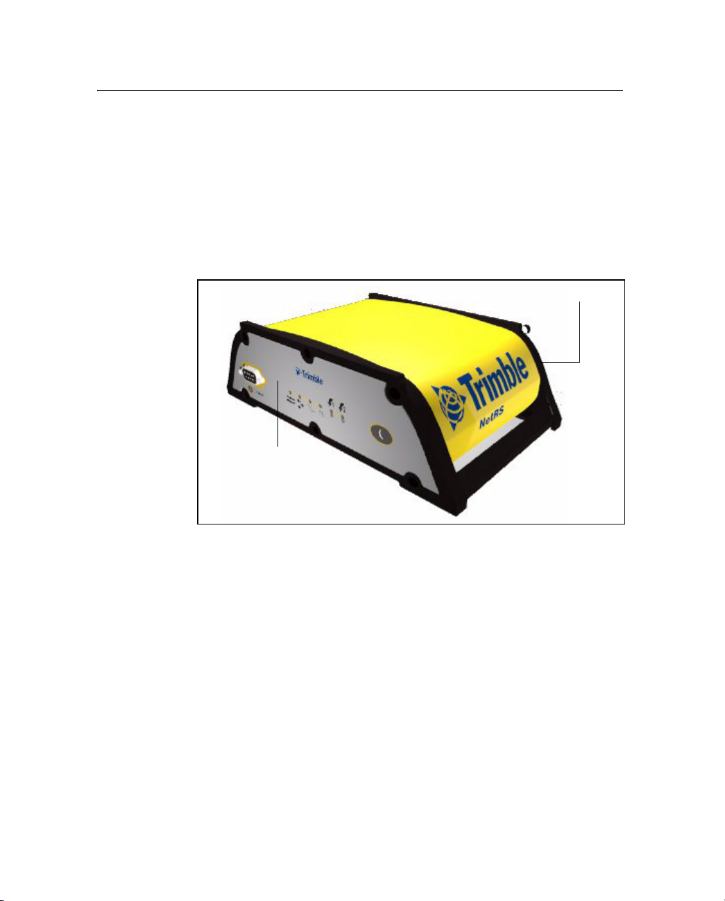
3.1 Features of the Receiver
All operating controls, ports, and connectors on the receiver are on the
front or the rear panels, see Figure 3.1.
Front panel
Rear panel
Figure 3.1 Receiver front and rear panels
12 NetRS GPS Receiver User Guide
Page 21
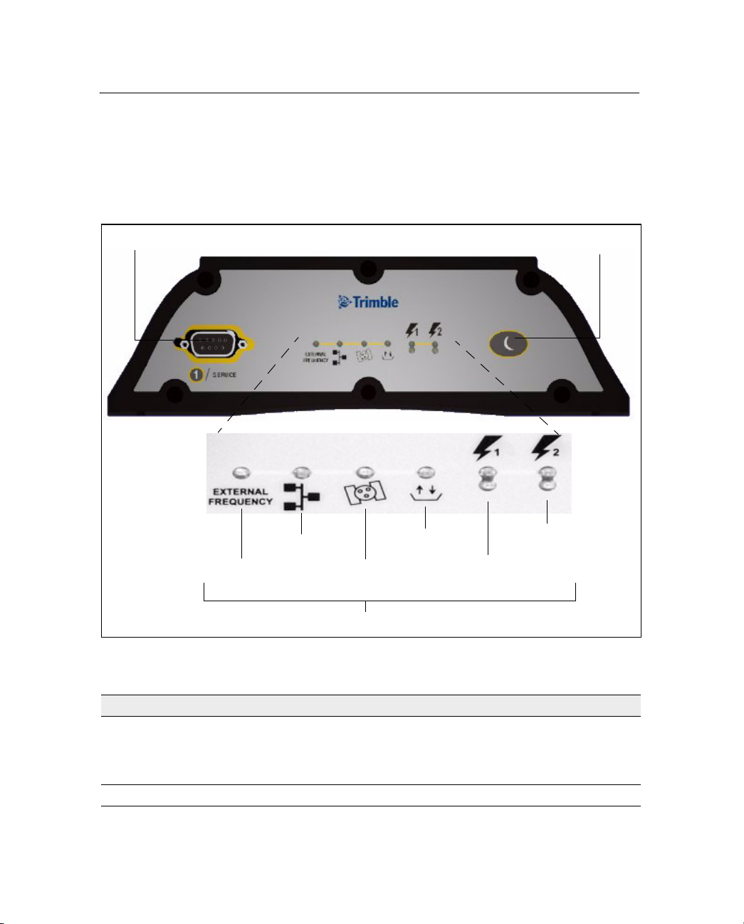
31.1 Front panel
Figure 3.2 shows the features on the front panel. The following tables
describe the features. For more information, see Button Functions,
page 18 and LED Functions, page 22
Features and Functions 3
.
DE9 connector
Ethernet
External
frequency
Figure 3.2 Front panel features
Satellites
LEDs
Logging
Power butto n
Secondary
power
Primary
power
Feature Description
DE9 port Provides a service port for initial Ethernet address configuration and
diagnostics. The service port uses a 3-wire connection with default
parameters of 115,200 baud, 8-NONE-1. Linux diagnostics are
available through this port during the boot and shutdown processes.
Power button Controls the receiver power states
NetRS GPS Receiver User Guide 13
Page 22

3 Features and Functions
LED indicator shows...
External frequency external oscillator activity
Ethernet Ethernet port activity
Satellites satellite tracking status
Logging logging status to the internal memory
Primary power power status on the primary power port
Secondary power power status on the secondary power port
31.2 Rear panel
Figure 3.3 shows the rear panel features. Serial ports can support
RT-17 and BINEX data formats (to stream real-time GPS
observables), and CMR and RTCM data formats (to stream
RTK/differential corrections). Each port can also act as a PPP server
for IP communications over a serial link.
All supported configuration, streaming, file transfer, and firmware
update capabilities are supported over the Ethernet port or any serial
port supporting IP communications using PPP.
14 NetRS GPS Receiver User Guide
Page 23
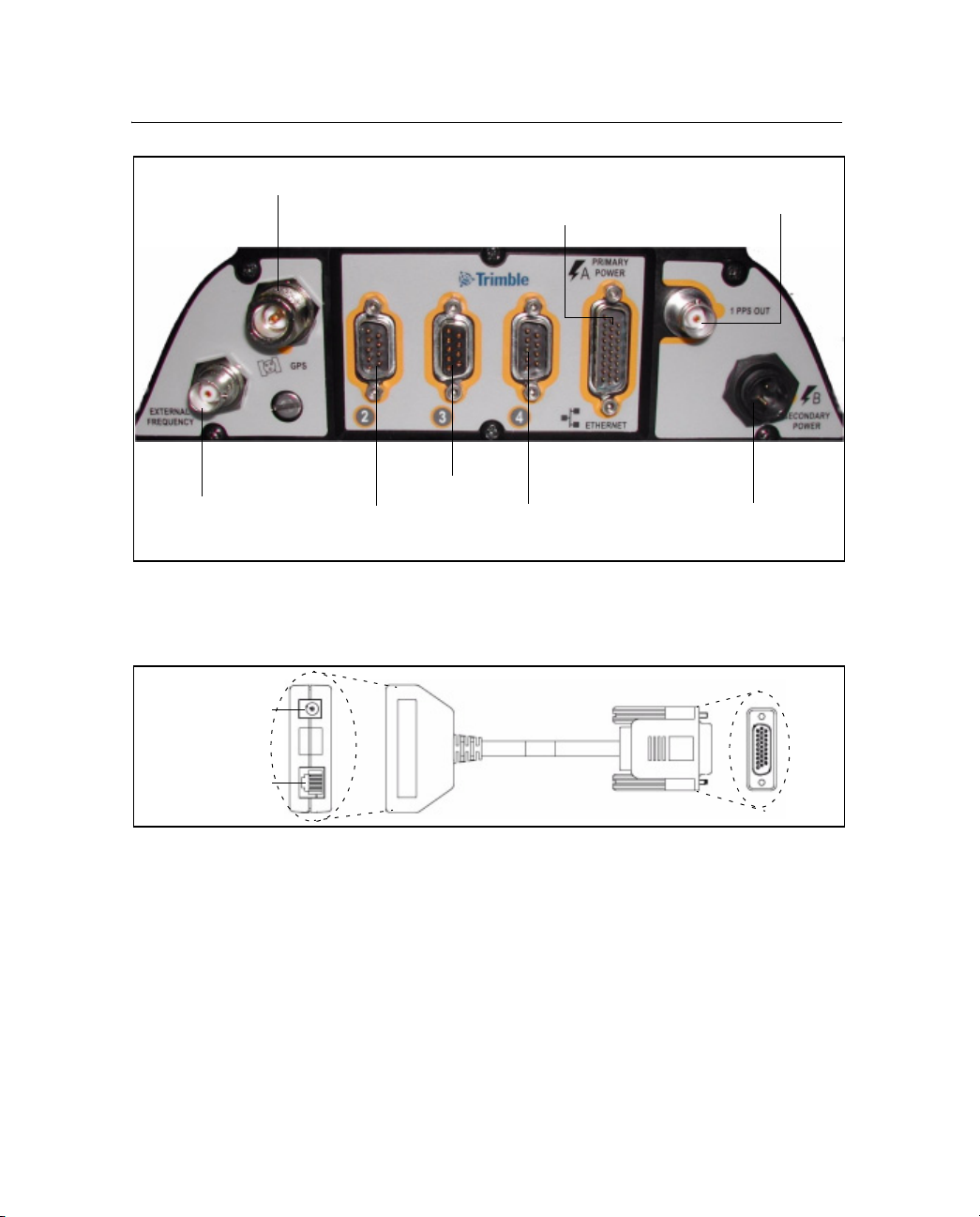
Features and Functions 3
Antenna (N)
External
frequency
(BNC)
Figure 3.3 Rear panel features
Port 2 (DE9 M)
Figure 3.4 shows the multi-port adapter in detail.
.
Power
connection
Por t 3 (DE9 F)
Port 4 (DE9 M)
Multi-port adapter
Primary power /
Ethernet (DA26-M)
1PPS output
(BNC)
Secondary
power (Conxall)
Ethernet
connection
Figure 3.4 Multi-port adapter detail
NetRS GPS Receiver User Guide 15
Page 24

3 Features and Functions
Table 3.1 Rear panel features
Feature Description
N connector Connects to the GPS antenna.
Multi-port adapter
(DA26 male port)
BNC ports (two) One PPS output.
DE9 male ports
(two)
DE9 female port Connects to a DTE device, such as a computer.
Note – The 3 rear panel ports include full 9-pin connections that provide all the signals required to
support a modem or other communications device. A serial port can be configured for either direct or
modem connections. A modem connection supports all the signals necessary for auto-answer operation
using the Linux communication protocol, mgetty daemon. For more information, see Cables and
Connectors, page 73.
Primary power port – AC-to-DC power supply connects through an inline
DC power jack.
Ethernet port – connects to a 10Base-T network through an RJ45 jack.
External frequency input.
Connects to a DCE device, such as a modem or a terminal adapter.
2-pin Conxall
connector
16 NetRS GPS Receiver User Guide
Secondary power port.
Backup battery power connects through a DC power cable (P/N 48600).
Page 25

31.3 Power ports
The NetRS receiver has two power ports:
• Primary – connects to the DA26 connector on the rear panel
through an inline DC power jack on the multi-port adapter.
Intended for use only with the Trimble AC-to-DC power supply
(P/N 48800-00).
• Secondary – connects to the 2-pin Conxall connector through
the DC power cable with polarity indications (P/N 48600).
Intended for battery backup using a nominal 12.6 V lead acid
battery system with any type of charging configuration.
Trimble recommends that you use a minimum 20 Amp-hour lead acid
battery in backup power configurations. A 20 Amp-hour battery will
provide over 60 hours of backup power, or about 30 hours with 50%
derating, if the receiver and antenna are the only powered devices.
If you use an external low voltage disconnect (LVD), set the NetRS
receiver shutdown voltage so that the LVD does not switch off while
the receiver is powering down. Do one of the following:
Features and Functions 3
C
• Set the shutdown voltage to at least 0.3 V above the LVD
disconnect voltage. Trimble recommends this setting to enable
the receiver to shut down normally.
• Set the shutdown voltage to at least 0.3 V below the LVD
disconnect voltage.
A large capacity battery will provide longer backup time. Trimble
does not recommend that you use a small capacity battery. Any battery
charging system must match the selected battery size.
Caution – Do not exceed the power supply voltage specification.
Use only AC power supply (P/N 48800-00) with the NetRS receiver.
NetRS GPS Receiver User Guide 17
Page 26

3 Features and Functions
3.2 Button Functions
The NetRS receiver has only one button, the Power button, which is
on the front panel. The function of this button is to turn the receiver on
(press the button once) and off (press and hold the button for two
seconds). If you turn the receiver off using the
receiver will stay off, regardless of any alarm settings you may have
made. To turn the receiver on again, you must use the
remove and then reapply power to the receiver.
32.1 Power button operations
• When the receiver is switched on and operating, press the
Power button for at least 2 seconds, but not more than 10
seconds, to switch the receiver off. All LEDs, except the
Ethernet LED, turn off briefly when the receiver accepts the
button press.
Power button, the
Power button or
• When the receiver is off, press the
receiver on.
The NetRS receiver requires time to start up and shut down. It
can take from 75 seconds to 4 minutes to fully start up the Linux
operating system, depending on the previous shut down
conditions.
To turn off the receiver, press and hold the power button for two
seconds. The shut down process normally takes between
20 seconds and 1 minute. During these operations, all the LEDs
flash.
Once you have pressed the
to complete before you press the button again.
18 NetRS GPS Receiver User Guide
Power button once to turn the
Power button, wait for the operation
Page 27

32.2 Power saving mode
Use the power saving mode to set options that control whether the
receiver remains on continuously or goes to sleep between data
logging sessions. This feature is particularly useful for sites with
intermittent power or where batteries are used and charging.
Sleep mode
In Sleep mode, the receiver switches to low power when there is no
active data logging session. This allows for extended operation when
the receiver is running on battery power.
Failsafe wakeup alarm
When the receiver is in Sleep mode, you cannot communicate with it
until the receiver wakes up for the next scheduled session. To avoid
problems if there is no future session defined, use the Failsafe wakeup
alarm. This activates the receiver for a short period at specific times
every day.
To control Sleep mode, select Data Logging and then set the following
controls as required in the Power Saving screen or the Status screen:
Features and Functions 3
• Shut down receiver between data logging sessions?
– Select Yes for the receiver to go into the power saving
mode when there are no active sessions. Once the receiver
is in this mode, you cannot communicate with the receiver
or use the browser interface until the receiver wakes up.
– Select No to disable Sleep mode. The receiver remains
active between sessions.
• Wake up periodically?
– Select Yes for the receiver to wake from Sleep mode for a
short time at one or more periodic intervals every day,
regardless of the need for a data logging session. This
option allow you to establish communications with a
receiver when there is no data logging session scheduled.
NetRS GPS Receiver User Guide 19
Page 28

3 Features and Functions
Specify the duration of the wakeup alarm, and the interval
between alarms, from a range of values. The wakeup times
are always synchronized to the beginning of the UTC day.
For example, if you specify an 8 hour interval, then a
periodic wakeup alarm will occur every day at 00:00 UTC,
08:00 UTC, and 16:00 UTC.
C
32.3 Other power operations
Caution – If you turn off the Failsafe wakeup alarm, you may not be able
to communicate with a remote receiver.
Note – If you press Power while the power saving mode is enabled
and the receiver is in Sleep mode, the receiver temporarily turns on. If
there is no session pending, the receiver continues to operate for five
minutes, then automatically shuts down. If you visit the NetRS home
page for the first time during such a “hold off” period, a dialog
appears to warn that the receiver is scheduled to shut down after the
hold off time.
If you press
receiver is on, power saving mode is disabled and the receiver turns
off.
• If you disconnect all power sources, the receiver shuts down. It
• The receiver turns on only if at least one of the power supplies
Powe r while the power saving mode is enabled and the
automatically turns on again when you reconnect a power
source of 12 V or more. The receiver may take longer to boot up
when power is restored after a sudden power loss.
supplies 12 V (or more) power.
However, when the receiver is on battery power, you can turn it
off, or put it into Sleep mode, if the voltage is more than 11 V.
• When you use a standard AC power supply, or a battery that is
providing at least 12 V (that is, charged to at least 40-50% of
capacity), the
switch to boot up or shut down the receiver.
20 NetRS GPS Receiver User Guide
Power button will always function as an on/off
Page 29

32.4 To erase the almanac and the ephemeris
You can erase the almanac and the ephemeris when they are out of
date:
Features and Functions 3
1. Press and hold down the
Power button for 15 seconds. The
External Frequency LED turns on.
2. Once you release the
Power button, the almanac and ephemeris
are erased.
30.1 To reset the receiver to factory defaults settings
C
Caution – The reset operation can take 5 to 10 minutes. Wait until the
receiver has returned to normal operation before you press the Power
button or disconnect receiver power. With the antenna connected, wait
until the Satellite tracking LED blinks to indicate normal tracking.
Alternatively, connect an office computer to the service port and wait until
the diagnostics output displays Switching to runlevel: 5.
The default IP addressing mode is DHCP. If the receiver is configured with
a static IP address, resetting to factory defaults may cause the receiver IP
address to change and result in loss of communications with the receiver
over the Ethernet link.
1. With the receiver switched on, press and hold the Power button
until the External Frequency LED turns on (at 15 seconds) and
then turns off (at 30 seconds).
2. Once the External Frequency LED turns off, release the
button.
The receiver performs a full reset. All parameters, including
GPS orbit and tracking information, are restored to the factory
default values.
NetRS GPS Receiver User Guide 21
Power
Page 30

3 Features and Functions
3.1 LED Functions
The six LEDs on the front panel of the receiver indicate various
operating conditions. An LED that is constantly lit or is flashing
slowly usually indicates normal operation. An LED that is flashing
quickly indicates a condition that may require attention. An LED that
is unlit indicates that no operation is occurring. The possible LED
states are:
LED state Description
Flashing
slowly
Flash
quickly
Blinking LED is on for 1 second every 5 seconds
Off LED is not lit
On LED is continuously lit
31.1 LED startup sequence
LED is on for ½ second and off for ½ second
LED is on for 0.1 second every 0.2 seconds
When the receiver switches on, all LEDs turn on for a few seconds,
flash until the boot up process is complete, then operate normally.
The LED startup sequence shows if the receiver has started
successfully. When you switch on the receiver, the LED startup
sequence is:
1. All LEDs turn on briefly.
2. All LEDs turn off.
3. LEDs operate normally.
If the LEDs do not turn off, it means that the system has failed to start
correctly.
Note – On startup, LEDs flash from 20 seconds to 4 minutes,
depending on the cause of the previous shutdown. Receiver shutdown
due to a sudden loss of power will force a data file system integrity
22 NetRS GPS Receiver User Guide
Page 31

Features and Functions 3
check the next time the receiver is turned on. The time required to
perform the file system check will increase with the number of data
files stored in receiver memory.
The LEDs operate as follows:
External frequency (orange)
LED state Description
On External frequency source is being used
Flashing slowly External oscillator is being used
Off No external frequency source
Ethernet (green)
LED state Description
On Ethernet port is on
Flashing quickly Ethernet traffic is being received
Off Ethernet port is off or disconnected
Satellite (amber)
LED state Description
Flashing slowly Tracking four or more satellites
Flashing quickly Tracking fewer than four satellites
Off Not tracking satellites
NetRS GPS Receiver User Guide 23
Page 32

3 Features and Functions
Logging (yellow)
Note – Normal operation for the NetRS receiver is continuous logging.
There is no LED state to indicate the memory capacity.
LED state Description
Flashing slowly Logging data to the internal CompactFlash card
Off Not logging data
Power management (green and amber)
Green Power LED Description
On Power source is healthy (12 V or more).
Flashing quickly Power source is low (11 V–12 V).
Off No power source.
The unit will always power on.
The unit will continue to operate, but will not wake
up if in sleep mode.
Amber Power LED Description
On Power source is healthy but is not in use
Flashing quickly Power source is low but is not in use
Off No power source
24 NetRS GPS Receiver User Guide
Page 33

30.1 LED flash patterns
Table 3.2 summarizes the LED flash patterns.
Table 3.2 LED flash patterns
Features and Functions 3
Mode External
Frequency
(orange)
Receiver off
Off Off Off Off Off Off
(no power)
Receiver in Monitor
On On On On On On
mode
Receiver in Sleep
Off Off Off Blinking Off Off
mode
Receiver on primary
N/A N/A Flashing
Secondary power
healthy
Logging data
Ethernet port on
Off On
Receiving traffic
Tracking satellites
Power on Port 2 only
Primary power source
N/A N/A N/A N/A Green on Amber
on
Secondary power
supply low
Primary power source
N/A N/A N/A N/A Green
low
Secondary power
source available
Tracking four or more
N/A N/A Flashing
satellites
External frequency in
use
Flashing
slowly
Ethernet
(green)
Flashes
Satellite
(amber)
slowly
Flashing
slowly
Logging
(yellow)
Flashing
Power 1
(green /
amber)
Power 2
(green /
amber)
Green on Amber on
slowly
N/A Off Green on
with
traffic
flashing
quickly
Amber on
flashing
quickly
N/A N/A N/A
slowly
N/A N/A N/A N/A N/A
NetRS GPS Receiver User Guide 25
Page 34

3 Features and Functions
26 NetRS GPS Receiver User Guide
Page 35

CHAPTER
4
Setting Up the Receiver 4
In this chapter:
Q Setup Guidelines
Q Connecting the Receiver to Other Devices
NetRS GPS Receiver User Guide 27
Page 36

4 Setting Up the Receiver
This chapter describes how to set up the NetRS receiver and how to
connect the receiver to other devices.
4.1 Setup Guidelines
Consider the following guidelines when you set up the receiver.
41.1 Environmental conditions
The NetRS receiver has a waterproof housing. However, you should
take reasonable care to keep the unit dry.
To improve the receiver performance and long-term reliability, avoid
exposing the receiver to extreme environmental conditions, such as:
• Water
• Heat greater than 65 °C (149 °F)
• Cold less than –40 °C (–40 °F)
• Corrosive fluids and gases
41.2 Sources of electrical interference
Do not locate the GPS antenna near the following sources of electrical
and magnetic noise:
• Gasoline engines (spark plugs)
• Televisions and computer monitors
• Alternators and generators
• Electric motors
• Equipment with DC-to-AC converters
• Fluorescent lights
• Switching power supplies
28 NetRS GPS Receiver User Guide
Page 37

41.3 Uninterruptible power supply
Trimble recommends that you use an uninterruptible power supply
(UPS) to supply power to the receiver. A UPS protects the equipment
from power surges and spikes, and keeps the receiver running during
short power outages.
For more information, contact your local Trimble dealer.
41.4 Lightning protection
Trimble recommends that you install lightning protection equipment
at permanent sites. Equipment should include a gas capsule lightning
protector in the antenna feed line and appropriate safety grounding. A
static dissipater near the antenna can reduce the likelihood of a direct
lightning strike. You should also protect any communications and
power lines at building entry points. If you use other antennas or
aerials, such as a radio modem that distributes real-time correction
messages, consider protecting those antennas as well. To be
compatible with the receiver voltage output, the antennas should allow
8 V DC to pass through.
For more information, contact your local Trimble dealer, or go to the
following websites:
Setting Up the Receiver 4
• http://www.hubersuhner.com/
• http://www.polyphaser.com/
NetRS GPS Receiver User Guide 29
Page 38
4 Setting Up the Receiver
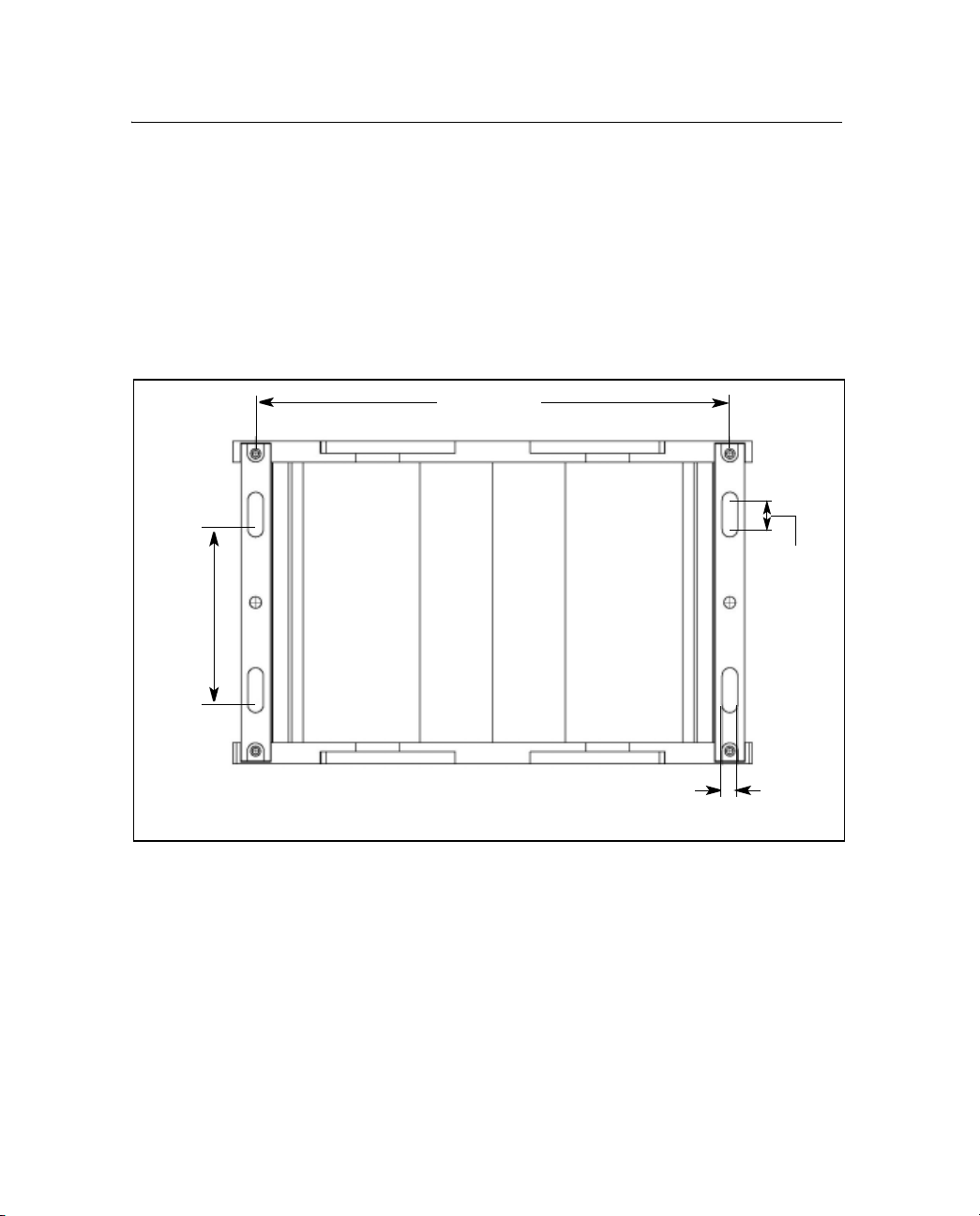
41.5 Mounting the receiver
Figure 4.1 shows the layout and dimensions of the mounting holes on
the base of the receiver.
When you mount the receiver on a vertical surface, use four #10 or M5
threaded fasteners. Thread the fasteners into a solid surface, such as
half-inch plywood or an equivalent solid structure. Make sure the
fasteners are tightly inserted.
76.2 mm
(3 inches)
205.8 mm
(8.1 inches)
12.7 mm
(0.5 inches)
Figure 4.1 Receiver mounting holes
41.6 Placing the antenna
Before you mount the antenna for your reference station, you should
plan the best location for the antenna, and how you will obtain
accurate coordinates for that position.
30 NetRS GPS Receiver User Guide
Back
6.7 mm
(0.3 inches)
Page 39

Setting Up the Receiver 4
Figure 4.2 shows a suitable place for an antenna. Trimble recommends
a site as free as possible from interference, where the antenna has a
clear view of the sky and where there are no obstructions above 10°
elevation.
10°
Figure 4.2 Antenna placement
If there are obstructions above 10°, or large metallic objects nearby,
the rover receiver may collect data from satellites that the reference
station cannot track. This data cannot be used in rover DGPS or RTK
solutions.
4.2 Connecting the Receiver to Other Devices
This section describes how to connect the NetRS receiver to external
devices.
42.1 Antenna
The receiver provides an N-type female connector for connecting to an
antenna. The receiver is intended for use with a Zephyr™ Geodetic or
Choke Ring antenna. However, you can use it with any Trimble
geodetic antenna.
42.2 Antenna cabling
Many permanent GPS installations have unique cabling requirements.
Depending on the available infrastructure, you may need to mount the
antenna a substantial distance from the receiver.
NetRS GPS Receiver User Guide 31
Page 40

4 Setting Up the Receiver
The receiver can withstand a loss of 12 dB between the antenna and
the receiver. The degree of loss in a coaxial cable depends on the
frequency of the signal passing through it.
The following table lists some common types of cable and the
maximum length you can use before you need an inline amplifier
(P/N 33411-00) for GPS frequencies.
Cable type Maximum length
RG-214 30 m
LMR-400 55 m
LMR-500 70 m
LMR-600 85 m
Heliax LDF4/50 105 m
Heliax.LDF4.5/40 140 m
42.3 Met-Tilt sensors
You can connect the NetRS receiver to an external meteorological
(Met) or Tilt sensor.
for use without inline amplifier
The receiver supports only one direct Met-Tilt sensor connection. For
multiple sensors, the solution is to daisy chain. For more information
see Daisy chaining devices, page 33. The sensor responds to a request
for information, and the query and response are time tagged and stored
in any T00 or BINEX file being logged, or transmitted in an RT17 or
BINEX data stream. You can connect a Met or Tilt sensor to any RS232 serial port.
Instruments which can collect meteorological data include:
• Paroscientific MET3 and MET3a (www.paroscientific.com)
• Vaisala PTU200GPS and PTU200GPSMIK (www.vaisala.com)
Instruments which can collect tilt data include:
• Applied Geomechanics D700 and MD900 series
(www.geomechanics.com)
32 NetRS GPS Receiver User Guide
Page 41

Daisy chaining devices
Typically, when you need to collect meteorological and tilt sensor
data, you can connect both devices to one RS-232 serial port.
To do this, use custom cabling where the transmit data (TXD) RS-232
line from one sensor is connected to the receive data (RXD) RS-232
line of the next sensor.
The receiver sends a command to the first device in the chain. Each
device responds to a specific address. If the command is addressed to
the device, the device sends a measurement response to the next
device in the chain. If the command is not addressed to that device, the
command is transmitted without modification, and the next device
may process it. The receiver receives and logs the response from the
last device in the chain.
For more information, see Configuring Met-Tilt sensors, page 47.
42.4 Dial-up modems and terminal adapters
The NetRS receiver provides auto-answer support for a dial-up
modem or a terminal adapter connection as a PPP server. You can
configure the modem, or the receiver can program the AT setup
strings. The receiver can also make automated dial out connections to
an Internet service provider using PPP dial out.
Setting Up the Receiver 4
Note – This option only supports a 24/7 continuous connection for
streaming connections. For more information, refer to the Help.
For full control, a modem must be connected to one of the serial ports
on the rear panel. Typically, this would be port 2 or port 4, which
provide connectors for a DCE device.
You can access and control the receiver over a PPP link. You can also
set up a streaming service, such as Trimcom, CMR RTK, or RTCM
RTK corrections on a serial port. For a streaming service, the modem
must perform the auto-answer function.
For more information, see Dial-up modem, radio modem, or terminal
adapter, page 45.
NetRS GPS Receiver User Guide 33
Page 42

4 Setting Up the Receiver
42.5 Radio modems
The most common data link for Real-Time Kinematic (RTK)
surveying is a radio. You can connect the receiver to an external radio
through one of the four serial ports, whether or not the Ethernet port is
in use. Typically, use one of the DE9 male ports on the rear panel.
The NetRS receiver supports the following Trimble base radios:
•TRIMMARK™ 3
• TRIMMARK IIe
• PDL450
• TRIMTALK™ 450S
To use an external radio with the NetRS receiver, you need an external
power source for the radio. Use the external radio’s configuration
program to configure the radio modem separately.
To configure the receiver for RTK operation, you must do both of the
following:
• Enable the RTCM or CMR RTK corrections stream on the
selected serial port.
• Set the reference station coordinates and broadcast ID.
For more information, see Chapter 5, Configuring the Receiver.
42.6 External frequency reference
Use a BNC cable to connect to an external frequency reference. The
receiver directly supports a 10 MHz external frequency reference.
An external reference must provide the reference signal with an
amplitude in the range +6 to +13 dBm, and a frequency tolerance
within +/- 5 ppm over temperature and time.
You can also use one of the following external off-the-shelf adapters to
support a 5 MHz or a 20 MHz external reference source with a +7 to
+13 dBm input range:
• 5 MHz: Wenzel LNHD HF DOUBLER
(Wenzel P/N 601-10726 Rev. A)
• 20 MHz: Wenzel LNFDN FREQUENCY DIVIDER
(Wenzel P/N LNFDN-2-20-10-1-10)
34 NetRS GPS Receiver User Guide
Page 43

CHAPTER
5
Configuring the Receiver 5
In this chapter:
Q Setting up Communications
Q Configuring the Receiver Through a Web Browser
Q Configuring the Receiver for Connected Devices
Q Updating the Receiver Firmware
NetRS GPS Receiver User Guide 35
Page 44

5 Configuring the Receiver
The NetRS receiver typically communicates through a network such
as the Internet. To configure the receiver, access files, and update the
receiver firmware, you must create an IP-based link to the receiver.
This chapter describes how to connect the receiver to a network,
configure the receiver through the HTTP web interface, configure the
receiver for a connected device, and install new firmware.
5.1 Setting up Communications
Connect the receiver to a network or host computer through one of the
following:
• The Ethernet (10Base-T) port
Use a CAT5 cable to connect the receiver to a network hub or
switch. Alternatively, use a crossover cable to connect directly
to the receiver from a host computer.
• A PPP connection from a serial port
For more information, see Setting Up a PPP Connection,
page 83.
The NetRS ethernet port supports 10Base-T full duplex and autonegotiation. The system automatically configures to the highest
interoperable performance mode. Possible modes and configurations
are as follows:
Ethernet port mode System configuration
1: 10Base-T full duplex NetRS receiver and End port devices support auto-negotiation
End port device is configured for full duplex
2: 10Base-T half duplex NetRS receiver and End port devices support auto-negotiation
End port device is configured for half duplex
3: 10Base-T half duplex The NetRS receiver supports auto-negotiation
End port device does not support auto-negotiation
or
There is no ethernet port connected
36 NetRS GPS Receiver User Guide
Page 45

Note – Do not configure a NetRS receiver in mode 3 where the End
port device does not support auto-negotiation but the receiver is
configured for “full duplex” instead of “half duplex”. If you do, you
may encounter Ethernet data overflows and system problems.
1. To configure initial parameters for a hub- or switch-based
connection, use Port 1 on the receiver front panel.
2. To complete the configuration, access the web-based
configuration pages.
50.1 Configuring the Ethernet connection
To configure a 10Base-T connection, you need the following:
• A terminal emulator on the host computer that you will use to
configure the receiver.
• One of the following:
– A static IP address, default gateway, and netmask for a
static configuration.
Configuring the Receiver 5
If you use a crossover cable for the connection, then you
can use any address that does not conflict with the IP
address and default gateway address of the connected host.
– A DHCP server on the network.
• A 10Base-T network connection and a CAT5 cable.
Connect through a port on a network hub or switch that is also
connected to the host computer that you will use to configure
the receiver.
Alternatively, use a crossover cable to connect directly to the
host computer.
NetRS GPS Receiver User Guide 37
Page 46

5 Configuring the Receiver
To define a static IP address for the device or to obtain
network-assigned DHCP parameters:
1. Use a standard RS-232 cable to connect a computer host to the
receiver service port.
2. Configure a terminal emulator program (for example,
Hyperterminal for the Windows operating system) for a 115,200
baud 8-N-1 connection with no hardware flow control.
If you use Hyperterminal:
B
a. Click
Disconnect.
b. To set the parameters, select File / Configure and then click
Configure.
c. Change the communication values and then click
Tip – You may also want to enable the terminal emulator to capture text for
future review.
Connect.
3. Connect or supply power to the receiver. If the receiver is
already turned on, turn it off and then on again.
As the receiver starts, it emits diagnostic information through
the service port. For example, Figure 5.1 on page 39 shows the
summary sequence that appears when you define a static IP
address configuration.
4. When the message
Do you want to change Ethernet Configuration?
appears, enter yes.
5. Enter the new mode, static IP address, default gateway address,
and netmask. Press
Enter.
The new values appear in the summary followed by the message
Accept New Configuration?.
6. If the new values are correct, enter
38 NetRS GPS Receiver User Guide
yes.
Page 47

Configuring the Receiver 5
Current Ethernet Port Configuration:
MAC address: 00:60:35:00:C3:12
Mode: dhcp
IP: 0.0.0.0
Netmask: 255.255.255.0
Gateway: 0.0.0.0
Do you want to change Ethernet Configuration? (yes|no)[no]: yes
New Mode (static|dhcp): static
New static IP Address [0.0.0.0]: 10.1.80.74
New Gateway Address [0.0.0.0]: 10.1.80.1
New Netmask [255.255.255.0]: 255.255.254.0
New Configuration
Mode: static IP
IP: 10.1.80.74
Gateway: 10.1.80.1
Netmask: 255.255.254.0
Accept New Configuration? (yes|no)[yes]: yes
Accepted - Updating configuration files
Applying new Network configuration
Figure 5.1 Ethernet port configuration sequence
Note – If you do not have a pre-assigned static IP address but you do
have DHCP services on your network, you can enter
dhcp as the
Ethernet address mode. To obtain the automatically assigned IP
address, monitor the service port output as the receiver boots up.
NetRS GPS Receiver User Guide 39
Page 48
5 Configuring the Receiver
Changing the Ethernet configuration
After you configure the receiver as described in the previous section,
you can change the Ethernet address configuration or add Domain
Name System (DNS) information (the IP address of one or more DNS
servers, a domain name, and a domain search path). You can make
these changes from the Ethernet configuration screen.
Once you have the receiver IP address, open the required web pages
and complete the network configuration as follows:
1. From a host computer with a network connection to the
receiver, open a web browser, such as Internet Explorer or
Netscape.
2. In the URL address field of the browser enter
http://, followed by
the IP address of the NetRS receiver. For example, to access the
receiver web server home page for the configuration in
Figure 5.1, enter
http://10.1.80.74.
Note – You must configure your web browser to bypass any
proxy server in use for the connection to the NetRS receiver.
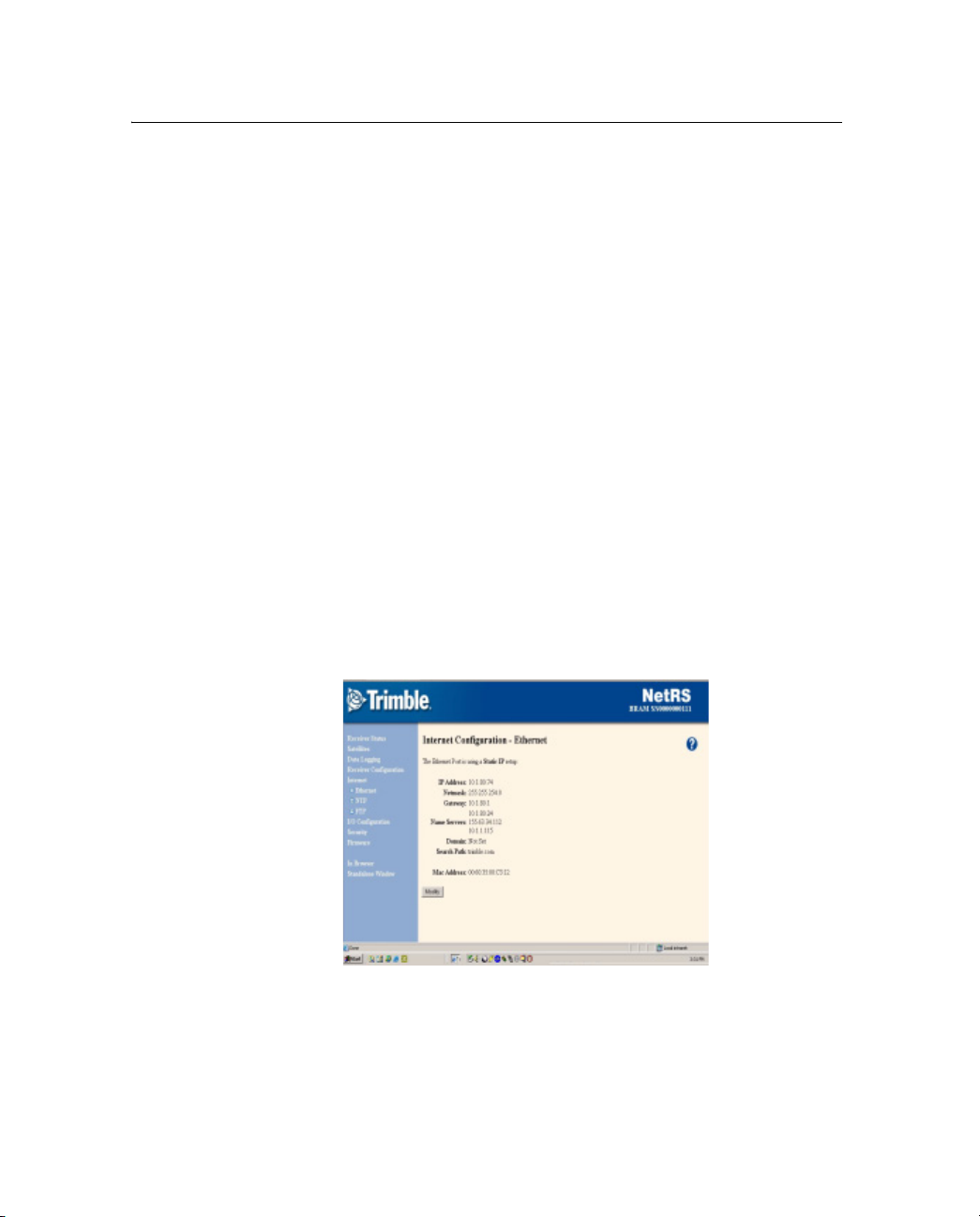
3. From the NetRS main menu, select Internet. The Internet
Configuration – Ethernet screen appears:
4. Click
Modify. In the Ethernet Configuration screen that
appears, change the existing IP address configuration or enter
DNS information as required.
40 NetRS GPS Receiver User Guide
Page 49

Configuring the Receiver 5
5.1 Configuring the Receiver Through a Web Browser
This section briefly describes the interface that you use when you
access the receiver through a web browser. You can configure the
receiver through the Ethernet port or through a serial port that provides
a PPP link to the receiver.
51.1 Web-based menu
The following table briefly describes options in the NetRS web-based
menu system. For more information, refer to the NetRS Help. To
access the help, click .
Table 5.1 Web-based menu options
Main menu
option
Receiver
Status
Satellites View a summary of current satellite activity.
Data Logging View and manage logging sessions.
Use the sub-menu screens to ...
View basic parameters, such as system name, IP address, and firmware
version.
Modify the system name.
View a list of the SVs being tracked, files being logged, a list of currently active
streams, power supply voltages, and the receiver internal temperature.
View the currently computed GPS position, DOP, and clock offset.
View a detailed table of current satellite activity.
Enable or disable individual satellites.
Control and configure the receiver for WAAS.
View a text version of the almanac, ephemeris, UTC time, and ionospheric
model data broadcast by GPS satellites.
Manage file space through the Automatic File Deletion mode.
Shut down the receiver between sessions.
Set the wakeup alarm.
View logged data files.
Access and download logged files.
For more information, see Chapter 6, Logging and Managing Data.
NetRS GPS Receiver User Guide 41
Page 50

5 Configuring the Receiver
Table 5.1 Web-based menu options (continued)
Main menu
option
Receiver
Configuration
Use the sub-menu screens to ...
Access global receiver controls, including antenna settings, clock steering,
multipath control, masks, and 1 PPS.
Enable the external reference.
Manage and apply receiver configuration files.
Copy a configuration from one receiver to another.
Restore the configuration of a receiver.
Configure a voltage threshold for automated receiver shutdown in case of low
battery power.
Clear all GPS almanac or ephemeris information.
Reset (restart) the receiver.
42 NetRS GPS Receiver User Guide
Page 51

Table 5.1 Web-based menu options (continued)
Configuring the Receiver 5
Main menu
option
Internet Configure the Ethernet connection.
Use the sub-menu screens to ...
Configure the MTU value to limit the maximum packet size sent over the
network by the NetRS receiver. Where network communications are slow or
there is significant data loss it may be better to decrease this value.
Enable/Disable the HTTP and/or HTTPS ports.
Select alternative HTTP/HTTPS ports. HTTPS sends encrypted data from the
browser client to the receiver, which makes HTTPS more secure than HTTP,
especially if the receiver is not installed behind a network firewall.
Setup IP filtering to allow access only from specified IP addresses.
Limit access to the receiver by specifying a range of IP addresses that are
authorized to connect to the receiver. The receiver will not respond to attempts
to connect from a non-specified IP address.
Note – You must specify valid IP addresses. If the specified IP addresses do not match
at least one of those used to connect to the NetRS receiver, you will not be able to
communicate with the receiver.
Configure FTP access policies, including passwords for named FTP accounts.
Change, or enable and disable, the default FTP ports.
Control access for anonymous FTP, named account data files, and system files
(for firmware upgrades).
Configure the receiver for one or more NTP servers.
Send notification messages to selected computers on a network with
information about the available services and the ports on which those services
are enabled.
For more information on FTP access for logging data, see Chapter 6, Logging
and Managing Data.
For more information on FTP access for updating the firmware, see Updating
the Receiver Firmware, page 49.
NetRS GPS Receiver User Guide 43
Page 52

5 Configuring the Receiver
Table 5.1 Web-based menu options (continued)
Main menu
option
I/O
Configuration
Security Control web-based access to the receiver. Access levels include System
Firmware Upload and install new receiver firmware and additional extended warranties.
In Browser /
Standalone
Window
Use the sub-menu screens to ...
Control serial port and TCP/UDP/REP port configurations and services
(including PPP, GPS data streaming, and RTK correction services).
Define the precise station position, station ID, and the station name used for
RTK correction streams.
Set up the client authentication password to secure the datastreams for use
only by authorized personnel.
Port advertising so the receiver can advertise to a specified IP address what
services it offers and on which ports.
PPP Dialout can be used to dial out to an ISP (Internet Service Provider) to
initiate a connection directly from the receiver.
For more information, see Configuring the GPSBase or GPSNet software,
page 48.
Controls (IP and firmware modification), GPS Controls (GPS tracking and data
logging access), and File Access (restricts web-based access to internally
logged files).
Control the appearance of the browser window. The In Browser and
Standalone Window options do not relate to the operation of the NetRS
receiver. The default mode is In Browser, where all screens include browser
menus and toolbars.
If you prefer to have more screen area available to view and manipulate the
NetRS web pages, select Standalone Window. A new window appears with
menus and toolbars hidden. You can close the Standalone Window and return
to the default view when you want to.
44 NetRS GPS Receiver User Guide
Page 53

Configuring the Receiver 5
5.2 Configuring the Receiver for Connected Devices
This section describes how to configure the receiver to operate with
different types of external devices.
52.1 Dial-up modem, radio modem, or terminal adapter
You can use a dial-up modem, a radio modem, or a terminal adapter
(TA) to support PPP access to full receiver services or access to a fixed
raw data stream, such as RT17 GPS data or RTK corrections.
Typically, you would connect a modem or TA to a DE9 male port on
the rear panel.
Note – The front panel DE9 female port provides only a 3-wire
connection, so flow control is not available through this port.
Make sure that you identify the configuration settings required for the
external device. These include the DCE baud rate and hardware flow
control. Consider the following issues when you define modem or TA
configuration strings:
• A radio-modem must be fully pre-configured.
• If the modem or TA is to be used for a PPP connection, you can
preconfigure the modem or you can enter the setup strings in the
configuration page. See Configuring a modem or terminal
adapter, page 46.
• To configure the modem to Auto-answer mode, you can do one
of the following:
– Select Direct connection type.
– Select Modem connection type to allow the receiver to
manage auto-answer. See Step 6 below.
• If you are using a modem or a TA for RT17 data or RTK
correction streaming, then you must do all of the following:
– Fully configure the modem before you connect it to the
receiver.
NetRS GPS Receiver User Guide 45
Page 54

5 Configuring the Receiver
– Enable Auto-answer mode in the modem.
– Use hardware flow control.
– Program the modem to use RTS to hold off data when there
Note – For flow control, always use a rear panel DE9 port.
Configuring a modem or terminal adapter
1. From the NetRS main menu, select I/O Configuration.
2. Select the serial port to configure.
3. If you are using a PPP server connection, select PPP:
4. Select the baud, parity, and flow control.
5. If required when configuring the PPP service, enter the local
and remote IP addresses.
6. Select the required connection option:
– Modem – to enable the receiver to manage the auto-answer
is no active connection.
operation. Use this option for a PPP connection.
– Direct – if the modem is configured for auto-answer.
7. If you are providing RT17, RTCM, or CMR data:
a. Select the required service.
b. Enter the appropriate port and define the service
parameters.
When you configure RTCM or CMR RTK corrections,
configure the ports as described in RTCM or CMR
corrections, page 49.
46 NetRS GPS Receiver User Guide
Page 55

50.1 Configuring Met-Tilt sensors
All communication with Met-Tilt external sensors is by ASCII strings
through a receiver serial port. The NetRS receiver supports the
following forms of command strings to configure and query an
external sensor:
• Initialization – The receiver sends an initialization string to the
sensor at the beginning of every survey session. The string may
include calibration parameters to configure the external sensor.
In most cases, only device query operations are performed, and
an initialization string is unnecessary.
• Query – The receiver sends a query string at a predefined
interval for each device to request a new measurement. Each
time the receiver sends a query string, the system assigns a GPS
time tag and logs the measurement.
You can configure this service to send one or more initialization and
repeat strings (up to a total of six strings) on a regular basis to obtain
measurements from external sensors. These sensors include those used
to collect meteorological data and/or deformation data (where the tilt
of the sensor is measured). The time tag, query string, and the
response from the sensor(s) are then stored in all Trimble T00 or
BINEX files that are being logged in the receiver, and are also sent out
through any ports that are configured for streaming RT17 or BINEX
GPS measurements.
Configuring the Receiver 5
Configuring the receiver to use an external sensor
1. Select the I/O Configuration, then the Port Configuration screen
and then select the Met-Tilt check box.
2. In the Parameters for Met-Tilt group, specify the command to
send. You do not need to include a carriage return or new line
character.
For example, a typical Met sensor command appears as:
*0100P9
NetRS GPS Receiver User Guide 47
Page 56

5 Configuring the Receiver
3. From the Schedule drop-down list, select the interval at which to
send the command.
Select Once to send the command once at the start of every data
logging session.
If you specify query commands that occur at the same time, a
delay of 10 seconds is added to each subsequent command to
avoid possible conflict when sensors are connected serially.
50.1 Configuring the GPSBase or GPSNet software
You can configure the GPSBase or GPSNet software using a Trimcom
or an RT17 service.
Trimble recommends that you use Trimcom to obtain full bidirectional
communications with GPSNet, in preference to streamed RT17.
• Trimcom – Use only a TCP port through an Ethernet or a PPP
link. For dial-up access, you must configure a PPP dial-up link,
as described in Configuring a modem or terminal adapter,
page 46.
• RT17 – Use a serial port or a TCP port.
A default Trimcom service is defined on port 5018. The default RT17
service is at 5017. To change this configuration:
1. From the I/O Configuration screen, select Edit Port Setups.
2. From the drop-down list, select TCP Port 5018. Click
3. To restore the service with a different port value, select Create
New TCP Port from the I/O Configuration screen.
Note – There may be only one Trimcom service running.
4. Configure the parameters as required.
48 NetRS GPS Receiver User Guide
Delete.
Page 57

RTCM or CMR corrections
RTK corrections can stream to a serial port or through a TCP/IP port.
Before you create the service:
1. From the I/O Configuration screen, select Reference Station.
2. Enter the precise station coordinates and the station ID/name to
be used.
To create an RTK service:
1. From the I/O Configuration screen, select the required serial
port or select Create New TCP Port.
2. If you are creating a TCP/IP port, enter the port number.
3. Select and configure an RTCM or a CMR service.
For more information on RTCM and CMR options, refer to the
online help.
5.1 Updating the Receiver Firmware
Configuring the Receiver 5
The firmware update release is a complete, self-installing, firmware
package. It is assembled using the Red Hat Package Manager (RPM)
for Linux.
If you are an eligible and registered customer, you will receive an
e-mail when a firmware upgrade is available for the NetRS receiver.
To obtain the firmware upgrade files, go to www.trimble.com.
Download the NetRS firmware to your computer, then use the web
browser to install it on the NetRS receiver. Alternatively, log in as
“adminFTP” and transfer the update through FTP. You can then install
the new firmware over HTTP.
NetRS GPS Receiver User Guide 49
Page 58

5 Configuring the Receiver
51.1 Downloading the firmware upgrade
1. In the advisory e-mail, click the URL link.
Alternatively, enter or paste the URL into the web browser
address field.
2. If a download dialog appears, choose to save the file to your
local hard disk.
The version number of the release is embedded in the file name.
It represents a naming format that guarantees unique file names
for subsequent firmware release packages. Do not change this
file name.
50.1 Uploading the firmware
1. From the NetRS main menu, select Firmware / Upload. A
screen appears.
2. Click
Browse. A dialog appears.
3. Find the RPM file that you downloaded to your system from the
Trimble website.
4. Select the RPM file and then click
The full RPM file is approximately 12 MB in size. It may take more
than 30 minutes to transfer across a slow link, such as a PPP link over
a modem connection. From time to time, smaller releases will be
available.
The system displays a dialog once the file is successfully transferred.
If the transfer fails, an error message appears.
50.1 Installing the firmware upgrade
1. Click Install next to the firmware description.
Alternatively, click
Install next to each firmware file line item at
the top of the page.
50 NetRS GPS Receiver User Guide
Upload.
Page 59

Configuring the Receiver 5
2. In the confirmation pop-up that appears, click OK to begin.
While the upgrade is in progress, the screen is not available. The
web browser may display an error dialog to advise that the web
server is unavailable. Wait five minutes.
Note – To monitor the upgrade operation, connect to the front
panel service port at 115200-8-N-1, using a terminal emulator
such as Hyperterminal.
The receiver reboots and installs the new firmware.
Once the receiver reboots again, the upgraded firmware will be
operational. Normal LED function resumes.
3. After several minutes, the screen times out. Click
Reconnect.
NetRS GPS Receiver User Guide 51
Page 60

5 Configuring the Receiver
52 NetRS GPS Receiver User Guide
Page 61

CHAPTER
6
Logging and Managing Data 6
In this chapter:
Q Data Logging Sessions
Q Data Format
Q Naming Files
Q Managing Files Through the Web Interface
Q Managing Files Using FTP
NetRS GPS Receiver User Guide 53
Page 62

6 Logging and Managing Data
Use the NetRS receiver to log data to the internal CompactFlash card.
You can then access the data directly from the receiver, or publish it on
a company intranet or on the Internet.
The CompactFlash card has the following approximate storage
capacity for logged data files:
• 150 MB (256 MB card)
• 900 MB (1 GB card)
The following table shows in days the amount of data that you can
store:
Card Interval
seconds
0.1 2 1 1
1.0 19 14 12
256 MB
1GB
6.1 Data Logging Sessions
5.0 74 57 46
15.0 173 136 112
30.0 291 237 200
0.1 12 6 6
1.0 114 84 82
5.0 444 342 276
15.0 1038 816 672
30.0 1746 1422 1200
A data logging session is the process that creates a data file. To log
information to a data file, you must first create a session, then enable
the session. You can create multiple session definitions for different
purposes. These sessions can simultaneously log different types of
data on different schedules into separate files. Sessions can run
automatically, using one of several scheduling modes.
6 SVs 8 SVs 10 Svs
54 NetRS GPS Receiver User Guide
Page 63

Logging and Managing Data 6
A session runs automatically only if you have enabled a session. This
allows you to define multiple sessions in the receiver, with
independent characteristics, but run them only when required. For a
Manual session, select the Enable check box to start or stop the
session.
You can define one or more sessions, then enable some, all, or none of
them. This allows you to define multiple modes of data logging in the
receiver, then enable any particular mode(s) as required.
Note – Be sure to use a different session identifier for any session that
will create files with the same start time as another session.
More than one session can be active at the same time. The receiver
records a separate data stream for each session.
While there is no limit on the number of sessions you can create, you
can have only eight sessions actively logging at any one time. If you
define more than eight sessions, you can enable up to eight but you
must disable all others.
The following table describes the available schedules.
Schedule Description
Manual Manually controlled start and stop time.
Once Only Single session with a starting date, time, and duration.
Creates a single file.
Daily Repetitive session with a fixed time and duration every
day.
Creates a fixed-duration file each day.
Continuous
Logging
Once started, this session runs continuously, 24 hours a
day.
Creates multiple files of the specified durations.
Continuous logging is the most common mode used for CORS
operation.
NetRS GPS Receiver User Guide 55
Page 64

6 Logging and Managing Data
61.1 Creating or editing a session
1. From the NetRS main menu, select Data Logging.
2. In the Data Logging Status screen, select Create a New Session,
or Edit Sessions.
3. Configure the new session, or change an existing session, as
required.
60.1 Enabling a session
To enable a session, select the Data Logging screen, then the Status
scree and then select the Enable check box.
60.2 Disabling a session
To disable a session, clear the Enable check box.
6.1 Data Format
The T00 data format provides control over position and measurement
logging rates and whether Code or Carrier phase smoothing is
enabled.
The receiver can also log data in the UNAVCO BINEX format. For
more information, go to http://binex.unavco.org/. You can enable
carrier phase smoothing for BINEX files.
6.2 Naming Files
Filenames are generated in the form:
StationIDYYYYMMDDHHmmS.ext
For example:
TNCO_NetRs200306052041b.t00
56 NetRS GPS Receiver User Guide
Page 65

The elements in the filename are as follows:
Element Description
StationID The system name, as defined by the GPS network
YYYY The Julian calendar year
MM The Julian calendar month
DD The Julian calendar day
HH The UTC hour when logging started
mm The UTC minute when logging started
S Any letter (a–z) that you define as a session identifier
62.1 Auto Delete
If you select the Auto Delete check box, the receiver automatically
deletes the oldest logged files, as required, to make room for new files.
If you clear the Auto Delete check box, the receiver stops logging data
once the available file space is full. This option affects all files.
You can also set up session pools to define a maximum amount of
memory to be used by each session.
Logging and Managing Data 6
administrator
If auto delete is… when the pool is full…
Enabled the oldest files are automatically overwritten
Disabled the session stops logging data
Each pool can have auto delete enabled or disabled.
NetRS GPS Receiver User Guide 57
Page 66

6 Logging and Managing Data
6.3 Managing Files Through the Web Interface
Use the web browser interface to manage logged data files that have
been recorded and are still stored on the NetRS CompactFlash card.
63.1 Storing files
Data that has been logged by the NetRS receiver is stored and
organized into files in a directory (folder) tree structure. Select the
Data Logging screen and then the Logged Data Files screen to view
and manage these files:
The Logged Data Files screen displays one directory at a time, starting
at the root directory (/). To navigate to another directory, click the
directory name in the list.
To move up from the subdirectory toward the root directory, click the
parent directory link.
Directory contents
Each directory title shows the directory path. This is followed by a
table that shows the directory contents. All subdirectories are listed
first, along with the date and time that the contents of that subdirectory
58 NetRS GPS Receiver User Guide
Page 67

were last modified. Then, all of the data files are listed. Each list
shows the name of the file, the date when it was last modified, and the
file size in bytes.
Note – The modification time is not when the file was created. It refers
to the most recent time when data was written to the file, which is
usually the time that the data logging session ended.
63.2 Sorting files
To sort the directory list, click a column heading. For example, click
Name to sort the list by file or directory name, or click Modified to sort
by the modification date, from earliest to latest. The selected column
heading appears in bold. Click the column heading again to reverse the
order of sorting. Regardless of the sorting method, all directories are
listed first, followed by the data files.
63.3 Downloading files
To download a file to the computer running your web browser, click
the icon or name of a data file. An Open or Save dialog appears. When
prompted, enter the directory and file name. Once you click
equivalent button), the download begins. While downloading a file, the
browser displays a progress dialog.
Logging and Managing Data 6
OK (or the
63.4 Deleting files
To delete a data file:
• Click next to it.
To delete all files and subdirectories:
1. Go to the end of the file list.
2. Click on the line “Delete ALL FILES AND
SUBDIRECTORIES in this directory.”
NetRS GPS Receiver User Guide 59
Page 68

6 Logging and Managing Data
6.1 Managing Files Using FTP
To list, download, or delete logged data files from the data logging
memory, use any standard FTP client. NetRS FTP access must be
enabled for the given function. Select the Internet screen and then the
FTP Setup screen to define FTP access policies and passwords and to
change the default FTP port:
For Anonymous and Named FTP, make sure that you enable or disable
access to the File deletion option as required.
The receiver provides three options for FTP transfer:
• Anonymous FTP – log in as “anonymous” or “ftp”
• Named FTP – log in as “netrsFTP”
• Administration FTP – log in as “adminFTP”
60 NetRS GPS Receiver User Guide
Page 69

Logging and Managing Data 6
Administration FTP (for the system administrator) is normally used
only for installing and managing firmware. Trimble recommends that
you do not manage logged data from this account. To access logged
data through FTP, users or automated clients would normally use
Anonymous FTP or Named FTP.
Files are created in subdirectories as specified for each session. Each
session has a session identifier character. For more information, see
Naming Files, page 56.
The directory naming options support moderate sized directories using
the default YYYYMM naming scheme. They also support detailed
directory structures using the day and/or session identifier. When you
use this default scheme, you can navigate the FTP directory quickly
and easily.
To access the files remotely through FTP, navigate the directory path
to the required timeframe, then transfer and/or delete files as required.
FTP sessions always start at the root of the logging hierarchy, under
which you will find all directories with YYYYMM naming.
Note – You can transfer only those files that end in .T00 or .BNX. Any
file opened for an active logging session will end in .T00.A or .BNX.A.
Do not attempt to transfer those files.
NetRS GPS Receiver User Guide 61
Page 70

6 Logging and Managing Data
62 NetRS GPS Receiver User Guide
Page 71

CHAPTER
7
Real-Time Data and Services 7
In this chapter:
Q Streamed Data Services
Q Collecting Data as a Client
NetRS GPS Receiver User Guide 63
Page 72

7 Real-Time Data and Services
This chapter describes the streamed data services, and how a client can
collect real-time GPS data.
7.1 Streamed Data Services
The NetRS receiver supports five streamed data services: RT17,
Trimcom, BINEX, CMR (CMR+), and RTCM.
71.1 RT17
An RT17 service provides GPS observations, ephemerides, and other
information, as defined for that service. When a client connects to the
service, all data flow is from the receiver to the client.
An RT17 service can have any number of clients. The client can be
considered “passive”, because it does not initiate the data stream and
has no control over its content. The client cannot request any further
information through the TCP connection.
You can configure the receiver for one or more of the Ephemerides,
SV Flags, and Almanacs services on different TCP ports. To request
updates to ephemeris and other information, a client of an RT17
service can open additional TCP sessions while the NetRS receiver
receives and logs the primary RT17 data.
An RT17 service can be used if there are multiple clients requiring the
same streamed data, or when a client is unfamiliar with the Trimcom
protocol.
71.2 Trimcom
With the Trimcom service, the client uses a subset of the standard
Trimble TRIMCOM™ binary communications interface to request
ephemeris and time updates, and other data. The client must first
enable an RT17 stream on this connection using Trimcom commands
to control the data rate, and the rate and content of the data stream.
The client can also send a query for additional information.
64 NetRS GPS Receiver User Guide
Page 73

The Trimcom client must be “active” to enable the data stream. There
can be only one Trimcom service defined on the receiver, and only one
client can use this service at a time.
The Trimble GPSBase and GPSNet applications are the most common
clients of the Trimcom service when active links are required.
Alternatively, they may operate as a “passive” client to an RT17
stream.
71.3 BINEX
The BINEX service provides GPS observations, ephemerides, and
other information that you select. For full information on each
message type, go to the UNAVCO website at http://binex.unavco.org/.
71.4 CMR
The Trimble proprietary CMR service offers RTK users a compressed
data format to work with when using RTK.
Real-Time Data and Services 7
71.5 RTCM
The RTCM service (using format 2.1, 2.2, 2.3) is an alternative
method for sending data to users in the field. It allows compatibility
with non-Trimble rover receivers.
NetRS GPS Receiver User Guide 65
Page 74

7 Real-Time Data and Services
7.2 Collecting Data as a Client
To access GPS data from an RT17 or BINEX service, the client simply
needs to know how to open a TCP connection to the receiver. The
RT17 data is Trimble proprietary, while BINEX format description is
open and described on the UNAVCO website.
To access GPS data from a Trimcom service, the client must know the
binary commands used to enable data streaming. This service is
intended primarily for use by GPSBase and GPSNet software. The
Trimcom command set is a Trimble proprietary format.
66 NetRS GPS Receiver User Guide
Page 75

CHAPTER
8
Other System Information 8
In this chapter
Q Default Settings
Q Specifications
Q Cables and Connectors
Q 1PPS Output
Q Deployment Issues
Q NetRS Support Software
Q Setting Up a PPP Connection
NetRS GPS Receiver User Guide 67
Page 76

8 Other System Information
Default Settings 8.1
The following table shows the default settings for the NetRS GPS
receiver:
Setting Default value
Sysadmin password netrs
Antenna Type: 86 = Zephyr Geodetic
SN00000000
Height: 0.00 meters
Height method: Bottom of antenna mount
Clock steering Enabled
Multipath reduction Enabled
Elevation mask 0°
PDOP mask 7
One pulse per second output Disabled
Positive
Reference frequency Using Internal Source
External source NOT detected
GPS satellites Disabled: None
IgnoreHealth: None
WAAS Disabled
Enabled satellites: EGNOS-AOR-E, prn121,
WAAS-AOR-W, prn123, prn124, prn125, prn126, prn127,
prn128, MSAS-1, prn130, EGNOS-IOR, prn132, prn133,
WAAS-POR, prn135, prn136, MSAS-2, prn138
Reference station RTCM Identifier: 0
CMR Identifier: 0
Name: CREF0001
Description:
Position:
Lat: 00°00'00.0000" N X: 6378137.000 m
Lon: 000°00'00.0000" E Y: 0.000 m
Height: 0.000 meters Z: 0.000 m
68 NetRS GPS Receiver User Guide
Page 77

Setting Default value
Data logging AutoDelete: Enabled
Power Saving Mode: Disabled
Enabled Sessions: None
Shutdown threshold voltage 10.68 V
Other System Information 8
NetRS GPS Receiver User Guide 69
Page 78

8 Other System Information
Specifications 8.2
The following table shows the specifications for the NetRS GPS
receiver:
Feature Specification
System Advanced Maxwell 5 custom chip
R-track technology for L2C signal tracking capability
High precision multiple correlator for L1 and L2 pseudo range
measurements
Unfiltered, unsmoothed pseudorange measurements data for low noise
and low multipath error
EVEREST™ multipath rejection (option to enable or disable)
Very low noise L1 and L2 carrier phase measurements
12 channels L1 C/A code and carrier phase
12 channels L1/L2 P2 (derived under encryption) and full cycle carrier
phase
1 channel WAAS / EGNOS support
Clock steering
Configuration cloning
70 NetRS GPS Receiver User Guide
Page 79

Other System Information 8
Feature Specification
Data storage Memory: 1 GB CompactFlash card, 150 MB internal, 3400 hours of raw
data observables based on recording data from 7 satellites at 15 sec
epoch
Multiple T00 and BINEX file logging
Continuous logging sessions
Query services (SV data, Ephemeris, Almanac)
Accuracy Static: 5mm+1ppm horizontal RMS; 10mm+1ppm vertical RMS
Electrical 12 - 32 V DC external power input with over-voltage protection
2 Power ports – primary and secondary
Remote power cycling through an IP command
Power
consumption
Size 22.8 cm W x 6.5 cm H x 14 cm D (9" W x 2.6" H x 5.5" D)
Weight 1.6 Kg (3.5 lbs.)
Environment Operating temperature: -40 °C to +65 °C
Shock Shock tested to MIL-810-F Table 516.5-I to survive a 1 m
Vibration MIL-810-F Figure 514 5c-17 vibration levels on each axis
Communication 4 standard DE9 RS-232 ports, including 3 with full modem control lines
Positioning 1 Hz, 2 Hz, 5 Hz, and 10 Hz
Less than 3 Watts for receiver only
3.5 Watts with a Dorne & Margolin Choke Ring antenna
4.0 Watts with a Zephyr Geodetic
Storage temperature: -40 °C to +75 °C
Waterproof to IPX5
Fully sealed from sand, dust, and moisture
Humidity: 100% non-condensing
(approximately 3 ft) drop onto hard surface
1 RJ45 10Base-T Ethernet port
All functions (web GUI access, FTP file transfer, RT17 streaming, and
remote firmware upload) can be performed through the Ethernet port or
a PPP connection over a serial link.
At the same time, one or more serial ports can be used for local CMR or
RTCM correction transmission, or a remote PPP dial-up through a
modem.
Basic configuration through the service port and Telnet
NetRS GPS Receiver User Guide 71
Page 80

8 Other System Information
Feature Specification
Outputs Internal logging (T00) (Intervals: 0.1, 0.2, 0.5, 1, 2, 5, 10, 15, 30, 60,
300, or 600 seconds)
RT17 (Intervals: 0.1, 0.2, 0.5, 1, 2, 5, 10, 15, 30, 60, 300, or 600
seconds)
BINEX (Intervals: 0.1, 0.2, 0.5, 1, 2, 5, 10, 15, 30, 60, 300, or 600
seconds)
CMR, CMR+™, and RTCM 2.1 and 2.3
PPS
Sensor I/O - Met-Tilt data logging for devices that support ASCII
query/response
Inputs 10 MHz external frequency at +6 to +13 dBm with a +/- 5 ppm tolerance
over temperature and time
Sensor I/O – Met-Tilt data logging for devices that support ASCII
query/response
Control software HTML web browser (Internet Explorer v 5.0 or later and Netscape
v 4.78 or later)
Network time Network Time Protocol
Antenna option 1 antenna port that supports any Trimble survey antenna including the
following recommended Trimble antennas:
• Zephyr Geodetic
• Dorne & Margolin Choke Ring
72 NetRS GPS Receiver User Guide
Page 81

Other System Information 8
Cables and Connectors 8.3
This section contains pinout information for the NetRS receiver
communication ports, connectors, and cables. You can use this
information to prepare special cables for connecting the NetRS
receiver to a device or instrument that is not supported by a standard or
optional cable.
8.4 Ports
• Port 1 (Service) is on the front panel
• Ports 2, 3, and 4 are on the rear panel
• The combined Power/Ethernet port is on the rear panel
NetRS GPS Receiver User Guide 73
Page 82

8 Other System Information
8.5 Cables and connectors
The following table describes the cables and connectors that are
provided with the NetRS receiver:
Cable or connector Part number Description
Primary power / Ethernet 48164 DA26 to RJ45 and DC Jack
Ethernet cable 50150-00 2 m 10BASET CAT5
Secondary power 48600 2-pin Conxall to bare wires
1PPS 11517 BNC(M) to BNC(M)
Serial cable 19309-00 2 m DE9(M) to DE9(F)
8.6 Port pinouts
The following table describes the communication port pinouts:
Port 1
(F) DE9
2 – TX (O)** 1 – DCD (I) 1 – DCD (O) 1 – DCD (I) 6 – GND
3 – RX (I)* 2 – RX (I) 2 – TX (O) 2 – RX (I) 7 – unused
5 – GND 3 – TX (O) 3 – RX (I) 3 – TX (O) 8 – unused
Port 2
(M) DE9
4 – DTR (O) 4 – DSR (I) 4 – DTR (O) 10 – ET_GND (O)
5 – GND 5 – GND 5 – GND 12 – TX(O)**
6 – DSR (I) 6 – DTR (O) 6 – DSR (I) 13 – ET_GND (O)
7 – RTS (O) 7 – CTS (I) 7 – RTS (O) 14 – ET_GND (O)
8 – CTS (I) 8 – RTS (O) 8 – CTS (I) 15 – GND
9 – RI (I) 9 – RI(O) 9 – RI (I) 16 – ET_RD_MINUS (I)
Port 3
(F) DE9
Port 4
(M) DE9
Primary power / Ethernet
(M) DA26
RJ45 Pin 4
RJ45 Pin 5
RJ45 Pin 8
RJ45 Pin 6
17 – ET_TD_MINUS (O)
RJ45 Pin 2
19 – ET_ LED (O)
21 – RX(I)*
74 NetRS GPS Receiver User Guide
Page 83

Other System Information 8
Port 1
(F) DE9
Port 2
(M) DE9
Key
(O) Output (from the receiver)
(I) Input (to the receiver)
* Duplicate
** Duplicate
Port 3
(F) DE9
Port 4
(M) DE9
Primary power / Ethernet
(M) DA26
22 – ET_GND (O)
RJ45 Pin 7
23 – GND
25 – ET_RD_PLUS (I)
RJ45 Pin 3
26 – ET_TD_PLUS (O)
RJ45 Pin 1
NetRS GPS Receiver User Guide 75
Page 84

8 Other System Information
1PPS Output 8.7
The NetRS GPS receiver can output a one pulse per second (1PPS)
time strobe. The pulse is output from the 1PPS port through a BNC
cable.
8.8 1PPS Pulse Definition
The leading edge of the pulse coincides with the beginning of each
UTC second, as shown in Figure 8.1. The pulse is driven by an RS-422
driver between nominal levels of 0 V and 7.2 V. The leading edge is
positive, rising from 0 V to 7.2 V.
7.2 V
0V
Seconds
Time tag output here
Figure 8.1 Time tag relation to 1PPS wave form
The pulse is approximately 8 µsec wide, with rise and fall times of
about 100 nsec. Resolution is approximately 40 nsec, but several
external factors limit accuracy to approximately ±1 µsec:
• Position errors, especially with user-entered reference. Each
meter of error can result in 3 nsec of error in the 1PPS pulse.
• Antenna cable length. Each meter of cable adds a delay of about
5 nsec to satellite signals, and a corresponding delay in the
1PPS pulse.
76 NetRS GPS Receiver User Guide
Time tag applies here
Page 85

Other System Information 8
Deployment Issues 8.9
This section discusses issues related to deploying and operating a
network of receivers on a continuous basis. Most of these issues relate
to networks of any size, but some relate specifically to deploying large
networks of tens or hundreds of receivers.
8.10 Planning
The NetRS receiver supports named configuration files that can be
obtained from any given receiver and cloned to another receiver.
Therefore, when you plan a network configuration, you should
identify which elements are common to all the receivers in the
network, and which elements are unique to individual receivers.
You can store any combination of the following parameters in a
configuration file and then restore them to the same receiver or to a
different one:
• I/O configurations (including serial, TCP, UDP, and REP port
specifications)
• Reference station setup
• Antenna setup
• Data logging sessions (including all defined sessions, the
AutoDelete function, and the power saving controls)
• Miscellaneous receiver controls (including masks, clock
steering, multipath, 1PPS output, GPS satellite controls, and
WA A S c o n t r o l s )
• External frequency source
• Ethernet setup controls
• FTP access controls
• Network Time Protocol (NTP)
NetRS GPS Receiver User Guide 77
Page 86

8 Other System Information
• Security setup (including access controls and HTTP accounts)
8.11 Configuring from Factory Defaults
In general, you will initially configure the receiver manually.
However, for a large network deployment, you could automatically
configure the receiver from its factory defaults. To do this, choose one
of the following approaches.
• Create an application that works with the service port and
10Base-T port to perform the initial IP address configuration.
The application then configures the receiver using HTTP.
• Create an application that works through a PPP connection on a
serial port to perform all configuration.
Automated configuration can be carried out entirely through the HTTP
link.
To view the status of the receiver after it has been configured, save and
then transfer a configuration file. To view a summary of global
settings, select the Receiver Configuration screen and then select the
Summary screen.
8.12 Monitoring Operation
To monitor GPS performance, you can:
• automatically retrieve standard GPS status information, such as
SV tracking.
• analyze real-time data streams
To monitor system activity, you can:
• retrieve the real-time status of all logging and active streams on
a receiver
78 NetRS GPS Receiver User Guide
Page 87

8.13 Changing Modes
You can pre-configure and enable operational modes as necessary, and
enable or disable internal logging modes through a single control.
You can pre-define streamed data services for a number of
configurations. For example, you can provide services at different data
rates. Once the data stream is defined, a client can select a service on a
different port to effectively change the mode of real-time streamed
data collection.
8.14 Changing the Configuration
To reliably change the configuration of one or more receivers, Trimble
recommends that you use configuration files. You can verify a
configuration change in a laboratory setting, then propagate it into the
network where required.
For example, to automate security settings to periodically change
passwords, manually enter a change for a remote system on a local
receiver, then transmit it to all remote receivers.
Other System Information 8
If passwords are unique to each receiver, you can automatically create
separate partial configurations for multiple receivers through a single
receiver at the network operations center. You can then automatically
transfer and apply the unique change to each receiver.
To verify the configuration of network receivers, create a
configuration file on each receiver and then transfer it to the network
operations center. Compare the latest configuration file with the
previously transferred configuration file for that receiver. This way,
you can monitor a remote receiver for any inadvertent changes.
NetRS GPS Receiver User Guide 79
Page 88

8 Other System Information
NetRS Support Software 8.15
This section describes the data format conversion programs and the
software utilities that are provided on the
8.16 Data Conversion
The following data format conversion programs are provided on the
CD.
816.1 T00 to DAT file conversion
Program: runpkr00
This program converts internally logged T00 format files to the DAT
format.
To print the file with full usage information, enter:
• runpkr00
NetRS GPS Receiver CD.
To create a DAT file, enter:
• runpkr00 –dv filename.T00
To concatenate multiple consecutive continuously logged files (for
example, when converting hourly files to a single 24 hour file), enter
one of the following:
• runpkr00 –dv filename1.T00+filename2.T00+…
•
runpkr00 –dv @listfile (Listfile contains a list of the T00 files to
be converted, one filename per line.)
80 NetRS GPS Receiver User Guide
Page 89

816.2 RT17 to DAT file conversion
Program: rt172dat
This program converts streamed RT17 data to the DAT format:
• Linux operating system:
rt172dat < rt17filename > filename.dat 2> /dev/null
• Windows operating system:
rt172dat < rt17filename > filename.dat 2> null
816.3 DAT to RINEX file conversion
Program: dat2rin
This program converts DAT format files that were created by runpkr00
or rt172dat to the RINEX format.
The following example shows some of the basic usage for this
program:
• dat2rin –rrunby –oobserver –Aagency –aantennacode
[@parmfile ] filename.dat
Other System Information 8
The values for antennacode are:
• G2 – D&M Choke Ring antenna
• GZ – Zephyr Geodetic antenna
The following example converts DAT files that were created from T00
files to a RINEX file for data collected with a D&M Choke Ring
antenna and including L1 and L2 S/N values (-s1 and –s2 parameters):
• dat2rin –rPBO –oPBO –APBO –aG2 –s1 –s2 filename.dat
DAT files created from RT17 files do not contain as much meta
information about the data collection. You must use a parameter file to
specify header fields for which insufficient information is available in
the DAT file. An example parameter file (dat2rin.opt) is provided. This
NetRS GPS Receiver User Guide 81
Page 90

8 Other System Information
file includes full specification of the input and output file names, and
all other controls and header fields required for PBO data collection.
After editing this parameter file, the example dat2rin command is:
• dat2rin @dat2rin.opt
Note – A complete description of the operation of dat2rin is provided
in the file Dat2rin.rtf in the Doc directory on the CD.
82 NetRS GPS Receiver User Guide
Page 91

Other System Information 8
Setting Up a PPP Connection 8.17
This section describes how to set up a direct Point-to-Point (PPP)
connection for Linux and Windows operating systems.
8.18 Linux Operating System
To use PPP with the NetRS receiver as the server and the Linux
operating system as the client:
1. Connect the serial port of the Linux machine to the NetRS serial
port.
2. Run the following command (where ttyS0 is the serial port of
the Linux system):
/usr/sbin/pppd ttyS0 115200 -detach
The Linux system responds with the following messages:
Using interface ppp0
Connect: ppp0 <--> /dev/ttyS0
Deflate (15) compression enabled
local IP address xxx.xxx.xxx.xxx
remote IP address xxx.xxx.xxx.xxx
The PPP connection is now established.
3. To verify the connection, ping the remote IP address.
4. To use this connection with a web browser, configure the
browser so that it does not use a proxy server before connecting
to the receiver.
NetRS GPS Receiver User Guide 83
Page 92

8 Other System Information
8.1 Windows Operating System
Note – When you use PPP with the Windows operating system, you
must create a connection, then configure it.
To use PPP with the NetRS receiver as the server and the Windows
operating system as the client, do one of the following:
• To connect through ports 1 and 3, use a DCE adapter to assert
the CD signal. Make sure that the adapter is wired as shown in
Figure 8.2.
NetRS receiver
connection
Figure 8.2 DCE adapter wiring
Office computer
connection
• For a direct cable link, connect through ports 2 and 4 using a
null modem adapter. Make sure that the adapter is wired as
shown in Cables and Connectors, page 73. If the connection
times out while you are making the PPP link, verify that the null
modem is correctly wired.
84 NetRS GPS Receiver User Guide
Page 93

Other System Information 8
NetRS receiver
connection
Figure 8.3 Null modem adapter wiring
81.1 Creating a PPP connection
1. Click Start / Settings / Network and Dial-up Connections /
Make New Connection.
The Network Connection wizard appears. After you select the
required option in each wizard dialog, click
Office computer
connection
Next to continue.
2. Select Connect directly to another computer.
3. Select Guest.
4. From the drop-down list, select the communication port you
want to use. For example, Communications cable between two
computers (COM1).
5. Select the required availability of this connection (For all users
or Only for myself).
6. Enter a name for the connection. For example,
Finish.
Click
NetRS GPS Receiver User Guide 85
NetRS PPP on COM1.
Page 94
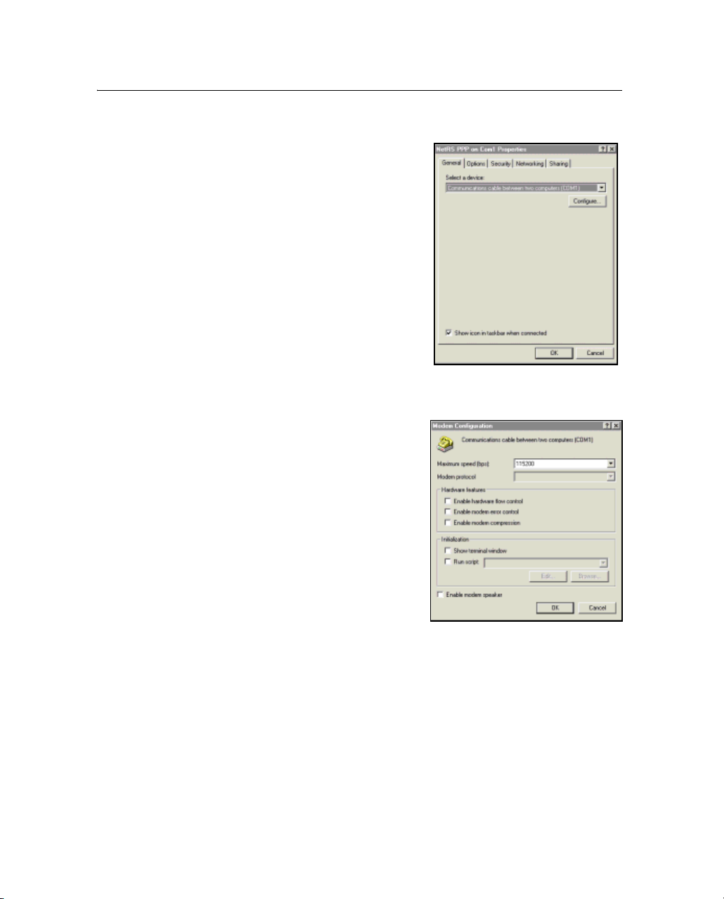
8 Other System Information
80.1 Configuring a PPP connection
1. In the Network and Dial-up
Connections dialog right-click
the connection you just
created, then select Properties
from the menu. A dialog
appears.:
2. In the General tab, click
Configure:
a. In the Maximum speed
(bps) field, select
115200.
b. Clear the Enable
hardware flow control
check box. Click
86 NetRS GPS Receiver User Guide
OK.
Page 95

3. In the Options tab, clear the
Prompt for name and
password, certificate, etc.
check box.
4. In the Security tab, select
Typical (recommended
settings).
Other System Information 8
NetRS GPS Receiver User Guide 87
Page 96

8 Other System Information
5. In the Networking tab:
a. In the Type of dial-up
b. In the Components
c. Select Internet
d. Make sure that the
server I am calling field,
make sure that PPP is
selected.
checked are used by this
connection group, clear
the check boxes for File
and Printer Sharing for
Microsoft Networks and
Client for Microsoft
Networks.
Protocol (TCP/IP) and
then click
Properties.
check boxes for Obtain
an IP address
automatically and
Obtain DNS server
address automatically
are selected.
88 NetRS GPS Receiver User Guide
Page 97

e. Click Advanced. Clear
the Use default
gateway on remote
network check box.
Make sure that the Use
IP header compression
check box is selected.
Click
OK.
Other System Information 8
6. Click
80.1 Using the PPP connection
OK in the other dialogs that appear.
Once you have successfully configured the connection, the
Connecting dialog appears to show that the system is dialing,
verifying your username and password, and authenticating the
connection. Once the system is connected, the dialog disappears and
the dial-up networking icon appears in the system tray.
To view the current connection status, double-click the icon. In the
dialog that appears, click the Details tab to view the Server (NetRS
receiver) and Client (computer) IP addresses. With the Server IP
address, you can access the receiver, using standard network tools like
Ping, SSH, and the Web browser. For example, if the Server IP address
is 192.168.143.1, start the Web browser, then enter
URL field.
80.2 Closing the PPP session
1. Double-click the dial-up networking icon.
2. Click
Disconnect.
192.168.143.1 in the
NetRS GPS Receiver User Guide 89
Page 98

8 Other System Information
80.1 Re-connecting the PPP session
1. Click Start / Settings / Network and Dial-up Connections.
2. Select the connection that you previously created in Creating a
PPP connection, page 85.
Note – The Password dialog does not appear.
The Connecting dialog appears, then closes when the
connection is established.
80.1 Editing PPP connection properties
1. Select Start / Settings / Control Panel.
2. To edit the network connection properties:
a. Double-click Network and Dial-up Connections.
b. Right-click the connection to edit and then select
Properties.
3. To edit the COM port settings, do one of the following:
–Open the Properties dialog (see the previous step). Then
click
Configure in the General tab.
– Double-click Phone and Modem Options. In the Modems
tab, select the connection created in Step 4 on page 85.
Properties.
Click
80.1 Deleting a PPP connection
1. Select Start / Settings / Control Panel.
2. To delete a network connection:
a. Double-click Networking and Dial-up Connections.
b. Right-click the connection to delete, then select Delete.
This does not automatically delete the modem entry
created for this connection.
90 NetRS GPS Receiver User Guide
Page 99

Other System Information 8
3. To delete the modem entry:
a. Double-click Phone and Modem Options.
b. In the Modems tab, select the entry to delete, then click
Remove.
NetRS GPS Receiver User Guide 91
Page 100

8 Other System Information
92 NetRS GPS Receiver User Guide
 Loading...