

Page 1

Page 2

Page 3

Version A 1.2.0
Part Number C216E
June 2008
F
USER GUIDE
Trimble® M3 Total Station
Page 4

Contact Information
Trimble Navigation Limited
Engineering and Construction Division
5475 Kellenburger Road
Dayton, Ohio 45424-1099
USA
800-538-7800 (toll free in USA)
+1-937-245-5600 Phone
+1-937-233-9004 Fax
www.trimble.com
Copyright and Trademarks
© 2007-2008, Nikon-Trimble Co. Limited. All rights reserved. Trimble, the
Globe and Triangle logo, Elta, and Terramodel are trademarks of Trimble
Navigation Limited, registered in the United States Patent and Trademark
Office and in other countries. TRIMMARK, and TRIMTALK are trademarks of
Trimble Navigation Limited. Microsoft and Windows are either registered
trademarks or trademarks of Microsoft Corporation in the United States
and/or other countries. All other trademarks are the property of their
respective owners.
It is prohibited to alter this manual in part or whole without express
permission.
The contents of this manual are subject to change without notice. Although
every effort has been made to ensure the accuracy of this manual, please
contact your dealer if you find anything in it that is incorrect or unclear.
Release Notice
This is the June 2008 release of the
Trimble M3 Total Station User Guide
,
part number C216E. It applies to version 1.2x of the Trimble M3 total
station.
Manufacturer
Nikon-Trimble Co., Ltd.
Technoport Mituiseimei Bldg.
16-2, Minamikamata 2-chome, Ota-ku
Tokyo 144-0035 Japan
Notices
USA
FCC 15B Class B satisfied.
This equipment has been tested and found to comply with the limits for a
Class B personal computer and peripherals, pursuant to Part 15 of the FCC
Rules. These limits are designed to provide reasonable protection against
harmful interference in a residential installation. This equipment generates,
uses and can radiate radio frequency energy and, if not installed and used
in accordance with the instructions, may cause harmful interference to radio
communications. However, there is no guarantee that interference will not
occur in a particular installation.
If this equipment does cause harmful interference to radio or television
reception, which can be determined by turning the equipment off and on,
the user is encouraged to try to correct the interference by one or more of
the following measures:
– Reorient or relocate the receiving antenna.
– Increase the separation between the equipment and receiver.
– Connect the equipment into an outlet on a circuit different from that to
which the receiver is connected.
– Consult the dealer or an experienced radio/TV technician for help.
C
WARNING - This equipment has been certified to comply with
the limits for a Class B personal computer and peripherals,
pursuant to Subpart B of Part 15 of FCC Rules. Only peripherals
(computer input/output devices, terminals, printers, etc.) certified
to comply with the Class B limits may be attached to this
equipment. Operation with non-certified personal computer
and/or peripherals is likely to result in interference to radio and TV
reception. The connection of a non-shielded equipment interface
cable to this equipment will invalidate the FCC Certification of
this device and may cause interference levels which exceed the
limits established by the FCC for this equipment.
You are cautioned that changes or modifications not expressly
approved by the party responsible for compliance could void your
authority to operate the equipment.
European Union
EU EMC Directive satisfied.
Authorized Representative in Europe
Trimble GmbH
Am Prime Parc 11
65479 Raunheim, Germany
Canada
This Class B digital apparatus meets all requirements of the Canadian
Interference-Causing Equipment Regulations.
Cet appareil numérique de la Class B respecte toutes les exigences du
Règlement sur le matériel brouilleur du Canada.
Recycling
Taiwan Battery Recycling Requirements
The product contains a removable battery. Taiwanese
regulations require that waste batteries are recycled.
Notice to Our European Union Customers
For product recycling instructions and more information, please go to:
www.trimble.com/environment/summary.html
Recycling in Europe
To recycle Trimble WEEE, call: +31 497 53 2430, and
ask for the WEEE associate, or mail a request for recycling
instructions to:
Trimble Europe BV
c/o Menlo Worldwide Logistics
Meerheide 45
5521 DZ Eersel, NL
Page 5

Trimble M3 Total Station User Guide iii
Safety and Warnings
For your safety read the safety and warnings and this user guide carefully and
thoroughly before using the Trimble
®
M3 total station.
Although Trimble products are designed for maximum safety, using them incorrectly
or disregarding the instructions can cause personal injury or property damage.
You should also read the instruction manual for the battery charger, and the
documentation for any other equipment that you use with a Trimble M3 total station.
Note – Always keep the manual near the instrument for easy reference.
.1 Warnings and Cautions
The following conventions are used to indicate safety instructions:
C
WARNING – Warnings alert you to situations that could cause death or serious injury.
C
CAUTION – Cautions alert you to situations that could cause injury or property damage.
Always read and follow the instructions carefully.
1.1 Warnings
Before using the instrument, read the following warnings and follow the instructions
that they provide:
C
WARNING – Never look at the sun through the telescope. If you do, you may damage or
lose your eyesight.
C
WARNING – The Trimble M3 total station is not designed to be explosion-proof. Do not
use the instrument in coal mines, in areas contaminated with coal dust, or near other
flammable substances.
C
WARNING – Never disassemble, modify, or repair the instrument yourself. If you do, you
may receive electric shocks or burns, or the instrument may catch fire.
C
WARNING – Use only the battery charger that is attached to the instrument. Do not use
any other charger or you may cause the battery pack to catch fire or rupture. The enclosed
battery pack (BC-65) cannot be used with other chargers, such as a charger with part
number Q-7U/E or Q-7C.
Page 6

Safety and Warnings
iv Trimble M3 Total Station User Guide
C
WARNING – Do not cover the battery charger while the battery pack is being recharged.
The charger must be able to dissipate heat adequately. Coverings such as blankets or
clothing can cause the charger to overheat.
C
WARNING – Avoid recharging the battery pack in humid or dusty places, in direct
sunlight, or near heat sources. Do not recharge the battery pack when it is wet. If you do,
you may receive electric shocks or burns, or the battery pack may overheat or catch fire.
C
WARNING – Although the battery pack (part number BC-65) has an auto-reset circuit
breaker, you should take care not to short circuit the contacts. Short circuits can cause the
battery pack to catch fire or burn you.
C
WARNING – Never burn or heat the battery. Doing so may cause the battery to leak or
rupture. A leaking or ruptured battery can cause serious injury.
C
WARNING – Before storing the battery pack or battery charger, cover the contact points
with insulation tape. If you do not cover the contact points, the battery pack or charger
may short circuit, causing fire, burns, or damage to the instrument.
C
WARNING – The battery BC-65 is not waterproof on its own. Do not get the battery wet
when it is removed from the instrument. If water seeps into the battery, it may cause a
fire or burns.
1.2 Cautions
Before using the instrument, read the following cautions and follow the instructions
that they provide:
C
CAUTION – Use of controls, adjustments, or performance of procedures other than those
specified herein may result in hazardous radiation exposure.
C
CAUTION – The tops of the tripod ferrules are very sharp. When handling or carrying the
tripod, take care to avoid injuring yourself on the ferrules.
C
CAUTION – Before carrying the tripod or the instrument in the carrying case, check the
shoulder strap and its clasp. If the strap is damaged or the clasp is not securely fastened,
the carrying case may fall, causing personal injury or instrument damage.
Page 7

Trimble M3 Total Station User Guide v
Safety and Warnings
C
CAUTION – Before setting up the tripod, make sure that no-one’s hands or feet are
underneath it. When the legs of the tripod are being driven into the ground, they could
pierce hands or feet.
C
CAUTION – After mounting the instrument on the tripod, securely fasten the thumb
screws on the tripod legs. If the thumb screws are not securely fastened, the tripod may
collapse, causing personal injury or instrument damage.
C
CAUTION – After mounting the instrument on the tripod, securely fasten the clamp screw
on the tripod. If the clamp screw is not securely fastened, the instrument may fall off the
tripod, causing personal injury or instrument damage.
C
CAUTION – Securely fasten the tribrach clamp knob. If the knob is not securely fastened,
the tribrach may come loose or fall off when you lift the instrument, causing personal
injury or instrument damage.
C
CAUTION – Do not stack objects on the plastic carrying case, or use it as a stool. The
plastic carrying case is unstable and its surface is slippery. Stacking or sitting on the plastic
carrying case may cause personal injury or instrument damage.
C
CAUTION – Make sure the laser is disabled before disposing of the instrument.
C
CAUTION – The system in the instrument may stop functioning in order to avoid any
errors in measurement when the instrument detects strong electromagnetic wave(s). If
this is the case, turn off the instrument and remove the source of the electromagnetic
wave(s). Then turn on the instrument to resume the work.
.2 Laser safety
The Trimble M3 3” and 5” DR total stations are a Class 3R laser instrument.
Trimble M3 total station is a Class 3R Laser Product in accordance with: IEC60825-1,
Am2 (2001): “Safety of Laser Products”
Use of the Laser Class 3R equipment can be dangerous.
Precautions: To counteract hazards, it is essential for all users to pay careful attention
to the safety precautions and control measures specified in the standard IEC60825-1
(2001-08) resp. EN60825-1:1994 + A11:1996 + A2:2001, within the hazard distance *);
particularly on to “User’s Guide”.
Page 8

Safety and Warnings
vi Trimble M3 Total Station User Guide
C
WARNING – Only qualified and trained persons should be assigned to install, adjust and
operate the laser equipment.
C
WARNING – Areas in which these lasers are used should be posted with an appropriate
laser warning sign.
C
WARNING – Precautions should be taken to ensure that persons do not look directly, with
or without an optical instrument, into the beam.
C
WARNING – The laser beam should be terminated at the end of its useful beam path and
should in all cases be terminated if the hazardous beam path extends beyond the limit
(hazard distance *) of the area in which the presence and activities of personnel are
monitored for reasons of protection from laser radiation.
C
WARNING – Laser beam path should be located well above or below eye level wherever
practicable.
C
WARNING – When the laser product is not used, it should be stored in a location where
unauthorized personnel cannot gain access.
C
WARNING – Do NOT turn the class 3R laser beam to mirror like specular surfaces; for
instance, prisms, metal surfaces or windows, even unintentionally. Special precautions
should be taken to ensure eliminating such situations.
*The hazard distance is the distance from the laser at which beam irradiance or
radiant exposure equals the maximum permissible value to which personnel may
be exposed without being exposed to health risk.
Page 9

Trimble M3 Total Station User Guide vii
Safety and Warnings
2.1 Specifications for laser emission
2.2 Conforming standards
Wave length 630-680 nm
Laser pointer CW Po ≤ 4.75 mW
Measurement in
Reflectorless mode
Pulse
Pp ≤ 8.75 mW Po ≤ 4.75 mW
1.2 nsec/400 MHz - 1.6 nsec/320 MHz
EU
EN60825-1/Am.2:2001 (IEC60825-1/Am.2:2001), class 3R
USA
FDA21CFR Part 1040 Sec.1040.10 and 1040.11
Except for deviations pursuant to Laser Notice No.50, dated June
24, 2007
Page 10

Safety and Warnings
viii Trimble M3 Total Station User Guide
Page 11

Trimble M3 Total Station User Guide 1
Contents
Safety and Warnings. . . . . . . . . . . . . . . . . . . . . . . . . . . . . . . iii
Warnings and Cautions . . . . . . . . . . . . . . . . . . . . . . . . . . . . . . . . . . . . . . . . . . . . . . iii
Warnings . . . . . . . . . . . . . . . . . . . . . . . . . . . . . . . . . . . . . . . . . . . . . . . . . . .iii
Cautions . . . . . . . . . . . . . . . . . . . . . . . . . . . . . . . . . . . . . . . . . . . . . . . . . . . iv
Laser safety . . . . . . . . . . . . . . . . . . . . . . . . . . . . . . . . . . . . . . . . . . . . . . . . . . . . . . v
Specifications for laser emission . . . . . . . . . . . . . . . . . . . . . . . . . . . . . . . . . . . vii
Conforming standards . . . . . . . . . . . . . . . . . . . . . . . . . . . . . . . . . . . . . . . . . vii
1 Introduction . . . . . . . . . . . . . . . . . . . . . . . . . . . . . . . . . . . . 7
Welcome . . . . . . . . . . . . . . . . . . . . . . . . . . . . . . . . . . . . . . . . . . . . . . . . . . . . . . . 8
About the Trimble Trimble M3 total station . . . . . . . . . . . . . . . . . . . . . . . . . . . . . . . . . 8
System diagram . . . . . . . . . . . . . . . . . . . . . . . . . . . . . . . . . . . . . . . . . . . . . . . . . . . 9
Related information . . . . . . . . . . . . . . . . . . . . . . . . . . . . . . . . . . . . . . . . . . . . . . . . 9
Technical assistance . . . . . . . . . . . . . . . . . . . . . . . . . . . . . . . . . . . . . . . . . . . . . . . 10
Your comments . . . . . . . . . . . . . . . . . . . . . . . . . . . . . . . . . . . . . . . . . . . . . . . . . . 10
2 Overview of the Trimble M3 Total Station . . . . . . . . . . . . . . . . . . 11
Hardware overview . . . . . . . . . . . . . . . . . . . . . . . . . . . . . . . . . . . . . . . . . . . . . . . . 12
Maintenance . . . . . . . . . . . . . . . . . . . . . . . . . . . . . . . . . . . . . . . . . . . . . . . . . . . . 14
LCD display and key functions. . . . . . . . . . . . . . . . . . . . . . . . . . . . . . . . . . . . . . . . . 15
Key functions . . . . . . . . . . . . . . . . . . . . . . . . . . . . . . . . . . . . . . . . . . . . . . . 16
Adjusting lighting, laser, sound, and contrast . . . . . . . . . . . . . . . . . . . . . . . . . . . 17
Status bar. . . . . . . . . . . . . . . . . . . . . . . . . . . . . . . . . . . . . . . . . . . . . . . . . . 18
Software overview. . . . . . . . . . . . . . . . . . . . . . . . . . . . . . . . . . . . . . . . . . . . . . . . . 20
MENU overview . . . . . . . . . . . . . . . . . . . . . . . . . . . . . . . . . . . . . . . . . . . . . 20
HOT MENU overview . . . . . . . . . . . . . . . . . . . . . . . . . . . . . . . . . . . . . . . . . . 22
Principles of display . . . . . . . . . . . . . . . . . . . . . . . . . . . . . . . . . . . . . . . . . . . . . . . 22
Basic Measurement Screen (BMS) . . . . . . . . . . . . . . . . . . . . . . . . . . . . . . . . . . 23
Input screen . . . . . . . . . . . . . . . . . . . . . . . . . . . . . . . . . . . . . . . . . . . . . . . . 23
Menu screen . . . . . . . . . . . . . . . . . . . . . . . . . . . . . . . . . . . . . . . . . . . . . . . . 24
Inputting data . . . . . . . . . . . . . . . . . . . . . . . . . . . . . . . . . . . . . . . . . . . . . . . . . . . 24
Changing between alphanumeric and numeric input . . . . . . . . . . . . . . . . . . . . . . 24
Stack. . . . . . . . . . . . . . . . . . . . . . . . . . . . . . . . . . . . . . . . . . . . . . . . . . . . . 25
List . . . . . . . . . . . . . . . . . . . . . . . . . . . . . . . . . . . . . . . . . . . . . . . . . . . . . . 25
3 Before Going to the Field . . . . . . . . . . . . . . . . . . . . . . . . . . . . 27
Unpacking and packing the instrument. . . . . . . . . . . . . . . . . . . . . . . . . . . . . . . . . . . 28
Unpacking the instrument . . . . . . . . . . . . . . . . . . . . . . . . . . . . . . . . . . . . . . . 28
Packing the instrument . . . . . . . . . . . . . . . . . . . . . . . . . . . . . . . . . . . . . . . . . 28
Charging and discharging the battery pack . . . . . . . . . . . . . . . . . . . . . . . . . . . . . . . . . 28
Safety notices . . . . . . . . . . . . . . . . . . . . . . . . . . . . . . . . . . . . . . . . . . . . . . . 28
Charging the battery pack . . . . . . . . . . . . . . . . . . . . . . . . . . . . . . . . . . . . . . . 30
Detaching the BC-65 battery pack from the instrument . . . . . . . . . . . . . . . . . . . . 31
Page 12

Contents
2 Trimble M3 Total Station User Guide
Attaching the BC-65 battery pack to the instrument . . . . . . . . . . . . . . . . . . . . . . 31
Selecting a language . . . . . . . . . . . . . . . . . . . . . . . . . . . . . . . . . . . . . . . . . . . . . . . 32
Changing regional configuration presets . . . . . . . . . . . . . . . . . . . . . . . . . . . . . . . . . . 32
Instrument settings. . . . . . . . . . . . . . . . . . . . . . . . . . . . . . . . . . . . . . . . . . . . . . . . 34
Basic measurement settings . . . . . . . . . . . . . . . . . . . . . . . . . . . . . . . . . . . . . . 34
Configuring data recording and external communication settings. . . . . . . . . . . . . . 38
Frequently used settings (HOT MENU settings) . . . . . . . . . . . . . . . . . . . . . . . . . 39
4 Getting Started in the Field. . . . . . . . . . . . . . . . . . . . . . . . . . . 47
Setting up the tripod . . . . . . . . . . . . . . . . . . . . . . . . . . . . . . . . . . . . . . . . . . . . . . . 48
Centering . . . . . . . . . . . . . . . . . . . . . . . . . . . . . . . . . . . . . . . . . . . . . . . . . . . . . . 48
Centering with optical plummet . . . . . . . . . . . . . . . . . . . . . . . . . . . . . . . . . . . 48
Leveling . . . . . . . . . . . . . . . . . . . . . . . . . . . . . . . . . . . . . . . . . . . . . . . . . . . . . . . 49
Focusing the telescope. . . . . . . . . . . . . . . . . . . . . . . . . . . . . . . . . . . . . . . . . . . . . . 50
Setting the measurement mode and preparing the target . . . . . . . . . . . . . . . . . . . . . . . 51
Measurement with a prism. . . . . . . . . . . . . . . . . . . . . . . . . . . . . . . . . . . . . . . 51
Measurement in Direct-Reflex mode . . . . . . . . . . . . . . . . . . . . . . . . . . . . . . . . 52
Turning the instrument on and off . . . . . . . . . . . . . . . . . . . . . . . . . . . . . . . . . . . . . . 53
Turning on the instrument. . . . . . . . . . . . . . . . . . . . . . . . . . . . . . . . . . . . . . . 53
Turning off the instrument. . . . . . . . . . . . . . . . . . . . . . . . . . . . . . . . . . . . . . . 53
Sleep mode . . . . . . . . . . . . . . . . . . . . . . . . . . . . . . . . . . . . . . . . . . . . . . . . . 54
5 Basic Measurement Screen . . . . . . . . . . . . . . . . . . . . . . . . . . . 55
Measurement mode . . . . . . . . . . . . . . . . . . . . . . . . . . . . . . . . . . . . . . . . . . . . . . . 56
Changing the screen display . . . . . . . . . . . . . . . . . . . . . . . . . . . . . . . . . . . . . . . . . . 57
Changing the distance unit . . . . . . . . . . . . . . . . . . . . . . . . . . . . . . . . . . . . . . . . . . . 58
Taking measurements . . . . . . . . . . . . . . . . . . . . . . . . . . . . . . . . . . . . . . . . . . . . . . 59
Tracking mode . . . . . . . . . . . . . . . . . . . . . . . . . . . . . . . . . . . . . . . . . . . . . . 59
Setting the horizontal angle (HA) . . . . . . . . . . . . . . . . . . . . . . . . . . . . . . . . . . . . . . . 60
Setting target height (th) and instrument height (ih). . . . . . . . . . . . . . . . . . . . . . . . . . . 60
Setting the station elevation . . . . . . . . . . . . . . . . . . . . . . . . . . . . . . . . . . . . . . . . . . 61
Instrument height (ih) and station-Z coordinate (Zs) . . . . . . . . . . . . . . . . . . . . . . 62
Measuring edges and corners using the Intersection program (INTS) . . . . . . . . . . . . . . . . 63
Bearing-Distance . . . . . . . . . . . . . . . . . . . . . . . . . . . . . . . . . . . . . . . . . . . . . 63
Corner-Angle . . . . . . . . . . . . . . . . . . . . . . . . . . . . . . . . . . . . . . . . . . . . . . . 64
Intersection . . . . . . . . . . . . . . . . . . . . . . . . . . . . . . . . . . . . . . . . . . . . . . . . 65
Eccentric Object . . . . . . . . . . . . . . . . . . . . . . . . . . . . . . . . . . . . . . . . . . . . . 66
6 Job Manager . . . . . . . . . . . . . . . . . . . . . . . . . . . . . . . . . . . 67
Creating a new job . . . . . . . . . . . . . . . . . . . . . . . . . . . . . . . . . . . . . . . . . . . . . . . . 68
Opening an existing job . . . . . . . . . . . . . . . . . . . . . . . . . . . . . . . . . . . . . . . . . . . . . 70
Deleting a job . . . . . . . . . . . . . . . . . . . . . . . . . . . . . . . . . . . . . . . . . . . . . . . . . . . 70
Setting the Control Point job . . . . . . . . . . . . . . . . . . . . . . . . . . . . . . . . . . . . . . . . . . 71
Displaying job information . . . . . . . . . . . . . . . . . . . . . . . . . . . . . . . . . . . . . . . . . . . 72
Editing data . . . . . . . . . . . . . . . . . . . . . . . . . . . . . . . . . . . . . . . . . . . . . . . . . . . . 72
Page 13

Trimble M3 Total Station User Guide 3
Contents
7 Coordinates. . . . . . . . . . . . . . . . . . . . . . . . . . . . . . . . . . . . 73
Resection . . . . . . . . . . . . . . . . . . . . . . . . . . . . . . . . . . . . . . . . . . . . . . . . . . . . . . 74
Known Station . . . . . . . . . . . . . . . . . . . . . . . . . . . . . . . . . . . . . . . . . . . . . . . . . . . 79
Orientation using a known azimuth . . . . . . . . . . . . . . . . . . . . . . . . . . . . . . . . . 80
Orientation using known coordinates . . . . . . . . . . . . . . . . . . . . . . . . . . . . . . . . 81
Station elevation . . . . . . . . . . . . . . . . . . . . . . . . . . . . . . . . . . . . . . . . . . . . . . . . . 83
Measure topo. . . . . . . . . . . . . . . . . . . . . . . . . . . . . . . . . . . . . . . . . . . . . . . . . . . . 83
Confirming the station coordinates . . . . . . . . . . . . . . . . . . . . . . . . . . . . . . . . . 83
Confirming the backsight point angle . . . . . . . . . . . . . . . . . . . . . . . . . . . . . . . . 83
Confirming the instrument height and Station-Z coordinates . . . . . . . . . . . . . . . . 84
Sighting new points in the Topo observation screen. . . . . . . . . . . . . . . . . . . . . . . 84
Stakeout . . . . . . . . . . . . . . . . . . . . . . . . . . . . . . . . . . . . . . . . . . . . . . . . . . . . . . . 86
Stake out by coordinates (XY or XYZ) . . . . . . . . . . . . . . . . . . . . . . . . . . . . . . . . 87
Stakeout by angle and distance (HD or HDh) . . . . . . . . . . . . . . . . . . . . . . . . . . . 89
Stakeout by reference line . . . . . . . . . . . . . . . . . . . . . . . . . . . . . . . . . . . . . . . 90
Stakeout by dividing line . . . . . . . . . . . . . . . . . . . . . . . . . . . . . . . . . . . . . . . . 91
8 Applications . . . . . . . . . . . . . . . . . . . . . . . . . . . . . . . . . . . 95
Connecting distance . . . . . . . . . . . . . . . . . . . . . . . . . . . . . . . . . . . . . . . . . . . . . . . 96
Choosing 2D or 3D observation. . . . . . . . . . . . . . . . . . . . . . . . . . . . . . . . . . . . 96
Start connecting distances. . . . . . . . . . . . . . . . . . . . . . . . . . . . . . . . . . . . . . . 97
Remote object height . . . . . . . . . . . . . . . . . . . . . . . . . . . . . . . . . . . . . . . . . . . . . .100
Recording data from connecting distance . . . . . . . . . . . . . . . . . . . . . . . . . . . . .101
Station and offset . . . . . . . . . . . . . . . . . . . . . . . . . . . . . . . . . . . . . . . . . . . . . . . . . 102
Shifting the coordinate axes y, x. . . . . . . . . . . . . . . . . . . . . . . . . . . . . . . . . . . . 104
Vertical plane. . . . . . . . . . . . . . . . . . . . . . . . . . . . . . . . . . . . . . . . . . . . . . . . . . . .105
Compute area . . . . . . . . . . . . . . . . . . . . . . . . . . . . . . . . . . . . . . . . . . . . . . . . . . .107
9 Data Transfer . . . . . . . . . . . . . . . . . . . . . . . . . . . . . . . . . . 109
Hardware interface . . . . . . . . . . . . . . . . . . . . . . . . . . . . . . . . . . . . . . . . . . . . . . . .110
Specifications . . . . . . . . . . . . . . . . . . . . . . . . . . . . . . . . . . . . . . . . . . . . . . . . . . .111
XON/XOFF Control . . . . . . . . . . . . . . . . . . . . . . . . . . . . . . . . . . . . . . . . . . . . . . . 111
Downloading internal memory to an office computer . . . . . . . . . . . . . . . . . . . . . . . . . . 111
Transferring recorded data to the office computer . . . . . . . . . . . . . . . . . . . . . . . . . . . . 112
Uploading data from an office computer to the internal memory . . . . . . . . . . . . . . . . . .113
Nikon data fields . . . . . . . . . . . . . . . . . . . . . . . . . . . . . . . . . . . . . . . . . . . . . 113
Uploading a point name/number list from the office computer. . . . . . . . . . . . . . . . . . . . 114
Uploading a point code list from the office computer . . . . . . . . . . . . . . . . . . . . . . . . . .114
10 Checking and Adjustment. . . . . . . . . . . . . . . . . . . . . . . . . . . 115
Checking and adjusting the plate level. . . . . . . . . . . . . . . . . . . . . . . . . . . . . . . . . . . . 116
Checking and adjusting the circular level . . . . . . . . . . . . . . . . . . . . . . . . . . . . . . . . . .116
Checking and adjusting the optical plummet . . . . . . . . . . . . . . . . . . . . . . . . . . . . . . .117
Checking the instrument constant . . . . . . . . . . . . . . . . . . . . . . . . . . . . . . . . . . . . . .118
Checking and adjusting the compensator (C) and index (I) . . . . . . . . . . . . . . . . . . . . . .119
Page 14

Contents
4 Trimble M3 Total Station User Guide
Vertical index and HA collimation . . . . . . . . . . . . . . . . . . . . . . . . . . . . . . . . . .119
Compensator adjustment . . . . . . . . . . . . . . . . . . . . . . . . . . . . . . . . . . . . . . . 120
Checking and adjusting the laser pointer . . . . . . . . . . . . . . . . . . . . . . . . . . . . . . . . . .121
Aligning the laser pointer. . . . . . . . . . . . . . . . . . . . . . . . . . . . . . . . . . . . . . . .121
Adjusting the laser beam . . . . . . . . . . . . . . . . . . . . . . . . . . . . . . . . . . . . . . . .122
A Troubleshooting . . . . . . . . . . . . . . . . . . . . . . . . . . . . . . . . 125
Points . . . . . . . . . . . . . . . . . . . . . . . . . . . . . . . . . . . . . . . . . . . . . . . . . . . . . . . .126
Settings interface . . . . . . . . . . . . . . . . . . . . . . . . . . . . . . . . . . . . . . . . . . . . . . . . .126
Job Manager . . . . . . . . . . . . . . . . . . . . . . . . . . . . . . . . . . . . . . . . . . . . . . . . . . . .126
Stakeout . . . . . . . . . . . . . . . . . . . . . . . . . . . . . . . . . . . . . . . . . . . . . . . . . . . . . . .127
Uploading Point Name / Point Code list. . . . . . . . . . . . . . . . . . . . . . . . . . . . . . . . . . .127
Adjustment C&I . . . . . . . . . . . . . . . . . . . . . . . . . . . . . . . . . . . . . . . . . . . . . . . . . .128
Application . . . . . . . . . . . . . . . . . . . . . . . . . . . . . . . . . . . . . . . . . . . . . . . . . . . . .128
B Data Formats . . . . . . . . . . . . . . . . . . . . . . . . . . . . . . . . . . 129
M5 data format . . . . . . . . . . . . . . . . . . . . . . . . . . . . . . . . . . . . . . . . . . . . . . . . . .130
The M5 data line . . . . . . . . . . . . . . . . . . . . . . . . . . . . . . . . . . . . . . . . . . . . . 130
Additional data lines of M5 data format – header/changed setting . . . . . . . . . . . . .133
Marking in the M5 format . . . . . . . . . . . . . . . . . . . . . . . . . . . . . . . . . . . . . . .136
Value blocks . . . . . . . . . . . . . . . . . . . . . . . . . . . . . . . . . . . . . . . . . . . . . . . .137
Recording data lines . . . . . . . . . . . . . . . . . . . . . . . . . . . . . . . . . . . . . . . . . . .138
Nikon data format . . . . . . . . . . . . . . . . . . . . . . . . . . . . . . . . . . . . . . . . . . . . . . . .142
Uploading coordinate data format . . . . . . . . . . . . . . . . . . . . . . . . . . . . . . . . . . 142
Downloading Nikon raw format . . . . . . . . . . . . . . . . . . . . . . . . . . . . . . . . . . .143
Point number/name list and Point code list . . . . . . . . . . . . . . . . . . . . . . . . . . . . . . . .145
File format . . . . . . . . . . . . . . . . . . . . . . . . . . . . . . . . . . . . . . . . . . . . . . . . .145
Data example . . . . . . . . . . . . . . . . . . . . . . . . . . . . . . . . . . . . . . . . . . . . . . .146
C Specifications. . . . . . . . . . . . . . . . . . . . . . . . . . . . . . . . . . 147
Telescope . . . . . . . . . . . . . . . . . . . . . . . . . . . . . . . . . . . . . . . . . . . . . . . . . . . . . .148
Measurement range . . . . . . . . . . . . . . . . . . . . . . . . . . . . . . . . . . . . . . . . . . . . . . . 148
Distance measurement precision . . . . . . . . . . . . . . . . . . . . . . . . . . . . . . . . . . . . . . .148
Measurement intervals . . . . . . . . . . . . . . . . . . . . . . . . . . . . . . . . . . . . . . . . . . . . . 149
Angle measurement . . . . . . . . . . . . . . . . . . . . . . . . . . . . . . . . . . . . . . . . . . . . . . .149
Dual-axis tilt sensor . . . . . . . . . . . . . . . . . . . . . . . . . . . . . . . . . . . . . . . . . . . . . . .149
Clamps/tangent screws . . . . . . . . . . . . . . . . . . . . . . . . . . . . . . . . . . . . . . . . . . . . . 149
Tribrach . . . . . . . . . . . . . . . . . . . . . . . . . . . . . . . . . . . . . . . . . . . . . . . . . . . . . . .150
Level vial sensitivity . . . . . . . . . . . . . . . . . . . . . . . . . . . . . . . . . . . . . . . . . . . . . . .150
Optical plummet . . . . . . . . . . . . . . . . . . . . . . . . . . . . . . . . . . . . . . . . . . . . . . . . . 150
Display and keypad . . . . . . . . . . . . . . . . . . . . . . . . . . . . . . . . . . . . . . . . . . . . . . . .150
Connections in the base of instrument . . . . . . . . . . . . . . . . . . . . . . . . . . . . . . . . . . . 150
Battery pack BC-65 . . . . . . . . . . . . . . . . . . . . . . . . . . . . . . . . . . . . . . . . . . . . . . . .151
Environmental performance . . . . . . . . . . . . . . . . . . . . . . . . . . . . . . . . . . . . . . . . . .151
Dimensions. . . . . . . . . . . . . . . . . . . . . . . . . . . . . . . . . . . . . . . . . . . . . . . . . . . . .151
Page 15

Trimble M3 Total Station User Guide 5
Contents
Weight . . . . . . . . . . . . . . . . . . . . . . . . . . . . . . . . . . . . . . . . . . . . . . . . . . . . . . . .151
Glossary . . . . . . . . . . . . . . . . . . . . . . . . . . . . . . . . . . . . . 153
Softkey glossary . . . . . . . . . . . . . . . . . . . . . . . . . . . . . . . . . . . . . . . . . . . . . . . . . .153
Glossary of terms . . . . . . . . . . . . . . . . . . . . . . . . . . . . . . . . . . . . . . . . . . . . . . . . .155
Page 16

Contents
6 Trimble M3 Total Station User Guide
Page 17

CHAPTER
1
Trimble M3 Total Station User Guide 7
Introduction 1
In this chapter:
Q Welcome
Q About the Trimble Trimble M3 total station
Q System diagram
Q Related information
Q Technical assistance
Q Your comments
Page 18

1 Introduction
8 Trimble M3 Total Station User Guide
1.1 Welcome
Thank you for purchasing the Trimble® M3 total station.
Before you operate the instrument, read this manual carefully. In particular, pay
attention to the warnings and cautions that appear in the Safety section at the front of
the manual, see Safety and Warnings, page iii.
You should also read the maintenance section, see Maintenance, page 14.
1.2 About the Trimble Trimble M3 total station
The Trimble M3 total station is easy to use. The software for the Trimble M3 series has
been designed to make it easy for you to learn to operate one model of instrument and
apply that knowledge to the other models with little additional training.
The Trimble M3 total station offers reflectorless operation, allowing you to take
measurements to points inaccessible with a prism. This manual shows the unique
capabilities and features available in the Trimble M3 total station.
Page 19
Trimble M3 Total Station User Guide 9
Introduction 1
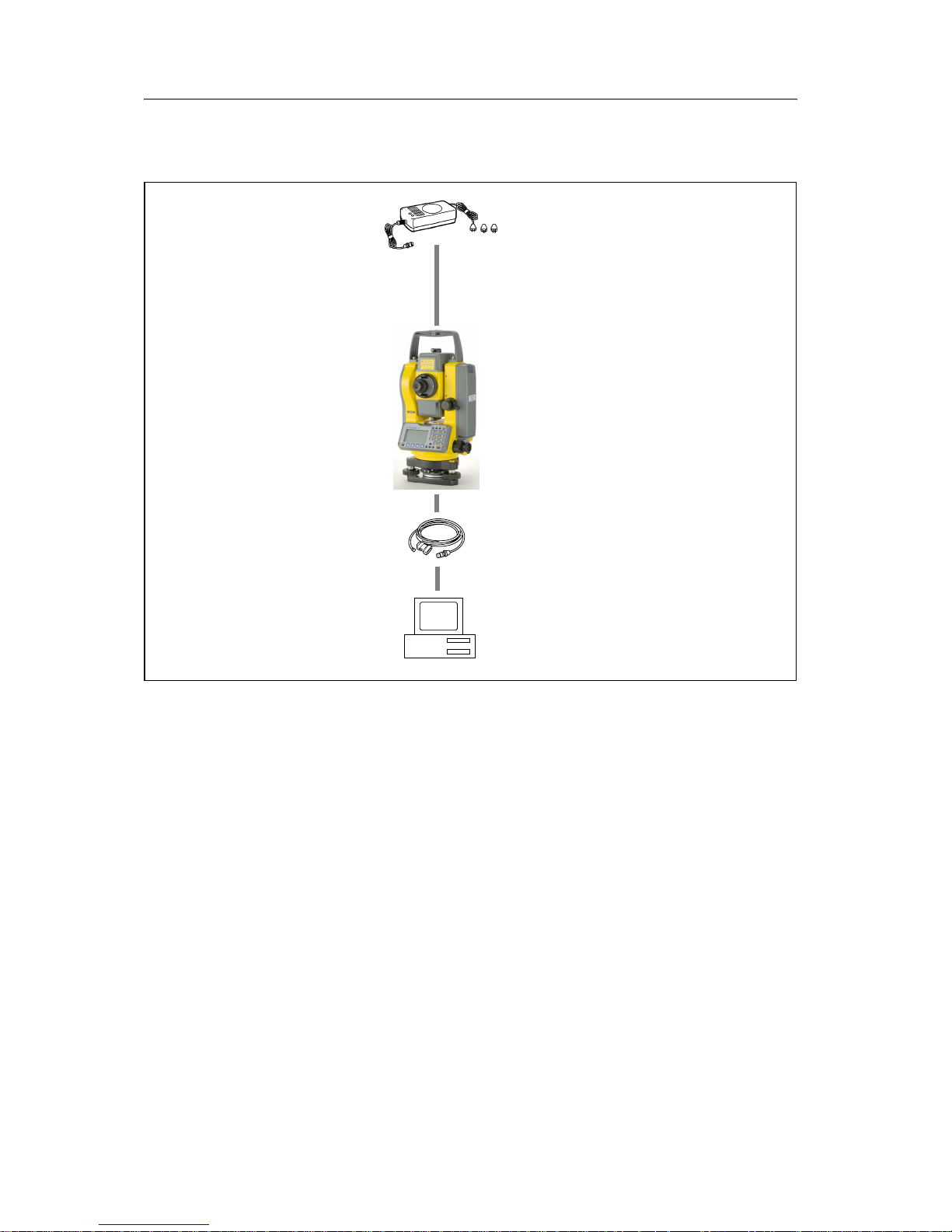
1.3 System diagram
Figure 1.1 System diagram
1.4 Related information
• Contact your local Trimble dealer for more information about the support
agreement contracts for software and firmware, and an extended warranty
program for hardware.
• Trimble training courses – Consider a training course to help you use your total
station to its fullest potential. For more information, go to the Trimble website
at www.trimble.com/training.html.
Universal charger,
power cord, and adapters
Trimble M3
total station
DTM/PC connecting
cable (9 pin/25 pin
)
Personal computer
battery type
with NiMH
BC-65M
Page 20

1 Introduction
10 Trimble M3 Total Station User Guide
1.5 Technical assistance
If you have a problem and cannot find the information you need in the product
documentation, contact your local dealer.
Technical support
If you need to contact Trimble technical support:
1. Go to the Trimble website (www.trimble.com).
2. Click the
Support button at the top of the screen. The Support A–Z list of
products appears.
3. Scroll to the bottom of the list.
4. Click the
submit an inquiry link. A form appears.
Alternatively, you can send an e-mail to trimble_support@trimble.com
1.1 Your comments
Your feedback about the supporting documentation helps us to improve it with each
revision. E-mail your comments to ReaderFeedback@trimble.com.
Page 21

CHAPTER
2
Trimble M3 Total Station User Guide 11
Overview of the Trimble M3 Total
Station
2
In this chapter:
Q Hardware overview
Q Maintenance
Q LCD display and key functions
Q Software overview
Q Principles of display
Q Inputting data
Page 22
2 Overview of the Trimble M3 Total Station
12 Trimble M3 Total Station User Guide
This chapter gives you an overview of the operation and controls of the Trimble M3
total station, as well as the programs which are a special feature.
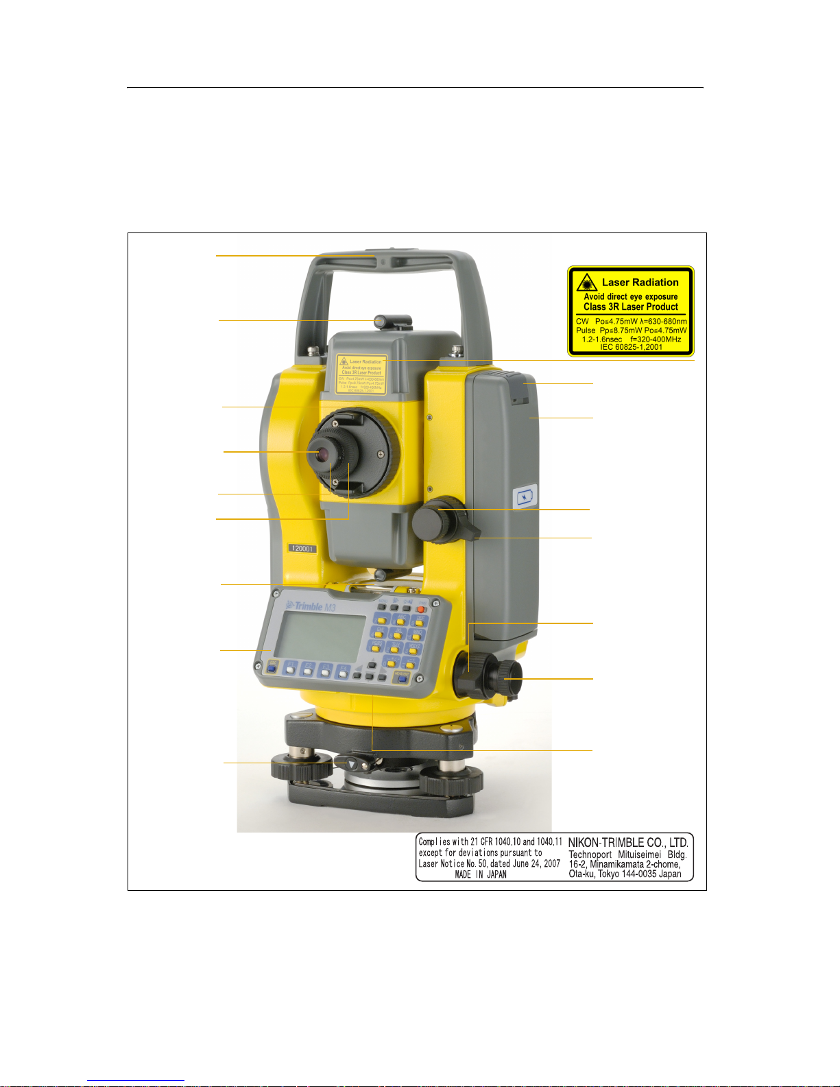
2.2 Hardware overview
Figure 2.2 and Figure 2.3 show the main parts of the Trimble M3 total station.
Figure 2.2 Trimble M3 total station – Face-1 (control side)
Carrying
handle
Optical sight
(finder)
Telescope
focusing ring
Telescope
eyepiece
Diopter ring
Rectical plate
cover
Plate level
Face-1 display
and keyboard
Tri brach
clamp knob
Battery
mounting button
Battery pack
BC-65
Vertical tangent
screw
Vertical clamp
Horizontal clamp
Horizontal
tangent screw
The laser safety
label shown is
underside of the
keyboard
attached to the
Page 23
Trimble M3 Total Station User Guide 13
Overview of the Trimble M3 Total Station 2
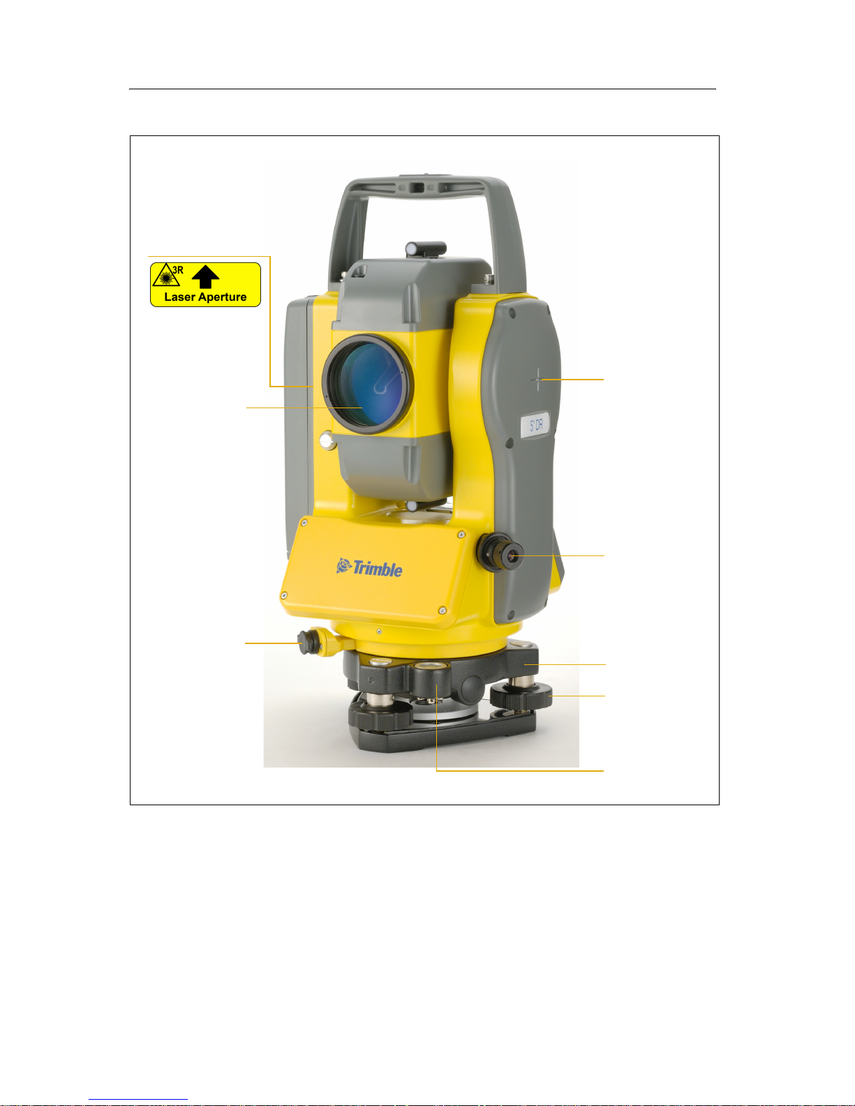
Figure 2.3 Trimble M3 total station – Face-2
Horizontal axis
indication mark
Optical plummet
Tri brach
The laser safety
label shown is
telescope
attached to the
Objective
LASER LIGHT
IS EMITTED
FROM THIS PART
Data output /
external power
input connector
WARNING
Input voltage
7.2 - 11 V DC
Leveling screw
Circular level
Page 24

2 Overview of the Trimble M3 Total Station
14 Trimble M3 Total Station User Guide
2.3 Maintenance
Before using the instrument, read and follow the following maintenance instructions:
• Do not leave the instrument in direct sunlight or in a closed vehicle for
prolonged periods. Overheating the instrument may reduce its efficiency.
• If the Trimble M3 total station has been used in wet conditions, immediately
wipe off any moisture and dry the instrument completely before returning the
instrument to the carrying case. The instrument contains sensitive electronic
assemblies which have been well protected against dust and moisture. However,
if dust or moisture gets into the instrument, severe damage could result.
• Sudden changes in temperature may cloud the lenses and drastically reduce the
measurable distance, or cause an electrical system failure. If there has been a
sudden change in temperature, leave the instrument in a closed carrying case in
a warm location until the temperature of the instrument returns to room
temperature.
• Do not store the Trimble M3 total station in hot or humid locations. In
particular, you must store the battery pack in a dry location at a temperature of
less than 30 °C (86 °F). High temperature or excessive humidity can cause mold
to grow on the lenses. It can also cause the electronic assemblies to deteriorate,
and so lead to instrument failure.
• Store the battery pack with the battery discharged.
• When storing the instrument in areas subject to extremely low temperatures,
leave the carrying case open.
• Do not overtighten any of the clamp screws.
• When adjusting the vertical tangent screws, upper plate tangent screws, or
leveling screws, stay as close as possible to the center of each screw's range. The
center is indicated by a line on the screw. For final adjustment of tangent screws,
rotate the screw clockwise.
• If the tribrach will not be used for an extended period, lock down the tribrach
clamp knob and tighten its safety screw.
• Do not use organic solvents (such as ether or paint thinner) to clean the non-
metallic parts of the instrument (such as the keyboard) or the painted or printed
surfaces. Doing so could result in discoloration of the surface, or in peeling of
printed characters. Clean these parts only with a soft cloth or a tissue, lightly
moistened with water or a mild detergent.
• To clean the optical lenses, lightly wipe them with a soft cloth or a lens tissue
that is moistened with alcohol.
Page 25
Trimble M3 Total Station User Guide 15
Overview of the Trimble M3 Total Station 2
• The reticle plate cover has been correctly mounted. Do
not release it or subject it to excessive force to make it
watertight.
• Before attaching the battery pack, check that the contact
surfaces on the battery and instrument are clean. Press
the battery pack into place until the battery mounting
button rises up to the battery pack top surface. If the
battery pack is not attached securely, the instrument is
not watertight.
• Press the cap that covers the data output/external power input connector
terminal until it clicks into place. The instrument is not watertight if the cap is
not attached securely, or when the data output/external power input connector
is used.
• The carrying case is designed to be watertight, but you should not leave it
exposed to rain for an extended period.
• The BC-65 battery pack contains a NiMH battery. When disposing of the battery
pack, follow the laws or rules of your municipal waste system. See also
Recycling, page ii.
• The instrument can be damaged by static electricity from the human body
discharged through the data output/external power input connector. Before
handling the instrument, touch any other conductive material once to remove
static electricity.
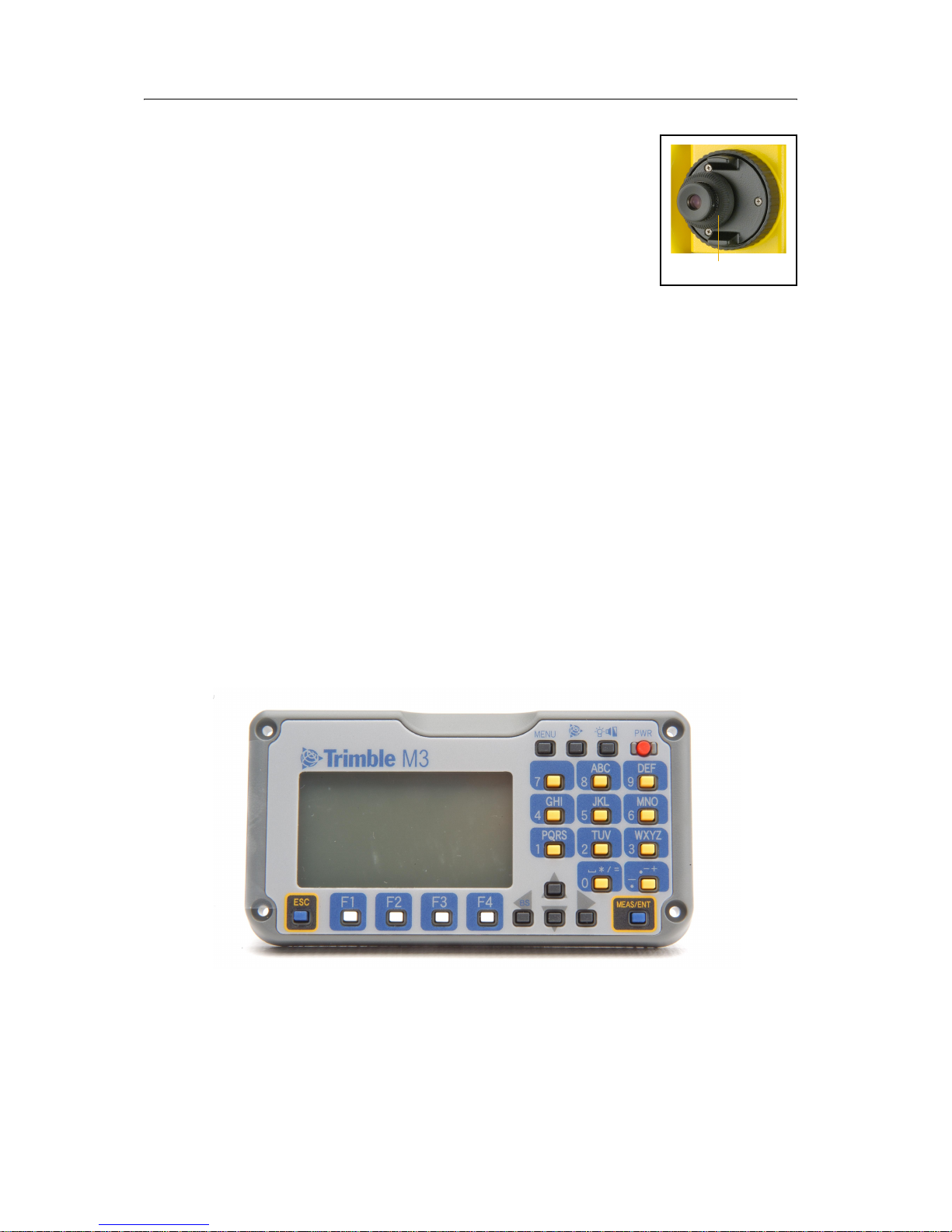
2.4 LCD display and key functions
The LCD display and keys on the Trimble M3 total station keyboard are shown below.
Reticle plate cover
Page 26
2 Overview of the Trimble M3 Total Station
16 Trimble M3 Total Station User Guide
24.1 Key functions
Ta bl e 2 .1 summarizes the functions of the Trimble M3 series keys.
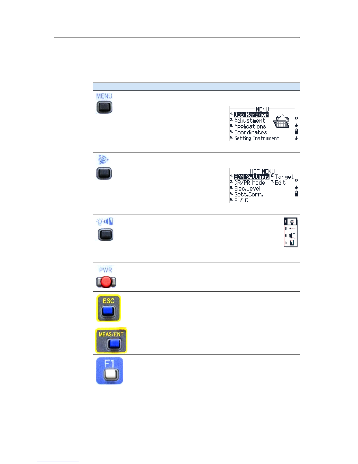
Table 2.1 Key functions
Key Function
[Menu] key. Press to display the MENU screen which contains the following
options:
1. Job Manager
2. Adjustment
3. Applications
4. Coordinates
5. Setting Instrument
6. Setting interface
7. Data Transfer
Trimble key. Press to display the
HOT MENU screen which contains the
following options:
1. EDM Settings
2. DR/PR Mode
3. Electronic Level
4. Setting Corrections
5. Point number / Point code
6. Target
7. Edit
Illumination key. Press to display the 4-switch window which
contains the following options:
1. Backlight on/off.
2. Laser pointer on/off
3. Sound on/off
4. Display contrast adjustment
See Adjusting lighting, laser, sound, and contrast, page 17.
[PWR] button. Press to turn the instrument on or off.
See Turning the instrument on and off, page 53.
[ESC] key. Press to return to the previous screen. If you are in numeric or
alpha-numeric mode press this key to delete your input.
[MEAS/ENT] key. Press to do any of the following:
• Proceed to the next step
• Initiate a measurement and record the point
• Confirm the input value/name/code when you are in input mode
[F1] - [F4] Function keys. When softkeys (for example Stack) are displayed at
the bottom of the screen, press the function key beneath the softkey
indication.
Note – The fields at the bottom of each screen relate to the function of the
keys situated below the display. They indicate the next possible setting, not
the current setting.
Page 27
Trimble M3 Total Station User Guide 17
Overview of the Trimble M3 Total Station 2
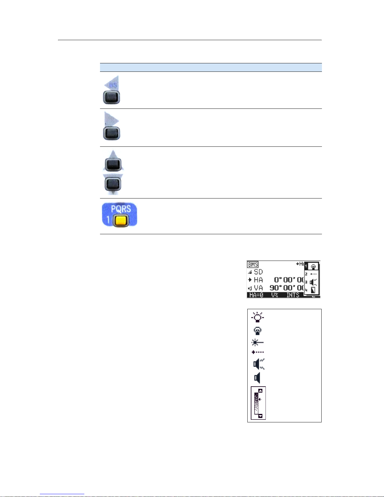
24.2 Adjusting lighting, laser, sound, and contrast
You can adjust the lighting and sound levels from any
screen:
1. Press the illumination key to display the 4-switch
window.
2. To cycle through the settings for the backlight,
sound and laser, press the number beside the
switch. For example, to turn the backlight on or
off, press
[1]. Alternatively, to highlight the switch
that you want to set, press
[^] or [v] and then press
[<] or [>] to change the setting.
3. To adjust the contrast when the 4-switch window
is open:
a. Press
[4], [<] or [>] to display the contrast
adjustment window.
b. Press
[^] or [v] to change the contrast level.
The arrow indicates the current contrast
level.
[<] Left arrow key. Move the highlighted cursor to the left, or delete a
character when you are in the input mode.
[>] Right arrow key. Move the highlighted cursor to the right.
[^] [v] Up and down arrow keys. Move the highlighted cursor up or down in list
and
MENU screens. Also used to move between the BMS screens.
The keypad is used to enter numbers and alphabetic characters.
In this example, press the key to enter
[1] when the instrument is set for
numeric input, and press the key one or more times to enter P, Q, R, or S in
capitals or lower-case characters.
Table 2.1 Key functions
Key Function
LCD backlight on
LCD backlight off
Sound on.
Sound off
Contrast
adjustment
window
Laser pointer off
Laser pointer on
Page 28
2 Overview of the Trimble M3 Total Station
18 Trimble M3 Total Station User Guide
c. To return to the 4-switch window, press [<]
or [>].
4. Press
[ESC] to close the 4-switch window.
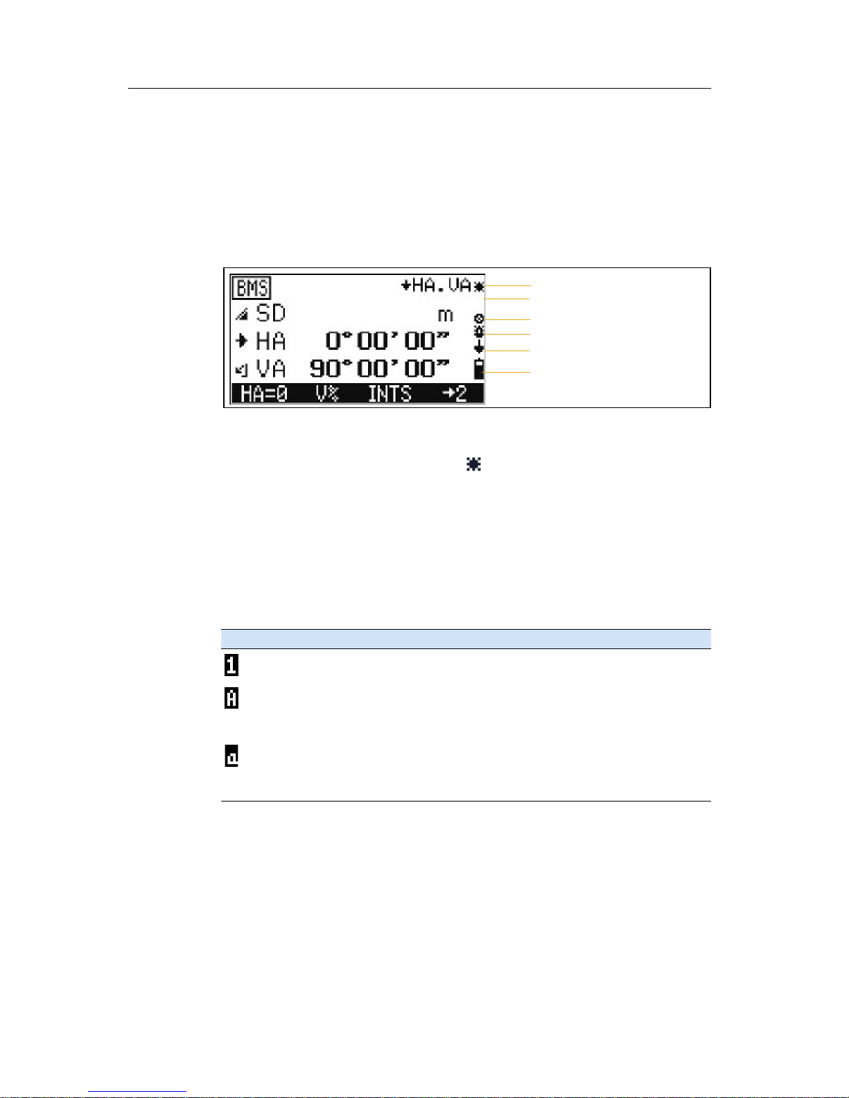
20.1 Status bar
The status bar appears on the right side of every screen. It contains indicators that
reflect the status of various system functions:
Laser pointer indicator
When the laser pointer is on, the indicator appears. When the laser pointer is off,
no indicator appears.
The laser pointer indicator appears when the measurement is made in the direct-reflex
mode. In this condition, the laser class is 3R.
Input mode indicator
The input mode indicator only appears when you are entering points or coordinates. It
shows the following data input mode:
Indicator Input mode
Input mode is numeric. Press a key on the number pad to enter the number
printed on the key.
Input mode is alphabetic (capital letters). Press a key on the number pad to
enter the first letter printed above the key. Press the key repeatedly to cycle
through all the letters assigned to the key. For instance, to enter the capital
letter O in alphabetic mode, press
[6] three times.
Input mode is alphabetic (lower case). Press a key on the number pad to enter
the first letter printed above the key. Press the key repeatedly to cycle through
all the letters assigned to the key. For instance, to enter the lower case letter o
in alphabetic mode, press
[6] three times.
Laser pointer indicator
Input mode indicator
DR/PR mode indicator
Backlight on indicator
Battery level indicator
Compensator indicator
Page 29

Trimble M3 Total Station User Guide 19
Overview of the Trimble M3 Total Station 2
DR/PR mode indicator
The mode indicator indicates the current measurement mode. The icon blinks when
you take a measurement.
Backlight-ON indicator
When the backlight is on, the indicator appears. When the backlight is off, no
indicator appears.
Compensator indicator
When the automatic compensator correction is set to on, the indicator appears.
When the automatic compensator correction is off, no indicator appears.
Battery level indicator
The battery level indicator shows the battery voltage level:
If the battery level is critically low, the following
message appears:
Indicator Measurement mode
Current measurement mode is DR-mode (Direct-Reflex mode).
Current measurement mode is PR-mode (Prism mode).
Indicator Battery level
Level 4 (full)
Level 3
Level 2
Level 1
Battery low
Note – When the Battery low icon starts to blink, the remaining battery level
is less than 10 minutes. Please replace the battery with a fully charged battery
immediately.
Page 30

2 Overview of the Trimble M3 Total Station
20 Trimble M3 Total Station User Guide
2.1 Software overview
There are two software menus, the main MENU and the HOT MENU.
21.1 MENU overview
To access the main MENU screen, press [MENU] and then select options from the menu
using the keypad. Use the MENU screen to access important functions and settings.
Menu item Sub-menu Description
1. Job Manager 1. New Create a new job. See Creating a new job, page 68.
2. Open Open an existing job. See Opening an existing job, page 70.
3. Delete Delete a job. See Deleting a job, page 70.
4. Ctrl Point Set a control point job. See Setting the Control Point job, page 71.
5. Info Show job information (including free space, recorded points). See
Displaying job information, page 72
2. Adjustment C&I Zero point adjustment for vertical scale, horizontal angle
corrections, and compensator. See Checking and adjusting the
compensator (C) and index (I), page 119.
3. Applications 1. Connect Distance See Connecting distance, page 96.
2. Remote Object See Remote object height, page 100.
3. Station + Offset See Station and offset, page 102.
4. Vertical Plane See Vertical plane, page 105.
5. Compute Area See Compute area, page 107.
Page 31

Trimble M3 Total Station User Guide 21
Overview of the Trimble M3 Total Station 2
4. Coordinates 1. Resection See Resection, page 74.
2. Known Station 1. Hz - known station setup by BS Azimuth input.
2. YX - Known station setup by XYZ to BS.
See , page 79.
3. Station elevation REM. See Station elevation, page 83.
4. Measure topo Eccentricity (softkey) - In/Out, Right/Left offset distance input,
height and frequency settings. See Eccentric measurement,
page 85.
Input dSD (softkey).
See Measure topo, page 83.
5. Stake Out 1. XY - stakeout by coordinate, 2D. See Stake out by coordinates
(XY or XYZ), page 87.
2. HD - stakeout by angle and distance, 2D. See Stakeout by angle
and distance (HD or HDh), page 89.
3. XYZ - stakeout by coordinate, 3D. See Stake out by coordinates
(XY or XYZ), page 87.
4. HDh - stakeout by angle and distance, 3D. See Stakeout by
angle and distance (HD or HDh), page 89.
5. RefLine 2D - stakeout points from a line defined by Sta and O/S.
See Stakeout by reference line, page 90.
6. DivLine 2D - stakeout points after dividing a line by equal
distances. See Stakeout by dividing line, page 91.
5. Setting - Instrument 1. Angle Set angle accuracy, display unit, VA reference and direction.See
Angle settings, page 34.
2. Distance Set distance accuracy and display unit. See Distance settings,
page 35.
3. Coord. System Set axis type and display order. See Coordinate system settings,
page 36.
4. Units Set temperature and pressure. See Units settings, page 36
5. Turn Off Set auto-power cut-off settings and sleep settings for the main
unit. See Turn Off settings, page 36.
6. Clock Set the built-in clock. See Clock settings, page 37.
7. Miscellaneous Set default input modes in the code and point name fields. See
Miscellaneous settings, page 37.
6. Settings - interface Set the recording format. See Configuring data recording and
external communication settings, page 38.
7. Data Transfer 1. MEM-Periph Download data.See Downloading internal memory to an office
computer, page 111.
2. Periph-MEM Upload data (coordinates).See Uploading data from an office
computer to the internal memory, page 113.
3. Upload Point List Upload point-number list. See Uploading a point name/number
list from the office computer, page 114.
4. Upload Code List Upload point-code list. See Uploading a point code list from the
office computer, page 114.
Menu item Sub-menu Description
Page 32

2 Overview of the Trimble M3 Total Station
22 Trimble M3 Total Station User Guide
21.2 HOT MENU overview
To ac ces s t he HOT MENU, press . In any measurement screen, you can use the HOT
MENU to change the point number and point code and the EDM mode, or check
recorded data.
2.2 Principles of display
The following are typical program screens:
• Basic Measurement Screen (BMS)
• Input screens
• Menu screens
Menu item Sub-menu Description
1. EDM Settings Set distance precision. See Distance measurement settings (EDM),
page 39.
2. DR / PR Mode Select measure mode. See Changing target mode (DR or Prism),
page 40.
3. Elec. level Display the bubble and change tilt correction. See Bubble level
display (electric level), page 40.
4. Sett. Corr. Prism const. Input prism constant. See Configuring error corrections, page 40.
Temperature Input temperature.
Pressure Input pressure.
Scale Input scale factor.
C&R corr. Setting for curvature and refraction correction.
Sea level corr. Select sea-level correction.
5. P/C Input point number and code to prepare for the next recording
point. See Selecting a point name and point code, page 41.
6. Target Select a target set (a combination of target height and measure
mode). See Selecting a target configuration, page 41.
7. Edit Internal Memory See Editing data, point number lists or point code lists, page 42.
Point Number List See Managing your list of point names, page 44.
Point code list See Managing your list of point codes, page 45.
Page 33

Trimble M3 Total Station User Guide 23
Overview of the Trimble M3 Total Station 2
22.1 Basic Measurement Screen (BMS)
The BMS is an observation screen. To take a measurement and store the point data,
press
[MEAS/ENT].
The bottom part of the screen is the softkey area. To use the softkeys, press the
function key directly below the softkey command. For example, to reset the horizontal
angle to zero
HA=0, press [F1].
The Status bar, page 18 shows indicators for the laser pointer, the character input
mode, operating mode, backlight and tilt status, and the battery level.
22.2 Input screen
An input screen enables you to enter data.
In an input screen, the status bar displays the current input mode and the softkeys
provide different input options.
In the example shown here, press
• [F1] <ABC> to change the input mode to capital alphanumeric letters
• [F2] List to show the point name list
• [F3] Stack to display the point stack
• [F4] o.k. to complete both the point name and point code input
Status bar area
Softkey area
Softkey area
Currently set to numeric
input mode
Page 34

2 Overview of the Trimble M3 Total Station
24 Trimble M3 Total Station User Guide
22.3 Menu screen
A menu screen gives a list of options. When you have selected a menu item, a
secondary menu screen or input screen appears.
To choose a menu item, use the number keys, or the
[^] or [v] arrow keys.
On a menu screen, a down-arrow on the right bottom corner of the screen indicates
that there are more items in the menu. To see the other menu items, press
[v].
2.3 Inputting data
23.1 Changing between alphanumeric and numeric input
You can enter characters into fields using the
numeric
<123> or alphanumeric <ABC>/<abc>
mode. A
1, A, or a in the sidebar indicates the
current input mode.
The default input mode is numeric.
• To change the input mode from numeric to
capital letter alphanumeric, press
[F1].
• To change the input from capital letter to
lower case alphanumeric, press
[F1].
• To change back to the numeric input mode,
press
[F1] again.
Note – The alphanumeric mode includes the plus and
minus sign.
Down arrow indicator
Page 35

Trimble M3 Total Station User Guide 25
Overview of the Trimble M3 Total Station 2
23.2 Stack
Use the stack function to input a previously used
string.
1. Press
[F3] Stack when you are in an input
screen. A window appears that contains the
current contents in the stack memory.
2. To select a string from the stack list, press
[^] or
[v] and then press [MEAS/ENT] to insert the selected
string in the input screen.
3. To cancel the process, press
[ESC].
Note – The stack list can hold up to 5 strings used for
recording points.
20.1 List
Use the list function to input a string from the
registered list. The system maintains two lists: one for
the point number (point name), and one for the point
code.
1. Press
[F2] List when you are in an input screen.
A window appears that contains the current
contents in the list memory.
2. To select a list, press
[^] or [v] and then press
[MEAS/ENT] to insert the selected string in the
Point number or Point code field.
3. To cancel the process, press
[ESC].
Note – The lists can hold up to 254 point number or point codes. When you have a large
number of items, you can group them by using the Layer functionality. See Adding a layer,
page 46.
Page 36

2 Overview of the Trimble M3 Total Station
26 Trimble M3 Total Station User Guide
Page 37

CHAPTER
3
Trimble M3 Total Station User Guide 27
Before Going to the Field 3
In this chapter:
Q Unpacking and packing the instrument
Q Charging and discharging the battery pack
Q Selecting a language
Q Changing regional configuration presets
Q Instrument settings
Page 38

3 Before Going to the Field
28 Trimble M3 Total Station User Guide
3.1 Unpacking and packing the instrument
Note – Handle the Trimble M3 total station carefully to protect it from shocks and
excessive vibration.
31.1 Unpacking the instrument
To unpack the instrument, grip the carrying handle and
carefully remove the instrument from the carrying case.
31.2 Packing the instrument
Note – Store the instrument with the battery pack
attached.
To pack the instrument back into the carrying case:
1. Set the telescope in the horizontal face-1
position.
2. Align the storage marks (W + + W) as shown
in the figure right.
3. Lightly fasten the clamp knobs.
4. Place the instrument in the carrying case.
Note – When packing the charger in the plastic carrying
case, make sure that you store it as shown on the sticker
inside the case. Make sure that the battery charger cable
is not pinched when you close the case cover.
3.1 Charging and discharging the battery pack
31.1 Safety notices
Before charging the battery pack, read the following warnings, cautions and notes.
C
WARNING – To charge the battery pack (BC-65), use only the battery charger that is
attached to the instrument. Do NOT use any other charger or you may cause the battery
pack to catch fire or rupture. The enclosed battery pack (BC-65) cannot be used with other
chargers, such as a charger with part number Q-7U/E or Q-7C.
WARNING – Do not cover the battery charger while the battery pack is being recharged.
The charger must be able to dissipate heat adequately. Coverings such as blankets or
clothing can cause the charger to overheat.
Mark
Mark
Mark
Page 39

Trimble M3 Total Station User Guide 29
Before Going to the Field 3
C
WARNING – Avoid recharging the battery pack in humid or dusty places, in direct
sunlight, or near heat sources. Do not recharge the battery pack when it is wet. If you do,
you may receive electric shocks or burns, or the battery pack may overheat or catch fire.
C
WARNING – Although the battery pack (part number BC-65) has an auto-reset circuit
breaker, you should take care not to short circuit the contacts. Short circuits can cause the
battery pack to catch fire or burn you.
C
WARNING – Never burn or heat the battery. Doing so may cause the battery to leak or
rupture. A leaking or ruptured battery can cause serious injury.
C
WARNING – Before storing the battery pack or battery charger, cover the contact points
with insulation tape. If you do not cover the contact points, the battery pack or charger
may short circuit, causing fire, burns, or damage to the instrument.
C
WARNING – The battery BC-65 is not waterproof on its own. Do not get the battery wet
when it is removed from the instrument. If water seeps into the battery, it may cause a
fire or burns.
Note – Charge the battery pack indoors where the ambient temperature is between 10 °C
and 40 °C (between 50 °F and 104 °F). If you try to charge the battery when the ambient
temperature is outside this range, the protective circuit will activate and prevent it from
being charged normally.
Note – After charging the battery pack, do not recharge it until it has been fully discharged.
Recharging a fully charged battery pack lowers its performance.
Note – To prevent malfunction, keep the charging plug clean.
Note – If the charger indicator (LED2) blinks orange and green after charging is started,
there could be a problem in the battery pack. Do not use or charge the battery pack any
further. Contact your dealer.
Note – If the ambient temperature drops below 10 °C (50 °F) while the battery pack is
charging, charging stops. When the ambient temperature rises above 10 °C (50 °F),
charging is resumed.
Note – If the charger indicators (LED1 and LED2) remain lit orange for more than three
hours while the ambient temperature was in the normal range (10 °C through 40 °C or
50 °F through 104 °F), there could be a problem in the battery pack. Do not use or charge
the battery pack any further. Contact your dealer.
Note – During the charge, the battery pack and charger will become warm. This is normal.
Note – After charging the battery pack, do not recharge it until it has been fully discharged.
Recharging a fully charged battery pack lowers its performance.
Note – If the battery pack is used at low temperatures (below -20 °C or -4 °F), its capacity is
reduced, and it will allow less operation time than a battery pack used at normal (room)
temperature.
Note – If a battery pack is not used for a long period, it cannot be charged to its full
capacity again.
Page 40

3 Before Going to the Field
30 Trimble M3 Total Station User Guide
Note – You can use a battery charger with part number Q-70U/E or Q-70C to partially
charge a battery pack with part number BC-65. However, these chargers cannot fully
charge the BC-65 battery pack.
31.2 Charging the battery pack
1. Connect the power plug on the charger to an AC power outlet.
2. Connect the charging plug on the charger cable to the charging connector on
the battery pack.
Both indicators on the charger (LED1 and LED2) turn on to orange, and
charging starts automatically.
When the battery pack is fully charged, the LED2 indicator turns to green.
To AC outl et
Charger for
Air holes
Power cord and
LED2
LED1
adapters
BC-80/65
Connector to
the charger
To BC-65 battery
pack connector
Page 41

Trimble M3 Total Station User Guide 31
Before Going to the Field 3
30.1 Detaching the BC-65 battery pack from the instrument
C
CAUTION – Avoid touching the contacts on the battery pack.
1. If the instrument is turned on, press [PWR] to turn it off.
2. Depress the battery mounting button while holding the battery pack.
30.1 Attaching the BC-65 battery pack to the instrument
C
CAUTION – If the battery pack is not attached securely, this could adversely affect the
watertightness of the instrument.
1. Before you attach the battery pack, clear any dust or other foreign particles from
the battery socket.
2. Fit the two projections at the bottom of the battery pack into the concave
sections at the bottom of the socket on the instrument.
3. Hold the instrument steady with one hand and push the battery pack against
the instrument.
4. Make sure that the battery mounting button is securely locked.
1 4
3
2
Page 42

3 Before Going to the Field
32 Trimble M3 Total Station User Guide
3.1 Selecting a language
The Trimble M3 total station provides three language
selections, depending on the language pack that you
have installed:
• Language pack 1: English, Russian, and Spanish
• Language pack 2: English, German, and French
Language pack 1 is the default language pack
installed at the factory. To have another language
pack installed, contact an authorized Trimble total
station service provider.
1. To select a different language, power on the
instrument and at the
TILT TELESCOPE
screen, press
[ESC] and then press [3].
The
Language Configuration screen
appears. The screen shows up to three languages
that are currently available.
The current language selection is highlighted.
2. Press
[^] or [v] to highlight the required language
and then press
[ENT].
The instrument reboots and displays the startup Tilt Telescope screen in the selected
language.
3.1 Changing regional configuration presets
You can quickly configure the Trimble total station to a pre-set combination of default
regional settings. The Regional Configuration screen appears only after the language is
selected.
To change the regional configuration pre-sets:
1. Follow the steps in Selecting a language, page 32.
After the instrument is rebooted and the
telescope is tilted, the
Regional
Configuration screen appears.
2. Press
[^] or [v] to highlight the required regional
settings and then press
[ENT].
Page 43

Trimble M3 Total Station User Guide 33
Before Going to the Field 3
3. If you do not want to change the current
settings, press
[ESC]. The instrument will
continue to use the last settings that were
configured.
The settings affected by the
REGIONAL CONFIGURATION screen are:
Table 3.2 Regional configuration pre-sets
Category Setting Europe International United States
Angle Accuracy 0.2 mg - 0.5 mg 1” 1”
Unit gon DMS DMS
VA-Reference Zenith Zenith Zenith
AZ-Zero-Direct North North North
HA Initialize OFF OFF OFF
Distance Accuracy 0.001 m 0.001 m 0.001 f
Unit Meter Meter US-feet
(survey feet)
Coord. System Axis Type X↑ → YN↑ → EN↑ → E
Displ. Order Y, X N, E N, E
Units Temp Centigrade (°C) Centigrade (°C) Fahrenheit (°F)
Press hPa mmHg In Hg
Turn Off Main Unit OFF OFF OFF
Sleep 5 minutes 5 minutes 5 minutes
Miscellaneous P Input <123> <123> <123>
C Input <ABC> <ABC> <ABC>
Add PT for S-O 0 0 0
Settings Interface Recording MEM/3 MEM/3 MEM/3
Rec. Mode All All All
Rec. Settings No No No
Format M5 Nikon Nikon
Parity None None None
Baud 4800 4800 4800
Position P 16 16 16
Position C 11 11 11
Position I 1 1 1
EDM Settings Mode PREC PREC PREC
Ave 1 1 1
Settings
correction
Prism constant -18mm -18mm -18mm
Scale 1.000000 1.000000 1.000000
C & R corr. 0.142 0.142 0.142
Sea level corr. OFF OFF OFF
Page 44

3 Before Going to the Field
34 Trimble M3 Total Station User Guide
3.1 Instrument settings
The required instrument settings can be divided into the following groups:
• Basic measurement settings – access the basic
measurement setting options from
[MENU] [5]
Settings Instrument. See Basic
measurement settings, page 34.
• Data recording and transfer related settings –
access the basic measurement setting options
from
[MENU] [6] Setting Interface. See
Configuring data recording and external
communication settings, page 38.
• Frequently used settings – the Trimble key is
available in most observation screens and is used
to change the EDM mode, point number/code,
and target and correction settings. You can also
activate bubble indication to check leveling, and
check and edit data from this menu.
See Frequently used settings (HOT MENU
settings), page 39.
31.1 Basic measurement settings
Press [MENU] [5] Settings Instrument to enter or
change the basic measurement settings.
Angle settings
1. From the
Settings Instrument menu,
select
[1] Angle,
To move from one line to the next, press
[v].
2. To change the settings in each line, press
[<] or [>]
and then press
[MEAS/ENT] to confirm the change.
Page 45

Trimble M3 Total Station User Guide 35
Before Going to the Field 3
The angle settings are:
Distance settings
1. From the
Settings Instrument menu,
select
[2] Distance,
To move from one line to the next, press
[v].
2. To change the settings in each line, press
[<] or [>]
and then press
[MEAS/ENT] to confirm the change.
The distance settings are:
Options
Accuracy Tr im bl e M 3 3 "D R
1" / 0.0002° / 0.2mg / 0.01M
5" / 0.001° / 1mg / 0.1M
10" / 0.005° / 5mg / 0.5M
Tri mb le M3 5" DR
1" / 0.0005° / 0.5mg / 0.01M
5" / 0.001° / 1mg / 0.1M
10" / 0.005° / 5mg / 0.5M
Unit DMS
Deg
gon
mil
V-Reference Zenith
Vertical
± Elev
AZ-Zero-Direct North
South
HA Initialize ON
OFF
Note – When HA Initialize is set to ON, the horizontal angle needs to be
initialized (by rotating alidade) every time the vertical index is initialized
(that is, when you turn the instrument on). By doing this, the azimuth
direction will be kept after rebooting the instrument.
Options
Accuracy 0.001 m / 0.001 ft
0.005 m / 0.01 ft
0.01 m / 0.02 ft
Unit Meter
United States foot (U-ft)
International foot (I-ft)
Page 46

3 Before Going to the Field
36 Trimble M3 Total Station User Guide
Coordinate system settings
1. From the
Settings Instrument menu,
select
[3] Coord-Syst,
To move from one line to the next, press
[v].
2. To change the settings in each line, press
[<] or [>]
and then press
[MEAS/ENT] to confirm the change.
The coordinate system settings are:
Units settings
1. From the
Settings Instrument menu,
select
[4] Units,
To move from one line to the next, press
[v].
2. To change the settings in each line, press
[<] or [>]
and then press
[MEAS/ENT] to confirm the change.
The coordinate system settings are:
Turn Off settings
This option controls power saving.
1. From the
Settings Instrument menu,
select
[5] Turn Off,
To move from one line to the next, press
[v].
2. To change the settings in each line, press
[<] or [>]
and then press
[MEAS/ENT] to confirm the change.
Options
Axis Type X↑ → Y
Y↑ → X
N↑ → E
Displ.Order Y, X
X, Y
N, E
E, N
Options
Temperature Celsius
Fahrenheit
Pressure mmHg
hPa
inHg
Page 47

Trimble M3 Total Station User Guide 37
Before Going to the Field 3
The power savings settings are:
Clock settings
1. From the
Settings Instrument menu,
select
[6] Clock,
To move from one element of the date or time
field ( for example from the year to the month
field), press
[v], [^], or [MEAS/ENT].
2. To change the settings of each date or time
element, press
[<] to select a character and then
use the keypad to enter a number. Press
[v] to
move to the next element.
3. Press
[MEAS/ENT] to confirm the change.
The clock settings are:
Miscellaneous settings
1. From the
Settings Instrument menu,
select
[7] Misc,
To move from one line to another press
[v].
2. To change the settings in each line, press
[<] or [>]
and then press
[MEAS/ENT] to confirm the change.
Options
Main Unit OFF
10 min
30 min
Sleep OFF
1 min
3 min
5 min
Options
Date Enter in the order Year > Month > Day
Time Enter in the order Hour > Minutes (24-hour clock)
Page 48

3 Before Going to the Field
38 Trimble M3 Total Station User Guide
The miscellaneous settings are:
30.1 Configuring data recording and external communication settings
1. Press [MENU] [6] Settings Interface to set
up data recording/transfer related settings.
To move from one line to the next, press
[v].
2. To change the settings in each line, press
[<] or [>]
and then press
[MEAS/ENT] to confirm the change.
The setting options are:
Options
P Input 123
ABC
abc
C Input 123
ABC
abc
Note – P Input and C Input are the settings used to define the
default input mode when you enter a point number or name
(P Input) and point code (C Input). For example, if you often use a
point name such as K-101 or T3, you can change the setting to start
entering the point name in alphabetic mode.
S-O Add PT 0 - 999999 (numeric input)
Note – This field is a setting for recoding a point in stakeout
functions. It is used to specify an integer that is added to the point
number being staked to generate a new number for recording the
staked point. The default value is 0. For example, when you stake
out PT3 with an Add Constant of 1000, the default number for
stakeout recording is PT1003.
Options
Rec. Data Type MEM/1 /2 /3 - record data to the internal memory, where:
• /1 records measured values
• /2 records computed values
• /3 records both measured and computed value
V24/1 /2 /3 - output data to external device via the RS232 interface,
where:
• /1 outputs measured values
• /2 outputs computed values
• /3 outputs both measured and computed value
OFF - no data recorded
Rec. Mode All
Confirm
Rec. Settings Yes
No
Page 49

Trimble M3 Total Station User Guide 39
Before Going to the Field 3
30.1 Frequently used settings (HOT MENU settings)
Press the Trimble key to access the HOT MENU.
B
Tip – When you hold down the Trimble key for one
second in any observation screen, a shortcut screen
appears that enables you to enter the point, code, target
height, and prism constant.
Distance measurement settings (EDM)
1. Press
[1] in the HOT MENU screen to open the
EDM Settings screen.
2. Press
[<] or [>] to change the Mode setting. The
options are
PREC/STD where:
PREC is precise measurement mode
STD is fast measurement mode
3. Press
[v] to move to the AVE field. AVE is the
number of measurements to average when
computing the measured distance value. Enter a
number between 1 and 99.
4. To return to the
HOT MENU screen, press [ESC].
Format (output format) M5, see M5 data format, page 130
Nikon, see Nikon data format, page 142
Parity None
Even
Odd
Baud rate 1200
2400
4800
9600
19200
38400
Position P (only for M5
format)
1 - 16
Position C (only for M5
format)
1 - 23
Position I (only for M5
format)
1 - 21
Options
Page 50

3 Before Going to the Field
40 Trimble M3 Total Station User Guide
Changing target mode (DR or Prism)
Press
[2] in the HOT MENU screen to change the current
EDM mode. For example, if you are currently in Prism
measurement mode (
PR), press [2] to change the mode
to Direct-Reflex mode (
DR).
B
Tip – When you change the DR/PR mode, the prism
constant and target height is updated using the setting
value in [6] Target. In DR mode, the prism constant and
target height for DR is used. In PR mode, the values are
the last ones used in PR mode.
Bubble level display (electric level)
1. Press
[3] Elec. Level in the HOT MENU
screen to view the bubble level display.
2. To change the tilt compensation settings, press
[<]
or
[>].
3. To return to the
HOT MENU screen, press [ESC].
Configuring error corrections
1. Press
[4] in the HOT MENU screen to open the
Settings Corrections screen. There are
seven settings related to distance corrections.
2. In the first settings screen
Correction is
updated when you change the temperature
and/or pressure value.
3. Do one of the following:
– To display the next screen, press
[v] when
you are in the
Pressure field.
– To use values from the stack, press
[F3] Stack in any numeric input field.
– To finish the settings, press
[F4] o.k.
4. Press [ESC] to return to the HOT MENU screen.
Table 3.3 Allowable values for error corrections
Setting Input range
Prism constant -999 – 999 (numeric input)
Temperature -40 °C – 70 °C
Pressure 440 hPa – 1460 hPa
Scale 0.995000 – 1.00500
C&R corr. 0.132, 0.142, 0.200, or OFF
Sea level corr. ON/OFF
Page 51

Trimble M3 Total Station User Guide 41
Before Going to the Field 3
Selecting a point name and point code
1. Press
[5] in the HOT MENU screen to open the
Point Number/Point Code screen.
2. Do one of the following:
– To change the input mode, press
[F1] <ABC>.
– To select the input from the list, press
[F2] List.
– To select the input from a previously used
point name or code, press
[F3] Stack.
3. Then do one of the following:
– To return to the screen in which you
pressed , press
[F4].
– To return to the
HOT MENU screen, press
[ESC].
Selecting a target configuration
1. Press
[6] in the HOT MENU screen to open the
Set Target screen.
2. Do one of the following:
– To move the cursor in the target list, press
[^]
or [v] or [1] – [5] and then press [MEAS/ENT] to
select the highlighted item.
–Press
[F2] Edit to edit the target settings,
see Editing target settings, page 41.
3. To select the highlighted target, press
[F4] o.k..
Editing target settings
1. Press [F2] Edit in the Set Target screen. The
Edit Target screen appears.
2. Do one of the following:
– Use the keypad to enter a new value.
– To use values from the stack, press
[F3] Stack.
– To return to the previous screen, press
[ESC].
3. To finish the edit, press
[F4] o.k..
Note – Input the value that is shown on the prism into the
Prism const. field.
Page 52

3 Before Going to the Field
42 Trimble M3 Total Station User Guide
Editing data, point number lists or point code lists
1. Press
[7] in the HOT MENU screen to open the
Edit screen.
2. Do one of the following:
– To view and edit data stored in the memory,
press
[F1]. See Viewing and editing data in
internal memory, page 42.
– To edit the point number list, press
[F2]. See
Managing your list of point names, page 44.
– To edit the point code list, press
[F3]. See
Managing your list of point codes, page 45
3. To return to the
HOT MENU screen, press [ESC].
Viewing and editing data in internal memory
This screen reports the current status of the internal
memory:
• Free memory indicates how many more lines
you can record.
• Last address is the address of the last
recorded line in the internal memory.
Do one of the following:
• To open the view data screen, press [F1] Disp.
See Reviewing stored data, page 43.
• To delete data lines, press [F2] Del. See Deleting
data, page 43.
• To input coordinate data, press [F3] Inp.
Page 53

Trimble M3 Total Station User Guide 43
Before Going to the Field 3
Reviewing stored data
1. Press [F1] Disp in the Internal memory
screen.
2. Do any of the following:
– To edit point number and code, press
[F1]
C+P.
– To search a point by point name or number,
press
[F2] ?P.
– To search a point by point code, press
[F3]
?C.
– To search a point by address, press
[F4] ?A.
– To display the previous data line in the
internal memory, press
[^].
– To display the next data line in the internal
memory, press
[v].
– To return to the previous screen, press
[ESC].
Deleting data
1. Press [F2] Del in the Internal memory
screen to delete data lines,
2. Do any of the following:
– To delete all points in the current job, press
[F1] All.
– To define the point so that you can delete
by point number, press
[F2] ?P.
– To define the point so that you can delete
by point code, press
[F3] ?C.
– To define the point so that you can delete
by address, press
[F4] ?A.
Note – When the address is specified by ?P, ?C, or ?A,
everything, from the specified data line to the end of the
file, will be deleted.
Page 54

3 Before Going to the Field
44 Trimble M3 Total Station User Guide
Searching your data
1. Press [F3] ? in the View data screen to open the
Search from Job screen.
2. Do one of the following:
– To search a point by point name or number,
press
[F2] ?P. When you have selected or
entered a point name or number, press
[MEAS/ENT].
– To search a point by point code, press
[F3] ?C.
– To search a point by address, press
[F4] ?A.
The search result screen appears.
3. Do one of the following:
– To search another point with the same
condition, press
[F3] ?↓.
– To define a new search, press
[ESC] to return
to the previous screen.
Managing your list of point names
This screen shows the current point name list. Press the
[^] or [v] key to select the point name or number, or a
layer that you want to edit or delete.
Do one of the following:
– To delete the highlighted point name or
number, press
[F1] DEL. See Deleting a point
name or number, page 45.
– To edit the highlighted point name or
number, press
[F2] Edit. See Editing a point
name or number, page 45.
– To add a point name or number, press
[F3]
Add. See Adding a point name or number,
page 45.
– To return to the previous screen, press
[ESC].
Page 55

Trimble M3 Total Station User Guide 45
Before Going to the Field 3
Editing a point name or number
1. Press [F2] Edit in the point number list screen.
The
Edit Point Number screen appears.
2. Enter the required name or number. Press
[F1]
<abc> to change the input mode.
3. Press
[MEAS/ENT]. A confirmation screen appears.
Do one of the following:
– To return to the list without any change,
press
[F1] No.
– To accept the change and update the list,
press
[F4] Yes.
Deleting a point name or number
1. Highlight an item in the point number list screen
and then press
[F1] DEL. A confirmation screen
appears.
2. Do one of the following:
– To return to the list without deleting the
item, press
[F1] No.
– To delete the item, press
[F4] Yes.
Adding a point name or number
1. Press [F3] Add in the point number list screen.
The
Add screen appears.
2. Do one of the following:
– Use the keypad to enter a new value.
– To change the input mode, press
[F1] <ABC>.
– To return to the previous screen, press
[ESC].
3. Press
[MEAS/ENT] to update the list.
Managing your list of point codes
This screen shows the current point code list. Press
[^] or
[v] to select the point name or number, or a layer that
you want to edit or delete.
Note – A layer is a group of point codes with an arrow
showing at the end of the string.
Page 56

3 Before Going to the Field
46 Trimble M3 Total Station User Guide
All the procedures that are used to edit a point name
list, are also used to edit a point code. See Managing
your list of point names, page 44. In addition, you can
add a layer. See Adding a layer, page 46.
Adding a layer
A layer is a folder to categorize a set of point codes.
This is especially useful when you have many codes
and need to quickly find and input the point code that
you want to use in the field.
1. Press
[F4] Layer in the point code list screen.
The
Add Layer screen appears.
2. Do one of the following:
– Use the keypad to enter a new value.
– To change the input mode, press
[F1] <abc>.
– To return to the previous screen, press
[ESC].
3. Press
[MEAS/ENT] to update the list.
Page 57

CHAPTER
4
Trimble M3 Total Station User Guide 47
Getting Started in the Field 4
In this chapter:
Q Setting up the tripod
Q Centering
Q Leveling
Q Focusing the telescope
Q Setting the measurement mode and preparing the target
Q Turning the instrument on and off
Page 58

4 Getting Started in the Field
48 Trimble M3 Total Station User Guide
4.1 Setting up the tripod
C
CAUTION – The tops of the tripod ferrules are very sharp. When handling or carrying the
tripod, take care to avoid injuring yourself on the ferrules.
Note – Do not carry the instrument while it is attached to a tripod.
1. Open the tripod legs far enough for the instrument to be stable.
2. Locate the tripod directly over the station point. To check the tripod's position,
look through the center hole in the tripod head.
3. Firmly press the tripod ferrules into the ground.
4. Level the top surface of the tripod head.
5. Securely fasten the thumb screws on the tripod legs.
6. Place the instrument on the tripod head.
7. Insert the tripod mounting screw into the center hole of the base plate of the
instrument.
8. Tighten the tripod mounting screw.
4.1 Centering
When you center the instrument, you align its central axis precisely over the station
point. To center the instrument, you can either use the optical plummet or a plumb
bob. The plumb bob is sold separately.
41.1 Centering with optical plummet
Note – If you require high accuracy, check and adjust the optical plummet before you
center the instrument. For detailed instructions, see Checking and adjusting the optical
plummet, page 117.
1. After setting up the instrument on the tripod, look
through the optical plummet and align the reticle with
the station point. To do this, turn the leveling screws
until the center mark of the reticle is directly over the
image of the station point.
2. While supporting the tripod head with one hand, loosen
the tripod leg clamps and adjust the lengths of the legs
until the air bubble is in the center of the circular level.
3. Tighten the tripod leg clamps.
4. Use the plate level to level the instrument. See Leveling, page 49. Look through
the optical plummet to check that the image of the station point is still in the
center of the reticle mark.
Page 59

Trimble M3 Total Station User Guide 49
Getting Started in the Field 4
5. If the station point is off center, do one of the following:
– If the station point is slightly off center, loosen the tripod mounting screw
and then center the instrument on the tripod. Use only direct movement to
center the instrument. Do not rotate it.
When the instrument is centered, tighten the mounting screw.
– If the displacement of the station point is major, repeat this procedure from
Step 2.
4.1 Leveling
When you level the instrument, you make the vertical
axis of the instrument exactly vertical.
To level the instrument, use the plate level.
1. Loosen the upper plate clamp.
2. Rotate the alidade until the plate level is parallel
with any two of the leveling screws (B and C).
3. Use leveling screws B and C to move the bubble
into the center of the level.
4. Rotate the alidade approximately 90°.
5. Use leveling screw A to move the bubble into the
center of the level.
6. Repeat Step 1 through Step 5 to center the bubble
in both positions.
7. Rotate the alidade 180°.
8. If the bubble in the plate level remains centered, the instrument is level. If the
bubble moves off center, adjust the plate level. For detailed instructions, see
Checking and adjusting the plate level, page 116.
Page 60

4 Getting Started in the Field
50 Trimble M3 Total Station User Guide
4.1 Focusing the telescope
C
WARNING – Never look at the sun through the telescope. If you do, you may damage or
lose your eyesight.
When you sight the instrument, you aim the telescope at
the target, bring the target image into focus, and align the
image with the center crosshairs of the reticle.
Note – In DR-mode, the center circle of the crosshair is the
beam passing area. The diameter is about 15 cm at 100 m
distance from the instrument.
To sight the instrument:
1. Adjust the diopter:
a. Aim the telescope at a blank area, such as the
sky or a piece of paper.
b. Looking through the eyepiece, rotate the
diopter ring until the reticle crosshairs are in
sharp focus.
2. Eliminate parallax:
a. Aim the telescope at the target image.
b. Rotate the focusing ring until the target image is in sharp focus on the
reticle crosshairs.
c. Move your eye vertically and laterally to check whether the target image
moves relative to the reticle crosshairs.
If the target image does not move, there is no parallax.
d. If the target image does move, rotate the telescope focusing ring. Then
repeat from Step c.
3. Rotate the tangent screw. The final turn of the tangent screw should be in a
clockwise direction, to align the target accurately on the center crosshairs.
Center
crosshairs
Diopter ring
Telescope
focusing ring
Page 61

Trimble M3 Total Station User Guide 51
Getting Started in the Field 4
4.1 Setting the measurement mode and preparing the target
C
WARNING – Observe all other warnings and cautions. See Safety and Warnings, page iii.
The Trimble M3 total station has two measurement modes: Prism mode (Prism) and
Direct Reflex mode (
DR). To change the mode at any time from any observation screen,
press and then press
[2]. See also Changing target mode (DR or Prism), page 40.
The Trimble M3 total station is Laser Class 3R in the Reflectorless mode, is Laser Class
1 in the Prism mode.
Don’t sight the Prism in Reflectorless mode.
Ta bl e 4 .4 describes how to set the measurement mode depending on the target you
want to measure.
41.1 Measurement with a prism
As the Trimble M3 total station is extremely sensitive, multiple reflections on the prism
surface can sometimes cause a significant loss in accuracy.
To maintain the accuracy of your measurements:
• Do not use a prism with scratches, a dirty surface, or a chipped center. Trimble
recommends that you use prisms with thin edges as shown below.
Table 4.4 Measurement modes
Targ et Targ e t s ett i ng s Indicator on status bar
Prism, reflector sheet Prism (Prism mode)
Other, reflective materials DR (Direct-Reflex mode)
✓
✕
✕
Thin edges
Chipped center
Thick edges
Page 62

4 Getting Started in the Field
52 Trimble M3 Total Station User Guide
• When measuring a short distance, incline the prism slightly so that the EDM
can ignore unnecessary reflections on the prism surface, as shown below.
Hold the prism securely in place and do not move while taking measurements.
In Prism mode, in order to avoid false measurements on objects other than the prism
or reflector-sheet, targets that are less reflective than the prism or reflector sheet are
not measured. Even if you start a measurement, measured values are not displayed. To
measure less reflective objects, use the Direct-Reflex mode.
41.2 Measurement in Direct-Reflex mode
The intensity of the reflection from the target determines the distance the Trimble M3
total station can measure in this mode. The color and condition of the target surface
also affect the measurable distance, even if the targeted objects are the same. Some
less-reflective targets may not be measured.
Ta bl e 4 .5 describes some examples of targets and approximate measurable distances.
Measurable distances may be shorter or measurement intervals may be longer in the
following cases:
• the angle of the laser against the target is small
• the surface of the target is wet
In direct sunlight, the measurable distance may be shorter. In this case, try to throw a
shadow on the target.
Targets with completely flat surfaces, such as mirrors, cannot be measured unless the
beam and the target are perpendicular to each other.
Make sure there are no obstacles between the instrument and the target when taking
measurements. When you need to take measurements across a road or a place where
vehicles or other objects are frequently moving, take several measurements to a target
for the best result.
Table 4.5 Targets and measurement distances
Targ et You can measure approximately...
Traffic signs, reflectors 500 meters (1640 feet)
Paper (white), veneer (new) 300 meters (990 feet)
Wall (brightly painted), brick 100 to 200 meters (330 to 660 feet)
Not completely square to
the sighting axis
Completely square to
the sighting axis
Page 63

Trimble M3 Total Station User Guide 53
Getting Started in the Field 4
4.2 Turning the instrument on and off
42.1 Turning on the instrument
1. To turn on the instrument, press [PWR]. The
start-up screen appears. This screen shows the
version of the program.
2. When you tilt the telescope, current settings of
temperature, pressure, prism constant, and scale
appear for about two seconds.
3. The
Rec Current Settings screen
appears. Do one of the following:
– To skip recording the current instrument
settings, press
[F1] No.
– To record current settings, press
[F4] Yes. If
you select Yes, the Recording to screen
appears.
Note – To initialize the horizontal angle every time you
power on, set the HA initialize setting to ON. Select
MENU/Settings Instrument/Angle.
4. After this, the instrument will automatically1
return to the screen that was showing before the
instrument powered off.
40.1 Turning off the instrument
To turn the instrument off, press [PWR] and then press
[ENT].
Then do one of the following:
Press to...
[ENT] again turn off the instrument
[F2] Reset reboot the program and restart the instrument
Note – If you press the Reset softkey, the software is rebooted and the
Basic Measurement Screen (BMS) appears.
[F4] Sleep put the program into power-saving mode, see Sleep mode, page 54
[ESC]
cancel the power-off process and return to the previous screen
Page 64

4 Getting Started in the Field
54 Trimble M3 Total Station User Guide
40.2 Sleep mode
If you press [F4] Sleep in the Press ENT OFF
screen, or enable the Power Save setting (select
MENU/[5] Settings Instrument/ [5] Turn-off),
the instrument goes into sleep mode.
When the instrument is in sleep mode, it wakes up if
any of the following occurs:
• You press any key.
• The instrument receives any remote control
command via the serial interface.
• You rotate the alidade.
• You tilt the telescope.
Page 65

CHAPTER
5
Trimble M3 Total Station User Guide 55
Basic Measurement Screen 5
In this chapter:
Q Measurement mode
Q Changing the screen display
Q Changing the distance unit
Q Taking measurements
Q Setting the horizontal angle (HA)
Q Setting target height (th) and instrument height (ih)
Q Setting the station elevation
Q Measuring edges and corners using the Intersection program (INTS)
Page 66

5 Basic Measurement Screen
56 Trimble M3 Total Station User Guide
5.1 Measurement mode
The Basic Measurement Screen BMS appears after the
Tilt Telescope screen. The Basic Measurement
Screen displays the current angle measurements and
most recent distance measurement.
The measurement (MEAS) indicators are shown on the
left of the screen. They are:
Table 5.6 Measurement mode indicators
SD
Slope distance
HA
Horizontal angle
Clockwise Counter-clockwise
VA
Vertical angle
Zenith Vertical ± Elev.
HD
Horizontal distance
h
Height
V%
Percent grade
Page 67

Trimble M3 Total Station User Guide 57
Basic Measurement Screen 5
5.2 Changing the screen display
There are four BMS screens. To move between
the screens, press
[^] or [v].
The items that will appear in the next screen are
shown in the screen header (upper right corner).
You can also do the following using the Trimble menu
key and function keys:
• To access the HOT MENU screen from any BMS
screen, press .
• From the startup BMS screen, press [F1] to go to
HA=O screen, see Setting the horizontal angle
(HA), page 60.
[v]
[^]
[v]
[^]
[v]
[^]
Page 68

5 Basic Measurement Screen
58 Trimble M3 Total Station User Guide
• To change VA to V %, press [F2] in either of the
first two screens.
• To set the target or instrument heights, go to the
th/ih input screen. Press [F2] th/ih in the
third and fourth screens. See Setting target height
(th) and instrument height (ih), page 60.
• To go to the INTS screen (Intersection function
menu), press
[F3] INTS. See Intersection, page 65.
• There are three sets of data. To display a different
set of data, press
[F4] until the required data
appears.
5.3 Changing the distance unit
To change the distance unit:
1. Press
[F4] in the BMS screen. The second set of
data appears.
2. To change the distance unit press
[F1].
– When the unit is set to meters, the softkey
is set to
U-ft.
– When the unit is set to US-feet, the softkey
is set to
I-ft.
– When the unit is set to international feet,
the softkey is set to
m.
Page 69

Trimble M3 Total Station User Guide 59
Basic Measurement Screen 5
5.1 Taking measurements
To take a measurement in any BMS screen:
1. Press
[MEAS/ENT]. The prism constant value
appears in small characters until the measured
value appears.
Note – When the average count is set to more than one,
the intermediate measurement process is shown in the SD
field by numbers in parentheses. For example if the
average count is set to 5, the following appears on screen
(1/5) (2/5) (3/5) (4/5) (5/5). To set the average count, press
, select
[1] and set the Ave field to the required count.
2. To stop measurement, press
[F1] Stop or [ESC].
3. If the Recording mode is set to Confirm
(
[Menu] / [6]) the Record As screen appears and
you are prompted to record the measurements.
To record the measurements, press
[F4] Yes.
Note – If the Rec. Mode is set to All, the
Recording to
Adr:xxxxx screen appears. See Configuring data
recording and external communication settings, page 38.
50.1 Tracking mode
Tracking mode initiates a continuous measurement
until you stop measurement by pressing
[F4] END.
To initiate tracking mode, press
[MEAS/ENT] for one
second.
Note – To change the EDM mode, press , select
[2] and
select the required mode.
Page 70

5 Basic Measurement Screen
60 Trimble M3 Total Station User Guide
5.1 Setting the horizontal angle (HA)
To set or reset the horizontal angle:
1. Press
[F1] HA=0 in any BMS screen. The HA=0
screen appears.
2. Sight the target and press
[MEAS/ENT] to set or reset
the horizontal angle.
5.1 Setting target height (th) and instrument height (ih)
To set the target height and instrument height:
1. Press
[F2] th/ih in the third or fourth BMS
screen.
The
STN Elevation screen appears. The
current values for target height (
th), instrument
height (
ih). and the Z-coordinate of the station
point (
Zs) appear.
2. Do one of the following:
– To activate the station elevation function,
press
[F1] Z. See Setting the station
elevation, page 61.
– To input target height, press
[F2] th.
– To input the instrument height and/or a
new height for station-Z, press
[F3] ih/Zs.
See Instrument height (ih) and station-Z
coordinate (Zs), page 62.
– To confirm the current value and return to
the previous screen, press
[F4] o.k..
Page 71

Trimble M3 Total Station User Guide 61
Basic Measurement Screen 5
5.1 Setting the station elevation
The station elevation function defines the Z coordinate
of the station point after you have set up the
instrument by 2D.
To activate the station elevation function, press
[F1] Z in
the
STN Elevation screen.
To set the station elevation:
1. Do one of the following:
– To start the program, press
[F1] Stat.
– To activate the Adjustment C&I program,
press
[F3] CHCK. See Checking and adjusting
the compensator (C) and index (I), page 119.
2. To select a benchmark point, do one of the
following:
– To select the benchmark point from the
internal memory (database), press
[F1].
– To input a new benchmark point, press
[F3].
3. Enter the station
Z coordinate value and press
[MEAS/ENT]. The Input ih screen appears.
Enter the instrument height
ih and press
[MEAS/ENT]. The Input th screen appears.
Enter the target height
th and press [MEAS/ENT].
The
Sight backsight point screen
appears.
Note – You can also pres s
[F3] in any input screen (when
you input Z, ih, or th) to select a previously input value
from the Stack.
4. To go directly to the bearing and distance
function, press
[F4] BeaDist. See Bearing-
Distance, page 63.
5. The
STN Elevation screen shows the result.
Do one of the following:
– To exit the program without saving the
result, press
[F1] No.
– To record the result on the screen and finish
the program, press
[F4] Yes.
Page 72

5 Basic Measurement Screen
62 Trimble M3 Total Station User Guide
50.1 Instrument height (ih) and station-Z coordinate (Zs)
To input instrument height (ih) and station Z
coordinates (
Zs):
1. Press
[F3] ih/Zs in the STN Elevation screen.
2. Select a method to input Station height.
– To input from recorded data, press
[F1]
Internal memory.
– To input directly using the keypad, press
[F3]
Input.
3. Input the Zs coordinate. Do one of the following:
– Enter the coordinates using the keypad and
then press
[MEAS/ENT].
– To use previous input, press
[F3] Stack,
select the required value and then press
[MEAS/ENT].
4. Input the instrument height. Do one of the
following:
– Enter the instrument height using the
keypad and then press
[MEAS/ENT].
– To use previous input, press
[F3] Stack,
select the required value and then press
[MEAS/ENT].
5. The STN Elevation screen shows the result. Do
one of the following:
– To exit the program without saving the
result, press
[F1] No.
– To record the result on the screen and finish
the program, press
[F4] Yes.
Page 73

Trimble M3 Total Station User Guide 63
Basic Measurement Screen 5
5.1 Measuring edges and corners using the Intersection program
(INTS)
To measure edges and corners, especially in DR mode,
Trimble recommends that you use the Intersection
program (INTS).
To access the
INTS screen, press [F3] INTS in a BMS
screen.
51.1 Bearing-Distance
Use this method when you want to shoot to the exact
corner of a pillar or wall, or when it is difficult to place a
target at the point you need to measure. You can first
set the angle by sighting the point and then take a
measurement to the closest point where the distance is
almost the same.
1. Press
[1] to open the Bearing-Dist. screen.
2. Press
[<] or [>] to change the Mode setting. The
options are
OFF/Once/Perm.
If Mode is set to
Perm you can continue using
this offset measurement until you escape from
the function.
3. Press
[F4] o.k..
4. Sight the point you need to record and press
[MEAS/ENT]. The horizontal and vertical angles are
fixed on the screen.
5. Find a target at the closest possible point and
press
[MEAS/ENT].
After taking a distance measurement, the BMS
screen appears from which you entered the INTS
program. The screen shows the new
measurements.
Note – When Record mode (Rec. mode) is set to Confirm,
a confirmation screen appears before you record a point.
See Tak ing mea surem ents, pag e 59.
Page 74

5 Basic Measurement Screen
64 Trimble M3 Total Station User Guide
50.1 Corner-Angle
Use this method to measure points, edges, and corners
on vertical planes. Any point of the plane can be
measured and measurements to points A and B can be
repeated.
1. Press
[2] in the INTS menu to open the
Corner-Angle screen.
2. Press
[<] or [>] to change the Mode setting. The
options are
OFF/Once/Perm.
If Mode is set to
Perm you can continue using
this offset measurement until you escape from
the function.
3. Press
[F4] o.k.
4. Sight point A and then press [MEAS/ENT].
5. Sight point B and then press
[MEAS/ENT].
6. Sight point P and then press
[MEAS/ENT].
7. If you want to repeat a measurement:
–Press
[F1] A to return to the point A
measurement screen.
–Press
[F2] B to return to the point B
measurement screen.
After you have completed your measurements,
the
BMS screen appears from which you entered
the
INTS menu. The BMS screen shows the new
measurements.
Page 75

Trimble M3 Total Station User Guide 65
Basic Measurement Screen 5
50.1 Intersection
Use this method to determine the intersection point of
two vertical planes.
1. Press
[3] in the INTS menu to open the
Corner-Angle. screen.
2. Press
[<] or [>] to change the Mode setting. The
options are
OFF/Once/Perm.
If
Mode is set to Perm you can continue using
this offset measurement until you escape from
the function.
3. Press
[F4] o.k.
4. Sight point A (on the first wall) and press
[MEAS/ENT].
5. Sight point B (on the same wall) and press
[MEAS/ENT].
6. When you have taken two measurements, sight
point C (on another wall) and press
[MEAS/ENT].
7. If you want to repeat a measurement:
–Press
[F1] A to return to the point A
measurement screen.
–Press
[F2] B to return to the point B
measurement screen.
After you have completed your measurements,
the
BMS screen appears from which you entered
the
INTS program. The BMS screen shows the
new measurements.
Page 76

5 Basic Measurement Screen
66 Trimble M3 Total Station User Guide
50.1 Eccentric Object
Use this method to determine the radius and the center
point of a vertical round object.
1. Press
[4] in the INTS menu to open the Ecc.
Object screen.
2. Press
[<] or [>] to change the Mode setting. The
options are
OFF/Once/Perm.
If
Mode is set to Perm you can continue using
this offset measurement until you escape from
the function.
3. Press
[F4] o.k.
4. Sight point A and press [MEAS/ENT].
5. Sight point B and press
[MEAS/ENT].
6. If you want to repeat a measurement, press
[F1] A
to remeasure to point A.
The calculated radius appears.
7. Do one of the following:
– To record the result, press
[F4] o.k.
– To change the point name or code before
you record the point, press .
– To return to the first screen without
recording data, press
[ESC].
Page 77

CHAPTER
6
Trimble M3 Total Station User Guide 67
Job Manager 6
In this chapter:
Q Creating a new job
Q Opening an existing job
Q Deleting a job
Q Setting the Control Point job
Q Displaying job information
Q Editing data
Page 78

6 Job Manager
68 Trimble M3 Total Station User Guide
The Trimble M3 total station is equipped with an intelligent data management system
called Job Manager. You can record survey data into a folder (a job) and categorize data
by day, by site, or zone-independent.
Up to 32 jobs can be created in the internal memory.
Use the Job Manager to open, create, delete, and manage jobs.
Note – The Trimble M3 total station can also operate without creating a job. In this case,
the system automatically creates a job called NONAME using the current instrument
settings.
To open the Job Manager, select
MENU [1].
6.1 Creating a new job
1. From the Job Manager menu, select [1] New.
2. In the
New Job screen, enter a job name and
press
[MEAS/ENT].
3. Enter the other job settings (11 settings
presented in three screens) by doing one of the
following:
– enter values using the keypad
– press
[<] or [>] to change settings
4. In the third screen, press
[F2] CREATE to create
the job.
Page 79

Trimble M3 Total Station User Guide 69
Job Manager 6
The job settings are:
Setting Options
Job name Consists of the date and a unique letter or number
Angle Unit DMS
Deg
gon
mil
VA-Reference Zenith
Vertical
±Elev.
AZ-Zero-Direct North
South
Dist.Unit Meter (m)
US feet (U-ft)
International feet (I-ft)
Coord.System YX
XY
NE
Coord.Display Y, X
X,Y
N,E
E,N
Temp.Unit Celsius
Fahrenheit
Press.Unit mmHg
hPa
inHg
Scale 0.995000~1.005000 (numeric input)
C&R Correction 0.132
0.142
0.200
OFF
Sea Level Correction ON
OFF
Page 80

6 Job Manager
70 Trimble M3 Total Station User Guide
6.1 Opening an existing job
1. From the Job Manager menu, select [2] Open.
A list of all jobs stored in the internal memory
appears in descending date order.
A star (*) appears next to the job that is currently
open.
An arrow indicates the control-point job (if
specified).
Note – For more information on control point jobs, see
Setting the Control Point job, page 71.
2. Press
[^] or [v] to select a job from the job list and
then press
[MEAS/ENT] to open the highlighted job.
Note – When you open a job, all job settings are
automatically imported to the instrument.
6.1 Deleting a job
C
CAUTION – There is no undelete function in the Job Manager. Before you press [F4] Yes on
this screen, make sure that the selected job is the one that you want to delete.
1. From the Job Manager menu, select [3]
Delete.
A list of all jobs stored in the internal memory
appears in descending date order.
2. Press
[^] or [v] to select the job that you want to
delete and then press
[MEAS/ENT].
3. A confirmation message appears. Press
[F4] Yes
to delete the selected job.
Page 81

Trimble M3 Total Station User Guide 71
Job Manager 6
6.1 Setting the Control Point job
Especially for stakeout or station setup work, a Control Point job can be used as an
independent coordinate file when you have a list of coordinate data on your office
computer.
Before you go to the field, upload or input the list of coordinate data to a Control Point
job. See also Uploading data from an office computer to the internal memory, page 113.
In the field, create a working job and set the Control Point job by the process described
below.
If you search for a point when the Control PT job is specified, and the system cannot
find the point in the current job, the Control PT job is also searched. If the point is
found in the Control PT job, it is copied to the current job.
A control job has the same format as a standard job. You can open and modify it like
any other job, and you can use it to record any measured data when you open it as a
current job.
To identify the Control Point file, do the following:
1. From the
Job Manager menu, select [4] Ctrl
Point.
A list of all jobs stored in the internal memory
appears in descending date order.
2. Press
[^] or [v] to select the job to which you want
to assign a control point and then press
[MEAS/ENT].
3. A confirmation message appears. To assign the
control point job, press
[F4] Yes.
4. To cancel the assigned control point job, open
the job list again, select the currently assigned
control point job, and press
[MEAS/ENT].
5. A confirmation message appears. To cancel the
assigned control point job, press
[F4] Yes
Page 82

6 Job Manager
72 Trimble M3 Total Station User Guide
6.1 Displaying job information
1. From the Job Manager menu, select [5] Info.
A list of all jobs stored in the internal memory
appears in descending date order.
2. Press
[^] or [v] to select the job for which you want
to display job information and then press
[MEAS/ENT].
3. The following fields appear:
4. Press
[MEAS/ENT] again to return to the Job
Manager menu.
6.1 Editing data
To access the editor, press and then select [7] Edit. See Editing data, point number
lists or point code lists, page 42.
Field Description
Lines Lines of currently stored records.
Free memory Number of records that can be stored additionally.
Created The date on which this job was created.
Modified The date on which the latest changes to the job where made.
Page 83

CHAPTER
7
Trimble M3 Total Station User Guide 73
Coordinates 7
In this chapter:
Q Resection
Q Known Station
Q Station elevation
Q Measure topo
Q Stakeout
Page 84

7 Coordinates
74 Trimble M3 Total Station User Guide
7.2 Resection
A resection sets up the station using angle/distance measurements to known points.
If it is not possible to occupy a point with a known position in order to sight the points
to be surveyed or set out, you can carry out a free stationing (or resection). If all
backsight points have a known height, the Z coordinate can be determined
simultaneously.
A maximum of 10 points can be measured. Measurements can be distance and angle,
or angle only. Calculations starts automatically when enough measurements are taken.
At least two sets of distance and angle measurement are required to determine the
station coordinate. After at least two measurements are taken, approximate
coordinates are calculated and residuals are displayed.
You can delete poor observations and recalculate if necessary. You can also select the
backsight (BS) point.
To go to the 3D station setup, press
[F1] with. To go to the 2D station setup, press [F3]
without press [ESC] to return to the Coordinates menu.
Note – The “3-D station setup” is also referred to as "known height" and "Z-coordinate".
Known point 1
Known point 2
Instrument
height
Station point
Z
Y
Page 85

Trimble M3 Total Station User Guide 75
Coordinates 7
When you select [1] Resection in the
Coordinates menu screen, you are prompted to
select 2D setup
without or 3D setup with before
starting the resection function.
1. Press
[F1] with in the Stationing of
elev. screen. You are prompted to input the
instrument height (ih).
2. Use the number keys to input the
ih value and
then press
[MEAS/ENT].
3. The Record as screen appears. Press [F4] Yes.
4. The
Resection screen appears.
A and B are backsight points with known
coordinates. S is the station. The coordinates of S
will be calculated after the measurement is
completed.
5. Press
[F1] A to take a measurement to Point A.
6. Sight point A and then press
[MEAS/ENT].
7. Do the following:
– The previously set target height will be used
with this measurement. If you need to
change the height of the target, in the
Backsight Point A screen, press [F2]
th.
– Alternatively, open the bearing and
distance screen, press
[F4] BeaDist. See
Bearing-Distance, page 63.
B
Tip – To change the point name, press .
After you have taken the measurement to point A, the
box for point A changes to a black box, which means
that the measurement is done.
Page 86

7 Coordinates
76 Trimble M3 Total Station User Guide
8. You can now either proceed with point B
measurement, or remeasure point A. Do one of
the following:
– To take a measurement to point B, press
[F2]
B.
–To remeasure point A, press
[F1] A.
After at least two measurements, approximate
coordinates are calculated and the deviation to
the current measurement appears:
–
vy: residual in Y-direction
–
vx: residual in X-direction
–
vz: residual in Z-direction
Based on the quality of your residual data, you
may want to add more points to the resection, or
remeasure your last point (point B).
Note – If the angle between known point A and known
point B (measured from the station point) is extremely
acute or extremely oblique, the resulting solution will be
less reliable geometrically. For geometric reliability, select
known point locations (or station point locations) that are
widely spaced.
9. Do one of the following:
– To remeasure to point B, press
[F1] B.
– To measure to the next point, press
[F2] C.
– To finish observation and proceed to the
Residual screen, press
[F4] END.
After completing the observation, the solution
residuals for each point are displayed for review. You
can delete points from the solution, add more points to
the calculation, or accept the current points.
10. In the Residuals check screen, do one of the
following:
– To show the previous or next point
observation result, press
[^] or [v].
– To add more points to the observation,
press
[F1] More.
Page 87

Trimble M3 Total Station User Guide 77
Coordinates 7
– To delete the point shown in this screen
( for example because of large residuals),
press
[F3] Del.
– To accept the current points and proceed to
the next screen, press
[F4] o.k..
11. The
Station Coordinates screen displays
the current station solution.
B
Tip – From the Station Coordinates screen or Scale screen,
you can change a point name or code or verify data by
pressing .
12. To accept the computed station coordinates,
press
[F4] o.k. in the Station
Coordinates screen.
The
Resection screen shows a quality
summary. These values indicate how good your
computed station coordinates fit with the points
used in the resection. For example, if your are
using ground coordinates, and your scale value,
m, is close to 1, you have established good
control in your station setup.
13. In the
Resection screen, do one of the
following:
– To return to the observation screen, press
[F1] Rept.
Note – If you decide to go back and remeasure the
corresponding points, the observed points data after the
point you are going to remeasure is lost. Trimble
recommends that you complete the measurement after
three backsight points, and then delete and re-measure
the corresponding direction. New measurements are
added at the end. As a result, the assignments of the point
codes (A, B, etc.) are shifted.
– To change the scale, m, press
[F2] (m), where:
m - calculated scale
Om - orientation unknown
sO - standard deviation of the weighting
unit (mean point error)
– To record the station data and finish the
setup, press
[F4] o.k.
If the scale is outside the permissible range, an
error message appears. If you edit the scale value
the
corr. field is updated when you press [ENT].
Page 88

7 Coordinates
78 Trimble M3 Total Station User Guide
When you press [F2] in the previous screen, a
scale input screen appears.
14. To display a previously used scale value, press
[F3]
Stack.
After the scale has been confirmed, the station
coordinates are recalculated. When this has been done,
the residuals can be evaluated again.
Stored resection data
The following resection data is stored in internal memory and is available for
download:
• Mode designation
• Point numbers and code
• Backsight points A, B, C, D, E, F, G, H, I, J
• Y, X, and Z coordinates
• SD, HA, and VA readings
• vy, vx, and vz backsight point residuals (M5 format only)
• Y, X, and Z coordinates of the station point (S)
• Scale and circle orientation, m, Om (M5 format only)
• Standard deviation of the weight unit, s0 (M5 format only)
Page 89

Trimble M3 Total Station User Guide 79
Coordinates 7
7.1 Known Station
If you set up an instrument on a known point, use the known station function.
Set up the instrument on a known point (point S). By measuring to a known backsight
(point A), the instrument will calculate the circle orientation Om and the scale m.
1. From the
MENU screen, select [4] Coordinates
and then select
[2] Known Station.
2. Do one of the following:
– To input the station coordinates or to select
them from internal memory, press
[F1] S.
If the input point number or name is an
existing point, its coordinates are displayed.
If the point is new, select
Internal
Memory
to select coordinates from an
existing job, or select
Input to enter
coordinates in the input screen.
– To activate the Adjustment C&I program,
press
[F3] CHCK.
3. After you have input or selected the station
coordinates, do one of the following:
– To return to the station coordinate input,
press
[F1] S.
X
X
A
X
s
Circle
Hz=0
A (backsight)
Known station
Om
A
A
Y
s
Y
A
Y
Given: (Y,X)
S,A
Meas:
(SD,Hz)
S,A
or (Hz,V)
S,A
Requ: Om,m or Om
S
Page 90

7 Coordinates
80 Trimble M3 Total Station User Guide
– To input the azimuth value of the backsight
point, press
[F3] Az. See also Orientation
using known coordinates, page 81.
– To input coordinates of the backsight point,
press
[F4] XY. See also Orientation using a
known azimuth, page 80.
70.1 Orientation using a known azimuth
When you press [F3] (Az) in the Backsight Point
screen, you are prompted to input the azimuth to the
backsight point.
1. To input the azimuth do one of the following:
– Input the azimuth value.
–Press
[F3] Stack to select from previously
input values.
2. Sight the backsight point and then press
[MEAS/ENT].
Note – To change the point name, point code, or target
height, press .
When you have taken a measurement to the
backsight point, the calculated station
coordinates and orientation appear.
3. Do one of the following:
– To return to the
Backsight Point
screen, press [F1] No.
– To record the result and complete the
station setup, press
[F4] Yes.
Page 91

Trimble M3 Total Station User Guide 81
Coordinates 7
70.1 Orientation using known coordinates
When you press [F4] YX in the Backsight Point
screen you can select to input coordinates of the
backsight point.
1. In the
Backsight Point screen, press
[F3] Input to input coordinates of the backsight
point.
2. To sight the backsight by entering coordinates do
one of the following:
– Input the coordinate values directly
–Press
[F3] Stack to select from previously
input values.
–Press
[F4] o.k. to accept new or existing
coordinates.
3. After you have input the coordinates, you can do
one of the following:
– To measure distance and angle, press
[F1].
– To measure angle only, press
[F3].
4. Sight the backsight point and then press
[MEAS/ENT].
Note – To change the point name, point code, or target
height, press .
When you have taken a measurement to the
backsight point, the calculated station
coordinates and orientation appear.
5. Do one of the following:
– To return to the
Backsight Point
screen, press
[F1] No.
– To record the result and complete the
station setup, press
[F4] Yes.
Page 92

7 Coordinates
82 Trimble M3 Total Station User Guide
6. When distance and angle measurements are
taken to the backsight (press
[F1] in the
Backsight Point screen), the Scale screen
appears. Do one of the following:
– To return to the select backsight point input
method
screen, press [F1] Rept.
– To keep the old value for the scale and
record the station setup, press
[F2] old.
– To show the
Scale Correction input
screen, press
[F3] Inp.
– To replace the scale with a new value and
record the station setup, press
[F4] new.
Stored known station data
The following known station data is stored in internal memory and is available for
download:
• Mode designation
• Point numbers and code
• Y and X coordinates of the station point
• Y and X coordinates of backsight point A
• SD, HA, and VA readings for backsight point A
(according to selection)
• Scale, and circle orientation (according to
selection)
• Set direction Az
• V (vertical angle) at Az
Page 93

Trimble M3 Total Station User Guide 83
Coordinates 7
7.1 Station elevation
In a conventional survey, use the station elevation function to determine the elevation
of the instrument point by making observations to points with known elevations. It is
also known as the remote benchmark function.
Note – The Station Elevation function can also be accessed from the
BMS screen.
From the
MENU screen, select [4] Coordinates and
then select
[3] STN elevation.
For a detailed description of this function, see Setting
the station elevation, page 61.
7.2 Measure topo
After you have set up the station, you can calculate the
coordinates and heights of new points using distance
and angle measurements. This section will describe
how to measure topographic points.
From the
MENU screen, select [4] Coordinates and
then select
[4] Meas. topo.
The Station Coordinates screen appears.
72.1 Confirming the station coordinates
This screen enables you to confirm the station
coordinates.
Do one of the following:
• To terminate the program, press [F1] No.
• To show the Scale edit screen, press [F2] m.
• To accept the station coordinates and proceed
to the reference direction confirmation screen,
press
[F4] Yes.
72.2 Confirming the backsight point angle
This screen enables you to confirm the reference
direction.
Do one of the following:
• To terminate the program, press [F1] No.
• To accept the backsight point angle and proceed
to the instrument height and station-Z
coordinate screen, press
[F4] Yes.
Page 94

7 Coordinates
84 Trimble M3 Total Station User Guide
72.3 Confirming the instrument height and Station-Z coordinates
This screen enables you to confirm the instrument
height and station coordinates.
Do one of the following:
• To terminate the program, press [F1] No.
• To input the instrument height and station
coordinates, press
[F3] ih/Zs,
• To accept the instrument height and station Z
coordinates and proceed to the Topo
observation screen, press
[F4] Yes.
72.4 Sighting new points in the Topo observation screen
This screen enables you to sight new points.
1. Sight new points and press
[MEAS/ENT].
2. Do one of the following:
– To take a tracking measurement, hold press
[MEAS/ENT] down for one second.
–To access the
HOT MENU, press the key
from any Topo observation screen.
– To go to the eccentric measurement screen,
press
[F1] ECC, see Eccentric measurement,
page 85
– To activate the INTS program press
[F2]
INTS, see Measuring edges and corners
using the Intersection program (INTS),
page 63.
– To run the Adjustment C&I program press
[F3] CHCK, see Checking and adjusting the
compensator (C) and index (I), page 119.
– To change the screen to show the job name,
point number, code, height of target and
recording mode, press
[F4] 2.
Page 95

Trimble M3 Total Station User Guide 85
Coordinates 7
Eccentric measurement
If points cannot be measured directly, the eccentric measurement option can provide
the solution. This may also be called "taped offset measurement". You can select the
direction you are going to input the offset value.
Spatial eccentric target measurements are very helpful, especially for indoor surveys.
To enter offset distance values before you record the
point, in the
Topo observation screen, press [F1] ECC.
1. In the
ECC measurement screen, do one of
the following:
– To move the cursor to a different field, press
[v] or [^].
– To change the setting in the
Prism field,
press
[<] or [>].
– To change the setting in the
Ofs. field, use
the keypad.
– To change the setting in the
Mode field,
press
[<] or [>].
Note – If the mode is set to Once, the offset value will be
applied for only one measurement after the ECC setting. If
mode is set to Perm the offset will be applied until you
change the setting to OFF.
Tv
Th
TI
Tr
Position eccentricities
Ts
Spatial eccentricity
Page 96

7 Coordinates
86 Trimble M3 Total Station User Guide
–Press [F4] o.k. to finish the setting for
eccentricity. The
Measusre Topo screen
appears.
Note – The last two characters in the screen name
indicate the prism direction.
2. Press
[MEAS/ENT] to take a measurement and
record the point with offset values.
7.1 Stakeout
You can search points or stake out points in a given system of coordinates.
1. From the
MENU screen, select [5] Stake out.
2. The
Stake Out menu screen appears. Do one
of the following:
– To stake out points using 2D coordinates,
press
[1] XY, see Stake out by coordinates (XY
or XYZ), page 87.
– To stake out points using 2D angle and
distance, press
[2] HD, see Stakeout by angle
and distance (HD or HDh), page 89.
– To stake out points using 3D coordinates,
press
[3] XYZ, see Stake out by coordinates
(XY or XYZ), page 87.
X
X
s
N2
P (set out point)
-dc
dx
dy
N1 (1st appr. point)
Station
-Hz
dr
dl
Y
s
Y
Page 97

Trimble M3 Total Station User Guide 87
Coordinates 7
– To stake out points using angle, distance,
and height, press
[4] HDh, see Stakeout by
angle and distance (HD or HDh), page 89.
– To stake out points using reference line,
press
[5] RefLine 2D, see Stakeout by
reference line, page 90.
– To stake out using division line, press
[6] DivLine 2D, see Stakeout by dividing
line, page 91.
70.1 Stake out by coordinates (XY or XYZ)
1. From the Stake out menu, select [1] XY or
[3] XYZ. A confirmation screen appears enabling
you to verify the current station coordinates.
2. Do one of the following:
– To terminate the program, press
[F1] No.
– To show the Scale edit screen, press
[F2] m.
– To accept the station coordinates and
proceed to the reference direction
confirmation screen, press
[F4] Yes.
The
Reference Dir screen enables you to
confirm the reference direction.
3. Do one of the following:
– To terminate the program, press
[F1] No.
– To accept the backsight point angle and
proceed to the
Stake Out screen, press
[F4] Yes.
Note – When you select
[3] XYZ, the station elevation
confirmation screen appears when you confirm the
reference direction.
4. In the
Stake Out screen, press [F3] Input to
input coordinates of the backsight point.
Page 98

7 Coordinates
88 Trimble M3 Total Station User Guide
5. To input the coordinates do one of the following:
– Input the coordinate values
–Press
[F3] Stack to select from previously
input values.
–Press
[F4] o.k. to accept new or existing
coordinates.
6. To take a measurement to the point. sight the
point and press
[MEAS/ENT].
Note – If you are in the 3D coordinate stakeout screen
(
[3] YXZ from the Stakeout menu), press [F2] to input the
target height.
The stake out results appear on screen.
7. Do one of the following:
– To open the Verification screen, press
[F2]
Verify, see Verification screen, page 88.
– To change the screen display, press
[F3] DSP.
– To record the point and return to the new
point input screen, press
[F4] o.k..
Note – While a tracking measurement is taken, the softkey
shows DSP and END. To stop measurement, press
[F4]
END. The Verify and o.k. softkeys appear.
Verification screen
In the S-O Results screen, press
[F2] Verify.
Do one of the following:
• To return to the S-O Results screen, press [F3] S-
O
.
• To go to the Bearing Distances screen, press
[F4] BeaDist.
Page 99

Trimble M3 Total Station User Guide 89
Coordinates 7
70.1 Stakeout by angle and distance (HD or HDh)
1. From the Stake out menu, select [2] HD or
[4] HDh. A confirmation screen appears enabling
you to verify the current station coordinates.
2. Do one of the following:
– To terminate the program, press
[F1] No.
– To show the Scale edit screen, press
[F2] m.
– To accept the station coordinates and
proceed to the reference direction
confirmation screen, press
[F4] Yes.
The
Reference Dir screen enables you to
confirm the reference direction.
3. Do one of the following:
– To terminate the program, press
[F1] No.
– To accept the backsight point angle and
proceed to the
Input HD & Az screen,
press
[F4] Yes.
Note – When you select
[4] HDh, the station elevation
confirmation screen appears when you confirm the
reference direction in the horizontal angle.
4. In the
Input HD & Az screen, do one of the
following:
– Input the coordinate values.
– To select from previously input values, press
[F3] Stack.
– To accept new or existing values and move
to the observation screen, press
[F4] o.k..
Note – If you press
[F4] without having entered any value
in the field, the current HA reading will automatically be
set as AZ.
5. Sight the point and press
[MEAS/ENT] to take a
measurement to the point.
Note – The th softkey appears only when you have
selected
[4] HDh.
Page 100

7 Coordinates
90 Trimble M3 Total Station User Guide
70.1 Stakeout by reference line
The RefLine StakeOut function enables you to stake
out a point (P) based on the distance (x) from the base
point A and the offset value (y) from the line AB.
1. If you select “Global Coordinate System”, you can
use the reference point from the internal
memory (database), or the hand input.
2. From the
Stake Out menu, select [5] RefLine
2D. The RefLine S-O screen appears.
3. Do one of the following:
– To open the Measure Point A screen, press
[F1] A.
– To activate the Adjustment C&I program,
press
[F3] CHCK.
4. In the Measure Point A screen, do one of the
following:
– To define A as the station point, press
[F3]
A=S.
– To measure the target height, press
[F2] th.
5. In the
Point A - Station? screen, do one
of the following:
– To return to the
RefLine screen, press
[F1] No.
– To input the instrument height, press
[F2] ih,
– To define A as the station point (S), press
[F4] Yes.
6. To take a measurement to point A, press
[MEAS/ENT]. The measurement is recorded, and the
next measurement screen appears.
7. You can now define and measure point B in the
same way, and then proceed to point P input.
8. Do one of the following:
– To stake out point A or B again, press
[F1] A
or
[F2] B.
–To define point P, press
[F3] P.
 Loading...