

Page 1

USER
GUIDE
Trimble
M3'DR
Series
Total
Station
9"trimhle"
Page 2

1
lntroduction
Parts
of
the
instrument
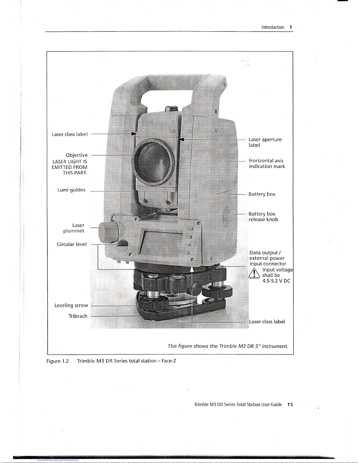
Figure
1.1 and
Figure
1.2
show
the
main
parts
of
the
Trimble
M3
DR
series
instrument.
Figure
1.1
Trimble
M3 DR
Series
total
station
-
Face-l
Stylus
pen
Opticalsight
(Finder)
Telescope
focusing
ring
eyeprece
Diopter
ring
Reticle
plate
cover
Laser
class label
USB
ports
Vertical
tangent
SCTEW
.#--
Battery
box
Face-1
display
/
keyboard
Battery
box
release
knob
Upper
plate
tangent
screw
Label
for FCC
Label
for
CFR
Tribrach
clamp
knob
This
figure showsthe
Trimble
M3
DR
5"
instrument.
14
Trimble
M3
DR
Series
Total Station
User
Guide
Page 3
lntroduction I
Laser class label
Objective
LASER
LIGHT IS
EMITTED
FROM
THIS PART.
Lumi
guides
Laser aperture
label
Horizontal
axis
indication mark
Battery box
Battery box
release knob
Lase
r
plummet
Circular
level
Data
output /
external
power
input connector
f?r.
lnput volt
1lJ
shall be
4.5-5.2
V DC
Leveling screw
Tribrach
Laser
class label
This
figure
shows the Trimble M3 DR
5" instrument.
Figure
1.2 Trimble
M3 DR Series total station
-
Face-2
Trimble M3 DR Series Total
Station User Guide
1 5
Page 4

6 System Diagrams
System components
ry
,*$4,.
[fl:,]F
.-^€E/
/\-v'J
^
v/@
v-ffi
v/n
-a
AC adapter and
plug
adapter
@-
Solar filter
ra)
M
H
tl E
II
s3
Diagonal
eyepiece
@a
Low-powe
eyepiece
c
U58 memory
Trimbre M3 ,ffi
#T:ft'''
ffip
UsBcabre
power
iece
ax
/z:\\
W8;L:',i';|n)'"0'" tfl
t-l
I
r-El
Personal computer
@
High-power
eyepiece
Personal computer
Figure 6.1 Measurement
side
56 Trimble M3 DR Series Total
Station User Guide
Page 5
System Diagrams
6
Coaxial
target
plate
for
single
prism
Taiget pole
R
tl
L]
tl
I
,
*
Mini
prism
C
&
Y
Mini
prism
holder
E
u
w
w
g
&
L-l
Mini
prism
adapter
Standard
round
Ill?I
;ii5:J"
iinii"'p'ism
c
holder
Prism
adapter
/@M i'"':-1i6*1
IM/U I : N/
1
Height
iiustment
adapter
is not
used.
Tribrach
adapter
'l
5
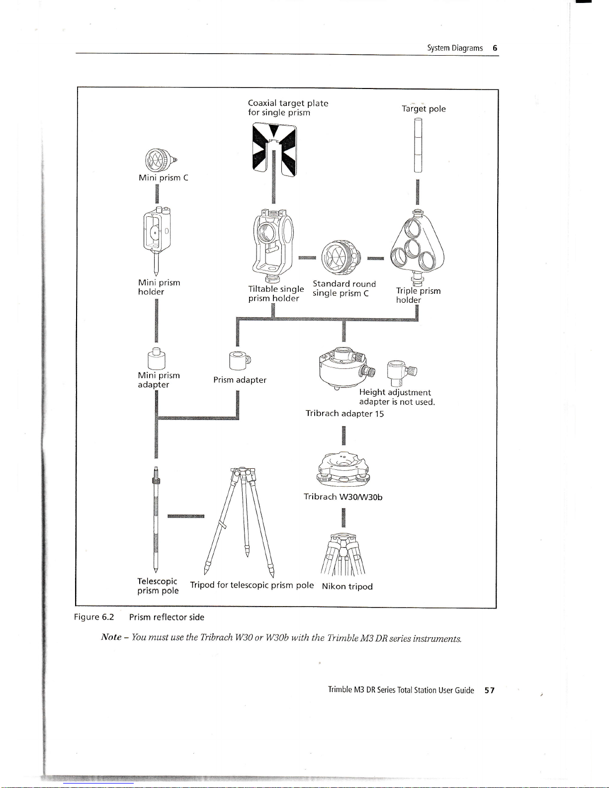
Figure
5.2
Prism reflector
side
Note
*
You
must use the TribrachW30
nr W30b with the Trimble
M3
DR
series instruments.
Trimble
M3 DR
Series Total
Station User Guide 57
Page 6

4
Checking
and
Adjustment
Checking
the
instrument
constant
The
instrument
constant
is
a numerical
value
used
to
automatically
correct
for
the
displacement
between
the
mechanical
and
electrlcal
centers
when
rfle{suring
distances.
The
instrument
constant
is
set by
the
manufacturer
before
the
instrument
is
shipped.
However,
to
ensure
the
highest
operational
accuracy,
we
recommend
that
you
check
the
instrument
constant
several
times
a year.
To check
the
instrument
constant,
you
can either
compare
a
correctly
measured
base line
with
the
distance
measured
by
the
EDM,
or forow
the
procedure
below.
About'100
m
To
check
the
instrument
constant:
1.
set up the
instrument
at
point
B
in
as flat
an
area
as possible.
2'
Set
up a
reflector
prism
at Point
Q
100
m
away
from
Point
P.
Make
sure
that
vou
take
the
prism
constant
into
account.
3.
Measure
the
distance
between
point
p
and
point
a
(pO.
4.
Install
a
reflector prism
on
the
tripod at
point
p.
5.
Set
up another
tripod
at Point
R, on
the line
between
Point
p
and
point
e.
6.
Transfer
the Trimble
M3
DR
series
instrument
to
the
tripod
at
point
R.
7
-
Measure
the
distance
from Point
R
to Point
P
(RP),
and
from
point
R to
point
a
(Ra).
8.
Calculate
the
difference
between
the
value
of
PQ
and
the
value
of Rp +
Re.
9.
Move the
Trimble
M3 DR
series
instrument
to
other points
on
the
line
between
point
p
and
Point
Q.
10.
Repeat
Step
5 through
Step
9 ten
times
or
so.
11.
Calculate
the average
ofall
the
differences.
The
error range
is
within
3 mm.
If
the
error is
out
of
range,
contact
your
dealer.
42
Trimble
M3 DR
Series
Total
Station
User Guide
Page 7

Checking
and Adjustment
4
Checking the
laser
pointer
The
Trimble M3 DR series
total station uses a
red laser
beam to a laser pointer. The laser
pointer is coaxial
with the line of sight of
the telescope.
If the instrument
is well adjusted, the
red
laser pointer coincides
with the line of sight.
External
influences
such as
shock
or large
temperature
fluctuations can displace the
red laser
pointer
relative
to the
line
of sight.
Trlmble
M3 DR Series Total
Station User Guide
 Loading...